EP3065015B1 - Procédé et dispositif de diagnostic destinés à la surveillance du fonctionnement de circuits régulateurs - Google Patents
Procédé et dispositif de diagnostic destinés à la surveillance du fonctionnement de circuits régulateurs Download PDFInfo
- Publication number
- EP3065015B1 EP3065015B1 EP15157643.6A EP15157643A EP3065015B1 EP 3065015 B1 EP3065015 B1 EP 3065015B1 EP 15157643 A EP15157643 A EP 15157643A EP 3065015 B1 EP3065015 B1 EP 3065015B1
- Authority
- EP
- European Patent Office
- Prior art keywords
- control loop
- control
- control loops
- monitored
- diagnostic device
- Prior art date
- Legal status (The legal status is an assumption and is not a legal conclusion. Google has not performed a legal analysis and makes no representation as to the accuracy of the status listed.)
- Active
Links
Images


Classifications
-
- G—PHYSICS
- G05—CONTROLLING; REGULATING
- G05B—CONTROL OR REGULATING SYSTEMS IN GENERAL; FUNCTIONAL ELEMENTS OF SUCH SYSTEMS; MONITORING OR TESTING ARRANGEMENTS FOR SUCH SYSTEMS OR ELEMENTS
- G05B23/00—Testing or monitoring of control systems or parts thereof
- G05B23/02—Electric testing or monitoring
- G05B23/0205—Electric testing or monitoring by means of a monitoring system capable of detecting and responding to faults
- G05B23/0218—Electric testing or monitoring by means of a monitoring system capable of detecting and responding to faults characterised by the fault detection method dealing with either existing or incipient faults
- G05B23/0224—Process history based detection method, e.g. whereby history implies the availability of large amounts of data
- G05B23/024—Quantitative history assessment, e.g. mathematical relationships between available data; Functions therefor; Principal component analysis [PCA]; Partial least square [PLS]; Statistical classifiers, e.g. Bayesian networks, linear regression or correlation analysis; Neural networks
-
- G—PHYSICS
- G05—CONTROLLING; REGULATING
- G05B—CONTROL OR REGULATING SYSTEMS IN GENERAL; FUNCTIONAL ELEMENTS OF SUCH SYSTEMS; MONITORING OR TESTING ARRANGEMENTS FOR SUCH SYSTEMS OR ELEMENTS
- G05B23/00—Testing or monitoring of control systems or parts thereof
- G05B23/02—Electric testing or monitoring
- G05B23/0205—Electric testing or monitoring by means of a monitoring system capable of detecting and responding to faults
- G05B23/0218—Electric testing or monitoring by means of a monitoring system capable of detecting and responding to faults characterised by the fault detection method dealing with either existing or incipient faults
- G05B23/0221—Preprocessing measurements, e.g. data collection rate adjustment; Standardization of measurements; Time series or signal analysis, e.g. frequency analysis or wavelets; Trustworthiness of measurements; Indexes therefor; Measurements using easily measured parameters to estimate parameters difficult to measure; Virtual sensor creation; De-noising; Sensor fusion; Unconventional preprocessing inherently present in specific fault detection methods like PCA-based methods
Definitions
- the invention relates to a diagnostic device for monitoring the operation of control circuits of an automation system according to the preamble of claim 1 and to a corresponding diagnostic method according to the preamble of claim 10.
- a diagnostic method for monitoring the operation of a control loop is already out of the EP 1 528 447 B1 known.
- the variance of a sequence of actual value data is determined as a stochastic feature and evaluated for an analysis of the state of the control loop.
- the relative overshoot or the transient response ie the quotient of the rise and settling time of the controlled variable, are evaluated as deterministic features for the analysis of the control loop state.
- the invention is therefore based on the object to provide a diagnostic device and a diagnostic method for monitoring the operation of control loops, which indicate interactions of one control loop to another and thus allow a direct assessment of the interactions of the individual control circuits with each other.
- the new diagnostic device of the type mentioned in the characterizing part of claim 1 features.
- a diagnostic method described in claim 11 a computer program for performing the diagnostic method and in claim 12, a corresponding computer program product.
- the invention has the advantage that it allows the monitoring of control circuits on interactions of the control circuits with each other and their evaluation by particularly vivid presentation of the monitoring result. As a result, a significant improvement in the system behavior can be achieved.
- the invention also has the advantage that no scaling factors are required for the application of the diagnostic method or for the use of the diagnostic device and, moreover, that no background knowledge about a process running on the system or about the automated system is required. The diagnosis is thus carried out in a particularly simple manner by a user.
- ⁇ represent a positive time offset of the signal x relative to the duration of one sampling interval Signal y
- ⁇ x 2 the variance of the signal x
- ⁇ y 2 the variance of the signal y
- the cross-correlation function of the controlled variables with positive time offset ⁇ of the controlled variable of the other control loop is advantageously used. If an excitation of the one control loop by a change in a desired value specification, for example with a ramp-shaped course or preferably with a curve corresponding to a step function, affects the control variable of the other control loop, a large value can be found in the cross-correlation function. The stronger the coupling, the larger the function values of the cross-correlation function become. If, on the other hand, there is no influence, the cross-correlation function will only assume relatively small values.
- additional sequences of control value data to be monitored control loops can be stored in the data memory and analogously to the determination of the first measure, d. H.
- a second measure is determined based on control value data and the arithmetic mean of the two measures calculated. If the controller of one control loop is set comparatively quickly, it will immediately correct the transverse influence of another control loop, which can lead to the result that no interaction can be detected in the course of the controlled variable. Due to the active intervention of the fast regulator, i. H. a controller with a fast response to a possible control difference, however, the transverse influence in the manipulated variable generated by it is clearly visible.
- the mean value of the magnitude of the two cross-correlation functions of control variables and manipulated variables can advantageously be determined and displayed.
- a limit value can be defined to determine from when it is a real coupling, which as interference may cause interference, and until when it is probably just noise or other interference.
- this value can be set to 0.6, for example, because in cases of strong coupling between two control loops, the cross-correlation functions will take much larger values. Of course, due to the definition of the cross-correlation function, this value can not exceed 1.
- the direction of the coupling with its direction of action can also be determined and displayed on the basis of the cross-correlation function become. In this way, a statement is advantageously possible as to whether a positive nominal value change at the one control circuit triggers a positive or a negative change in the controlled variable at the respective other control loop of the pair of control circuits to be monitored.
- the sums of the key figures are calculated on the basis of the matrix.
- a sorted list of all control loops is available in a simple manner according to the respective influence which they exert on the other control loops.
- Control circuits which have a particularly great significance in this sense, can be treated with special priority within the framework of an optimization of the automation system subsequent to the diagnosis in order to remedy any difficulties that have been identified.
- the diagnostic device can in the same way as the already from the EP 1 528 447 B1 Known diagnostic device can be advantageously designed as a software function block that can be interconnected in a graphical user interface of an engineering system with function blocks of the control loop and for operating the diagnostic device in a Automation device is loadable.
- the calculated key figures or the key figure matrix are then displayed on a so-called faceplate for realizing a human-machine interface on an operating and monitoring device of the automation system.
- an operator may, if desired, make a change in the parameterization, for example an adjustment of the limit value for the display of a warning message with an increased value of the metric, etc.
- the new diagnostic device for monitoring the operation of a control loop can be implemented in a software environment for cloud-based control loop monitoring.
- a software environment for example, is the data-based remote service "Control Performance Analytics” from Siemens AG. Data from customer systems are collected using software agents, aggregated and sent to a Siemens Service Operation Center, where they are stored on a remote service Calculator can be saved. There, they are semi-automatically evaluated using various "Data Analytics" software applications. If required, specially trained experts can work very efficiently on this database for remote service. The results of the data analysis can be displayed on a monitor of the remote service computer and / or provided on a sharepoint so that it can be used by the end user, i. H. the operator of the automation system, z. B. in a browser can be considered.
- the diagnostic method is thus preferably implemented in software or in a combination of software / hardware, so that the invention also relates to a computer program with computer-executable program code instructions for implementing the diagnostic method.
- the invention also relates to a computer program product, in particular a data carrier or a storage medium, with a computer program executable by a computer.
- One such computer program can, as described above, be kept in or loaded into a memory of an automation device, so that the operation of the automation device, the monitoring of the operation of control loops is automatically performed, or the computer program can in a cloud-based monitoring of control loops in a memory a remote service computer held or loadable in this.
- FIG. 1 shows an example with three to be monitored control loops RK1, RK2 and RK3, which are used in an automation system, not shown.
- the control circuits RK1 and RK2 are used in a real system for controlling a respective flow as a controlled variable PV1 or PV2, the control loop RK3 for controlling a level in a tank as a controlled variable PV3.
- actuators P1, P2 and P3 respectively control valves are used.
- the control circuit RK1 controls a main flow to the tank, the level of which is regulated by the control circuit RK3.
- the control circuit RK2 is located in a side flow path parallel to the main flow with a lower flow rate and thus regulates the flow in a second path, on which a medium, such as water, can flow into the tank.
- the RK3 control circuit uses a drain valve, through which medium is drained from the tank.
- RK1, RK2 and RK3 setpoints are still with the reference numerals SP1, SP2 and SP3, controller with the reference numerals R1, R2 and R3 and manipulated variables with the reference numerals MV1, MV2 and MV3 respectively.
- the setpoint values SP1, SP2 and SP3, the manipulated variables MV1, MV2 and MV3 and the controlled variables PV1, PV2 and PV3 are passed to a diagnostic device D and stored there as sequences of setpoint data, manipulated variable data or actual value data in a data memory DS.
- an evaluation device AE calculates parameters KKF, a matrix M and / or a list L (FIG. FIG. 1 ), which are displayed to an operator to evaluate an interaction of the control circuits RK1, RK2 and RK3.
- This provides an accurate indication of the strength and direction of the interactions, thus making it easier for the user to understand possible causes of trouble due to cross-influences of the control system's control circuits RK1, RK2 and RK3.
- a limit value of 0.6 is exceeded by a parameter KKF, for example, a warning signal W is output.
- undesirable strong lateral dynamics between subsystems which have been discovered in this way, can be specifically reduced by improving the control structure, for example by using a multivariable controller. Reducing the impact of the overall process can potentially increase productivity and reduce costs.
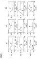
- FIG. 2 shows different curves of the setpoints SP1, SP2 and SP3 as well as the controlled variables PV1, PV2 and PV3,
- FIG. 2 shows curves of the manipulated variables MV1, MV2 and MV3 in diagrams.
- the row inscription indicates in which control loop RK1, RK2 or RK3 a desired value jump was carried out as an excitation of the respective control loop RK1, RK2 or RK3.
- the column inscription indicates from which control loop RK1, RK2 or RK3 the data shown in the respective diagram originate.
- At the abscissa are the respective numbers of the scans, engl. samples, d h. the number of a record in the respective sequence of data, plotted.
- the respective flow rate L / h (liters / hour) is plotted, on the ordinates of the diagrams, which are assigned to the control loop RK3, the filling level of the tank as an indication in% (percent).
- the curves 11, 12 and 13 are setpoint curves, which were recorded on the control loop RK1, the curves 14, 15 and 16 setpoint curves of the control loop RK2 and the curves 17, 18 and 19 setpoint curves of the control loop RK3. It should be noted that the curve 14 lies on the abscissa of the relevant diagram, since the setpoint PV2 is constant 150 L / h.
- the curves 21, 22 and 23 are actual value curves of the control loop RK1, the curves 24, 25 and 26 actual value curves of the control loop RK2 and the curves 27, 28 and 29 actual value curves of the control loop RK3.
- Curves 31, 32 and 33 shown are control value curves of the control loop RK1, the curves 34, 35 and 36 control variables of the control loop RK2 and the curves 37, 38 and 39 control variables of the control loop RK3.
- the cross-correlation function for all possible, positive time shifts ⁇ of the course 24 is calculated with respect to the course 21 and the magnitude maximum of this cross-correlation function is determined as a first measure.
- a second measure is calculated.
- a characteristic KKF 1, 2 is obtained, which enables an evaluation of the interaction of the control loop RK 1 with the control loop RK 2.
- a parameter for evaluating the interaction is calculated in a corresponding manner for each possible pair of control loops RK1, RK2 and RK3 and for each direction of influence within the respective pair.
- a matrix can now be created for an automation system with n control loops to be monitored as a result of the calculations, whose field elements on the main diagonal always have the value 1 of the autocorrelation function AKF and otherwise the values of the various cross-correlation functions KKF i, j with i-row index and j - column index.
- the polarities of the calculated for the determination of the first measures cross-correlation functions are determined in each case at its absolute maximum and negative polarity by a positive sign in the respective characteristic in the same direction effective direction of a control loop to the other control loop and positive polarity a negative sign in the respective characteristic an opposite direction of action of the one control loop displayed on the other loop.
- the user can thus simultaneously display the strengths of the interactions of control loops and the respective direction of action.
- the mean value of the amounts of the cross-correlation functions of the control and manipulated variables is provided for this purpose with the sign set in the above manner and is obtained for the basis of the FIGS. 1 to 3 described example with three control loops RK1, RK2 and RK3 the following table as a result of the interaction analysis, in which the individual characteristics KKF are shown in matrix representation: ⁇ on influence of RK1 RK2 RK3 RK1 100% -54.2% 68.6% RK2 -73.8% 100% 26.2% RK3 0% 0% -100%
- control loop RK1 or control loop RK2 An increasing flow in the control loop RK1 or control loop RK2 is associated with an interaction with the other flow control loop RK2 or RK1 with negative direction of action, while the level of the control loop RK3 will increase according to a positive sense of action. Since the control circuit RK3 regulates the level of the tank via its outflow, it has a negative gain in the transfer function of the route P3.
- the method allows reliable diagnostic statements about the strength and the efficiency of the couplings between control loops, which are clearly displayed in a matrix of percentages and signs.
- undesirably strong transverse dynamics between control loops which have been discovered in this way can be purposefully reduced by improving the control structure, for example by using a multivariable controller.
- productivity can be increased and costs reduced.
- the diagnostic procedure also provides a sorted list of all control loops according to their influence on the other control loops. Control loops, which are particularly important in this sense, can be treated with special priority in the context of monitoring and optimizing the control quality.
Landscapes
- Physics & Mathematics (AREA)
- Engineering & Computer Science (AREA)
- General Physics & Mathematics (AREA)
- Automation & Control Theory (AREA)
- Artificial Intelligence (AREA)
- Evolutionary Computation (AREA)
- Mathematical Physics (AREA)
- Testing And Monitoring For Control Systems (AREA)
- Feedback Control In General (AREA)
Claims (12)
- Dispositif de diagnostic pour contrôler le fonctionnement de circuits (RK1, RK2, RK3) de régulation d'un système d'automatisation, dans lequel le dispositif (D) de diagnostic est constitué pour mémoriser, dans une mémoire (DS) de données, des séquences de données de valeur réelle du circuit (RK1, RK2, RK3) de régulation à contrôler, caractérisé par un dispositif (AE) d'exploitation, constitué pour déterminer, lors d'une excitation donnée à l'avance ou pouvant l'être, par une modification d'une prescription de valeur de consigne de l'un des circuits (RK1) de régulation d'une paire de circuits (RK1, RK2) de régulation à contrôler, à l'aide d'au moins respectivement une partie des séquences de données de valeur réelle de la paire de circuits de régulation à contrôler, comme première cote, le maximum en valeur absolue de la fonction de corrélation croisée pour un décalage temporel positif de la séquence de données de valeur réelle de respectivement l'autre circuit (RK2) de régulation de la paire de circuits de régulation à contrôler et, en fonction de la première cote, déterminer et afficher une grandeur (KKF) caractéristique pour l'évaluation d'une interaction du un circuit (RK1) de régulation avec l'autre circuit (RK2) de régulation.
- Dispositif de diagnostic suivant la revendication 1, caractérisé en ce que l'excitation donnée à l'avance ou pouvant l'être est un saut de valeur de consigne de niveau donné à l'avance ou pouvant l'être.
- Dispositif de diagnostic suivant la revendication 1 ou 2, caractérisé en ce que des séquences de données de valeur de réglage des circuits (RK1, RK2, RK3) de régulation à contrôler peuvent être mémorisées dans la mémoire (DS) de données, en ce que, d'une manière analogue à la détermination de la première cote, une deuxième cote peut être déterminée à l'aide de données de valeur de réglage et en ce que le nombre (KKF) caractéristique est la moyenne arithmétique de la première cote et de la deuxième cote.
- Dispositif de diagnostic suivant l'une des revendications précédentes, caractérisé en ce qu'un signal (W) d'alerte peut être émis si le nombre (KKF) caractéristique dépasse une valeur limite donnée à l'avance ou pouvant l'être.
- Dispositif de diagnostic suivant l'une des revendications précédentes, caractérisé en ce que la polarité de la fonction de corrélation croisée calculée pour la détermination de la première cote est déterminé à son maximum en valeur absolue et en ce que, pour une polarité négative, on affiche une direction d'effet de même sens du un circuit (RK1) de régulation sur l'autre circuit (RK2) de régulation et, pour une polarité positive, une direction d'effet de sens contraire du un circuit (RK1) de régulation sur l'autre circuit (RK2) de régulation.
- Dispositif de diagnostic suivant l'une des revendications précédentes, caractérisé en ce qu'une matrice (M) peut être affichée, dans laquelle des nombres (KKFi,j, i ≠ j) caractéristiques sont portés pour évaluer l'interaction du ième circuit de régulation des circuits de régulation à contrôle sur le jème circuit de régulation des circuits de régulation à contrôler.
- Dispositif de diagnostic suivant la revendication 6, caractérisé en ce que, dans la matrice (M) peut être affiché une direction d'effet de même sens ou de sens contraire.
- Dispositif de diagnostic suivant la revendication 6 ou 7, caractérisé en ce qu'à l'aide de la matrice (M), peuvent être déterminées et affichées des sommes de ligne des valeurs absolues des nombres caractéristiques.
- Dispositif de diagnostic suivant l'une des revendications précédentes, caractérisé en ce qu'au moins la mémoire (DS) de données et le dispositif (AE) d'exploitation sont mis en oeuvre par logiciel sur un ordinateur remote service pour le télédiagnostic du circuit de régulation.
- Procédé de diagnostic pour le contrôle du fonctionnement de circuits (RK1, RK2, RK3) de régulation d'un système d'automatisation, caractérisé par les stades suivants :- mémorisation respectivement d'une séquence de données de valeur réelle de deux circuits (RK1, RK2) de régulation d'une paire de circuits (RK1, RK2, RK3) de régulation à contrôler,- lors d'une excitation donnée à l'avance ou pouvant l'être par une modification d'une prescription de valeur de consigne du un circuit (RK1) de régulation de la paire de circuits de régulation à contrôler, à l'aide d'au moins respectivement une partie des séquences de données de valeur réelle, détermination du maximum en valeur absolue de la fonction de corrélation croisée pour un décalage temporel positif des séquences de données de valeur réelle de respectivement l'autre circuit (RK2) de régulation de la paire de circuits de régulation à contrôler, comme première cote et- en fonction de la première cote, détermination et affichage d'une grandeur (KKF) caractéristique pour l'évaluation d'une interaction du un circuit (RK1) de régulation avec l'autre circuit (RK2) de régulation.
- Programme d'ordinateur ayant des instructions de côte de programme pouvant être réalisées sur un ordinateur pour la mise en oeuvre du procédé suivant la revendication 12, lorsque le programme d'ordinateur est réalisé sur un ordinateur.
- Produit de programme d'ordinateur, notamment support de données ou support de mémoire, ayant un programme d'ordinateur suivant la revendication 11, pouvant être réalisé par un ordinateur.
Priority Applications (3)
| Application Number | Priority Date | Filing Date | Title |
|---|---|---|---|
| EP15157643.6A EP3065015B1 (fr) | 2015-03-04 | 2015-03-04 | Procédé et dispositif de diagnostic destinés à la surveillance du fonctionnement de circuits régulateurs |
| US15/041,339 US10175685B2 (en) | 2015-03-04 | 2016-02-11 | Diagnostic device and method for monitoring the operation of control loops |
| CN201610109346.4A CN105938361B (zh) | 2015-03-04 | 2016-02-26 | 用于监控调节回路的运行的诊断装置和诊断方法 |
Applications Claiming Priority (1)
| Application Number | Priority Date | Filing Date | Title |
|---|---|---|---|
| EP15157643.6A EP3065015B1 (fr) | 2015-03-04 | 2015-03-04 | Procédé et dispositif de diagnostic destinés à la surveillance du fonctionnement de circuits régulateurs |
Publications (2)
| Publication Number | Publication Date |
|---|---|
| EP3065015A1 EP3065015A1 (fr) | 2016-09-07 |
| EP3065015B1 true EP3065015B1 (fr) | 2018-09-26 |
Family
ID=52697207
Family Applications (1)
| Application Number | Title | Priority Date | Filing Date |
|---|---|---|---|
| EP15157643.6A Active EP3065015B1 (fr) | 2015-03-04 | 2015-03-04 | Procédé et dispositif de diagnostic destinés à la surveillance du fonctionnement de circuits régulateurs |
Country Status (3)
| Country | Link |
|---|---|
| US (1) | US10175685B2 (fr) |
| EP (1) | EP3065015B1 (fr) |
| CN (1) | CN105938361B (fr) |
Families Citing this family (3)
| Publication number | Priority date | Publication date | Assignee | Title |
|---|---|---|---|---|
| US10678224B2 (en) * | 2017-06-21 | 2020-06-09 | Fisher-Rosemount Systems, Inc. | Loop interface |
| EP3489774B1 (fr) | 2017-11-22 | 2024-04-17 | Siemens Aktiengesellschaft | Détermination automatisée du paramétrage d'un procédé d'évaluation |
| EP3591482A1 (fr) * | 2018-07-03 | 2020-01-08 | Siemens Aktiengesellschaft | Surveillance d'une installation technique |
Family Cites Families (8)
| Publication number | Priority date | Publication date | Assignee | Title |
|---|---|---|---|---|
| GB9608953D0 (en) * | 1996-04-29 | 1996-07-03 | Pulp Paper Res Inst | Automatic control loop monitoring and diagnostics |
| JP2000214903A (ja) | 1999-01-25 | 2000-08-04 | Yutaka Maeda | 摂動を用いた制御器のパラメ―タ調整方式 |
| US6650947B2 (en) | 2001-03-23 | 2003-11-18 | Metso Automation Oy | Multi-variable control loop assessment |
| DE10350610A1 (de) | 2003-10-30 | 2005-06-09 | Siemens Ag | Diagnoseeinrichtung und -verfahren zur Überwachung des Betriebs eines Regelkreises |
| US8509926B2 (en) | 2005-12-05 | 2013-08-13 | Fisher-Rosemount Systems, Inc. | Self-diagnostic process control loop for a process plant |
| US7953501B2 (en) | 2006-09-25 | 2011-05-31 | Fisher-Rosemount Systems, Inc. | Industrial process control loop monitor |
| CN101403924A (zh) | 2008-11-03 | 2009-04-08 | 东华大学 | 一种控制回路在线迟滞检测的方法 |
| CN104950873B (zh) | 2015-05-29 | 2017-07-21 | 浙江大学 | 工业控制回路间歇振荡的在线检测方法 |
-
2015
- 2015-03-04 EP EP15157643.6A patent/EP3065015B1/fr active Active
-
2016
- 2016-02-11 US US15/041,339 patent/US10175685B2/en active Active
- 2016-02-26 CN CN201610109346.4A patent/CN105938361B/zh active Active
Non-Patent Citations (1)
| Title |
|---|
| None * |
Also Published As
| Publication number | Publication date |
|---|---|
| CN105938361A (zh) | 2016-09-14 |
| US20160259328A1 (en) | 2016-09-08 |
| EP3065015A1 (fr) | 2016-09-07 |
| US10175685B2 (en) | 2019-01-08 |
| CN105938361B (zh) | 2018-09-21 |
Similar Documents
| Publication | Publication Date | Title |
|---|---|---|
| DE112019001512T5 (de) | EINSPRITZGIEßMASCHINENSYSTEM | |
| DE102004042813A1 (de) | Alarmmanagementsystem | |
| EP1250632A1 (fr) | Systeme et procede pour determiner l'efficacite d'unites de production, des evenements d'erreurs et la cause desdites erreurs | |
| EP3268713B1 (fr) | Procédé de réalisation d'un ensemble de modèles permettant d'étalonner un appareil de commande | |
| EP3282399B1 (fr) | Procede de reconnaissance ameliore d'anomalies de processus d'une installation technique et systeme de diagnostic correspondant | |
| EP3232282B1 (fr) | Dispositif de diagnostic et procede de surveillance du fonctionnement d'une installation technique | |
| DE102009021774A1 (de) | Verfahren und Einrichtung zur Identifikation von Korrelationen zwischen Alarmmeldungen oder zwischen Alarmmeldungen und Bedieneingriffen | |
| DE10310116A1 (de) | Risikominimierung und Wartungsoptimierung durch Ermittlung von Schädigungsanteilen aus Betriebsdaten | |
| EP3065015B1 (fr) | Procédé et dispositif de diagnostic destinés à la surveillance du fonctionnement de circuits régulateurs | |
| DE4338607B4 (de) | Verfahren und Vorrichtung zur Führung eines Prozesses in einem geregelten System | |
| DE102014223810A1 (de) | Verfahren und Assistenzsystem zur Erkennung einer Störung in einer Anlage | |
| WO2000042480A1 (fr) | Controle de la qualite dans une fabrication | |
| WO2020064712A1 (fr) | Procédé pour l'amélioration de la priorisation de messages, composant logiciel, système de commande et d'observation et système d'automatisation | |
| EP3056957B1 (fr) | Procédé et dispositif de diagnostic destinés à la surveillance du fonctionnement d'un circuit régulateur | |
| DE102008029641A1 (de) | Steueranordnung mit einem Druckbegrenzungsventil | |
| DE1523535C3 (de) | Selbstanpassender Regelkreis | |
| EP1528447B1 (fr) | Procédé et dispositf de diagnostic pour la surveillance du fonctionnement d'une boucle de réglage | |
| EP3542229B1 (fr) | Dispositif et procédé de détermination des paramètres d'un dispositif de réglage | |
| DE3721504A1 (de) | Regelsystem | |
| EP3121672B1 (fr) | Procede et dispositif de diagnostic destines a la surveillance du fonctionnement d'un circuit regulateur | |
| EP1556811A2 (fr) | Prevision du degre de respect des delais de livraison dans la fabrication en serie | |
| WO2010094487A1 (fr) | Procédé et dispositif de surveillance d'une installation de pasteurisation | |
| DE102019203775A1 (de) | Verfahren und Vorrichtung zur Verwendung der Fehlerfortpflanzung | |
| DE102017216749A1 (de) | Verfahren zur Bereitstellung eines Steuersignals | |
| Lindemann | Datengetriebene Kompensation anomaler Prozessdynamiken in Automatisierungssystemen auf Basis adaptiver LSTM-Netze |
Legal Events
| Date | Code | Title | Description |
|---|---|---|---|
| PUAI | Public reference made under article 153(3) epc to a published international application that has entered the european phase |
Free format text: ORIGINAL CODE: 0009012 |
|
| AK | Designated contracting states |
Kind code of ref document: A1 Designated state(s): AL AT BE BG CH CY CZ DE DK EE ES FI FR GB GR HR HU IE IS IT LI LT LU LV MC MK MT NL NO PL PT RO RS SE SI SK SM TR |
|
| AX | Request for extension of the european patent |
Extension state: BA ME |
|
| STAA | Information on the status of an ep patent application or granted ep patent |
Free format text: STATUS: REQUEST FOR EXAMINATION WAS MADE |
|
| 17P | Request for examination filed |
Effective date: 20170220 |
|
| RBV | Designated contracting states (corrected) |
Designated state(s): AL AT BE BG CH CY CZ DE DK EE ES FI FR GB GR HR HU IE IS IT LI LT LU LV MC MK MT NL NO PL PT RO RS SE SI SK SM TR |
|
| RAP1 | Party data changed (applicant data changed or rights of an application transferred) |
Owner name: SIEMENS AKTIENGESELLSCHAFT |
|
| GRAP | Despatch of communication of intention to grant a patent |
Free format text: ORIGINAL CODE: EPIDOSNIGR1 |
|
| STAA | Information on the status of an ep patent application or granted ep patent |
Free format text: STATUS: GRANT OF PATENT IS INTENDED |
|
| RIC1 | Information provided on ipc code assigned before grant |
Ipc: G05B 23/02 20060101AFI20180607BHEP |
|
| INTG | Intention to grant announced |
Effective date: 20180628 |
|
| GRAS | Grant fee paid |
Free format text: ORIGINAL CODE: EPIDOSNIGR3 |
|
| GRAA | (expected) grant |
Free format text: ORIGINAL CODE: 0009210 |
|
| STAA | Information on the status of an ep patent application or granted ep patent |
Free format text: STATUS: THE PATENT HAS BEEN GRANTED |
|
| AK | Designated contracting states |
Kind code of ref document: B1 Designated state(s): AL AT BE BG CH CY CZ DE DK EE ES FI FR GB GR HR HU IE IS IT LI LT LU LV MC MK MT NL NO PL PT RO RS SE SI SK SM TR |
|
| REG | Reference to a national code |
Ref country code: GB Ref legal event code: FG4D Free format text: NOT ENGLISH |
|
| REG | Reference to a national code |
Ref country code: CH Ref legal event code: EP |
|
| REG | Reference to a national code |
Ref country code: AT Ref legal event code: REF Ref document number: 1046767 Country of ref document: AT Kind code of ref document: T Effective date: 20181015 |
|
| REG | Reference to a national code |
Ref country code: IE Ref legal event code: FG4D Free format text: LANGUAGE OF EP DOCUMENT: GERMAN |
|
| REG | Reference to a national code |
Ref country code: DE Ref legal event code: R096 Ref document number: 502015006041 Country of ref document: DE |
|
| REG | Reference to a national code |
Ref country code: NL Ref legal event code: MP Effective date: 20180926 |
|
| PG25 | Lapsed in a contracting state [announced via postgrant information from national office to epo] |
Ref country code: GR Free format text: LAPSE BECAUSE OF FAILURE TO SUBMIT A TRANSLATION OF THE DESCRIPTION OR TO PAY THE FEE WITHIN THE PRESCRIBED TIME-LIMIT Effective date: 20181227 Ref country code: RS Free format text: LAPSE BECAUSE OF FAILURE TO SUBMIT A TRANSLATION OF THE DESCRIPTION OR TO PAY THE FEE WITHIN THE PRESCRIBED TIME-LIMIT Effective date: 20180926 Ref country code: FI Free format text: LAPSE BECAUSE OF FAILURE TO SUBMIT A TRANSLATION OF THE DESCRIPTION OR TO PAY THE FEE WITHIN THE PRESCRIBED TIME-LIMIT Effective date: 20180926 Ref country code: BG Free format text: LAPSE BECAUSE OF FAILURE TO SUBMIT A TRANSLATION OF THE DESCRIPTION OR TO PAY THE FEE WITHIN THE PRESCRIBED TIME-LIMIT Effective date: 20181226 Ref country code: NO Free format text: LAPSE BECAUSE OF FAILURE TO SUBMIT A TRANSLATION OF THE DESCRIPTION OR TO PAY THE FEE WITHIN THE PRESCRIBED TIME-LIMIT Effective date: 20181226 Ref country code: SE Free format text: LAPSE BECAUSE OF FAILURE TO SUBMIT A TRANSLATION OF THE DESCRIPTION OR TO PAY THE FEE WITHIN THE PRESCRIBED TIME-LIMIT Effective date: 20180926 Ref country code: LT Free format text: LAPSE BECAUSE OF FAILURE TO SUBMIT A TRANSLATION OF THE DESCRIPTION OR TO PAY THE FEE WITHIN THE PRESCRIBED TIME-LIMIT Effective date: 20180926 |
|
| REG | Reference to a national code |
Ref country code: LT Ref legal event code: MG4D |
|
| PG25 | Lapsed in a contracting state [announced via postgrant information from national office to epo] |
Ref country code: AL Free format text: LAPSE BECAUSE OF FAILURE TO SUBMIT A TRANSLATION OF THE DESCRIPTION OR TO PAY THE FEE WITHIN THE PRESCRIBED TIME-LIMIT Effective date: 20180926 Ref country code: HR Free format text: LAPSE BECAUSE OF FAILURE TO SUBMIT A TRANSLATION OF THE DESCRIPTION OR TO PAY THE FEE WITHIN THE PRESCRIBED TIME-LIMIT Effective date: 20180926 Ref country code: LV Free format text: LAPSE BECAUSE OF FAILURE TO SUBMIT A TRANSLATION OF THE DESCRIPTION OR TO PAY THE FEE WITHIN THE PRESCRIBED TIME-LIMIT Effective date: 20180926 |
|
| PG25 | Lapsed in a contracting state [announced via postgrant information from national office to epo] |
Ref country code: ES Free format text: LAPSE BECAUSE OF FAILURE TO SUBMIT A TRANSLATION OF THE DESCRIPTION OR TO PAY THE FEE WITHIN THE PRESCRIBED TIME-LIMIT Effective date: 20180926 Ref country code: IS Free format text: LAPSE BECAUSE OF FAILURE TO SUBMIT A TRANSLATION OF THE DESCRIPTION OR TO PAY THE FEE WITHIN THE PRESCRIBED TIME-LIMIT Effective date: 20190126 Ref country code: PL Free format text: LAPSE BECAUSE OF FAILURE TO SUBMIT A TRANSLATION OF THE DESCRIPTION OR TO PAY THE FEE WITHIN THE PRESCRIBED TIME-LIMIT Effective date: 20180926 Ref country code: CZ Free format text: LAPSE BECAUSE OF FAILURE TO SUBMIT A TRANSLATION OF THE DESCRIPTION OR TO PAY THE FEE WITHIN THE PRESCRIBED TIME-LIMIT Effective date: 20180926 Ref country code: NL Free format text: LAPSE BECAUSE OF FAILURE TO SUBMIT A TRANSLATION OF THE DESCRIPTION OR TO PAY THE FEE WITHIN THE PRESCRIBED TIME-LIMIT Effective date: 20180926 Ref country code: RO Free format text: LAPSE BECAUSE OF FAILURE TO SUBMIT A TRANSLATION OF THE DESCRIPTION OR TO PAY THE FEE WITHIN THE PRESCRIBED TIME-LIMIT Effective date: 20180926 Ref country code: EE Free format text: LAPSE BECAUSE OF FAILURE TO SUBMIT A TRANSLATION OF THE DESCRIPTION OR TO PAY THE FEE WITHIN THE PRESCRIBED TIME-LIMIT Effective date: 20180926 Ref country code: IT Free format text: LAPSE BECAUSE OF FAILURE TO SUBMIT A TRANSLATION OF THE DESCRIPTION OR TO PAY THE FEE WITHIN THE PRESCRIBED TIME-LIMIT Effective date: 20180926 |
|
| PG25 | Lapsed in a contracting state [announced via postgrant information from national office to epo] |
Ref country code: SM Free format text: LAPSE BECAUSE OF FAILURE TO SUBMIT A TRANSLATION OF THE DESCRIPTION OR TO PAY THE FEE WITHIN THE PRESCRIBED TIME-LIMIT Effective date: 20180926 Ref country code: PT Free format text: LAPSE BECAUSE OF FAILURE TO SUBMIT A TRANSLATION OF THE DESCRIPTION OR TO PAY THE FEE WITHIN THE PRESCRIBED TIME-LIMIT Effective date: 20190126 Ref country code: SK Free format text: LAPSE BECAUSE OF FAILURE TO SUBMIT A TRANSLATION OF THE DESCRIPTION OR TO PAY THE FEE WITHIN THE PRESCRIBED TIME-LIMIT Effective date: 20180926 |
|
| REG | Reference to a national code |
Ref country code: DE Ref legal event code: R097 Ref document number: 502015006041 Country of ref document: DE |
|
| PG25 | Lapsed in a contracting state [announced via postgrant information from national office to epo] |
Ref country code: DK Free format text: LAPSE BECAUSE OF FAILURE TO SUBMIT A TRANSLATION OF THE DESCRIPTION OR TO PAY THE FEE WITHIN THE PRESCRIBED TIME-LIMIT Effective date: 20180926 |
|
| PLBE | No opposition filed within time limit |
Free format text: ORIGINAL CODE: 0009261 |
|
| STAA | Information on the status of an ep patent application or granted ep patent |
Free format text: STATUS: NO OPPOSITION FILED WITHIN TIME LIMIT |
|
| 26N | No opposition filed |
Effective date: 20190627 |
|
| PG25 | Lapsed in a contracting state [announced via postgrant information from national office to epo] |
Ref country code: SI Free format text: LAPSE BECAUSE OF FAILURE TO SUBMIT A TRANSLATION OF THE DESCRIPTION OR TO PAY THE FEE WITHIN THE PRESCRIBED TIME-LIMIT Effective date: 20180926 Ref country code: MC Free format text: LAPSE BECAUSE OF FAILURE TO SUBMIT A TRANSLATION OF THE DESCRIPTION OR TO PAY THE FEE WITHIN THE PRESCRIBED TIME-LIMIT Effective date: 20180926 |
|
| REG | Reference to a national code |
Ref country code: CH Ref legal event code: PL |
|
| GBPC | Gb: european patent ceased through non-payment of renewal fee |
Effective date: 20190304 |
|
| PG25 | Lapsed in a contracting state [announced via postgrant information from national office to epo] |
Ref country code: LU Free format text: LAPSE BECAUSE OF NON-PAYMENT OF DUE FEES Effective date: 20190304 |
|
| REG | Reference to a national code |
Ref country code: BE Ref legal event code: MM Effective date: 20190331 |
|
| PG25 | Lapsed in a contracting state [announced via postgrant information from national office to epo] |
Ref country code: CH Free format text: LAPSE BECAUSE OF NON-PAYMENT OF DUE FEES Effective date: 20190331 Ref country code: GB Free format text: LAPSE BECAUSE OF NON-PAYMENT OF DUE FEES Effective date: 20190304 Ref country code: LI Free format text: LAPSE BECAUSE OF NON-PAYMENT OF DUE FEES Effective date: 20190331 Ref country code: IE Free format text: LAPSE BECAUSE OF NON-PAYMENT OF DUE FEES Effective date: 20190304 |
|
| PG25 | Lapsed in a contracting state [announced via postgrant information from national office to epo] |
Ref country code: FR Free format text: LAPSE BECAUSE OF NON-PAYMENT OF DUE FEES Effective date: 20190331 Ref country code: BE Free format text: LAPSE BECAUSE OF NON-PAYMENT OF DUE FEES Effective date: 20190331 |
|
| PG25 | Lapsed in a contracting state [announced via postgrant information from national office to epo] |
Ref country code: TR Free format text: LAPSE BECAUSE OF FAILURE TO SUBMIT A TRANSLATION OF THE DESCRIPTION OR TO PAY THE FEE WITHIN THE PRESCRIBED TIME-LIMIT Effective date: 20180926 |
|
| PG25 | Lapsed in a contracting state [announced via postgrant information from national office to epo] |
Ref country code: MT Free format text: LAPSE BECAUSE OF FAILURE TO SUBMIT A TRANSLATION OF THE DESCRIPTION OR TO PAY THE FEE WITHIN THE PRESCRIBED TIME-LIMIT Effective date: 20180926 |
|
| REG | Reference to a national code |
Ref country code: AT Ref legal event code: MM01 Ref document number: 1046767 Country of ref document: AT Kind code of ref document: T Effective date: 20200304 |
|
| PG25 | Lapsed in a contracting state [announced via postgrant information from national office to epo] |
Ref country code: CY Free format text: LAPSE BECAUSE OF FAILURE TO SUBMIT A TRANSLATION OF THE DESCRIPTION OR TO PAY THE FEE WITHIN THE PRESCRIBED TIME-LIMIT Effective date: 20180926 |
|
| PG25 | Lapsed in a contracting state [announced via postgrant information from national office to epo] |
Ref country code: HU Free format text: LAPSE BECAUSE OF FAILURE TO SUBMIT A TRANSLATION OF THE DESCRIPTION OR TO PAY THE FEE WITHIN THE PRESCRIBED TIME-LIMIT; INVALID AB INITIO Effective date: 20150304 |
|
| PG25 | Lapsed in a contracting state [announced via postgrant information from national office to epo] |
Ref country code: AT Free format text: LAPSE BECAUSE OF NON-PAYMENT OF DUE FEES Effective date: 20200304 |
|
| PG25 | Lapsed in a contracting state [announced via postgrant information from national office to epo] |
Ref country code: MK Free format text: LAPSE BECAUSE OF FAILURE TO SUBMIT A TRANSLATION OF THE DESCRIPTION OR TO PAY THE FEE WITHIN THE PRESCRIBED TIME-LIMIT Effective date: 20180926 |
|
| PGFP | Annual fee paid to national office [announced via postgrant information from national office to epo] |
Ref country code: DE Payment date: 20220620 Year of fee payment: 9 |