EP3064917A1 - Temperature measurement apparatus and temperature measurement method - Google Patents
Temperature measurement apparatus and temperature measurement method Download PDFInfo
- Publication number
- EP3064917A1 EP3064917A1 EP16158706.8A EP16158706A EP3064917A1 EP 3064917 A1 EP3064917 A1 EP 3064917A1 EP 16158706 A EP16158706 A EP 16158706A EP 3064917 A1 EP3064917 A1 EP 3064917A1
- Authority
- EP
- European Patent Office
- Prior art keywords
- temperature
- state
- temperature sensor
- display
- display unit
- Prior art date
- Legal status (The legal status is an assumption and is not a legal conclusion. Google has not performed a legal analysis and makes no representation as to the accuracy of the status listed.)
- Granted
Links
Images



Classifications
-
- G—PHYSICS
- G01—MEASURING; TESTING
- G01K—MEASURING TEMPERATURE; MEASURING QUANTITY OF HEAT; THERMALLY-SENSITIVE ELEMENTS NOT OTHERWISE PROVIDED FOR
- G01K13/00—Thermometers specially adapted for specific purposes
- G01K13/20—Clinical contact thermometers for use with humans or animals
-
- G—PHYSICS
- G01—MEASURING; TESTING
- G01K—MEASURING TEMPERATURE; MEASURING QUANTITY OF HEAT; THERMALLY-SENSITIVE ELEMENTS NOT OTHERWISE PROVIDED FOR
- G01K7/00—Measuring temperature based on the use of electric or magnetic elements directly sensitive to heat ; Power supply therefor, e.g. using thermoelectric elements
-
- A—HUMAN NECESSITIES
- A61—MEDICAL OR VETERINARY SCIENCE; HYGIENE
- A61B—DIAGNOSIS; SURGERY; IDENTIFICATION
- A61B5/00—Measuring for diagnostic purposes; Identification of persons
- A61B5/01—Measuring temperature of body parts ; Diagnostic temperature sensing, e.g. for malignant or inflamed tissue
-
- A—HUMAN NECESSITIES
- A61—MEDICAL OR VETERINARY SCIENCE; HYGIENE
- A61B—DIAGNOSIS; SURGERY; IDENTIFICATION
- A61B5/00—Measuring for diagnostic purposes; Identification of persons
- A61B5/68—Arrangements of detecting, measuring or recording means, e.g. sensors, in relation to patient
- A61B5/6801—Arrangements of detecting, measuring or recording means, e.g. sensors, in relation to patient specially adapted to be attached to or worn on the body surface
- A61B5/6802—Sensor mounted on worn items
-
- G—PHYSICS
- G01—MEASURING; TESTING
- G01K—MEASURING TEMPERATURE; MEASURING QUANTITY OF HEAT; THERMALLY-SENSITIVE ELEMENTS NOT OTHERWISE PROVIDED FOR
- G01K1/00—Details of thermometers not specially adapted for particular types of thermometer
- G01K1/02—Means for indicating or recording specially adapted for thermometers
-
- G—PHYSICS
- G01—MEASURING; TESTING
- G01K—MEASURING TEMPERATURE; MEASURING QUANTITY OF HEAT; THERMALLY-SENSITIVE ELEMENTS NOT OTHERWISE PROVIDED FOR
- G01K1/00—Details of thermometers not specially adapted for particular types of thermometer
- G01K1/16—Special arrangements for conducting heat from the object to the sensitive element
- G01K1/165—Special arrangements for conducting heat from the object to the sensitive element for application in zero heat flux sensors
Definitions
- the present invention relates to a temperature measurement apparatus and the like measuring an internal temperature of an object to be measured.
- Biological information such as a health condition, a basal metabolism condition, or a mental condition is obtained on the basis of a body temperature which is fundamentally vital information.
- a health condition, a basal metabolism condition, or a mental condition of a person or an animal on the basis of a body temperature of the person or the animal, information regarding not a temperature of a surface layer of the person or the animal but rather an internal temperature (deep part temperature) thereof is necessary.
- a temperature measurement apparatus can be provided outside the furnace or the pipe so as to measure an internal temperature, a facility or members for providing the temperature measurement apparatus inside the furnace or the pipe are not necessary, a cheaper temperature measurement apparatus can be used from the viewpoint of heat resistance, corrosion resistance, and a measurement range, and construction cost can be reduced.
- JP-A-55-29794 is a technique regarding internal temperature measurement using a so-called heat flow compensation method.
- a heat flow compensation type probe is attached to a body surface, and an internal temperature of an object to be measured is measured by making heat radiation from the body surface zero on appearance.
- it is necessary to control a heater in order to bring the living body inside and the probe into a temperature equilibrium state. For this reason, not only is power for operating the heater necessary, but fine temperature control of the heater is also necessary in order to improve the accuracy of internal temperature measurement.
- JP-A-2006-308538 there is a problem in that heat balance occurring between the temperature measurement apparatus and the surrounding environment (external world) is not taken into consideration when an internal temperature is calculated.
- the technique disclosed in JP-A-2006-308538 is a technique based on a system in which heat balance does not occur between the temperature measurement apparatus and the surrounding environment, that is, an ideal system being capable of being formed.
- heat balance occurs between the temperature measurement apparatus and the surrounding environment in the real world, and thus there is a problem in that a temperature measurement error caused by the heat balance cannot be negligible.
- An advantage of some aspects of the invention is to propose a new method for measuring an internal temperature of an object to be measured.
- a first aspect of the invention is directed to a temperature measurement apparatus including a display unit; a first temperature sensor that is, in a thickness direction of an apparatus main body, disposed so as to be close to a contact surface with an object to be measured; a second temperature sensor that is, in the thickness direction of an apparatus main body, disposed so as to be close to the display unit; and a calculation processing unit that is arranged to calculate an internal temperature of the object to be measured by using a first state first temperature detected by the first temperature sensor and a first state second temperature detected by the second temperature sensor when the display unit is in a first display state, and a second state first temperature detected by the first temperature sensor and a second state second temperature detected by the second temperature sensor when the display unit is in a second display state, the first display state and the second display state differing in emissivity of the surface of the apparatus main body.
- the invention can be configured as a temperature measurement method for a temperature measurement apparatus including a display unit, a first temperature sensor that is, in a thickness direction of an apparatus main body, disposed so as to be close to a contact surface with an object to be measured, and a second temperature sensor that is, in the thickness direction of the apparatus main body, disposed so as to be close to the display unit, the method including switching the display unit between a first display state and a second display state, the first display state and the second display state differing in emissivity of the surface of the apparatus main body; and calculating an internal temperature of the object to be measured by using a first state first temperature detected by the first temperature sensor and a first state second temperature detected by the second temperature sensor when the display unit is in the first display state, and a second state first temperature detected by the first temperature sensor and a second state second temperature detected by the second temperature sensor when the display unit is in the second display state.
- the first temperature sensor is disposed so as to be close to the contact surface with the object to be measured
- the second temperature sensor is disposed so as to be close to the display unit, in the thickness direction of the apparatus main body.
- An internal temperature of the obj ect to be measured is calculated by using the first state first temperature detected by the first temperature sensor and the first state second temperature detected by the second temperature sensor when the display unit is in the first display state, and the second state first temperature detected by the first temperature sensor and the second state second temperature detected by the second temperature sensor when the display unit is in the second display state.
- the emissivity is changed by making a display state differ.
- the heat balance characteristics obtained via the apparatus main body are changed, and thus a temperature of the position of at least the second temperature sensor is changed.
- a temperature of the position of at least the second temperature sensor is changed.
- a second aspect of the invention is directed to the temperature measurement apparatus according to the first aspect, in which the second temperature sensor is disposed under a portion of the display unit whose display color is changed in the first display state and the second display state.
- the second temperature sensor can be disposed under a portion of the display unit whose display color is changed in the first display state and the second display state. Consequently, the second temperature sensor can be disposed at a position which is greatly influenced by a change of the emissivity as a result of the display state of the display unit being changed.
- a third aspect of the invention is directed to the temperature measurement apparatus according to the second aspect, in which, in the display unit and the second temperature sensor, an area of the portion of the display unit is larger than an area of the second temperature sensor in a plan view of the display unit.
- an area of the portion of the display unit may be three times larger or more than an area of the second temperature sensor in a plan view of the display unit.
- the second temperature sensor can be more greatly influenced by a change of the emissivity as a result of the display state of the display unit being changed.
- a fifth aspect of the invention is directed to the temperature measurement apparatus according to any one of the first to fourth aspects, in which the first temperature sensor and the second temperature sensor are disposed at positions to which distances from an outer edge or the center of the apparatus main body are different from each other in a plan view of the display unit.
- the heat balance characteristics can be made to be different from each other at the respective installation positions of the first temperature sensor and the second temperature sensor.
- the calculation processing unit is arranged to calculate an internal temperature of the object to be measured on the basis of the following equation.
- T c T a 1 ⁇ T b 2 ⁇ T b 1 ⁇ T a 2 / T a 1 ⁇ T a 2 ⁇ T b 1 + T b 2
- T c indicates an internal temperature
- T a1 indicates the first state first temperature
- T a2 indicates the second state first temperature
- T b1 indicates the first state second temperature
- the T b2 indicates the second state second temperature.
- a seventh aspect of the invention is directed to the temperature measurement apparatus according to any one of the first to sixth aspects, in which the object to be measured is a human body, and the temperature measurement apparatus is configured as a wearable apparatus.
- the temperature measurement apparatus can be configured as a wearable apparatus, and thus a body temperature of a user can be measured anywhere and anytime.
- the display unit may include a liquid crystal display, and, as a ninth aspect of the invention, the display unit may include an electrophoretic device.
- an object to be measured is a human body, and an internal temperature of the human body is measured.
- Measurement of a temperature includes two types. In other words, one is “calculation” of a temperature, and the other is “estimation” of a temperature. The “calculation” will be first described, and then the “estimation” will be described.
- Figs. 1A to 1C are diagrams for explaining a principle of the temperature calculation in the present embodiment.
- a base 100 is brought into contact with an object to be measured so that a contact surface ST is brought into contact with the object to be measured which is a temperature measurement target.
- the base 100 has thermal conductivity, and is configured to include a plurality of temperature sensors at different positions inside the base 100.
- the base 100 is made of a material having a predetermined thermal conductivity (or thermal resistance).
- temperature sensors are provided at two different positions in the base 100.
- the two temperature sensors will be referred to as a first temperature sensor 11 and a second temperature sensor 12.
- positions where the first temperature sensor 11 and the second temperature sensor 12 detect a temperature will be respectively referred to as a first detection position P1 and a second detection position P2.
- the temperature sensor a well-known sensor may be employed.
- a sensor using a chip thermistor, a flexible board in which a thermistor pattern is printed, or a platinum temperature measuring resistor, or a sensor using a thermocouple element, a PN junction element, or a diode may be employed.
- An electric signal (hereinafter, referred to as a "temperature detection signal") corresponding to a temperature of the detection position is output from the temperature sensor, and a temperature detected by each temperature sensor is acquired on the basis of the temperature detection signal. Therefore, the temperature detection signal can be said to be equivalent to a detected temperature.
- a position as a temperature measurement target of the object to be measured is referred to as a "measurement target position”. Any position in the external world is referred to as "any external position".
- the object to be measured is the human body, but may be organic objects (living bodies) such as animals other than the human body, or may be inorganic objects such as a furnace, a pipe, and an engine.
- the external world indicates a measurement environment in which the object to be measured is placed.
- an internal temperature of the human body is higher than an external temperature. Heat moves from a high temperature side to a low temperature side.
- a heat flow passage with a measurement target position P C as a heat source and any external position P out as a finish point.
- first heat flow passage which reaches any external position P out from the measurement target position P C via the first detection position P1
- a heat flow passage hereinafter, referred to as a "second heat flow passage" which reaches any external position P out from the measurement target position P C via the second detection position P2.
- heat balance When heat flows along the first and the second heat flow passages, a procedure thereof is influenced by the inflow of heat from the external world and the outflow to the external world.
- the heat exchange is referred to as "heat balance". If the above-described heat flow passages are modeled in terms of electrical circuits by taking into consideration such heat balance, a heat flow passage model as illustrated in Fig. 1B can be built.
- each passage is represented as a resistor. This is also the same for the second heat flow passage. Of course, a value of each thermal resistor is not known.
- FIG. 1C A thermal resistor obtained by combining the thermal resistors connected in parallel between the measurement target position P C and the first detection position P1 is indicated by R a1 , and a thermal resistor obtained by combining the thermal resistors connected in parallel between the first detection position P1 and any external position P out is indicated by R a2 .
- a thermal resistor obtained by combining the thermal resistors connected in parallel between the measurement target position P C and the second detection position P2 is indicated by R b1
- a thermal resistor obtained by combining the thermal resistors connected in parallel between the second detection position P2 and any external position P out is indicated by R b2 .
- a temperature of the measurement target position P C is referred to as an "internal temperature” and is indicated by T c .
- a temperature of any external position P out is referred to as an “external temperature” and is indicated by Tout.
- Detected temperatures in the first temperature sensor 11 and the second temperature sensor 12 are respectively referred to as a “first detected temperature” and a “second detected temperature”, and are indicated by T a and T b .
- the first detected temperature T a may be represented as in the following Equation (1) by using the thermal resistors R a1 and R a2 , the internal temperature T c , and the external temperature T out .
- the second detected temperature T b may be represented as in the following Equation (2) by using the thermal resistors R b1 and R b2 , the internal temperature T c , and the external temperature T out .
- T a R a 2 R a 1 + R a 2 T c + R a 1 R a 1 + R a 2 T out
- T b R b 2 R b 1 + R b 2 T c + R b 1 R b 1 + R b 2 T out
- Equation (3) the coefficient of the external temperature T out in Equation (1) and the coefficient of the external temperature T out in Equation (2) are respectively replaced as in the following Equations (3) and (4).
- the coefficient a is represented by a proportion of the thermal resistor R a1 to all the thermal resistors of the first heat flow passage. This indicates an influence of the heat balance which a heat flow traveling along the first heat flow passage receives from the thermal resistor R a1 , and may be considered as a coefficient indicating heat balance characteristics at the first detection position P1. This is also the same for the coefficient b.
- Equations (1) and (2) may be respectively rewritten as the following Equations (5) and (6).
- T a 1 ⁇ a T c ⁇ aT out
- T b 1 ⁇ b T c ⁇ bT out
- the heat balance relative coefficient D is a coefficient (a relative value of the coefficient a and the coefficient b) indicating a relative relationship between the respective heat balance characteristics at the first detection position P1 and the second detection position P2.
- Equation (7) may be rewritten into Equation (9) by using the heat balance relative coefficient D.
- T c 1 1 ⁇ D T a ⁇ D 1 ⁇ D T b
- Equation (10) T a ⁇ T c T b ⁇ T c
- the heat balance relative coefficient D is calculated by using a difference between a temperature detected by the first temperature sensor 11 and the internal temperature T c of the object to be measured and a difference between the temperature detected by the second temperature sensor 12 and the internal temperature T c of the object to be measured.
- the internal temperature T c of the object to be measured is a measurement target temperature, and a value thereof is unknown.
- Equation (11) a state before the heat balance characteristics are changed is referred to as a "first state”; a state after the heat balance characteristics are changed is referred to as a "second state”; a detected temperature in the first temperature sensor 11 before the heat balance characteristics are changed is referred to as a first state first temperature T a1 ; a detected temperature in the second temperature sensor 12 before the heat balance characteristics are changed is referred to as a first state second temperature T b1 ; a detected temperature in the first temperature sensor 11 after the heat balance characteristics are changed is referred to as a second state first temperature T a2 ; and a detected temperature in the second temperature sensor 12 after the heat balance characteristics are changed is referred to as a second state second temperature T b2 .
- D T a 1 ⁇ T c T b 1
- Equation (12) T a 1 ⁇ T b 2 ⁇ T b 1 ⁇ T a 2 T a 1 ⁇ T a 2 ⁇ T b 1 + T b 2
- An internal temperature of an object to be measured can be calculated according to the above-described principle of temperature calculation, but some time is required after the base 100 is brought into contact with the object to be measured until a temperature (that is, a temperature of the installation position of the temperature sensor) inside the base 100 is stabilized and reaches a steady state. Since the first detected temperature T a in the first temperature sensor 11 and the second detected temperature T b in the second temperature sensor 12 change during a transient state before the steady state, even if the internal temperature T c is obtained according to Equation (12) by using the first detected temperature T a and the second detected temperature T b obtained previously, there is a concern that an error may be included in the calculated temperature.
- a technique for estimating a temperature in the steady state from a temperature in the transient state is introduced.
- an expression of non-steady thermal conduction is used which is obtained from a thermal conduction equation.
- T cX T c 2 ⁇ T c 1 ⁇ exp ⁇ t 2 ⁇ t 1 R ⁇ C 1 ⁇ exp ⁇ t 2 ⁇ t 1 R ⁇ C
- R is a thermal resistance constant and is predefined
- C is a thermal capacity constant and is predefined.
- RxC a value of RxC may be predefined.
- a temperature can be effectively obtained not only in the transient state (non-steady state) but also in the steady state. For this reason, in the present embodiment, a temperature obtained during the "estimation” process is assumed to be output as an internal temperature (output value) of an object to be measured at all times. However, in a case where a predetermined stabilization condition in which a change in a "calculated” temperature is not considerable is satisfied, the "estimation” process may be omitted, and the "calculated” temperature may be used as an output value.
- a temperature measurement apparatus 1 which measures an internal temperature of a human body which is an object to be measured according to the above-described principle.
- Fig. 2A is an exterior view illustrating the entire configuration example of the temperature measurement apparatus 1.
- the temperature measurement apparatus 1 is configured as a wristwatch type wearable apparatus mounted on the arm of a user who is an object to be measured and is a human body by fastening two bands 20 and 20 provided on an apparatus main body 10 with a buckle 21.
- the two bands 20 and 20 are wound on the arm of the user, and thus a rear surface (contact surface) of the apparatus main body 10 can be brought into close contact with a skin surface of the user.
- a mounting part is not limited to the arm, and the temperature measurement apparatus 1 may be mounted on a skin surface of another part such as the chest, the abdomen, the neck, the thigh, or the ankle.
- the temperature measurement apparatus 1 may reach the upper arm from the wrist.
- the bands 20 may be lengthened, a part of the bands 20 may be made of an elastic material, or a hook-and-loop fastener may be used instead of the buckle 21, according to mounting parts.
- a hook-and-loop fastener may be used instead of the buckle 21.
- the temperature measurement apparatus 1 includes a display unit 13 which has a display surface on a surface side (a side directed outward when a user wears the temperature measurement apparatus 1) of the apparatus main body 10, and an operation switch 16 as an operation input unit.
- the user can perform various input operations such as a measurement starting operation by operating the operation switch 16.
- a charging type battery 15 and a control board 17 are built into the apparatus main body 10.
- a communication device for transmitting a result of measuring an internal temperature to an external apparatus, a reader/writer device for reading and writing a measurement result from and to a memory card, and the like are provided at proper locations of the apparatus main body 10 as appropriate.
- a method of charging the battery 15 may be set as appropriate.
- the control board 17 is mounted with a central processing unit (CPU) 171, and a storage medium 173 which is a storage element such as an integrated circuit (IC) memory.
- the control board 17 may be mounted with necessary electronic components such as an application specific integrated circuit (ASIC), a field-programmable gate array (FPGA), and various integrated circuits as appropriate.
- the temperature measurement apparatus 1 realizes various functions such as an internal temperature measurement function by the CPU 171 executing a program stored in the storage medium 173.
- the display unit 13 is constituted of a small-sized display such as a liquid crystal display, an electrophoretic device, or an organic electroluminescent (EL) display.
- the display unit 13 may have a touch panel function.
- Fig. 2B is a schematic diagram for explaining positions where the first temperature sensor 11 and the second temperature sensor 12 are disposed in a sectional view in a thickness direction of the apparatus main body 10.
- the first temperature sensor 11 is disposed so as to be close to a contact surface 10b which is the rear surface of the apparatus main body 10 which is in contact with the user' s skin
- the second temperature sensor 12 is disposed so as to be close to the display unit 13. More specifically, the first temperature sensor 11 is disposed at a position closer to the contact surface 10b than the display unit 13 , and the second temperature sensor 12 is disposed at a position closer to the display unit 13 than the contact surface 10b.
- Fig. 2C is a diagram for explaining a positional relationship between a display surface 13a of the display unit 13, and the first temperature sensor 11 and the second temperature sensor 12 in a plan view of the apparatus main body 10.
- the display unit 13 has a designated portion at which a mark M indicating that a display state is changed in order to measure an internal temperature is displayed.
- the second temperature sensor 12 is positioned under the display portion of the mark M, and the first temperature sensor 11 is disposed far from the mark M.
- a heat flow passage is formed in which heat dissipates from the human body via the apparatus main body 10.
- the emissivity of the surface of the apparatus main body 10 is changed, dissipating heat is also changed. That is, in the present example, the emissivity is changed by changing a display state of the display unit 13, so as to change the heat balance characteristics.
- the mark M indicates a change of a display state.
- the present example is characterized in that the second temperature sensor 12 is positioned between the skin surface of the user and the mark M directly under the mark M. For this reason, a heat flow passage including the arrangement position of the second temperature sensor 12 is greatly influenced by a change of the emissivity when the mark M is displayed or not displayed, and thus the heat balance characteristics are influenced. As a result, it is possible to cause the "first state" and the "second state” described in the principle to relatively easily occur through display or non-display of the mark M.
- an area of the mark M in a plan view is three times or more than an area of the second temperature sensor 12 so that the influence of the change of the emissivity is further exhibited.
- the second temperature sensor 12 is provided directly under the mark M at substantially the center thereof.
- the first temperature sensor 11 and the second temperature sensor 12 are disposed at the positions to which distances from the outer edge and the center of the apparatus main body 10 are different from each other in a plan view. Consequently, resistances related to the outflow of heat at the respective positions of the first temperature sensor 11 and the second temperature sensor 12 can be made different from each other, and thus detected temperatures in the first temperature sensor 11 and the second temperature sensor 12 can be made different from each other in the steady state.
- the first temperature sensor 11 and the second temperature sensor 12 are disposed at positions to which distances from the outer edge and the center of the apparatus main body 10 are different from each other, but either distances from the outer edge of the apparatus main body 10 or distances from the center of the apparatus main body 10 may be different from each other in a plan view.
- a change of a display state is indicated by display or non-display of the mark M, but other display forms may be employed, such as switching between black display and white display in the entire surface or 1/4 of the lower left screen of the display surface 13a.
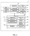
- Fig. 3 is a block diagram illustrating an example of a schematic configuration of the temperature measurement apparatus 1 according to the present embodiment.
- the temperature measurement apparatus 1 includes the first temperature sensor 11, the second temperature sensor 12, a calculation processing unit 300, an operation unit 400, the display unit 13, a sound output unit 600, a communication unit 700, and a storage unit 800.
- the calculation processing unit 300 is a control device and a calculation device which collectively control each unit of the temperature measurement apparatus 1 according to various programs such as a system program stored in the storage unit 800, and is constituted of, for example, a processor such as a central processing unit (CPU) or a digital signal processor (DSP).
- a processor such as a central processing unit (CPU) or a digital signal processor (DSP).
- the calculation processing unit 300 includes a temperature calculation portion 320 and a temperature estimation portion 340 which measure a temperature of the object to be measured as main functional portions, and performs a temperature measurement process which will be described with reference to Fig. 5 , according to a temperature measurement program 810.
- the calculation processing unit 300 also has a clocking function of counting time points and the like.
- the temperature calculation portion 320 changes a display state of the display unit 13, and calculates a temperature according to the above Equation (12) by using detected temperatures indicated by the temperature detection signals from the first temperature sensor 11 and the second temperature sensor 12 before and after the display state is changed.
- the temperature estimation portion 340 estimates a temperature according to Equation (13) by using calculated temperatures which are calculated at different timings, specifically, the previous measurement timing and the present measurement timing by the temperature calculation portion 320.
- the thermal resistance constant R and the thermal capacity constant C, or a value of RxC (hereinafter, collectively referred to as "estimation constants") are initially set and are set as an estimation constant 850 in the storage unit 800.
- the temperature estimation portion 340 is assumed to operate at all times in order to measure a temperature. For this reason, a temperature estimated by the temperature estimation portion 340 is stored in temperature data 830 (refer to Fig. 4 ) of the storage unit 800 as an output temperature which is a measurement result.
- the operation unit 400 is an input device including a switch and the like, and outputs a signal corresponding to the pressed switch to the calculation processing unit 300.
- the operation unit 400 is used to input a set value for initial setting, or to input various instruction operations such as starting and finishing of temperature measurement.
- the display unit 13 is a display device which is constituted of a small-sized display such as a liquid crystal display, an electrophoretic device, or an organic electroluminescent (EL) display, and performs various display based on display signals which are input from the calculation processing unit 300.
- the display unit 13 displays the mark M for measuring an internal temperature, an output temperature which is a measurement result, identification of whether a measurement state is a non-steady state or a steady state, identification of whether or not a measured temperature is abnormal or normal, and the like.
- the sound output unit 600 includes a speaker and reproduces and outputs sound on the basis of a sound signal which is input from the calculation processing unit 300.
- the sound output unit 600 outputs identification sound of whether a measured temperature is abnormal or normal, various notification sounds, and the like.
- the sound mentioned here also includes voice.
- the communication unit 700 is a communication device which transmits and receives information used in the apparatus to and from an external information processing apparatus such as a personal computer (PC) under the control of the calculation processing unit 300.
- an external information processing apparatus such as a personal computer (PC)
- PC personal computer
- various methods may be employed, such as a method of performing wired connection via a cable conforming to a predetermined standard, and a method of performing wireless connection using near field wireless communication.
- the storage unit 800 includes a storage device such as a read only memory (ROM), a flash ROM, and a random access memory (RAM).
- the storage unit 800 stores a system program of the temperature measurement apparatus 1, various programs for realizing various functions such as a temperature calculation function, a temperature estimation function, and a communication function, data, and the like.
- the storage unit 800 stores, as a program, the temperature measurement program 810 which is read by the calculation processing unit 300 and is executed as the temperature measurement process (refer to Fig. 5 ).
- the temperature measurement program 810 includes, as subroutines, a temperature calculation program 812 for calculating a temperature and a temperature estimation program 814 for estimating a temperature according to the above-described principle. The temperature measurement process will be described later in detail with reference to a flowchart.
- the storage unit 800 stores, as data, the temperature data 830, the estimation constant 850, an abnormal temperature condition 870, a normality return condition 880, and a measurement time interval 890.
- the temperature data 830 has, for example, a data structure illustrated in Fig. 4 .
- the temperature data 830 stores identification information for identifying the first state in which the mark M of the display unit 13 is not displayed and the second state in which the mark M is displayed; detected temperatures based on temperature detection signals which are respectively input from the first temperature sensor 11 and the second temperature sensor 12; a calculated temperature which is calculated by using the detected temperatures; an output temperature (output value) which is estimated by using the calculated temperature and is output as a result of the measurement; a measurement state indicating whether a measurement state is a non-steady state or a steady state; and a determination result of whether the output temperature is normal or abnormal, in correlation with each measurement time point. Therefore, the temperature data 830 can be said to be history data of each value.
- the time point indicates a time point (timing) at which a temperature is measured.
- the measurement state is determined on the basis of the progress of a change in a calculated temperature. For example, a temperature change speed is obtained on the basis of a difference between the previous and present calculated temperatures, and a calculation time interval. If the temperature change speed enters a specific value range, a steady state is determined, and otherwise, a non-steady state is determined.
- the abnormal temperature condition 870 is a condition for determining whether or not an output temperature is abnormal.
- the condition is, an OR condition of a high temperature side condition (for example, 38 degrees or higher) and a low temperature side condition (for example, 27 degrees or lower). Abnormality is determined in a case of a high temperature or a low temperature.
- the normality return condition 880 is a condition for determining whether or not an output temperature returns to a normal temperature after abnormality is determined since the abnormal temperature condition 870 is satisfied.
- the normality return condition 880 includes a condition regarding a temperature (return temperature condition) and a condition regarding time (return time condition).
- the return temperature condition is a condition with a threshold value closer to a normal value than a threshold value of the abnormal temperature condition 870.
- the return temperature condition is that a temperature is included in a temperature range from 30 degrees or higher as the low temperature side condition to below 37.5 degrees as the high temperature side condition.
- the return time condition is a condition for determining whether or not a state satisfying the return temperature condition lasts for a predetermined period of time, and one minute or more is defined as the condition.
- the normality return condition 880 is that the duration of the state satisfying the return temperature condition satisfies the return time condition.
- the measurement time interval 890 is a time interval at which temperature measurement is performed.
- the measurement time interval 890 is changed depending on whether a measurement state is a steady state or a non-steady state (transient state) or whether a determination result is normality determination (normal temperature) or abnormality determination (abnormal temperature). Specifically, the time interval is set to be shorter in the non-steady state than in the steady state. The time interval is set to be shorter in the abnormality determination than in the normality determination.
- the time interval 890 may be gradually lengthened up to a predetermined maximum time interval.
- the time interval may be switched to a predetermined minimum time interval, and in a case where the abnormality determination lasts, the time interval may be gradually lengthened up to a predetermined abnormality time interval.
- a measurement time interval may be set to the minimum time interval, and may be gradually lengthened up to a predetermined non-steady time standard time interval according to a period of time for which the non-steady state lasts during the non-steady state. If the time interval is lengthened, power can be saved.
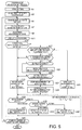
- Fig. 5 is a flowchart illustrating a flow of the temperature measurement process which is performed by the calculation processing unit 300 according to the temperature measurement program 810 stored in the storage unit 800.
- the calculation processing unit 300 performs initial setting (step A1). For example, as a condition of finishing temperature measurement, the number of times of measurement or a time period in which the temperature measurement process lasts may be set.
- the calculation processing unit 300 acquires detected temperatures in the first temperature sensor 11 and the second temperature sensor 12 and stores the detected temperatures in the temperature data 830 (step A3).
- the detected temperatures are the first detected temperatures, and an internal temperature is not calculated.
- the calculation processing unit 300 changes a display state of the display unit 13 (step A5).
- the mark M is displayed, and, in a case where the mark M is displayed in the previous display state, the mark M is not displayed. Consequently, switching between the first display state and the second display state is performed. Since the display state is changed, the calculation processing unit 300 waits without performing another process for a predetermined time period.
- the waiting time period is a time period which is sufficient for the emissivity of the apparatus main body 10 to change, and may be set to, for example, five seconds to five minutes as appropriate depending on a material or the like of the apparatus main body 10.
- the calculation processing unit 300 acquires detected temperatures in the first temperature sensor 11 and the second temperature sensor 12, stores the detected temperatures in the temperature data 830, and calculates an internal temperature by using the present detected temperatures and the detected temperatures at the previous measurement timing (step A7).
- the calculation processing unit 300 estimates an internal temperature by using a calculated temperature which is calculated at the previous measurement timing and a calculated temperature which is calculated at the present measurement timing (step A7).
- the estimated temperature is used as a measurement result at the present measurement timing, and is stored in the temperature data 830 as an output temperature.
- the calculated temperature obtained in the process of obtaining the output temperature is also stored in the temperature data 830 in correlation with a measurement time point.
- the calculation processing unit 300 determines a measurement state on the basis of the progress of the calculated temperature and stores the determined measurement state in the temperature data 830 (step A9).
- the output temperature is displayed on the display unit 13 (step A11). In this case, the determined measurement state may be displayed.
- the calculation processing unit 300 determines that the temperature is abnormal, and performs a notification of the abnormal temperature (step A15). If the output temperature does not satisfy the abnormal temperature condition 870 (NO in step A13), the calculation processing unit 300 determines whether or not the measurement result at the previous measurement timing is abnormality determination (step A17). If the measurement result at the previous measurement timing is abnormality determination (YES in step A17), it is determined whether or not the present output temperature satisfies the return temperature condition of the normality return condition 880 (step A19). Here, if a determination result is negative (NO in step A19), abnormality is determined (step A15). This case indicates that the present output temperature is not abnormal but is determined as being abnormal until it is continuously determined that the present output temperature is not abnormal since the previous determination is abnormality determination.
- step A19 If it is determined that the return temperature condition is satisfied (YES in step A19), the duration of the state determined as satisfying the return temperature condition is measured (steps A21 to A23). In other words, if the duration is not measured, measurement of elapsed time is reset so as to be started again.
- step A25 If the measured elapsed time satisfies the return time condition (YES in step A25), the measurement of the elapsed time is stopped (step A27), the output temperature is determined as returning to a normal temperature, and a notification thereof is performed (step A29). If the return time condition is not satisfied (NO in step A25), the calculation processing unit 300 continuously determines abnormality in a wait-and-see state in step A15.
- step A31 If the previous determination result is not abnormality determination in step A17 (NO in step A17), normality is determined, and a notification thereof is performed (step A31).
- the calculation processing unit 300 sets the measurement time interval 890.
- a measurement state is the non-steady state (the non-steady state in step A33)
- a time interval I t1 is set as the measurement time interval 890 (step A37).
- a time interval I t2 is set as the measurement time interval 890 if a determination result is abnormality determination
- a time interval I t3 is set as the measurement time interval 890 if the determination result is normality determination (steps A39 and A41).
- the time intervals satisfy I t1 ⁇ I t2 ⁇ I t3 .
- the calculation processing unit 300 determines whether or not the temperature measurement process is finished, and if the temperature measurement process is not finished (NO in step A43), the calculation processing unit 300 causes the process to proceed to step A5 when the next measurement timing occurs on the basis of the set measurement time interval 890. If it is determined that the temperature measurement is finished (YES in step A43), the calculation processing unit 300 finishes the temperature measurement process.
- the first temperature sensor 11 is disposed so as to be close to the contact surface 10b of the object to be measured
- the second temperature sensor 12 is disposed so as to be close to the display unit 13.
- An internal temperature of the object to be measured is calculated by using the first state first temperature detected by the first temperature sensor 11 and the first state second temperature detected by the second temperature sensor 12 when the display unit 13 is in the first display state, and the second state first temperature detected by the first temperature sensor 11 and the second state second temperature detected by the second temperature sensor 12 when the display unit 13 is in the second display state.
- the emissivity is changed by making a display state of the display unit 13 differ. Consequently, the heat balance characteristics obtained via the apparatus main body 10 are changed, and thus a temperature of the position of at least the second temperature sensor 12 is changed.
- the internal temperature is calculated by using Equation (12). Consequently, since the heat balance characteristics are not required to be determined, it is possible to obtain an accurate internal temperature of the object to be measured.
- the second temperature sensor 12 is positioned under the mark M whose display color is changed according to the first display state and the second display state.
- the second temperature sensor 12 can be greatly influenced by a change of the emissivity as a result of the display state of the display unit 13 being changed.
- a temperature in a steady state is “estimated” from a temperature which is temporarily “calculated” in consideration of a case of a non-steady state (transient state) in which a temperature of the apparatus main body 10 does not reach the steady state.
- a non-steady state in which a temperature of the apparatus main body 10 does not reach the steady state.
- the temperature measurement apparatus 1 has been described as a wearable apparatus which is mounted on and is fixed to a human body with the bands 20 and 20, but may be configured as smart glasses.
- the first temperature sensor 11 and the second temperature sensor 12 are built into a portion which is in contact with the skin, such as moderns (front cells) or temples of a glasses frame, and a display screen is provided on an outer surface on an opposite side to the contact surface with the skin. More specifically, in a thickness direction of the portion, the first temperature sensor 11 is provided so as to be close to the contact surface with the skin, and the second temperature sensor 12 is provided so as to be close to a display unit. Control of a display state or calculation of a temperature is the same as in the above-described embodiment.
- two temperature sensors are used, but three or more temperature sensors may be used.
- a plurality of temperature sensors are disposed around the position of the above-described first temperature sensor 11, and, among detected temperatures in the temperature sensors, a median or a mean value is used as a detected temperature of the position of the first temperature sensor 11.
- a plurality of temperature sensors are disposed around the position of the above-described second temperature sensor 12, and, among detected temperatures in the temperature sensors, a median or a mean value is used as a detected temperature of the position of the second temperature sensor 12.
Landscapes
- Physics & Mathematics (AREA)
- Health & Medical Sciences (AREA)
- Life Sciences & Earth Sciences (AREA)
- General Physics & Mathematics (AREA)
- Heart & Thoracic Surgery (AREA)
- Surgery (AREA)
- Engineering & Computer Science (AREA)
- Biomedical Technology (AREA)
- Biophysics (AREA)
- Medical Informatics (AREA)
- Molecular Biology (AREA)
- Pathology (AREA)
- Animal Behavior & Ethology (AREA)
- General Health & Medical Sciences (AREA)
- Public Health (AREA)
- Veterinary Medicine (AREA)
- Measuring And Recording Apparatus For Diagnosis (AREA)
- Radiation Pyrometers (AREA)
- Measuring Temperature Or Quantity Of Heat (AREA)
Abstract

Description
- The present invention relates to a temperature measurement apparatus and the like measuring an internal temperature of an object to be measured.
- Biological information such as a health condition, a basal metabolism condition, or a mental condition is obtained on the basis of a body temperature which is fundamentally vital information. In order to determine a health condition, a basal metabolism condition, or a mental condition of a person or an animal on the basis of a body temperature of the person or the animal, information regarding not a temperature of a surface layer of the person or the animal but rather an internal temperature (deep part temperature) thereof is necessary.
- For example, in a case where an internal temperature of a furnace or a pipe is measured, if a temperature measurement apparatus can be provided outside the furnace or the pipe so as to measure an internal temperature, a facility or members for providing the temperature measurement apparatus inside the furnace or the pipe are not necessary, a cheaper temperature measurement apparatus can be used from the viewpoint of heat resistance, corrosion resistance, and a measurement range, and construction cost can be reduced.
- As techniques regarding measurement of an internal temperature, for example, a technique disclosed in
JP-A-55-29794 JP-A-2006-308538 - The technique disclosed in
JP-A-55-29794 - In the technique disclosed in
JP-A-2006-308538 JP-A-2006-308538 - An advantage of some aspects of the invention is to propose a new method for measuring an internal temperature of an object to be measured.
- A first aspect of the invention is directed to a temperature measurement apparatus including a display unit; a first temperature sensor that is, in a thickness direction of an apparatus main body, disposed so as to be close to a contact surface with an object to be measured; a second temperature sensor that is, in the thickness direction of an apparatus main body, disposed so as to be close to the display unit; and a calculation processing unit that is arranged to calculate an internal temperature of the object to be measured by using a first state first temperature detected by the first temperature sensor and a first state second temperature detected by the second temperature sensor when the display unit is in a first display state, and a second state first temperature detected by the first temperature sensor and a second state second temperature detected by the second temperature sensor when the display unit is in a second display state, the first display state and the second display state differing in emissivity of the surface of the apparatus main body.
- As another aspect of the invention, the invention can be configured as a temperature measurement method for a temperature measurement apparatus including a display unit, a first temperature sensor that is, in a thickness direction of an apparatus main body, disposed so as to be close to a contact surface with an object to be measured, and a second temperature sensor that is, in the thickness direction of the apparatus main body, disposed so as to be close to the display unit, the method including switching the display unit between a first display state and a second display state, the first display state and the second display state differing in emissivity of the surface of the apparatus main body; and calculating an internal temperature of the object to be measured by using a first state first temperature detected by the first temperature sensor and a first state second temperature detected by the second temperature sensor when the display unit is in the first display state, and a second state first temperature detected by the first temperature sensor and a second state second temperature detected by the second temperature sensor when the display unit is in the second display state.
- According to the first aspect and the like of the invention, the first temperature sensor is disposed so as to be close to the contact surface with the object to be measured, and the second temperature sensor is disposed so as to be close to the display unit, in the thickness direction of the apparatus main body. An internal temperature of the obj ect to be measured is calculated by using the first state first temperature detected by the first temperature sensor and the first state second temperature detected by the second temperature sensor when the display unit is in the first display state, and the second state first temperature detected by the first temperature sensor and the second state second temperature detected by the second temperature sensor when the display unit is in the second display state. The emissivity is changed by making a display state differ. Consequently, the heat balance characteristics obtained via the apparatus main body are changed, and thus a temperature of the position of at least the second temperature sensor is changed. As will be described later in detail, it is possible to obtain an accurate internal temperature of the object to be measured without determining heat balance characteristics by using the temperatures obtained in each display state.
- A second aspect of the invention is directed to the temperature measurement apparatus according to the first aspect, in which the second temperature sensor is disposed under a portion of the display unit whose display color is changed in the first display state and the second display state.
- According to the second aspect of the invention, the second temperature sensor can be disposed under a portion of the display unit whose display color is changed in the first display state and the second display state. Consequently, the second temperature sensor can be disposed at a position which is greatly influenced by a change of the emissivity as a result of the display state of the display unit being changed.
- A third aspect of the invention is directed to the temperature measurement apparatus according to the second aspect, in which, in the display unit and the second temperature sensor, an area of the portion of the display unit is larger than an area of the second temperature sensor in a plan view of the display unit.
- In this case, as a fourth aspect of the invention, in the display unit and the second temperature sensor, an area of the portion of the display unit may be three times larger or more than an area of the second temperature sensor in a plan view of the display unit.
- According to the third and fourth aspects of the invention, the second temperature sensor can be more greatly influenced by a change of the emissivity as a result of the display state of the display unit being changed.
- A fifth aspect of the invention is directed to the temperature measurement apparatus according to any one of the first to fourth aspects, in which the first temperature sensor and the second temperature sensor are disposed at positions to which distances from an outer edge or the center of the apparatus main body are different from each other in a plan view of the display unit.
- According to the fifth aspect of the invention, the heat balance characteristics can be made to be different from each other at the respective installation positions of the first temperature sensor and the second temperature sensor.
- Regarding a specific method of calculating an internal temperature, as a sixth aspect of the invention, the calculation processing unit is arranged to calculate an internal temperature of the object to be measured on the basis of the following equation.

- Here, Tc indicates an internal temperature, Ta1 indicates the first state first temperature, Ta2 indicates the second state first temperature, Tb1 indicates the first state second temperature, and the Tb2 indicates the second state second temperature.
- A seventh aspect of the invention is directed to the temperature measurement apparatus according to any one of the first to sixth aspects, in which the object to be measured is a human body, and the temperature measurement apparatus is configured as a wearable apparatus.
- According to the seventh aspect of the invention, the temperature measurement apparatus can be configured as a wearable apparatus, and thus a body temperature of a user can be measured anywhere and anytime.
- In relation to the display unit, some configurations may be employed. For example, as an eighth aspect of the invention, the display unit may include a liquid crystal display, and, as a ninth aspect of the invention, the display unit may include an electrophoretic device.
- The invention will be described with reference to the accompanying drawings, wherein like numbers reference like elements.
-
Figs. 1A to 1C are diagrams for explaining a principle of temperature calculation. -
Figs. 2A to 2C are diagrams illustrating a configuration of a temperature measurement apparatus. -
Fig. 3 is a block diagram illustrating a function of the temperature measurement apparatus. -
Fig. 4 is a diagram illustrating an example of a structure of temperature data. -
Fig. 5 is a flowchart illustrating a flow of a temperature measurement process. - In the present embodiment, a description will be made assuming that an object to be measured is a human body, and an internal temperature of the human body is measured. Measurement of a temperature includes two types. In other words, one is "calculation" of a temperature, and the other is "estimation" of a temperature. The "calculation" will be first described, and then the "estimation" will be described.
-
Figs. 1A to 1C are diagrams for explaining a principle of the temperature calculation in the present embodiment. In the present embodiment, as illustrated inFig. 1A , abase 100 is brought into contact with an object to be measured so that a contact surface ST is brought into contact with the object to be measured which is a temperature measurement target. - The
base 100 has thermal conductivity, and is configured to include a plurality of temperature sensors at different positions inside thebase 100. Thebase 100 is made of a material having a predetermined thermal conductivity (or thermal resistance). - In the present embodiment, temperature sensors are provided at two different positions in the
base 100. Hereinafter, the two temperature sensors will be referred to as afirst temperature sensor 11 and asecond temperature sensor 12. As illustrated, positions where thefirst temperature sensor 11 and thesecond temperature sensor 12 detect a temperature will be respectively referred to as a first detection position P1 and a second detection position P2. - As the temperature sensor, a well-known sensor may be employed. For example, a sensor using a chip thermistor, a flexible board in which a thermistor pattern is printed, or a platinum temperature measuring resistor, or a sensor using a thermocouple element, a PN junction element, or a diode may be employed. An electric signal (hereinafter, referred to as a "temperature detection signal") corresponding to a temperature of the detection position is output from the temperature sensor, and a temperature detected by each temperature sensor is acquired on the basis of the temperature detection signal. Therefore, the temperature detection signal can be said to be equivalent to a detected temperature.
- A position as a temperature measurement target of the object to be measured is referred to as a "measurement target position". Any position in the external world is referred to as "any external position". In the present embodiment, the object to be measured is the human body, but may be organic objects (living bodies) such as animals other than the human body, or may be inorganic objects such as a furnace, a pipe, and an engine. The external world indicates a measurement environment in which the object to be measured is placed.
- It is assumed that an internal temperature of the human body is higher than an external temperature. Heat moves from a high temperature side to a low temperature side. For this reason, herein, for example, there may be a heat flow passage with a measurement target position PC as a heat source and any external position Pout as a finish point. More specifically, there may be two heat flow passages including a heat flow passage (hereinafter, referred to as a "first heat flow passage") which reaches any external position Pout from the measurement target position PC via the first detection position P1, and a heat flow passage (hereinafter, referred to as a "second heat flow passage") which reaches any external position Pout from the measurement target position PC via the second detection position P2.
- When heat flows along the first and the second heat flow passages, a procedure thereof is influenced by the inflow of heat from the external world and the outflow to the external world. In the present embodiment, the heat exchange is referred to as "heat balance". If the above-described heat flow passages are modeled in terms of electrical circuits by taking into consideration such heat balance, a heat flow passage model as illustrated in
Fig. 1B can be built. - In the heat flow passage model illustrated in
Fig. 1B , various passages may be considered as passages from the measurement target position PC to the first detection position P1, and various passages may also be considered as passages from the first detection position P1 to any external position Pout. In the heat flow passage model illustrated inFig. 1B , each passage is represented as a resistor. This is also the same for the second heat flow passage. Of course, a value of each thermal resistor is not known. - If the heat flow passage model illustrated in
Fig. 1B is simplified, models are obtained as illustrated inFig. 1C . A thermal resistor obtained by combining the thermal resistors connected in parallel between the measurement target position PC and the first detection position P1 is indicated by Ra1, and a thermal resistor obtained by combining the thermal resistors connected in parallel between the first detection position P1 and any external position Pout is indicated by Ra2. A thermal resistor obtained by combining the thermal resistors connected in parallel between the measurement target position PC and the second detection position P2 is indicated by Rb1, and a thermal resistor obtained by combining the thermal resistors connected in parallel between the second detection position P2 and any external position Pout is indicated by Rb2. - A temperature of the measurement target position PC is referred to as an "internal temperature" and is indicated by Tc. A temperature of any external position Pout is referred to as an "external temperature" and is indicated by Tout. Detected temperatures in the
first temperature sensor 11 and thesecond temperature sensor 12 are respectively referred to as a "first detected temperature" and a "second detected temperature", and are indicated by Ta and Tb. - In the heat flow passage model illustrated in
Fig. 1C , the first detected temperature Ta may be represented as in the following Equation (1) by using the thermal resistors Ra1 and Ra2, the internal temperature Tc, and the external temperature Tout. The second detected temperature Tb may be represented as in the following Equation (2) by using the thermal resistors Rb1 and Rb2, the internal temperature Tc, and the external temperature Tout.

- In order to obtain the internal temperature Tc, the terms of the external temperature Tout are removed from Equations (1) and (2). As shown in the following Equation (3), the coefficient of the external temperature Tout in Equation (1) and the coefficient of the external temperature Tout in Equation (2) are respectively replaced as in the following Equations (3) and (4).


- The coefficient a is represented by a proportion of the thermal resistor Ra1 to all the thermal resistors of the first heat flow passage. This indicates an influence of the heat balance which a heat flow traveling along the first heat flow passage receives from the thermal resistor Ra1, and may be considered as a coefficient indicating heat balance characteristics at the first detection position P1. This is also the same for the coefficient b.
- In this case, Equations (1) and (2) may be respectively rewritten as the following Equations (5) and (6).


- Therefore, the internal temperature Tc may be expressed as in Equation (7) from Equations (5) and (6).

- Here, as a ratio between the coefficient a defined by Equation (3) and the coefficient b defined by Equation (4), a heat balance relative coefficient D expressed by the following Equation (8) is introduced.

- The heat balance relative coefficient D is a coefficient (a relative value of the coefficient a and the coefficient b) indicating a relative relationship between the respective heat balance characteristics at the first detection position P1 and the second detection position P2. In this case, Equation (7) may be rewritten into Equation (9) by using the heat balance relative coefficient D.

- If Equation (9) is solved for the heat balance relative coefficient D, the following Equation (10) is obtained.

- As can be seen from Equation (10), the heat balance relative coefficient D is calculated by using a difference between a temperature detected by the
first temperature sensor 11 and the internal temperature Tc of the object to be measured and a difference between the temperature detected by thesecond temperature sensor 12 and the internal temperature Tc of the object to be measured. The internal temperature Tc of the object to be measured is a measurement target temperature, and a value thereof is unknown. - However, it is assumed that the heat balance characteristics in the heat flow passages can be changed in a state in which there is no change in the internal temperature Tc and the external temperature Tout. Then, the following Equation (11) is established. Here, a state before the heat balance characteristics are changed is referred to as a "first state"; a state after the heat balance characteristics are changed is referred to as a "second state"; a detected temperature in the
first temperature sensor 11 before the heat balance characteristics are changed is referred to as a first state first temperature Ta1; a detected temperature in thesecond temperature sensor 12 before the heat balance characteristics are changed is referred to as a first state second temperature Tb1; a detected temperature in thefirst temperature sensor 11 after the heat balance characteristics are changed is referred to as a second state first temperature Ta2; and a detected temperature in thesecond temperature sensor 12 after the heat balance characteristics are changed is referred to as a second state second temperature Tb2.
- If the heat balance relative coefficient D is removed from Equation (11), the following Equation (12) is obtained. In other words, the heat balance relative coefficient D is still unknown, and the internal temperature Tc can be directly obtained without using the heat balance relative coefficient D. Therefore, it is possible to calculate the internal temperature Tc with high accuracy.

- The above description relates to the "calculation" of a temperature.
- An internal temperature of an object to be measured can be calculated according to the above-described principle of temperature calculation, but some time is required after the
base 100 is brought into contact with the object to be measured until a temperature (that is, a temperature of the installation position of the temperature sensor) inside thebase 100 is stabilized and reaches a steady state. Since the first detected temperature Ta in thefirst temperature sensor 11 and the second detected temperature Tb in thesecond temperature sensor 12 change during a transient state before the steady state, even if the internal temperature Tc is obtained according to Equation (12) by using the first detected temperature Ta and the second detected temperature Tb obtained previously, there is a concern that an error may be included in the calculated temperature. - Therefore, a technique for estimating a temperature in the steady state from a temperature in the transient state is introduced. Specifically, in the present embodiment, an expression of non-steady thermal conduction is used which is obtained from a thermal conduction equation. If, as temperatures calculated with time differences, the internal temperature Tc calculated at a time point t1 is referred to as a first internal temperature Tc1, and the internal temperature Tc calculated at a time point t2 is referred to as a second internal temperature Tc2, a steady internal temperature TcX can be estimated by using the following Equation (13). This operation is the "estimation" of a temperature.

- Here, R is a thermal resistance constant and is predefined, and C is a thermal capacity constant and is predefined. Instead of each of the thermal resistance constant R and the thermal capacity constant C being predefined, a value of RxC may be predefined.
- In the "estimation" process, a temperature can be effectively obtained not only in the transient state (non-steady state) but also in the steady state. For this reason, in the present embodiment, a temperature obtained during the "estimation" process is assumed to be output as an internal temperature (output value) of an object to be measured at all times. However, in a case where a predetermined stabilization condition in which a change in a "calculated" temperature is not considerable is satisfied, the "estimation" process may be omitted, and the "calculated" temperature may be used as an output value.
- Next, a description will be made of Examples of a
temperature measurement apparatus 1 which measures an internal temperature of a human body which is an object to be measured according to the above-described principle. -
Fig. 2A is an exterior view illustrating the entire configuration example of thetemperature measurement apparatus 1. In the present example, thetemperature measurement apparatus 1 is configured as a wristwatch type wearable apparatus mounted on the arm of a user who is an object to be measured and is a human body by fastening twobands main body 10 with abuckle 21. The twobands main body 10 can be brought into close contact with a skin surface of the user. A mounting part is not limited to the arm, and thetemperature measurement apparatus 1 may be mounted on a skin surface of another part such as the chest, the abdomen, the neck, the thigh, or the ankle. Thetemperature measurement apparatus 1 may reach the upper arm from the wrist. Thebands 20 may be lengthened, a part of thebands 20 may be made of an elastic material, or a hook-and-loop fastener may be used instead of thebuckle 21, according to mounting parts. Of course, also in the present embodiment, the hook-and-loop fastener may be used instead of thebuckle 21. - The
temperature measurement apparatus 1 includes adisplay unit 13 which has a display surface on a surface side (a side directed outward when a user wears the temperature measurement apparatus 1) of the apparatusmain body 10, and anoperation switch 16 as an operation input unit. The user can perform various input operations such as a measurement starting operation by operating theoperation switch 16. A chargingtype battery 15 and acontrol board 17 are built into the apparatusmain body 10. Although not illustrated, a communication device for transmitting a result of measuring an internal temperature to an external apparatus, a reader/writer device for reading and writing a measurement result from and to a memory card, and the like are provided at proper locations of the apparatusmain body 10 as appropriate. - A method of charging the
battery 15 may be set as appropriate. For example, there may be a configuration in which an electrical contact is separately provided on a rear surface side of the apparatusmain body 10 and is set in a cradle connected to a household power supply, and thebattery 15 is charged via the electrical contact and the cradle, and there may be a configuration in which thebattery 15 may be charged in a non-contact wireless manner. - The
control board 17 is mounted with a central processing unit (CPU) 171, and astorage medium 173 which is a storage element such as an integrated circuit (IC) memory. In addition, thecontrol board 17 may be mounted with necessary electronic components such as an application specific integrated circuit (ASIC), a field-programmable gate array (FPGA), and various integrated circuits as appropriate. Thetemperature measurement apparatus 1 realizes various functions such as an internal temperature measurement function by theCPU 171 executing a program stored in thestorage medium 173. - The
display unit 13 is constituted of a small-sized display such as a liquid crystal display, an electrophoretic device, or an organic electroluminescent (EL) display. Thedisplay unit 13 may have a touch panel function. -
Fig. 2B is a schematic diagram for explaining positions where thefirst temperature sensor 11 and thesecond temperature sensor 12 are disposed in a sectional view in a thickness direction of the apparatusmain body 10. In the thickness direction of the apparatusmain body 10, thefirst temperature sensor 11 is disposed so as to be close to acontact surface 10b which is the rear surface of the apparatusmain body 10 which is in contact with the user' s skin, and thesecond temperature sensor 12 is disposed so as to be close to thedisplay unit 13. More specifically, thefirst temperature sensor 11 is disposed at a position closer to thecontact surface 10b than thedisplay unit 13 , and thesecond temperature sensor 12 is disposed at a position closer to thedisplay unit 13 than thecontact surface 10b. -
Fig. 2C is a diagram for explaining a positional relationship between adisplay surface 13a of thedisplay unit 13, and thefirst temperature sensor 11 and thesecond temperature sensor 12 in a plan view of the apparatusmain body 10. Thedisplay unit 13 has a designated portion at which a mark M indicating that a display state is changed in order to measure an internal temperature is displayed. Thesecond temperature sensor 12 is positioned under the display portion of the mark M, and thefirst temperature sensor 11 is disposed far from the mark M. - In a situation in which an internal temperature of the human body is higher than an external temperature, a heat flow passage is formed in which heat dissipates from the human body via the apparatus
main body 10. At this time, since heat dissipates via the surface of the apparatusmain body 10, if the emissivity of the surface of the apparatusmain body 10 is changed, dissipating heat is also changed. That is, in the present example, the emissivity is changed by changing a display state of thedisplay unit 13, so as to change the heat balance characteristics. In the present example, the mark M indicates a change of a display state. - Particularly, the present example is characterized in that the
second temperature sensor 12 is positioned between the skin surface of the user and the mark M directly under the mark M. For this reason, a heat flow passage including the arrangement position of thesecond temperature sensor 12 is greatly influenced by a change of the emissivity when the mark M is displayed or not displayed, and thus the heat balance characteristics are influenced. As a result, it is possible to cause the "first state" and the "second state" described in the principle to relatively easily occur through display or non-display of the mark M. - In the present example, as illustrated in
Fig. 2C , an area of the mark M in a plan view is three times or more than an area of thesecond temperature sensor 12 so that the influence of the change of the emissivity is further exhibited. Thesecond temperature sensor 12 is provided directly under the mark M at substantially the center thereof. - As illustrated in
Fig. 2C , thefirst temperature sensor 11 and thesecond temperature sensor 12 are disposed at the positions to which distances from the outer edge and the center of the apparatusmain body 10 are different from each other in a plan view. Consequently, resistances related to the outflow of heat at the respective positions of thefirst temperature sensor 11 and thesecond temperature sensor 12 can be made different from each other, and thus detected temperatures in thefirst temperature sensor 11 and thesecond temperature sensor 12 can be made different from each other in the steady state. - In the present example, the
first temperature sensor 11 and thesecond temperature sensor 12 are disposed at positions to which distances from the outer edge and the center of the apparatusmain body 10 are different from each other, but either distances from the outer edge of the apparatusmain body 10 or distances from the center of the apparatusmain body 10 may be different from each other in a plan view. - In the present example, a change of a display state is indicated by display or non-display of the mark M, but other display forms may be employed, such as switching between black display and white display in the entire surface or 1/4 of the lower left screen of the
display surface 13a. -
Fig. 3 is a block diagram illustrating an example of a schematic configuration of thetemperature measurement apparatus 1 according to the present embodiment. Thetemperature measurement apparatus 1 includes thefirst temperature sensor 11, thesecond temperature sensor 12, acalculation processing unit 300, anoperation unit 400, thedisplay unit 13, asound output unit 600, acommunication unit 700, and astorage unit 800. - The
calculation processing unit 300 is a control device and a calculation device which collectively control each unit of thetemperature measurement apparatus 1 according to various programs such as a system program stored in thestorage unit 800, and is constituted of, for example, a processor such as a central processing unit (CPU) or a digital signal processor (DSP). - The
calculation processing unit 300 includes atemperature calculation portion 320 and atemperature estimation portion 340 which measure a temperature of the object to be measured as main functional portions, and performs a temperature measurement process which will be described with reference toFig. 5 , according to atemperature measurement program 810. Thecalculation processing unit 300 also has a clocking function of counting time points and the like. - The
temperature calculation portion 320 changes a display state of thedisplay unit 13, and calculates a temperature according to the above Equation (12) by using detected temperatures indicated by the temperature detection signals from thefirst temperature sensor 11 and thesecond temperature sensor 12 before and after the display state is changed. - The
temperature estimation portion 340 estimates a temperature according to Equation (13) by using calculated temperatures which are calculated at different timings, specifically, the previous measurement timing and the present measurement timing by thetemperature calculation portion 320. The thermal resistance constant R and the thermal capacity constant C, or a value of RxC (hereinafter, collectively referred to as "estimation constants") are initially set and are set as an estimation constant 850 in thestorage unit 800. - In the present example, the
temperature estimation portion 340 is assumed to operate at all times in order to measure a temperature. For this reason, a temperature estimated by thetemperature estimation portion 340 is stored in temperature data 830 (refer toFig. 4 ) of thestorage unit 800 as an output temperature which is a measurement result. - The
operation unit 400 is an input device including a switch and the like, and outputs a signal corresponding to the pressed switch to thecalculation processing unit 300. Theoperation unit 400 is used to input a set value for initial setting, or to input various instruction operations such as starting and finishing of temperature measurement. - The
display unit 13 is a display device which is constituted of a small-sized display such as a liquid crystal display, an electrophoretic device, or an organic electroluminescent (EL) display, and performs various display based on display signals which are input from thecalculation processing unit 300. Thedisplay unit 13 displays the mark M for measuring an internal temperature, an output temperature which is a measurement result, identification of whether a measurement state is a non-steady state or a steady state, identification of whether or not a measured temperature is abnormal or normal, and the like. - The
sound output unit 600 includes a speaker and reproduces and outputs sound on the basis of a sound signal which is input from thecalculation processing unit 300. Thesound output unit 600 outputs identification sound of whether a measured temperature is abnormal or normal, various notification sounds, and the like. The sound mentioned here also includes voice. - The
communication unit 700 is a communication device which transmits and receives information used in the apparatus to and from an external information processing apparatus such as a personal computer (PC) under the control of thecalculation processing unit 300. As a communication method of thecommunication unit 700, various methods may be employed, such as a method of performing wired connection via a cable conforming to a predetermined standard, and a method of performing wireless connection using near field wireless communication. - The
storage unit 800 includes a storage device such as a read only memory (ROM), a flash ROM, and a random access memory (RAM). Thestorage unit 800 stores a system program of thetemperature measurement apparatus 1, various programs for realizing various functions such as a temperature calculation function, a temperature estimation function, and a communication function, data, and the like. - The
storage unit 800 stores, as a program, thetemperature measurement program 810 which is read by thecalculation processing unit 300 and is executed as the temperature measurement process (refer toFig. 5 ). Thetemperature measurement program 810 includes, as subroutines, atemperature calculation program 812 for calculating a temperature and atemperature estimation program 814 for estimating a temperature according to the above-described principle. The temperature measurement process will be described later in detail with reference to a flowchart. - The
storage unit 800 stores, as data, thetemperature data 830, the estimation constant 850, anabnormal temperature condition 870, anormality return condition 880, and ameasurement time interval 890. - The
temperature data 830 has, for example, a data structure illustrated inFig. 4 . In other words, thetemperature data 830 stores identification information for identifying the first state in which the mark M of thedisplay unit 13 is not displayed and the second state in which the mark M is displayed; detected temperatures based on temperature detection signals which are respectively input from thefirst temperature sensor 11 and thesecond temperature sensor 12; a calculated temperature which is calculated by using the detected temperatures; an output temperature (output value) which is estimated by using the calculated temperature and is output as a result of the measurement; a measurement state indicating whether a measurement state is a non-steady state or a steady state; and a determination result of whether the output temperature is normal or abnormal, in correlation with each measurement time point. Therefore, thetemperature data 830 can be said to be history data of each value. - Here, the time point indicates a time point (timing) at which a temperature is measured. The measurement state is determined on the basis of the progress of a change in a calculated temperature. For example, a temperature change speed is obtained on the basis of a difference between the previous and present calculated temperatures, and a calculation time interval. If the temperature change speed enters a specific value range, a steady state is determined, and otherwise, a non-steady state is determined.
- In
Fig. 4 , at a first time point "T1", only a detected temperature in the first detection in which a display state is constant is obtained, thus a temperature cannot be calculated, and all the columns of the calculated temperature, the output temperature, the measurement state, and the determination result are vacant. - Referring to
Fig. 3 again, theabnormal temperature condition 870 is a condition for determining whether or not an output temperature is abnormal. For example, the condition is, an OR condition of a high temperature side condition (for example, 38 degrees or higher) and a low temperature side condition (for example, 27 degrees or lower). Abnormality is determined in a case of a high temperature or a low temperature. - The
normality return condition 880 is a condition for determining whether or not an output temperature returns to a normal temperature after abnormality is determined since theabnormal temperature condition 870 is satisfied. Thenormality return condition 880 includes a condition regarding a temperature (return temperature condition) and a condition regarding time (return time condition). The return temperature condition is a condition with a threshold value closer to a normal value than a threshold value of theabnormal temperature condition 870. For example, the return temperature condition is that a temperature is included in a temperature range from 30 degrees or higher as the low temperature side condition to below 37.5 degrees as the high temperature side condition. The return time condition is a condition for determining whether or not a state satisfying the return temperature condition lasts for a predetermined period of time, and one minute or more is defined as the condition. Thus, thenormality return condition 880 is that the duration of the state satisfying the return temperature condition satisfies the return time condition. - The
measurement time interval 890 is a time interval at which temperature measurement is performed. Themeasurement time interval 890 is changed depending on whether a measurement state is a steady state or a non-steady state (transient state) or whether a determination result is normality determination (normal temperature) or abnormality determination (abnormal temperature). Specifically, the time interval is set to be shorter in the non-steady state than in the steady state. The time interval is set to be shorter in the abnormality determination than in the normality determination. - Setting of the
measurement time interval 890 is not limited thereto. In a case where the normality determination or the steady state lasts, the time interval may be gradually lengthened up to a predetermined maximum time interval. In a case where a determination result changes from the normality determination to the abnormality determination, the time interval may be switched to a predetermined minimum time interval, and in a case where the abnormality determination lasts, the time interval may be gradually lengthened up to a predetermined abnormality time interval. When measurement is started, a measurement time interval may be set to the minimum time interval, and may be gradually lengthened up to a predetermined non-steady time standard time interval according to a period of time for which the non-steady state lasts during the non-steady state. If the time interval is lengthened, power can be saved. -
Fig. 5 is a flowchart illustrating a flow of the temperature measurement process which is performed by thecalculation processing unit 300 according to thetemperature measurement program 810 stored in thestorage unit 800. - First, the
calculation processing unit 300 performs initial setting (step A1). For example, as a condition of finishing temperature measurement, the number of times of measurement or a time period in which the temperature measurement process lasts may be set. - Next, the
calculation processing unit 300 acquires detected temperatures in thefirst temperature sensor 11 and thesecond temperature sensor 12 and stores the detected temperatures in the temperature data 830 (step A3). The detected temperatures are the first detected temperatures, and an internal temperature is not calculated. - Next, the
calculation processing unit 300 changes a display state of the display unit 13 (step A5). In a case where the mark M is not displayed in the previous display state, the mark M is displayed, and, in a case where the mark M is displayed in the previous display state, the mark M is not displayed. Consequently, switching between the first display state and the second display state is performed. Since the display state is changed, thecalculation processing unit 300 waits without performing another process for a predetermined time period. The waiting time period is a time period which is sufficient for the emissivity of the apparatusmain body 10 to change, and may be set to, for example, five seconds to five minutes as appropriate depending on a material or the like of the apparatusmain body 10. - Next, the
calculation processing unit 300 acquires detected temperatures in thefirst temperature sensor 11 and thesecond temperature sensor 12, stores the detected temperatures in thetemperature data 830, and calculates an internal temperature by using the present detected temperatures and the detected temperatures at the previous measurement timing (step A7). Thecalculation processing unit 300 estimates an internal temperature by using a calculated temperature which is calculated at the previous measurement timing and a calculated temperature which is calculated at the present measurement timing (step A7). The estimated temperature is used as a measurement result at the present measurement timing, and is stored in thetemperature data 830 as an output temperature. The calculated temperature obtained in the process of obtaining the output temperature is also stored in thetemperature data 830 in correlation with a measurement time point. - Next, the
calculation processing unit 300 determines a measurement state on the basis of the progress of the calculated temperature and stores the determined measurement state in the temperature data 830 (step A9). The output temperature is displayed on the display unit 13 (step A11). In this case, the determined measurement state may be displayed. - If the output temperature satisfies the abnormal temperature condition 870 (YES in step A13), the
calculation processing unit 300 determines that the temperature is abnormal, and performs a notification of the abnormal temperature (step A15). If the output temperature does not satisfy the abnormal temperature condition 870 (NO in step A13), thecalculation processing unit 300 determines whether or not the measurement result at the previous measurement timing is abnormality determination (step A17). If the measurement result at the previous measurement timing is abnormality determination (YES in step A17), it is determined whether or not the present output temperature satisfies the return temperature condition of the normality return condition 880 (step A19). Here, if a determination result is negative (NO in step A19), abnormality is determined (step A15). This case indicates that the present output temperature is not abnormal but is determined as being abnormal until it is continuously determined that the present output temperature is not abnormal since the previous determination is abnormality determination. - If it is determined that the return temperature condition is satisfied (YES in step A19), the duration of the state determined as satisfying the return temperature condition is measured (steps A21 to A23). In other words, if the duration is not measured, measurement of elapsed time is reset so as to be started again.
- If the measured elapsed time satisfies the return time condition (YES in step A25), the measurement of the elapsed time is stopped (step A27), the output temperature is determined as returning to a normal temperature, and a notification thereof is performed (step A29). If the return time condition is not satisfied (NO in step A25), the
calculation processing unit 300 continuously determines abnormality in a wait-and-see state in step A15. - If the previous determination result is not abnormality determination in step A17 (NO in step A17), normality is determined, and a notification thereof is performed (step A31).
- After any one of steps A15, A29, and A31, the
calculation processing unit 300 sets themeasurement time interval 890. In other words, if a measurement state is the non-steady state (the non-steady state in step A33), a time interval It1 is set as the measurement time interval 890 (step A37). In a case where the measurement state is the steady state (the steady state in step A33), a time interval It2 is set as themeasurement time interval 890 if a determination result is abnormality determination, and a time interval It3 is set as themeasurement time interval 890 if the determination result is normality determination (steps A39 and A41). The time intervals satisfy It1<It2<It3. - The
calculation processing unit 300 determines whether or not the temperature measurement process is finished, and if the temperature measurement process is not finished (NO in step A43), thecalculation processing unit 300 causes the process to proceed to step A5 when the next measurement timing occurs on the basis of the setmeasurement time interval 890. If it is determined that the temperature measurement is finished (YES in step A43), thecalculation processing unit 300 finishes the temperature measurement process. - As described above, according to the
temperature measurement apparatus 1, in the thickness direction of the apparatusmain body 10, thefirst temperature sensor 11 is disposed so as to be close to thecontact surface 10b of the object to be measured, and thesecond temperature sensor 12 is disposed so as to be close to thedisplay unit 13. An internal temperature of the object to be measured is calculated by using the first state first temperature detected by thefirst temperature sensor 11 and the first state second temperature detected by thesecond temperature sensor 12 when thedisplay unit 13 is in the first display state, and the second state first temperature detected by thefirst temperature sensor 11 and the second state second temperature detected by thesecond temperature sensor 12 when thedisplay unit 13 is in the second display state. The emissivity is changed by making a display state of thedisplay unit 13 differ. Consequently, the heat balance characteristics obtained via the apparatusmain body 10 are changed, and thus a temperature of the position of at least thesecond temperature sensor 12 is changed. - The internal temperature is calculated by using Equation (12). Consequently, since the heat balance characteristics are not required to be determined, it is possible to obtain an accurate internal temperature of the object to be measured.
- The
second temperature sensor 12 is positioned under the mark M whose display color is changed according to the first display state and the second display state. Thus, thesecond temperature sensor 12 can be greatly influenced by a change of the emissivity as a result of the display state of thedisplay unit 13 being changed. - In the temperature measurement, a temperature in a steady state is "estimated" from a temperature which is temporarily "calculated" in consideration of a case of a non-steady state (transient state) in which a temperature of the apparatus
main body 10 does not reach the steady state. Thus, it is possible to obtain a highly accurate internal temperature even in the non-steady state (transient state) in which the apparatusmain body 10 has just come into contact with a skin surface. - An example of the embodiment to which the invention is applied has been described, but an embodiment to which the invention is applicable is not limited to the above-described embodiment.
- For example, the
temperature measurement apparatus 1 has been described as a wearable apparatus which is mounted on and is fixed to a human body with thebands first temperature sensor 11 and thesecond temperature sensor 12 are built into a portion which is in contact with the skin, such as moderns (front cells) or temples of a glasses frame, and a display screen is provided on an outer surface on an opposite side to the contact surface with the skin. More specifically, in a thickness direction of the portion, thefirst temperature sensor 11 is provided so as to be close to the contact surface with the skin, and thesecond temperature sensor 12 is provided so as to be close to a display unit. Control of a display state or calculation of a temperature is the same as in the above-described embodiment. - In the above-described embodiment, two temperature sensors are used, but three or more temperature sensors may be used. For example, a plurality of temperature sensors are disposed around the position of the above-described
first temperature sensor 11, and, among detected temperatures in the temperature sensors, a median or a mean value is used as a detected temperature of the position of thefirst temperature sensor 11. Similarly, a plurality of temperature sensors are disposed around the position of the above-describedsecond temperature sensor 12, and, among detected temperatures in the temperature sensors, a median or a mean value is used as a detected temperature of the position of thesecond temperature sensor 12.
Claims (10)
- A temperature measurement apparatus (1) comprising:a display unit (13);a first temperature sensor (11) that is, in a thickness direction of an apparatus main body (10), disposed so as to be close to a contact surface with an object to be measured;a second temperature sensor (12) that is, in the thickness direction of the apparatus main body, disposed so as to be close to the display unit; anda calculation processing unit (300) that is arranged to calculate an internal temperature of the object to be measured by using a first state first temperature detected by the first temperature sensor (11) and a first state second temperature detected by the second temperature sensor (12) when the display unit (13) is in a first display state, and a second state first temperature detected by the first temperature sensor (11) and a second state second temperature detected by the second temperature sensor (12) when the display unit (13) is in a second display state, the first display state and the second display state differing in emissivity of the surface of the apparatus main body (10).
- The temperature measurement apparatus (1) according to claim 1,
wherein the second temperature sensor (12) is disposed under a portion (M) of the display unit (13) whose display color is changed in the first display state and the second display state. - The temperature measurement apparatus (1) according to claim 2,
wherein, in the display unit (13) and the second temperature sensor (12), an area (M) of the portion of the display unit (13) is larger than an area of the second temperature sensor (12) in a plan view of the display unit. - The temperature measurement apparatus (1) according to claim 3,
wherein, in the display unit (13) and the second temperature sensor (12), an area (M) of the portion of the display unit (13) is three times larger or more than an area of the second temperature sensor in a plan view of the display unit. - The temperature measurement apparatus (1) according to one of claims 1 to 4,
wherein the first temperature sensor (11) and the second temperature sensor (12) are disposed at positions to which distances from an outer edge or the center of the apparatus main body (10) are different from each other in a plan view of the display unit (13). - The temperature measurement apparatus (1) according to one of the preceding claims,
wherein the calculation processing unit (300) is arranged to calculate an internal temperature of the object to be measured on the basis of the following equation:
- The temperature measurement apparatus (1) according to one of the preceding claims,
wherein the object to be measured is a human body, and
wherein the temperature measurement apparatus (1) is configured as a wearable apparatus. - The temperature measurement apparatus (1) according to one of the preceding claims,
wherein the display unit (13) includes a liquid crystal display. - The temperature measurement apparatus (1) according to one of claims 1 to 7,
wherein the display unit (13) includes an electrophoretic device. - A temperature measurement method for a temperature measurement apparatus (1) including a display unit (13), a first temperature sensor (11) that is, in a thickness direction of an apparatus main body (10), disposed so as to be close to a contact surface with an object to be measured, and a second temperature sensor (12) that is, in the thickness direction of the apparatus main body (10), disposed so as to be close to the display unit (13), the method comprising:switching the display unit (13) between a first display state and a second display state, the first display state and the second display state differing in emissivity of the surface of the apparatus main body (10); andcalculating an internal temperature of the object to be measured by using a first state first temperature detected by the first temperature sensor (11) and a first state second temperature detected by the second temperature sensor (12) when the display unit (13) is in the first display state, and a second state first temperature detected by the first temperature sensor (11) and a second state second temperature detected by the second temperature sensor (12) when the display unit (13) is in the second display state,the temperature measurement apparatus (1) preferably being the temperature measurement apparatus according to one of the preceding claims.
Applications Claiming Priority (1)
| Application Number | Priority Date | Filing Date | Title |
|---|---|---|---|
| JP2015045041A JP2016164525A (en) | 2015-03-06 | 2015-03-06 | Temperature measuring apparatus and temperature measuring method |
Publications (2)
| Publication Number | Publication Date |
|---|---|
| EP3064917A1 true EP3064917A1 (en) | 2016-09-07 |
| EP3064917B1 EP3064917B1 (en) | 2019-01-09 |
Family
ID=55484872
Family Applications (1)
| Application Number | Title | Priority Date | Filing Date |
|---|---|---|---|
| EP16158706.8A Active EP3064917B1 (en) | 2015-03-06 | 2016-03-04 | Temperature measurement apparatus and temperature measurement method |
Country Status (4)
| Country | Link |
|---|---|
| US (1) | US9952105B2 (en) |
| EP (1) | EP3064917B1 (en) |
| JP (1) | JP2016164525A (en) |
| CN (1) | CN105938020B (en) |
Cited By (4)
| Publication number | Priority date | Publication date | Assignee | Title |
|---|---|---|---|---|
| CN111473888A (en) * | 2020-05-22 | 2020-07-31 | 浙江无我科技有限公司 | Thermometer and method for calculating core body temperature based on wrist body temperature |
| CN112050950A (en) * | 2020-10-09 | 2020-12-08 | 浙江福祉科创有限公司 | Wearable device and human body temperature measuring method for same |
| US11415466B2 (en) | 2017-09-27 | 2022-08-16 | Abb Schweiz Ag | Temperature measuring device and method for determining temperature |
| US20240060832A1 (en) * | 2022-08-18 | 2024-02-22 | Apple Inc. | Dual heat path temperature sensor |
Families Citing this family (10)
| Publication number | Priority date | Publication date | Assignee | Title |
|---|---|---|---|---|
| CN109196516B (en) * | 2016-06-03 | 2022-04-19 | 三菱电机株式会社 | Device control apparatus and device control method |
| WO2019173411A1 (en) * | 2018-03-05 | 2019-09-12 | Piper Access, Llc | Bone biopsy devices, systems, and methods |
| DE102018119857A1 (en) * | 2018-08-15 | 2020-02-20 | Abb Schweiz Ag | Temperature measuring device and method for temperature determination |
| CN112577611B (en) * | 2019-09-29 | 2022-10-04 | 华为技术有限公司 | Human body temperature measuring method, electronic equipment and computer readable storage medium |
| DE102020108638A1 (en) * | 2020-03-27 | 2021-09-30 | Methode Electronics Malta Ltd. | Device for monitoring a set of bearings |
| CN111596745B (en) * | 2020-05-13 | 2022-03-01 | 歌尔科技有限公司 | Temperature detection device, method and system and electronic equipment |
| JP7080368B1 (en) * | 2021-03-18 | 2022-06-03 | 三菱電機株式会社 | Control device and control method |
| CN114300088B (en) * | 2021-12-15 | 2023-06-16 | 苏州大学附属第二医院 | Body temperature monitoring device and system for guiding perimenopausal hormone replacement therapy |
| KR20240073613A (en) * | 2022-11-18 | 2024-05-27 | 삼성전자주식회사 | Electronic device and method for measuring skin surface temperature using thereof |
| DE102023123698A1 (en) * | 2023-09-04 | 2024-10-24 | Schaeffler Technologies AG & Co. KG | Method for determining a surface temperature of a component and measuring device for carrying out the method |
Citations (5)
| Publication number | Priority date | Publication date | Assignee | Title |
|---|---|---|---|---|
| JPS5529794A (en) | 1979-07-14 | 1980-03-03 | Terumo Corp | Temperature detector for deep-part temperature measurement |
| US20050043631A1 (en) * | 2003-08-19 | 2005-02-24 | Jacob Fraden | Medical body core thermometer |
| US20060056487A1 (en) * | 2004-09-15 | 2006-03-16 | Seiko Epson Corporation | Thermometer, electronic device having a thermometer, and method for measuring body temperature |
| US20140278201A1 (en) * | 2013-03-12 | 2014-09-18 | Seiko Epson Corporation | Temperature measurement device and temperature measurement method |
| EP2888998A2 (en) * | 2013-12-27 | 2015-07-01 | Seiko Epson Corporation | Blood component analyzing method and blood component analyzing apparatus |
Family Cites Families (14)
| Publication number | Priority date | Publication date | Assignee | Title |
|---|---|---|---|---|
| US6220750B1 (en) * | 1999-03-29 | 2001-04-24 | Yoram Palti | Non-invasive temperature measurement method and apparatus |
| US7981046B2 (en) * | 2007-09-10 | 2011-07-19 | Medisim Ltd | Temperature measurement device |
| US8226294B2 (en) * | 2009-08-31 | 2012-07-24 | Arizant Healthcare Inc. | Flexible deep tissue temperature measurement devices |
| JP5402735B2 (en) * | 2010-03-10 | 2014-01-29 | セイコーエプソン株式会社 | Thermometer and temperature measurement method |
| JP5732737B2 (en) * | 2010-04-02 | 2015-06-10 | セイコーエプソン株式会社 | Temperature measuring apparatus and temperature measuring method |
| US8292495B2 (en) * | 2010-04-07 | 2012-10-23 | Arizant Healthcare Inc. | Zero-heat-flux, deep tissue temperature measurement devices with thermal sensor calibration |
| JP5578028B2 (en) * | 2010-10-29 | 2014-08-27 | セイコーエプソン株式会社 | Temperature measuring apparatus and temperature measuring method |
| JP5578029B2 (en) * | 2010-10-29 | 2014-08-27 | セイコーエプソン株式会社 | Temperature measuring apparatus and temperature measuring method |
| CN103403511A (en) * | 2011-02-16 | 2013-11-20 | 阿瑞赞特医疗保健公司 | Zero-heat-flux temperature measurement devices with peripheral skin temperature measurement |
| US9354122B2 (en) * | 2011-05-10 | 2016-05-31 | 3M Innovative Properties Company | Zero-heat-flux, deep tissue temperature measurement system |
| JP5821449B2 (en) | 2011-09-13 | 2015-11-24 | セイコーエプソン株式会社 | Temperature measurement system and temperature calculation method |
| US8687026B2 (en) * | 2011-09-28 | 2014-04-01 | Apple Inc. | Systems and method for display temperature detection |
| JP2016057199A (en) * | 2014-09-10 | 2016-04-21 | セイコーエプソン株式会社 | Temperature measuring apparatus and temperature measuring method |
| CN104792439B (en) * | 2015-04-09 | 2018-07-24 | 杨松 | Thermometry, device, probe and system |
-
2015
- 2015-03-06 JP JP2015045041A patent/JP2016164525A/en active Pending
-
2016
- 2016-03-03 CN CN201610121982.9A patent/CN105938020B/en active Active
- 2016-03-04 EP EP16158706.8A patent/EP3064917B1/en active Active
- 2016-03-04 US US15/061,334 patent/US9952105B2/en active Active
Patent Citations (6)
| Publication number | Priority date | Publication date | Assignee | Title |
|---|---|---|---|---|
| JPS5529794A (en) | 1979-07-14 | 1980-03-03 | Terumo Corp | Temperature detector for deep-part temperature measurement |
| US20050043631A1 (en) * | 2003-08-19 | 2005-02-24 | Jacob Fraden | Medical body core thermometer |
| US20060056487A1 (en) * | 2004-09-15 | 2006-03-16 | Seiko Epson Corporation | Thermometer, electronic device having a thermometer, and method for measuring body temperature |
| JP2006308538A (en) | 2004-09-15 | 2006-11-09 | Seiko Epson Corp | Thermometer, electronic device having thermometer, and body temperature measuring method |
| US20140278201A1 (en) * | 2013-03-12 | 2014-09-18 | Seiko Epson Corporation | Temperature measurement device and temperature measurement method |
| EP2888998A2 (en) * | 2013-12-27 | 2015-07-01 | Seiko Epson Corporation | Blood component analyzing method and blood component analyzing apparatus |
Cited By (6)
| Publication number | Priority date | Publication date | Assignee | Title |
|---|---|---|---|---|
| US11415466B2 (en) | 2017-09-27 | 2022-08-16 | Abb Schweiz Ag | Temperature measuring device and method for determining temperature |
| CN111473888A (en) * | 2020-05-22 | 2020-07-31 | 浙江无我科技有限公司 | Thermometer and method for calculating core body temperature based on wrist body temperature |
| CN111473888B (en) * | 2020-05-22 | 2021-12-10 | 杭州谋定智能科技有限公司 | Thermometer and method for calculating core body temperature based on wrist body temperature |
| CN112050950A (en) * | 2020-10-09 | 2020-12-08 | 浙江福祉科创有限公司 | Wearable device and human body temperature measuring method for same |
| CN112050950B (en) * | 2020-10-09 | 2021-09-24 | 浙江福祉科创有限公司 | Wearable device and human body temperature measuring method for same |
| US20240060832A1 (en) * | 2022-08-18 | 2024-02-22 | Apple Inc. | Dual heat path temperature sensor |
Also Published As
| Publication number | Publication date |
|---|---|
| US9952105B2 (en) | 2018-04-24 |
| CN105938020A (en) | 2016-09-14 |
| JP2016164525A (en) | 2016-09-08 |
| US20160258823A1 (en) | 2016-09-08 |
| CN105938020B (en) | 2019-08-23 |
| EP3064917B1 (en) | 2019-01-09 |
Similar Documents
| Publication | Publication Date | Title |
|---|---|---|
| EP3064917B1 (en) | Temperature measurement apparatus and temperature measurement method | |
| JP6337416B2 (en) | Temperature measuring device | |
| JP6763142B2 (en) | Internal temperature measuring device, wrist-mounted device and internal temperature measuring method | |
| JP3909301B2 (en) | Body temperature information terminal device and body temperature information processing system | |
| JP2016057199A (en) | Temperature measuring apparatus and temperature measuring method | |
| US10448928B2 (en) | Method and device for detecting physiological index | |
| US20210177272A1 (en) | Living Body Internal Temperature Measuring Device and Living Body Internal Temperature Measuring Method | |
| US20200390336A1 (en) | Body Core Temperature Sensor with Two TEGs | |
| JP5821449B2 (en) | Temperature measurement system and temperature calculation method | |
| KR102942747B1 (en) | Method, system, and device for improved skin temperature monitoring | |
| US12510422B2 (en) | Electronic device and method of measuring air temperature using the same | |
| JP2016109518A (en) | Temperature measurement device and temperature measurement method | |
| CN113125014A (en) | Infrared body temperature measuring method, electronic equipment and readable storage medium | |
| KR101167614B1 (en) | Apparatus and method for measuring blood flow | |
| JP5971394B2 (en) | Temperature measurement system and temperature calculation method | |
| EP3053516A1 (en) | Vaporization heat quantity measuring device, biological information measuring device, and electronic apparatus | |
| EP4372341A1 (en) | Electronic device and method of estimating skin surface temperature using the same | |
| CN104870953B (en) | Wrist-worn device for sensing ambient light intensity | |
| US20230400364A1 (en) | Electronic device and method of measuring body temperature using the same | |
| US20160128631A1 (en) | Vaporization heat loss measuring apparatus, metabolic expenditure measuring apparatus and method of measuring vaporization heat loss | |
| JP2019178914A (en) | Body temperature measurement processing program, body temperature measuring device having the program, and body temperature measurement processing system | |
| CN112798127A (en) | Temperature measurement method and temperature measurement bracelet | |
| JP2016133484A (en) | Heat flow sensor and electronic apparatus | |
| EP4374779A1 (en) | Electronic device and method of estimating blood flow information using the same | |
| JP2019166117A (en) | Body temperature measurement processing program, body temperature measurement device and body temperature measurement processing system comprising the program |
Legal Events
| Date | Code | Title | Description |
|---|---|---|---|
| PUAI | Public reference made under article 153(3) epc to a published international application that has entered the european phase |
Free format text: ORIGINAL CODE: 0009012 |
|
| AK | Designated contracting states |
Kind code of ref document: A1 Designated state(s): AL AT BE BG CH CY CZ DE DK EE ES FI FR GB GR HR HU IE IS IT LI LT LU LV MC MK MT NL NO PL PT RO RS SE SI SK SM TR |
|
| AX | Request for extension of the european patent |
Extension state: BA ME |
|
| STAA | Information on the status of an ep patent application or granted ep patent |
Free format text: STATUS: REQUEST FOR EXAMINATION WAS MADE |
|
| 17P | Request for examination filed |
Effective date: 20161222 |
|
| RBV | Designated contracting states (corrected) |
Designated state(s): AL AT BE BG CH CY CZ DE DK EE ES FI FR GB GR HR HU IE IS IT LI LT LU LV MC MK MT NL NO PL PT RO RS SE SI SK SM TR |
|
| RIC1 | Information provided on ipc code assigned before grant |
Ipc: G01K 1/16 20060101AFI20180719BHEP Ipc: G01K 1/02 20060101ALI20180719BHEP Ipc: G01K 13/00 20060101ALI20180719BHEP |
|
| GRAP | Despatch of communication of intention to grant a patent |
Free format text: ORIGINAL CODE: EPIDOSNIGR1 |
|
| STAA | Information on the status of an ep patent application or granted ep patent |
Free format text: STATUS: GRANT OF PATENT IS INTENDED |
|
| INTG | Intention to grant announced |
Effective date: 20180906 |
|
| RAP1 | Party data changed (applicant data changed or rights of an application transferred) |
Owner name: SEIKO EPSON CORPORATION |
|
| GRAS | Grant fee paid |
Free format text: ORIGINAL CODE: EPIDOSNIGR3 |
|
| GRAA | (expected) grant |
Free format text: ORIGINAL CODE: 0009210 |
|
| STAA | Information on the status of an ep patent application or granted ep patent |
Free format text: STATUS: THE PATENT HAS BEEN GRANTED |
|
| AK | Designated contracting states |
Kind code of ref document: B1 Designated state(s): AL AT BE BG CH CY CZ DE DK EE ES FI FR GB GR HR HU IE IS IT LI LT LU LV MC MK MT NL NO PL PT RO RS SE SI SK SM TR |
|
| REG | Reference to a national code |
Ref country code: GB Ref legal event code: FG4D |
|
| REG | Reference to a national code |
Ref country code: CH Ref legal event code: EP Ref country code: AT Ref legal event code: REF Ref document number: 1087907 Country of ref document: AT Kind code of ref document: T Effective date: 20190115 |
|
| REG | Reference to a national code |
Ref country code: DE Ref legal event code: R096 Ref document number: 602016009087 Country of ref document: DE |
|
| REG | Reference to a national code |
Ref country code: IE Ref legal event code: FG4D |
|
| REG | Reference to a national code |
Ref country code: NL Ref legal event code: MP Effective date: 20190109 |
|
| REG | Reference to a national code |
Ref country code: LT Ref legal event code: MG4D |
|
| PG25 | Lapsed in a contracting state [announced via postgrant information from national office to epo] |
Ref country code: NL Free format text: LAPSE BECAUSE OF FAILURE TO SUBMIT A TRANSLATION OF THE DESCRIPTION OR TO PAY THE FEE WITHIN THE PRESCRIBED TIME-LIMIT Effective date: 20190109 |
|
| REG | Reference to a national code |
Ref country code: AT Ref legal event code: MK05 Ref document number: 1087907 Country of ref document: AT Kind code of ref document: T Effective date: 20190109 |
|
| PG25 | Lapsed in a contracting state [announced via postgrant information from national office to epo] |
Ref country code: FI Free format text: LAPSE BECAUSE OF FAILURE TO SUBMIT A TRANSLATION OF THE DESCRIPTION OR TO PAY THE FEE WITHIN THE PRESCRIBED TIME-LIMIT Effective date: 20190109 Ref country code: SE Free format text: LAPSE BECAUSE OF FAILURE TO SUBMIT A TRANSLATION OF THE DESCRIPTION OR TO PAY THE FEE WITHIN THE PRESCRIBED TIME-LIMIT Effective date: 20190109 Ref country code: ES Free format text: LAPSE BECAUSE OF FAILURE TO SUBMIT A TRANSLATION OF THE DESCRIPTION OR TO PAY THE FEE WITHIN THE PRESCRIBED TIME-LIMIT Effective date: 20190109 Ref country code: LT Free format text: LAPSE BECAUSE OF FAILURE TO SUBMIT A TRANSLATION OF THE DESCRIPTION OR TO PAY THE FEE WITHIN THE PRESCRIBED TIME-LIMIT Effective date: 20190109 Ref country code: PT Free format text: LAPSE BECAUSE OF FAILURE TO SUBMIT A TRANSLATION OF THE DESCRIPTION OR TO PAY THE FEE WITHIN THE PRESCRIBED TIME-LIMIT Effective date: 20190509 Ref country code: PL Free format text: LAPSE BECAUSE OF FAILURE TO SUBMIT A TRANSLATION OF THE DESCRIPTION OR TO PAY THE FEE WITHIN THE PRESCRIBED TIME-LIMIT Effective date: 20190109 Ref country code: NO Free format text: LAPSE BECAUSE OF FAILURE TO SUBMIT A TRANSLATION OF THE DESCRIPTION OR TO PAY THE FEE WITHIN THE PRESCRIBED TIME-LIMIT Effective date: 20190409 |
|
| PG25 | Lapsed in a contracting state [announced via postgrant information from national office to epo] |
Ref country code: HR Free format text: LAPSE BECAUSE OF FAILURE TO SUBMIT A TRANSLATION OF THE DESCRIPTION OR TO PAY THE FEE WITHIN THE PRESCRIBED TIME-LIMIT Effective date: 20190109 Ref country code: RS Free format text: LAPSE BECAUSE OF FAILURE TO SUBMIT A TRANSLATION OF THE DESCRIPTION OR TO PAY THE FEE WITHIN THE PRESCRIBED TIME-LIMIT Effective date: 20190109 Ref country code: LV Free format text: LAPSE BECAUSE OF FAILURE TO SUBMIT A TRANSLATION OF THE DESCRIPTION OR TO PAY THE FEE WITHIN THE PRESCRIBED TIME-LIMIT Effective date: 20190109 Ref country code: IS Free format text: LAPSE BECAUSE OF FAILURE TO SUBMIT A TRANSLATION OF THE DESCRIPTION OR TO PAY THE FEE WITHIN THE PRESCRIBED TIME-LIMIT Effective date: 20190509 Ref country code: BG Free format text: LAPSE BECAUSE OF FAILURE TO SUBMIT A TRANSLATION OF THE DESCRIPTION OR TO PAY THE FEE WITHIN THE PRESCRIBED TIME-LIMIT Effective date: 20190409 Ref country code: GR Free format text: LAPSE BECAUSE OF FAILURE TO SUBMIT A TRANSLATION OF THE DESCRIPTION OR TO PAY THE FEE WITHIN THE PRESCRIBED TIME-LIMIT Effective date: 20190410 |
|
| REG | Reference to a national code |
Ref country code: DE Ref legal event code: R097 Ref document number: 602016009087 Country of ref document: DE |
|
| PG25 | Lapsed in a contracting state [announced via postgrant information from national office to epo] |
Ref country code: EE Free format text: LAPSE BECAUSE OF FAILURE TO SUBMIT A TRANSLATION OF THE DESCRIPTION OR TO PAY THE FEE WITHIN THE PRESCRIBED TIME-LIMIT Effective date: 20190109 Ref country code: AT Free format text: LAPSE BECAUSE OF FAILURE TO SUBMIT A TRANSLATION OF THE DESCRIPTION OR TO PAY THE FEE WITHIN THE PRESCRIBED TIME-LIMIT Effective date: 20190109 Ref country code: RO Free format text: LAPSE BECAUSE OF FAILURE TO SUBMIT A TRANSLATION OF THE DESCRIPTION OR TO PAY THE FEE WITHIN THE PRESCRIBED TIME-LIMIT Effective date: 20190109 Ref country code: CZ Free format text: LAPSE BECAUSE OF FAILURE TO SUBMIT A TRANSLATION OF THE DESCRIPTION OR TO PAY THE FEE WITHIN THE PRESCRIBED TIME-LIMIT Effective date: 20190109 Ref country code: AL Free format text: LAPSE BECAUSE OF FAILURE TO SUBMIT A TRANSLATION OF THE DESCRIPTION OR TO PAY THE FEE WITHIN THE PRESCRIBED TIME-LIMIT Effective date: 20190109 Ref country code: MC Free format text: LAPSE BECAUSE OF FAILURE TO SUBMIT A TRANSLATION OF THE DESCRIPTION OR TO PAY THE FEE WITHIN THE PRESCRIBED TIME-LIMIT Effective date: 20190109 Ref country code: SK Free format text: LAPSE BECAUSE OF FAILURE TO SUBMIT A TRANSLATION OF THE DESCRIPTION OR TO PAY THE FEE WITHIN THE PRESCRIBED TIME-LIMIT Effective date: 20190109 Ref country code: IT Free format text: LAPSE BECAUSE OF FAILURE TO SUBMIT A TRANSLATION OF THE DESCRIPTION OR TO PAY THE FEE WITHIN THE PRESCRIBED TIME-LIMIT Effective date: 20190109 Ref country code: DK Free format text: LAPSE BECAUSE OF FAILURE TO SUBMIT A TRANSLATION OF THE DESCRIPTION OR TO PAY THE FEE WITHIN THE PRESCRIBED TIME-LIMIT Effective date: 20190109 |
|
| REG | Reference to a national code |
Ref country code: CH Ref legal event code: PL |
|
| PLBE | No opposition filed within time limit |
Free format text: ORIGINAL CODE: 0009261 |
|
| STAA | Information on the status of an ep patent application or granted ep patent |
Free format text: STATUS: NO OPPOSITION FILED WITHIN TIME LIMIT |
|
| PG25 | Lapsed in a contracting state [announced via postgrant information from national office to epo] |
Ref country code: LU Free format text: LAPSE BECAUSE OF NON-PAYMENT OF DUE FEES Effective date: 20190304 Ref country code: SM Free format text: LAPSE BECAUSE OF FAILURE TO SUBMIT A TRANSLATION OF THE DESCRIPTION OR TO PAY THE FEE WITHIN THE PRESCRIBED TIME-LIMIT Effective date: 20190109 |
|
| REG | Reference to a national code |
Ref country code: BE Ref legal event code: MM Effective date: 20190331 |
|
| 26N | No opposition filed |
Effective date: 20191010 |
|
| PG25 | Lapsed in a contracting state [announced via postgrant information from national office to epo] |
Ref country code: CH Free format text: LAPSE BECAUSE OF NON-PAYMENT OF DUE FEES Effective date: 20190331 Ref country code: IE Free format text: LAPSE BECAUSE OF NON-PAYMENT OF DUE FEES Effective date: 20190304 Ref country code: LI Free format text: LAPSE BECAUSE OF NON-PAYMENT OF DUE FEES Effective date: 20190331 |
|
| PG25 | Lapsed in a contracting state [announced via postgrant information from national office to epo] |
Ref country code: FR Free format text: LAPSE BECAUSE OF NON-PAYMENT OF DUE FEES Effective date: 20190309 Ref country code: SI Free format text: LAPSE BECAUSE OF FAILURE TO SUBMIT A TRANSLATION OF THE DESCRIPTION OR TO PAY THE FEE WITHIN THE PRESCRIBED TIME-LIMIT Effective date: 20190109 Ref country code: BE Free format text: LAPSE BECAUSE OF NON-PAYMENT OF DUE FEES Effective date: 20190331 |
|
| PG25 | Lapsed in a contracting state [announced via postgrant information from national office to epo] |
Ref country code: TR Free format text: LAPSE BECAUSE OF FAILURE TO SUBMIT A TRANSLATION OF THE DESCRIPTION OR TO PAY THE FEE WITHIN THE PRESCRIBED TIME-LIMIT Effective date: 20190109 |
|
| PG25 | Lapsed in a contracting state [announced via postgrant information from national office to epo] |
Ref country code: MT Free format text: LAPSE BECAUSE OF NON-PAYMENT OF DUE FEES Effective date: 20190304 |
|
| GBPC | Gb: european patent ceased through non-payment of renewal fee |
Effective date: 20200304 |
|
| PG25 | Lapsed in a contracting state [announced via postgrant information from national office to epo] |
Ref country code: GB Free format text: LAPSE BECAUSE OF NON-PAYMENT OF DUE FEES Effective date: 20200304 |
|
| PG25 | Lapsed in a contracting state [announced via postgrant information from national office to epo] |
Ref country code: CY Free format text: LAPSE BECAUSE OF FAILURE TO SUBMIT A TRANSLATION OF THE DESCRIPTION OR TO PAY THE FEE WITHIN THE PRESCRIBED TIME-LIMIT Effective date: 20190109 |
|
| PG25 | Lapsed in a contracting state [announced via postgrant information from national office to epo] |
Ref country code: HU Free format text: LAPSE BECAUSE OF FAILURE TO SUBMIT A TRANSLATION OF THE DESCRIPTION OR TO PAY THE FEE WITHIN THE PRESCRIBED TIME-LIMIT; INVALID AB INITIO Effective date: 20160304 |
|
| PG25 | Lapsed in a contracting state [announced via postgrant information from national office to epo] |
Ref country code: MK Free format text: LAPSE BECAUSE OF FAILURE TO SUBMIT A TRANSLATION OF THE DESCRIPTION OR TO PAY THE FEE WITHIN THE PRESCRIBED TIME-LIMIT Effective date: 20190109 |
|
| PGFP | Annual fee paid to national office [announced via postgrant information from national office to epo] |
Ref country code: DE Payment date: 20260128 Year of fee payment: 11 |