EP3064844B1 - Ventilator - Google Patents
Ventilator Download PDFInfo
- Publication number
- EP3064844B1 EP3064844B1 EP15158008.1A EP15158008A EP3064844B1 EP 3064844 B1 EP3064844 B1 EP 3064844B1 EP 15158008 A EP15158008 A EP 15158008A EP 3064844 B1 EP3064844 B1 EP 3064844B1
- Authority
- EP
- European Patent Office
- Prior art keywords
- cover panel
- support member
- wall vent
- duct
- linkage
- Prior art date
- Legal status (The legal status is an assumption and is not a legal conclusion. Google has not performed a legal analysis and makes no representation as to the accuracy of the status listed.)
- Active
Links
Images


Classifications
-
- F—MECHANICAL ENGINEERING; LIGHTING; HEATING; WEAPONS; BLASTING
- F24—HEATING; RANGES; VENTILATING
- F24F—AIR-CONDITIONING; AIR-HUMIDIFICATION; VENTILATION; USE OF AIR CURRENTS FOR SCREENING
- F24F13/00—Details common to, or for air-conditioning, air-humidification, ventilation or use of air currents for screening
- F24F13/08—Air-flow control members, e.g. louvres, grilles, flaps or guide plates
- F24F13/082—Grilles, registers or guards
- F24F13/085—Grilles, registers or guards including an air filter
-
- F—MECHANICAL ENGINEERING; LIGHTING; HEATING; WEAPONS; BLASTING
- F24—HEATING; RANGES; VENTILATING
- F24F—AIR-CONDITIONING; AIR-HUMIDIFICATION; VENTILATION; USE OF AIR CURRENTS FOR SCREENING
- F24F11/00—Control or safety arrangements
- F24F11/70—Control systems characterised by their outputs; Constructional details thereof
- F24F11/72—Control systems characterised by their outputs; Constructional details thereof for controlling the supply of treated air, e.g. its pressure
- F24F11/74—Control systems characterised by their outputs; Constructional details thereof for controlling the supply of treated air, e.g. its pressure for controlling air flow rate or air velocity
- F24F11/745—Control systems characterised by their outputs; Constructional details thereof for controlling the supply of treated air, e.g. its pressure for controlling air flow rate or air velocity the air flow rate increasing with an increase of air-current or wind pressure
-
- F—MECHANICAL ENGINEERING; LIGHTING; HEATING; WEAPONS; BLASTING
- F24—HEATING; RANGES; VENTILATING
- F24F—AIR-CONDITIONING; AIR-HUMIDIFICATION; VENTILATION; USE OF AIR CURRENTS FOR SCREENING
- F24F7/00—Ventilation
- F24F7/003—Ventilation in combination with air cleaning
-
- F—MECHANICAL ENGINEERING; LIGHTING; HEATING; WEAPONS; BLASTING
- F24—HEATING; RANGES; VENTILATING
- F24F—AIR-CONDITIONING; AIR-HUMIDIFICATION; VENTILATION; USE OF AIR CURRENTS FOR SCREENING
- F24F7/00—Ventilation
- F24F2007/0025—Ventilation using vent ports in a wall
-
- F—MECHANICAL ENGINEERING; LIGHTING; HEATING; WEAPONS; BLASTING
- F24—HEATING; RANGES; VENTILATING
- F24F—AIR-CONDITIONING; AIR-HUMIDIFICATION; VENTILATION; USE OF AIR CURRENTS FOR SCREENING
- F24F13/00—Details common to, or for air-conditioning, air-humidification, ventilation or use of air currents for screening
- F24F13/08—Air-flow control members, e.g. louvres, grilles, flaps or guide plates
- F24F13/082—Grilles, registers or guards
- F24F2013/088—Air-flow straightener
Definitions
- the present invention relates to a vent for venting a building structure, typically venting an external, atmospheric space outside of a building to an internal space within the building, a filter for use with the same, and a wind stop for use with the same to regulate air flow through the vent in the event of external winds or wind gusts.
- Vents such as wall vents, for venting a building structure to an external, atmospheric space outside of the building structure are known.
- the present invention aims to provide an improved vent, and especially a vent which facilitates removal of internal components, such as a filter and a wind stop.
- US-A-2005/0202778 discloses a vent for a duct terminating proximate a wall with a self-levelling feature.
- EP-A-2383401 discloses a smoke vent assembly for the roof of a building which has a panel hinged to a frame, for movement between open and closed positions under the action of a powered actuator.
- the present invention provides a wall vent according to claim 1.
- the support member includes first and second pivot couplings
- the cover panel includes first and second counterpart pivot couplings
- the linkage comprises first and second elongate arms which are pivotally coupled to respective ones of the pivot couplings
- the linkage further comprises an interconnecting member which interconnects the arms, whereby the arms move in unison.
- the linkage allows the cover panel to be moved between a closed position, in which the cover panel substantially closes the outlet of the duct, and a plurality of open positions, in which the cover panel is open to a plurality of different extents
- the support member includes at least one engagement element and the cover panel includes at least one counterpart engagement element which interengages with the engagement element of the support member and enables the cover panel to be fixed in the closed position or one of the plurality of open positions
- the engagement element of one of the support member and the cover panel comprises a lug and the engagement element of the other of the cover panel and the support member comprises a toothed section having a plurality of teeth which selectively engage the lug of the counterpart engagement element of the one of the support member and the cover panel and thereby enable the position of the cover panel to be set in the closed position or one of the plurality of open positions
- the support member includes first and second engagement elements and the cover panel includes counterpart first and second engagement elements which interengage with the engagement elements of the support member.
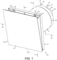
- the wall vent comprises a body 3 which is located within an opening in a building, such as through a wall.
- the body 3 comprises a duct 5 which extends through the opening in the building and includes an inlet 7 which is fluidly connected to a first, environmental space, here the external atmosphere from which a supply of fresh air is drawn, and an outlet 9 which is fluidly connected to a second space, here a space internal to the building.
- the duct 5 comprises a tubular element and includes a detent 10 at the inlet 7, which engages a counterpart detent 63 on a wind stop 51, as will be described in more detail hereinbelow.
- the body 3 further comprises an attachment member 11, here at the outlet 9, which allows for attachment of the body 3 to the building and receives a support member 17 of a cover panel assembly 15, as will be described in more detail hereinbelow.
- the attachment member 11 comprises a flange, here of rectangular shape, which extends about the periphery of the outlet 9 of the duct 5.
- the body 3 further comprises a collar 12 which is located about the periphery of the inlet 7 of the duct 5 and defines an inwardly-directed flange 14 which provides a stop for a wind stop 51, as will be described in more detail hereinbelow.
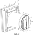
- the wall vent further comprises a cover panel assembly 15 which is fluidly connected to the outlet 9 of the duct 5, in this embodiment being attached to the attachment member 11 of the body 3.
- the cover panel assembly 15 comprises a support member 17 which is attached to the attachment member 11 of the body 3, here clipped thereto, a cover panel 19 which is coupled to the support member 17, and a linkage 21 which hingeably connects the cover panel 19 to the support member 17.
- the support member 17 includes first and second pivot couplings 23, here at an upper section thereof, and the cover panel 19 includes counterpart first and second pivot couplings 25, here at an upper section thereof, and the linkage 21 pivotably couples the respective ones of the pivot couplings 23, 25.
- the linkage 21 comprises first and second arms 27 which are pivotally coupled to respective ones of the pivot couplings 23, 25, and an interconnecting member 31 which interconnects the arms 27, whereby the arms 27 move in unison.
- the cover panel 19 can be moved between a closed position, in which cover panel 19 is juxtaposed the support member 17 and the outlet 9 of the duct 5 is closed, and various open positions, in which the cover panel 19 is open to different extents, as illustrated in Figures 7 and 8 .
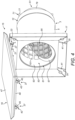
- the cover panel 19 can be raised clear of the support member 17 and allow unimpeded access to the duct 5, which enables removal of the wind stop 51 and a filter 81, as illustrated in Figures 4 and 5 .
- the support member 17 includes first and second engagement elements 35, here at a lower section thereof
- the cover panel 19 includes counterpart first and second engagement elements 37, here at a lower section thereof, which interengage with the engagement elements 35 of the support member 17, and enable the cover panel 19 to be fixed in the closed position or one of the plurality of set open positions.
- the engagement elements 35 of the support member 17 each comprise a lug 41 and the engagement elements 37 of the cover panel 19 each comprise a toothed section 43 having a plurality of teeth 45 which selectively engage the lug 41 of the counterpart engagement element 35 of the support member 17, and thereby enable the position of the cover panel 19 to be set in one of the plurality of positions.
- the cover panel 19 comprises an outer panel element 47 and an inner insulation element 49 which opposes the outlet 9 of the duct 5.
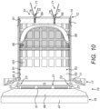
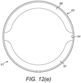
- the wall vent further comprises a wind stop 51 which is disposed at the inlet 7 of the duct 5 and acts to regulate the flow rate of the incoming air in the event of winds and wind gusts.
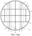
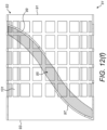
- the wind stop 51 comprises a body member 53 which includes a plurality of apertures 55 through which an air flow is drawn, and a plurality of flow regulators 57, which act to regulate the flow rate of the incoming air in the event of winds and wind gusts.
- the apertures 55 are arranged in a rectangular, grid pattern, but could have other forms.
- the body member 53 comprises an annular element 61 which has an outer diameter corresponding to the internal diameter of the duct 5, and the annular element 61 is seated at the flange 14 of the collar 12.
- the annular element 61 includes a detent 63 which engages the detent 10 on the duct 5 in order to provide that the wind stop 51 is oriented with a desired orientation.
- the body member 53 further comprises a plurality of supports 67 which support the respective ones of the flow regulators 57.
- the supports 67 each include an elongate channel 69 which receives the respective flow regulator 57.
- the flow regulators 57 each comprise at least one flexible element 71 which, in the absence of any wind or wind gust, adopts a configuration in a direction away from the apertures 55 in the body member 53, and, in the event of a wind or wind gust, flexes towards the apertures 55 in the body member 53 so as to restrict the flow path to the apertures 55, and thereby reduce the flow through the duct 5.
- the flexible element 71 could be pre-shaped such as to include a spine which is configured to fit within the channel 69 and with the flap sections 77, 79 inclined thereto.
- the flexible elements 71 of the flow regulators 57 are configured such as substantially to close the apertures 55 in the body member 53 when in the fully-flexed configuration.
- the flow regulators 57 each comprise a single flexible flap element 71 which is fixed in the channel 69 of the respective support 67 by an elongate engagement element 75 which is located in the channel 69, with the flap element 71 providing first and second flap sections 77, 79 to opposite sides of the support 67.
- the engagement element 75 has a shaped head 76, here having a taper, which determines the angle of the flap sections 77, 79 in relation to the longitudinal axis of the duct 5 in the absence of any wind or wind gust.
- first and second flap sections 77, 79 have a different shape and size, thereby providing for different response characteristics in response to winds or wind gusts.
- first and second flap sections 77, 79 are formed from a common sheet material, here of a silicone rubber.
- the flap sections 77, 79 are formed from a sheet having a thickness of from about 0.2 mm to about 1.0 mm, optionally from about 0.25 mm to about 0.6 mm, optionally from about 0.3 mm to about 0.5 mm.
- first and second flap sections 77, 79 could be formed differently, such as from sheet materials of different thickness, in order to provide for different response characteristics in response to winds or wind gusts.
- the flap sections 77, 79 of the flap elements 71 of the first and second flow regulators 57 could be formed differently, such as from sheet materials of different thickness, in order to provide for different response characteristics in response to winds or wind gusts.
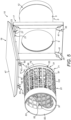
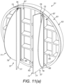
- the wall vent further comprises a filter 81 which acts to filter the incoming air and is disposed within the duct 5 downstream of the wind stop 51.
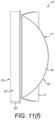
- the filter 81 comprises a tubular filter case 83 which defines an inner cavity 84, and a filter element 85 which is supported within the cavity 84 of the filter case 83.
- the filter case 83 has an outer diameter corresponding to the inner diameter of the duct 5.
- the filter case 83 has an inlet 91 which is fluidly connected to the wind stop 51 and an outlet 93 which is fluidly connected to the outlet 9 of the duct 5, such that the incoming air flow is directed through the cavity 84 of the filter case 83 and the filter element 85 which is supported therein.
- the filter case 83 includes a trap element 97 which is located within the cavity 84 thereof and extends over at least a lower section of the filter case 83, here at the outlet 93, such as to provide a dam or weir which prevents water, which is trapped by the filter element 85 and collects within the filter case 83, from passing forwardly out of the wall vent through the cover panel 19.
- the present inventors have recognized that, by arranging the filter element 85 to deliver any collected water to the a lower section of the filter case 83, and providing the trap element 97 to prevent the escape of this collected water, water can be prevented from passing forwardly out of the wall vent through the cover panel 19 and thereby enables the collected water to evaporate over time.
- the trap element 97 comprises a rearwardly and upwardly inclined flange, which acts to support a lower edge of the filter element 85.
- the filter case 83 further includes a support element 99 which is located within the cavity 84 thereof and extends over at least an upper section of the filter case 83, and acts to support the filter element 85.
- the support element 99 comprises a forwardly and downwardly inclined flange, which acts to support an upper edge of the filter element 85, whereby the filter element 85 is held in an inclined orient between the trap element 97 and the support element 99.
- the filter element 85 comprises a porous web having an average pore density of at most 20 pores per inch, optionally at most 15 pores per inch, here 10 pores per inch.
- the filter case 83 includes a plurality of apertures 101 in the peripheral wall thereof.
- the apertures 101 are arranged in a grid pattern.
- the filter case 83 has an open area of at least 50%. This construction allows for sound attenuation where the duct 5 is formed from a sound attenuating material, which acts to reduce noise created by the incoming air flow.
Landscapes
- Engineering & Computer Science (AREA)
- Chemical & Material Sciences (AREA)
- Combustion & Propulsion (AREA)
- Mechanical Engineering (AREA)
- General Engineering & Computer Science (AREA)
- Physics & Mathematics (AREA)
- Fluid Mechanics (AREA)
- Ventilation (AREA)
Claims (10)
- Wandlüfter mit einem Körper (3), der einen Kanal (5) bereitstellt, der einen Einlass (7) und einen Auslass (9) umfasst, und einer Abdeckplattenanordnung (15), die ein Trägerelement (17) und eine Abdeckplatte (19) umfasst, die den Auslass (9) des Kanals (5) abdeckt, dadurch gekennzeichnet, dass der Wandlüfter umfasst:
einen Verbindungsaufbau (21), der die Abdeckplatte (19) gelenkig mit dem Trägerelement (17) verbindet, worin der Verbindungsaufbau (21) so ausgestaltet ist, dass die Abdeckplatte (19) von dem Trägerelement (17) weggeschwenkt werden kann und Zugang zu dem Kanal (5) ermöglicht, worin das Trägerelement (17) mindestens eine Schwenkkupplung (23) aufweist, die Abdeckplatte (19) mindestens eine Gegenschwenkkupplung (25) aufweist und der Verbindungsaufbau (21) mindestens einen langgestreckten Arm (27) aufweist, der die Schwenkkupplungen (23, 25) schwenkbar koppelt. - Wandlüfter nach Anspruch 1, worin das Trägerelement (17) eine erste und eine zweite Schwenkkupplung (23) aufweist, die Abdeckplatte (19) eine erste und eine zweite Gegenschwenkkupplung (25) aufweist und der Verbindungsaufbau (21) einen ersten und einen zweiten langgestreckten Arm (27) aufweist, die schwenkbar mit den jeweiligen Schwenkkupplungen (23, 25) verbunden sind.
- Wandlüfter nach Anspruch 2, worin der Verbindungsaufbau (21) ferner ein Verbindungselement (31) umfasst, das die Arme (23, 25) miteinander verbindet, wodurch sich die Arme (23, 25) im Gleichklang bewegen.
- Wandlüfter nach einem der vorstehenden Ansprüche, worin der Verbindungsaufbau (21) es ermöglicht, die Abdeckplatte (19) zwischen einer geschlossenen Position, in der die Abdeckplatte (19) den Auslass (9) des Kanals (5) im Wesentlichen verschließt, und mehreren offenen Positionen zu bewegen, in denen die Abdeckplatte (19) zu mehreren unterschiedlichen Ausmaßen geöffnet ist.
- Wandlüfter nach Anspruch 4, worin das Trägerelement (17) mindestens ein Eingriffselement (35) und die Abdeckplatte (19) mindestens ein Gegeneingriffselement (37) aufweist, das mit dem Eingriffselement (35) des Trägerelements (17) ineinandergreift und es ermöglicht, die Abdeckplatte (19) in der geschlossenen Position oder einer der mehreren offenen Positionen zu fixieren.
- Wandlüfter nach Anspruch 5, worin das Eingriffselement (35, 37) von entweder dem Trägerelement (17) oder der Abdeckplatte (19) eine Nase (41) umfasst und das Eingriffselement (35, 37) des anderen von der Abdeckplatte (19) oder dem Trägerelement (17) einen gezahnten Abschnitt (43) mit mehreren Zähnen (45) umfasst, die selektiv in die Nase (41) des Gegeneingriffselements (35, 37) des Trägerelements (17) oder der Abdeckplatte (19) eingreifen und dadurch ermöglichen, dass die Position der Abdeckplatte (19) in die geschlossene Position oder eine der mehreren offenen Positionen eingestellt werden kann.
- Wandlüfter nach Anspruch 6, worin das Trägerelement (17) ein erstes und ein zweites Eingriffselement (35) aufweist und die Abdeckplatte (19) ein entsprechendes erstes und zweites Eingriffselement (37) aufweist, die mit den Eingriffselementen (35) des Trägerelements (17) ineinandergreifen.
- Wandlüfter nach einem der vorstehenden Ansprüche, welcher ferner einen Windstopper (51) aufweist, der am Einlass (7) des Kanals (5) angeordnet ist.
- Wandlüfter nach Anspruch 8, welcher ferner einen Filter (81) aufweist, der innerhalb des Kanals (5) stromabwärts des Windstoppers (51) angeordnet ist.
- Wandlüfter nach Anspruch 9, worin der Windstopper (51) und der Filter (81) in Kombination gleitend in dem Kanal (5) angeordnet und aus diesem herausnehmbar sind.
Priority Applications (2)
| Application Number | Priority Date | Filing Date | Title |
|---|---|---|---|
| EP15158008.1A EP3064844B1 (de) | 2015-03-06 | 2015-03-06 | Ventilator |
| PCT/EP2016/054812 WO2016142346A1 (en) | 2015-03-06 | 2016-03-07 | Ventilation apparatus |
Applications Claiming Priority (1)
| Application Number | Priority Date | Filing Date | Title |
|---|---|---|---|
| EP15158008.1A EP3064844B1 (de) | 2015-03-06 | 2015-03-06 | Ventilator |
Publications (3)
| Publication Number | Publication Date |
|---|---|
| EP3064844A1 EP3064844A1 (de) | 2016-09-07 |
| EP3064844C0 EP3064844C0 (de) | 2024-11-06 |
| EP3064844B1 true EP3064844B1 (de) | 2024-11-06 |
Family
ID=52629438
Family Applications (1)
| Application Number | Title | Priority Date | Filing Date |
|---|---|---|---|
| EP15158008.1A Active EP3064844B1 (de) | 2015-03-06 | 2015-03-06 | Ventilator |
Country Status (2)
| Country | Link |
|---|---|
| EP (1) | EP3064844B1 (de) |
| WO (1) | WO2016142346A1 (de) |
Families Citing this family (3)
| Publication number | Priority date | Publication date | Assignee | Title |
|---|---|---|---|---|
| CN113141746B (zh) * | 2021-03-30 | 2022-09-23 | 联想(北京)有限公司 | 一种电子设备 |
| CN113405190A (zh) * | 2021-05-28 | 2021-09-17 | 广州云山技术有限公司 | 一种噪音低的新风净化器 |
| CN113375227B (zh) * | 2021-07-14 | 2024-09-27 | 珠海格力电器股份有限公司 | 一种空调的出风控制装置、空调及其出风控制方法 |
Citations (5)
| Publication number | Priority date | Publication date | Assignee | Title |
|---|---|---|---|---|
| GB2311848A (en) * | 1996-04-04 | 1997-10-08 | Titon Hardware | Slot ventilator |
| EP0971091A2 (de) * | 1998-07-09 | 2000-01-12 | Andreas Grasl | Gelenkanordnung zur Betätigung einer Klappe oder dergleichen |
| WO2002093084A1 (en) * | 2001-05-16 | 2002-11-21 | Titon Hardware Limited | Ventilation assemblies |
| WO2011113213A1 (en) * | 2010-03-19 | 2011-09-22 | Zhijun Dong | Ventilation system for window or door |
| EP2383401A2 (de) * | 2010-04-27 | 2011-11-02 | Glazing Vision Limited | Entlüftungsanordnung |
Family Cites Families (4)
| Publication number | Priority date | Publication date | Assignee | Title |
|---|---|---|---|---|
| US3171343A (en) * | 1962-10-19 | 1965-03-02 | Acme Mfg Company | Means for discharging or exhausting air from the interior of a building |
| US4237621A (en) * | 1979-05-18 | 1980-12-09 | Lucien Boismenu | Damper structure for a clothes dryer vent |
| US20050202778A1 (en) * | 2004-03-11 | 2005-09-15 | Stravitz David M. | Wall-mounted exhaust vents |
| US20090280737A1 (en) * | 2008-05-06 | 2009-11-12 | Corey Scott Jacak | Exhaust vent arrangement and method of operating the same |
-
2015
- 2015-03-06 EP EP15158008.1A patent/EP3064844B1/de active Active
-
2016
- 2016-03-07 WO PCT/EP2016/054812 patent/WO2016142346A1/en not_active Ceased
Patent Citations (5)
| Publication number | Priority date | Publication date | Assignee | Title |
|---|---|---|---|---|
| GB2311848A (en) * | 1996-04-04 | 1997-10-08 | Titon Hardware | Slot ventilator |
| EP0971091A2 (de) * | 1998-07-09 | 2000-01-12 | Andreas Grasl | Gelenkanordnung zur Betätigung einer Klappe oder dergleichen |
| WO2002093084A1 (en) * | 2001-05-16 | 2002-11-21 | Titon Hardware Limited | Ventilation assemblies |
| WO2011113213A1 (en) * | 2010-03-19 | 2011-09-22 | Zhijun Dong | Ventilation system for window or door |
| EP2383401A2 (de) * | 2010-04-27 | 2011-11-02 | Glazing Vision Limited | Entlüftungsanordnung |
Also Published As
| Publication number | Publication date |
|---|---|
| WO2016142346A1 (en) | 2016-09-15 |
| EP3064844C0 (de) | 2024-11-06 |
| EP3064844A1 (de) | 2016-09-07 |
Similar Documents
| Publication | Publication Date | Title |
|---|---|---|
| WO2015191029A1 (en) | Shrouded roof vent for a vehicle | |
| EP3064844B1 (de) | Ventilator | |
| US5487247A (en) | Ventilated roof and wall structure | |
| US20120149293A1 (en) | Extraction Fan Assembly for an Animal Husbandry Barn | |
| JP3217822U (ja) | 蜜蜂巣箱用換気断熱箱 | |
| NZ592556A (en) | Improvements in or relating to animal shelter structures | |
| EP2574860A2 (de) | Ventilatie-inrichting met verwarming, alsmede gebouw met een dergelijke ventilatie-inrichting | |
| US4567816A (en) | Unidirectional vent | |
| US20170122609A1 (en) | Flapper valve adaptor for a roof vent and method of installing the same | |
| EP2264376B1 (de) | Luftventilator mit Filter und Rückschlagklappe zur Leitung von Austauschluft in einen Raum | |
| CN213901359U (zh) | 一种节能建筑通风设备 | |
| EP1689953A1 (de) | Kippfenster | |
| GB2155170A (en) | Adjustable ventilators | |
| US20080034482A1 (en) | Ventilated toilet | |
| DE10247102A1 (de) | Luftabzug mit sich schrägstellender Haube | |
| US6206774B1 (en) | Roof environmental exhaust duct | |
| AU2010100676A4 (en) | Improved louvre vent assembly and blade therefor | |
| US20150105012A1 (en) | Vent cover | |
| US3385195A (en) | Air inlet for animal houses and the like | |
| CA2869492C (en) | Flapper valve adaptor for a roof vent and method of installing the same | |
| KR20090116273A (ko) | 필터가 구비된 자연 환기구 | |
| JPS6112503Y2 (de) | ||
| JP4409051B2 (ja) | 壁用換気装置 | |
| GB2383124A (en) | An air pressure operated ventilator device | |
| CN213678328U (zh) | 一种户外可防虫防鼠的垃圾箱 |
Legal Events
| Date | Code | Title | Description |
|---|---|---|---|
| PUAI | Public reference made under article 153(3) epc to a published international application that has entered the european phase |
Free format text: ORIGINAL CODE: 0009012 |
|
| AK | Designated contracting states |
Kind code of ref document: A1 Designated state(s): AL AT BE BG CH CY CZ DE DK EE ES FI FR GB GR HR HU IE IS IT LI LT LU LV MC MK MT NL NO PL PT RO RS SE SI SK SM TR |
|
| AX | Request for extension of the european patent |
Extension state: BA ME |
|
| STAA | Information on the status of an ep patent application or granted ep patent |
Free format text: STATUS: REQUEST FOR EXAMINATION WAS MADE |
|
| 17P | Request for examination filed |
Effective date: 20170307 |
|
| RBV | Designated contracting states (corrected) |
Designated state(s): AL AT BE BG CH CY CZ DE DK EE ES FI FR GB GR HR HU IE IS IT LI LT LU LV MC MK MT NL NO PL PT RO RS SE SI SK SM TR |
|
| STAA | Information on the status of an ep patent application or granted ep patent |
Free format text: STATUS: EXAMINATION IS IN PROGRESS |
|
| 17Q | First examination report despatched |
Effective date: 20190809 |
|
| REG | Reference to a national code |
Free format text: PREVIOUS MAIN CLASS: F24F0007000000 Ref country code: DE Ref legal event code: R079 Ref document number: 602015090311 Country of ref document: DE Free format text: PREVIOUS MAIN CLASS: F24F0007000000 Ipc: F24F0007003000 |
|
| GRAP | Despatch of communication of intention to grant a patent |
Free format text: ORIGINAL CODE: EPIDOSNIGR1 |
|
| STAA | Information on the status of an ep patent application or granted ep patent |
Free format text: STATUS: GRANT OF PATENT IS INTENDED |
|
| RIC1 | Information provided on ipc code assigned before grant |
Ipc: F24F 11/74 20180101ALI20240730BHEP Ipc: F24F 13/08 20060101ALI20240730BHEP Ipc: F24F 7/003 20210101AFI20240730BHEP |
|
| INTG | Intention to grant announced |
Effective date: 20240807 |
|
| GRAS | Grant fee paid |
Free format text: ORIGINAL CODE: EPIDOSNIGR3 |
|
| GRAA | (expected) grant |
Free format text: ORIGINAL CODE: 0009210 |
|
| STAA | Information on the status of an ep patent application or granted ep patent |
Free format text: STATUS: THE PATENT HAS BEEN GRANTED |
|
| AK | Designated contracting states |
Kind code of ref document: B1 Designated state(s): AL AT BE BG CH CY CZ DE DK EE ES FI FR GB GR HR HU IE IS IT LI LT LU LV MC MK MT NL NO PL PT RO RS SE SI SK SM TR |
|
| REG | Reference to a national code |
Ref country code: GB Ref legal event code: FG4D |
|
| REG | Reference to a national code |
Ref country code: CH Ref legal event code: EP |
|
| REG | Reference to a national code |
Ref country code: DE Ref legal event code: R096 Ref document number: 602015090311 Country of ref document: DE |
|
| REG | Reference to a national code |
Ref country code: IE Ref legal event code: FG4D |
|
| U01 | Request for unitary effect filed |
Effective date: 20241129 |
|
| U07 | Unitary effect registered |
Designated state(s): AT BE BG DE DK EE FI FR IT LT LU LV MT NL PT RO SE SI Effective date: 20241210 |
|
| U20 | Renewal fee for the european patent with unitary effect paid |
Year of fee payment: 11 Effective date: 20250129 |
|
| PG25 | Lapsed in a contracting state [announced via postgrant information from national office to epo] |
Ref country code: IS Free format text: LAPSE BECAUSE OF FAILURE TO SUBMIT A TRANSLATION OF THE DESCRIPTION OR TO PAY THE FEE WITHIN THE PRESCRIBED TIME-LIMIT Effective date: 20250306 Ref country code: HR Free format text: LAPSE BECAUSE OF FAILURE TO SUBMIT A TRANSLATION OF THE DESCRIPTION OR TO PAY THE FEE WITHIN THE PRESCRIBED TIME-LIMIT Effective date: 20241106 |
|
| PG25 | Lapsed in a contracting state [announced via postgrant information from national office to epo] |
Ref country code: ES Free format text: LAPSE BECAUSE OF FAILURE TO SUBMIT A TRANSLATION OF THE DESCRIPTION OR TO PAY THE FEE WITHIN THE PRESCRIBED TIME-LIMIT Effective date: 20241106 |
|
| PGFP | Annual fee paid to national office [announced via postgrant information from national office to epo] |
Ref country code: NO Payment date: 20250130 Year of fee payment: 11 |
|
| PG25 | Lapsed in a contracting state [announced via postgrant information from national office to epo] |
Ref country code: GR Free format text: LAPSE BECAUSE OF FAILURE TO SUBMIT A TRANSLATION OF THE DESCRIPTION OR TO PAY THE FEE WITHIN THE PRESCRIBED TIME-LIMIT Effective date: 20250207 |
|
| PG25 | Lapsed in a contracting state [announced via postgrant information from national office to epo] |
Ref country code: PL Free format text: LAPSE BECAUSE OF FAILURE TO SUBMIT A TRANSLATION OF THE DESCRIPTION OR TO PAY THE FEE WITHIN THE PRESCRIBED TIME-LIMIT Effective date: 20241106 |
|
| PGFP | Annual fee paid to national office [announced via postgrant information from national office to epo] |
Ref country code: GB Payment date: 20250129 Year of fee payment: 11 |
|
| PG25 | Lapsed in a contracting state [announced via postgrant information from national office to epo] |
Ref country code: RS Free format text: LAPSE BECAUSE OF FAILURE TO SUBMIT A TRANSLATION OF THE DESCRIPTION OR TO PAY THE FEE WITHIN THE PRESCRIBED TIME-LIMIT Effective date: 20250206 |
|
| PG25 | Lapsed in a contracting state [announced via postgrant information from national office to epo] |
Ref country code: SM Free format text: LAPSE BECAUSE OF FAILURE TO SUBMIT A TRANSLATION OF THE DESCRIPTION OR TO PAY THE FEE WITHIN THE PRESCRIBED TIME-LIMIT Effective date: 20241106 |
|
| PG25 | Lapsed in a contracting state [announced via postgrant information from national office to epo] |
Ref country code: SK Free format text: LAPSE BECAUSE OF FAILURE TO SUBMIT A TRANSLATION OF THE DESCRIPTION OR TO PAY THE FEE WITHIN THE PRESCRIBED TIME-LIMIT Effective date: 20241106 |
|
| PG25 | Lapsed in a contracting state [announced via postgrant information from national office to epo] |
Ref country code: CZ Free format text: LAPSE BECAUSE OF FAILURE TO SUBMIT A TRANSLATION OF THE DESCRIPTION OR TO PAY THE FEE WITHIN THE PRESCRIBED TIME-LIMIT Effective date: 20241106 |
|
| PLBE | No opposition filed within time limit |
Free format text: ORIGINAL CODE: 0009261 |
|
| STAA | Information on the status of an ep patent application or granted ep patent |
Free format text: STATUS: NO OPPOSITION FILED WITHIN TIME LIMIT |
|
| PG25 | Lapsed in a contracting state [announced via postgrant information from national office to epo] |
Ref country code: MC Free format text: LAPSE BECAUSE OF FAILURE TO SUBMIT A TRANSLATION OF THE DESCRIPTION OR TO PAY THE FEE WITHIN THE PRESCRIBED TIME-LIMIT Effective date: 20241106 |
|
| 26N | No opposition filed |
Effective date: 20250807 |
|
| REG | Reference to a national code |
Ref country code: CH Ref legal event code: H13 Free format text: ST27 STATUS EVENT CODE: U-0-0-H10-H13 (AS PROVIDED BY THE NATIONAL OFFICE) Effective date: 20251024 |
|
| PG25 | Lapsed in a contracting state [announced via postgrant information from national office to epo] |
Ref country code: CH Free format text: LAPSE BECAUSE OF NON-PAYMENT OF DUE FEES Effective date: 20250331 |
|
| PG25 | Lapsed in a contracting state [announced via postgrant information from national office to epo] |
Ref country code: IE Free format text: LAPSE BECAUSE OF NON-PAYMENT OF DUE FEES Effective date: 20250306 |