EP3064733A1 - Engine cooling system - Google Patents
Engine cooling system Download PDFInfo
- Publication number
- EP3064733A1 EP3064733A1 EP14856996.5A EP14856996A EP3064733A1 EP 3064733 A1 EP3064733 A1 EP 3064733A1 EP 14856996 A EP14856996 A EP 14856996A EP 3064733 A1 EP3064733 A1 EP 3064733A1
- Authority
- EP
- European Patent Office
- Prior art keywords
- radiator
- cooling
- cooling water
- engine
- condenser
- Prior art date
- Legal status (The legal status is an assumption and is not a legal conclusion. Google has not performed a legal analysis and makes no representation as to the accuracy of the status listed.)
- Granted
Links
Images
Classifications
-
- F—MECHANICAL ENGINEERING; LIGHTING; HEATING; WEAPONS; BLASTING
- F01—MACHINES OR ENGINES IN GENERAL; ENGINE PLANTS IN GENERAL; STEAM ENGINES
- F01P—COOLING OF MACHINES OR ENGINES IN GENERAL; COOLING OF INTERNAL-COMBUSTION ENGINES
- F01P3/00—Liquid cooling
- F01P3/22—Liquid cooling characterised by evaporation and condensation of coolant in closed cycles; characterised by the coolant reaching higher temperatures than normal atmospheric boiling-point
- F01P3/2285—Closed cycles with condenser and feed pump
-
- F—MECHANICAL ENGINEERING; LIGHTING; HEATING; WEAPONS; BLASTING
- F01—MACHINES OR ENGINES IN GENERAL; ENGINE PLANTS IN GENERAL; STEAM ENGINES
- F01K—STEAM ENGINE PLANTS; STEAM ACCUMULATORS; ENGINE PLANTS NOT OTHERWISE PROVIDED FOR; ENGINES USING SPECIAL WORKING FLUIDS OR CYCLES
- F01K5/00—Plants characterised by use of means for storing steam in an alkali to increase steam pressure, e.g. of Honigmann or Koenemann type
- F01K5/02—Plants characterised by use of means for storing steam in an alkali to increase steam pressure, e.g. of Honigmann or Koenemann type used in regenerative installation
-
- F—MECHANICAL ENGINEERING; LIGHTING; HEATING; WEAPONS; BLASTING
- F01—MACHINES OR ENGINES IN GENERAL; ENGINE PLANTS IN GENERAL; STEAM ENGINES
- F01K—STEAM ENGINE PLANTS; STEAM ACCUMULATORS; ENGINE PLANTS NOT OTHERWISE PROVIDED FOR; ENGINES USING SPECIAL WORKING FLUIDS OR CYCLES
- F01K9/00—Plants characterised by condensers arranged or modified to co-operate with the engines
- F01K9/003—Plants characterised by condensers arranged or modified to co-operate with the engines condenser cooling circuits
-
- F—MECHANICAL ENGINEERING; LIGHTING; HEATING; WEAPONS; BLASTING
- F01—MACHINES OR ENGINES IN GENERAL; ENGINE PLANTS IN GENERAL; STEAM ENGINES
- F01P—COOLING OF MACHINES OR ENGINES IN GENERAL; COOLING OF INTERNAL-COMBUSTION ENGINES
- F01P3/00—Liquid cooling
- F01P3/12—Arrangements for cooling other engine or machine parts
-
- F—MECHANICAL ENGINEERING; LIGHTING; HEATING; WEAPONS; BLASTING
- F01—MACHINES OR ENGINES IN GENERAL; ENGINE PLANTS IN GENERAL; STEAM ENGINES
- F01P—COOLING OF MACHINES OR ENGINES IN GENERAL; COOLING OF INTERNAL-COMBUSTION ENGINES
- F01P7/00—Controlling of coolant flow
- F01P7/14—Controlling of coolant flow the coolant being liquid
- F01P7/16—Controlling of coolant flow the coolant being liquid by thermostatic control
- F01P7/165—Controlling of coolant flow the coolant being liquid by thermostatic control characterised by systems with two or more loops
-
- F—MECHANICAL ENGINEERING; LIGHTING; HEATING; WEAPONS; BLASTING
- F01—MACHINES OR ENGINES IN GENERAL; ENGINE PLANTS IN GENERAL; STEAM ENGINES
- F01P—COOLING OF MACHINES OR ENGINES IN GENERAL; COOLING OF INTERNAL-COMBUSTION ENGINES
- F01P9/00—Cooling having pertinent characteristics not provided for in, or of interest apart from, groups F01P1/00 - F01P7/00
- F01P9/02—Cooling by evaporation, e.g. by spraying water on to cylinders
-
- F—MECHANICAL ENGINEERING; LIGHTING; HEATING; WEAPONS; BLASTING
- F02—COMBUSTION ENGINES; HOT-GAS OR COMBUSTION-PRODUCT ENGINE PLANTS
- F02G—HOT GAS OR COMBUSTION-PRODUCT POSITIVE-DISPLACEMENT ENGINE PLANTS; USE OF WASTE HEAT OF COMBUSTION ENGINES; NOT OTHERWISE PROVIDED FOR
- F02G5/00—Profiting from waste heat of combustion engines, not otherwise provided for
- F02G5/02—Profiting from waste heat of exhaust gases
- F02G5/04—Profiting from waste heat of exhaust gases in combination with other waste heat from combustion engines
-
- F—MECHANICAL ENGINEERING; LIGHTING; HEATING; WEAPONS; BLASTING
- F01—MACHINES OR ENGINES IN GENERAL; ENGINE PLANTS IN GENERAL; STEAM ENGINES
- F01P—COOLING OF MACHINES OR ENGINES IN GENERAL; COOLING OF INTERNAL-COMBUSTION ENGINES
- F01P2060/00—Cooling circuits using auxiliaries
- F01P2060/02—Intercooler
-
- F—MECHANICAL ENGINEERING; LIGHTING; HEATING; WEAPONS; BLASTING
- F01—MACHINES OR ENGINES IN GENERAL; ENGINE PLANTS IN GENERAL; STEAM ENGINES
- F01P—COOLING OF MACHINES OR ENGINES IN GENERAL; COOLING OF INTERNAL-COMBUSTION ENGINES
- F01P2060/00—Cooling circuits using auxiliaries
- F01P2060/16—Outlet manifold
-
- F—MECHANICAL ENGINEERING; LIGHTING; HEATING; WEAPONS; BLASTING
- F02—COMBUSTION ENGINES; HOT-GAS OR COMBUSTION-PRODUCT ENGINE PLANTS
- F02G—HOT GAS OR COMBUSTION-PRODUCT POSITIVE-DISPLACEMENT ENGINE PLANTS; USE OF WASTE HEAT OF COMBUSTION ENGINES; NOT OTHERWISE PROVIDED FOR
- F02G2260/00—Recuperating heat from exhaust gases of combustion engines and heat from cooling circuits
-
- Y—GENERAL TAGGING OF NEW TECHNOLOGICAL DEVELOPMENTS; GENERAL TAGGING OF CROSS-SECTIONAL TECHNOLOGIES SPANNING OVER SEVERAL SECTIONS OF THE IPC; TECHNICAL SUBJECTS COVERED BY FORMER USPC CROSS-REFERENCE ART COLLECTIONS [XRACs] AND DIGESTS
- Y02—TECHNOLOGIES OR APPLICATIONS FOR MITIGATION OR ADAPTATION AGAINST CLIMATE CHANGE
- Y02T—CLIMATE CHANGE MITIGATION TECHNOLOGIES RELATED TO TRANSPORTATION
- Y02T10/00—Road transport of goods or passengers
- Y02T10/10—Internal combustion engine [ICE] based vehicles
- Y02T10/12—Improving ICE efficiencies
Definitions
- the present invention relates to an engine cooling system, and more specifically relates to an engine cooling system including a Rankine cycle with an improved performance while suppressing an increase in vehicle weight caused by employing the Rankine cycle.
- Patent Literature 1 engine-main-body cooling water heated by an engine main body is used as a heating source of a Rankine cycle while intercooler cooling water cooled by a sub-radiator is used as a cooling source, so that a temperature difference between these flows of cooling water can be recovered as a power in a compressor (turbine).
- the above-described engine-main-body cooling water and intercooler cooling water are air-cooled respectively in a radiator and a sub-radiator, which are disposed at a front surface of a vehicle.
- a condenser for an air conditioner is disposed in front of the radiator and the sub-radiator, the condenser blocks vehicle-speed wind from flowing through the vehicle.
- the Rankine cycle may not be provided with cooling water having a sufficient temperature difference.
- Patent Document 1 Japanese patent application Kokai publication No. 11-51582
- An object of the present invention is to provide an engine cooling system capable of suppressing an increase in vehicle weight caused by employing a Rankine cycle and capable of improving the Rankine cycle performance.
- an engine cooling system of the present invention is an engine cooling system including: a Rankine cycle configured such that a first coolant circulates through a cooling pump, an evaporator, an expander, and a condenser in this order; a cooling cycle for an air conditioner configured to cool a vehicle by utilizing a vaporization of a liquid second coolant; a radiator which is disposed at a front surface of the vehicle, and through which engine-main-body cooling water flows; and a sub-radiator through which intercooler cooling water flows.
- the engine cooling system uses some of inlet-side cooling water of the radiator as a heating source for the evaporator, and some of outlet-side cooling water of the sub-radiator as a cooling source for the condenser.
- the engine cooling system is characterized in that the vaporized second coolant is cooled and again liquefied by using some of the outlet-side cooling water of the sub-radiator in the condenser.
- a vaporized coolant in the cooling cycle for the air conditioner is liquefied not by an air-cooled condenser disposed at a front surface of a vehicle, but by utilizing some of the outlet-side cooling water of the sub-radiator in the evaporator of the Rankine cycle.
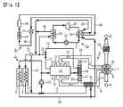
- Fig. 1 is a configuration diagram of an engine cooling system according to an embodiment of the present invention.
- FIG. 1 shows an engine cooling system according to the embodiment of the present invention.
- This engine cooling system includes a sub-radiator 2 and a radiator 3 disposed in this order from a front surface of a vehicle 1.
- the sub-radiator 2 and the radiator 3 are configured to perform air-cooling by utilizing vehicle-speed wind and cooling wind of a cooling fan (not shown) when the vehicle 1 is running or idling.
- air A is drawn to an intake passage 5, and passes as drawn air 6 through an air cleaner not shown.
- the drawn air 6 is compressed by a compressor 8 of a turbocharger 7. After cooled by a water-cooled intercooler 9, the drawn air 6 is supplied to an engine main body 11 via an intake manifold 10.
- Intercooler cooling water 12 used for cooling with the intercooler 9 is forced to circulate between the intercooler 9 and the sub-radiator 2 by a water pump 13.
- the drawn air 6 supplied to the engine main body 11 is mixed with a fuel and burned, thereby generating a thermal energy. Then, a burned gas 14 thus obtained is discharged from an exhaust manifold 15 to an exhaust passage 16. Some of the burned gas 14 is diverted as an EGR gas 18 into an EGR passage 17, which is located on a downstream side of the intercooler 9 and connected to the intake passage 5. To the EGR passage 17, a water-cooled EGR cooler 19 and an EGR valve 20 configured to adjust a flow amount of the EGR gas 18 are disposed in this order from the exhaust passage 16 side.
- Flow amounts of engine-main-body cooling water 21 for cooling the engine main body 11 and EGR-cooler cooling water 22 used for cooling in the EGR cooler 19 are regulated by a thermostat 23.
- the engine-main-body cooling water 21 and the EGR-cooler cooling water 22 are forced to circulate between the radiator 3 and corresponding one of the engine main body 11 and the EGR cooler 19 by the water pump 13.
- cooling water 24 diverted from the thermostat 23 during warming-up time of the engine main body 11 circulates without passing through the radiator 3. Note that some of the engine-main-body cooling water 21 normally flows as the EGR-cooler cooling water 22.
- a portion of the burned gas 14 which is not diverted to the EGR passage 17 is released as an exhaust gas G into the atmosphere after an exhaust gas purification device 26 including DPF, SCR, and the like purifies harmful substances by driving the rotation of a turbine 25 of the turbocharger 7.
- this engine cooling system is provided with a Rankine cycle 32 in parallel to the conventional engine cooling system including the sub-radiator 2 and the radiator 3.
- the Rankine cycle 32 is configured such that a first coolant 31 circulates through a cooling pump 27, a first evaporator 28, a first expander 29, and a first condenser 30 in this order.
- inlet-side cooling water 33 of the radiator 3 (the engine-main-body cooling water 21 and the EGR-cooler cooling water 22 after heating) flows by by-passing an upstream side of the thermostat 23.
- outlet-side cooling water 34 of the sub-radiator 2 (the intercooler cooling water 12 after air-cooling) is diverted from the vicinity of an inlet of the intercooler 9.
- the outlet-side cooling water 34 as cooling water 35 merges with cooling water 36 which has passed through the first evaporator 28.
- the coolant 31 which flows through the Rankine cycle 32 is compressed in a liquid state in the cooling pump 27, and heated at a constant pressure by some of the inlet-side cooling water 33 of the radiator 3 in the first evaporator 28, so that the coolant 31 is turned into an over-heated vapor at high pressure. After an adiabatic expansion in the first expander 29, the coolant 31 is cooled at a constant pressure by some of the outlet-side cooling water 34 of the sub-radiator 2 in the first condenser 30, and returned to a liquid again.
- the engine cooling system as described above includes a cooling cycle 41 for an air conditioner.
- the cooling cycle 41 is configured that that a second coolant 40 circulates through a second expander 37, a second evaporator 38, a compressor 39, and a side to be cooled of the first condenser 30 in the Rankine cycle 32 in this order.
- the second coolant 40 in a gas state is compressed into a semi-liquid state at high temperature and high pressure by the compressor 39.
- the second coolant 40 is cooled and further liquefied by some of the outlet-side cooling water 34 of the sub-radiator 2 in the first condenser 30, so that the second coolant 40 is turned into a liquid in a mist form at low pressure and low temperature by the second expander 37.
- the second coolant 40 is vaporized again through heat exchange with air in the second evaporator 38 to generate cooling wind, thereby cooling the vehicle 1.
- the second coolant 40 of the cooling cycle 41 for the air conditioner is liquefied not by an air-cooled condenser for the air conditioner disposed at the front surface of the vehicle 1 but by utilizing some of the outlet-side cooling water 34 air-cooled by the sub-radiator 2 in the first evaporator 30 of the Rankine cycle 32.
- the cooling target of the engine cooling system of the present invention is not limited to the diesel engine 4 as described above, and includes a gasoline engine, as well.
Landscapes
- Engineering & Computer Science (AREA)
- Chemical & Material Sciences (AREA)
- Combustion & Propulsion (AREA)
- Mechanical Engineering (AREA)
- General Engineering & Computer Science (AREA)
- Physics & Mathematics (AREA)
- Thermal Sciences (AREA)
- Engine Equipment That Uses Special Cycles (AREA)
Abstract
Description
- The present invention relates to an engine cooling system, and more specifically relates to an engine cooling system including a Rankine cycle with an improved performance while suppressing an increase in vehicle weight caused by employing the Rankine cycle.
- Conventionally, there has been a proposal to employ a Rankine cycle in a vehicle in order to recover waste heat from an engine and thereby improve the fuel economy, as described in, for example, Japanese patent application Kokai publication No.
11-51582 - However, when such a Rankine cycle is employed on a vehicle, the vehicle weight is increased. This may counterbalance the effect of improving the fuel economy.
- On the other hand, the above-described engine-main-body cooling water and intercooler cooling water are air-cooled respectively in a radiator and a sub-radiator, which are disposed at a front surface of a vehicle. However, since a condenser for an air conditioner is disposed in front of the radiator and the sub-radiator, the condenser blocks vehicle-speed wind from flowing through the vehicle. Hence, the Rankine cycle may not be provided with cooling water having a sufficient temperature difference.
- Patent Document 1: Japanese patent application Kokai publication No.
11-51582 - An object of the present invention is to provide an engine cooling system capable of suppressing an increase in vehicle weight caused by employing a Rankine cycle and capable of improving the Rankine cycle performance.
- In order to achieve the above object, an engine cooling system of the present invention is an engine cooling system including: a Rankine cycle configured such that a first coolant circulates through a cooling pump, an evaporator, an expander, and a condenser in this order; a cooling cycle for an air conditioner configured to cool a vehicle by utilizing a vaporization of a liquid second coolant; a radiator which is disposed at a front surface of the vehicle, and through which engine-main-body cooling water flows; and a sub-radiator through which intercooler cooling water flows. The engine cooling system uses some of inlet-side cooling water of the radiator as a heating source for the evaporator, and some of outlet-side cooling water of the sub-radiator as a cooling source for the condenser. The engine cooling system is characterized in that the vaporized second coolant is cooled and again liquefied by using some of the outlet-side cooling water of the sub-radiator in the condenser.
- According to the engine cooling system of the present invention, unlike a conventional case, a vaporized coolant in the cooling cycle for the air conditioner is liquefied not by an air-cooled condenser disposed at a front surface of a vehicle, but by utilizing some of the outlet-side cooling water of the sub-radiator in the evaporator of the Rankine cycle. This eliminates the need of providing a vehicle with such an air-cooled condenser, and makes it possible to configure the cooling cycle for the air conditioner of water-cooled type and to downsize the entire system. Hence, it is possible to suppress an increase in vehicle weight caused by employing the Rankine cycle.
- Moreover, since no air-cooled condenser for an air conditioner is present at the front surface of the vehicle, this reduces the air flow resistance for the sub-radiator and the radiator, and makes it possible to provide the Rankine cycle with cooling water having a sufficient temperature difference, and improve the performance of the Rankine cycle.
- [
Fig. 1] Fig. 1 is a configuration diagram of an engine cooling system according to an embodiment of the present invention. - Hereinafter an embodiment of the present invention will be described with reference to the drawing.
Fig. 1 shows an engine cooling system according to the embodiment of the present invention. - This engine cooling system includes a
sub-radiator 2 and aradiator 3 disposed in this order from a front surface of a vehicle 1. Thesub-radiator 2 and theradiator 3 are configured to perform air-cooling by utilizing vehicle-speed wind and cooling wind of a cooling fan (not shown) when the vehicle 1 is running or idling. - In a diesel engine 4, which is a cooling target of the engine cooling system, air A is drawn to an intake passage 5, and passes as drawn
air 6 through an air cleaner not shown. The drawnair 6 is compressed by acompressor 8 of a turbocharger 7. After cooled by a water-cooledintercooler 9, the drawnair 6 is supplied to an enginemain body 11 via anintake manifold 10. -
Intercooler cooling water 12 used for cooling with theintercooler 9 is forced to circulate between theintercooler 9 and thesub-radiator 2 by awater pump 13. - The drawn
air 6 supplied to the enginemain body 11 is mixed with a fuel and burned, thereby generating a thermal energy. Then, a burnedgas 14 thus obtained is discharged from anexhaust manifold 15 to anexhaust passage 16. Some of the burnedgas 14 is diverted as anEGR gas 18 into anEGR passage 17, which is located on a downstream side of theintercooler 9 and connected to the intake passage 5. To the EGRpassage 17, a water-cooledEGR cooler 19 and anEGR valve 20 configured to adjust a flow amount of theEGR gas 18 are disposed in this order from theexhaust passage 16 side. - Flow amounts of engine-main-
body cooling water 21 for cooling the enginemain body 11 and EGR-cooler cooling water 22 used for cooling in the EGRcooler 19 are regulated by athermostat 23. The engine-main-body cooling water 21 and the EGR-cooler cooling water 22 are forced to circulate between theradiator 3 and corresponding one of the enginemain body 11 and theEGR cooler 19 by thewater pump 13. - On the other hand, cooling
water 24 diverted from thethermostat 23 during warming-up time of the enginemain body 11 circulates without passing through theradiator 3. Note that some of the engine-main-body cooling water 21 normally flows as the EGR-cooler cooling water 22. - A portion of the burned
gas 14 which is not diverted to the EGRpassage 17 is released as an exhaust gas G into the atmosphere after an exhaustgas purification device 26 including DPF, SCR, and the like purifies harmful substances by driving the rotation of aturbine 25 of the turbocharger 7. - Further, this engine cooling system is provided with a Rankine
cycle 32 in parallel to the conventional engine cooling system including thesub-radiator 2 and theradiator 3. The Rankinecycle 32 is configured such that afirst coolant 31 circulates through acooling pump 27, afirst evaporator 28, afirst expander 29, and afirst condenser 30 in this order. - To a heating side of the
first evaporator 28 in this Rankinecycle 32, some of inlet-side cooling water 33 of the radiator 3 (the engine-main-body cooling water 21 and the EGR-cooler cooling water 22 after heating) flows by by-passing an upstream side of thethermostat 23. - Moreover, to a cooling side of the
first condenser 30, some of outlet-side cooling water 34 of the sub-radiator 2 (theintercooler cooling water 12 after air-cooling) is diverted from the vicinity of an inlet of theintercooler 9. After passing through thefirst condenser 30, the outlet-side cooling water 34 as coolingwater 35 merges withcooling water 36 which has passed through thefirst evaporator 28. - The
coolant 31 which flows through the Rankinecycle 32 is compressed in a liquid state in thecooling pump 27, and heated at a constant pressure by some of the inlet-side cooling water 33 of theradiator 3 in thefirst evaporator 28, so that thecoolant 31 is turned into an over-heated vapor at high pressure. After an adiabatic expansion in thefirst expander 29, thecoolant 31 is cooled at a constant pressure by some of the outlet-side cooling water 34 of thesub-radiator 2 in thefirst condenser 30, and returned to a liquid again. - The engine cooling system as described above includes a
cooling cycle 41 for an air conditioner. Thecooling cycle 41 is configured that that asecond coolant 40 circulates through asecond expander 37, asecond evaporator 38, acompressor 39, and a side to be cooled of thefirst condenser 30 in the Rankinecycle 32 in this order. - In the
cooling cycle 41 for the air conditioner, thesecond coolant 40 in a gas state is compressed into a semi-liquid state at high temperature and high pressure by thecompressor 39. Thesecond coolant 40 is cooled and further liquefied by some of the outlet-side cooling water 34 of thesub-radiator 2 in thefirst condenser 30, so that thesecond coolant 40 is turned into a liquid in a mist form at low pressure and low temperature by thesecond expander 37. Then, thesecond coolant 40 is vaporized again through heat exchange with air in thesecond evaporator 38 to generate cooling wind, thereby cooling the vehicle 1. - As described above, unlike a conventional case, the
second coolant 40 of thecooling cycle 41 for the air conditioner is liquefied not by an air-cooled condenser for the air conditioner disposed at the front surface of the vehicle 1 but by utilizing some of the outlet-side cooling water 34 air-cooled by thesub-radiator 2 in thefirst evaporator 30 of the Rankinecycle 32. This eliminates the need of providing the vehicle 1 with such an air-cooled condenser, and makes it possible to configure thecooling cycle 41 for the air conditioner of water-cooled type and to downsize the entire system. Hence, it is possible to suppress an increase in vehicle weight caused by employing the Rankinecycle 32. - Moreover, since no air-cooled condenser for the air conditioner is present at the front surface of the vehicle 1, this reduces the air flow resistance for the
sub-radiator 2 and theradiator 3, and makes it possible to provide the Rankinecycle 32 with thecooling water cycle 32. - Note that it is needless to say that the cooling target of the engine cooling system of the present invention is not limited to the diesel engine 4 as described above, and includes a gasoline engine, as well.
-
- 1
- vehicle
- 2
- sub-radiator
- 3
- radiator
- 4
- diesel engine
- 9
- intercooler
- 11
- engine main body
- 21
- engine-main-body cooling water
- 12
- intercooler cooling water
- 27
- cooling pump
- 28
- first evaporator
- 29
- first expander
- 30
- first condenser
- 31
- first coolant
- 32
- Rankine cycle
- 33
- inlet-side cooling water (of radiator)
- 34
- outlet-side cooling water (of sub-radiator)
- 41
- cooling cycle for air conditioner
Claims (3)
- An engine cooling system comprising:a Rankine cycle configured such that a first coolant circulates through a cooling pump, an evaporator, an expander, and a condenser in this order;a cooling cycle for an air conditioner configured to cool a vehicle by utilizing a vaporization of a liquid second coolant;a radiator which is disposed at a front surface of the vehicle, and through which engine-main-body cooling water flows; anda sub-radiator through which intercooler cooling water flows, the engine cooling system using some of inlet-side cooling water of the radiator as a heating source for the evaporator, and some of outlet-side cooling water of the sub-radiator as a cooling source for the condenser, characterized in thatthe vaporized second coolant is cooled and again liquefied by using some of the outlet-side cooling water of the sub-radiator in the condenser.
- The engine cooling system according to claim 1, wherein the cooling cycle for the air conditioner is configured such that the second coolant circulates through a second expander, a second evaporator, a compressor, and a side to be cooled of the condenser in this order.
- The engine cooling system according to claim 1 or 2, wherein the inlet-side cooling water of the radiator having passed through the evaporator merges with the outlet-side cooling water of the sub-radiator having passed through the condenser and is then supplied to the radiator.
Applications Claiming Priority (2)
| Application Number | Priority Date | Filing Date | Title |
|---|---|---|---|
| JP2013225544A JP2015086778A (en) | 2013-10-30 | 2013-10-30 | Engine cooling system |
| PCT/JP2014/076552 WO2015064301A1 (en) | 2013-10-30 | 2014-10-03 | Engine cooling system |
Publications (3)
| Publication Number | Publication Date |
|---|---|
| EP3064733A1 true EP3064733A1 (en) | 2016-09-07 |
| EP3064733A4 EP3064733A4 (en) | 2017-08-09 |
| EP3064733B1 EP3064733B1 (en) | 2018-08-29 |
Family
ID=53003914
Family Applications (1)
| Application Number | Title | Priority Date | Filing Date |
|---|---|---|---|
| EP14856996.5A Not-in-force EP3064733B1 (en) | 2013-10-30 | 2014-10-03 | Engine cooling system |
Country Status (5)
| Country | Link |
|---|---|
| US (1) | US9745887B2 (en) |
| EP (1) | EP3064733B1 (en) |
| JP (1) | JP2015086778A (en) |
| CN (1) | CN105473834A (en) |
| WO (1) | WO2015064301A1 (en) |
Cited By (1)
| Publication number | Priority date | Publication date | Assignee | Title |
|---|---|---|---|---|
| EP3951140A1 (en) * | 2020-08-04 | 2022-02-09 | MAN Truck & Bus Österreich GesmbH | Energy recovery device with heat recovery circuit |
Families Citing this family (25)
| Publication number | Priority date | Publication date | Assignee | Title |
|---|---|---|---|---|
| JP6207941B2 (en) * | 2013-09-12 | 2017-10-04 | サンデンホールディングス株式会社 | Waste heat recovery device |
| JP2015086779A (en) * | 2013-10-30 | 2015-05-07 | いすゞ自動車株式会社 | Engine cooling system |
| US20170074123A1 (en) * | 2014-03-21 | 2017-03-16 | Dana Limited | Enhanced condenser for a waste heat recovery system |
| EP3161275B1 (en) * | 2014-06-26 | 2018-12-19 | Volvo Truck Corporation | A waste heat recovery device |
| DE102014015457A1 (en) * | 2014-10-18 | 2016-04-21 | Man Truck & Bus Ag | Cooling system for a vehicle, in particular for a commercial vehicle |
| KR101610150B1 (en) | 2014-10-22 | 2016-04-08 | 현대자동차 주식회사 | Cooling system provided with intercooler and controlling method of the same |
| US20160265393A1 (en) * | 2015-03-10 | 2016-09-15 | Denso International America, Inc. | Regenerative Rankine Cycle For Vehicles |
| JP6593056B2 (en) * | 2015-09-17 | 2019-10-23 | いすゞ自動車株式会社 | Thermal energy recovery system |
| JP6641865B2 (en) * | 2015-10-08 | 2020-02-05 | いすゞ自動車株式会社 | Vehicle cooling system |
| US10240514B2 (en) | 2015-11-03 | 2019-03-26 | Hyundai Motor Company | Water-cooled intercooler system using air conditioning system and control method thereof |
| JP6604540B2 (en) * | 2015-11-24 | 2019-11-13 | いすゞ自動車株式会社 | Engine cooling system |
| JP6539192B2 (en) * | 2015-12-03 | 2019-07-03 | マツダ株式会社 | Engine control device |
| SE541556C2 (en) * | 2016-01-15 | 2019-10-29 | Scania Cv Ab | A cooling system for a combustion engine and a WHR system |
| KR102604087B1 (en) | 2016-06-24 | 2023-11-21 | 삼성디스플레이 주식회사 | Window and display apparatus having the same |
| CN106351740A (en) * | 2016-08-31 | 2017-01-25 | 泰豪科技股份有限公司 | Engine water cooling system with evaporator |
| CN106762088B (en) * | 2016-11-16 | 2019-05-17 | 浙江吉利控股集团有限公司 | A kind of cooling system for vehicle and its method cooling for battery and intercooler |
| CN106481434B (en) * | 2016-12-05 | 2019-03-05 | 湖北鹰牌动力科技有限公司 | A kind of residual heat using device of engine |
| CN106523184B (en) * | 2016-12-05 | 2017-12-26 | 湖北鹰牌动力科技有限公司 | A kind of afterheat utilizing system of engine |
| KR102335331B1 (en) * | 2017-04-18 | 2021-12-03 | 현대자동차 주식회사 | Fuel Reforming System And Control Method of Coolant Supply |
| KR102322256B1 (en) * | 2017-05-08 | 2021-11-04 | 현대자동차 주식회사 | Fuel Reforming System |
| EP3404244B1 (en) * | 2017-05-15 | 2021-02-24 | Orcan Energy AG | Device and method for standardizing and constructing an orc container |
| US10550758B2 (en) | 2017-12-18 | 2020-02-04 | Cnh Industrial America Llc | Cooling system for a work vehicle |
| US10352229B2 (en) | 2017-12-18 | 2019-07-16 | Cnh Industrial America Llc | Cooling system for a work vehicle |
| JP7306462B2 (en) * | 2019-09-02 | 2023-07-11 | 日産自動車株式会社 | vehicle heat exchanger |
| CN110985230B (en) * | 2019-12-16 | 2021-03-16 | 西安交通大学 | Automobile waste heat recycling system and operation method thereof |
Family Cites Families (15)
| Publication number | Priority date | Publication date | Assignee | Title |
|---|---|---|---|---|
| JPS5888409A (en) | 1981-11-20 | 1983-05-26 | Komatsu Ltd | Ranking bottoming device of diesel engine |
| JP3580091B2 (en) * | 1997-07-28 | 2004-10-20 | いすゞ自動車株式会社 | Capacitors in Rankine cycle |
| US6962056B2 (en) * | 2002-11-13 | 2005-11-08 | Carrier Corporation | Combined rankine and vapor compression cycles |
| JP4323307B2 (en) * | 2003-12-26 | 2009-09-02 | カルソニックカンセイ株式会社 | Vehicle heat exchanger system |
| CN1940254B (en) * | 2005-09-29 | 2014-04-16 | 罗桂荣 | Composite thermodynamic engine of power circulation system and refrigerating circulation system |
| US7690213B2 (en) * | 2006-02-24 | 2010-04-06 | Denso Corporation | Waste heat utilization device and control method thereof |
| US20080041046A1 (en) * | 2006-08-16 | 2008-02-21 | Deere & Company, A Delaware Corporation | Engine waste heat recovery system |
| US20080087017A1 (en) * | 2006-10-16 | 2008-04-17 | Van Nimwegen Robert R | Van Nimwegen efficient pollution free internal combustion engine |
| JP4985594B2 (en) | 2008-09-08 | 2012-07-25 | 株式会社デンソー | Vehicle cooling system |
| AT507096B1 (en) * | 2008-12-10 | 2010-02-15 | Man Nutzfahrzeuge Oesterreich | DRIVE UNIT WITH COOLING CIRCUIT AND SEPARATE HEAT RECOVERY CIRCUIT |
| CN101566113B (en) * | 2009-06-03 | 2011-06-08 | 浙江银轮机械股份有限公司 | Engine waste heat recovery system based on organic rankine cycle |
| SE535877C2 (en) * | 2010-05-25 | 2013-01-29 | Scania Cv Ab | Cooling arrangement of a vehicle driven by a supercharged internal combustion engine |
| JP2013076374A (en) * | 2011-09-30 | 2013-04-25 | Nissan Motor Co Ltd | Rankine cycle and heat exchanger used for the same |
| JP5894756B2 (en) * | 2011-09-30 | 2016-03-30 | 日産自動車株式会社 | Rankine cycle system |
| US9316141B2 (en) * | 2013-02-15 | 2016-04-19 | Enis Pilavdzic | Engine energy management system |
-
2013
- 2013-10-30 JP JP2013225544A patent/JP2015086778A/en active Pending
-
2014
- 2014-10-03 CN CN201480047027.4A patent/CN105473834A/en active Pending
- 2014-10-03 US US15/022,835 patent/US9745887B2/en active Active
- 2014-10-03 EP EP14856996.5A patent/EP3064733B1/en not_active Not-in-force
- 2014-10-03 WO PCT/JP2014/076552 patent/WO2015064301A1/en active Application Filing
Cited By (4)
| Publication number | Priority date | Publication date | Assignee | Title |
|---|---|---|---|---|
| EP3951140A1 (en) * | 2020-08-04 | 2022-02-09 | MAN Truck & Bus Österreich GesmbH | Energy recovery device with heat recovery circuit |
| AT524156A1 (en) * | 2020-08-04 | 2022-03-15 | Man Truck & Bus Se | Device for energy recovery with a waste heat utilization cycle |
| AT524156B1 (en) * | 2020-08-04 | 2022-07-15 | Man Truck & Bus Se | Device for energy recovery with a waste heat recovery cycle |
| EP4303411A3 (en) * | 2020-08-04 | 2024-03-27 | MAN Truck & Bus SE | Energy recovery device with a waste heat recovery circuit |
Also Published As
| Publication number | Publication date |
|---|---|
| US9745887B2 (en) | 2017-08-29 |
| CN105473834A (en) | 2016-04-06 |
| JP2015086778A (en) | 2015-05-07 |
| EP3064733B1 (en) | 2018-08-29 |
| US20160230641A1 (en) | 2016-08-11 |
| WO2015064301A1 (en) | 2015-05-07 |
| EP3064733A4 (en) | 2017-08-09 |
Similar Documents
| Publication | Publication Date | Title |
|---|---|---|
| EP3064733B1 (en) | Engine cooling system | |
| EP3064734B1 (en) | Engine cooling system | |
| US8789370B2 (en) | Device for supporting a supercharging device | |
| US9074492B2 (en) | Energy recovery arrangement having multiple heat sources | |
| US8602007B2 (en) | Integrated exhaust gas recirculation and charge cooling system | |
| US20120067332A1 (en) | Integrated exhaust gas recirculation and charge cooling system | |
| US9896985B2 (en) | Method and apparatus for recovering energy from coolant in a vehicle exhaust system | |
| US10823040B2 (en) | Exhaust gas control system for internal combustion engine | |
| JP2007255278A (en) | Rankine cycle system of engine | |
| JP6197459B2 (en) | Engine cooling system | |
| US10233805B2 (en) | Exhaust gas control system | |
| WO2016002711A1 (en) | Waste heat regeneration system | |
| CN111527297B (en) | Device for converting thermal energy from heat lost from an internal combustion engine | |
| JP2013160076A (en) | Rankine cycle device | |
| CN108026791B (en) | Heat energy recovery system | |
| EP2789811B1 (en) | System for heat recovery of a combustion engine | |
| JP2013217222A (en) | Rankine-cycle device | |
| JP2017120068A (en) | Waste heat recovery device | |
| GB2542809A (en) | Heat engine for a motor vehicle | |
| JP2019027332A (en) | Waste heat recovery device of vehicle | |
| JP2015151880A (en) | engine cooling system | |
| JP2018123724A (en) | Cooling system for internal combustion engine | |
| JP2018159326A (en) | Exhaust system | |
| JP2013072295A (en) | Waste heat utilization device |
Legal Events
| Date | Code | Title | Description |
|---|---|---|---|
| PUAI | Public reference made under article 153(3) epc to a published international application that has entered the european phase |
Free format text: ORIGINAL CODE: 0009012 |
|
| 17P | Request for examination filed |
Effective date: 20160330 |
|
| AK | Designated contracting states |
Kind code of ref document: A1 Designated state(s): AL AT BE BG CH CY CZ DE DK EE ES FI FR GB GR HR HU IE IS IT LI LT LU LV MC MK MT NL NO PL PT RO RS SE SI SK SM TR |
|
| AX | Request for extension of the european patent |
Extension state: BA ME |
|
| DAX | Request for extension of the european patent (deleted) | ||
| A4 | Supplementary search report drawn up and despatched |
Effective date: 20170712 |
|
| RIC1 | Information provided on ipc code assigned before grant |
Ipc: F01P 3/20 20060101ALI20170706BHEP Ipc: F01P 5/10 20060101ALI20170706BHEP Ipc: F01P 3/12 20060101AFI20170706BHEP Ipc: F01P 3/02 20060101ALI20170706BHEP Ipc: F02G 5/00 20060101ALI20170706BHEP Ipc: F01K 23/02 20060101ALI20170706BHEP Ipc: F02G 5/04 20060101ALI20170706BHEP Ipc: F01P 7/16 20060101ALI20170706BHEP |
|
| GRAP | Despatch of communication of intention to grant a patent |
Free format text: ORIGINAL CODE: EPIDOSNIGR1 |
|
| INTG | Intention to grant announced |
Effective date: 20180410 |
|
| RAP1 | Party data changed (applicant data changed or rights of an application transferred) |
Owner name: ISUZU MOTORS LIMITED |
|
| GRAS | Grant fee paid |
Free format text: ORIGINAL CODE: EPIDOSNIGR3 |
|
| GRAA | (expected) grant |
Free format text: ORIGINAL CODE: 0009210 |
|
| AK | Designated contracting states |
Kind code of ref document: B1 Designated state(s): AL AT BE BG CH CY CZ DE DK EE ES FI FR GB GR HR HU IE IS IT LI LT LU LV MC MK MT NL NO PL PT RO RS SE SI SK SM TR |
|
| REG | Reference to a national code |
Ref country code: GB Ref legal event code: FG4D |
|
| REG | Reference to a national code |
Ref country code: CH Ref legal event code: EP |
|
| REG | Reference to a national code |
Ref country code: AT Ref legal event code: REF Ref document number: 1035390 Country of ref document: AT Kind code of ref document: T Effective date: 20180915 |
|
| REG | Reference to a national code |
Ref country code: IE Ref legal event code: FG4D |
|
| REG | Reference to a national code |
Ref country code: DE Ref legal event code: R096 Ref document number: 602014031529 Country of ref document: DE |
|
| REG | Reference to a national code |
Ref country code: FR Ref legal event code: PLFP Year of fee payment: 5 |
|
| REG | Reference to a national code |
Ref country code: NL Ref legal event code: MP Effective date: 20180829 |
|
| REG | Reference to a national code |
Ref country code: LT Ref legal event code: MG4D |
|
| PG25 | Lapsed in a contracting state [announced via postgrant information from national office to epo] |
Ref country code: NL Free format text: LAPSE BECAUSE OF FAILURE TO SUBMIT A TRANSLATION OF THE DESCRIPTION OR TO PAY THE FEE WITHIN THE PRESCRIBED TIME-LIMIT Effective date: 20180829 Ref country code: BG Free format text: LAPSE BECAUSE OF FAILURE TO SUBMIT A TRANSLATION OF THE DESCRIPTION OR TO PAY THE FEE WITHIN THE PRESCRIBED TIME-LIMIT Effective date: 20181129 Ref country code: SE Free format text: LAPSE BECAUSE OF FAILURE TO SUBMIT A TRANSLATION OF THE DESCRIPTION OR TO PAY THE FEE WITHIN THE PRESCRIBED TIME-LIMIT Effective date: 20180829 Ref country code: IS Free format text: LAPSE BECAUSE OF FAILURE TO SUBMIT A TRANSLATION OF THE DESCRIPTION OR TO PAY THE FEE WITHIN THE PRESCRIBED TIME-LIMIT Effective date: 20181229 Ref country code: RS Free format text: LAPSE BECAUSE OF FAILURE TO SUBMIT A TRANSLATION OF THE DESCRIPTION OR TO PAY THE FEE WITHIN THE PRESCRIBED TIME-LIMIT Effective date: 20180829 Ref country code: NO Free format text: LAPSE BECAUSE OF FAILURE TO SUBMIT A TRANSLATION OF THE DESCRIPTION OR TO PAY THE FEE WITHIN THE PRESCRIBED TIME-LIMIT Effective date: 20181129 Ref country code: FI Free format text: LAPSE BECAUSE OF FAILURE TO SUBMIT A TRANSLATION OF THE DESCRIPTION OR TO PAY THE FEE WITHIN THE PRESCRIBED TIME-LIMIT Effective date: 20180829 Ref country code: GR Free format text: LAPSE BECAUSE OF FAILURE TO SUBMIT A TRANSLATION OF THE DESCRIPTION OR TO PAY THE FEE WITHIN THE PRESCRIBED TIME-LIMIT Effective date: 20181130 Ref country code: LT Free format text: LAPSE BECAUSE OF FAILURE TO SUBMIT A TRANSLATION OF THE DESCRIPTION OR TO PAY THE FEE WITHIN THE PRESCRIBED TIME-LIMIT Effective date: 20180829 |
|
| REG | Reference to a national code |
Ref country code: AT Ref legal event code: MK05 Ref document number: 1035390 Country of ref document: AT Kind code of ref document: T Effective date: 20180829 |
|
| PG25 | Lapsed in a contracting state [announced via postgrant information from national office to epo] |
Ref country code: HR Free format text: LAPSE BECAUSE OF FAILURE TO SUBMIT A TRANSLATION OF THE DESCRIPTION OR TO PAY THE FEE WITHIN THE PRESCRIBED TIME-LIMIT Effective date: 20180829 Ref country code: LV Free format text: LAPSE BECAUSE OF FAILURE TO SUBMIT A TRANSLATION OF THE DESCRIPTION OR TO PAY THE FEE WITHIN THE PRESCRIBED TIME-LIMIT Effective date: 20180829 Ref country code: AL Free format text: LAPSE BECAUSE OF FAILURE TO SUBMIT A TRANSLATION OF THE DESCRIPTION OR TO PAY THE FEE WITHIN THE PRESCRIBED TIME-LIMIT Effective date: 20180829 |
|
| PG25 | Lapsed in a contracting state [announced via postgrant information from national office to epo] |
Ref country code: PL Free format text: LAPSE BECAUSE OF FAILURE TO SUBMIT A TRANSLATION OF THE DESCRIPTION OR TO PAY THE FEE WITHIN THE PRESCRIBED TIME-LIMIT Effective date: 20180829 Ref country code: ES Free format text: LAPSE BECAUSE OF FAILURE TO SUBMIT A TRANSLATION OF THE DESCRIPTION OR TO PAY THE FEE WITHIN THE PRESCRIBED TIME-LIMIT Effective date: 20180829 Ref country code: CZ Free format text: LAPSE BECAUSE OF FAILURE TO SUBMIT A TRANSLATION OF THE DESCRIPTION OR TO PAY THE FEE WITHIN THE PRESCRIBED TIME-LIMIT Effective date: 20180829 Ref country code: AT Free format text: LAPSE BECAUSE OF FAILURE TO SUBMIT A TRANSLATION OF THE DESCRIPTION OR TO PAY THE FEE WITHIN THE PRESCRIBED TIME-LIMIT Effective date: 20180829 Ref country code: RO Free format text: LAPSE BECAUSE OF FAILURE TO SUBMIT A TRANSLATION OF THE DESCRIPTION OR TO PAY THE FEE WITHIN THE PRESCRIBED TIME-LIMIT Effective date: 20180829 Ref country code: IT Free format text: LAPSE BECAUSE OF FAILURE TO SUBMIT A TRANSLATION OF THE DESCRIPTION OR TO PAY THE FEE WITHIN THE PRESCRIBED TIME-LIMIT Effective date: 20180829 Ref country code: EE Free format text: LAPSE BECAUSE OF FAILURE TO SUBMIT A TRANSLATION OF THE DESCRIPTION OR TO PAY THE FEE WITHIN THE PRESCRIBED TIME-LIMIT Effective date: 20180829 |
|
| PG25 | Lapsed in a contracting state [announced via postgrant information from national office to epo] |
Ref country code: SK Free format text: LAPSE BECAUSE OF FAILURE TO SUBMIT A TRANSLATION OF THE DESCRIPTION OR TO PAY THE FEE WITHIN THE PRESCRIBED TIME-LIMIT Effective date: 20180829 Ref country code: SM Free format text: LAPSE BECAUSE OF FAILURE TO SUBMIT A TRANSLATION OF THE DESCRIPTION OR TO PAY THE FEE WITHIN THE PRESCRIBED TIME-LIMIT Effective date: 20180829 Ref country code: DK Free format text: LAPSE BECAUSE OF FAILURE TO SUBMIT A TRANSLATION OF THE DESCRIPTION OR TO PAY THE FEE WITHIN THE PRESCRIBED TIME-LIMIT Effective date: 20180829 |
|
| REG | Reference to a national code |
Ref country code: CH Ref legal event code: PL Ref country code: DE Ref legal event code: R097 Ref document number: 602014031529 Country of ref document: DE |
|
| REG | Reference to a national code |
Ref country code: BE Ref legal event code: MM Effective date: 20181031 |
|
| PG25 | Lapsed in a contracting state [announced via postgrant information from national office to epo] |
Ref country code: MC Free format text: LAPSE BECAUSE OF FAILURE TO SUBMIT A TRANSLATION OF THE DESCRIPTION OR TO PAY THE FEE WITHIN THE PRESCRIBED TIME-LIMIT Effective date: 20180829 Ref country code: LU Free format text: LAPSE BECAUSE OF NON-PAYMENT OF DUE FEES Effective date: 20181003 |
|
| PLBE | No opposition filed within time limit |
Free format text: ORIGINAL CODE: 0009261 |
|
| STAA | Information on the status of an ep patent application or granted ep patent |
Free format text: STATUS: NO OPPOSITION FILED WITHIN TIME LIMIT |
|
| REG | Reference to a national code |
Ref country code: IE Ref legal event code: MM4A |
|
| 26N | No opposition filed |
Effective date: 20190531 |
|
| PG25 | Lapsed in a contracting state [announced via postgrant information from national office to epo] |
Ref country code: BE Free format text: LAPSE BECAUSE OF NON-PAYMENT OF DUE FEES Effective date: 20181031 Ref country code: SI Free format text: LAPSE BECAUSE OF FAILURE TO SUBMIT A TRANSLATION OF THE DESCRIPTION OR TO PAY THE FEE WITHIN THE PRESCRIBED TIME-LIMIT Effective date: 20180829 Ref country code: LI Free format text: LAPSE BECAUSE OF NON-PAYMENT OF DUE FEES Effective date: 20181031 Ref country code: CH Free format text: LAPSE BECAUSE OF NON-PAYMENT OF DUE FEES Effective date: 20181031 |
|
| PG25 | Lapsed in a contracting state [announced via postgrant information from national office to epo] |
Ref country code: IE Free format text: LAPSE BECAUSE OF NON-PAYMENT OF DUE FEES Effective date: 20181003 |
|
| PGFP | Annual fee paid to national office [announced via postgrant information from national office to epo] |
Ref country code: FR Payment date: 20190828 Year of fee payment: 6 |
|
| PGFP | Annual fee paid to national office [announced via postgrant information from national office to epo] |
Ref country code: GB Payment date: 20190820 Year of fee payment: 6 |
|
| PG25 | Lapsed in a contracting state [announced via postgrant information from national office to epo] |
Ref country code: MT Free format text: LAPSE BECAUSE OF NON-PAYMENT OF DUE FEES Effective date: 20181003 |
|
| PGFP | Annual fee paid to national office [announced via postgrant information from national office to epo] |
Ref country code: DE Payment date: 20191213 Year of fee payment: 6 |
|
| PG25 | Lapsed in a contracting state [announced via postgrant information from national office to epo] |
Ref country code: TR Free format text: LAPSE BECAUSE OF FAILURE TO SUBMIT A TRANSLATION OF THE DESCRIPTION OR TO PAY THE FEE WITHIN THE PRESCRIBED TIME-LIMIT Effective date: 20180829 |
|
| PG25 | Lapsed in a contracting state [announced via postgrant information from national office to epo] |
Ref country code: PT Free format text: LAPSE BECAUSE OF FAILURE TO SUBMIT A TRANSLATION OF THE DESCRIPTION OR TO PAY THE FEE WITHIN THE PRESCRIBED TIME-LIMIT Effective date: 20180829 |
|
| PG25 | Lapsed in a contracting state [announced via postgrant information from national office to epo] |
Ref country code: CY Free format text: LAPSE BECAUSE OF FAILURE TO SUBMIT A TRANSLATION OF THE DESCRIPTION OR TO PAY THE FEE WITHIN THE PRESCRIBED TIME-LIMIT Effective date: 20180829 Ref country code: MK Free format text: LAPSE BECAUSE OF NON-PAYMENT OF DUE FEES Effective date: 20180829 Ref country code: HU Free format text: LAPSE BECAUSE OF FAILURE TO SUBMIT A TRANSLATION OF THE DESCRIPTION OR TO PAY THE FEE WITHIN THE PRESCRIBED TIME-LIMIT; INVALID AB INITIO Effective date: 20141003 |
|
| REG | Reference to a national code |
Ref country code: DE Ref legal event code: R119 Ref document number: 602014031529 Country of ref document: DE |
|
| GBPC | Gb: european patent ceased through non-payment of renewal fee |
Effective date: 20201003 |
|
| PG25 | Lapsed in a contracting state [announced via postgrant information from national office to epo] |
Ref country code: FR Free format text: LAPSE BECAUSE OF NON-PAYMENT OF DUE FEES Effective date: 20201031 Ref country code: DE Free format text: LAPSE BECAUSE OF NON-PAYMENT OF DUE FEES Effective date: 20210501 |
|
| PG25 | Lapsed in a contracting state [announced via postgrant information from national office to epo] |
Ref country code: GB Free format text: LAPSE BECAUSE OF NON-PAYMENT OF DUE FEES Effective date: 20201003 |