EP3064700A1 - Replaceable material for a shading device and shading device with such a material - Google Patents
Replaceable material for a shading device and shading device with such a material Download PDFInfo
- Publication number
- EP3064700A1 EP3064700A1 EP15158116.2A EP15158116A EP3064700A1 EP 3064700 A1 EP3064700 A1 EP 3064700A1 EP 15158116 A EP15158116 A EP 15158116A EP 3064700 A1 EP3064700 A1 EP 3064700A1
- Authority
- EP
- European Patent Office
- Prior art keywords
- guide
- fabric
- holes
- securing element
- shading system
- Prior art date
- Legal status (The legal status is an assumption and is not a legal conclusion. Google has not performed a legal analysis and makes no representation as to the accuracy of the status listed.)
- Withdrawn
Links
Images


Classifications
-
- E—FIXED CONSTRUCTIONS
- E06—DOORS, WINDOWS, SHUTTERS, OR ROLLER BLINDS IN GENERAL; LADDERS
- E06B—FIXED OR MOVABLE CLOSURES FOR OPENINGS IN BUILDINGS, VEHICLES, FENCES OR LIKE ENCLOSURES IN GENERAL, e.g. DOORS, WINDOWS, BLINDS, GATES
- E06B9/00—Screening or protective devices for wall or similar openings, with or without operating or securing mechanisms; Closures of similar construction
- E06B9/24—Screens or other constructions affording protection against light, especially against sunshine; Similar screens for privacy or appearance; Slat blinds
- E06B9/26—Lamellar or like blinds, e.g. venetian blinds
- E06B9/262—Lamellar or like blinds, e.g. venetian blinds with flexibly-interconnected horizontal or vertical strips; Concertina blinds, i.e. upwardly folding flexible screens
-
- E—FIXED CONSTRUCTIONS
- E06—DOORS, WINDOWS, SHUTTERS, OR ROLLER BLINDS IN GENERAL; LADDERS
- E06B—FIXED OR MOVABLE CLOSURES FOR OPENINGS IN BUILDINGS, VEHICLES, FENCES OR LIKE ENCLOSURES IN GENERAL, e.g. DOORS, WINDOWS, BLINDS, GATES
- E06B9/00—Screening or protective devices for wall or similar openings, with or without operating or securing mechanisms; Closures of similar construction
- E06B9/24—Screens or other constructions affording protection against light, especially against sunshine; Similar screens for privacy or appearance; Slat blinds
- E06B9/26—Lamellar or like blinds, e.g. venetian blinds
- E06B9/28—Lamellar or like blinds, e.g. venetian blinds with horizontal lamellae, e.g. non-liftable
- E06B9/30—Lamellar or like blinds, e.g. venetian blinds with horizontal lamellae, e.g. non-liftable liftable
- E06B9/32—Operating, guiding, or securing devices therefor
- E06B9/327—Guides for raisable lamellar blinds with horizontal lamellae
-
- E—FIXED CONSTRUCTIONS
- E06—DOORS, WINDOWS, SHUTTERS, OR ROLLER BLINDS IN GENERAL; LADDERS
- E06B—FIXED OR MOVABLE CLOSURES FOR OPENINGS IN BUILDINGS, VEHICLES, FENCES OR LIKE ENCLOSURES IN GENERAL, e.g. DOORS, WINDOWS, BLINDS, GATES
- E06B9/00—Screening or protective devices for wall or similar openings, with or without operating or securing mechanisms; Closures of similar construction
- E06B9/24—Screens or other constructions affording protection against light, especially against sunshine; Similar screens for privacy or appearance; Slat blinds
- E06B9/26—Lamellar or like blinds, e.g. venetian blinds
- E06B9/262—Lamellar or like blinds, e.g. venetian blinds with flexibly-interconnected horizontal or vertical strips; Concertina blinds, i.e. upwardly folding flexible screens
- E06B2009/2625—Pleated screens, e.g. concertina- or accordion-like
Definitions
- the invention relates to an exchangeable material for a shading system and a shading system, in particular pleated system with such a replaceable substance having the features of the preamble of claim 1.
- the exchangeable fabric is designed as an approximately zigzag-folded fabric which extends in a longitudinal direction and in a transverse direction.
- the zigzag folding horizontal Faltlamellen are formed, which are each connected to one another at a transverse folding edge.
- aligned holes are introduced in the longitudinal direction through which in the mounted state, a longitudinally extending guide element is performed. This is usually a guide cord or a guide rod.
- the present invention seeks to ensure a reliable function of a shading system with such a replaceable substance.
- an exchangeable material for a shading system and by such a shading system with an exchangeable material with the features of claim 1.
- an additional securing element is arranged in the region of at least some of the holes, which secures the respective guide member against accidental lateral slipping out of the holes.
- the reverse side is generally understood to mean the side of the material at which the slots run out freely.
- the opposite side is called the front side.
- the rear side is oriented in the mounted state in the direction of the surface to be shaded (window), so the window side, so that the slots are not visible from the user from the inside. Basically, however, a reverse mounting is possible, so that therefore the slots on the opposite side of the window (room side) leak. In this case, then this side forms the back of the fabric.
- the rear side is understood as the window side and the front side is understood as the room side, without restricting generality.
- the arrangement of such an additional securing element is based on the recognition that in a shading system according to the DE 20 2014 104 192 U1 in the case of larger surfaces to be shaded, there is the danger that the substance will slide off the guide elements on its own and is therefore no longer reliably guided.
- the securing element is now designed such that the force required to lead out the guide elements is increased over the slots or the lead-out is prevented.
- the required effort is dimensioned such that it is higher in all cases than the forces occurring during normal operation and normal handling of the shading system.
- the lateral direction is understood to be, in particular, the direction of a surface normal of the surface to be shaded (window surface), which thus extends transversely to the transverse direction and transversely to the longitudinal direction.
- the securing element is optionally designed as a reinforcing element, as a spacer element or as a thickening element.
- a reinforcing element of this is locally attached to the fabric in the region of the hole and stiffened or reinforced this at least at the edge of the hole, so that bending of the slot difficult and is possible only with increased effort or even prevented.
- the basic idea of the reinforcing element is therefore to be seen in increasing the rigidity of the material locally in the area of the slot.
- the spacer element is inserted in the region of the hole between the guide element and the fabric, so that a lateral displacement of the substance is prevented relative to the guide member to prevent accidental lateral slipping out of the holes.
- the spacer element is therefore inserted between the guide element and a material region oriented toward the front, in particular a folding edge, on which the individual folding blades are connected to one another.
- this is designed such that it surrounds the guide element in the region of the hole, so that the guide element is thickened locally and to a limited extent and unintentional lateral slipping out of the respective hole is prevented.
- this is preferably fastened by a lateral approach to the guide element on this. There is therefore no threading of the thickening element required. Due to the thickening of the guide element in the region of the hole, in turn, the force required to bend the slot is increased, since the thickening of the slot requires more expansion.
- the slot is formed with the smallest possible slot width, which is preferably also zero, so that the slot is formed only by an incision.
- the slot width is thinner than the width of the guide element.
- the holes are usually thicker than the guide element, so have a larger diameter, so that the guide element is loosely guided in the holes.
- the securing element itself has a guide hole, through which the guide element is loosely guided in the mounted state.
- the guide hole is aligned in the assembled state preferably with the hole to be secured of the substance.
- the securing element With a view to the simplest possible assembly of the securing element, this is in particular in the variant as reinforcing element or thickening element on the one hand attachable by lateral introduction and configured such that it surrounds the guide element.
- the securing element in particular has a lateral insertion slot for the lateral insertion of the guide element. Conveniently, the insertion slot is brought into coincidence with the slot of the fabric.
- the securing element is in particular an elastic element, so that it is thus elastically expandable in order to guide the guide element out through the insertion slots again if necessary.
- the slot width of the insertion slot is in particular smaller than the width of the guide element. Again, it may be provided that the slot width is also zero.
- the insertion slot is bounded by edge regions which, when viewed in the longitudinal direction, overlap or overlap one another, that is, when viewed in a longitudinal direction, one edge region covers the other edge region.
- the two edge areas abut each other directly.
- the edge regions finally overlap in the lateral direction, so that the insertion slot forms a labyrinth-like or serrated profile.
- the embodiments with the overlapping edge regions thereby reliably secure the guide element against unintentional detachment.
- a notch is provided opposite the insertion slot on the securing element designed in particular as a reinforcing element. This facilitates the bending of the securing element and thus of the insertion slot in the case of a desired assembly / disassembly of the substance.
- the securing element is preferably bent towards the slotted rear side, in particular curved in the manner of a segment of a circle. This also supports a defined elastic bending of the reinforcing element, in particular in combination with the oppositely introduced notch.
- the securing element is preferably formed as a flat thin element and in particular formed plate-shaped. It has a thickness, for example in the range of 0.5 to 2 mm. As a result, the setting of a desired elasticity and thus resistance to bending of the insertion slot in the desired manner is adjustable. Also, handling of the fuse element, for example, for attachment to the fabric or for subsequent insertion of an already mounted shading system allows.
- the securing element is expediently formed from a transparent material, so that it does not interfere with the appearance of the substance or as little as possible.
- the securing element is designed as a plastic element.
- the securing element may alternatively be formed as a textile reinforcing element.
- the substance is reinforced in the region of the hole in a suitable manner for the formation of the reinforcing element.
- the fabric is processed by a textile processing method, such as embroidery, sewing, etc. or soaked with a thermosetting material, for example in the manner of an adhesive, which reinforces the fabric in the region of the hole after curing.
- the securing element is fastened in particular in its embodiment as a reinforcing element directly on the fabric and glued in particular on this.
- the securing element is designed according to a first embodiment as a self-adhesive film.
- the securing element is secured to the fabric by means of an adhesive film which is applied over the securing element and the fabric.
- the securing element in a preferred embodiment is in each case formed locally only for a single hole.
- a respective securing element is therefore assigned in each case only to a single hole.
- this is therefore attached around the respective hole.
- the securing element extends in the transverse direction over a plurality of holes and in particular over the entire width of the substance.
- the securing element is designed, for example, as a (transverse) rod or as a transverse plate.
- This variant is particularly advantageous in the design of the securing element as a spacer element. This then only needs loose between the guide elements and a folding edge of the fabric to be introduced. In particular, in this embodiment, only a loose insertion of the fuse element.
- shading systems with a total length, for example, up to 1 m or 1.20 m, safety elements are not absolutely necessary if the choice of material is suitable.
- a total length of the surface to be shaded (window area) in the range for example, from 100 to 150 cm, therefore, preferably only 1 to 2 securing elements are provided distributed in the longitudinal direction.
- a length in the range of 150 to 200 cm for example, only 2 to 3 security elements.
- this is at least one securing element - viewed in the longitudinal direction - spaced from the profile strips / a fabric edge mounted only in a central region of the fabric.
- the securing element is expediently provided, in particular in its configuration as a spacer element, with a contact edge, with which it lies against a folding edge of the material in the mounted position.
- the spacer element therefore supports itself with the contact edge on the folded edge.
- the width of the securing element is therefore adapted at least in the region of the hole to the distance between the hole and the folded edge of the fabric and preferably corresponds at least approximately to this distance.
- the securing element in particular in its embodiment as a spacer element on its side facing the guide element on at least one retaining notch, in which rests the guide element in the assembled state.
- the spacer element is secured against lateral slipping in the transverse direction, especially in the case of the embodiment in which it is clamped between the guide element and the folded edge of the fabric.
- a shading system has a plurality of guide elements distributed in the transverse direction.
- two or three guide elements are arranged distributed over the width.
- the securing element preferably has the same number of retaining notches, wherein the individual retaining notches have the same spacing grid as the guide elements over the length of the securing element.
- the securing element is designed in its embodiment as a thickening element in a preferred embodiment as a rigid sleeve with lateral insertion slot, which is oriented in particular obliquely with respect to the longitudinal direction.
- the sleeve also extends in the longitudinal direction over the hole edges of the holes and has, for example, a length of 0.5 to 1 cm.
- the sleeve has in particular a collar, with which it comes to rest on a hole edge of the respective hole. Due to the oblique orientation of the insertion slot slipping out of the guide element from the sleeve is reliably avoided.
- the guide element is banded, for example, in regions, so that it is thereby thickened.
- the securing element bears frictionally on the guide element, such that undesired slippage of the material relative to the guide element is avoided.
- frictional fitting is understood here that a certain frictional force is exerted, so that in particular for larger shading systems, the substance does not slip down by its own weight along the guide elements, so that the desired lamellar and folding optics is maintained.
- an adjusting movement must continue to be possible to ensure the normal operation of the shading system, in which yes a relative displacement between hole and guide element must be ensured.
- a single or only a few security elements are sufficient.
- the object is further achieved by a securing element for such a previously described exchangeable material, wherein the securing element is formed against unintentional slipping out of the guide element from the holes of the material.
- the securing element is designed in particular as a retrofit element for existing shading systems and also suitable for retrofitting. The advantages and preferred embodiments cited with regard to the shading system and the exchangeable material are to be transferred analogously to the securing element as such.
- Fig. 1 is designed as a pleated blind shading system 2 partial.
- a shading system 2 usually has two profiled rails 4, of which in Fig. 1 only the lower rail 4 is shown. Between the two rails a particular folded fabric 6 is arranged. The fabric 6 is folded approximately accordion-like, so that individual in a transverse direction 8 extending fabric slats 10 are formed, which are each connected alternately via a folding edge 12 with each other. The lowermost and the uppermost fabric lamella 10 is in each case attached to the respective profile rail 4. For example, this is done in the manner of a hook and loop fastener or with the help of a laterally introduced so-called piping.
- the profile rails 4 together with the substance 6 fastened between them can be displaced in the mounted end position along usually at least two guide elements 16 in a longitudinal direction 14 along the surface to be shaded.
- the guide element 16 is designed as a guide cord, also called a tension cord. This is in each case attached to a lower edge and an upper edge of the surface to be shaded, for example a glazing bead, by means of a so-called cord tensioner 18.
- the guide member 16 is passed through the fabric 6, through the individual fabric slats 10, through holes 20 in the longitudinal direction 14 loosely.
- the holes 20 are aligned in the longitudinal direction 14 to each other.
- the fabric 6 is formed as an exchangeable fabric. It can be solved in the lateral direction 22, ie perpendicular to the transverse direction and perpendicular to the longitudinal direction 14 and thus in the direction of a surface normal of the surface to be shaded of the guide elements 16.
- a plurality of slots 24 are introduced into the fabric 6, each starting from the individual holes 20th extend in the lateral direction 22 to a designated here as the back side 26 side of the fabric 6.
- the opposite side is referred to as the front side 28.
- the rear side 26 is in particular the window side and the front side 28 is the room side.
- the replacement of the substance 6 takes place in this case such that the slots 24 are bent due to the elasticity of the substance 6, so that the guide element 16 can be guided laterally outwards through the slots 24.
- the problem may arise that the guide elements 16, for example, in an air movement, etc. automatically slip out of the slots 24.
- the securing elements described below can be fundamentally differentiated into three basic types, namely reinforcing elements 30, spacing elements 32 and thickening elements 34.
- the basic function of these securing elements 30, 32, 34 is that they at least have the required force for lateral removal of the substance from the guide elements 16 increase, so that the forces occurring during normal operation are no longer sufficient for an unwanted lateral sliding out.
- the securing element acts here as a blocking element which blocks the slot 24 and releases the slot 24 only after removal or at least displacement / rotation of the securing element.
- securing elements 30, 32, 34 are attached to only a few holes 20.
- a distance a between a fuse element 30,32,34 to a longitudinal direction 14 adjacent securing element 30,32,34 or to a rail 4 is preferably more than 40 cm and in particular more than 60 cm and is for example 80 cm. The distance a is measured in this case at the maximum provided extract of the substance 6 in the longitudinal direction 14th
- reinforcing member 30 is formed as a locally a single hole 20 associated thin plate 30a.
- the plate 30a is formed for example self-adhesive and glued accordingly.
- the plate 30 a has a guide hole 36 which is congruent with the hole 20.
- an insertion slot 38 extends in the lateral direction 22.
- the insertion slot 38 is preferably congruent with the slot 24.
- the plate 30a is preferably formed in the manner of a circle segment. It is preferably formed curved towards the back 26 and has towards the front side 28, ie toward a folded edge 12 out, a straight-line edge.
- a notch 40 is inserted in this edge, preferably opposite the insertion slot 38.
- the notch 40 allows a defined bending of the plate 30a, so that the insertion slot 38 is bent to the guide member 16 through the insertion slot 38 at a desired assembly / disassembly to be able to lead through.
- the insertion slot 38 has - regardless of the specific configuration of the securing element - while generally a slot width b1, which is smaller than a width b2 of the guide member 16.
- the plate 30a has a jagged insertion slot 38, wherein the individual edge regions 42 which define the slot, directly abut one another, so that in this case the slot width b1 is zero. Due to the jagged course, individual sections of the edge regions 42, viewed in the lateral direction 22, are arranged overlapping one another.
- the plate 30a preferably has a thickness d in the range of 0.5 to 2 mm. In particular, it is designed as a transparent plastic plate.
- FIG. 4A - 4C Variants of the plate 30a are shown, wherein in the Figs. 4B and 4C different variants of overlapping edge regions 42 are shown. According to the Fig. 4B overlap the adjacent edge portions 42 viewed in the longitudinal direction 14. This is at least partially also in Fig. 4C the case, in which case the individual edges of the edge regions 42 are not parallel as in the embodiment according to Fig. 4B but obliquely oriented to each other, so that the back 26 toward a V-shaped notch is formed.
- the reinforcing element 30 is formed by two barrier elements 30B. These are each formed as extending in the transverse direction 8, for example, rod-shaped elements which are attached to a foot portion 43 adjacent to the slot 24 on the fabric 6 and extend with a free end over the slot 24 in the manner of a barrier.
- the fastening of the foot region 43 takes place, for example, by gluing, wherein the foot region 43 is in particular self-adhesive and, for example, formed with an adhesive film.
- the free ends can be bent away for assembly / disassembly of the fabric 6, so that the slot 24 is released.
- the individual barrier elements are suitably themselves elastically or at least elastically or hingedly attached to the fabric.
- the reinforcing member 30 is formed as a slotted eyelet 30c surrounding a hole edge of a respective hole 20.
- the slotted eyelet 30c in turn has an insertion slot 38 so that it can also be attached later.
- the slotted eyelet 30c may be loosely attached to the hole 30 or be frictionally secured thereto, for example by riveting. In a loose Arrangement is possible to rotate the eyelet 30c relative to, so that - unlike in Fig. 6B shown - the insertion slot 38 is not aligned with the slot 24, but is offset laterally.
- Fig. 6A, 6B the insertion slot 38 is not aligned with the slot 24, but is offset laterally.
- these two embodiments are shown by way of example, wherein in the upper fabric lamella 10 a twisted by 90 ° eyelet 30c is shown.
- the eyelet 30c is a total of an annular element, as in particular in the Figs. 7A to 7C is shown. This has, in addition to the insertion slot 38 and the guide hole 36, a circumferential groove 44 into which the hole edge circumferentially engages.
- 8B Distance element 32 shown is also formed as a plate 32 a, which is assigned only to a single hole 20. It also has an approximately circular segment-like shape and also has a guide hole 36 and an insertion slot 38, as well as the plate 30 a, which is designed as a reinforcing element 30.
- the formed as a spacer element plate 32a has towards the back 26 toward a contact edge 46, with which it rests against a respective folding edge 12 in the assembled state.
- the plate 32a is, for example, a loose and is therefore between the guide element 16 and folded edge 12 quasi clamped.
- the plate 32a may also be attached to the fabric 6.
- the spacer element 32 is formed as a transverse bar 32b, which is inserted in the transverse direction 8 loosely between the guide member 16 and the folding edge 12.
- the transverse rod 32b has one and preferably a plurality of retaining notches 48, in which the guide element 16 rests in the mounted state. As a result, the transverse rod 32b is fixed in the transverse direction.
- the spacer element 32 is formed as a helix 32c, so as a helically bent rod, for example made of plastic or metal.
- the coil 32c has a thickened Center region 50, of which the helix 32c preferably tapers on both sides to the guide member 16 out.
- the helix 32c is introduced between two adjacent fabric lamellae 10 and can not slip through the holes 20 due in particular to the thickened center region 50.
- the helix 32c can be fastened by simply turning it up on the guide element 16.
- the spacer elements 32 are - in contrast to the reinforcing elements 30 attached to the front 28.
- the reinforcing elements 30 are on the other hand mounted on the back 26.
- the securing element is designed as a thickening element 34.
- this is a sleeve 34 a, which is attached to the guide member 16 and this thickened thereby.
- the sleeve 34a has an insertion slot 38, which in the exemplary embodiment is preferably oblique to the longitudinal direction 14 and thus to the guide element 16.
- the sleeve 34 has a collar 52, with which it rests on the edge of the hole.
- the sleeve 34a is first brought laterally to the guide member 16 and then can then slide into the respective hole 20. Due to the slanted insertion slot 38 slipping out of the guide member 16 is reliably avoided in the mounted position.
Landscapes
- Engineering & Computer Science (AREA)
- Structural Engineering (AREA)
- Architecture (AREA)
- Civil Engineering (AREA)
- Blinds (AREA)
Abstract
Die Beschattungsanlage (2), insbesondere Plissee-Anlage, ist mit einem austauschbaren Stoff (6) versehen, welcher insbesondere ein zickzackförmig gefalteter Stoff (6) ist. Der Stoff (6) weist dabei eine Vielzahl von in Längsrichtung (14) fluchtende Löcher (20) auf, durch die jeweils ein Führungselement (16) geführt ist. Um eine seitliche Abnahme des Stoffs (6) zu ermöglichen, gehen von den einzelnen Löchern (20) jeweils Schlitze (24) in seitlicher Richtung (22) aus. Um ein unbeabsichtigtes Herausgleiten der Führungselemente (16) aus den Schlitzen (24) zu vermeiden, ist zumindest im Bereich einiger der Löcher (20) ein Sicherungselement (30,32,34) gegen ein unbeabsichtigtes seitliches Herausrutschen der Führungselemente aus den Löchern (20) angeordnet. Das Sicherungselement ist dabei wahlweise als Verstärkungselement (30), als Distanzelement (32) oder als Verdickungselement (34) ausgebildet.The shading system (2), in particular pleated installation, is provided with an exchangeable material (6), which in particular is a zigzag-folded fabric (6). In this case, the substance (6) has a multiplicity of holes (20) which are aligned in the longitudinal direction (14) and through which a respective guide element (16) is guided. Slots (24) extend from the individual holes (20) in the lateral direction (22) in order to permit lateral removal of the material (6). In order to prevent unintentional sliding out of the guide elements (16) out of the slots (24), a securing element (30, 32, 34) is at least in the region of some of the holes (20) against unintentional lateral slipping out of the guide elements from the holes (20). arranged. The securing element is optionally designed as a reinforcing element (30), as a spacer element (32) or as a thickening element (34).
Description
Die Erfindung betrifft einen austauschbaren Stoff für eine Beschattungsanlage sowie eine Beschattungsanlage, insbesondere Plissee-Anlage mit einem solchen austauschbaren Stoff mit den Merkmalen des Oberbegriffs des Anspruchs 1.The invention relates to an exchangeable material for a shading system and a shading system, in particular pleated system with such a replaceable substance having the features of the preamble of claim 1.
Eine derartige Beschattungsanlage sowie ein derartiger austauschbarer Stoff für eine Beschattungsanlage sind beispielsweise aus der
Bei Plissee-Anlagen wird ein solcher gefalteter Stoff ziehharmonikaartig zwischen einer unteren und einer oberen Profilschiene gehalten. Diese Profilschienen sind dabei entlang der Führungselemente innerhalb eines Rahmens, beispielsweise eines Fensterrahmens oder auch Türrahmens verschieblich gehalten. Durch die beidseitige Beweglichkeit der Profilschienen lassen sich bei Plissee-Anlagen unterschiedliche Bereiche abdecken.In pleated installations, such a folded fabric is held like an accordion between a lower and an upper profile rail. These rails are held along the guide elements within a frame, such as a window frame or door frame slidably. Due to the mobility of the profile rails on both sides, different areas can be covered in pleated installations.
Bei derartigen Plissee-Anlagen ist das Einfädeln der Führungselemente durch die einzelnen fluchtenden Löcher des Stoffes üblicherweise mit einigem Aufwand verbunden. Ein Austausch des Stoffes ist bei herkömmlichen Plissee-Anlagen nur schwer möglich.In such pleated installations the threading of the guide elements through the individual aligned holes of the fabric is usually associated with some effort. Substitution of the substance is difficult in conventional pleated plants.
Um einen solchen Austausch des Stoffes zu erleichtern, sind gemäß einer Ausführungsvariante der
Durch die Schlitze ist jedoch die Gesamtstabilität der Beschattungsanlage und des Stoffes reduziert, was sich insbesondere bei größeren zu beschattenden Flächen als nachteilig auswirkt.Through the slots, however, the overall stability of the shading system and the fabric is reduced, which has a disadvantage, especially for larger surfaces to be shaded.
Ausgehend hiervon liegt der Erfindung die Aufgabe zugrunde, eine zuverlässige Funktion einer Beschattungsanlage mit einem solchen austauschbaren Stoff zu gewährleisten.Based on this, the present invention seeks to ensure a reliable function of a shading system with such a replaceable substance.
Die Aufgabe wird gemäß der Erfindung gelöst durch einen austauschbaren Stoff für eine Beschattungsanlage sowie durch eine solche Beschattungsanlage mit einem austauschbaren Stoff mit den Merkmalen des Patentanspruchs 1. Basierend auf dem insbesondere zickzackförmig gefalteten Stoff, der ausgehend von den zueinander fluchtenden Löchern sich zu einer Rückseite hin erstreckende Schlitze aufweist, ist ein zusätzliches Sicherungselement im Bereich zumindest einiger der Löcher angeordnet, welches das jeweilige Führungselement gegen ein unbeabsichtigtes seitliches Herausrutschen aus den Löchern sichert.The object is achieved according to the invention by an exchangeable material for a shading system and by such a shading system with an exchangeable material with the features of claim 1. Based on the particular zigzag folded fabric, starting from the mutually aligned holes to a rear side Having extending slots, an additional securing element is arranged in the region of at least some of the holes, which secures the respective guide member against accidental lateral slipping out of the holes.
Unter Rückseite wird hierbei allgemein die Seite des Stoffes verstanden, an der die Schlitze frei auslaufen. Die gegenüberliegende Seite wird als Vorderseite bezeichnet. Vorzugsweise ist die Rückseite im montierten Zustand in Richtung zu der zu beschattenden Fläche (Fenster), also zur Fensterseite orientiert, so dass die Schlitze von dem Benutzer von der Innenseite her nicht zu erkennen sind. Grundsätzlich ist jedoch auch eine umgekehrte Montage möglich, so dass also die Schlitze auf der dem Fenster gegenüberliegenden Seite (Raumseite) auslaufen. In diesem Fall bildet dann diese Seite die Rückseite des Stoffes. Nachfolgend wird - ohne Beschränkung der Allgemeinheit - unter Rückseite die Fensterseite und unter Vorderseite die Raumseite verstanden.The reverse side is generally understood to mean the side of the material at which the slots run out freely. The opposite side is called the front side. Preferably, the rear side is oriented in the mounted state in the direction of the surface to be shaded (window), so the window side, so that the slots are not visible from the user from the inside. Basically, however, a reverse mounting is possible, so that therefore the slots on the opposite side of the window (room side) leak. In this case, then this side forms the back of the fabric. In the following, the rear side is understood as the window side and the front side is understood as the room side, without restricting generality.
Die Anordnung eines derartigen zusätzlichen Sicherungselements beruht auf der Erkenntnis, dass bei einer Beschattungsanlage gemäß der
Der Vorteil der Anordnung von derartigen Sicherungselementen besteht darin, dass weiterhin herkömmliche Stoffe verwendet werden können, auch solche, die sehr leicht und damit einfach biegbar sind und welche somit anfällig für ein seitliches Herausrutschen wären. Ein weiterer Vorteil ist auch darin zu sehen, dass das Sicherungselement nur punktuell und an wenigen ausgewählten Löchern angeordnet zu sein braucht, so dass also die Sicherungselemente die Gesamtoptik nicht oder nur kaum stört. Ein derartiges Sicherungselement kann darüber hinaus ohne Probleme auch nachgerüstet werden, so dass bestehende Beschattungsanlagen mit einem derartigen austauschbaren Stoff aufgerüstet werden können.The advantage of the arrangement of such security elements is that conventional materials can continue to be used, even those which are very light and thus easily bendable and which would thus be susceptible to slipping sideways. Another advantage is also to be seen in the fact that the securing element needs to be arranged only at certain points and a few selected holes, so that the security elements so that the overall appearance is not or only slightly disturbing. Such a fuse element can also can also be retrofitted without problems, so that existing shading systems can be upgraded with such a replaceable material.
In bevorzugter Ausgestaltung ist das Sicherungselement wahlweise als ein Verstärkungselement, als ein Distanzelement oder als ein Verdickungselement ausgebildet. Bei einer Ausgestaltung als Verstärkungselement ist dieses im Bereich des Lochs lokal am Stoff angebracht und versteift oder verstärkt diesen zumindest am Lochrand, so dass ein Aufbiegen des Schlitzes erschwert und nur mit erhöhtem Kraftaufwand ermöglicht ist oder gar verhindert ist. Der Grundgedanke des Verstärkungselements ist also darin zu sehen, die Steifigkeit des Stoffs lokal im Bereich des Schlitzes zu erhöhen.In a preferred embodiment, the securing element is optionally designed as a reinforcing element, as a spacer element or as a thickening element. In one embodiment, as a reinforcing element of this is locally attached to the fabric in the region of the hole and stiffened or reinforced this at least at the edge of the hole, so that bending of the slot difficult and is possible only with increased effort or even prevented. The basic idea of the reinforcing element is therefore to be seen in increasing the rigidity of the material locally in the area of the slot.
Bei der Ausgestaltung als Distanzelement ist dieses im Bereich des Lochs zwischen dem Führungselement und dem Stoff eingefügt, so dass ein seitliches Versetzen des Stoffes relativ zu dem Führungselement zur Vermeidung eines unbeabsichtigten seitlichen Herausrutschens aus den Löchern verhindert ist. Das Distanzelement ist daher zwischen dem Führungselement und einem zur Vorderseite orientierten Stoffbereich, insbesondere einer Faltkante, an der die einzelnen Faltlamellen miteinander verbunden sind, eingelegt.In the embodiment as a spacer element this is inserted in the region of the hole between the guide element and the fabric, so that a lateral displacement of the substance is prevented relative to the guide member to prevent accidental lateral slipping out of the holes. The spacer element is therefore inserted between the guide element and a material region oriented toward the front, in particular a folding edge, on which the individual folding blades are connected to one another.
Durch das Distanzelement ist quasi ein Sperrelement gebildet.By the spacer element is virtually formed a blocking element.
Schließlich ist in der Ausgestaltung als Verdickungselement dieses derart ausgebildet, dass es im Bereich des Lochs das Führungselement umgibt, so dass hierdurch das Führungselement lokal und begrenzt verdickt ist und ein unbeabsichtigtes seitliches Herausrutschen aus dem jeweiligen Loch verhindert ist. Um das Verdickungselement beispielsweise auch nachträglich montieren zu können, ist dieses vorzugsweise durch ein seitliches Heranführen an das Führungselement an diesem befestigbar. Es ist daher kein Auffädeln des Verdickungselements erforderlich. Durch das Verdicken des Führungselements im Bereich des Lochs ist wiederum der erforderliche Kraftaufwand zum Aufbiegen des Schlitzes erhöht, da durch die Verdickung der Schlitz stärker aufgeweitet werden muss.Finally, in the embodiment as a thickening element, this is designed such that it surrounds the guide element in the region of the hole, so that the guide element is thickened locally and to a limited extent and unintentional lateral slipping out of the respective hole is prevented. To be able to mount the thickening element, for example, also later, this is preferably fastened by a lateral approach to the guide element on this. There is therefore no threading of the thickening element required. Due to the thickening of the guide element in the region of the hole, in turn, the force required to bend the slot is increased, since the thickening of the slot requires more expansion.
Allgemein ist der Schlitz mit einer möglichst dünnen Schlitzbreite ausgebildet, die vorzugsweise auch null beträgt, so dass der Schlitz lediglich durch einen Einschnitt gebildet ist. Insbesondere ist die Schlitzbreite dünner als die Breite des Führungselements. Umgekehrt sind die Löcher üblicherweise dicker als das Führungselement, weisen also einen größeren Durchmesser auf, so dass das Führungselement in den Löchern lose geführt ist.Generally, the slot is formed with the smallest possible slot width, which is preferably also zero, so that the slot is formed only by an incision. In particular, the slot width is thinner than the width of the guide element. Conversely, the holes are usually thicker than the guide element, so have a larger diameter, so that the guide element is loosely guided in the holes.
Gemäß einer bevorzugten Weiterbildung weist das Sicherungselement selbst ein Führungsloch auf, durch das das Führungselement im montierten Zustand lose geführt ist. Das Führungsloch fluchtet dabei im montierten Zustand vorzugsweise mit dem zu sichernden Loch des Stoffes. Durch diese Ausgestaltung ist der Normalbetrieb der Plissee-Anlage, also das Verstellen des Stoffes entlang der Führungselemente nicht behindert. Diese Ausgestaltung trifft insbesondere für die Ausführungsvarianten des Sicherungselements als Versteifungselement und/oder Verdickungselement zu.According to a preferred embodiment, the securing element itself has a guide hole, through which the guide element is loosely guided in the mounted state. The guide hole is aligned in the assembled state preferably with the hole to be secured of the substance. By this configuration, the normal operation of the pleated plant, so the adjustment of the substance along the guide elements is not hindered. This embodiment is particularly true for the embodiments of the securing element as a stiffening element and / or thickening element.
Im Hinblick auf eine möglichst einfache Montage des Sicherungselements ist dieses insbesondere in der Variante als Verstärkungselement oder Verdickungselement zum einen durch seitliches Heranführen anbringbar und derart ausgestaltet, dass es das Führungselement umgibt. Hierzu weist das Sicherungselement dabei insbesondere einen seitlichen Einführschlitz zum seitlichen Einführen des Führungselements auf. Zweckdienlicherweise wird der Einführungsschlitz dabei in Überdeckung mit dem Schlitz des Stoffes gebracht.With a view to the simplest possible assembly of the securing element, this is in particular in the variant as reinforcing element or thickening element on the one hand attachable by lateral introduction and configured such that it surrounds the guide element. For this purpose, the securing element in particular has a lateral insertion slot for the lateral insertion of the guide element. Conveniently, the insertion slot is brought into coincidence with the slot of the fabric.
Bei dem Sicherungselement handelt es sich dabei insbesondere um ein elastisches Element, so dass dieses also elastisch aufweitbar ist, um bei Bedarf das Führungselement durch den Einführungsschlitze wieder herauszuführen. Die Schlitzbreite des Einführungsschlitzes ist dabei insbesondere kleiner als die Breite des Führungselements. Auch hier kann vorgesehen sein, dass die Schlitzbreite auch null beträgt.In this case, the securing element is in particular an elastic element, so that it is thus elastically expandable in order to guide the guide element out through the insertion slots again if necessary. The slot width of the insertion slot is in particular smaller than the width of the guide element. Again, it may be provided that the slot width is also zero.
In zweckdienlicher Weiterbildung ist der Einführungsschlitz begrenzt durch Randbereiche, die - in Längsrichtung betrachtet - einander überlappen oder überdecken, d.h. bei einer Aufsicht in Längsrichtung überdeckt der eine Randbereich den anderen Randbereich. Alternativ stoßen die beiden Randbereiche unmittelbar aneinander an. Gemäß einer dritten Variante überlappen die Randbereiche schließlich in seitlicher Richtung, so dass der Einführschlitz einen labyrinthartigen oder gezackten Verlauf ausbildet. Insbesondere die Ausführungsvarianten mit den sich überlappenden Randbereichen sichern dabei zuverlässig das Führungselement gegen ein unbeabsichtigtes Herauslösen.In an expedient development, the insertion slot is bounded by edge regions which, when viewed in the longitudinal direction, overlap or overlap one another, that is, when viewed in a longitudinal direction, one edge region covers the other edge region. Alternatively, the two edge areas abut each other directly. According to a third variant, the edge regions finally overlap in the lateral direction, so that the insertion slot forms a labyrinth-like or serrated profile. In particular, the embodiments with the overlapping edge regions thereby reliably secure the guide element against unintentional detachment.
In zweckdienlicher Weiterbildung ist gegenüberliegend zum Einführungsschlitz am insbesondere als Verstärkungselement ausgebildeten Sicherungselement eine Kerbe eingebracht. Diese erleichtert das Aufbiegen des Sicherungselements und damit des Einführschlitzes im Falle einer gewünschten Montage/Demontage des Stoffes.In an expedient development, a notch is provided opposite the insertion slot on the securing element designed in particular as a reinforcing element. This facilitates the bending of the securing element and thus of the insertion slot in the case of a desired assembly / disassembly of the substance.
Insbesondere bei der Ausführungsvariante als Verstärkungselement ist das Sicherungselement dabei bevorzugt zu der geschlitzten Rückseite hingebogen, insbesondere kreissegmentartig gebogen ausgebildet. Auch hierdurch wird insbesondere in Kombination mit der gegenüberliegend eingebrachten Kerbe ein definiertes elastisches Aufbiegen des Verstärkungselements unterstützt.In particular, in the embodiment variant as a reinforcing element, the securing element is preferably bent towards the slotted rear side, in particular curved in the manner of a segment of a circle. This also supports a defined elastic bending of the reinforcing element, in particular in combination with the oppositely introduced notch.
Insgesamt ist das Sicherungselement vorzugsweise als ein flaches dünnes Element ausgebildet und insbesondere plättchenförmig ausgebildet. Es weist dabei eine Dicke beispielsweise im Bereich von 0,5 bis 2 mm auf. Hierdurch ist die Einstellung einer gewünschten Elastizität und damit Widerstandskraft gegen ein Aufbiegen des Einführschlitzes in gewünschter Weise einstellbar. Auch ist eine Handhabung des Sicherungselements beispielsweise zur Befestigung am Stoff oder auch für ein nachträgliches Einführen an einer bereits montierten Beschattungsanlage ermöglicht.Overall, the securing element is preferably formed as a flat thin element and in particular formed plate-shaped. It has a thickness, for example in the range of 0.5 to 2 mm. As a result, the setting of a desired elasticity and thus resistance to bending of the insertion slot in the desired manner is adjustable. Also, handling of the fuse element, for example, for attachment to the fabric or for subsequent insertion of an already mounted shading system allows.
Das Sicherungselement ist dabei zweckdienlicherweise aus einem transparenten Material ausgebildet, so dass es die Optik des Stoffes nicht oder möglichst wenig stört. Vorzugsweise ist das Sicherungselement dabei als ein Kunststoffelement ausgebildet.The securing element is expediently formed from a transparent material, so that it does not interfere with the appearance of the substance or as little as possible. Preferably, the securing element is designed as a plastic element.
Insbesondere bei der Ausgestaltung als Verstärkungselement kann das Sicherungselement alternativ jedoch auch als textiles Verstärkungselement ausgebildet sein. Prinzipiell besteht auch die Möglichkeit, dass der Stoff im Bereich des Lochs in geeigneter Weise zur Ausbildung des Verstärkungselements verstärkt ist. Beispielsweise wird hierzu der Stoff durch eine textile Bearbeitungsmethode, wie Sticken, Nähen, etc. bearbeitet oder auch mit einem aushärtbaren Stoff beispielsweise nach Art eines Klebstoffs getränkt, welcher nach einem Aushärten den Stoff im Bereich des Lochs verstärkt.In particular, however, in the embodiment as a reinforcing element, the securing element may alternatively be formed as a textile reinforcing element. In principle, there is also the possibility that the substance is reinforced in the region of the hole in a suitable manner for the formation of the reinforcing element. For example, for this purpose, the fabric is processed by a textile processing method, such as embroidery, sewing, etc. or soaked with a thermosetting material, for example in the manner of an adhesive, which reinforces the fabric in the region of the hole after curing.
In bevorzugter Ausgestaltung ist das Sicherungselement insbesondere in seiner Ausgestaltung als Verstärkungselement unmittelbar am Stoff befestigt und insbesondere auf diesen aufgeklebt. Das Sicherungselement ist dabei gemäß einer ersten Ausführungsvariante als eine selbstklebende Folie ausgebildet. Alternativ wird das Sicherungselement mit Hilfe einer Klebefolie, die über das Sicherungselement und den Stoff angebracht wird, auf dem Stoff befestigt. Schließlich besteht auch die Möglichkeit, das Sicherungselement auf den Stoff anderweitig, beispielsweise durch Nähen etc. zu befestigen.In a preferred embodiment, the securing element is fastened in particular in its embodiment as a reinforcing element directly on the fabric and glued in particular on this. The securing element is designed according to a first embodiment as a self-adhesive film. Alternatively, the securing element is secured to the fabric by means of an adhesive film which is applied over the securing element and the fabric. Finally, there is also the possibility of attaching the securing element to the fabric otherwise, for example by sewing etc.
Um zum einen die Optik der Beschattungsanlage durch die Sicherungselemente möglichst wenig zu stören und zum anderen um das Gewicht des Stoffes nicht unnötigerweise zu erhöhen, ist das Sicherungselement in bevorzugter Ausgestaltung jeweils lokal nur für ein einziges Loch ausgebildet. Ein jeweiliges Sicherungselement ist daher jeweils nur einem einzigen Loch zugeordnet. Insbesondere bei der Ausführungsvariante als Plättchen wird dieses daher um das jeweilige Loch herum angebracht.In order to disturb as little as possible the optics of the shading system by the securing elements and, secondly, to unnecessarily increase the weight of the substance, the securing element in a preferred embodiment is in each case formed locally only for a single hole. A respective securing element is therefore assigned in each case only to a single hole. In particular, in the embodiment variant as a small plate, this is therefore attached around the respective hole.
In alternativer Ausgestaltung erstreckt sich das Sicherungselement in Querrichtung über mehrere Löcher und insbesondere über die gesamte Breite des Stoffes. In dieser Ausführungsvariante ist das Sicherungselement beispielsweise als ein (Quer-)Stab oder als eine Querplatte ausgebildet. Diese Ausführungsvariante ist insbesondere bei der Ausgestaltung des Sicherungselements als Distanzelement von Vorteil. Dieses braucht dann jeweils nur lose zwischen den Führungselementen und einer Faltkante des Stoffs eingeführt zu werden. Insbesondere erfolgt bei dieser Ausgestaltung nur ein loses Einführen des Sicherungselements.In an alternative embodiment, the securing element extends in the transverse direction over a plurality of holes and in particular over the entire width of the substance. In this embodiment variant, the securing element is designed, for example, as a (transverse) rod or as a transverse plate. This variant is particularly advantageous in the design of the securing element as a spacer element. This then only needs loose between the guide elements and a folding edge of the fabric to be introduced. In particular, in this embodiment, only a loose insertion of the fuse element.
In allen Fällen ist jedoch zweckdienlicherweise vorgesehen, dass in Längsrichtung des Stoffs allenfalls einigen der Löcher ein Sicherungselement zugeordnet ist. Es werden daher bewusst nicht alle Löcher mit einem Sicherungselement versehen. Vielmehr weisen Löcher, denen ein Sicherungselement zugeordnet ist, zu in Längsrichtung benachbarten Löchern mit Sicherungselement bzw. zu einer randseitigen Befestigung des Stoffes an einer Profilschiene vorzugsweise einen Abstand von zumindest mehreren 10 cm und insbesondere von zumindest 40 oder 60 cm auf. Diese Ausgestaltung beruht dabei auf der Erkenntnis, dass bereits einige wenige Sicherungselemente in Längsrichtung verteilt ausreichen, um zuverlässig ein seitliches Abgleiten des Stoffes von den Führungselementen zu verhindern. Das Problem des Abgleitens entsteht erst bei sehr langen Beschattungsanlagen. Bei Beschattungsanlagen mit einer Gesamtlänge beispielsweise bis zu 1 m oder 1,20 m sind bei geeigneter Stoffwahl Sicherungselemente nicht zwingend erforderlich. Bei Beschattungsanlagen mit einer Gesamtlänge der zu beschattenden Fläche (Fensterfläche) im Bereich beispielsweise von 100 bis 150 cm sind daher vorzugsweise lediglich 1 bis 2 Sicherungselemente in Längsrichtung verteilt vorgesehen. Und bei Beschattungsanlagen mit einer Länge im Bereich von 150 bis 200 cm beispielsweise lediglich 2 bis 3 Sicherungselemente. Allgemein ist das zumindest eine Sicherungselement - in Längsrichtung betrachtet - beabstandet von den Profilleisten / einem Stoffrand lediglich in einem mittleren Bereich des Stoffes angebracht.In all cases, however, it is expediently provided that at most some of the holes have a securing element assigned to them in the longitudinal direction of the material. Therefore, not all holes are deliberately provided with a securing element. Rather, have holes, which is associated with a securing element to longitudinally adjacent holes with securing element or to a marginal attachment of the substance to a rail preferably a distance of at least several 10 cm and in particular of at least 40 or 60 cm. This embodiment is based on the knowledge that even a few securing elements distributed in the longitudinal direction are sufficient to reliably prevent lateral slipping of the substance from the guide elements. The problem of slipping arises only with very long shading systems. For shading systems with a total length, for example, up to 1 m or 1.20 m, safety elements are not absolutely necessary if the choice of material is suitable. In shading systems with a total length of the surface to be shaded (window area) in the range, for example, from 100 to 150 cm, therefore, preferably only 1 to 2 securing elements are provided distributed in the longitudinal direction. And for shading systems with a length in the range of 150 to 200 cm, for example, only 2 to 3 security elements. Generally, this is at least one securing element - viewed in the longitudinal direction - spaced from the profile strips / a fabric edge mounted only in a central region of the fabric.
Das Sicherungselement ist insbesondere in seiner Ausgestaltung als Distanzelement zweckdienlicherweise mit einer Anlagekante versehen, mit der es in montierter Position an einer Faltkante des Stoffes anliegt. Das Distanzelement stützt sich daher mit der Anlagekante an der Faltkante ab. Die Breite des Sicherungselements ist daher zumindest im Bereich des Lochs an den Abstand zwischen Loch und Faltkante des Stoffs angepasst und entspricht vorzugsweise zumindest in etwa diesem Abstand.The securing element is expediently provided, in particular in its configuration as a spacer element, with a contact edge, with which it lies against a folding edge of the material in the mounted position. The spacer element therefore supports itself with the contact edge on the folded edge. The width of the securing element is therefore adapted at least in the region of the hole to the distance between the hole and the folded edge of the fabric and preferably corresponds at least approximately to this distance.
In zweckdienlicher Ausgestaltung weist das Sicherungselement insbesondere in seiner Ausführungsvariante als Distanzelement auf seiner dem Führungselement zugewandten Seite zumindest eine Haltekerbe auf, in der das Führungselement im montierten Zustand einliegt. Hierdurch ist das Distanzelement speziell bei der Ausführungsvariante, bei der es zwischen Führungselement und Faltkante des Stoffes eingeklemmt ist, gegen ein seitliches Verrutschen in Querrichtung gesichert. Üblicherweise weist eine Beschattungsanlage in Querrichtung verteilt mehrere Führungselemente auf. Üblicherweise sind zwei oder drei Führungselemente über die Breite verteilt angeordnet. Entsprechend weist das Sicherungselement bevorzugt die identische Anzahl an Haltekerben auf, wobei die einzelnen Haltekerben über die Länge des Sicherungselements das gleiche Abstandsraster wie die Führungselemente aufweisen.In an expedient embodiment, the securing element, in particular in its embodiment as a spacer element on its side facing the guide element on at least one retaining notch, in which rests the guide element in the assembled state. As a result, the spacer element is secured against lateral slipping in the transverse direction, especially in the case of the embodiment in which it is clamped between the guide element and the folded edge of the fabric. Usually, a shading system has a plurality of guide elements distributed in the transverse direction. Usually, two or three guide elements are arranged distributed over the width. Accordingly, the securing element preferably has the same number of retaining notches, wherein the individual retaining notches have the same spacing grid as the guide elements over the length of the securing element.
Bei der Ausführungsvariante des Sicherungselements als Verstärkungselement ist dieses in bevorzugten Alternativen ausgebildet:
- Gemäß einer ersten Ausführungsvariante ist dieses als ein auf den Stoff insbesondere durch Kleben befestigtes Plättchen mit einem Einführschlitz ausgebildet, wobei das Plättchen lediglich einem einzigen Loch zugeordnet ist.
- Alternativ ist das Verstärkungselement als ein das Loch umgebender Versteifungsring mit einem Einführschlitz ausgebildet. Der Versteifungsring ist dabei am Stoff befestigt und insbesondere als eine geschlitzte Öse ausgebildet. Durch den Einführschlitz lässt sich diese geschlitzte Öse einfach in seitlicher Richtung anbringen.
- In einer weiteren alternativen Ausgestaltung ist das Verstärkungselement nach Art eines Schrankenelements ausgebildet, welches in Querrichtung neben dem Schlitz am Stoff befestigt ist und sich lose über den Schlitz in Querrichtung erstreckt. Das Schrankenelement ist dabei flexibel, so dass es entweder seitlich bzw. nach oben weggebogen werden kann.
- According to a first embodiment, this is designed as a fixed to the fabric in particular by gluing platelets with an insertion slot, wherein the platelet is associated with only a single hole.
- Alternatively, the reinforcing element is formed as a surrounding the hole stiffening ring with an insertion slot. The stiffening ring is attached to the fabric and in particular designed as a slotted eyelet. Through the insertion slot, this slotted eyelet can easily attach in the lateral direction.
- In a further alternative embodiment, the reinforcing element is designed in the manner of a barrier element, which is fastened in the transverse direction next to the slot on the fabric and extends loosely across the slot in the transverse direction. The barrier element is flexible, so that it can be bent away either laterally or upwards.
In seiner Ausgestaltung als Distanzelement ist das Sicherungselement weiterhin vorzugsweise wahlweise in unterschiedlichen bevorzugten Varianten ausgebildet:
- Gemäß einer ersten Variante ist das Distanzelement als ein Plättchen ausgebildet, welches lose zwischen dem Führungselement und einer Faltkante eingeklemmt und lediglich einem Loch zugeordnet ist.
- Gemäß einer zweiten Alternative ist das Distanzelement ein sich über mehrere Löcher in Querrichtung erstreckender und lose zwischen dem Führungselement und einer Faltkante angeordneter, insbesondere eingeschobener Stab oder Querplatte ausgebildet.
- Gemäß einer dritten bevorzugten Variante ist das Distanzelement als eine Wendel ausgebildet, welche um das Führungselement angebracht ist, wobei die Wendel insbesondere lediglich für ein Loch ausgebildet ist und die Wendel weiterhin vorzugsweise einen verdickten Mittenbereich aufweist. Die Wendel wirkt dabei insoweit als Distanzelement, als dass bei einem seitlichen Verrutschen des Stoffes relativ zum Führungselement der Stoff an seiner Vorderseite an der Wendel zum Anliegen kommt, bevor das Führungselement aus dem Schlitz herausrutschen kann.
- According to a first variant, the spacer element is designed as a small plate, which is clamped loosely between the guide element and a folding edge and assigned only to a hole.
- According to a second alternative, the spacer element is a rod or transverse plate which extends over a plurality of holes in the transverse direction and is arranged loosely between the guide element and a folded edge, in particular inserted.
- According to a third preferred variant, the spacer element is formed as a helix, which is mounted around the guide element, wherein the helix is in particular formed only for a hole and the helix further preferably has a thickened central region. The helix acts insofar as a spacer element, as that when a lateral slippage of the fabric relative to the guide element, the fabric comes to rest on the front of the helix before the guide member can slip out of the slot.
Schließlich ist das Sicherungselement in seiner Ausgestaltung als Verdickungselement in bevorzugter Ausgestaltung ausgebildet als eine eigensteife Hülse mit seitlichem Einführschlitz, welcher insbesondere schräg bezüglich der Längsrichtung orientiert ist. Anders als die geschlitzte Öse erstreckt sich daher die Hülse in Längsrichtung auch über die Lochränder der Löcher hinweg und weist beispielsweise eine Länge von 0,5 bis 1 cm auf. Die Hülse weist insbesondere einen Kragen auf, mit dem sie auf einem Lochrand des jeweiligen Lochs zum Aufliegen kommt. Durch die schräge Orientierung des Einführschlitzes ist ein Herausrutschen des Führungselements aus der Hülse zuverlässig vermieden.Finally, the securing element is designed in its embodiment as a thickening element in a preferred embodiment as a rigid sleeve with lateral insertion slot, which is oriented in particular obliquely with respect to the longitudinal direction. Unlike the slotted eyelet, therefore, the sleeve also extends in the longitudinal direction over the hole edges of the holes and has, for example, a length of 0.5 to 1 cm. The sleeve has in particular a collar, with which it comes to rest on a hole edge of the respective hole. Due to the oblique orientation of the insertion slot slipping out of the guide element from the sleeve is reliably avoided.
Alternativ zu einer derartigen eigensteifen Hülse wird das Führungselement beispielsweise bereichsweise bandiert, so dass es hierdurch verdickt ist.As an alternative to such an inherently rigid sleeve, the guide element is banded, for example, in regions, so that it is thereby thickened.
In bevorzugter Weiterbildung ist weiterhin vorgesehen, dass das Sicherungselement am Führungselement reibend anliegt, derart, dass ein ungewolltes Verrutschen des Stoffs relativ zum Führungselement vermieden ist. Unter reibend anliegend wird hierbei verstanden, dass eine gewisse Reibkraft ausgeübt wird, so dass insbesondere bei größeren Beschattungsanlagen der Stoff nicht durch sein Eigengewicht entlang der Führungselemente nach unten rutscht, so dass die gewünschte Lamellen- und Faltoptik erhalten bleibt. Gleichzeitig muss aber weiterhin eine Verstellbewegung möglich sein, um die normale Bedienung der Beschattungsanlage zu gewährleisten, bei der ja eine Relativverschiebung zwischen Loch und Führungselement gewährleistet sein muss. Auch für diesen Zweck ist in Längsrichtung ein einziges oder sind nur wenige Sicherungselemente ausreichend.In a preferred embodiment, it is further provided that the securing element bears frictionally on the guide element, such that undesired slippage of the material relative to the guide element is avoided. Under frictional fitting is understood here that a certain frictional force is exerted, so that in particular for larger shading systems, the substance does not slip down by its own weight along the guide elements, so that the desired lamellar and folding optics is maintained. At the same time, however, an adjusting movement must continue to be possible to ensure the normal operation of the shading system, in which yes a relative displacement between hole and guide element must be ensured. Also for this purpose is in the longitudinal direction, a single or only a few security elements are sufficient.
Die Aufgabe wird weiterhin gelöst durch ein Sicherungselement für einen solchen zuvor beschriebenen austauschbaren Stoff, wobei das Sicherungselement gegen ein unbeabsichtigtes Herausrutschen des Führungselements aus den Löchern des Stoffs ausgebildet ist. Das Sicherungselement ist dabei insbesondere als ein Nachrüstelement für bestehende Beschattungsanlagen ausgebildet und auch für eine nachträgliche Montage geeignet. Die im Hinblick auf die Beschattungsanlage und den austauschbaren Stoff angeführten Vorteile und bevorzugten Ausgestaltungen sind sinngemäß auch auf das Sicherungselement als solches zu übertragen.The object is further achieved by a securing element for such a previously described exchangeable material, wherein the securing element is formed against unintentional slipping out of the guide element from the holes of the material. The securing element is designed in particular as a retrofit element for existing shading systems and also suitable for retrofitting. The advantages and preferred embodiments cited with regard to the shading system and the exchangeable material are to be transferred analogously to the securing element as such.
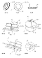
Ausführungsbeispiele der Erfindung werden nachfolgend anhand der Figuren näher erläutert. Diese zeigen teilweise in vereinfachten Darstellungen:
- Fig. 1
- eine ausschnittsweise perspektivische Darstellung einer als Plissee-Anlage ausgebildeten Beschattungsanlage mit einem austauschbaren geschlitzten Stoff und einem Sicherungselement,
- Fig. 2
- den in der
Fig. 1 mit einem Kreis gekennzeichneten Bereich in einer vergrößerten Darstellung, - Fig. 3
- eine Darstellung des Sicherungselements gemäß den
Fig. 1 und 2 , welches als Plättchen mit einem Einführschlitz ausgebildet ist, - Fig. 4A,4B,4C
- unterschiedliche Ausführungsvarianten des in
Fig. 3 dargestellten Plättchens im Bereich des Einführschlitzes, - Fig. 5A
- eine ausschnittsweise perspektivische Darstellung einer Beschattungsanlage mit einem als Schrankenelement ausgebildeten Sicherungselement,
- Fig. 5B
- den in der
Fig. 5A mit einem Kreis gekennzeichneten Bereich in vergrößerter Darstellung, - Fig. 6A
- eine ausschnittsweise Darstellung einer Beschattungsanlage mit als geschlitzte Ösen ausgebildeten Sicherungselementen,
- Fig. 6B
- eine vergrößerte Darstellung im Bereich der geschlitzten Öse,
- Fig. 7A,7B,7C
- verschiedene Ansichten der geschlitzten Öse,
- Fig. 8A
- eine ausschnittsweise Ansicht einer Beschattungsanlage mit einem plättchenförmigen Distanzelement,
- Fig. 8B
- den in der
Fig. 8A mit einem Kreis gekennzeichneten Bereich in einer vergrößerten Darstellung, - Fig. 9A
- eine ausschnittsweise Ansicht einer Beschattungsanlage mit einem Querstab als Distanzelement,
- Fig. 9B
- den in
Fig. 9A mit einem Kreis gekennzeichneten Bereich in vergrößerter Darstellung, - Fig. 10A
- eine ausschnittsweise Darstellung einer Beschattungsanlage mit einem als Wendel ausgebildeten Sicherungselement,
- Fig. 10B
- den in
Fig. 10A mit einem Kreis gekennzeichneten Bereich in vergrößerter Darstellung, - Fig. 11A
- eine ausschnittsweise Darstellung einer Beschattungsanlage mit einem als geschlitzte Hülse ausgebildeten Sicherungselement sowie
- Fig. 11B
- den in
Fig. 11A mit einem Kreis gekennzeichnete Bereich in vergrößerter Darstellung.
- Fig. 1
- a fragmentary perspective view of a designed as a pleated blind system with a replaceable slotted fabric and a fuse element,
- Fig. 2
- in the
Fig. 1 area marked with a circle in an enlarged view, - Fig. 3
- a representation of the securing element according to the
Fig. 1 and 2 , which is designed as a plate with an insertion slot, - FIGS. 4A, 4B, 4C
- different embodiments of the in
Fig. 3 shown platelet in the region of the insertion slot, - Fig. 5A
- a fragmentary perspective view of a shading system with a locking element designed as a security element,
- Fig. 5B
- in the
Fig. 5A area marked with a circle on an enlarged scale, - Fig. 6A
- a partial representation of a shading system with slotted eyelets designed as security elements,
- Fig. 6B
- an enlarged view in the area of the slotted eyelet,
- Figs. 7A, 7B, 7C
- different views of the slotted eyelet,
- Fig. 8A
- a partial view of a shading system with a platelet-shaped spacer element,
- Fig. 8B
- in the
Fig. 8A area marked with a circle in an enlarged view, - Fig. 9A
- a fragmentary view of a shading system with a cross bar as a spacer element,
- Fig. 9B
- the in
Fig. 9A area marked with a circle on an enlarged scale, - Fig. 10A
- a detail of a shading system with a helical fuse element formed,
- Fig. 10B
- the in
Fig. 10A area marked with a circle on an enlarged scale, - Fig. 11A
- a partial view of a shading system with a designed as a slotted sleeve fuse element and
- Fig. 11B
- the in
Fig. 11A Area marked with a circle on an enlarged scale.
In den Figuren sind gleich wirkende Teile mit den gleichen Bezugszeichen versehen.In the figures, like-acting parts are provided with the same reference numerals.
In
Die Profilschienen 4 zusammen mit dem zwischen ihnen befestigten Stoff 6 lassen sich in der montierten Endposition entlang von üblicherweise zumindest zwei Führungselementen 16 in einer Längsrichtung 14 entlang der zu beschattenden Fläche verschieben. Im Ausführungsbeispiel ist das Führungselement 16 als eine Führungsschnur, auch als Spannschnur bezeichnet, ausgebildet. Diese ist jeweils an einem unteren Rand und einem oberen Rand der zu beschattenden Fläche, beispielsweise eine Glasleiste, mit Hilfe eines sogenannten Schnurspanners 18 befestigt.The profile rails 4 together with the
Das Führungselement 16 ist durch den Stoff 6, und zwar durch die einzelnen Stofflamellen 10, durch Löcher 20 in Längsrichtung 14 lose hindurchgeführt. Die Löcher 20 fluchten in Längsrichtung 14 zueinander.The
Der Stoff 6 ist als ein austauschbarer Stoff ausgebildet. Er lässt sich in seitlicher Richtung 22, also senkrecht zur Querrichtung sowie senkrecht zur Längsrichtung 14 und damit in Richtung einer Flächennormalen der zu beschattenden Fläche von den Führungselementen 16 lösen. Hierzu sind in den Stoff 6 eine Vielzahl von Schlitzen 24 eingebracht, die jeweils ausgehend von den einzelnen Löchern 20 sich in seitlicher Richtung 22 zu einer hier als Rückseite 26 bezeichneten Seite des Stoffes 6 erstrecken. Die gegenüberliegende Seite wird als Vorderseite 28 bezeichnet. Die Rückseite 26 ist insbesondere die Fensterseite und die Vorderseite 28 die Raumseite. Das Austauschen des Stoffes 6 erfolgt hierbei derart, dass die Schlitze 24 aufgrund der Elastizität des Stoffes 6 aufgebogen werden, so dass das Führungselement 16 durch die Schlitze 24 seitlich nach außen geführt werden kann.The
Bei größeren Beschattungsanlagen beispielsweise mit einer Länge in Längsrichtung 14 von mehr als 120 cm kann dabei das Problem auftreten, dass die Führungselemente 16 beispielsweise bei einer Luftbewegung etc. selbsttätig aus den Schlitzen 24 herausrutschen.For larger shading systems, for example, with a length in the
Um dies zu verhindern, ist bei der Beschattungsanlage 2 nunmehr eine gewisse Anzahl von Sicherungselementen angeordnet, die ein solches ungewolltes seitliches Herausrutschen verhindern.In order to prevent this, now a certain number of securing elements are arranged in the shading system 2, which prevent such unwanted lateral slipping out.
Die nachfolgend beschriebenen Sicherungselemente lassen sich dabei grundsätzlich in drei Grundtypen unterscheiden, nämlich Verstärkungselemente 30, Distanzelemente 32 sowie Verdickungselemente 34. Die Grundfunktion dieser Sicherungselemente 30,32,34 besteht darin, dass sie die erforderliche Kraft zum seitlichen Abnehmen des Stoffes von den Führungselementen 16 zumindest erhöhen, so dass die beim normalen Betrieb auftretenden Kräfte nicht mehr für ein ungewolltes seitliches Herausgleiten ausreichen. Alternativ wird durch die Ausgestaltung des jeweiligen Sicherungselements, insbesondere in der Ausgestaltung als Distanzelement 32, ein seitliches Herausrutschen vollständig verhindert und es ist erst nach einer Entfernung des Distanzelements 32 möglich. Das Sicherungselement wirkt hierbei als ein Sperrelement, welches den Schlitz 24 sperrt und erst nach einem Entfernen oder zumindest Verschieben / Verdrehen des Sicherungselements den Schlitz 24 wieder freigibt.The securing elements described below can be fundamentally differentiated into three basic types, namely reinforcing elements 30, spacing elements 32 and thickening elements 34. The basic function of these securing elements 30, 32, 34 is that they at least have the required force for lateral removal of the substance from the
In Längsrichtung 14 betrachtet sind dabei nur an einigen wenigen Löchern 20 Sicherungselemente 30,32,34 angebracht. Ein Abstand a zwischen einem Sicherungselement 30,32,34 zu einem in Längsrichtung 14 benachbarten Sicherungselement 30,32,34 bzw. zu einer Profilschiene 4 beträgt dabei vorzugsweise mehr als 40 cm und insbesondere mehr als 60 cm und liegt beispielsweise bei 80 cm. Der Abstand a wird hierbei gemessen bei maximal vorgesehenem Auszug des Stoffes 6 in Längsrichtung 14.Viewed in the
Unterschiedliche Ausführungsvarianten der als Verstärkungselemente 30 ausgebildeten Sicherungselemente werden nachfolgend anhand der
Das in den
Der Einführschlitz 38 weist - unabhängig von der speziellen Ausgestaltung des Sicherungselements - dabei allgemein eine Schlitzbreite b1 auf, die kleiner als eine Breite b2 des Führungselements 16 ist. Im Ausführungsbeispiel der
In der
In den
Bei der Ausführungsvariante gemäß den
Das in den
Bei der Ausführungsvariante gemäß den
Bei der Ausführungsvariante gemäß den
Die Distanzelemente 32 sind - im Unterschied zu den Verstärkungselementen 30 an der Vorderseite 28 angebracht. Die Verstärkungselemente 30 sind demgegenüber an der Rückseite 26 angebracht.The spacer elements 32 are - in contrast to the reinforcing elements 30 attached to the front 28. The reinforcing elements 30 are on the other hand mounted on the
Schließlich ist in der Ausführungsvariante gemäß den
- 22
- Beschattungsanlageshading system
- 44
- Profilschienerail
- 66
- Stoffmaterial
- 88th
- Querrichtungtransversely
- 1010
- Stofflamellefabric louver
- 1212
- Faltkantefold
- 1414
- Längsrichtunglongitudinal direction
- 1616
- Führungselementguide element
- 1818
- Schnurspannercord tensioner
- 2020
- Lochhole
- 2222
- seitliche Richtunglateral direction
- 2424
- Schlitzslot
- 2626
- Rückseiteback
- 2828
- Vorderseitefront
- 3030
- Verstärkungselementreinforcing element
- 30a30a
- PlättchenTile
- 30b30b
- Schrankenelementbarrier member
- 30c30c
- geschlitzte Öseslotted eyelet
- 3232
- Distanzelementspacer
- 32a32a
- PlättchenTile
- 32b32b
- Querstabcross bar
- 32c32c
- Wendelspiral
- 3434
- Verdickungselementthickening element
- 34a34a
- Hülseshell
- 3636
- Führungslochhole
- 3838
- Einführschlitzinsertion
- 4040
- Kerbescore
- 4242
- Randbereichborder area
- 4343
- Fußbereichfooter
- 4444
- Nutgroove
- 4646
- Anlagekantecontact edge
- 4848
- Haltekerberetaining notch
- 5050
- Mittenbereichmid-range
- 5252
- Kragencollar
- aa
- Abstanddistance
- b1b1
- Schlitzbreiteslot width
- b2b2
- Breite FührungselementWide guide element
- dd
- Dickethickness
Claims (15)
dadurch gekennzeichnet,
dass im Bereich einiger der Löcher (20) ein Sicherungselement (30,32,34) gegen ein unbeabsichtigtes seitliches Herausrutschen der Führungselemente (16) aus den Löchern (20) angeordnet ist.Interchangeable fabric (6) for a shading installation (2) and shading installation (2), in particular a pleated installation comprising such a replaceable material (6), the fabric (6) being in particular a zigzag-folded fabric (6) which is in a longitudinal direction (14) and a transverse direction (8) and in the longitudinal direction (14) comprises a plurality of mutually aligned holes (20) for carrying a longitudinally extending (14) guide member (16) and further to a back (26) open Slots (24), wherein the slots (24) respectively from the holes (20) go out, so that the guide elements (16) laterally on the slots (24) in and out of the holes (20) can be executed and executed .
characterized,
in that in the region of some of the holes (20) a securing element (30, 32, 34) is arranged against unintentional lateral slipping out of the guide elements (16) from the holes (20).
dadurch gekennzeichnet,
dass das Sicherungselement (30,32,34) wahlweise als Verstärkungselement (30), als Distanzelement (32) oder als Verdickungselement (34) ausgebildet ist, wobei
characterized,
in that the securing element (30, 32, 34) is designed optionally as a reinforcing element (30), as a spacer element (32) or as a thickening element (34), wherein
dadurch gekennzeichnet,
dass das Sicherungselement (30,32,34) selbst ein Führungsloch (36) aufweist, durch das das Führungselement (16) im montierten Zustand lose geführt ist.Exchangeable material (6) and shading system (2) according to one of the preceding claims,
characterized,
that the securing element (30,32,34) itself has a guide hole (36) through which the guide element (16) in the mounted state is passed loosely.
dadurch gekennzeichnet,
dass das Sicherungselement (30,32,34) das jeweilige Führungselement (16) umgibt und durch seitliches Heranführen um das Führungselement (16) anbringbar ist und hierzu insbesondere einen seitlichen Einführungsschlitz (38) zum seitlichen Einführen des Führungselements (16) aufweist.Exchangeable material (6) and shading system (2) according to one of the preceding claims,
characterized,
in that the securing element (30, 32, 34) surrounds the respective guide element (16) and can be attached to the guide element (16) by lateral introduction and, in particular, has a lateral insertion slot (38) for lateral insertion of the guide element (16).
dadurch gekennzeichnet,
dass der Einführungsschlitz (38) elastisch aufbiegbar ist.Interchangeable fabric (6) and shading system (2) according to the preceding claim,
characterized,
that the insertion slot (38) is elastically aufgebiegbar.
dadurch gekennzeichnet,
dass der Einführungsschlitz (38)
characterized,
that the insertion slot (38)
dadurch gekennzeichnet,
dass das Sicherungselement (30,32) plättchenförmig ausgebildet ist.Exchangeable material (6) and shading system (2) according to one of the preceding claims,
characterized,
that the securing element (30,32) is formed platelet-shaped.
dadurch gekennzeichnet,
dass das Sicherungselement (30,32,34), insbesondere das Verstärkungselement (30) am Stoff (6) befestigt, insbesondere aufgeklebt ist.Exchangeable material (6) and shading system (2) according to one of the preceding claims,
characterized,
in that the securing element (30, 32, 34), in particular the reinforcing element (30), is fastened to the fabric (6), in particular adhesively bonded thereto.
dadurch gekennzeichnet,
dass das Sicherungselement (30,32,34) jeweils lokal nur für ein einziges Loch (20) ausgebildet ist oder alternativ sich in Querrichtung (8) über mehrere Löcher (20) erstreckt und hierzu insbesondere als ein Querstab (32b) oder als eine Querplatte ausgebildet istInterchangeable fabric (6) and shading system (2)
characterized,
that the securing element (30,32,34) is formed locally in each case for only one hole (20) or alternatively in the transverse direction (8) via a plurality of holes (20) and this, in particular as a transverse bar (32b) or as a transverse plate is trained
dadurch gekennzeichnet,
dass in Längsrichtung (14) des Stoffes (6) allenfalls einigen der Löcher (20) ein Sicherungselement (30,32,34) zugeordnet ist und Löcher (20), denen ein Sicherungselement (30,32,34) zugeordnet ist, bevorzugt einen Abstand (a) zueinander oder zu einer randseitigen Befestigung des Stoffes (6) von mehreren 10 cm, insbesondere von zumindest 40 oder 60 cm aufweisen, wobei das Sicherungselement (30, 32, 34) insbesondere lediglich in einem mittleren Bereich angebracht ist.Exchangeable material (6) and shading system (2) according to one of the preceding claims,
characterized,
that in the longitudinal direction (14) of the substance (6) at most some of the holes (20) is associated with a securing element (30,32,34) and holes (20) to which a securing element (30,32,34) is assigned, preferably one Distance (a) to each other or to a peripheral attachment of the fabric (6) of several 10 cm, in particular of at least 40 or 60 cm, wherein the securing element (30, 32, 34) is mounted in particular only in a central region.
dadurch gekennzeichnet,
dass das Sicherungselement (32,34) eine Anlagekante (46) aufweist, mit der es an einer Faltenkante (12) des Stoffes (6) anliegtExchangeable material (6) and shading system (2) according to one of the preceding claims,
characterized,
in that the securing element (32, 34) has a contact edge (46) with which it bears against a fold edge (12) of the substance (6)
dadurch gekennzeichnet,
dass das Sicherungselement (32), insbesondere das Distanzelement (32) auf seiner dem Führungselement (16) zugewandten Seite zumindest eine Haltekerbe (48) aufweist, in der das Führungselement (16) im montierten Zustand einliegt.Exchangeable material (6) and shading system (2) according to one of the preceding claims,
characterized,
that the securing element (32), in particular the distance element (32) on its side facing the guide element (16) facing side at least one retaining notch (48), in which the guide element (16) rests in the mounted state.
dadurch gekennzeichnet,
dass das Sicherungselement (30,32,34) in einer Ausgestaltung als Verstärkungselement (30) wahlweise ausgebildet ist als
characterized,
that the securing element (30,32,34) is formed in one embodiment as a reinforcing member (30) either as
dadurch gekennzeichnet,
dass das Sicherungselement (30,32,34) an dem Führungselement (16) reibend anliegt, so dass ein ungewolltes Verrutschen des Stoffes (6) relativ zum Führungselement (16) verhindert ist.Exchangeable material (6) and shading system (2) according to one of the preceding claims,
characterized,
that the securing element (30,32,34) on the guide element (16) rests frictionally, so that unintentional slipping of the substance (6) relative to the guide element (16) is prevented.
Priority Applications (1)
| Application Number | Priority Date | Filing Date | Title |
|---|---|---|---|
| EP15158116.2A EP3064700A1 (en) | 2015-03-06 | 2015-03-06 | Replaceable material for a shading device and shading device with such a material |
Applications Claiming Priority (1)
| Application Number | Priority Date | Filing Date | Title |
|---|---|---|---|
| EP15158116.2A EP3064700A1 (en) | 2015-03-06 | 2015-03-06 | Replaceable material for a shading device and shading device with such a material |
Publications (1)
| Publication Number | Publication Date |
|---|---|
| EP3064700A1 true EP3064700A1 (en) | 2016-09-07 |
Family
ID=52627100
Family Applications (1)
| Application Number | Title | Priority Date | Filing Date |
|---|---|---|---|
| EP15158116.2A Withdrawn EP3064700A1 (en) | 2015-03-06 | 2015-03-06 | Replaceable material for a shading device and shading device with such a material |
Country Status (1)
| Country | Link |
|---|---|
| EP (1) | EP3064700A1 (en) |
Cited By (1)
| Publication number | Priority date | Publication date | Assignee | Title |
|---|---|---|---|---|
| DE202016106428U1 (en) | 2016-11-16 | 2017-02-20 | Achim Lienert | Foldable fabric and shading system with such a foldable fabric |
Citations (2)
| Publication number | Priority date | Publication date | Assignee | Title |
|---|---|---|---|---|
| US20110100562A1 (en) * | 2009-10-30 | 2011-05-05 | Robertson Richard W | Roman shade with protected operating cords |
| DE202014104192U1 (en) | 2014-09-05 | 2014-09-18 | Achim Lienert | Shading system with horizontal folding blades |
-
2015
- 2015-03-06 EP EP15158116.2A patent/EP3064700A1/en not_active Withdrawn
Patent Citations (2)
| Publication number | Priority date | Publication date | Assignee | Title |
|---|---|---|---|---|
| US20110100562A1 (en) * | 2009-10-30 | 2011-05-05 | Robertson Richard W | Roman shade with protected operating cords |
| DE202014104192U1 (en) | 2014-09-05 | 2014-09-18 | Achim Lienert | Shading system with horizontal folding blades |
Cited By (2)
| Publication number | Priority date | Publication date | Assignee | Title |
|---|---|---|---|---|
| DE202016106428U1 (en) | 2016-11-16 | 2017-02-20 | Achim Lienert | Foldable fabric and shading system with such a foldable fabric |
| EP3323974A1 (en) | 2016-11-16 | 2018-05-23 | Achim Lienert | Foldable fabric as well as shading installation with such a foldable fabric |
Similar Documents
| Publication | Publication Date | Title |
|---|---|---|
| DE69807438T2 (en) | UNIVERSAL FASTENING AND PARALLEL GUIDE DEVICE FOR A WINDOW SHIELDING | |
| DE69909153T2 (en) | Automatic lock for blinds | |
| DE202009016230U1 (en) | Retaining device for Roman blind pearl ropes | |
| DE2304809C3 (en) | Bottom bar of a slatted blind that can be gathered with attached elevator, supporting and turning elements | |
| EP3064700A1 (en) | Replaceable material for a shading device and shading device with such a material | |
| DE202006000857U1 (en) | Roller blind arrangement for windows comprises a roller strip and a set of left and right fixing supports | |
| DE202009015473U1 (en) | Venetian blind | |
| DE10031275C1 (en) | Flexible belt, for hanging up armored roller shutter, has stabilizing extensions either side of holding tongue which is bent out or off-set parallel to plane of belt | |
| DE202012001975U1 (en) | Panel curtain system | |
| DE3606554A1 (en) | Spring element for connecting the shutter of a roller blind to the roller-blind shaft | |
| DE202015101141U1 (en) | Replaceable fabric for a shading system and shading system with such a replaceable material | |
| EP1635028A2 (en) | Roman shade | |
| EP1081326B1 (en) | Fastening system for a building element like winding roll or Roman shade rod to a support rail for window decorations | |
| DE29603976U1 (en) | Auxiliary device for attaching a rollable element to a roll tube | |
| DE202018103057U1 (en) | Plisseejalousie | |
| EP3655612B1 (en) | Pleated blind with telescopic guide rail | |
| EP1712164B1 (en) | Roller shaft for a Roman shade and Roman shade with a roller shaft | |
| DE1509538C (en) | Slat blind with vertically arranged slats that can be pivoted together about their longitudinal axis | |
| DE4244334C2 (en) | Raff curtain | |
| DE20305389U1 (en) | Spring device for securing e.g. roller shutters to winding shaft, has main part releasably secured to end section for securing to shutters | |
| EP4402335A1 (en) | Vertical blind comprising multiple strip-shaped shading elements | |
| DE202006013861U1 (en) | Tilting device for a roller casing for gathered curtains conceals a gathering mechanism and a fastening for the gathered curtains | |
| DE3037703A1 (en) | Venetian blinds with guide elements arranged at the ends of the slats | |
| DE2705250C3 (en) | Device for winding belts, tapes or the like. especially of roller shutter belts | |
| EP3323974A1 (en) | Foldable fabric as well as shading installation with such a foldable fabric |
Legal Events
| Date | Code | Title | Description |
|---|---|---|---|
| PUAI | Public reference made under article 153(3) epc to a published international application that has entered the european phase |
Free format text: ORIGINAL CODE: 0009012 |
|
| AK | Designated contracting states |
Kind code of ref document: A1 Designated state(s): AL AT BE BG CH CY CZ DE DK EE ES FI FR GB GR HR HU IE IS IT LI LT LU LV MC MK MT NL NO PL PT RO RS SE SI SK SM TR |
|
| AX | Request for extension of the european patent |
Extension state: BA ME |
|
| STAA | Information on the status of an ep patent application or granted ep patent |
Free format text: STATUS: THE APPLICATION IS DEEMED TO BE WITHDRAWN |
|
| 18D | Application deemed to be withdrawn |
Effective date: 20170308 |