EP3064689B1 - Hold-open device for a door - Google Patents
Hold-open device for a door Download PDFInfo
- Publication number
- EP3064689B1 EP3064689B1 EP15203032.6A EP15203032A EP3064689B1 EP 3064689 B1 EP3064689 B1 EP 3064689B1 EP 15203032 A EP15203032 A EP 15203032A EP 3064689 B1 EP3064689 B1 EP 3064689B1
- Authority
- EP
- European Patent Office
- Prior art keywords
- hold
- retaining device
- energy
- open
- voltage
- Prior art date
- Legal status (The legal status is an assumption and is not a legal conclusion. Google has not performed a legal analysis and makes no representation as to the accuracy of the status listed.)
- Active
Links
- 238000000034 method Methods 0.000 claims description 48
- 230000007547 defect Effects 0.000 claims description 37
- 238000012546 transfer Methods 0.000 claims description 33
- 230000002950 deficient Effects 0.000 claims description 4
- 230000008707 rearrangement Effects 0.000 claims description 2
- 238000004146 energy storage Methods 0.000 description 62
- 239000000872 buffer Substances 0.000 description 41
- 230000009969 flowable effect Effects 0.000 description 15
- 238000012360 testing method Methods 0.000 description 14
- 238000012544 monitoring process Methods 0.000 description 11
- 239000003990 capacitor Substances 0.000 description 10
- 238000005259 measurement Methods 0.000 description 9
- 239000000779 smoke Substances 0.000 description 5
- 230000032683 aging Effects 0.000 description 3
- 230000005611 electricity Effects 0.000 description 3
- 125000004122 cyclic group Chemical group 0.000 description 2
- 238000011161 development Methods 0.000 description 2
- 230000018109 developmental process Effects 0.000 description 2
- 238000010586 diagram Methods 0.000 description 2
- 238000009420 retrofitting Methods 0.000 description 2
- 230000001960 triggered effect Effects 0.000 description 2
- 230000004888 barrier function Effects 0.000 description 1
- 230000001419 dependent effect Effects 0.000 description 1
- 238000013461 design Methods 0.000 description 1
- 238000001514 detection method Methods 0.000 description 1
- 238000007599 discharging Methods 0.000 description 1
- 230000000694 effects Effects 0.000 description 1
- 238000010438 heat treatment Methods 0.000 description 1
- 230000000977 initiatory effect Effects 0.000 description 1
- 238000009434 installation Methods 0.000 description 1
- 239000011505 plaster Substances 0.000 description 1
- 239000000126 substance Substances 0.000 description 1
Images


Classifications
-
- E—FIXED CONSTRUCTIONS
- E05—LOCKS; KEYS; WINDOW OR DOOR FITTINGS; SAFES
- E05F—DEVICES FOR MOVING WINGS INTO OPEN OR CLOSED POSITION; CHECKS FOR WINGS; WING FITTINGS NOT OTHERWISE PROVIDED FOR, CONCERNED WITH THE FUNCTIONING OF THE WING
- E05F1/00—Closers or openers for wings, not otherwise provided for in this subclass
- E05F1/002—Closers or openers for wings, not otherwise provided for in this subclass controlled by automatically acting means
- E05F1/006—Closers or openers for wings, not otherwise provided for in this subclass controlled by automatically acting means by emergency conditions, e.g. fire
-
- E—FIXED CONSTRUCTIONS
- E05—LOCKS; KEYS; WINDOW OR DOOR FITTINGS; SAFES
- E05F—DEVICES FOR MOVING WINGS INTO OPEN OR CLOSED POSITION; CHECKS FOR WINGS; WING FITTINGS NOT OTHERWISE PROVIDED FOR, CONCERNED WITH THE FUNCTIONING OF THE WING
- E05F3/00—Closers or openers with braking devices, e.g. checks; Construction of pneumatic or liquid braking devices
- E05F3/22—Additional arrangements for closers, e.g. for holding the wing in opened or other position
- E05F3/221—Mechanical power-locks, e.g. for holding the wing open or for free-moving zones
- E05F3/222—Mechanical power-locks, e.g. for holding the wing open or for free-moving zones electrically operated
-
- E—FIXED CONSTRUCTIONS
- E05—LOCKS; KEYS; WINDOW OR DOOR FITTINGS; SAFES
- E05Y—INDEXING SCHEME RELATING TO HINGES OR OTHER SUSPENSION DEVICES FOR DOORS, WINDOWS OR WINGS AND DEVICES FOR MOVING WINGS INTO OPEN OR CLOSED POSITION, CHECKS FOR WINGS AND WING FITTINGS NOT OTHERWISE PROVIDED FOR, CONCERNED WITH THE FUNCTIONING OF THE WING
- E05Y2201/00—Constructional elements; Accessories therefore
- E05Y2201/40—Motors; Magnets; Springs; Weights; Accessories therefore
- E05Y2201/46—Magnets
- E05Y2201/462—Electromagnets
-
- E—FIXED CONSTRUCTIONS
- E05—LOCKS; KEYS; WINDOW OR DOOR FITTINGS; SAFES
- E05Y—INDEXING SCHEME RELATING TO HINGES OR OTHER SUSPENSION DEVICES FOR DOORS, WINDOWS OR WINGS AND DEVICES FOR MOVING WINGS INTO OPEN OR CLOSED POSITION, CHECKS FOR WINGS AND WING FITTINGS NOT OTHERWISE PROVIDED FOR, CONCERNED WITH THE FUNCTIONING OF THE WING
- E05Y2400/00—Electronic control; Power supply; Power or signal transmission; User interfaces
- E05Y2400/10—Electronic control
- E05Y2400/30—Electronic control of motors
- E05Y2400/40—Control units therefore
-
- E—FIXED CONSTRUCTIONS
- E05—LOCKS; KEYS; WINDOW OR DOOR FITTINGS; SAFES
- E05Y—INDEXING SCHEME RELATING TO HINGES OR OTHER SUSPENSION DEVICES FOR DOORS, WINDOWS OR WINGS AND DEVICES FOR MOVING WINGS INTO OPEN OR CLOSED POSITION, CHECKS FOR WINGS AND WING FITTINGS NOT OTHERWISE PROVIDED FOR, CONCERNED WITH THE FUNCTIONING OF THE WING
- E05Y2400/00—Electronic control; Power supply; Power or signal transmission; User interfaces
- E05Y2400/10—Electronic control
- E05Y2400/45—Control modes
- E05Y2400/458—Control modes for generating service signals
-
- E—FIXED CONSTRUCTIONS
- E05—LOCKS; KEYS; WINDOW OR DOOR FITTINGS; SAFES
- E05Y—INDEXING SCHEME RELATING TO HINGES OR OTHER SUSPENSION DEVICES FOR DOORS, WINDOWS OR WINGS AND DEVICES FOR MOVING WINGS INTO OPEN OR CLOSED POSITION, CHECKS FOR WINGS AND WING FITTINGS NOT OTHERWISE PROVIDED FOR, CONCERNED WITH THE FUNCTIONING OF THE WING
- E05Y2400/00—Electronic control; Power supply; Power or signal transmission; User interfaces
- E05Y2400/10—Electronic control
- E05Y2400/50—Fault detection
- E05Y2400/512—Fault detection of electric power
-
- E—FIXED CONSTRUCTIONS
- E05—LOCKS; KEYS; WINDOW OR DOOR FITTINGS; SAFES
- E05Y—INDEXING SCHEME RELATING TO HINGES OR OTHER SUSPENSION DEVICES FOR DOORS, WINDOWS OR WINGS AND DEVICES FOR MOVING WINGS INTO OPEN OR CLOSED POSITION, CHECKS FOR WINGS AND WING FITTINGS NOT OTHERWISE PROVIDED FOR, CONCERNED WITH THE FUNCTIONING OF THE WING
- E05Y2400/00—Electronic control; Power supply; Power or signal transmission; User interfaces
- E05Y2400/60—Power supply; Power or signal transmission
- E05Y2400/61—Power supply
- E05Y2400/612—Batteries
-
- E—FIXED CONSTRUCTIONS
- E05—LOCKS; KEYS; WINDOW OR DOOR FITTINGS; SAFES
- E05Y—INDEXING SCHEME RELATING TO HINGES OR OTHER SUSPENSION DEVICES FOR DOORS, WINDOWS OR WINGS AND DEVICES FOR MOVING WINGS INTO OPEN OR CLOSED POSITION, CHECKS FOR WINGS AND WING FITTINGS NOT OTHERWISE PROVIDED FOR, CONCERNED WITH THE FUNCTIONING OF THE WING
- E05Y2800/00—Details, accessories and auxiliary operations not otherwise provided for
- E05Y2800/20—Combinations of elements
- E05Y2800/246—Combinations of elements with at least one element being redundant
-
- E—FIXED CONSTRUCTIONS
- E05—LOCKS; KEYS; WINDOW OR DOOR FITTINGS; SAFES
- E05Y—INDEXING SCHEME RELATING TO HINGES OR OTHER SUSPENSION DEVICES FOR DOORS, WINDOWS OR WINGS AND DEVICES FOR MOVING WINGS INTO OPEN OR CLOSED POSITION, CHECKS FOR WINGS AND WING FITTINGS NOT OTHERWISE PROVIDED FOR, CONCERNED WITH THE FUNCTIONING OF THE WING
- E05Y2800/00—Details, accessories and auxiliary operations not otherwise provided for
- E05Y2800/25—Emergency conditions
- E05Y2800/252—Emergency conditions the elements functioning only in case of emergency
-
- E—FIXED CONSTRUCTIONS
- E05—LOCKS; KEYS; WINDOW OR DOOR FITTINGS; SAFES
- E05Y—INDEXING SCHEME RELATING TO HINGES OR OTHER SUSPENSION DEVICES FOR DOORS, WINDOWS OR WINGS AND DEVICES FOR MOVING WINGS INTO OPEN OR CLOSED POSITION, CHECKS FOR WINGS AND WING FITTINGS NOT OTHERWISE PROVIDED FOR, CONCERNED WITH THE FUNCTIONING OF THE WING
- E05Y2800/00—Details, accessories and auxiliary operations not otherwise provided for
- E05Y2800/40—Protection
- E05Y2800/404—Protection against component faults or failure
-
- E—FIXED CONSTRUCTIONS
- E05—LOCKS; KEYS; WINDOW OR DOOR FITTINGS; SAFES
- E05Y—INDEXING SCHEME RELATING TO HINGES OR OTHER SUSPENSION DEVICES FOR DOORS, WINDOWS OR WINGS AND DEVICES FOR MOVING WINGS INTO OPEN OR CLOSED POSITION, CHECKS FOR WINGS AND WING FITTINGS NOT OTHERWISE PROVIDED FOR, CONCERNED WITH THE FUNCTIONING OF THE WING
- E05Y2800/00—Details, accessories and auxiliary operations not otherwise provided for
- E05Y2800/40—Protection
- E05Y2800/414—Protection against high or low temperatures
- E05Y2800/416—Protection against high or low temperatures against fire
Definitions
- the invention relates to a locking arrangement for a door, with a holding device for locking the door, in particular in an open position, wherein the holding device is transferred under supply of electrical energy from a determining state to a releasing state, according to the preamble of claim 1. Further The invention relates to a method for operating a locking arrangement.
- Locking arrangements are widely used in building services engineering for door and gate systems, which are equipped with fire barriers in accordance with the applicable regulations.
- the locking arrangement allows a door equipped with a mounted door closer to be kept open either at a fixed or selected angle until it is electrically triggered.
- the individual components of the locking arrangement are connected to the building power network for power supply.
- the WO92 / 04519 A1 discloses a locking arrangement in which, with the supply of energy, the locking arrangement is transferred to the releasing state.
- the energy is provided by a battery.
- the locking arrangement is transferred when falling below a battery voltage and when removing the battery in the releasing state.
- the invention has for its object to provide a locking arrangement and a method for operating a locking arrangement, which avoids the aforementioned disadvantage, in particular to provide a locking arrangement and methods that are easy to install.
- the locking arrangement is designed to transfer the retaining device from the locking state into the releasing state if a defect occurs in the intended supply of the retaining device with electric current and / or a predetermined voltage value for an energy storage unit which is responsible for the supply is used by electrical energy for the holding device, is exceeded.
- the locking arrangement is designed to transfer by supplying electrical energy, the holding device of a detecting state in a releasing state.
- the holding device can be in the ascertaining and / or releasing state without the supply of electrical energy. This enables energy-saving operation of the locking arrangement. Due to the energy-saving operation, it is possible to dispense with a wiring to the building electricity network and thus provide a mounting-friendly Feststellan onion.
- Under the determining state of the holding device is understood in particular a state that is for detecting the door is used by the holding device.
- Under the releasing state is understood in particular a state in which the holding device has released the door, so that the door is movable, in particular closable, is.
- a door operator in addition to the locking arrangement, is allowed to close the door from the previously held position.
- the transfer of the holding device from the determining to the releasing state thus serves in particular for releasing the door.
- the holding device is always transferred to the releasing state when a transfer at a later date, especially in a fire, can no longer be guaranteed safe.
- the transfer to the releasing state always takes place when only the energy for a predetermined number of transfers, in particular for transfer, is reliably available and / or when the initiation of the transfer into the releasing state is no longer reliably ensured.
- a defect in the intended supply of the holding device with electric current is therefore also to be understood as defects which relate to the control of the transfer.
- the locking device is particularly preferably battery operated and thus independent of an external power supply.
- the locking arrangement is in particular free of an electrical connection to a building electricity network.
- the energy storage unit may comprise one or more electrochemical energy stores.
- the electrochemical energy store can be designed as a battery or as an accumulator.
- the multiple energy storage can be connected in series and / or in parallel. For example, several, z. B. two, energy storage in series and the rows of energy storage each other in turn be connected in parallel.
- the energy storage unit may be formed as an energy storage package with multiple energy storage.
- the locking arrangement preferably comprises a danger detector, in particular a fire and / or smoke detector.
- the danger detector can, in particular in the case of a fire, transmit a triggering signal to a control device of the locking arrangement. Thereafter, the control device controls the holding device, so that the holding device is transferred from the determining to the releasing state.
- the locking arrangement may comprise a sliding element in a slide rail.
- the sliding element can be detected and / or released within a slide rail. That is, in a transfer of the holding device from the locking to the releasing state, the sliding element is released, so that the sliding element is movable in the slide rail.
- the sliding element can be connected to the door.
- the holding device in particular a holding mechanism of the holding device, blocks the sliding element in the slide rail in the locking state.
- the sliding element In the releasing state, the sliding element is movably arranged in the slide rail, so that the door is also movable.
- a holding device is in the DE 10 2010 061 246 A1 disclosed.
- the energy storage unit, the slide, the danger detector, the holding device and the control device for arranging on a frame of the door may be provided.
- the energy storage unit, the slide rail, the danger detector, the holding device and the control device are arranged in a common housing.
- the holding device is designed to determine the door in the open position.
- the locking arrangement is preferably designed to transmit the holding device in the releasing state when the trigger signal is emitted, so that the door can be closed.
- the locking arrangement has at least one energy buffer, which is designed in particular as at least one capacitor element, in which an amount of electrical energy can be stored, by which the holding device can be transferred from the ascertaining state into the releasing state.
- the sliding element can be released by the amount of energy.
- an energy buffer is provided, even in the case of a defect of the energy storage unit or an electrical connection line of the energy storage unit, the holding device can be transferred to the releasing state at least once.
- the installation of the intermediate energy store can thus contribute to the reliability of the locking arrangement operating on the working current principle.
- the recommended maximum continuous current of an energy storage of the energy storage unit however, z. B. between 20 mA and 200 mA, preferably between 60 mA and 120 mA.
- the maximum pulsed discharge current of the energy store can be between 80 mA and 400 mA, preferably between 150 mA and 250 mA.
- the energy buffer is in particular electrically connected between the energy storage unit and the holding device.
- the amount of energy of the energy storage unit can be supplied only via the energy buffer of the holding device.
- the Energy buffer can be rechargeable in particular only from the energy storage unit.
- the control device in particular a microcontroller, can in particular be designed to initiate that the holding device is transferred from the determining to the releasing state if a defect occurs in the intended supply of the holding device with electric current and / or the predetermined voltage value is undershot , In this case, the control device can in particular detect the defect and / or the undershooting of the predetermined voltage value.
- a first voltage measuring point for determining a voltage value characterizing the electrical voltage of the energy storage unit.
- the holding device is transferred to the releasing state.
- the first voltage measuring point can be connected electrically in parallel to the energy storage unit and the control device.
- the predefined voltage value may in particular be a voltage value that can be determined at the first voltage measuring point and that characterizes the predefined voltage of the energy storage unit.
- the voltage measurement can be carried out at first predetermined time intervals.
- the first predetermined time intervals can be stored in the control device.
- the control device can perform the voltage measurement.
- a voltage divider may be provided.
- the first voltage measuring point may have a voltmeter which transmits the determined voltage value to the control unit.
- the control unit compares the determined with the predetermined voltage value and can optionally transfer the holding device in the releasing state.
- the predetermined voltage value can be stored in the control device.
- a predetermined threshold value can be provided for a voltage value determined by the first voltage measuring point, in which case a Warning is issued.
- a warning for example, a lighting element of the locking arrangement can shine.
- the light element z. B. flashing The warning informs an operator that the energy storage unit is about to be replaced.
- the individual electrochemical energy store can have at least a ratio V1 of the nominal voltage to a recommended maximum continuous current of 10 ⁇ ⁇ V1 ⁇ 40 ⁇ , preferably 15 ⁇ ⁇ V1 ⁇ 30 ⁇ . Additionally or alternatively, the individual energy store may have a ratio V2 of the nominal voltage to a maximum pulsed discharge current of 20 ⁇ ⁇ V2 ⁇ 100 ⁇ , preferably 30 ⁇ ⁇ V2 ⁇ 70 ⁇ . As a result, a critical heating of the energy storage is excluded. Additionally or alternatively, a fuse may be provided in the energy storage unit. In this way, it is thus possible to contribute to the reliability of the locking arrangement operating on the working current principle.
- a defect in the intended supply of the holding device with electrical current is preferably present when there is a short circuit and / or an interruption within the energy storage unit and / or in the connection line of the energy storage unit.
- the holding device is transferred from the determining to the releasing state.
- the energy buffer store can provide the electrical energy.
- the short circuit or the interruption can be effected by the voltage value determined at the first voltage measuring point, which is below the predetermined voltage value.
- the holding device has an electrically flowable component.
- the electrically flowable component can, for. B. may be formed as a magnetic coil.
- the component is an element of the holding device, for. B. an anchor, movable, through which the transfer takes place in the releasing state.
- the component can be part of an actuator, z.
- the component which can flow through electrically can be flowed through in particular with electric current with different current directions. The magnetic fields generated thereby can move the element between two positions corresponding to the detecting state and the releasing state. This is again on the DE 10 2010 061 246 A1 directed.
- the locking arrangement can have a measuring point for determining an electrical current flowing through the component which can flow electrically, wherein there is a defect in the intended supply of the holding device with electric current if the determined current strength is outside a predetermined value range.
- the control device can determine the current intensity.
- a resistor may be provided at the measuring point.
- the current intensity is determined via a measurement of a voltage applied to the resistor.
- the current measuring point can have an ammeter which transmits the measured current intensity to the control unit.
- the control unit checks whether the measured current strength is within the predetermined value range and, if not, allows the holding device to be released.
- An upper limit of the value range may, for. B. serve to detect a short circuit.
- a lower limit of the value range can, for. B. serve to determine if there is an interruption of the circuit and / or if there is a sufficient current to generate a sufficient magnetic field for the transfer of the holding device in the releasing state.
- the determination of the current intensity can be carried out at second predetermined time intervals.
- the second predetermined time intervals can be stored in the control device.
- the second predetermined time intervals can be identical in particular. For example, such a measurement may be performed every twenty four hours. So that the current flow through the component which can flow through electrically does not lead to a release into the releasing state, it can be provided that the electrically flowable component is energized with such a polarity to carry out the measurement, which is carried out for testing purposes, that the current supply is ineffective on the state of the holding device is. Additionally or alternatively, the current intensity is determined at a triggered by the trigger signal transfer to the releasing state.
- the energy storage unit can be connected via a voltage converter to the energy buffer. Via the voltage converter, a higher electrical voltage can be generated in the energy buffer than in the energy storage unit. In particular, via the voltage converter, the control device can cause a charging of the energy buffer.
- a second voltage measuring point for determining a voltage value characterizing the electrical voltage of the intermediate energy store.
- the second voltage measuring point can be electrically connected in parallel to the energy buffer and the control device.
- the voltage measurement at the second voltage measuring point can be carried out at predetermined third time intervals.
- the third predetermined time intervals can be stored in the control device.
- the control device may perform the voltage measurement at the second voltage measurement point.
- a voltage divider may be provided at the second voltage measuring point.
- the second voltage measuring point can have a voltmeter which transmits the measured voltage value to the control unit.
- the voltage value characterizing the intermediate energy storage device which was determined at the second voltage measurement point, is preferably compared with a nominal voltage value. If the voltage value falls below the setpoint voltage value by a predetermined amount, in particular the control device causes the energy buffer to be charged to the setpoint voltage value.
- the nominal voltage value can be stored in the control unit.
- the predetermined time intervals can be identical in particular. This ensures that the energy buffer has stored a sufficient amount of energy to transfer the holding device in the releasing state and has not over-discharged over time.
- the control unit can check whether the energy buffer reaches the target voltage value within the predetermined charging period. If the target voltage value is not reached within the charging period, there is a defect in the intended supply of the holding device with electrical energy. In this case, the holding device is transferred to the releasing state. For example, there may be a short circuit in the energy buffer or the voltage converter may be defective. Also, the energy buffer may be aged and have a small capacity, so that the charge on the target voltage value is too fast.
- the predefined charging time interval ⁇ t 4 can thus be limited by an upper limit value t above and a lower limit value t below greater than zero.
- t can be selected below and t above depending on the amount to be undershot and the capacitance of the capacitor element.
- t below z. B. between 0.1 s and 10 s, preferably between 1 s and 4 s.
- t can be stored at the top of z. B. between 10 s and 60 s, preferably between 5 s and 30 s be selected.
- z. B by 10% to 50%, preferably by 20% to 40%, taken into account.
- the maximum value for the voltage drop and / or the discharge period can be stored in the control device.
- the comparison between the maximum value and the determined voltage drop can be made by the control device.
- the energy buffer is preferably discharged for determining the voltage drop in the discharge period by carrying out the test described above, in which the component which can flow through electrically is energized with such a polarity that the current supply is ineffective on the state of the holder.
- both the current flow through the electrically flowable component and the capacity of the energy buffer can be overhauled in one operation.
- the locking arrangement has at least two mutually redundant energy buffers and / or at least two mutually redundant electrically flowable components.
- the transfer of the holding device can be reliably effected in the releasing position.
- the serious defect can z. B. be a short circuit in the energy buffer.
- Each electrically flowable component is designed such that without the help of further electrically flowable component of the releasing state can be brought about.
- At least two subsystems are provided, each comprising at least one energy buffer and an electrically flowable component, wherein the subsystems are each configured independently of each other.
- the subsystems are in particular redundant to each other.
- the locking arrangement has at least two control devices which monitor each other, wherein there is a defect in the intended supply of the holding device with electric current, if a control device is faulty.
- one of the control devices can detect a defect in the other control device and cause the transfer of the holding device in the releasing state.
- the control devices can monitor at predetermined monitoring intervals, which are stored in particular in the control devices.
- the control devices monitor themselves.
- CPU and RAM test can be performed.
- self-monitoring is performed at regular, predetermined self-monitoring intervals. Is activated during monitoring Error, z. B. detected in the CPU or RAM test, a defect in the provided supply of the holding device is detected with electric current and transferred the holding device in particular by the further intact control device in the releasing state.
- the at least two control devices can each be part of a subsystem.
- each subsystem may range from receiving a trigger signal to the electrically flowable component of the fixture.
- the holding device can be transferred independently of the other subsystem in the releasing state.
- the control device may be in a power saving mode. If the control device can not leave the energy saving mode, then the holding device is transferred to the releasing state. This defect can be detected in particular by another control device.
- a push-button is provided in order to allow a re-arrangement of the holding device in the determining state after a transfer to the releasing state, in particular after receiving a fire alarm signal and / or a change of the energy storage unit. It may also be that after remedying a defect, in particular a short circuit z. B. in the energy buffer or in the energy storage unit, by pressing the button and a self-test re-transfer to the determining state may be possible.
- a capacitor is provided to the case of failure of the power supply unit, the control device with electrical energy supply.
- each control device is assigned a capacitor.
- at least the amount of energy that is necessary for the control device to initiate the transfer of the holding device into the releasing state can be stored in the capacitor.
- the predetermined voltage value U V1 may be a voltage value of the energy storage unit, in which only once the holding device secured in the releasing state can be transferred. Additionally or alternatively, the predetermined voltage value U V1 as a function of the nominal voltage U N of the energy storage unit as a value from an interval 0.5 * U N ⁇ U V1 ⁇ 0.9 * U N , preferably 0.65 * U N ⁇ U V1 ⁇ 0.9 * U N , more preferably 0.75 * U N ⁇ U V1 ⁇ 0.85 * U N , be predetermined.
- the predetermined voltage value U V1 may be a value between 5V and 6.5V, preferably between 5.5V and 6.3V.
- the threshold value U S is above the predetermined voltage value U V1 .
- the threshold value can be a value from an interval 0.7 * U N ⁇ U S ⁇ 0.98 * U N , preferably 0.8 * U N ⁇ U S ⁇ 0.98 * U N , particularly preferably 0.9 * U N ⁇ U S ⁇ 0.95 * U N.
- the threshold value U S may be a value between 6 V and 7.0 V, preferably between 6.5 V and 6.9 V.
- the target voltage value U V2 is to be selected such that, depending on the capacitance of the capacitor element used, the charge amount for transferring the holding device into the releasing state is sufficient.
- the charge amount suffices for an n-fold transfer to the releasing state, wherein n is selected from the range 2 ⁇ n ⁇ 4, preferably 2 ⁇ n ⁇ 10.
- U V2 may be a value from a range of 8V ⁇ U V2 ⁇ 16V, preferably 10V ⁇ U V2 ⁇ 14V.
- the amount B by which the voltage value U 2 determined at the second voltage measuring point may fall below the nominal voltage value U V2 without charging can be selected as a value from the interval 0.05 U V2 ⁇ B ⁇ (n-1) / n U V2 become. Additionally or alternatively, the amount B may be a value from an interval 0.05 U V2 ⁇ B ⁇ 0.4 U V2 , preferably 0.05 U V2 ⁇ B ⁇ 0.2 U V2 , particularly preferably 0.05 U V2 ⁇ B ⁇ 0.1 U V2 . For example, B may be chosen as a value between 0.5V and 1.5V.
- the maximum value .DELTA.U V can be selected such that an aging of the capacitance of the capacitor element by 10% to 50%, preferably by 20% to 40% is taken into account. Accordingly, the maximum value ⁇ U V may correspond to a value of 1.1 to 2 times, preferably 1.25 to 1.7 times, the voltage drop of the non-aged capacitor element for the predetermined discharging period. For example, the maximum value ⁇ U V may be a value between 0.3 V and 1 V.
- the lower limit I 0 and the upper limit I 2 for the current I magnet are of the current required and / or preferred for the electrically flowable component, in particular the magnetic coil, z. B. of the rated current, depending.
- the lower limit I 0 can z. B. be chosen so that the magnetic coil above the lower limit I 0 generates a sufficient magnetic field for the transfer of the holding device in the releasing state.
- the upper limit I 2 can z. B. be chosen so that above the upper limit I 2 is a short-circuit current.
- the lower limit I 0 as a value from the interval 0.5 * I magnet ⁇ I 0 ⁇ 0.95 * I magnet , preferably 0.6 * I magnet ⁇ I 0 ⁇ 0.9 * I magnet , preferably 0 , 75 * I magnet ⁇ I 0 ⁇ 0.85 * I magnet selected.
- the upper limit I 2 as a value of the interval 1.3 * I magnet ⁇ I 2 ⁇ 3 * I magnet , preferably 1.5 * I magnet ⁇ I 2 ⁇ 2.5 * I magnet , preferably 1.7 * I magnet ⁇ I 0 ⁇ 2.2 * I magnet selected.
- the lower limit I 0 may be selected as a value from the interval 300 mA ⁇ I 0 ⁇ 575 mA, preferably 350 mA ⁇ I 0 ⁇ 550 mA, more preferably 400 mA ⁇ I 0 ⁇ 500 mA.
- the upper limit I 2 should be selected as a value from the interval 800 mA ⁇ I 2 ⁇ 2000 mA, preferably 1000 mA ⁇ I 2 ⁇ 1500 mA. It is conceivable that different current intensities are required for the magnet coil of each subsystem.
- the predetermined discharge time .DELTA.t.sub.2 can be a very less amount of time to avoid unnecessary discharge of the energy storage unit.
- the predetermined discharge time ⁇ t 2 can be specified as a time between 10 ms and 2 s, preferably between 20 ms and 80 ms.
- ⁇ t 3 may be selected as a value from the interval 2 h ⁇ ⁇ t 3 ⁇ 48 h, preferably 6h ⁇ ⁇ t 3 ⁇ 36 h, particularly preferably 12h ⁇ ⁇ t 3 ⁇ 30 h.
- the first predefined time interval ⁇ t 1 , the third predetermined time interval ⁇ t 5 , the monitoring and / or the self-monitoring time interval ⁇ t 6 , ⁇ t 7 may in particular be identical.
- ⁇ t 1 , ⁇ t 5 , ⁇ t 6 , ⁇ t 7 may be 8s. It is conceivable that ⁇ t 1 , ⁇ t 5 , ⁇ t 6 , ⁇ t 7 are also selected as different values within the intervals.
- the object of the invention is also achieved by a method for operating a locking arrangement, wherein the locking arrangement comprises a holding device for locking a door, in particular in an open position, wherein the holding device transferred by supplying electrical energy from a determining state to a releasing state becomes.
- the holding device is transferred from the determining state to the releasing state if a defect occurs in the intended supply of the holding device with electric current and / or a predetermined voltage value for an energy storage unit which serves to supply the holding device with electrical energy, is fallen short of.
- the defect may in particular be a defect as described above.
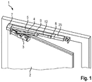
- Fig. 1 shows a locking assembly 1 according to the embodiment. Shown is a door 2. At this door 2, in addition to the locking assembly 1, a door operator 3, designed as a door closer, mounted. In the door operator 3, a closing spring is integrated. The force of the closing spring is transmitted from the closing spring via a linkage 4 to a sliding element 9. The sliding element 9 is guided in a slide rail 5 of the fixing arrangement 1 mounted on the side of the fall.
- the locking arrangement 1 comprises a danger detector 8. This is designed as a smoke detector and / or fire alarm.
- the danger detector 8 is connected to further signal transmitters 6, in particular further danger detectors (cf. FIG. 2 ) connectable, the signal generator 6 are mounted in particular on the ceiling.
- Another component of the Locking arrangement 1 is a holding device 7, with which the sliding element 9 can be detected.
- the holding device 7 is in the ascertaining state SZ. By fixing the sliding element 9, the door 2 is preserved in the open position.
- a control of the holding device 7 is carried out by and within two subsystems 25, their structure and function below with reference to FIG. 2 is described.
- the holding device 7 is controlled by the subsystems 25 in such a way that the sliding element 9 is detected, in particular, until the danger detector 8 emits a triggering signal to the subsystems 25.
- the hazard detector 8 In the case of smoke or fire, this is detected by the hazard detector 8 and / or by the external signalers 6.
- the external signal generator 6 are coupled via radio to the danger detector 8.
- the hazard detector 8 generates the trigger signal when a fire or smoke has been detected. This trigger signal is forwarded to the subsystems 25, whereby the holding device 7 releases the sliding member 9, wherein the holding device is transferred to the releasing state GZ.
- the energy pre-stored in the closing springs of the door operator 3 can close the door leaves of the door 2.
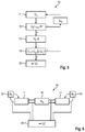
- FIG. 2 shows a schematic diagram of the Feststellan Aunt 1.
- two signal generator 6 are present, which communicate with the danger detector 8 via a radio link.
- the signal generator 6 are thus able to transmit a signal to the danger detector 8 when the signal transmitter 6 smoke or detect a fire.
- the danger detector 8 is designed to detect a fire.
- the locking assembly 1 has two subsystems 25, wherein the danger detector 8 is connected to the subsystems 25.
- the danger detector 8 is connected to two control devices 11.
- the control devices 11 have an identical function.
- the control devices 11 are in particular microcontrollers.
- the control devices 11 are connected to each other via a data line 20 for data exchange, so that a mutual monitoring of the control devices 11 is realized. This allows the detection of defects within one subsystem 25 by the other subsystem 25. Thus, redundancy is provided within the detent assembly 1.
- the control devices 11 are set up to control magnetic coils 10.
- Each subsystem 25 has at least one magnetic coil 10, so that each magnetic coil 10 of a subsystem 25 can be controlled by the control device 11 of the subsystem 25.
- the magnetic coils 10 are part of a holding device 7, with which an armature 22 is durable in at least two different positions, without having to be supplied from the outside energy.
- the holding device 7 has an electromagnet. The electromagnet holds the armature 22 in a first position until a current pulse on one of the magnetic coils 10 switches the electromagnet and thus converts the armature 22 into a second position different from the first position.
- the electromagnet holds the armature 22 in the second position until a current pulse on one of the magnetic coils 10 switches the electromagnet and transfers the armature 22 to the first position.
- the sliding element 9 and thus the door is detected, in the second position, the sliding element 9 is released.
- the energization of an electromagnet is sufficient to transfer the armature 22 in the positions.
- the magnetic coils 10 are redundant to each other.
- Each control device 11 is set up to apply a current pulse to a magnetic coil 10 in order to release the door 2.
- each control device 11 is connected in each case to a switch 16, electrical energy being output via the switches 16 in each case according to the specifications of the control devices 11 to a magnetic coil 10 assigned to the switch 16.
- Through the switch 16 can flow through the current through the solenoid 10 in different directions.
- the sliding element 9 is released.
- the locking assembly 1 is based on a working flow principle.
- the locking arrangement 1 in each subsystem 25 at least one measuring point 17, in particular for each magnetic coil 10 has its own measuring point 17 on.
- the measuring point 17 it is checked whether the magnetic coil 10 assigned switching signals are implemented and / or if there is an interruption of the circuit of the magnetic coil 10.
- the measuring point 17 of a subsystem 25 is electrically connected to the control device 11 of the subsystem 25. If a fault of the solenoid 10 of the subsystem 25 are detected, for example, an interruption in the circuit of the solenoid 10, so it is not guaranteed that a driving the solenoid 10, the slider 9 releases.
- a further magnetic coil 10 is present, so that the door 2 can be released by controlling the further magnetic coil 10.
- the control unit 11 checks whether the current intensity I 1 is within a predetermined value range.
- each subsystem has at least one energy buffer 15.
- the electrical energy required for operating the magnetic coils 10 is stored in each case in the intermediate energy storage 15, wherein in particular each magnetic coil 10 is associated with an energy buffer 15.
- the energy buffer 15 is electrically connected to the switch 16, so that the electrical energy stored in the energy buffer 15 can be delivered via the switch 16 to the solenoid coil 10.
- Each subsystem 25 also has at least one voltage converter 14, the intermediate energy storage devices 15 being charged via the voltage transformers 14, in particular each intermediate energy storage device 15, via a respective voltage converter 14, from a common energy storage unit 12.
- the energy storage unit 12 shown in three elements.
- the energy storage unit 12 is in particular a battery or an accumulator or a circuit of several batteries or accumulators.
- the locking assembly 1 is independent of an external power supply, such as a home network.
- Each subsystem 25 has at least one first voltage measuring point 13, wherein the energy storage unit 12 is connected to the control devices 11 via the first voltage measuring point 13.
- a voltage failure and / or an undervoltage of the energy storage unit 12 is detected. If a voltage value U 1 for the energy storage unit 12 is detected by means of the first voltage measuring point 13, which is below a predetermined voltage value U V1 and thus does not allow a reliable charging of the energy buffer 15, then one of the control devices 11 then controls the magnetic coil 10 such that the sliding member 9 is released. Thus, it is prevented that the sliding member 9 is held by the locking assembly 1 and due to a failure of the energy storage unit 12, a release is no longer possible.
- the locking arrangement 1 advantageously has a display device 18, with which the state of each magnetic coil 10 and / or the energy storage unit 12 can be displayed.
- the display device 18 may issue a warning if the voltage value U 1 determined by the first voltage measuring point 13 is below a threshold value U s .
- the threshold value U s is above the predetermined voltage value U V1 .
- a push button 19 is preferably provided.
- the control devices 11 initially prevent a renewed transfer of the holding device 7 into the ascertaining state SZ.
- the button 19 serves to enable the holding device 7 can be converted again into the determining state SZ.
- the locking arrangement 1 has a position sensor 23 which detects a position of the armature 22.
- the position sensor 23 is in particular a magnetic switch.
- a second voltage measuring point 26 is provided which determines electrical voltage values U 2 for the energy buffer 15.
- methods 30, 40, 50, 60 are shown, wherein all methods 30, 40, 50, 60 in the locking arrangement 1 according to the invention, in particular according to FIGS FIGS. 1 and 2 , are integrated.
- the methods 30, 40, 50, 60 are preferably stored in the control devices 11.
- the locking arrangement 1 can be formed in particular by means of the control devices 11, the methods 30, 40, 50, 60 perform.
- FIG. 3 a method 30 is shown in which a voltage value U 1 for the energy supply unit 12 is determined in a method step 31.
- the voltage value U 1 is compared with a stored in the control device 11 predetermined voltage value U V1 . If the voltage value U 1 is smaller than the voltage value U V1 , which is in FIG. 3 is represented by a "+", then in accordance with method step 33, the holding device 7 is transferred to the releasing state GZ. Without a change of the energy storage unit 12, it is not possible even by pressing the button 19, the holding device 7 back to the ascertaining state SZ.
- a warning W is issued in a method step 35.
- the determination of the voltage value U 1 and the subsequent routine is repeated at regular first time intervals ⁇ t 1 .
- FIG. 4 a method 40 is shown, in which the magnetic coil 10 is to be energized test half.
- the position of the armature 22 must first be determined in a method step 41 by the position sensor 23 and thereby determined whether the holding device 7 is in the ascertaining state SZ or in the releasing state GZ.
- the magnetic coil 10 is energized by the switch 16 in such a way that the current flowing through the magnetic coil 10 has no effect on the state of the holding device 7.
- the test T is performed for a predetermined discharge period ⁇ t 2 .
- the current intensity I 1 at the measuring point 17 is measured in a method step 43.
- the control unit 11 checks in a method step 44 whether the current intensity I 1 is in a value range I 0 , I 2 with I 0 ⁇ I 1 ⁇ I 2 . This is not the case, what is in FIG. 4 is marked with a "-", the holding device 7 is transferred to the releasing state GZ, which corresponds to the method step 45.
- the voltage value U 2 determined at the second voltage measuring point 26 is determined before and after the discharge time period ⁇ t 2 of the test T, and from this in a method step 46 a voltage value difference, ie a voltage drop ⁇ U 2, is calculated. Subsequently, it is checked in a method step 47 whether the voltage drop ⁇ U 2 is greater than a maximum value ⁇ U V. Is this the case, what is in FIG. 4 is marked with a "+", the holding device 7 is transferred to the releasing state GZ in accordance with method step 45. This prevents that in the case of an energy buffer 15, which has aged and can store only a small amount of electrical energy, in case of fire, the holding device 7 must be transferred to the releasing state GZ.
- FIG. 5 another method 50 is shown.
- the energy buffer 15 is determined according to the method step 51 at predetermined third time intervals .DELTA.t 5 within a voltage value U 2 for the intermediate energy storage 15.
- a method step 52 it is checked whether the determined voltage value U 2 falls below a setpoint voltage value U V2 by a predetermined amount B. If this is the case, what is in FIG. 5 is characterized by a "+”, it is trying to recharge the intermediate energy storage 15 according to the method step 53. This is not the case, what is in FIG. 5 is characterized by a "-", a new determination of U 2 is performed in the predetermined third time interval .DELTA.t 5 .
- the charging period .DELTA.t 4 has both an upper and a lower limit in the second range. Ie. the charge can be too slow z. B. because the voltage converter 14 is defective or too fast, z. B. because the energy buffer 15 has too little capacity.
- Charging does not occur in the charging period ⁇ t 4 , which is in FIG. 5 is marked with "-", the holding device 7 is transferred to the releasing state GZ in a method step 55. Otherwise, the routine is repeated in the predetermined third time intervals ⁇ t 5 .
- FIG. 6 a method 60 is shown, in which the control devices 11 monitor each other according to the method step 61 and each according to the respective method step 62. In this case, it is also checked in the method step 61 whether the control devices 11 leave an energy-saving mode.
- the holding device 7 is transferred by the other control device 11 in the releasing state GZ according to the method step 63. If no defect is detected, the method step 61 is repeated at monitoring time intervals ⁇ t 6 and the method step 62 is repeated at self-monitoring time intervals ⁇ t 7 .
Description
Die Erfindung betrifft eine Feststellanordnung für eine Tür, mit einer Haltevorrichtung zum Feststellen der Tür, insbesondere in einer offenen Stellung, wobei die Haltevorrichtung unter Zufuhr von elektrischer Energie von einem feststellenden Zustand in einen freigebenden Zustand überführbar ist, gemäß dem Oberbegriff des Patentanspruchs 1. Ferner betrifft die Erfindung ein Verfahren zum Betreiben einer Feststellanordnung.The invention relates to a locking arrangement for a door, with a holding device for locking the door, in particular in an open position, wherein the holding device is transferred under supply of electrical energy from a determining state to a releasing state, according to the preamble of
Feststellanordnungen sind in der Gebäudetechnik weit verbreitet für Tür- und Torsysteme, mit denen Brandschutzabschlüsse gemäß den geltenden Vorschriften ausgestattet werden. Die Feststellanordnung ermöglicht eine mit einem montierten Türschließer ausgerüstete Tür entweder in einem festgelegten oder gewählten Winkel offenzuhalten, bis sie elektrisch ausgelöst wird. In vorbekannten Lösungen werden die einzelnen Komponenten der Feststellanordnung mit dem Gebäudestromnetz zur Energieversorgung verbunden. Insbesondere bei der Nachrüstung oder Erweiterung bestehender Gebäude entsteht durch eine Verkabelung mit dem Gebäudestromnetz ein großer Aufwand. Um die Verkabelung optisch annehmbar zu verlegen, ist es gegebenenfalls notwendig, die Wände und Decken aufzustemmen, damit die Kabel "unter Putz" verlegt werden können. Im Falle historischer Gebäudesubstanzen entstehen dabei zum Teil erhebliche Schäden durch die Nachrüstung mit Feststellanordnungen für Feuerschutztüren.Locking arrangements are widely used in building services engineering for door and gate systems, which are equipped with fire barriers in accordance with the applicable regulations. The locking arrangement allows a door equipped with a mounted door closer to be kept open either at a fixed or selected angle until it is electrically triggered. In previously known solutions, the individual components of the locking arrangement are connected to the building power network for power supply. In particular, when retrofitting or expanding existing buildings is a great effort by wiring with the building electricity network. In order to make the wiring optically acceptable, it may be necessary to pry up the walls and ceilings so that the cables can be laid "under plaster". In the case of historic building substances, this sometimes causes considerable damage through the retrofitting with locking arrangements for fire doors.
Die
Der Erfindung liegt die Aufgabe zugrunde, eine Feststellanordnung und ein Verfahren zum Betreiben einer Feststellanordnung bereitzustellen, welche den vorgenannten Nachteil vermeidet, insbesondere eine Feststellanordnung und Verfahren bereitzustellen, die montagefreundlich sind.The invention has for its object to provide a locking arrangement and a method for operating a locking arrangement, which avoids the aforementioned disadvantage, in particular to provide a locking arrangement and methods that are easy to install.
Die Aufgabe wird gelöst durch den unabhängigen Anspruch 1. Vorteilhafte Weiterbildungen der Feststellanordnung sind in den abhängigen Vorrichtungsansprüchen, der Beschreibung und in den Figuren angegeben. Ferner wird die Erfindung auch durch die Merkmale des unabhängigen Verfahrensanspruchs gemäß dem unabhängigen Anspruch 11 gelöst. Vorteilhafte Weiterbildungen des Verfahrens sind in der Beschreibung und in den Figuren angegeben. Merkmale und Details, die in Zusammenhang mit der erfindungsgemäßen Feststellanordnung beschrieben sind, gelten dabei auch in Zusammenhang mit dem erfindungsgemäßen Verfahren und umgekehrt.The object is solved by the
Erfindungsgemäß ist vorgesehen, dass die Feststellanordnung dazu ausgebildet ist, die Haltevorrichtung von dem feststellenden Zustand in den freigebenden Zustand zu überführen, wenn ein Defekt bei der vorgesehenen Versorgung der Haltevorrichtung mit elektrischem Strom auftritt und/oder ein vorgegebener Spannungswert für eine Energiespeichereinheit, die zur Zufuhr von elektrischer Energie für die Haltevorrichtung dient, unterschritten wird.According to the invention, the locking arrangement is designed to transfer the retaining device from the locking state into the releasing state if a defect occurs in the intended supply of the retaining device with electric current and / or a predetermined voltage value for an energy storage unit which is responsible for the supply is used by electrical energy for the holding device, is exceeded.
Bei der erfindungsgemäßen Feststellanordnung ist das Arbeitsstromprinzip realisiert. Dabei ist vorgesehen, dass die Feststellanordnung ausgebildet ist, durch Zufuhr elektrischer Energie die Haltevorrichtung von einem feststellenden Zustand in einen freigebenden Zustand zu überführen. Insbesondere ist es möglich, dass sich die Haltevorrichtung ohne Zufuhr elektrischer Energie in dem feststellenden und/oder freigebenden Zustand befinden kann. Dies ermöglicht einen energiesparenden Betrieb der Feststellanordnung. Durch den energiesparenden Betrieb ist es möglich, auf eine Verkabelung zu dem Gebäudestromnetz zu verzichten und damit eine montagefreundliche Feststellanordnung bereitzustellen. Unter dem feststellenden Zustand der Haltevorrichtung wird insbesondere ein Zustand verstanden, der zum Feststellen der Tür durch die Haltevorrichtung dient. Unter dem freigebenden Zustand wird insbesondere ein Zustand verstanden, bei dem die Haltevorrichtung die Tür freigegeben hat, so dass die Tür bewegbar, insbesondere schließbar, ist. In dem freigebenden Zustand wird es insbesondere einem zusätzlich zu der Feststellanordnung vorhandenen Türbetätiger erlaubt, die Tür aus der zuvor gehaltenen Stellung zu schließen. Die Überführung der Haltevorrichtung von dem feststellenden in den freigebenden Zustand dient somit insbesondere zum Freigeben der Tür. Optional kann vorgesehen sein, dass durch Zufuhr von elektrischer Energie die Haltevorrichtung von dem freigebenden Zustand in den feststellenden Zustand überführbar ist.In the locking arrangement according to the invention, the working current principle is realized. It is provided that the locking arrangement is designed to transfer by supplying electrical energy, the holding device of a detecting state in a releasing state. In particular, it is possible that the holding device can be in the ascertaining and / or releasing state without the supply of electrical energy. This enables energy-saving operation of the locking arrangement. Due to the energy-saving operation, it is possible to dispense with a wiring to the building electricity network and thus provide a mounting-friendly Feststellanordnung. Under the determining state of the holding device is understood in particular a state that is for detecting the door is used by the holding device. Under the releasing state is understood in particular a state in which the holding device has released the door, so that the door is movable, in particular closable, is. In the releasing state, in particular, a door operator, in addition to the locking arrangement, is allowed to close the door from the previously held position. The transfer of the holding device from the determining to the releasing state thus serves in particular for releasing the door. Optionally, it can be provided that by supplying electrical energy, the holding device can be transferred from the releasing state into the ascertaining state.
Durch die erfindungsgemäße Ausgestaltung der Feststellanordnung wird die Haltevorrichtung immer dann in den freigebenden Zustand überführt, wenn eine Überführung zu einem späteren Zeitpunkt, insbesondere in einem Brandfall, nicht mehr sicher gewährleistet werden kann. Insbesondere erfolgt die Überführung in den freigebenden Zustand immer dann, wenn zuverlässig nur noch die Energie für eine vorgegebene Anzahl an Überführungen, insbesondere für eine Überführung, zur Verfügung steht und/oder wenn die Einleitung der Überführung in den freigebenden Zustand nicht mehr sicher gewährleistet ist. Unter einem Defekt bei der vorgesehenen Versorgung der Haltevorrichtung mit elektrischem Strom sind daher auch solche Defekte zu verstehen, die die Steuerung der Überführung betreffen.Due to the inventive design of the locking arrangement, the holding device is always transferred to the releasing state when a transfer at a later date, especially in a fire, can no longer be guaranteed safe. In particular, the transfer to the releasing state always takes place when only the energy for a predetermined number of transfers, in particular for transfer, is reliably available and / or when the initiation of the transfer into the releasing state is no longer reliably ensured. A defect in the intended supply of the holding device with electric current is therefore also to be understood as defects which relate to the control of the transfer.
Durch die erfindungsgemäße Feststellanordnung ist eine hohe Zuverlässigkeit der Freigabe erreicht, so dass die Tür im Falle einer Gefahr, insbesondere eines Brandes, sicher und zuverlässig freigegeben wird. Die Feststellvorrichtung ist besonders bevorzugt batteriebetrieben und damit unabhängig von einer externen Stromversorgung. Die Feststellanordnung ist insbesondere frei von einer elektrischen Verbindung zu einem Gebäudestromnetz.By locking arrangement according to the invention a high reliability of the release is achieved, so that the door in case of danger, especially a fire, is released safely and reliably. The locking device is particularly preferably battery operated and thus independent of an external power supply. The locking arrangement is in particular free of an electrical connection to a building electricity network.
Die Energiespeichereinheit kann einen oder mehrere elektrochemische Energiespeicher aufweisen. Der elektrochemische Energiespeicher kann als Batterie oder als Akkumulator ausgebildet sein. Die mehrere Energiespeicher können in Reihe und/oder parallel geschaltet sein. Beispielsweise können mehrere, z. B. zwei, Energiespeicher in Reihe und die Reihen der Energiespeicher zueinander wiederum parallel geschaltet sein. Insbesondere kann die Energiespeichereinheit als ein Energiespeicherpaket mit mehreren Energiespeichern ausgebildet sein.The energy storage unit may comprise one or more electrochemical energy stores. The electrochemical energy store can be designed as a battery or as an accumulator. The multiple energy storage can be connected in series and / or in parallel. For example, several, z. B. two, energy storage in series and the rows of energy storage each other in turn be connected in parallel. In particular, the energy storage unit may be formed as an energy storage package with multiple energy storage.
Die Feststellanordnung umfasst bevorzugt einen Gefahrendetektor, insbesondere einen Brand- und/oder Rauchmelder. Der Gefahrendetektor kann, insbesondere bei einem Brand, ein Auslösesignal an eine Steuervorrichtung der Feststellanordnung übermitteln. Hiernach steuert die Steuervorrichtung die Haltevorrichtung an, so dass die Haltevorrichtung von dem feststellenden in den freigebenden Zustand überführt wird.The locking arrangement preferably comprises a danger detector, in particular a fire and / or smoke detector. The danger detector can, in particular in the case of a fire, transmit a triggering signal to a control device of the locking arrangement. Thereafter, the control device controls the holding device, so that the holding device is transferred from the determining to the releasing state.
Die Feststellanordnung kann ein Gleitelement in einer Gleitschiene aufweisen. Bevorzugt ist durch die Haltevorrichtung das Gleitelement innerhalb einer Gleitschiene feststellbar und/oder freigebbar. Das heißt, bei einer Überführung der Haltevorrichtung von dem feststellenden in den freigebenden Zustand wird das Gleitelement freigegeben, so dass das Gleitelement in der Gleitschiene bewegbar wird. Das Gleitelement ist mit der Tür verbindbar. In dem feststellenden Zustand ist das Gleitelement in der Gleitschiene durch die Haltevorrichtung festgestellt. Bevorzugt blockiert die Haltevorrichtung, insbesondere eine Haltemechanik der Haltevorrichtung, das Gleitelement in der Gleitschiene in dem feststellenden Zustand. In dem freigebenden Zustand ist das Gleitelement in der Gleitschiene beweglich angeordnet, so dass auch die Tür bewegbar ist. Eine derartige Haltevorrichtung ist in der
Insbesondere ist die Haltevorrichtung dazu ausgebildet, die Tür in offener Stellung zu festzustellen. Entsprechend ist die Feststellanordnung bevorzugt dazu ausgebildet, bei Aussenden des Auslösesignals die Haltevorrichtung in den freigebenden Zustand zu überführen, so dass die Tür schließbar ist.In particular, the holding device is designed to determine the door in the open position. Accordingly, the locking arrangement is preferably designed to transmit the holding device in the releasing state when the trigger signal is emitted, so that the door can be closed.
Erfindungsgemäß weist die Feststellanordnung zumindest einen Energiezwischenspeicher, der insbesondere als zumindest ein Kondensatorelement ausgebildet ist, auf, in dem eine elektrische Energiemenge speicherbar ist, durch die die Haltevorrichtung von dem feststellenden Zustand in den freigebenden Zustand überführbar ist. Insbesondere ist durch die Energiemenge das Gleitelement freigebbar. Dadurch, dass ein Energiezwischenspeicher vorgesehen ist, kann auch bei einem Defekt der Energiespeichereinheit oder einer elektrischen Anschlussleitung der Energiespeichereinheit noch zumindest einmal die Haltevorrichtung in den freigebenden Zustand überführt werden. Durch den Einbau des Energiezwischenspeichers kann somit zur Zuverlässigkeit der nach dem Arbeitsstromprinzip arbeitenden Feststellanordnung beigetragen werden. Zudem kann es sein, dass nur der Energiezwischenspeicher eine genügende Stromstärke für die Magnetspule zur Verfügung stellen kann. Der empfohlene maximale Dauerstrom eines Energiespeichers der Energiespeichereinheit kann hingegen z. B. zwischen 20 mA und 200 mA, bevorzugt zwischen 60 mA und 120 mA betragen. Der maximale gepulste Entladestrom des Energiespeichers kann zwischen 80 mA und 400 mA, bevorzugt zwischen 150 mA und 250 mA betragen.According to the invention, the locking arrangement has at least one energy buffer, which is designed in particular as at least one capacitor element, in which an amount of electrical energy can be stored, by which the holding device can be transferred from the ascertaining state into the releasing state. In particular, the sliding element can be released by the amount of energy. Characterized in that an energy buffer is provided, even in the case of a defect of the energy storage unit or an electrical connection line of the energy storage unit, the holding device can be transferred to the releasing state at least once. The installation of the intermediate energy store can thus contribute to the reliability of the locking arrangement operating on the working current principle. In addition, it may be that only the intermediate energy storage can provide a sufficient current for the solenoid. The recommended maximum continuous current of an energy storage of the energy storage unit, however, z. B. between 20 mA and 200 mA, preferably between 60 mA and 120 mA. The maximum pulsed discharge current of the energy store can be between 80 mA and 400 mA, preferably between 150 mA and 250 mA.
Bevorzugt ist zumindest die zweifache Energiemenge, die zur Überführung der Haltevorrichtung notwendig ist, in dem Energiezwischenspeicher speicherbar. Der Energiezwischenspeicher ist insbesondere elektrisch zwischen der Energiespeichereinheit und der Haltevorrichtung geschaltet. Besonders bevorzugt ist die Energiemenge der Energiespeichereinheit nur über dem Energiezwischenspeicher der Haltevorrichtung zuführbar. Der Energiezwischenspeicher kann insbesondere nur aus der Energiespeichereinheit aufladbar sein.Preferably, at least twice the amount of energy that is necessary for transferring the holding device can be stored in the intermediate energy store. The energy buffer is in particular electrically connected between the energy storage unit and the holding device. Particularly preferably, the amount of energy of the energy storage unit can be supplied only via the energy buffer of the holding device. The Energy buffer can be rechargeable in particular only from the energy storage unit.
Die Steuervorrichtung, insbesondere ein Mikrocontroller, kann insbesondere dazu ausgebildet sein, zu initiieren, dass die Haltevorrichtung von dem feststellenden in den freigebenden Zustand überführt wird, wenn ein Defekt bei der vorgesehenen Versorgung der Haltevorrichtung mit elektrischem Strom auftritt und/oder der vorgegebenen Spannungswert unterschritten wird. Hierbei kann die Steuervorrichtung insbesondere den Defekt und/oder die Unterschreitung des vorgegebenen Spannungswerts detektieren.The control device, in particular a microcontroller, can in particular be designed to initiate that the holding device is transferred from the determining to the releasing state if a defect occurs in the intended supply of the holding device with electric current and / or the predetermined voltage value is undershot , In this case, the control device can in particular detect the defect and / or the undershooting of the predetermined voltage value.
Erfindungsgemäß ist eine erste Spannungsmessstelle zum Ermitteln eines die elektrische Spannung der Energiespeichereinheit charakterisierenden Spannungswertes vorgesehen. Bei einem durch die erste Spannungsmessstelle ermittelten Spannungswert unterhalb des vorgegebenen Spannungswertes wird die Haltevorrichtung in den freigebenden Zustand überführt. Die erste Spannungsmessstelle kann elektrisch parallel zu der Energiespeichereinheit und der Steuervorrichtung geschaltet sein. Der vorgegebene Spannungswert kann insbesondere ein an der ersten Spannungsmessstelle ermittelbarer, die vorgegebene Spannung der Energiespeichereinheit charakterisierender Spannungswert sein. Die Spannungsmessung kann in ersten vorgegebenen Zeitabständen durchgeführt werden. Die ersten vorgegebenen Zeitabstände können in der Steuervorrichtung hinterlegt sein. Die Steuervorrichtung kann die Spannungsmessung durchführen. Hierbei kann an der ersten Spannungsmessstelle z. B. ein Spannungsteiler vorgesehen sein. Alternativ oder zusätzlich kann die erste Spannungsmessstelle einen Spannungsmesser aufweisen, der den ermittelten Spannungswert an die Steuereinheit übermittelt. Die Steuereinheit vergleicht den ermittelten mit dem vorgegebenen Spannungswert und lässt gegebenenfalls die Haltevorrichtung in den freigebenden Zustand überführen. Der vorgegebene Spannungswert kann in der Steuervorrichtung hinterlegt sein. Oberhalb des vorgegebenen Spannungswerts kann ein vorgegebener Schwellenwert für einen durch die erste Spannungsmessstelle ermittelten Spannungswert vorgesehen sein, bei dem eine Warnung herausgegeben wird. Als Warnung kann beispielsweise ein Leuchtelement der Feststellanordnung leuchten. Hierbei kann das Leuchtelement z. B. blinken. Durch die Warnung wird eine Bedienperson darauf hingewiesen, dass die Energiespeichereinheit demnächst auszutauschen ist.According to the invention, a first voltage measuring point is provided for determining a voltage value characterizing the electrical voltage of the energy storage unit. At a voltage value determined by the first voltage measuring point below the predetermined voltage value, the holding device is transferred to the releasing state. The first voltage measuring point can be connected electrically in parallel to the energy storage unit and the control device. The predefined voltage value may in particular be a voltage value that can be determined at the first voltage measuring point and that characterizes the predefined voltage of the energy storage unit. The voltage measurement can be carried out at first predetermined time intervals. The first predetermined time intervals can be stored in the control device. The control device can perform the voltage measurement. Here, at the first voltage measuring point z. B. a voltage divider may be provided. Alternatively or additionally, the first voltage measuring point may have a voltmeter which transmits the determined voltage value to the control unit. The control unit compares the determined with the predetermined voltage value and can optionally transfer the holding device in the releasing state. The predetermined voltage value can be stored in the control device. Above the predetermined voltage value, a predetermined threshold value can be provided for a voltage value determined by the first voltage measuring point, in which case a Warning is issued. As a warning, for example, a lighting element of the locking arrangement can shine. Here, the light element z. B. flashing. The warning informs an operator that the energy storage unit is about to be replaced.
Der einzelne elektrochemische Energiespeicher kann mindestens ein Verhältnis V1 der Nominalspannung zu einem empfohlenen maximalen Dauerstrom von 10 Ω ≤ V1 ≤ 40 Ω, bevorzugt 15 Ω ≤ V1 ≤ 30 Ω aufweisen. Zusätzlich oder alternativ kann der einzelne Energiespeicher ein Verhältnis V2 der Nominalspannung zu einem maximalen gepulsten Entladungsstrom von 20 Ω ≤ V2 ≤ 100 Ω, bevorzugt 30 Ω ≤ V2 ≤ 70 Ω aufweisen. Hierdurch ist eine kritische Erwärmung des Energiespeichers ausgeschlossen. Zusätzlich oder alternativ kann in der Energiespeichereinheit eine Sicherung vorgesehen sein. Hierdurch kann somit zur Zuverlässigkeit der nach dem Arbeitsstromprinzip arbeitenden Feststellanordnung beigetragen werden.The individual electrochemical energy store can have at least a ratio V1 of the nominal voltage to a recommended maximum continuous current of 10 Ω ≤ V1 ≤ 40 Ω, preferably 15 Ω ≤ V1 ≤ 30 Ω. Additionally or alternatively, the individual energy store may have a ratio V2 of the nominal voltage to a maximum pulsed discharge current of 20 Ω ≤ V2 ≤ 100 Ω, preferably 30 Ω ≤ V2 ≤ 70 Ω. As a result, a critical heating of the energy storage is excluded. Additionally or alternatively, a fuse may be provided in the energy storage unit. In this way, it is thus possible to contribute to the reliability of the locking arrangement operating on the working current principle.
Bevorzugt liegt ein Defekt bei der vorgesehenen Versorgung der Haltevorrichtung mit elektrischem Strom vor, wenn ein Kurzschluss und/oder eine Unterbrechung innerhalb der Energiespeichereinheit und/oder in der Anschlussleitung der Energiespeichereinheit erfolgt. Somit wird die Haltevorrichtung von dem feststellenden in den freigebenden Zustand überführt. Hierbei kann der Energiezwischenspeicher die elektrische Energie zur Verfügung stellen. Der Kurzschluss oder die Unterbrechung kann durch den an der ersten Spannungsmessstelle ermittelten Spannungswert erfolgen, der unter dem vorgegebenen Spannungswert liegt.A defect in the intended supply of the holding device with electrical current is preferably present when there is a short circuit and / or an interruption within the energy storage unit and / or in the connection line of the energy storage unit. Thus, the holding device is transferred from the determining to the releasing state. In this case, the energy buffer store can provide the electrical energy. The short circuit or the interruption can be effected by the voltage value determined at the first voltage measuring point, which is below the predetermined voltage value.
Es kann vorgesehen sein, dass die Haltevorrichtung eine elektrisch durchfließbare Komponente aufweist. Mit der Hilfe der elektrisch durchfließbaren Komponente kann der freigebende Zustand erreicht werden. Die elektrisch durchfließbare Komponente kann z. B. als eine Magnetspule ausgebildet sein. Durch die Komponente ist ein Element der Haltevorrichtung, z. B. ein Anker, bewegbar, durch das die Überführung in den freigebenden Zustand erfolgt. Beispielsweise kann hierbei eine Blockade einer Haltemechanik der Haltevorrichtung aufgehoben werden. Die Komponente kann hierbei Teil eines Aktors, z. B. eines Elektromagneten oder eines Elektromotors, sein. Die elektrisch durchfließbare Komponente kann insbesondere mit elektrischen Strom mit unterschiedlichen Stromrichtungen durchfließbar sein. Die hierdurch erzeugten Magnetfelder können das Element zwischen zwei Positionen bewegen, die dem feststellenden Zustand und dem freigebenden Zustand entsprechen. Hierzu wird erneut auf die
Die Feststellanordnung kann eine Messstelle zur Ermittlung einer elektrischen Stromstärke, der durch die elektrisch durchfließbare Komponente fließt, aufweisen, wobei ein Defekt bei der vorgesehenen Versorgung der Haltevorrichtung mit elektrischem Strom vorliegt, wenn die ermittelte Stromstärke außerhalb eines vorgegebenen Wertebereichs liegt. Die Steuervorrichtung kann die Stromstärke ermitteln. Hierbei kann an der Messstelle ein Widerstand vorgesehen sein. Insbesondere wird über einer Messung einer am Widerstand anliegenden Spannung die Stromstärke ermittelt. Alternativ oder zusätzlich kann die Strommessstelle einen Strommesser aufweisen, der die gemessenen Stromstärke an die Steuereinheit übermittelt. Die Steuereinheit überprüft, ob die gemessene Stromstärke innerhalb des vorgegebenen Wertebereichs liegt und lässt, falls nicht, die Haltevorrichtung in den freigebenden Zustand überführen. Eine obere Grenze des Wertebereichs kann z. B. dazu dienen, einen Kurzschluss festzustellen. Eine untere Grenze des Wertebereichs kann z. B. dazu dienen, festzustellen, ob eine Unterbrechung des Stromkreises vorliegt und/oder ob eine genügende Stromstärke zur Erzeugung eines ausreichenden Magnetfelds zur Überführung der Haltevorrichtung in den freigebenden Zustand vorliegt.The locking arrangement can have a measuring point for determining an electrical current flowing through the component which can flow electrically, wherein there is a defect in the intended supply of the holding device with electric current if the determined current strength is outside a predetermined value range. The control device can determine the current intensity. In this case, a resistor may be provided at the measuring point. In particular, the current intensity is determined via a measurement of a voltage applied to the resistor. Alternatively or additionally, the current measuring point can have an ammeter which transmits the measured current intensity to the control unit. The control unit checks whether the measured current strength is within the predetermined value range and, if not, allows the holding device to be released. An upper limit of the value range may, for. B. serve to detect a short circuit. A lower limit of the value range can, for. B. serve to determine if there is an interruption of the circuit and / or if there is a sufficient current to generate a sufficient magnetic field for the transfer of the holding device in the releasing state.
Die Ermittlung der Stromstärke kann in zweiten vorgegebenen Zeitabständen durchgeführt werden. Somit kann die Ermittlung der Stromstärke auch nur testhalber durchgeführt werden. Daher kann die Ermittlung der Stromstärke auch dann erfolgen, wenn keine Überführung in den freigebenden oder den feststellenden Zustand erfolgen soll. Die zweiten vorgegebenen Zeitabstände können in der Steuervorrichtung hinterlegt sein. Die zweiten vorgegebenen Zeitabstände können insbesondere identisch sein. So kann beispielsweise alle vierundzwanzig Stunden eine derartige Messung durchgeführt werden. Damit durch den Stromfluss durch die elektrisch durchfließbare Komponente bei einem Test keine Überführung in den freigebenden Zustand erfolgt, kann vorgesehen sein, dass zur Durchführung der Messung, die testhalber durchgeführt wird, die elektrisch durchfließbare Komponente mit einer derartigen Polung bestromt wird, dass die Bestromung wirkungslos auf den Zustand der Haltevorrichtung ist. Zusätzlich oder alternativ wird die Stromstärke bei einer durch das Auslösesignal ausgelösten Überführung in den freigebenden Zustand ermittelt.The determination of the current intensity can be carried out at second predetermined time intervals. Thus, the determination of the current can be carried out only for test purposes. Therefore, the determination of the current can also take place when no transfer to the releasing or the determining state should take place. The second predetermined time intervals can be stored in the control device. The second predetermined time intervals can be identical in particular. For example, such a measurement may be performed every twenty four hours. So that the current flow through the component which can flow through electrically does not lead to a release into the releasing state, it can be provided that the electrically flowable component is energized with such a polarity to carry out the measurement, which is carried out for testing purposes, that the current supply is ineffective on the state of the holding device is. Additionally or alternatively, the current intensity is determined at a triggered by the trigger signal transfer to the releasing state.
Die Energiespeichereinheit kann über einen Spannungswandler mit dem Energiezwischenspeicher verbunden. Über den Spannungswandler kann eine höhere elektrische Spannung in dem Energiezwischenspeicher als in dem Energiespeichereinheit erzeugt werden. Insbesondere über den Spannungswandler kann die Steuervorrichtung ein Aufladen des Energiezwischenspeichers veranlassen.The energy storage unit can be connected via a voltage converter to the energy buffer. Via the voltage converter, a higher electrical voltage can be generated in the energy buffer than in the energy storage unit. In particular, via the voltage converter, the control device can cause a charging of the energy buffer.
Erfindungsgemäß ist eine zweite Spannungsmessstelle zur Ermittlung eines die elektrischen Spannung des Energiezwischenspeichers charakterisierenden Spannungswerts vorgesehen. Die zweite Spannungsmessstelle kann elektrisch parallel zu dem Energiezwischenspeicher und der Steuervorrichtung geschaltet sein. Die Spannungsmessung an der zweiten Spannungsmessstelle kann in vorgegebenen dritten Zeitabständen durchgeführt werden. Die dritten vorgegebenen Zeitabstände können in der Steuervorrichtung hinterlegt sein. Die Steuervorrichtung kann die Spannungsmessung an der zweiten Spannungsmessstelle durchführen. Hierbei kann an der zweiten Spannungsmessstelle ein Spannungsteiler vorgesehen sein. Alternativ oder zusätzlich kann die zweite Spannungsmessstelle einen Spannungsmesser aufweisen, der den gemessenen Spannungswert an die Steuereinheit übermittelt.According to the invention, a second voltage measuring point is provided for determining a voltage value characterizing the electrical voltage of the intermediate energy store. The second voltage measuring point can be electrically connected in parallel to the energy buffer and the control device. The voltage measurement at the second voltage measuring point can be carried out at predetermined third time intervals. The third predetermined time intervals can be stored in the control device. The control device may perform the voltage measurement at the second voltage measurement point. In this case, a voltage divider may be provided at the second voltage measuring point. Alternatively or additionally, the second voltage measuring point can have a voltmeter which transmits the measured voltage value to the control unit.
Bevorzugt wird der den Energiezwischenspeicher charakterisierenden Spannungswert, der an der zweiten Spannungsmessstelle ermittelt wurde, mit einem Sollspannungswert verglichen. Unterschreitet der Spannungswert den Sollspannungswert um einen vorgegebenen Betrag, so wird insbesondere durch die Steuervorrichtung veranlasst, dass der Energiezwischenspeicher auf den Sollspannungswert aufgeladen wird. Der Sollspannungswert kann in der Steuereinheit hinterlegt sein. Die vorgegebenen Zeitabstände können insbesondere identisch sein. Hierdurch wird sichergestellt, dass der Energiezwischenspeicher eine genügende Energiemenge zur Überführung der Haltevorrichtung in den freigebenden Zustand gespeichert hat und sich nicht über die Zeit zu weit entladen hat.The voltage value characterizing the intermediate energy storage device, which was determined at the second voltage measurement point, is preferably compared with a nominal voltage value. If the voltage value falls below the setpoint voltage value by a predetermined amount, in particular the control device causes the energy buffer to be charged to the setpoint voltage value. The nominal voltage value can be stored in the control unit. The predetermined time intervals can be identical in particular. This ensures that the energy buffer has stored a sufficient amount of energy to transfer the holding device in the releasing state and has not over-discharged over time.
Bevorzugt liegt ein Defekt bei der vorgesehenen Versorgung der Haltevorrichtung mit elektrischem Strom vor, wenn eine Aufladung des Energiezwischenspeichers auf eine Sollspannungswert innerhalb einer vorgegebenen Ladezeitspanne scheitert. Hierzu kann insbesondere die Steuereinheit überprüfen, ob der Energiezwischenspeicher innerhalb der vorgegebenen Ladezeitspanne den Sollspannungswert erreicht. Wird innerhalb der Ladezeitspanne der Sollspannungswert nicht erreicht, so liegt ein Defekt bei der vorgesehenen Versorgung der Haltevorrichtung mit elektrischer Energie vor. In diesem Fall wird die Haltevorrichtung in den freigebenden Zustand überführt. Beispielsweise kann ein Kurzschluss in dem Energiezwischenspeicher vorliegen oder der Spannungswandler defekt sein. Ebenfalls kann der Energiezwischenspeicher gealtert sein und eine geringe Kapazität aufweisen, so dass die Aufladung auf den Sollspannungswert zu schnell erfolgt.Preferably, there is a defect in the intended supply of the holding device with electric current, if a charging of the intermediate energy storage fails to a target voltage value within a predetermined charging period. For this purpose, in particular, the control unit can check whether the energy buffer reaches the target voltage value within the predetermined charging period. If the target voltage value is not reached within the charging period, there is a defect in the intended supply of the holding device with electrical energy. In this case, the holding device is transferred to the releasing state. For example, there may be a short circuit in the energy buffer or the voltage converter may be defective. Also, the energy buffer may be aged and have a small capacity, so that the charge on the target voltage value is too fast.
Die vorgegebene Ladezeitspanne Δt4 kann damit durch einen oberen Grenzwert toben und einen unteren Grenzwert tunten größer Null begrenzt sein. Hierbei können tunten und toben in Abhängigkeit von dem zu unterschreitenden Betrag und der Kapazität des Kondensatorelements gewählt sein. Als ein Wert kann tunten z. B. zwischen 0,1 s und 10 s, bevorzugt zwischen 1 s und 4 s gewählt sein. Als ein Wert kann toben z. B. zwischen 10 s und 60 s, bevorzugt zwischen 5 s und 30 s gewählt sein. Beispielsweise kann die Ladezeitspanne Δt4 gegeben sein durch 0,1 s=tunten ≤ Δt4 ≤ 60 s=toben oder 1 s=tunten ≤ Δt4 ≤ 30 s=toben oder 3 s = tunten ≤ Δt4 ≤ 16 s=toben. Insbesondere wird durch die untere Grenze tunten einer Alterung des Energiezwischenspeichers, z. B. um 10 % bis 50 %, bevorzugt um 20% bis 40%, Rechnung getragen.The predefined charging time interval Δt 4 can thus be limited by an upper limit value t above and a lower limit value t below greater than zero. In this case, t can be selected below and t above depending on the amount to be undershot and the capacitance of the capacitor element. As a value, t below z. B. between 0.1 s and 10 s, preferably between 1 s and 4 s. As a value, t can be stored at the top of z. B. between 10 s and 60 s, preferably between 5 s and 30 s be selected. For example, the charging period Δt 4 may be given by 0.1 s = t down ≤ Δt 4 ≤ 60 s = t above or 1 s = t down ≤ Δt 4 ≤ 30 s = t above or 3 s = t down ≤ Δt 4 ≤ 16 s = t above . In particular, by the lower limit t below an aging of the energy buffer, z. B. by 10% to 50%, preferably by 20% to 40%, taken into account.
Es ist denkbar, dass ein Defekt bei der vorgesehenen Versorgung der Haltevorrichtung mit elektrischer Energie vorliegt, wenn ein an der zweiten Spannungsmessstelle ermittelter Spannungsabfall bei einer Entladung des Energiezwischenspeichers für eine vorgegebene Entladezeitspanne größer als ein vorgegebener Maximalwert ist. Durch eine Alterung des Energiezwischenspeichers kann der Energiezwischenspeicher an Kapazität verlieren. Ebenfalls ist es denkbar, dass der Energiezwischenspeicher bei unterschiedlichen Temperaturen unterschiedliche Kapazitäten inne hat. Bei einer geringeren Kapazität ist jedoch bei einer vorgegebenen Spannung eine geringere Ladungsmenge in dem Energiezwischenspeicher gespeichert. Um zu verhindern, dass die gespeicherte Ladungsmenge für eine Überführung der Haltevorrichtung in den freigebenden Zustand nicht ausreicht, wird der Spannungsabfall bei einer Entladung des Energiezwischenspeichers für die vorgegebene Entladezeitspanne überprüft, der ein Indikator für die gespeicherte Ladungsmenge und damit für die Kapazität des Energiezwischenspeichers ist.It is conceivable that there is a defect in the intended supply of the holding device with electrical energy, if a voltage drop determined at the second voltage measuring point is greater than a predefined maximum value for a discharge of the intermediate energy storage device for a predetermined discharge period. Due to aging of the energy buffer, the energy buffer can lose capacity. It is also conceivable that the energy buffer has different capacities at different temperatures. At a lower capacity, however, a smaller amount of charge is stored in the intermediate energy storage at a given voltage. In order to prevent the stored amount of charge from being insufficient for a transfer of the holding device into the releasing state, the voltage drop is checked during a discharge of the energy buffer for the predetermined discharge period, which is an indicator for the stored charge quantity and thus for the capacity of the energy buffer.
Der Maximalwert für den Spannungsabfall und/oder die Entladezeitspanne können in der Steuervorrichtung hinterlegt sein. Der Vergleich zwischen dem Maximalwert und dem ermittelten Spannungsabfall kann durch die Steuervorrichtung erfolgen.The maximum value for the voltage drop and / or the discharge period can be stored in the control device. The comparison between the maximum value and the determined voltage drop can be made by the control device.
Bevorzugt wird der Energiezwischenspeicher zur Ermittlung des Spannungsabfalls in der Entladezeitspanne entladen, indem der zuvor beschriebene Test durchgeführt wird, bei dem die elektrisch durchfließbare Komponente mit einer derartigen Polung bestromt wird, dass die Bestromung wirkungslos auf den Zustand der Haltevorrichtung ist. Somit können in einem Vorgang sowohl der Stromfluss durch die elektrisch durchfließbare Komponente als auch die Kapazität des Energiezwischenspeichers überpüft werden.The energy buffer is preferably discharged for determining the voltage drop in the discharge period by carrying out the test described above, in which the component which can flow through electrically is energized with such a polarity that the current supply is ineffective on the state of the holder. Thus, both the current flow through the electrically flowable component and the capacity of the energy buffer can be overhauled in one operation.
Es kann sein, dass die Feststellanordnung zumindest zwei zueinander redundante Energiezwischenspeicher und/oder zumindest zwei zueinander redundante elektrisch durchfließbare Komponenten aufweist. Somit kann bei einem Defekt eines Energiezwischenspeichers oder einer elektrisch durchfließbaren Komponente die Überführung der Haltevorrichtung in die freigebende Stellung zuverlässig bewirkt werden. Hierdurch ist es möglich, dass bei einem schwerwiegenden Defekt des Energiezwischenspeichers und/oder der elektrisch durchfließbaren Komponente durch den redundanten Energiezwischenspeicher und/oder die redundante elektrisch durchfließbare Komponente die Haltevorrichtung dennoch in den freigebenden Zustand überführbar ist. Der schwerwiegende Defekt kann z. B. ein Kurzschluss in dem Energiezwischenspeicher sein. Jede elektrisch durchfließbare Komponente ist dabei derart ausgestaltet, dass ohne die Hilfe der weiteren elektrisch durchfließbare Komponente der freigebende Zustand herbeigeführt werden kann.It may be that the locking arrangement has at least two mutually redundant energy buffers and / or at least two mutually redundant electrically flowable components. Thus, in case of a defect of an energy buffer or an electrically flowable component, the transfer of the holding device can be reliably effected in the releasing position. This makes it possible that in a serious defect of the intermediate energy storage and / or the electrically flowable component by the redundant energy buffer and / or the redundant electrically flowable component, the holding device can still be transferred to the releasing state. The serious defect can z. B. be a short circuit in the energy buffer. Each electrically flowable component is designed such that without the help of further electrically flowable component of the releasing state can be brought about.
Bevorzugt sind zumindest zwei Subsysteme vorgesehen, die jeweils zumindest einen Energiezwischenspeicher und eine elektrisch durchfließbare Komponente umfassen, wobei die Subsysteme jeweils unabhängig voneinander ausgestaltet sind. Die Subsysteme sind insbesondere redundant zueinander.Preferably, at least two subsystems are provided, each comprising at least one energy buffer and an electrically flowable component, wherein the subsystems are each configured independently of each other. The subsystems are in particular redundant to each other.
Es kann vorgesehen sein, dass die Feststellanordnung zumindest zwei Steuervorrichtungen aufweist, die sich gegenseitig überwachen, wobei ein Defekt bei der vorgesehenen Versorgung der Haltevorrichtung mit elektrischem Strom vorliegt, wenn eine Steuervorrichtung fehlerhaft ist. Beispielsweise kann bei einem Ausbleiben eines cyclischen Triggersignals eine der Steuervorrichtungen einen Defekt bei der anderen Steuervorrichtung feststellen und die Überführung der Haltevorrichtung in den freigebenden Zustand veranlassen. Die Steuervorrichtungen können sich in vorgegebenen Überwachungszeitabständen, die insbesondere in den Steuervorrichtungen hinterlegt sind, überwachen. Ferner kann vorgesehen sein, dass die Steuervorrichtungen sich selber überwachen. Hierzu können beispielsweise CPU und RAM-Test durchgeführt werden. Insbesondere wird die Selbstüberwachung in regelmäßigen, vorgegebenen Selbstüberwachungsabständen durchgeführt. Wird bei einer Überwachung ein Fehler, z. B. beim CPU- oder RAM-Test festgestellt, so wird ein Defekt bei der vorgesehen Versorgung der Haltevorrichtung mit elektrischem Strom detektiert und die Haltevorrichtung insbesondere durch die weitere intakte Steuervorrichtung in den freigebenden Zustand überführt.It can be provided that the locking arrangement has at least two control devices which monitor each other, wherein there is a defect in the intended supply of the holding device with electric current, if a control device is faulty. For example, in the absence of a cyclic trigger signal, one of the control devices can detect a defect in the other control device and cause the transfer of the holding device in the releasing state. The control devices can monitor at predetermined monitoring intervals, which are stored in particular in the control devices. Furthermore, it can be provided that the control devices monitor themselves. For this example, CPU and RAM test can be performed. In particular, self-monitoring is performed at regular, predetermined self-monitoring intervals. Is activated during monitoring Error, z. B. detected in the CPU or RAM test, a defect in the provided supply of the holding device is detected with electric current and transferred the holding device in particular by the further intact control device in the releasing state.
Die zumindest zwei Steuervorrichtungen können jeweils Teil eines Subsystems sein. Somit kann jedes Subsystem von einem Empfang eines Auslösesignals bis zur elektrisch durchfließbaren Komponente der Haltevorrichtung reichen. Hierbei kann durch jedes der Subsysteme die Haltevorrichtung unabhängig von dem anderen Subsystem in den freigebenden Zustand überführt werden.The at least two control devices can each be part of a subsystem. Thus, each subsystem may range from receiving a trigger signal to the electrically flowable component of the fixture. Here, by each of the subsystems, the holding device can be transferred independently of the other subsystem in the releasing state.
Bevorzugt liegt ein Defekt bei der vorgesehen Versorgung der Haltevorrichtung mit elektrischem Strom vor, wenn das Verlassen eines Energiesparmodus der Steuervorrichtung ausbleibt. In einem Zeitraum, in der die Steuervorrichtung keine Überwachung und keine Überführung in den freigebenden Zustand vornehmen muss, kann sich die Steuervorrichtung in einem Energiesparmodus befinden. Kann die Steuervorrichtung den Energiesparmodus nicht verlassen, so wird die Haltevorrichtung in den freigebenden Zustand überführt. Dieser Defekt kann insbesondere durch eine andere Steuervorrichtung detektiert werden.Preferably, there is a defect in the intended supply of the holding device with electric current when leaving a power saving mode of the control device is missing. In a period in which the control device does not need to monitor and transfer to the releasing state, the control device may be in a power saving mode. If the control device can not leave the energy saving mode, then the holding device is transferred to the releasing state. This defect can be detected in particular by another control device.
Es ist denkbar, dass ein Taster vorgesehen ist, um nach einer Überführung in den freigebenden Zustand, insbesondere nach einem Empfang eines Brandmeldesignals und/oder einem Wechsel der Energiespeichereinheit, eine erneute Anordnung der Haltevorrichtung in den feststellenden Zustand zu ermöglichen. Ebenfalls kann es sein, dass nach Behebung eines Defekts, insbesondere eines Kurzschlusses z. B. im Energiezwischenspeicher oder in der Energiespeichereinheit, durch Betätigung des Tasters und einem Selbsttest eine erneute Überführung in den feststellenden Zustand ermöglicht sein kann. Alternativ kann vorgesehen sein, dass bei einer Betätigung des Tasters nur in eine erneute Überführung der Haltevorrichtung in den feststellenden Zustand möglich ist, wenn ein Brandmeldesignal empfangen wurde und/oder wenn ein cyclisches Gefahrendetektorsignal ausbleibt und/oder wenn die Energiespeichereinheit ausgewechselt wurde.It is conceivable that a push-button is provided in order to allow a re-arrangement of the holding device in the determining state after a transfer to the releasing state, in particular after receiving a fire alarm signal and / or a change of the energy storage unit. It may also be that after remedying a defect, in particular a short circuit z. B. in the energy buffer or in the energy storage unit, by pressing the button and a self-test re-transfer to the determining state may be possible. Alternatively it can be provided that upon actuation of the button only in a renewed transfer of the holding device in the ascertaining state is possible if a fire alarm signal was received and / or if a cyclic danger detector signal is missing and / or if the energy storage unit has been replaced.
Vorzugsweise ist vorgesehen, dass nach einem bestimmten Defekt und/oder nach Unterschreiten des vorgegebenen Spannungswertes vor Wechsel der Energiespeichereinheit die Haltevorrichtung in dem freigebenden Zustand verharrt. D. h. ein Versuch, die Tür erneut in geöffneter Stellung festzustellen, scheitert. Hierbei kann insbesondere bei einer Betätigung des Tasters eine erneute Überführung der Haltevorrichtung in den feststellenden Zustand verhindert sein. Hierzu kann insbesondere eine Bestromung der elektrisch durchfließbaren Komponente in einer Stromrichtung, die den feststellenden Zustand hervorruft, verhindert sein. Ein Defekt, bei dem die Haltevorrichtung in dem freigebenden Zustand verharrt, kann zumindest einer der folgenden Defekte sein:
- Bei einem Kurzschluss in der Anschlussleitung der Energiespeichereinheit und/oder in dem Energiezwischenspeicher bei einer Beschädigung weitere Bauteile. Hierbei kann die Beschädigung durch einen Selbsttest ermittelt werden,
- Bei dem an der zweiten Spannungsmessstelle ermittelter Spannungsabfall bei einer Entladung des Energiezwischenspeichers für eine vorgegebene Entladezeitspanne, der größer als ein vorgegebener Maximalwert ist,
- Bei einem Unterschreiten der an der ersten Spannungsmessstelle ermittelten Spannungswerts für die Energiespeichereinheit unter den vorgegebenen Spannungswert bevor einem Wechsel der Energiespeichereinheit,
- bei einer an der Messstelle ermittelten Stromstärke außerhalb des vorgegebenen Wertebereichs,
- bei einer Aufladung des Energiezwischenspeichers auf eine Sollladespannung außerhalb der vorgegebenen Ladezeitspanne,
- bei einer defekten Steuervorrichtung.
- In the event of a short circuit in the connecting line of the energy storage unit and / or in the energy buffer store in the event of damage, further components. In this case, the damage can be determined by a self-test,
- At the voltage drop determined at the second voltage measuring point during a discharge of the intermediate energy storage device for a predefined discharge time period that is greater than a predefined maximum value,
- If the voltage value for the energy storage unit determined at the first voltage measuring point falls below the predetermined voltage value before a change of the energy storage unit,
- at a current at the measuring point outside the specified value range,
- when charging the energy buffer to a desired charging voltage outside the predetermined charging period,
- with a defective control device.
Es kann sein, dass ein Kondensator vorgesehen ist, um bei Ausfall der Energieversorgungseinheit die Steuervorrichtung mit elektrischer Energie zu versorgen. Im Falle redundanter Steuervorrichtungen ist insbesondere jeder Steuervorrichtung ein Kondensator zugeordnet. Insbesondere ist in dem Kondensator zumindest die Energiemenge speicherbar, die notwendig ist, damit die Steuervorrichtung die Überführung der Haltevorrichtung in den freigebenden Zustand initiiert.It may be that a capacitor is provided to the case of failure of the power supply unit, the control device with electrical energy supply. In the case of redundant control devices, in particular each control device is assigned a capacitor. In particular, at least the amount of energy that is necessary for the control device to initiate the transfer of the holding device into the releasing state can be stored in the capacitor.
Der vorgegebene Spannungswert UV1 kann ein Spannungswert der Energiespeichereinheit sein, bei dem nur noch einmal die Haltevorrichtung gesichert in den freigebenden Zustand überführbar ist. Zusätzlich oder alternativ kann der vorgegebene Spannungswert UV1 in Abhängigkeit von der Nominalspannung UN der Energiespeichereinheit als ein Wert aus einem Intervall 0,5*UN ≤ UV1 ≤ 0,9*UN, bevorzugt 0,65*UN ≤ UV1 ≤ 0,9*UN, besonders bevorzugt 0,75*UN ≤ UV1 ≤ 0,85*UN, vorgegeben sein. Beispielsweise kann der vorgegebene Spannungswert UV1 ein Wert zwischen 5V und 6,5 V, bevorzugt zwischen 5,5 V und 6,3 V sein.The predetermined voltage value U V1 may be a voltage value of the energy storage unit, in which only once the holding device secured in the releasing state can be transferred. Additionally or alternatively, the predetermined voltage value U V1 as a function of the nominal voltage U N of the energy storage unit as a value from an interval 0.5 * U N ≤U V1 ≤ 0.9 * U N , preferably 0.65 * U N ≤ U V1 ≦ 0.9 * U N , more preferably 0.75 * U N ≦ U V1 ≦ 0.85 * U N , be predetermined. For example, the predetermined voltage value U V1 may be a value between 5V and 6.5V, preferably between 5.5V and 6.3V.
Der Schwellenwert US liegt über dem vorgegebene Spannungswert UV1. Hierbei kann zusätzlich der Schwellenwert ein Wert aus einem Intervall 0,7*UN ≤ US ≤ 0,98*UN, bevorzugt 0,8*UN ≤ US ≤ 0,98*UN, besonders bevorzugt 0,9*UN ≤ US ≤ 0,95*UN sein. Beispielsweise kann der Schwellenwert US ein Wert zwischen 6 V und 7,0 V, bevorzugt zwischen 6,5 V und 6,9 V sein.The threshold value U S is above the predetermined voltage value U V1 . In this case, in addition, the threshold value can be a value from an interval 0.7 * U N ≦ U S ≦ 0.98 * U N , preferably 0.8 * U N ≦ U S ≦ 0.98 * U N , particularly preferably 0.9 * U N ≤ U S ≤ 0.95 * U N. For example, the threshold value U S may be a value between 6 V and 7.0 V, preferably between 6.5 V and 6.9 V.
Der Sollspannungswert UV2 ist derart zu wählen, dass in Abhängigkeit von der Kapazität des verwendeten Kondensatorelements die Ladungsmenge zur Überführung der Haltevorrichtung in den freigebenden Zustand ausreicht. Bevorzugt reicht die Ladungsmenge für eine n-fache Überführung in den freigebenden Zustand aus, wobei n aus dem Bereich 2 ≤ n ≤ 4, bevorzugt 2 ≤ n ≤ 10 gewählt ist. Beispielsweise kann UV2 ein Wert aus einem Bereich mit 8V ≤ UV2 ≤ 16 V, bevorzugt 10V ≤ UV2 ≤ 14 V sein.The target voltage value U V2 is to be selected such that, depending on the capacitance of the capacitor element used, the charge amount for transferring the holding device into the releasing state is sufficient. Preferably, the charge amount suffices for an n-fold transfer to the releasing state, wherein n is selected from the
Der Betrag B, um den der an der zweiten Spannungsmessstelle ermittelte Spannungswert U2 den Sollspannungswert UV2 ohne Aufladen unterschreiten darf, kann als ein Wert aus dem Intervall 0,05 UV2 ≤ B ≤ (n-1)/n UV2 gewählt werden. Zusätzlich oder alternativ kann der Betrag B ein Wert aus einem Intervall 0,05 UV2 ≤ B ≤ 0,4 UV2, bevorzugt 0,05 UV2 ≤ B ≤ 0,2 UV2, besonders bevorzugt 0,05 UV2 ≤ B ≤ 0,1 UV2 sein. Beispielsweise kann B als einWert zwischen 0,5 V und 1,5 V gewählt sein.The amount B by which the voltage value U 2 determined at the second voltage measuring point may fall below the nominal voltage value U V2 without charging can be selected as a value from the interval 0.05 U V2 ≦ B ≦ (n-1) / n U V2 become. Additionally or alternatively, the amount B may be a value from an interval 0.05 U V2 ≦ B ≦ 0.4 U V2 , preferably 0.05 U V2 ≦ B ≦ 0.2 U V2 , particularly preferably 0.05 U V2 ≦ B ≤ 0.1 U V2 . For example, B may be chosen as a value between 0.5V and 1.5V.
Der Maximalwert ΔUV kann derart gewählt werden, dass eine Alterung der Kapazität des Kondensatorelements um 10 % bis 50 %, bevorzugt um 20% bis 40% Rechnung getragen wird. Entsprechend kann der Maximalwert ΔUV einem Wert aus dem 1,1- bis 2- fachen, bevorzugt dem 1,25- bis 1,7-fachen, des Spannungsabfalls des nicht gealterten Kondensatorelements für die vorgegeben Entladezeitspanne entsprechen. Beispielsweise kann der Maximalwert ΔUV ein Wert zwischen 0,3 V und 1 V sein.The maximum value .DELTA.U V can be selected such that an aging of the capacitance of the capacitor element by 10% to 50%, preferably by 20% to 40% is taken into account. Accordingly, the maximum value ΔU V may correspond to a value of 1.1 to 2 times, preferably 1.25 to 1.7 times, the voltage drop of the non-aged capacitor element for the predetermined discharging period. For example, the maximum value ΔU V may be a value between 0.3 V and 1 V.
Die untere Grenze I0 und die obere Grenze I2 für die Stromstärke IMagnet sind von der Stromstärke, die für die elektrisch durchfließbare Komponente, insbesondere die Magnetspule, benötigt und/oder bevorzugt wird, z. B. von der Nennstromstärke, abhängig. Die untere Grenze I0 kann z. B. so gewählt werden, dass die Magnetspule oberhalb der unteren Grenze I0 ein genügendes Magnetfeld für die Überführung der Haltevorrichtung in den freigebenden Zustand erzeugt. Die obere Grenze I2 kann z. B. so gewählt werden, dass oberhalb der oberen Grenze I2 ein Kurzschlussstrom vorliegt. Z. B. kann die untere Grenze I0 als ein Wert aus dem Intervall 0,5* IMagnet ≤ I0 ≤ 0,95 *IMagnet, bevorzugt 0,6* IMagnet ≤ I0 ≤ 0,9* IMagnet, bevorzugt 0,75* IMagnet ≤ I0 ≤ 0,85 *IMagnet ausgewählt sein. Z. B. kann die obere Grenze I2 als ein Wert aus dem Intervall 1,3* IMagnet ≤ I2 ≤ 3 *IMagnet, bevorzugt 1,5* IMagnet ≤ I2 ≤ 2,5* IMagnet, bevorzugt 1,7* IMagnet ≤ I0 ≤ 2,2* IMagnet ausgewählt sein. Rein exemplarisch kann die untere Grenze I0 als ein Wert aus dem Intervall 300 mA ≤ I0 ≤ 575 mA, bevorzugt 350 mA ≤ I0 ≤ 550 mA, besonders bevorzugt 400 mA ≤ I0 ≤ 500 mA gewählt sein. Die obere Grenze I2 als ein Wert aus dem Intervall 800 mA ≤ I2 ≤ 2000 mA, bevorzugt 1000 mA ≤ I2 ≤ 1500 mA, gewählt sein. Es ist denkbar, dass für die Magnetspule jedes Subsystems unterschiedliche Stromstärken benötigt werden.The lower limit I 0 and the upper limit I 2 for the current I magnet are of the current required and / or preferred for the electrically flowable component, in particular the magnetic coil, z. B. of the rated current, depending. The lower limit I 0 can z. B. be chosen so that the magnetic coil above the lower limit I 0 generates a sufficient magnetic field for the transfer of the holding device in the releasing state. The upper limit I 2 can z. B. be chosen so that above the upper limit I 2 is a short-circuit current. For example, the lower limit I 0 as a value from the interval 0.5 * I magnet ≤ I 0 ≤ 0.95 * I magnet , preferably 0.6 * I magnet ≤ I 0 ≤ 0.9 * I magnet , preferably 0 , 75 * I magnet ≤ I 0 ≤ 0.85 * I magnet selected. For example, the upper limit I 2 as a value of the interval 1.3 * I magnet ≤ I 2 ≤ 3 * I magnet , preferably 1.5 * I magnet ≤ I 2 ≤ 2.5 * I magnet , preferably 1.7 * I magnet ≤ I 0 ≤ 2.2 * I magnet selected. By way of example only, the lower limit I 0 may be selected as a value from the interval 300 mA ≦ I 0 ≦ 575 mA, preferably 350 mA ≦ I 0 ≦ 550 mA, more preferably 400 mA ≦ I 0 ≦ 500 mA. The upper limit I 2 should be selected as a value from the interval 800 mA ≦ I 2 ≦ 2000 mA, preferably 1000 mA ≦ I 2 ≦ 1500 mA. It is conceivable that different current intensities are required for the magnet coil of each subsystem.
Die vorgegebene Entladezeitspanne Δt2 kann eine sehr geringere Zeitspanne sein, um die Energiespeichereinheit nicht unnötig zu entladen. So kann beispielsweise die vorgegebene Entladezeitspanne Δt2 als eine Zeit zwischen 10 ms und 2 s, bevorzugt zwischen 20 ms und 80 ms vorgegeben sein.The predetermined discharge time .DELTA.t.sub.2 can be a very less amount of time to avoid unnecessary discharge of the energy storage unit. For example, the predetermined discharge time Δt 2 can be specified as a time between 10 ms and 2 s, preferably between 20 ms and 80 ms.
Es kann ausreichend sein, den zweiten vorgegebenen Zeitabstand Δt3 als einen großen Zeitabstand zu wählen. Beispielsweise kann Δt3 als ein Wert aus dem Intervall 2 h ≤ Δt3≤ 48 h, bevorzugt 6h ≤ Δt3 ≤ 36 h, besonders bevorzugt 12h ≤ Δt3 ≤ 30 h gewählt sein.It may be sufficient to choose the second predetermined time interval Δt 3 as a large time interval. For example, Δt 3 may be selected as a value from the interval 2 h ≦ Δt 3 ≦ 48 h, preferably 6h ≦ Δt 3 ≦ 36 h, particularly preferably 12h ≦ Δt 3 ≦ 30 h.
Der erste vorgebene Zeitabstand Δt1, der dritte vorgegebene Zeitabstand Δt5, der Überwachungs- und/oder der Selbstüberwachungszeitabstand Δt6, Δt7 können insbesondere identisch sein. Beispielsweise kann gelten 2s ≤ Δt1, Δt5, Δt6, Δt7 ≤ 20 s, bevorzugt 4s ≤ Δt1, Δt5, Δt6, Δt7 ≤ 12 s. Insbesondere können Δt1, Δt5, Δt6, Δt7 8s betragen. Es ist denkbar, dass Δt1, Δt5, Δt6, Δt7 auch als unterschiedliche Werte innerhalb der Intervalle gewählt sind.The first predefined time interval Δt 1 , the third predetermined time interval Δt 5 , the monitoring and / or the self-monitoring time interval Δt 6 , Δt 7 may in particular be identical. For example, 2s ≦ Δt 1 , Δt 5 , Δt 6 , Δt 7 ≦ 20 s, preferably 4s ≦ Δt 1 , Δt 5 , Δt 6 , Δt 7 ≦ 12 s. In particular, Δt 1 , Δt 5 , Δt 6 , Δt 7 may be 8s. It is conceivable that Δt 1 , Δt 5 , Δt 6 , Δt 7 are also selected as different values within the intervals.
Die Aufgabe der Erfindung wird auch gelöst durch ein Verfahren zum Betreiben einer Feststellanordnung, wobei die Feststellanordnung eine Haltevorrichtung zum Feststellen einer Tür, insbesondere in einer offenen Stellung, umfasst, wobei die Haltevorrichtung durch Zufuhr von elektrischer Energie von einem feststellenden Zustand in einen freigebenden Zustand überführt wird. Gemäß dem erfindungsgemäßen Verfahren wird die Haltevorrichtung von den feststellenden Zustand in den freigebenden Zustand überführt, wenn ein Defekt bei der vorgesehenen Zufuhr der Haltevorrichtung mit elektrischem Strom auftritt und/oder ein vorgegebener Spannungswert für eine Energiespeichereinheit, die zur Versorgung der Haltevorrichtung mit elektrischer Energie dient, unterschritten wird.The object of the invention is also achieved by a method for operating a locking arrangement, wherein the locking arrangement comprises a holding device for locking a door, in particular in an open position, wherein the holding device transferred by supplying electrical energy from a determining state to a releasing state becomes. According to the method of the invention, the holding device is transferred from the determining state to the releasing state if a defect occurs in the intended supply of the holding device with electric current and / or a predetermined voltage value for an energy storage unit which serves to supply the holding device with electrical energy, is fallen short of.
Bei dem Defekt kann es sich insbesondere um einen zuvor beschriebenen Defekt handeln.The defect may in particular be a defect as described above.
Im Folgenden wird die Erfindung anhand eines Ausführungsbeispiels gezeigt und in den Figuren genauer erläutert. Hierzu zeigt:
- Fig. 1
- eine erfindungsgemäße Feststellanordnung gemäß einem Ausführungsbeispiel,
- Fig. 2
- ein schematisches Schaltbild der erfindungsgemäßen Feststellanordnung gemäß dem Ausführungsbeispiel,
- Fig. 3
- ein erstes Ausführungsbeispiel eines erfindungsgemäßen Verfahrens, das in einer erfindungsgemäßen Feststellanordnung hinterlegt ist,
- Fig. 4
- ein zweites Ausführungsbeispiel eines erfindungsgemäßen Verfahrens, das in einer erfindungsgemäßen Feststellanordnung hinterlegt ist,
- Fig. 5
- ein drittes Ausführungsbeispiel eines erfindungsgemäßen Verfahrens, das in einer erfindungsgemäßen Feststellanordnung hinterlegt ist und
- Fig. 6
- ein viertes Ausführungsbeispiel eines erfindungsgemäßen Verfahrens, das in einer erfindungsgemäßen Feststellanordnung hinterlegt ist.
- Fig. 1
- a locking arrangement according to the invention according to an embodiment,
- Fig. 2
- a schematic diagram of the locking arrangement according to the invention according to the embodiment,
- Fig. 3
- A first embodiment of a method according to the invention, which is stored in a locking arrangement according to the invention,
- Fig. 4
- A second embodiment of a method according to the invention, which is stored in a locking arrangement according to the invention,
- Fig. 5
- A third embodiment of a method according to the invention, which is deposited in a Feststellanordnung invention and
- Fig. 6
- A fourth embodiment of a method according to the invention, which is stored in a Feststellanordnung invention.
Des Weiteren umfasst die Feststellanordnung 1 einen Gefahrendetektor 8. Dieser ist als Rauchmelder und/oder Brandmelder ausgebildet. Der Gefahrendetektor 8 ist mit weiteren Signalgebern 6, insbesondere weiteren Gefahrendetektoren, (vgl.
Im Falle einer Rauchentwicklung oder einer Brandentwicklung wird dies von dem Gefahrendetektor 8 und/oder von den externen Signalgebern 6 detektiert. Die externen Signalgeber 6 sind über Funk an den Gefahrendetektor 8 gekoppelt. Der Gefahrendetektor 8 erzeugt das Auslösesignal, wenn ein Brand oder eine Rauchentwicklung detektiert wurde. Dieses Auslösesignal wird an die Subsysteme 25 weitergeleitet, wodurch die Haltevorrichtung 7 das Gleitelement 9 freigibt, wobei die Haltevorrichtung in den freigebenden Zustand GZ überführt wird. Somit kann die in den Schließfedern des Türbetätigers 3 vorgespeicherte Energie die Türflügel der Tür 2 schließen.In the case of smoke or fire, this is detected by the
Außerdem weist die Feststellanordnung 1 zwei Subsysteme 25 auf, wobei der Gefahrendetektor 8 mit den Subsystemen 25 verbunden ist. Dabei ist der Gefahrendetektor 8 mit zwei Steuervorrichtungen 11 verbunden. Die Steuervorrichtungen 11 haben eine identische Funktion. Die Steuervorrichtungen 11 sind insbesondere Mikrocontroller. Die Steuervorrichtungen 11 sind über eine Datenleitung 20 zum Datenaustauch miteinander verbunden, sodass eine gegenseitige Überwachung der Steuervorrichtungen 11 realisiert ist. Dies erlaubt das Erkennen von Defekten innerhalb des einen Subsystems 25 durch das andere Subsystem 25. Somit ist eine Redundanz innerhalb der Feststellanordnung 1 gegeben.In addition, the locking
Die Steuervorrichtungen 11 sind derart eingerichtet, Magnetspulen 10 anzusteuern. Jedes Subsystem 25 weist zumindest eine Magnetspule 10 auf, sodass jede Magnetspule 10 eines Subsystems 25 von der Steuervorrichtung 11 des Subsystems 25 ansteuerbar ist. Die Magnetspulen 10 sind Teil einer Haltevorrichtung 7, mit der ein Anker 22 in zumindest zwei unterschiedlichen Positionen haltbar ist, ohne dass von außen Energie zugeführt werden muss. Insbesondere weist die Haltevorrichtung 7 einen Elektromagneten auf. Der Elektromagnet hält den Anker 22 so lange in einer ersten Position, bis ein Stromimpuls an einer der Magnetspulen 10 den Elektromagnet umschaltet und somit den Anker 22 in eine von der ersten Position verschiedene zweite Position überführt. Ebenfalls hält der Elektromagnet den Anker 22 so lange in der zweiten Position, bis ein Stromimpuls an einer der Magnetspulen 10 den Elektromagneten umschaltet und den Anker 22 in die erste Position überführt. In der ersten Position ist das Gleitelement 9 und damit die Tür festgestellt, in der zweiten Position ist das Gleitelement 9 freigegeben. Die Bestromung eines Elektromagneten ist ausreichend, um den Anker 22 in die Positionen zu überführen. Somit sind die Magnetspulen 10 redundant zueinander.The
Jede Steuervorrichtung 11 ist eingerichtet, eine Magnetspule 10 mit einem Stromimpuls zu beaufschlagen, um die Tür 2 freizugeben. Dazu ist jede Steuervorrichtung 11 mit jeweils einem Schalter 16 verbunden, wobei über die Schalter 16 elektrische Energie jeweils nach den Vorgaben der Steuervorrichtungen 11 an eine dem Schalter 16 zugeordnete Magnetspule 10 abgegeben wird. Durch den Schalter 16 kann Strom die die Magnetspule 10 in verschiedene Stromrichtungen durchfließen. Durch das Beaufschlagen der Magnetspulen 10 mit elektrischer Energie wird das Gleitelement 9 freigegeben. Somit basiert die Feststellanordnung 1 auf einem Arbeitsstromprinzip.Each
Durch die Verwendung des Arbeitsstromprinzips muss eine zuverlässige Freigabe im Falle des Empfangens des Auslösesignals von dem Gefahrendetektor 8 gewährleistet sein. Daher weist die Feststellanordnung 1 in jedem Subsystem 25 zumindest eine Messtelle 17, insbesondere für jede Magnetspule 10 eine eigene Messstelle 17, auf. An der Messstelle 17 wird überprüft, ob die der Magnetspule 10 zugewiesene Schaltsignale umgesetzt werden und/oder ob eine Unterbrechung des Stromkreises der Magnetspule 10 vorliegt. Dazu ist die Messstelle 17 eines Subsystems 25 mit der Steuervorrichtung 11 des Subsystems 25 elektrisch verbunden. Sollte ein Fehler der Magnetspule 10 des Subsystems 25 erkannt werden, beispielsweise eine Unterbrechung im Stromkreis der Magnetspule 10, so ist nicht gewährleistet, dass ein Ansteuern der Magnetspule 10 das Gleitelement 9 freigibt. Aufgrund des Vorhandenseins mehrerer Subsysteme 25 innerhalb der Feststellanordnung 1 ist jedoch eine weitere Magnetspule 10 vorhanden, so dass die Tür 2 durch Ansteuerung der weiteren Magnetspule 10 freigebbar ist. Mittels der Messstelle 17 kann eine Stromstärke I1 ermittelt werden. Die Steuereinheit 11 überprüft, ob die Stromstärke I1 innerhalb eines vorgegebenen Wertebereichs liegt.By using the working current principle, a reliable release in the event of receiving the triggering signal from the
Ferner weist jedes Subsystem zumindest einen Energiezwischenspeicher 15 auf. Die zum Betreiben der Magnetspulen 10 benötigte elektrische Energie ist jeweils in dem Energiezwischenspeicher 15 gespeichert, wobei insbesondere jeder Magnetspule 10 ein Energiezwischenspeicher 15 zugeordnet ist. Der Energiezwischenspeicher 15 ist elektrisch mit dem Schalter 16 verbunden, so dass die elektrische Energie, die in dem Energiezwischenspeicher 15 gespeichert ist, über den Schalter 16 an die Magnetspule 10 abgebbar ist.Furthermore, each subsystem has at least one
Jedes Subsystem 25 weist außerdem zumindest einen Spannungswandler 14 auf, wobei die Energiezwischenspeicher 15 über die Spannungswandler 14, insbesondere jeder Energiezwischenspeicher 15 über jeweils einen eigenen Spannungswandler 14, von einer gemeinsamen Energiespeichereinheit 12 geladen werden. Lediglich zur besseren Übersicht ist in
Jedes Subsystem 25 weist zumindest eine erste Spannungsmessstelle 13 auf, wobei die Energiespeichereinheit 12 über die erste Spannungsmessstelle 13 mit den Steuervorrichtungen 11 verbunden ist. Mittels der ersten Spannungsmessstelle 13 wird ein Spannungsausfall und/oder eine Unterspannung der Energiespeichereinheit 12 detektiert. Sollte ein Spannungswert U1 für die Energiespeichereinheit 12 mittels der ersten Spannungsmessstelle 13 detektiert werden, der unter einem vorgegebenen Spannungswert UV1 liegt und somit ein zuverlässiges Aufladen der Energiezwischenspeicher 15 nicht ermöglicht, so steuert eine der Steuervorrichtungen 11 anschließend die Magnetspule 10 derart an, dass das Gleitelement 9 freigegeben wird. Somit ist verhindert, dass das Gleitelement 9 von der Feststellanordnung 1 gehalten wird und aufgrund eines Ausfalls der Energiespeichereinheit 12 ein Freigeben nicht mehr möglich ist.Each
Außerdem weist die Feststellanordnung 1 vorteilhafterweise eine Anzeigevorrichtung 18 auf, mit der der Zustand jeder Magnetspule 10 und/oder der Energiespeichereinheit 12 darstellbar ist. Beispielsweise kann die Anzeigevorrichtung 18 eine Warnung ausgeben, wenn der durch der ersten Spannungsmessstelle 13 ermittelte Spannungswert U1 unterhalb eines Schwellenwertes Us liegt. Der Schwellenwertes Us liegt über dem vorgegebenen Spannungswert UV1. Weiterhin ist bevorzugt ein Taster 19 vorgesehen.In addition, the locking
Hat beispielsweise die Feststellanordnung 1 in einem Brandfall die Haltevorrichtung 7 in den freigebenden Zustand GZ überführt, so verhindern zunächst die Steuervorrichtungen 11 eine erneute Überführung der Haltevorrichtung 7 in den feststellenden Zustand SZ. Der Taster 19 dient dazu zu ermöglichen, dass die Haltevorrichtung 7 erneut in den feststellenden Zustand SZ überführt werden kann.If, for example, the locking
Schließlich weist die Feststellanordnung 1 einen Positionssensor 23 auf, der eine Position des Ankers 22 erfasst. Der Positionssensor 23 ist insbesondere ein magnetischer Schalter.Finally, the locking
Ebenfalls ist eine zweite Spannungsmessstelle 26 vorgesehen, die elektrische Spannungswerte U2 für den Energiezwischenspeicher 15 ermittelt.Also, a second
Zwischen der Energiespeichereinheit 12 und den Steuervorrichtungen sind jeweils Kondensatoren 27 vorgesehen, um bei Ausfall der Energieversorgungseinheit 12 die jeweilige Steuervorrichtung 11 mit elektrischer Energie zu versorgen.Between the
In den
In
Ist der Spannungswert U1 größer gleich als der Spannungswert UV1, jedoch kleiner als ein Schwellenwert Us, was in einem Verfahrensschritt 34 überprüft wird, so wird in einem Verfahrensschritt 35 eine Warnung W herausgegeben. In den Fällen, in denen der Spannungswert U1 größer gleich als der Spannungswert UV1 ist, wird die Ermittlung des Spannungswerts U1 und die anschließende Routine in regelmäßigen ersten Zeitabständen Δt1 wiederholt.If the voltage value U 1 is greater than the voltage value U V1 , but smaller than a threshold value U s , which is checked in a
In
Ebenfalls wird der an der zweiten Spannungsmessstelle 26 ermittelte Spannungswert U2 vor und nach der Entladezeitspanne Δt2 des Tests T ermittelt und daraus in einem Verfahrensschritt 46 eine Spannungswertdifferenz, d. h. ein Spannungsabfall ΔU2 berechnet. Anschließend wird in einem Verfahrensschritt 47 überprüft, ob der Spannungsabfall ΔU2 größer ist als ein Maximalwert ΔUV. Ist dieses der Fall, was in
Liegt die Stromstärke I1 in einem Wertebereich I0, I2, was in
In
In
Wird in den Verfahrensschritten 61, 62 ein Defekt in einer der Steuervorrichtungen 11 festgestellt, was in
- 11
- FeststellanordnungLocking assembly
- 22
- Türdoor
- 33
- Türbetätigerdoor actuators
- 44
- Gestängelinkage
- 55
- Gleitschieneslide
- 66
- Signalgebersignaler
- 77
- Haltevorrichtungholder
- 88th
- Gefahrendetektorhazard detector
- 99
- GleitelementSlide
- 1010
- Magnetspulesolenoid
- 1111
- Steuervorrichtungcontrol device
- 1212
- EnergiespeichereinheitEnergy storage unit
- 1313
- erste Spannungsmessstellefirst voltage measuring point
- 1414
- SpannungswandlerDC converter
- 1515
- EnergiezwischenspeicherStorage of energy
- 1616
- Schaltercounter
- 1717
- StrommessstelleCurrent measuring point
- 1818
- Anzeigevorrichtungdisplay device
- 1919
- Tasterbutton
- 2020
- Datenleitungdata line
- 2222
- Ankeranchor
- 2323
- Positionssensorposition sensor
- 2525
- Subsystemsubsystem
- 2626
- zweite Spannungsmessstellesecond voltage measuring point
- 2727
- Kondensatorcapacitor
- SZSZ
- Feststellender ZustandDetermining condition
- GZGZ
- Freigebender ZustandReleasing condition
- U1 U 1
- an 13 gemessener Spannungswert für 12voltage value measured at 13 for 12
- UV1 U V1
- vorgegebener Spannungswertpredetermined voltage value
- US U S
- Schwellenwertthreshold
- U2 U 2
- gemessener Spannungswert für 15measured voltage value for 15
- UV2 U V2
- SollspannungswertTarget voltage value
- BB
- Betragamount
- tt
- Zeit, um den Sollspannungswert zu erreichenTime to reach the set voltage value
- I1 I 1
- gemessene Stromstärkemeasured current
- I0, I2 I 0 , I 2
- Grenzen des WertebereichsLimits of the range of values
- WW
- Warnungwarning
- TT
- Testtest
- ΔU2 ΔU 2
- Spannungsabfall für 15Voltage drop for 15
- ΔUV ΔU V
- Maximalwertmaximum value
- Δt1 Δt 1
- erster vorgegebener Zeitabstandfirst predetermined time interval
- Δt2 Δt 2
- vorgegebene Entladezeitspannepredetermined discharge period
- Δt3 Δt 3
- zweiter vorgegebener Zeitabstandsecond predetermined time interval
- Δt4 Δt 4
- vorgegebene Ladezeitspannespecified charging period
- Δt5 Δt 5
- dritter vorgegebener Zeitabstandthird predetermined time interval
- Δt6 Δt 6
- ÜberwachungszeitabständeMonitoring intervals
- Δt7 Δt 7
- SelbstüberwachungszeitabständeSelf-monitoring intervals
- 3030
- Verfahrenmethod
- 31-3531-35
- Verfahrensschrittesteps
- 4040
- Verfahrenmethod
- 41-4541-45
- Verfahrensschrittesteps
- 5050
- Verfahrensschrittesteps
- 51-5551-55
- Verfahrensschrittesteps
- 6060
- Verfahrenmethod
- 61-6361-63
- Verfahrensschrittesteps
Claims (11)
- A hold-open arrangement (1) for a door,
with a retaining device (7) for holding the door open, in particular in an open location, a control device (11) for controlling the retaining device (7) and an energy accumulating unit (12), wherein, while supplying electrical energy, the retaining device (7) is transferable from a hold-open condition (SZ) into a releasing condition (GZ), wherein
the hold-open arrangement (1) is configured to transfer the retaining device (7) from the hold-open condition (SZ) into the releasing condition (GZ), if a defect in the intended supply with electric power of the retaining device (7) arises and/or a specified voltage value (UV1) for the energy accumulating unit (12) falls short, which serves for supplying electrical energy for the retaining device (7),
wherein a first voltage measuring location (13) for determining a voltage value (U1) characterizing the electrical voltage of the energy accumulating unit (12) is provided, wherein, for a voltage value (U1) determined by the voltage measuring location (13) to be below the specified voltage value (UV1), the retaining device (7) is transferred into the releasing condition,
characterized in that
the hold-open arrangement (1) includes at least one auxiliary energy accumulator (15), in which at least an electrical energy quantity is storable, by means of which the retaining device (7) is transferable from the hold-open condition (SZ) into the releasing condition (GZ), such that also during a defect of the energy accumulating unit (12) or of an electrical connection line of the energy accumulating unit (12), the retaining device (7) may be transferred into the releasing condition at least one more time, wherein a second voltage measuring location (26) may be provided for determining a voltage value (U2) characterizing the electrical voltage of the intermediate energy accumulator (15). - The hold-open arrangement (1) according to claim 1,
characterized in that the energy accumulating unit (12) includes at least one electrochemical energy accumulator, wherein the electrochemical energy accumulator has a ratio V1 of the nominal voltage to a recommended maximum permanent current of 10 Ω ≤ V1 ≤ 40 Ω, preferably of 15 Ω ≤ V1 ≤ 30 Ω and/or a ratio V2 of the nominal voltage to a maximum pulsed discharge current of 20 Ω ≤ V2 ≤ 100 Ω, preferably of 30 Ω ≤ V2 ≤ 70 Ω, and/or a fuse is provided in the energy accumulating unit (12). - The hold-open arrangement (1) according to any of the preceding claims,
characterized in that retaining device (7) includes an electric flow through component (10), in particular a magnetic coil, wherein the hold-open arrangement (1) includes a measuring location (17) for determining an electric amperage (I1), which flows through the electric flow through component (10), wherein a defect in a provided supply with electric current to the retaining device (7) is given, if the measured amperage (I1) is outside a specified value range (I0, I1). - The hold-open arrangement (1) according to any of the preceding claims,
characterized in that a defect in the intended supply with electric current to the retaining device (7) is given, if a recharging of the intermediate energy accumulator (15) to a nominal voltage value (UV2) fails within the specified charging time period (Δt4). - The hold-open arrangement (1) according to any of the preceding claims,
characterized in that a defect in the intended supply with electrical current to the retaining device (7) is given, if a voltage drop (ΔU2) determined at the second voltage measuring location during a discharge of the intermediate energy accumulator (15) for a specified discharge time period ((Δt2) is larger than a specified maximum value (ΔUV). - The hold-open arrangement (1) according to any of the preceding claims,
characterized in that it includes at least two intermediate energy accumulators (15) redundant with regard to each other and/or at least two electrical flow through components (10). - The hold-open arrangement (1) according to any of the preceding claims,
characterized in that the hold-open arrangement (1) includes at least two control devices (11), which mutually monitor each other, wherein a defect in the intended supply with electrical current to the retaining device (7) is given, if one control device (11) is defective. - The hold-open arrangement (1) according to any of the preceding claims,
characterized in that a defect in the intended supply with electrical current to the retaining device (7) is given, if the control device (1) fails to leave an energy savings mode. - The hold-open arrangement (1) according to any of the preceding claims,
characterized in that a button (19) is provided, in order for allowing, after a transfer into the releasing condition (GZ), in particular after a reception of a trigger signal of a hazard detector and/or or a change of the energy accumulating unit (12), for a re-arrangement of the retaining device (7) in the hold-open condition (SZ). - The hold-open arrangement (1) according to any of the preceding claims,
characterized in that after the specified voltage value (UV1) falls short and/or exceeds the specified maximum value (ΔUV) the retaining device (7) remains in the releasing condition (GZ), wherein in particular upon actuation of the button (19) a transfer into the hold-open condition (SZ) is prevented. - A method (30, 40, 50, 60) for operating a hold-open arrangement (1) according to any of the claims 1 to 10, wherein the hold-open arrangement comprises the retaining device (7) for holding open a door (2), in particular in an open location,
wherein the retaining device (7) is transferred from a hold-open condition (SZ) into a releasing condition (GZ) by supplying electrical energy, characterized in
that the retaining device (7) is transferred from the hold-open condition (SZ) into the releasing condition (GZ), if a defect in the intended supply with electric power to the retaining device (7) arises and/or a specified voltage value (UV1) for the energy accumulating unit (12) falls short, which serves for supplying electrical energy to the retaining device (7).
Priority Applications (1)
| Application Number | Priority Date | Filing Date | Title |
|---|---|---|---|
| EP19158913.4A EP3508675B1 (en) | 2015-03-02 | 2015-12-30 | Locking device for a door |
Applications Claiming Priority (1)
| Application Number | Priority Date | Filing Date | Title |
|---|---|---|---|
| DE102015102924.3A DE102015102924A1 (en) | 2015-03-02 | 2015-03-02 | Locking arrangement for a door |
Related Child Applications (2)
| Application Number | Title | Priority Date | Filing Date |
|---|---|---|---|
| EP19158913.4A Division EP3508675B1 (en) | 2015-03-02 | 2015-12-30 | Locking device for a door |
| EP19158913.4A Division-Into EP3508675B1 (en) | 2015-03-02 | 2015-12-30 | Locking device for a door |
Publications (2)
| Publication Number | Publication Date |
|---|---|
| EP3064689A1 EP3064689A1 (en) | 2016-09-07 |
| EP3064689B1 true EP3064689B1 (en) | 2019-04-24 |
Family
ID=55027553
Family Applications (2)
| Application Number | Title | Priority Date | Filing Date |
|---|---|---|---|
| EP15203032.6A Active EP3064689B1 (en) | 2015-03-02 | 2015-12-30 | Hold-open device for a door |
| EP19158913.4A Active EP3508675B1 (en) | 2015-03-02 | 2015-12-30 | Locking device for a door |
Family Applications After (1)
| Application Number | Title | Priority Date | Filing Date |
|---|---|---|---|
| EP19158913.4A Active EP3508675B1 (en) | 2015-03-02 | 2015-12-30 | Locking device for a door |
Country Status (2)
| Country | Link |
|---|---|
| EP (2) | EP3064689B1 (en) |
| DE (1) | DE102015102924A1 (en) |
Families Citing this family (4)
| Publication number | Priority date | Publication date | Assignee | Title |
|---|---|---|---|---|
| DE102018208426B4 (en) | 2018-05-28 | 2022-05-19 | Geze Gmbh | Device for blocking the hold-open of a door or window sash |
| DE102018008812A1 (en) | 2018-11-09 | 2020-05-14 | Eco Schulte Gmbh & Co. Kg | Fail-safe, battery-operated freewheel door closer |
| CN113467116B (en) * | 2021-05-28 | 2023-09-12 | 深圳市华立诺显示技术有限公司 | Liquid crystal display panel detection device |
| EP4299869A1 (en) * | 2022-07-01 | 2024-01-03 | Peneder Bau-Elemente GmbH | Drive for a revolving door and method for pivoting a door leaf of a revolving door |
Citations (10)
| Publication number | Priority date | Publication date | Assignee | Title |
|---|---|---|---|---|
| US4967305A (en) | 1989-01-06 | 1990-10-30 | Datatrak, Inc. | Electronic door lock apparatus, system and method |
| WO1992004519A1 (en) | 1990-09-05 | 1992-03-19 | Motus Incorporated | Power conserving door holder |
| US5744876A (en) | 1994-09-30 | 1998-04-28 | Wnf-1 | Capacitive backup power source for electromechanical actuator |
| DE19913996A1 (en) | 1998-03-28 | 1999-09-30 | Geze Gmbh & Co | Drive for door enables door panels to be driven in emergency situations caused by fault in drive motor arrangement |
| DE102004004526A1 (en) | 2003-01-21 | 2004-08-05 | Gesellschaft für physikalische Technologie und Elektronik mbH | Fire protective sealing device for final openings in propulsion units, has locking component that can be set in locking position to seal final opening without energy input, and in release position through input of energy for lock release |
| US20050091928A1 (en) * | 2003-09-03 | 2005-05-05 | Dpnkd Holdings Inc. | Automatic portable door operating system |
| DE102004039894A1 (en) | 2003-11-25 | 2005-06-30 | Martin Reuter | Fixing device for holding open a self-closing door has trigger mechanism on base body connected to smoke sensor via electronic circuit and that releases at least one connecting element in event of smoke and thereby causes door to close |
| GB2450991A (en) | 2007-07-09 | 2009-01-14 | Stephenson Gobin Ltd | Closure retention and release mechanism with controller and power source |
| US20110252598A1 (en) * | 2010-04-16 | 2011-10-20 | Yale Securlty Inc. | Door closer with self-powered control unit |
| DE102010061246A1 (en) | 2010-05-05 | 2011-11-10 | Dorma Gmbh & Co Kg | Locking or locking system for a wing system |
Family Cites Families (4)
| Publication number | Priority date | Publication date | Assignee | Title |
|---|---|---|---|---|
| US6014307A (en) * | 1998-03-24 | 2000-01-11 | The Chamberlain Group, Inc. | Fire door operator having an integrated electronically controlled descent device |
| DE202006004069U1 (en) * | 2005-03-20 | 2006-06-22 | Reuter, Martin | Self contained release for fire door has a permanent magnet grip with battery powered sliding release powered by an electromagnet |
| DE102005013215B4 (en) | 2005-03-20 | 2010-09-23 | Martin Reuter | Locking device |
| DE102008053816A1 (en) | 2007-10-26 | 2009-05-07 | Volkswagen Ag | Inductive resistor and Ohm's resistor protecting method for vehicle i.e. motor vehicle, involves providing diagnosis module for evaluating distribution of control current during active control of inductive resistor and Ohm's resistor |
-
2015
- 2015-03-02 DE DE102015102924.3A patent/DE102015102924A1/en active Pending
- 2015-12-30 EP EP15203032.6A patent/EP3064689B1/en active Active
- 2015-12-30 EP EP19158913.4A patent/EP3508675B1/en active Active
Patent Citations (10)
| Publication number | Priority date | Publication date | Assignee | Title |
|---|---|---|---|---|
| US4967305A (en) | 1989-01-06 | 1990-10-30 | Datatrak, Inc. | Electronic door lock apparatus, system and method |
| WO1992004519A1 (en) | 1990-09-05 | 1992-03-19 | Motus Incorporated | Power conserving door holder |
| US5744876A (en) | 1994-09-30 | 1998-04-28 | Wnf-1 | Capacitive backup power source for electromechanical actuator |
| DE19913996A1 (en) | 1998-03-28 | 1999-09-30 | Geze Gmbh & Co | Drive for door enables door panels to be driven in emergency situations caused by fault in drive motor arrangement |
| DE102004004526A1 (en) | 2003-01-21 | 2004-08-05 | Gesellschaft für physikalische Technologie und Elektronik mbH | Fire protective sealing device for final openings in propulsion units, has locking component that can be set in locking position to seal final opening without energy input, and in release position through input of energy for lock release |
| US20050091928A1 (en) * | 2003-09-03 | 2005-05-05 | Dpnkd Holdings Inc. | Automatic portable door operating system |
| DE102004039894A1 (en) | 2003-11-25 | 2005-06-30 | Martin Reuter | Fixing device for holding open a self-closing door has trigger mechanism on base body connected to smoke sensor via electronic circuit and that releases at least one connecting element in event of smoke and thereby causes door to close |
| GB2450991A (en) | 2007-07-09 | 2009-01-14 | Stephenson Gobin Ltd | Closure retention and release mechanism with controller and power source |
| US20110252598A1 (en) * | 2010-04-16 | 2011-10-20 | Yale Securlty Inc. | Door closer with self-powered control unit |
| DE102010061246A1 (en) | 2010-05-05 | 2011-11-10 | Dorma Gmbh & Co Kg | Locking or locking system for a wing system |
Also Published As
| Publication number | Publication date |
|---|---|
| EP3508675A1 (en) | 2019-07-10 |
| EP3508675B1 (en) | 2021-09-01 |
| EP3064689A1 (en) | 2016-09-07 |
| DE102015102924A1 (en) | 2016-09-08 |
Similar Documents
| Publication | Publication Date | Title |
|---|---|---|
| EP3064689B1 (en) | Hold-open device for a door | |
| EP2011214B1 (en) | Battery circuit in an emergency light device | |
| EP0897208A2 (en) | Fail-safe system, e.g. electric brake system or electric steering system for a motor vehicle | |
| DE102015106853B4 (en) | Motor drive with function for detecting welding of an electromagnetic connector | |
| DE102019112839B3 (en) | Protection and monitoring device in a charging infrastructure for charging electrically powered vehicles and methods for monitoring a charging infrastructure | |
| EP3599125A1 (en) | Traction network and method for operating a traction network of an electrically driven vehicle in the case of a short circuit | |
| EP1789286B1 (en) | Circuit arrangement for short-term maintenance of a supply voltage | |
| WO2016045925A1 (en) | Energy storage apparatus for a motor vehicle and method for operating an energy storage device | |
| EP3064692B1 (en) | Locking device for a door | |
| WO2019202030A1 (en) | Battery management system having switch control, in particular for a rail vehicle | |
| DE102010056006A1 (en) | Method for monitoring traction network for e.g. hybrid vehicle, involves monitoring change of total resistance, and performing action relative to line network when total resistance change is detected larger than preset value | |
| EP3481556B1 (en) | Method for operating a high-voltage pulse system | |
| EP2546852B1 (en) | Bi-stable security relay | |
| DE102014017569A1 (en) | Method for operating a vehicle electrical system of a motor vehicle and motor vehicle | |
| EP3600943B1 (en) | Dc-to-dc voltage converter, voltage supply device, and diagnostic method for a dc-to-dc voltage converter | |
| EP2437228A2 (en) | Alarm, hazard warning assembly and method for detecting circuit faults | |
| AT516240B1 (en) | Method and test system for testing a circuit breaker | |
| EP3575531A1 (en) | Device for blocking the locking of a leaf of a door or a window | |
| DE102018112299B4 (en) | Device, method and control module for monitoring a two-wire line | |
| WO2009049946A1 (en) | Determination of the internal resistance and connection resistance of a battery | |
| DE19528019A1 (en) | Self-monitoring residual current circuit breaker | |
| EP3895274A1 (en) | Method for monitoring and controlling a battery cell unit | |
| WO2023280346A1 (en) | Door lock, in particular motor vehicle door lock | |
| DE102018130293A1 (en) | Method for operating a hazard alarm system, hazard alarm system and signaling unit | |
| DE102019118817A1 (en) | AC charging station for charging electric vehicles |
Legal Events
| Date | Code | Title | Description |
|---|---|---|---|
| PUAI | Public reference made under article 153(3) epc to a published international application that has entered the european phase |
Free format text: ORIGINAL CODE: 0009012 |
|
| AK | Designated contracting states |
Kind code of ref document: A1 Designated state(s): AL AT BE BG CH CY CZ DE DK EE ES FI FR GB GR HR HU IE IS IT LI LT LU LV MC MK MT NL NO PL PT RO RS SE SI SK SM TR |
|
| AX | Request for extension of the european patent |
Extension state: BA ME |
|
| STAA | Information on the status of an ep patent application or granted ep patent |
Free format text: STATUS: REQUEST FOR EXAMINATION WAS MADE |
|
| 17P | Request for examination filed |
Effective date: 20170303 |
|
| RBV | Designated contracting states (corrected) |
Designated state(s): AL AT BE BG CH CY CZ DE DK EE ES FI FR GB GR HR HU IE IS IT LI LT LU LV MC MK MT NL NO PL PT RO RS SE SI SK SM TR |
|
| RAP1 | Party data changed (applicant data changed or rights of an application transferred) |
Owner name: DORMAKABA DEUTSCHLAND GMBH |
|
| STAA | Information on the status of an ep patent application or granted ep patent |
Free format text: STATUS: EXAMINATION IS IN PROGRESS |
|
| 17Q | First examination report despatched |
Effective date: 20171027 |
|
| GRAP | Despatch of communication of intention to grant a patent |
Free format text: ORIGINAL CODE: EPIDOSNIGR1 |
|
| STAA | Information on the status of an ep patent application or granted ep patent |
Free format text: STATUS: GRANT OF PATENT IS INTENDED |
|
| INTG | Intention to grant announced |
Effective date: 20181102 |
|
| GRAS | Grant fee paid |
Free format text: ORIGINAL CODE: EPIDOSNIGR3 |
|
| GRAA | (expected) grant |
Free format text: ORIGINAL CODE: 0009210 |
|
| STAA | Information on the status of an ep patent application or granted ep patent |
Free format text: STATUS: THE PATENT HAS BEEN GRANTED |
|
| AK | Designated contracting states |
Kind code of ref document: B1 Designated state(s): AL AT BE BG CH CY CZ DE DK EE ES FI FR GB GR HR HU IE IS IT LI LT LU LV MC MK MT NL NO PL PT RO RS SE SI SK SM TR |
|
| REG | Reference to a national code |
Ref country code: GB Ref legal event code: FG4D Free format text: NOT ENGLISH |
|
| REG | Reference to a national code |
Ref country code: CH Ref legal event code: EP |
|
| REG | Reference to a national code |
Ref country code: AT Ref legal event code: REF Ref document number: 1124368 Country of ref document: AT Kind code of ref document: T Effective date: 20190515 Ref country code: IE Ref legal event code: FG4D Free format text: LANGUAGE OF EP DOCUMENT: GERMAN |
|
| REG | Reference to a national code |
Ref country code: DE Ref legal event code: R096 Ref document number: 502015008790 Country of ref document: DE |
|
| REG | Reference to a national code |
Ref country code: CH Ref legal event code: NV Representative=s name: FREI PATENTANWALTSBUERO AG, CH |
|
| REG | Reference to a national code |
Ref country code: NL Ref legal event code: FP |
|
| REG | Reference to a national code |
Ref country code: SE Ref legal event code: TRGR |
|
| REG | Reference to a national code |
Ref country code: LT Ref legal event code: MG4D |
|
| PG25 | Lapsed in a contracting state [announced via postgrant information from national office to epo] |
Ref country code: NO Free format text: LAPSE BECAUSE OF FAILURE TO SUBMIT A TRANSLATION OF THE DESCRIPTION OR TO PAY THE FEE WITHIN THE PRESCRIBED TIME-LIMIT Effective date: 20190724 Ref country code: LT Free format text: LAPSE BECAUSE OF FAILURE TO SUBMIT A TRANSLATION OF THE DESCRIPTION OR TO PAY THE FEE WITHIN THE PRESCRIBED TIME-LIMIT Effective date: 20190424 Ref country code: ES Free format text: LAPSE BECAUSE OF FAILURE TO SUBMIT A TRANSLATION OF THE DESCRIPTION OR TO PAY THE FEE WITHIN THE PRESCRIBED TIME-LIMIT Effective date: 20190424 Ref country code: HR Free format text: LAPSE BECAUSE OF FAILURE TO SUBMIT A TRANSLATION OF THE DESCRIPTION OR TO PAY THE FEE WITHIN THE PRESCRIBED TIME-LIMIT Effective date: 20190424 Ref country code: AL Free format text: LAPSE BECAUSE OF FAILURE TO SUBMIT A TRANSLATION OF THE DESCRIPTION OR TO PAY THE FEE WITHIN THE PRESCRIBED TIME-LIMIT Effective date: 20190424 Ref country code: PT Free format text: LAPSE BECAUSE OF FAILURE TO SUBMIT A TRANSLATION OF THE DESCRIPTION OR TO PAY THE FEE WITHIN THE PRESCRIBED TIME-LIMIT Effective date: 20190824 Ref country code: FI Free format text: LAPSE BECAUSE OF FAILURE TO SUBMIT A TRANSLATION OF THE DESCRIPTION OR TO PAY THE FEE WITHIN THE PRESCRIBED TIME-LIMIT Effective date: 20190424 |
|
| PG25 | Lapsed in a contracting state [announced via postgrant information from national office to epo] |
Ref country code: RS Free format text: LAPSE BECAUSE OF FAILURE TO SUBMIT A TRANSLATION OF THE DESCRIPTION OR TO PAY THE FEE WITHIN THE PRESCRIBED TIME-LIMIT Effective date: 20190424 Ref country code: LV Free format text: LAPSE BECAUSE OF FAILURE TO SUBMIT A TRANSLATION OF THE DESCRIPTION OR TO PAY THE FEE WITHIN THE PRESCRIBED TIME-LIMIT Effective date: 20190424 Ref country code: GR Free format text: LAPSE BECAUSE OF FAILURE TO SUBMIT A TRANSLATION OF THE DESCRIPTION OR TO PAY THE FEE WITHIN THE PRESCRIBED TIME-LIMIT Effective date: 20190725 Ref country code: PL Free format text: LAPSE BECAUSE OF FAILURE TO SUBMIT A TRANSLATION OF THE DESCRIPTION OR TO PAY THE FEE WITHIN THE PRESCRIBED TIME-LIMIT Effective date: 20190424 Ref country code: BG Free format text: LAPSE BECAUSE OF FAILURE TO SUBMIT A TRANSLATION OF THE DESCRIPTION OR TO PAY THE FEE WITHIN THE PRESCRIBED TIME-LIMIT Effective date: 20190724 |
|
| PG25 | Lapsed in a contracting state [announced via postgrant information from national office to epo] |
Ref country code: IS Free format text: LAPSE BECAUSE OF FAILURE TO SUBMIT A TRANSLATION OF THE DESCRIPTION OR TO PAY THE FEE WITHIN THE PRESCRIBED TIME-LIMIT Effective date: 20190824 |
|
| REG | Reference to a national code |
Ref country code: DE Ref legal event code: R026 Ref document number: 502015008790 Country of ref document: DE |
|
| PLBI | Opposition filed |
Free format text: ORIGINAL CODE: 0009260 |
|
| PG25 | Lapsed in a contracting state [announced via postgrant information from national office to epo] |
Ref country code: CZ Free format text: LAPSE BECAUSE OF FAILURE TO SUBMIT A TRANSLATION OF THE DESCRIPTION OR TO PAY THE FEE WITHIN THE PRESCRIBED TIME-LIMIT Effective date: 20190424 Ref country code: RO Free format text: LAPSE BECAUSE OF FAILURE TO SUBMIT A TRANSLATION OF THE DESCRIPTION OR TO PAY THE FEE WITHIN THE PRESCRIBED TIME-LIMIT Effective date: 20190424 Ref country code: SK Free format text: LAPSE BECAUSE OF FAILURE TO SUBMIT A TRANSLATION OF THE DESCRIPTION OR TO PAY THE FEE WITHIN THE PRESCRIBED TIME-LIMIT Effective date: 20190424 Ref country code: DK Free format text: LAPSE BECAUSE OF FAILURE TO SUBMIT A TRANSLATION OF THE DESCRIPTION OR TO PAY THE FEE WITHIN THE PRESCRIBED TIME-LIMIT Effective date: 20190424 Ref country code: EE Free format text: LAPSE BECAUSE OF FAILURE TO SUBMIT A TRANSLATION OF THE DESCRIPTION OR TO PAY THE FEE WITHIN THE PRESCRIBED TIME-LIMIT Effective date: 20190424 |
|
| PLBI | Opposition filed |
Free format text: ORIGINAL CODE: 0009260 |
|
| PLAX | Notice of opposition and request to file observation + time limit sent |
Free format text: ORIGINAL CODE: EPIDOSNOBS2 |
|
| 26 | Opposition filed |
Opponent name: GEZE GMBH Effective date: 20200123 |
|
| PG25 | Lapsed in a contracting state [announced via postgrant information from national office to epo] |
Ref country code: IT Free format text: LAPSE BECAUSE OF FAILURE TO SUBMIT A TRANSLATION OF THE DESCRIPTION OR TO PAY THE FEE WITHIN THE PRESCRIBED TIME-LIMIT Effective date: 20190424 Ref country code: SM Free format text: LAPSE BECAUSE OF FAILURE TO SUBMIT A TRANSLATION OF THE DESCRIPTION OR TO PAY THE FEE WITHIN THE PRESCRIBED TIME-LIMIT Effective date: 20190424 |
|
| 26 | Opposition filed |
Opponent name: ASSA ABLOY SICHERHEITSTECHNIK GMBH Effective date: 20200124 |
|
| PG25 | Lapsed in a contracting state [announced via postgrant information from national office to epo] |
Ref country code: TR Free format text: LAPSE BECAUSE OF FAILURE TO SUBMIT A TRANSLATION OF THE DESCRIPTION OR TO PAY THE FEE WITHIN THE PRESCRIBED TIME-LIMIT Effective date: 20190424 |
|
| PG25 | Lapsed in a contracting state [announced via postgrant information from national office to epo] |
Ref country code: SI Free format text: LAPSE BECAUSE OF FAILURE TO SUBMIT A TRANSLATION OF THE DESCRIPTION OR TO PAY THE FEE WITHIN THE PRESCRIBED TIME-LIMIT Effective date: 20190424 |
|
| PLBB | Reply of patent proprietor to notice(s) of opposition received |
Free format text: ORIGINAL CODE: EPIDOSNOBS3 |
|
| REG | Reference to a national code |
Ref country code: BE Ref legal event code: MM Effective date: 20191231 |
|
| PG25 | Lapsed in a contracting state [announced via postgrant information from national office to epo] |
Ref country code: MC Free format text: LAPSE BECAUSE OF FAILURE TO SUBMIT A TRANSLATION OF THE DESCRIPTION OR TO PAY THE FEE WITHIN THE PRESCRIBED TIME-LIMIT Effective date: 20190424 |
|
| GBPC | Gb: european patent ceased through non-payment of renewal fee |
Effective date: 20191230 |
|
| PG25 | Lapsed in a contracting state [announced via postgrant information from national office to epo] |
Ref country code: LU Free format text: LAPSE BECAUSE OF NON-PAYMENT OF DUE FEES Effective date: 20191230 Ref country code: GB Free format text: LAPSE BECAUSE OF NON-PAYMENT OF DUE FEES Effective date: 20191230 Ref country code: IE Free format text: LAPSE BECAUSE OF NON-PAYMENT OF DUE FEES Effective date: 20191230 |
|
| PG25 | Lapsed in a contracting state [announced via postgrant information from national office to epo] |
Ref country code: BE Free format text: LAPSE BECAUSE OF NON-PAYMENT OF DUE FEES Effective date: 20191231 |
|
| PG25 | Lapsed in a contracting state [announced via postgrant information from national office to epo] |
Ref country code: CY Free format text: LAPSE BECAUSE OF FAILURE TO SUBMIT A TRANSLATION OF THE DESCRIPTION OR TO PAY THE FEE WITHIN THE PRESCRIBED TIME-LIMIT Effective date: 20190424 |
|
| PG25 | Lapsed in a contracting state [announced via postgrant information from national office to epo] |
Ref country code: MT Free format text: LAPSE BECAUSE OF FAILURE TO SUBMIT A TRANSLATION OF THE DESCRIPTION OR TO PAY THE FEE WITHIN THE PRESCRIBED TIME-LIMIT Effective date: 20190424 Ref country code: HU Free format text: LAPSE BECAUSE OF FAILURE TO SUBMIT A TRANSLATION OF THE DESCRIPTION OR TO PAY THE FEE WITHIN THE PRESCRIBED TIME-LIMIT; INVALID AB INITIO Effective date: 20151230 |
|
| APBM | Appeal reference recorded |
Free format text: ORIGINAL CODE: EPIDOSNREFNO |
|
| APBP | Date of receipt of notice of appeal recorded |
Free format text: ORIGINAL CODE: EPIDOSNNOA2O |
|
| PG25 | Lapsed in a contracting state [announced via postgrant information from national office to epo] |
Ref country code: MK Free format text: LAPSE BECAUSE OF FAILURE TO SUBMIT A TRANSLATION OF THE DESCRIPTION OR TO PAY THE FEE WITHIN THE PRESCRIBED TIME-LIMIT Effective date: 20190424 |
|
| APAH | Appeal reference modified |
Free format text: ORIGINAL CODE: EPIDOSCREFNO |
|
| APAW | Appeal reference deleted |
Free format text: ORIGINAL CODE: EPIDOSDREFNO |
|
| APAL | Date of receipt of statement of grounds of an appeal modified |
Free format text: ORIGINAL CODE: EPIDOSCNOA3O |
|
| APBQ | Date of receipt of statement of grounds of appeal recorded |
Free format text: ORIGINAL CODE: EPIDOSNNOA3O |
|
| PGFP | Annual fee paid to national office [announced via postgrant information from national office to epo] |
Ref country code: CH Payment date: 20230103 Year of fee payment: 8 |
|
| APAH | Appeal reference modified |
Free format text: ORIGINAL CODE: EPIDOSCREFNO |
|
| PGFP | Annual fee paid to national office [announced via postgrant information from national office to epo] |
Ref country code: SE Payment date: 20231220 Year of fee payment: 9 Ref country code: NL Payment date: 20231220 Year of fee payment: 9 Ref country code: FR Payment date: 20231221 Year of fee payment: 9 Ref country code: DE Payment date: 20231214 Year of fee payment: 9 Ref country code: AT Payment date: 20231221 Year of fee payment: 9 |