EP3064450B1 - Aircraft water tank - Google Patents
Aircraft water tank Download PDFInfo
- Publication number
- EP3064450B1 EP3064450B1 EP14858683.7A EP14858683A EP3064450B1 EP 3064450 B1 EP3064450 B1 EP 3064450B1 EP 14858683 A EP14858683 A EP 14858683A EP 3064450 B1 EP3064450 B1 EP 3064450B1
- Authority
- EP
- European Patent Office
- Prior art keywords
- inner liner
- fiber
- resin layer
- reinforced resin
- sections
- Prior art date
- Legal status (The legal status is an assumption and is not a legal conclusion. Google has not performed a legal analysis and makes no representation as to the accuracy of the status listed.)
- Not-in-force
Links
- XLYOFNOQVPJJNP-UHFFFAOYSA-N water Substances O XLYOFNOQVPJJNP-UHFFFAOYSA-N 0.000 title claims description 67
- 229920005989 resin Polymers 0.000 claims description 52
- 239000011347 resin Substances 0.000 claims description 52
- 229920000098 polyolefin Polymers 0.000 claims description 11
- 230000002093 peripheral effect Effects 0.000 claims description 8
- 239000000463 material Substances 0.000 description 9
- 238000004519 manufacturing process Methods 0.000 description 8
- 230000003014 reinforcing effect Effects 0.000 description 8
- 239000003651 drinking water Substances 0.000 description 7
- 235000020188 drinking water Nutrition 0.000 description 7
- 239000000945 filler Substances 0.000 description 6
- 238000000465 moulding Methods 0.000 description 6
- 229920003002 synthetic resin Polymers 0.000 description 5
- 239000000057 synthetic resin Substances 0.000 description 5
- 238000000034 method Methods 0.000 description 4
- 229920000122 acrylonitrile butadiene styrene Polymers 0.000 description 3
- 238000000071 blow moulding Methods 0.000 description 3
- 239000003365 glass fiber Substances 0.000 description 3
- -1 polyethylene terephthalate Polymers 0.000 description 3
- 229920001187 thermosetting polymer Polymers 0.000 description 3
- 238000004804 winding Methods 0.000 description 3
- 150000001336 alkenes Chemical class 0.000 description 2
- 238000004140 cleaning Methods 0.000 description 2
- 230000000694 effects Effects 0.000 description 2
- 230000001747 exhibiting effect Effects 0.000 description 2
- 230000005484 gravity Effects 0.000 description 2
- 239000005020 polyethylene terephthalate Substances 0.000 description 2
- 229920000139 polyethylene terephthalate Polymers 0.000 description 2
- 239000012783 reinforcing fiber Substances 0.000 description 2
- 239000000126 substance Substances 0.000 description 2
- 230000002459 sustained effect Effects 0.000 description 2
- 229920000049 Carbon (fiber) Polymers 0.000 description 1
- 239000004698 Polyethylene Substances 0.000 description 1
- 229920000491 Polyphenylsulfone Polymers 0.000 description 1
- 239000004743 Polypropylene Substances 0.000 description 1
- 239000003929 acidic solution Substances 0.000 description 1
- 230000002378 acidificating effect Effects 0.000 description 1
- 239000004676 acrylonitrile butadiene styrene Substances 0.000 description 1
- 239000000853 adhesive Substances 0.000 description 1
- 230000001070 adhesive effect Effects 0.000 description 1
- 239000012670 alkaline solution Substances 0.000 description 1
- 239000004917 carbon fiber Substances 0.000 description 1
- 238000007796 conventional method Methods 0.000 description 1
- 238000003851 corona treatment Methods 0.000 description 1
- 230000007423 decrease Effects 0.000 description 1
- 239000000645 desinfectant Substances 0.000 description 1
- 239000003822 epoxy resin Substances 0.000 description 1
- 239000000835 fiber Substances 0.000 description 1
- 238000009730 filament winding Methods 0.000 description 1
- 239000007788 liquid Substances 0.000 description 1
- 239000000178 monomer Substances 0.000 description 1
- JRZJOMJEPLMPRA-UHFFFAOYSA-N olefin Natural products CCCCCCCC=C JRZJOMJEPLMPRA-UHFFFAOYSA-N 0.000 description 1
- 239000004033 plastic Substances 0.000 description 1
- 229920003023 plastic Polymers 0.000 description 1
- 229920000647 polyepoxide Polymers 0.000 description 1
- 229920000573 polyethylene Polymers 0.000 description 1
- 229920000642 polymer Polymers 0.000 description 1
- 229920001155 polypropylene Polymers 0.000 description 1
- 238000003825 pressing Methods 0.000 description 1
- QQONPFPTGQHPMA-UHFFFAOYSA-N propylene Natural products CC=C QQONPFPTGQHPMA-UHFFFAOYSA-N 0.000 description 1
- 125000004805 propylene group Chemical group [H]C([H])([H])C([H])([*:1])C([H])([H])[*:2] 0.000 description 1
- 239000007787 solid Substances 0.000 description 1
- 239000000243 solution Substances 0.000 description 1
- 229920001169 thermoplastic Polymers 0.000 description 1
Images

Classifications
-
- B—PERFORMING OPERATIONS; TRANSPORTING
- B29—WORKING OF PLASTICS; WORKING OF SUBSTANCES IN A PLASTIC STATE IN GENERAL
- B29D—PRODUCING PARTICULAR ARTICLES FROM PLASTICS OR FROM SUBSTANCES IN A PLASTIC STATE
- B29D22/00—Producing hollow articles
- B29D22/003—Containers for packaging, storing or transporting, e.g. bottles, jars, cans, barrels, tanks
-
- B—PERFORMING OPERATIONS; TRANSPORTING
- B64—AIRCRAFT; AVIATION; COSMONAUTICS
- B64D—EQUIPMENT FOR FITTING IN OR TO AIRCRAFT; FLIGHT SUITS; PARACHUTES; ARRANGEMENT OR MOUNTING OF POWER PLANTS OR PROPULSION TRANSMISSIONS IN AIRCRAFT
- B64D11/00—Passenger or crew accommodation; Flight-deck installations not otherwise provided for
- B64D11/0007—Devices specially adapted for food or beverage distribution services
-
- B—PERFORMING OPERATIONS; TRANSPORTING
- B29—WORKING OF PLASTICS; WORKING OF SUBSTANCES IN A PLASTIC STATE IN GENERAL
- B29C—SHAPING OR JOINING OF PLASTICS; SHAPING OF MATERIAL IN A PLASTIC STATE, NOT OTHERWISE PROVIDED FOR; AFTER-TREATMENT OF THE SHAPED PRODUCTS, e.g. REPAIRING
- B29C70/00—Shaping composites, i.e. plastics material comprising reinforcements, fillers or preformed parts, e.g. inserts
- B29C70/04—Shaping composites, i.e. plastics material comprising reinforcements, fillers or preformed parts, e.g. inserts comprising reinforcements only, e.g. self-reinforcing plastics
- B29C70/06—Fibrous reinforcements only
- B29C70/08—Fibrous reinforcements only comprising combinations of different forms of fibrous reinforcements incorporated in matrix material, forming one or more layers, and with or without non-reinforced layers
- B29C70/086—Fibrous reinforcements only comprising combinations of different forms of fibrous reinforcements incorporated in matrix material, forming one or more layers, and with or without non-reinforced layers and with one or more layers of pure plastics material, e.g. foam layers
-
- B—PERFORMING OPERATIONS; TRANSPORTING
- B65—CONVEYING; PACKING; STORING; HANDLING THIN OR FILAMENTARY MATERIAL
- B65D—CONTAINERS FOR STORAGE OR TRANSPORT OF ARTICLES OR MATERIALS, e.g. BAGS, BARRELS, BOTTLES, BOXES, CANS, CARTONS, CRATES, DRUMS, JARS, TANKS, HOPPERS, FORWARDING CONTAINERS; ACCESSORIES, CLOSURES, OR FITTINGS THEREFOR; PACKAGING ELEMENTS; PACKAGES
- B65D1/00—Containers having bodies formed in one piece, e.g. by casting metallic material, by moulding plastics, by blowing vitreous material, by throwing ceramic material, by moulding pulped fibrous material, by deep-drawing operations performed on sheet material
- B65D1/12—Cans, casks, barrels, or drums
- B65D1/14—Cans, casks, barrels, or drums characterised by shape
- B65D1/16—Cans, casks, barrels, or drums characterised by shape of curved cross-section, e.g. cylindrical
-
- B—PERFORMING OPERATIONS; TRANSPORTING
- B65—CONVEYING; PACKING; STORING; HANDLING THIN OR FILAMENTARY MATERIAL
- B65D—CONTAINERS FOR STORAGE OR TRANSPORT OF ARTICLES OR MATERIALS, e.g. BAGS, BARRELS, BOTTLES, BOXES, CANS, CARTONS, CRATES, DRUMS, JARS, TANKS, HOPPERS, FORWARDING CONTAINERS; ACCESSORIES, CLOSURES, OR FITTINGS THEREFOR; PACKAGING ELEMENTS; PACKAGES
- B65D1/00—Containers having bodies formed in one piece, e.g. by casting metallic material, by moulding plastics, by blowing vitreous material, by throwing ceramic material, by moulding pulped fibrous material, by deep-drawing operations performed on sheet material
- B65D1/40—Details of walls
- B65D1/42—Reinforcing or strengthening parts or members
- B65D1/48—Reinforcements of dissimilar materials, e.g. metal frames in plastic walls
-
- B—PERFORMING OPERATIONS; TRANSPORTING
- B65—CONVEYING; PACKING; STORING; HANDLING THIN OR FILAMENTARY MATERIAL
- B65D—CONTAINERS FOR STORAGE OR TRANSPORT OF ARTICLES OR MATERIALS, e.g. BAGS, BARRELS, BOTTLES, BOXES, CANS, CARTONS, CRATES, DRUMS, JARS, TANKS, HOPPERS, FORWARDING CONTAINERS; ACCESSORIES, CLOSURES, OR FITTINGS THEREFOR; PACKAGING ELEMENTS; PACKAGES
- B65D25/00—Details of other kinds or types of rigid or semi-rigid containers
- B65D25/14—Linings or internal coatings
-
- B—PERFORMING OPERATIONS; TRANSPORTING
- B29—WORKING OF PLASTICS; WORKING OF SUBSTANCES IN A PLASTIC STATE IN GENERAL
- B29L—INDEXING SCHEME ASSOCIATED WITH SUBCLASS B29C, RELATING TO PARTICULAR ARTICLES
- B29L2031/00—Other particular articles
- B29L2031/712—Containers; Packaging elements or accessories, Packages
- B29L2031/7154—Barrels, drums, tuns, vats
-
- B—PERFORMING OPERATIONS; TRANSPORTING
- B64—AIRCRAFT; AVIATION; COSMONAUTICS
- B64D—EQUIPMENT FOR FITTING IN OR TO AIRCRAFT; FLIGHT SUITS; PARACHUTES; ARRANGEMENT OR MOUNTING OF POWER PLANTS OR PROPULSION TRANSMISSIONS IN AIRCRAFT
- B64D11/00—Passenger or crew accommodation; Flight-deck installations not otherwise provided for
- B64D11/02—Toilet fittings
-
- F—MECHANICAL ENGINEERING; LIGHTING; HEATING; WEAPONS; BLASTING
- F17—STORING OR DISTRIBUTING GASES OR LIQUIDS
- F17C—VESSELS FOR CONTAINING OR STORING COMPRESSED, LIQUEFIED OR SOLIDIFIED GASES; FIXED-CAPACITY GAS-HOLDERS; FILLING VESSELS WITH, OR DISCHARGING FROM VESSELS, COMPRESSED, LIQUEFIED, OR SOLIDIFIED GASES
- F17C2205/00—Vessel construction, in particular mounting arrangements, attachments or identifications means
- F17C2205/03—Fluid connections, filters, valves, closure means or other attachments
- F17C2205/0302—Fittings, valves, filters, or components in connection with the gas storage device
- F17C2205/0305—Bosses, e.g. boss collars
Definitions
- the present invention relates to an aircraft water tank.
- the tank body is constituted by an inner liner in which is formed an interior space for holding water, and a fiber-reinforced resin layer covering an outer peripheral surface of the inner liner. Coaxial first and second openings in the inner liner and the fiber-reinforced resin layer are provided in the centers of the dome sections, and the mouthpieces are passed through the first and second openings and attached to the inner liner and the fiber-reinforced resin layer, and communicate with the interior space (see Patent Document 1).
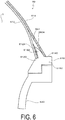
- FIG. 6 is a cross-sectional view illustrating the structure in the vicinity of a mouthpiece 616 of an aircraft water tank 60 according to the conventional art.
- An outer peripheral surface of an inner liner 612 in which is formed an interior space S for holding water is covered by a fiber-reinforced resin layer 614.
- a first opening 6120 is formed in the inner liner 612 and a second opening 6140 in the fiber-reinforced resin layer 614 are coaxially provided in the center of a dome section.
- the mouthpiece 616 comprises a cylindrical mouthpiece body 6160 that passes through the first and second openings 6120, 6140, and an annular wall section 6162 that protrudes from the outer periphery of the mouthpiece body 6160 and extends outward in the radial direction between the portion of the inner liner 612 surrounding the first opening 6120 and the portion of the fiber-reinforced resin layer 614 surrounding the second opening 6140, and to which those respective sections of the inner liner 612 and the fiber-reinforced resin layer 614 are attached.
- the interior space S is closed off by fitting a cap 620 into an opening formed in the inner periphery of the mouthpiece body 6160.
- a reinforcing member (doubler) 6124 constituted by multiple layers of glass fibers is provided between the portion of the inner liner 612 surrounding the first opening 6120 and the annular wall section 6162.
- the reinforcing member 6124 is provided in order to protect the inner liner 612 from stress sustained from around the outer circumferential end of the annular wall section 6162.
- That portion located to the outside than the radius of the annular wall section 6162 is filled with a filler 622.
- the filler 622 serves to fill in the gap formed around the openings (first and second opening 6120, 6140) in the aircraft water tank 60, which takes on a dome shape when the fiber-reinforced resin layer 614 is wound around the inner liner 612.
- Patent Document 1 Japanese Unexamined Patent Application Publication No. 2011-251736A , discloses an aircraft water tank according to the preamble of claim 1.
- the present invention was conceived in view of these circumstances, and has an object of providing an aircraft water tank having a simplified configuration.
- an aircraft water tank according to the present invention is an aircraft water tank having the features of claim 1.
- the aircraft water tank is provided with a cylindrical section, dome sections provided on both sides of the cylindrical section, and a mouthpiece provided in a center of each of the dome sections; the dome sections being provided with an inner liner and a fiber-reinforced resin layer provided on an outer peripheral surface of the inner liner; the inner liner and the fiber-reinforced resin layer being provided with coaxially positioned openings; each of the mouthpieces being provided with a cylindrical mouthpiece body that passes through the openings, and an annular wall section that extends outward in a radial direction from around the entire outer circumference of the mouthpiece body between the inner liner and the fiber-reinforced resin layer, and is attached to the inner liner and the fiber-reinforced resin layer around the circumferences of the openings; and the annular wall sections having a surface shape on a side contacting the fiber-reinforced resin layer that is formed by a
- the surface shape of the annular wall sections of the mouthpieces contacting the fiber-reinforced resin layer conforms to a uniform tension curved surface, thereby allowing the dome sections to be imparted with uniform tension curved surface shapes by directly winding the fiber-reinforced resin layer around these surfaces.
- no gaps are formed around the openings, eliminating the need for the filler filling the space between the inner liner and the fiber-reinforced resin layer in conventional tanks.
- the surface shape of the annular wall sections has less curvature than in mouthpieces according to the conventional art, and the thickness of the outer circumferential ends of the mouthpieces is reduced. For this reason, the elasticity of the outer circumferential ends of the mouthpieces is improved, and stress near the outer circumferential ends can be widely dispersed, thereby eliminating the need for the conventional reinforcing member (doubler).
- the number of parts making up the aircraft water tank is reduced, which is advantageous for reducing costs. It is also possible to reduce the number of steps used to manufacture the aircraft water tank, allowing for improved production efficiency.
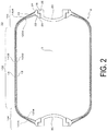
- FIG. 1 is an external perspective view of an aircraft water tank according to an embodiment
- FIG. 2 is a cross-sectional view along line A-A' of the configuration of the aircraft water tank
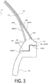
- FIG. 3 is a cross-sectional view of the main parts of the aircraft water tank.
- An aircraft water tank 8 is installed in an aircraft and serves to hold drinking water. As illustrated in FIG. 1 , the aircraft water tank 8 is installed at a suitable location within the aircraft so that the lengthwise direction of the aircraft water tank 8 is horizontally disposed with two mouthpieces 16 being sealed by removable caps 20.
- Water supply tank ports (water supply openings) 62 that communicate with the interior space S and are used to fill the tank with water or air or empty the tank of the same are provided at upward-facing locations at intermediate positions along the lengthwise direction of the aircraft water tank 8.
- a water supply tank port (not illustrated) that communicates with the interior space S is provided at down-facing location at intermediate positions along the lengthwise direction of the aircraft water tank 8.
- the water supply tank ports 62 are connected to an external water supply source, and water from the water supply source is supplied to the interior space S through the water supply tank ports 62.
- the water supply tank ports 62 are disconnected from the water supply source, and the water supply tank ports are connected to water supply pipes communicating with spouts installed within the aircraft.
- air is supplied from an air supply source installed within the aircraft to the interior space S through the water supply tank ports 62, thereby placing pressure upon the drinking water within the aircraft water tank 8, and supplying the drinking water to the spouts via the water supply tank ports and the water supply pipes.
- the aircraft water tank 8 is provided with a tank body 10 and mouthpieces 16.
- the tank body 10 comprises a cylindrical section 102, and dome sections 104 provided on both sides of the cylindrical section 102, the mouthpieces 16 being provided in the centers of the dome sections 104.
- the mouthpieces 16 constitute cleaning openings for cleaning the interior of the aircraft water tank 8.
- the cylindrical section 102 and the dome sections 104 are provided with an inner liner 12 and a fiber-reinforced resin layer 14 provided on an outer peripheral surface of the inner liner 12. Coaxially positioned openings (first opening 22, second opening 24) for the mouthpieces 16 are provided in the inner liner 12 and the fiber-reinforced resin layer 14 in the centers of the dome sections 104.
- the cylindrical section 102 and the dome sections 104 are integrally formed in the inner liner 12, and form an interior space S for holding a liquid (drinking water).
- Coaxial first openings 22 are provided in the two lengthwise-directional ends of the inner liner 12 forming the centers of the dome sections 104. Designating that portion of the inner liner 12 that forms the cylindrical section 102 as body section 1202 and those portions of the inner liner 12 that form the dome sections 104 as dome sections 1204, the first openings 22 are formed in the centers of the dome sections 1204.
- the inner liner 12 is formed, for example, from a polyolefin.
- the inner liner 12 may also be formed from various other conventionally known synthetic resins, such as acrylonitrile butadiene styrene (ABS) resin or polyethylene terephthalate (PET) resin.
- ABS acrylonitrile butadiene styrene
- PET polyethylene terephthalate
- the fiber-reinforced resin layer 14 comprises second openings 24 positioned coaxially with the first openings 22, and covers the outer peripheral surface of the inner liner 12. Designating that portion of the fiber-reinforced resin layer 14 that forms the cylindrical section 102 and is laid over the body section 1202 of the inner liner 12 as body section 1402 and those portions of the fiber-reinforced resin layer 14 that form the dome sections 104 and are laid over the dome sections 1204 of the inner liner 12 as dome sections 1404, the second openings 24 are formed in the centers of the dome sections 1404.
- the fiber-reinforced resin layer 14 is formed via a filament winding method in which reinforcing fibers (filaments) impregnated with a thermosetting resin are wound around the outer peripheral surface of the inner liner 12, after which the thermosetting resin is thermally cured.
- Various conventionally known synthetic resins such as epoxy resin can be used as the thermosetting resin.
- Various conventionally known fibers such as carbon fibers or glass fibers can be used as the reinforcing fibers.
- the mouthpieces 16 are provided with caps 20 that are capable of engaging with and detaching from the mouthpieces 16.
- the mouthpieces 16 comprise cylindrical mouthpiece bodies 26 and annular wall sections 28 that extend outward in the radial direction around the entire outer circumferences of the mouthpiece bodies 26.
- the mouthpiece bodies 26 pass through the first and second openings 22, 24, and the interior circumferences thereof communicate with the interior space S.
- the mouthpieces 16 are formed, for example, from a synthetic resin of superior chemical resistance. Various known synthetic resins, such as glass-fiber-containing polyphenylsulfone resin, can be used for this synthetic resin.
- Mouthpiece side openings 32 are provided in the interior circumferences of the mouthpiece bodies 26.
- the mouthpiece side openings 32 comprise larger-diameter hole sections 3202 into which the caps 20 are fitted and smaller-diameter hole sections 3204 continuous with the larger-diameter hole sections 3202.
- the annular wall sections 28 are disposed between the inner liner 12 and the fiber-reinforced resin layer 14. More specifically, the annular wall sections 28 extend outward in the radial direction of the first and second openings 22, 24 between those portions of the inner liner 12 that surround the first openings 22 and those portions of the fiber-reinforced resin layer 14 that surround the second openings 24.
- One side of each of the annular wall sections 28 with respect to the through-thickness direction is designated as an inner surface 2802 that faces the interior of the aircraft water tank 8, and the other side is designated as an outer surface 2804 that faces the exterior of the aircraft water tank 8.
- the entireties of the inner surfaces 2802 of the annular wall sections 28 are attached to those portions of the inner liner 12 that surround the first openings 22.
- the entireties of the outer surfaces 2804 of the annular wall sections 28 are attached to those portions of the fiber-reinforced resin layer 14 that surround the second openings 24.
- the thickness of the annular wall sections 28 decreases from base sections 282 by the mouthpiece bodies 26 toward outer circumferential ends 284.
- the shape of the surfaces of the annular wall sections 28 on the sides thereof contacting the fiber-reinforced resin layer 14, i.e., the outer surfaces 2804, are formed by uniform tension curved surfaces.
- the shapes of the dome sections 104 of the aircraft water tank 8 are formed by uniform tension curved surfaces in which stress caused by internal pressure is uniformly distributed throughout the fiber-reinforced resin layer 14 over the dome sections 104.
- the outer surfaces 2804 of the annular wall sections 28 contacting the fiber-reinforced resin layer 14 conform to the uniform tension curved surfaces, and the outer peripheral surface of the fiber-reinforced resin layer 14, i.e., the shapes of the dome sections 104 of the aircraft water tank 8, are imparted with the shape of the uniform tension curved surfaces by winding the fiber-reinforced resin layer 14 over the outer surfaces 2804.
- the caps 20 are fitted into the mouthpiece side openings 32 to seal off the interior space S.
- the caps 20 are provided with larger-diameter sections 2002 that releasably join to the larger-diameter hole sections 3202, and smaller-diameter sections 2004 that are fitted into the smaller-diameter hole sections 3204.
- the surfaces of the annular wall sections of mouthpieces in a tank according to the conventional art have shapes exhibiting greater curvature than a uniform tension curved surface, and have shorter radii from the centers of the mouthpieces 16 than that of the mouthpieces 16 of the present embodiment (see FIG. 6 ). For this reason, when the fiber-reinforced resin layer 14 in the dome sections 104 is wound along the uniform tension curved surfaces, gaps are formed between the fiber-reinforced resin layer 14 and the inner liner 12, creating a need to fill these gaps with a filler (see FIG. 6 ).
- the surface shapes of the annular wall sections 28 of the mouthpieces 16 conform to uniform tension curved surfaces, thereby allowing the dome sections 104 to be imparted with uniform tension curved surface shapes by directly winding the fiber-reinforced resin layer 14 around these surfaces. This eliminates the need for a filler around the openings 16 of the aircraft water tank 8 according to the present embodiment.
- the surface shape of the annular wall sections 28 of the mouthpieces 16 of the present embodiment has less curvature than in mouthpieces according to the conventional art, and the radii from the centers of the mouthpieces 16 are longer.
- the outer circumferential ends 284 of the mouthpieces 16 of the present embodiment are thinner than in mouthpieces according to the conventional art when the base sections 282 contacting the mouthpiece bodies 26 are of identical thickness.
- the elasticity of the outer circumferential ends 284 is improved, and stress near the outer circumferential ends 284 can be widely dispersed, thereby eliminating the need for the conventional reinforcing member (doubler; see FIG. 6 ).
- the second embodiment differs from the first embodiment in that portions (opening-surrounding sections) 120 of the inner liner 12 surrounding the first openings 22 are thicker than the other parts thereof, and is otherwise similar to the first embodiment.
- portions (opening-surrounding sections) 120 of the inner liner 12 surrounding the first openings 22 are thicker than the other parts thereof, and is otherwise similar to the first embodiment.
- elements identical or similar to those of the first embodiment are described using identical reference numerals.
- the inner liner 12 of the second embodiment is formed from a polyolefin.
- Polyolefin is a general term for polymers synthesized from an olefin or alkene monomer.
- polypropylene a typical polyolefin, is a resin composed of polymerized propylene, and is one type of thermoplastic plastic. It has an ordinary heat resistance temperature of 100 to 140°C, and, at 0.9 to 0.91, the smallest specific gravity of all types of plastic. It is a material exhibiting comparatively good heat resistance, as well as superior mechanical strength. It is produced in large amounts, second only to polyethylene, and is inexpensive.
- Polyolefin has adhesion-resistant properties, but the adhesiveness thereof can be improved via an adhesive pretreatment such as Corona discharge treatment or ITRO treatment. It is a material of superior mechanical properties (tensile strength, compressive strength, and impact strength), high surface hardness, and superior wear resistance. In addition, because it has a high heat resistance temperature, a high curing temperature can be set, allowing for reduced curing time. Moreover, it is highly resistant to acidic and alkaline solutions constituting the disinfectants used to clean fuselage pipes and aircraft water tanks.
- the inner liner 12 is molded from a polyolefin material via blow molding.
- a mold 40 used to perform blow molding is formed so that the interior thereof conforms to the shape of the inner liner 12. Specifically, a larger-diameter section 402 corresponding to the cylindrical section 102 of the aircraft water tank 8, two curved sections 404 corresponding to the dome sections 104, and two smaller-diameter sections 406 corresponding to the mouthpieces 16 are formed within the mold 40.
- the mold 40 is disposed so that the axial direction of the larger-diameter section 402 is vertically oriented, with the inside of the smaller-diameter section 406 positioned above constituting an upper opening 412 and the inside of the smaller-diameter section 406 positioned below constituting a lower opening 414, and the upper opening 412 and the lower opening 414 being disposed along the direction of gravity.
- a parison 50 of a plasticized resin material polyolefin
- the parison 50 is extruded from a donut-shaped head not illustrated in the drawings, and is tubular in shape.
- Compressed air B is then blown into the interior of the lower end of the parison 50 in the lower opening 414.
- the compressed air B causes the parison 50 to swell and press against the inner wall of the mold 40, thereby molding a molded resin article, i.e., an inner liner 12, conforming to the shape of the mold 40.
- the thickness and shape of the molded article can be adjusted by adjusting the gap of the head to control the thickness of the parison 50 (i.e., via parison control) when introducing the parison 50 via the upper opening 412.
- the thickness of the parison 50 is controlled so that the thickness of the parison 50 in the upper and lower smaller-diameter sections 406 is greater than the thickness of the parison 50 in the larger-diameter section 402. This allows the areas near the water supply sections corresponding to the smaller-diameter sections 406, i.e., the portions (opening-surrounding sections) 120 of the inner liner 12 surrounding the first openings 22, to be imparted with a greater thickness than the other portions thereof.
- a typical conventional method for molding the inner liner 12 is inflation molding. This is because ABS resin, widely used as the material of the inner liner 12 in the conventional art, has a narrow range of temperatures suitable for molding, making it difficult to blow mold.
- inflation molding a tubular piece of a solid resin material is conveyed into a mold, and a molded article having a shape conforming to the mold is molded by applying pressure and heat thereto.
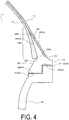
- the dome sections 104 of the aircraft water tank 8, especially the areas near the mouthpieces 16, have a high level of curvature, causing the resin material to become thin. For this reason, it was previously impossible to impart the opening-surrounding sections 120 of the inner liner 12 with a greater thickness than the other parts thereof as illustrated in FIG. 4 .
- the use of a polyolefin allows the inner liner 12 to be molded comparatively easily via blow molding, and the opening-surrounding sections 120 of the inner liner 12 can be imparted with a greater thickness than the other parts thereof via parison control as appropriate. Imparting the opening-surrounding sections 120 of the inner liner 12 with a greater thickness than the other parts thereof disperses the stress to which the inner liner 12 is subjected at the outer circumferential ends 284 of the annular wall sections 28, which is advantageous in ensuring the strength of the inner liner 12.
- the use of a polyolefin for the material of the inner liner 12 in the present embodiment allows the inner liner 12 to be imparted with higher heat resistance, wear resistance, and chemical resistance than would be yielded by conventional ABS resin or the like.
Landscapes
- Engineering & Computer Science (AREA)
- Mechanical Engineering (AREA)
- Ceramic Engineering (AREA)
- Chemical & Material Sciences (AREA)
- Composite Materials (AREA)
- Aviation & Aerospace Engineering (AREA)
- Moulding By Coating Moulds (AREA)
- Rigid Containers With Two Or More Constituent Elements (AREA)
- Pressure Vessels And Lids Thereof (AREA)
Description
- The present invention relates to an aircraft water tank.
- An aircraft water tank provided with a tank body comprising a cylindrical section and dome sections provided on both sides of the cylindrical section, and mouthpieces provided in the centers of the dome sections, has previously been proposed.
The tank body is constituted by an inner liner in which is formed an interior space for holding water, and a fiber-reinforced resin layer covering an outer peripheral surface of the inner liner.
Coaxial first and second openings in the inner liner and the fiber-reinforced resin layer are provided in the centers of the dome sections, and the mouthpieces are passed through the first and second openings and attached to the inner liner and the fiber-reinforced resin layer, and communicate with the interior space (see Patent Document 1). -
FIG. 6 is a cross-sectional view illustrating the structure in the vicinity of amouthpiece 616 of anaircraft water tank 60 according to the conventional art. An outer peripheral surface of aninner liner 612 in which is formed an interior space S for holding water is covered by a fiber-reinforcedresin layer 614. Afirst opening 6120 is formed in theinner liner 612 and a second opening 6140 in the fiber-reinforcedresin layer 614 are coaxially provided in the center of a dome section.
Themouthpiece 616 comprises acylindrical mouthpiece body 6160 that passes through the first andsecond openings annular wall section 6162 that protrudes from the outer periphery of themouthpiece body 6160 and extends outward in the radial direction between the portion of theinner liner 612 surrounding the first opening 6120 and the portion of the fiber-reinforcedresin layer 614 surrounding the second opening 6140, and to which those respective sections of theinner liner 612 and the fiber-reinforcedresin layer 614 are attached. The interior space S is closed off by fitting acap 620 into an opening formed in the inner periphery of themouthpiece body 6160. - A reinforcing member (doubler) 6124 constituted by multiple layers of glass fibers is provided between the portion of the
inner liner 612 surrounding thefirst opening 6120 and theannular wall section 6162. The reinforcingmember 6124 is provided in order to protect theinner liner 612 from stress sustained from around the outer circumferential end of theannular wall section 6162.
Of the portion of theinner liner 612 surrounding the first opening 6120, that portion located to the outside than the radius of theannular wall section 6162 is filled with afiller 622. Thefiller 622 serves to fill in the gap formed around the openings (first and second opening 6120, 6140) in theaircraft water tank 60, which takes on a dome shape when the fiber-reinforcedresin layer 614 is wound around theinner liner 612. - Patent Document 1, Japanese Unexamined Patent Application Publication No.
2011-251736A - In the aircraft water take 60 according to the conventional art, as discussed above, it is necessary to provide a plurality of reinforcing members (reinforcing
member 6124, fillers 622) around the openings in order to protect theinner liner 612 from stress sustained from around the outer circumferential end of theannular wall section 6162 and to fill in the gap formed around the openings (first andsecond openings 6120, 6140) when the fiber-reinforcedresin layer 614 is wound around theinner liner 612. This increases the number of parts making up the aircraft water tank, leading to a problematic increase in the manufacturing cost of the aircraft water tank. The aircraft water tank according to the conventional art also presents the problem that the manufacturing process is complicated by the process of adding the reinforcing members. - The present invention was conceived in view of these circumstances, and has an object of providing an aircraft water tank having a simplified configuration.
- In order to achieve the object proposed above, an aircraft water tank according to the present invention is an aircraft water tank having the features of claim 1. The aircraft water tank is provided with a cylindrical section, dome sections provided on both sides of the cylindrical section, and a mouthpiece provided in a center of each of the dome sections; the dome sections being provided with an inner liner and a fiber-reinforced resin layer provided on an outer peripheral surface of the inner liner; the inner liner and the fiber-reinforced resin layer being provided with coaxially positioned openings; each of the mouthpieces being provided with a cylindrical mouthpiece body that passes through the openings, and an annular wall section that extends outward in a radial direction from around the entire outer circumference of the mouthpiece body between the inner liner and the fiber-reinforced resin layer, and is attached to the inner liner and the fiber-reinforced resin layer around the circumferences of the openings; and the annular wall sections having a surface shape on a side contacting the fiber-reinforced resin layer that is formed by a uniform tension curved surface.
- In accordance with the present invention, the surface shape of the annular wall sections of the mouthpieces contacting the fiber-reinforced resin layer conforms to a uniform tension curved surface, thereby allowing the dome sections to be imparted with uniform tension curved surface shapes by directly winding the fiber-reinforced resin layer around these surfaces. As a result, no gaps are formed around the openings, eliminating the need for the filler filling the space between the inner liner and the fiber-reinforced resin layer in conventional tanks.
- In addition, the surface shape of the annular wall sections has less curvature than in mouthpieces according to the conventional art, and the thickness of the outer circumferential ends of the mouthpieces is reduced. For this reason, the elasticity of the outer circumferential ends of the mouthpieces is improved, and stress near the outer circumferential ends can be widely dispersed, thereby eliminating the need for the conventional reinforcing member (doubler).
- As a result, the number of parts making up the aircraft water tank is reduced, which is advantageous for reducing costs. It is also possible to reduce the number of steps used to manufacture the aircraft water tank, allowing for improved production efficiency.
-
- FIG. 1
- is an external perspective view of an aircraft water tank according to an embodiment of the present invention.
- FIG. 2
- is a cross-sectional view along line A-A' of configuration of an aircraft water tank according to a first embodiment, not being part of the present invention.
- FIG. 3
- is a cross-sectional view of the main parts of the aircraft water tank according to the first embodiment.
- FIG. 4
- is a cross-sectional view of the main parts of an aircraft water tank according to a second embodiment, being part of the present invention.
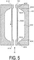
- FIG. 5
- is an illustration of a method for manufacturing an inner liner of the second embodiment.
- FIG. 6
- is a cross-sectional view of the structure near an opening in an aircraft water tank according to the conventional art.
- Next, embodiments will be described with reference to the drawings.
-
FIG. 1 is an external perspective view of an aircraft water tank according to an embodiment,FIG. 2 is a cross-sectional view along line A-A' of the configuration of the aircraft water tank, andFIG. 3 is a cross-sectional view of the main parts of the aircraft water tank. - An
aircraft water tank 8 is installed in an aircraft and serves to hold drinking water. As illustrated inFIG. 1 , theaircraft water tank 8 is installed at a suitable location within the aircraft so that the lengthwise direction of theaircraft water tank 8 is horizontally disposed with twomouthpieces 16 being sealed byremovable caps 20. - Water supply tank ports (water supply openings) 62 that communicate with the interior space S and are used to fill the tank with water or air or empty the tank of the same are provided at upward-facing locations at intermediate positions along the lengthwise direction of the
aircraft water tank 8. A water supply tank port (not illustrated) that communicates with the interior space S is provided at down-facing location at intermediate positions along the lengthwise direction of theaircraft water tank 8. - If the
aircraft water tank 8 is used to hold drinking water, the watersupply tank ports 62 are connected to an external water supply source, and water from the water supply source is supplied to the interior space S through the watersupply tank ports 62. - Once the interior space S is filled with drinking water, the water
supply tank ports 62 are disconnected from the water supply source, and the water supply tank ports are connected to water supply pipes communicating with spouts installed within the aircraft. - To supply drinking water from the
aircraft water tank 8 to spouts or the like within the aircraft, air is supplied from an air supply source installed within the aircraft to the interior space S through the watersupply tank ports 62, thereby placing pressure upon the drinking water within theaircraft water tank 8, and supplying the drinking water to the spouts via the water supply tank ports and the water supply pipes. - As illustrated in
FIG. 2 andFIG. 3 , theaircraft water tank 8 is provided with atank body 10 andmouthpieces 16. Thetank body 10 comprises acylindrical section 102, anddome sections 104 provided on both sides of thecylindrical section 102, themouthpieces 16 being provided in the centers of thedome sections 104. Themouthpieces 16 constitute cleaning openings for cleaning the interior of theaircraft water tank 8. Thecylindrical section 102 and thedome sections 104 are provided with aninner liner 12 and a fiber-reinforcedresin layer 14 provided on an outer peripheral surface of theinner liner 12. Coaxially positioned openings (first opening 22, second opening 24) for themouthpieces 16 are provided in theinner liner 12 and the fiber-reinforcedresin layer 14 in the centers of thedome sections 104. - More specifically, the
cylindrical section 102 and thedome sections 104 are integrally formed in theinner liner 12, and form an interior space S for holding a liquid (drinking water). Coaxialfirst openings 22 are provided in the two lengthwise-directional ends of theinner liner 12 forming the centers of thedome sections 104. Designating that portion of theinner liner 12 that forms thecylindrical section 102 asbody section 1202 and those portions of theinner liner 12 that form thedome sections 104 asdome sections 1204, thefirst openings 22 are formed in the centers of thedome sections 1204. - The
inner liner 12 is formed, for example, from a polyolefin. Theinner liner 12 may also be formed from various other conventionally known synthetic resins, such as acrylonitrile butadiene styrene (ABS) resin or polyethylene terephthalate (PET) resin. - The fiber-reinforced
resin layer 14 comprisessecond openings 24 positioned coaxially with thefirst openings 22, and covers the outer peripheral surface of theinner liner 12. Designating that portion of the fiber-reinforcedresin layer 14 that forms thecylindrical section 102 and is laid over thebody section 1202 of theinner liner 12 asbody section 1402 and those portions of the fiber-reinforcedresin layer 14 that form thedome sections 104 and are laid over thedome sections 1204 of theinner liner 12 asdome sections 1404, thesecond openings 24 are formed in the centers of thedome sections 1404.
The fiber-reinforcedresin layer 14 is formed via a filament winding method in which reinforcing fibers (filaments) impregnated with a thermosetting resin are wound around the outer peripheral surface of theinner liner 12, after which the thermosetting resin is thermally cured.
Various conventionally known synthetic resins such as epoxy resin can be used as the thermosetting resin. Various conventionally known fibers such as carbon fibers or glass fibers can be used as the reinforcing fibers. - The
mouthpieces 16 are provided withcaps 20 that are capable of engaging with and detaching from themouthpieces 16. As illustrated inFIG. 3 , themouthpieces 16 comprisecylindrical mouthpiece bodies 26 andannular wall sections 28 that extend outward in the radial direction around the entire outer circumferences of themouthpiece bodies 26.
Themouthpiece bodies 26 pass through the first andsecond openings
In the present embodiment, themouthpieces 16 are formed, for example, from a synthetic resin of superior chemical resistance. Various known synthetic resins, such as glass-fiber-containing polyphenylsulfone resin, can be used for this synthetic resin.
Mouthpiece side openings 32 are provided in the interior circumferences of themouthpiece bodies 26.
Themouthpiece side openings 32 comprise larger-diameter hole sections 3202 into which thecaps 20 are fitted and smaller-diameter hole sections 3204 continuous with the larger-diameter hole sections 3202. - The
annular wall sections 28 are disposed between theinner liner 12 and the fiber-reinforcedresin layer 14.
More specifically, theannular wall sections 28 extend outward in the radial direction of the first andsecond openings inner liner 12 that surround thefirst openings 22 and those portions of the fiber-reinforcedresin layer 14 that surround thesecond openings 24. One side of each of theannular wall sections 28 with respect to the through-thickness direction is designated as aninner surface 2802 that faces the interior of theaircraft water tank 8, and the other side is designated as anouter surface 2804 that faces the exterior of theaircraft water tank 8.
The entireties of theinner surfaces 2802 of theannular wall sections 28 are attached to those portions of theinner liner 12 that surround thefirst openings 22.
The entireties of theouter surfaces 2804 of theannular wall sections 28 are attached to those portions of the fiber-reinforcedresin layer 14 that surround thesecond openings 24.
The thickness of theannular wall sections 28 decreases frombase sections 282 by themouthpiece bodies 26 toward outer circumferential ends 284. - The shape of the surfaces of the
annular wall sections 28 on the sides thereof contacting the fiber-reinforcedresin layer 14, i.e., theouter surfaces 2804, are formed by uniform tension curved surfaces. The shapes of thedome sections 104 of theaircraft water tank 8 are formed by uniform tension curved surfaces in which stress caused by internal pressure is uniformly distributed throughout the fiber-reinforcedresin layer 14 over thedome sections 104. Theouter surfaces 2804 of theannular wall sections 28 contacting the fiber-reinforcedresin layer 14 conform to the uniform tension curved surfaces, and the outer peripheral surface of the fiber-reinforcedresin layer 14, i.e., the shapes of thedome sections 104 of theaircraft water tank 8, are imparted with the shape of the uniform tension curved surfaces by winding the fiber-reinforcedresin layer 14 over theouter surfaces 2804. - As illustrated in
FIG. 3 , thecaps 20 are fitted into themouthpiece side openings 32 to seal off the interior space S.
Thecaps 20 are provided with larger-diameter sections 2002 that releasably join to the larger-diameter hole sections 3202, and smaller-diameter sections 2004 that are fitted into the smaller-diameter hole sections 3204. - Next, the functions and effects of the
aircraft water tank 8 will be described.
The surfaces of the annular wall sections of mouthpieces in a tank according to the conventional art have shapes exhibiting greater curvature than a uniform tension curved surface, and have shorter radii from the centers of themouthpieces 16 than that of themouthpieces 16 of the present embodiment (seeFIG. 6 ). For this reason, when the fiber-reinforcedresin layer 14 in thedome sections 104 is wound along the uniform tension curved surfaces, gaps are formed between the fiber-reinforcedresin layer 14 and theinner liner 12, creating a need to fill these gaps with a filler (seeFIG. 6 ).
In the present embodiment, by contrast, the surface shapes of theannular wall sections 28 of themouthpieces 16 conform to uniform tension curved surfaces, thereby allowing thedome sections 104 to be imparted with uniform tension curved surface shapes by directly winding the fiber-reinforcedresin layer 14 around these surfaces. This eliminates the need for a filler around theopenings 16 of theaircraft water tank 8 according to the present embodiment. - In addition, the surface shape of the
annular wall sections 28 of themouthpieces 16 of the present embodiment has less curvature than in mouthpieces according to the conventional art, and the radii from the centers of themouthpieces 16 are longer. For this reason, the outer circumferential ends 284 of themouthpieces 16 of the present embodiment are thinner than in mouthpieces according to the conventional art when thebase sections 282 contacting themouthpiece bodies 26 are of identical thickness. For this reason, the elasticity of the outer circumferential ends 284 is improved, and stress near the outer circumferential ends 284 can be widely dispersed, thereby eliminating the need for the conventional reinforcing member (doubler; seeFIG. 6 ).
Thus, there is likewise no need for a reinforcing member between the outer circumferences of themouthpieces 16 and theinner liner 12 in the present embodiment.
As a result, the number of parts making up theaircraft water tank 8 is reduced in the present embodiment, which is advantageous for reducing costs. It is also possible to reduce the number of steps used to manufacture theaircraft water tank 8, allowing for improved production efficiency. - Next, a second embodiment will be described with reference to
FIGS. 4 and5 .
As illustrated inFIG. 4 , the second embodiment differs from the first embodiment in that portions (opening-surrounding sections) 120 of theinner liner 12 surrounding thefirst openings 22 are thicker than the other parts thereof, and is otherwise similar to the first embodiment. In the embodiment described hereafter, elements identical or similar to those of the first embodiment are described using identical reference numerals. - The
inner liner 12 of the second embodiment is formed from a polyolefin.
"Polyolefin" is a general term for polymers synthesized from an olefin or alkene monomer.
For example, polypropylene, a typical polyolefin, is a resin composed of polymerized propylene, and is one type of thermoplastic plastic. It has an ordinary heat resistance temperature of 100 to 140°C, and, at 0.9 to 0.91, the smallest specific gravity of all types of plastic. It is a material exhibiting comparatively good heat resistance, as well as superior mechanical strength. It is produced in large amounts, second only to polyethylene, and is inexpensive.
Polyolefin has adhesion-resistant properties, but the adhesiveness thereof can be improved via an adhesive pretreatment such as Corona discharge treatment or ITRO treatment. It is a material of superior mechanical properties (tensile strength, compressive strength, and impact strength), high surface hardness, and superior wear resistance. In addition, because it has a high heat resistance temperature, a high curing temperature can be set, allowing for reduced curing time. Moreover, it is highly resistant to acidic and alkaline solutions constituting the disinfectants used to clean fuselage pipes and aircraft water tanks. - A method for manufacturing the
inner liner 12 made from a polyolefin material will be described usingFIG. 5 .
In the present embodiment, theinner liner 12 is molded from a polyolefin material via blow molding. Amold 40 used to perform blow molding is formed so that the interior thereof conforms to the shape of theinner liner 12. Specifically, a larger-diameter section 402 corresponding to thecylindrical section 102 of theaircraft water tank 8, twocurved sections 404 corresponding to thedome sections 104, and two smaller-diameter sections 406 corresponding to themouthpieces 16 are formed within themold 40. Themold 40 is disposed so that the axial direction of the larger-diameter section 402 is vertically oriented, with the inside of the smaller-diameter section 406 positioned above constituting anupper opening 412 and the inside of the smaller-diameter section 406 positioned below constituting alower opening 414, and theupper opening 412 and thelower opening 414 being disposed along the direction of gravity.
To mold theinner liner 12, aparison 50 of a plasticized resin material (polyolefin) is introduced via theupper opening 412 of themold 40, and the lower part of theparison 50 is positioned within thelower opening 414. Theparison 50 is extruded from a donut-shaped head not illustrated in the drawings, and is tubular in shape. Compressed air B is then blown into the interior of the lower end of theparison 50 in thelower opening 414. The compressed air B causes theparison 50 to swell and press against the inner wall of themold 40, thereby molding a molded resin article, i.e., aninner liner 12, conforming to the shape of themold 40. - The thickness and shape of the molded article can be adjusted by adjusting the gap of the head to control the thickness of the parison 50 (i.e., via parison control) when introducing the
parison 50 via theupper opening 412. Specifically, as illustrated inFIG. 5 , the thickness of theparison 50 is controlled so that the thickness of theparison 50 in the upper and lower smaller-diameter sections 406 is greater than the thickness of theparison 50 in the larger-diameter section 402. This allows the areas near the water supply sections corresponding to the smaller-diameter sections 406, i.e., the portions (opening-surrounding sections) 120 of theinner liner 12 surrounding thefirst openings 22, to be imparted with a greater thickness than the other portions thereof. - A typical conventional method for molding the
inner liner 12 is inflation molding. This is because ABS resin, widely used as the material of theinner liner 12 in the conventional art, has a narrow range of temperatures suitable for molding, making it difficult to blow mold.
In inflation molding, a tubular piece of a solid resin material is conveyed into a mold, and a molded article having a shape conforming to the mold is molded by applying pressure and heat thereto. In inflation molding, thedome sections 104 of theaircraft water tank 8, especially the areas near themouthpieces 16, have a high level of curvature, causing the resin material to become thin. For this reason, it was previously impossible to impart the opening-surroundingsections 120 of theinner liner 12 with a greater thickness than the other parts thereof as illustrated inFIG. 4 . - In the present embodiment, the use of a polyolefin allows the
inner liner 12 to be molded comparatively easily via blow molding, and the opening-surroundingsections 120 of theinner liner 12 can be imparted with a greater thickness than the other parts thereof via parison control as appropriate.
Imparting the opening-surroundingsections 120 of theinner liner 12 with a greater thickness than the other parts thereof disperses the stress to which theinner liner 12 is subjected at the outer circumferential ends 284 of theannular wall sections 28, which is advantageous in ensuring the strength of theinner liner 12. - In addition, the use of a polyolefin for the material of the
inner liner 12 in the present embodiment allows theinner liner 12 to be imparted with higher heat resistance, wear resistance, and chemical resistance than would be yielded by conventional ABS resin or the like. -
- 8:
- Aircraft water tank
- 10:
- Tank body
- 12:
- Inner liner
- 14:
- Fiber-reinforced resin layer
- 16:
- Mouthpiece
- 20:
- Cap
- 22:
- First opening
- 24:
- Second opening
- 26:
- Mouthpiece body
- 28:
- Annular wall section
- 32:
- Mouthpiece side opening
- 102:
- Cylindrical section
- 104:
- Dome section
Claims (1)
- An aircraft water tank (8) comprising:a cylindrical section (102);dome sections (104) provided on both sides of the cylindrical section (102); anda mouthpiece (16) provided in a center of each of the dome sections (104) ;the dome sections (104) being provided with an inner liner (12) and a fiber-reinforced resin layer (14) provided on an outer peripheral surface of the inner liner (12);
the inner liner (12) and the fiber-reinforced resin layer (14) being provided with coaxially positioned first and second openings (22, 24), respectively; each of the mouthpieces (16) being provided with a cylindrical mouthpiece body (26) that passes through the openings (22, 24), and an annular wall section (28) that extends outward in a radial direction from around the entire outer circumference of the mouthpiece body (26) between the inner liner (12) and the fiber-reinforced resin layer (14), and is attached to the inner liner (12) and the fiber-reinforced resin layer (14) around the circumferences of the openings (22, 24), wherein the annular wall section (28) has an outer surface shape on a side (2804) directly attached to the fiber-reinforced resin layer (14), the surface shape of the annular wall section (28) being formed by a uniform tension curved surface, wherein the entireties of the outer surfaces (2804) of the annular wall sections (28) are attached to those portions of the fiber-reinforced resin layer (14) surrounding the second openings (24); wherein the uniform tension curved surface is a surface by means of which stress caused by internal pressure of the aircraft water tank is uniformly distributed throughout the fiber-reinforced resin layer (14) over the dome sections (104), and
wherein the inner liner (12) is formed from a polyolefin,
characterised in that the inner liner (12) is thicker in portions thereof surrounding the first openings (22) than in other portions thereof.
Applications Claiming Priority (2)
| Application Number | Priority Date | Filing Date | Title |
|---|---|---|---|
| JP2013224978A JP2015085946A (en) | 2013-10-30 | 2013-10-30 | Aircraft water tank |
| PCT/JP2014/077971 WO2015064424A1 (en) | 2013-10-30 | 2014-10-21 | Aircraft water tank |
Publications (3)
| Publication Number | Publication Date |
|---|---|
| EP3064450A1 EP3064450A1 (en) | 2016-09-07 |
| EP3064450A4 EP3064450A4 (en) | 2017-04-19 |
| EP3064450B1 true EP3064450B1 (en) | 2019-09-18 |
Family
ID=53004032
Family Applications (1)
| Application Number | Title | Priority Date | Filing Date |
|---|---|---|---|
| EP14858683.7A Not-in-force EP3064450B1 (en) | 2013-10-30 | 2014-10-21 | Aircraft water tank |
Country Status (5)
| Country | Link |
|---|---|
| US (1) | US20160257403A1 (en) |
| EP (1) | EP3064450B1 (en) |
| JP (1) | JP2015085946A (en) |
| CN (1) | CN105636882A (en) |
| WO (1) | WO2015064424A1 (en) |
Families Citing this family (12)
| Publication number | Priority date | Publication date | Assignee | Title |
|---|---|---|---|---|
| JP6766356B2 (en) * | 2014-08-25 | 2020-10-14 | 横浜ゴム株式会社 | Structure of nozzle for piping of fluid tank |
| JP6582563B2 (en) | 2015-06-02 | 2019-10-02 | 横浜ゴム株式会社 | Aircraft water tank |
| US11067227B2 (en) | 2016-09-28 | 2021-07-20 | The Yokohama Rubber Co., Ltd. | Aircraft water tank and method for manufacturing same |
| JP6829985B2 (en) * | 2016-11-28 | 2021-02-17 | 志郎 中村 | Continuous feeding device for lining material and continuous feeding device for resin tubes |
| US11939105B2 (en) | 2017-08-29 | 2024-03-26 | Goodrich Corporation | 3D woven conformable tank |
| US11091266B2 (en) | 2017-08-29 | 2021-08-17 | Goodrich Corporation | Conformable tank fabricated using additive manufacturing |
| US10703481B2 (en) * | 2017-08-29 | 2020-07-07 | Goodrich Corporation | Conformable tank with sandwich structure walls |
| US10816138B2 (en) | 2017-09-15 | 2020-10-27 | Goodrich Corporation | Manufacture of a conformable pressure vessel |
| JP6399193B1 (en) * | 2017-11-07 | 2018-10-03 | 横浜ゴム株式会社 | Aircraft water tank |
| JP6515982B1 (en) * | 2017-11-22 | 2019-05-22 | 横浜ゴム株式会社 | Aircraft water tank and method of manufacturing the same |
| US20200189786A1 (en) * | 2018-12-12 | 2020-06-18 | Goodrich Corporation | Composite potable water tank and method of forming |
| RU192384U1 (en) * | 2019-06-17 | 2019-09-16 | Анатолий Александрович Катаев | FIRE EXTINGUISHING LIQUID RESERVOIR |
Family Cites Families (13)
| Publication number | Priority date | Publication date | Assignee | Title |
|---|---|---|---|---|
| JPH11101397A (en) * | 1997-09-26 | 1999-04-13 | Mitsubishi Heavy Ind Ltd | Pressure vessel of cylindrical shape with frp-made dome |
| NL1014290C2 (en) * | 2000-02-04 | 2001-08-07 | Advanced Lightweight Const Gro | Fiber-reinforced pressure vessel and method for making a fiber-reinforced pressure vessel. |
| DE10360953B4 (en) * | 2002-12-27 | 2011-04-07 | Toyoda Gosei Co., Ltd., Nishikasugai-gun | pressure vessel |
| JP2005113971A (en) * | 2003-10-03 | 2005-04-28 | Fuji Heavy Ind Ltd | Liner for pressure resistant container |
| CN201082777Y (en) * | 2007-02-14 | 2008-07-09 | 王源生 | Combined water storage tank |
| JP4775776B2 (en) * | 2008-09-24 | 2011-09-21 | トヨタ自動車株式会社 | Gas tank and manufacturing method thereof |
| WO2011052714A1 (en) * | 2009-10-30 | 2011-05-05 | 独立行政法人 宇宙航空研究開発機構 | Joint structure for metal member and composite member |
| JP5179458B2 (en) * | 2009-11-11 | 2013-04-10 | 八千代工業株式会社 | Pressure vessel seal structure |
| JP5494241B2 (en) * | 2010-05-28 | 2014-05-14 | 横浜ゴム株式会社 | Manufacturing method of plastic liner for tank |
| JP5740846B2 (en) * | 2010-06-02 | 2015-07-01 | 横浜ゴム株式会社 | tank |
| JP2013002492A (en) * | 2011-06-14 | 2013-01-07 | Nissan Motor Co Ltd | Pressure vessel |
| EP2740584B1 (en) * | 2011-08-01 | 2019-02-27 | Showa Denko K.K. | Method for producing pressure vessel |
| CN202442097U (en) * | 2012-02-21 | 2012-09-19 | 浙江凯博压力容器有限公司 | Carbon fiber wrapped liner composite gas cylinder |
-
2013
- 2013-10-30 JP JP2013224978A patent/JP2015085946A/en active Pending
-
2014
- 2014-10-21 WO PCT/JP2014/077971 patent/WO2015064424A1/en active Application Filing
- 2014-10-21 US US15/033,403 patent/US20160257403A1/en not_active Abandoned
- 2014-10-21 EP EP14858683.7A patent/EP3064450B1/en not_active Not-in-force
- 2014-10-21 CN CN201480057210.2A patent/CN105636882A/en active Pending
Non-Patent Citations (1)
| Title |
|---|
| None * |
Also Published As
| Publication number | Publication date |
|---|---|
| CN105636882A (en) | 2016-06-01 |
| JP2015085946A (en) | 2015-05-07 |
| EP3064450A4 (en) | 2017-04-19 |
| US20160257403A1 (en) | 2016-09-08 |
| EP3064450A1 (en) | 2016-09-07 |
| WO2015064424A1 (en) | 2015-05-07 |
Similar Documents
| Publication | Publication Date | Title |
|---|---|---|
| EP3064450B1 (en) | Aircraft water tank | |
| JP6409887B2 (en) | Pressure vessel | |
| CN107709794B (en) | Method for producing a gas bag accumulator and gas bag accumulator produced according to said method | |
| JP5740846B2 (en) | tank | |
| US10995909B2 (en) | Hydrogen tank body and method of producing the same, and hydrogen tank and method of producing the same | |
| US9511892B2 (en) | Biaxial stretch blow-molded container | |
| ITUA20164707A1 (en) | PRESSURE CONTAINER | |
| CN103890479A (en) | Method of producing a composite pressure vessel, and composite pressure vessel | |
| CN101939158B (en) | Process for producing (part-)annular, fiber reinforced, polymer containing moldings from semifinished fiber composite material products | |
| JP6582563B2 (en) | Aircraft water tank | |
| CN105705856A (en) | High-pressure composite vessel and the method of manufacturing high-pressure composite vessel | |
| CN107206659B (en) | Preform and container for biaxial stretch blow molding | |
| EP4043171A3 (en) | Molded article with selectively varied core layer geometry and hot runner nozzles for producing same | |
| CN107206658A (en) | Liquid blow moulding equipment and preformed member | |
| JP2005003127A (en) | High pressure gas container | |
| EP3061592B1 (en) | Aircraft water tank and manufacturing method therefor | |
| US10920931B2 (en) | Pressure container and container body | |
| US20180036991A1 (en) | Profile Part With a Plurality of Layers | |
| CN207773695U (en) | A kind of tank body | |
| MXPA05009009A (en) | Container preform assembly and method of manufacture. | |
| TW201529363A (en) | Method of manufacturing carbon fiber wheel rim of bicycle and product thereof | |
| JP2017096308A (en) | Manufacturing method of high pressure tank | |
| KR20230090774A (en) | Pressure vessel manufacturing method using rubber and composite materials | |
| JP2022053892A (en) | Pressure container and device for producing blow molding | |
| CN114290641A (en) | Anti-impact pipe sleeve for injection mold extruder |
Legal Events
| Date | Code | Title | Description |
|---|---|---|---|
| PUAI | Public reference made under article 153(3) epc to a published international application that has entered the european phase |
Free format text: ORIGINAL CODE: 0009012 |
|
| 17P | Request for examination filed |
Effective date: 20160530 |
|
| AK | Designated contracting states |
Kind code of ref document: A1 Designated state(s): AL AT BE BG CH CY CZ DE DK EE ES FI FR GB GR HR HU IE IS IT LI LT LU LV MC MK MT NL NO PL PT RO RS SE SI SK SM TR |
|
| AX | Request for extension of the european patent |
Extension state: BA ME |
|
| DAX | Request for extension of the european patent (deleted) | ||
| A4 | Supplementary search report drawn up and despatched |
Effective date: 20170317 |
|
| RIC1 | Information provided on ipc code assigned before grant |
Ipc: B29D 22/00 20060101AFI20170313BHEP Ipc: B64D 11/02 20060101ALN20170313BHEP Ipc: B29L 31/00 20060101ALN20170313BHEP Ipc: B29C 70/08 20060101ALI20170313BHEP |
|
| STAA | Information on the status of an ep patent application or granted ep patent |
Free format text: STATUS: EXAMINATION IS IN PROGRESS |
|
| 17Q | First examination report despatched |
Effective date: 20171208 |
|
| REG | Reference to a national code |
Ref country code: DE Ref legal event code: R079 Ref document number: 602014054016 Country of ref document: DE Free format text: PREVIOUS MAIN CLASS: B65D0090000000 Ipc: B29D0022000000 |
|
| RIC1 | Information provided on ipc code assigned before grant |
Ipc: B29L 31/00 20060101ALN20190219BHEP Ipc: B29C 70/08 20060101ALI20190219BHEP Ipc: B29D 22/00 20060101AFI20190219BHEP Ipc: B64D 11/02 20060101ALN20190219BHEP |
|
| GRAP | Despatch of communication of intention to grant a patent |
Free format text: ORIGINAL CODE: EPIDOSNIGR1 |
|
| STAA | Information on the status of an ep patent application or granted ep patent |
Free format text: STATUS: GRANT OF PATENT IS INTENDED |
|
| INTG | Intention to grant announced |
Effective date: 20190402 |
|
| GRAS | Grant fee paid |
Free format text: ORIGINAL CODE: EPIDOSNIGR3 |
|
| GRAA | (expected) grant |
Free format text: ORIGINAL CODE: 0009210 |
|
| STAA | Information on the status of an ep patent application or granted ep patent |
Free format text: STATUS: THE PATENT HAS BEEN GRANTED |
|
| AK | Designated contracting states |
Kind code of ref document: B1 Designated state(s): AL AT BE BG CH CY CZ DE DK EE ES FI FR GB GR HR HU IE IS IT LI LT LU LV MC MK MT NL NO PL PT RO RS SE SI SK SM TR |
|
| REG | Reference to a national code |
Ref country code: GB Ref legal event code: FG4D |
|
| REG | Reference to a national code |
Ref country code: CH Ref legal event code: EP |
|
| REG | Reference to a national code |
Ref country code: DE Ref legal event code: R096 Ref document number: 602014054016 Country of ref document: DE |
|
| REG | Reference to a national code |
Ref country code: AT Ref legal event code: REF Ref document number: 1180783 Country of ref document: AT Kind code of ref document: T Effective date: 20191015 |
|
| REG | Reference to a national code |
Ref country code: IE Ref legal event code: FG4D |
|
| REG | Reference to a national code |
Ref country code: NL Ref legal event code: MP Effective date: 20190918 |
|
| PG25 | Lapsed in a contracting state [announced via postgrant information from national office to epo] |
Ref country code: FI Free format text: LAPSE BECAUSE OF FAILURE TO SUBMIT A TRANSLATION OF THE DESCRIPTION OR TO PAY THE FEE WITHIN THE PRESCRIBED TIME-LIMIT Effective date: 20190918 Ref country code: HR Free format text: LAPSE BECAUSE OF FAILURE TO SUBMIT A TRANSLATION OF THE DESCRIPTION OR TO PAY THE FEE WITHIN THE PRESCRIBED TIME-LIMIT Effective date: 20190918 Ref country code: NO Free format text: LAPSE BECAUSE OF FAILURE TO SUBMIT A TRANSLATION OF THE DESCRIPTION OR TO PAY THE FEE WITHIN THE PRESCRIBED TIME-LIMIT Effective date: 20191218 Ref country code: BG Free format text: LAPSE BECAUSE OF FAILURE TO SUBMIT A TRANSLATION OF THE DESCRIPTION OR TO PAY THE FEE WITHIN THE PRESCRIBED TIME-LIMIT Effective date: 20191218 Ref country code: SE Free format text: LAPSE BECAUSE OF FAILURE TO SUBMIT A TRANSLATION OF THE DESCRIPTION OR TO PAY THE FEE WITHIN THE PRESCRIBED TIME-LIMIT Effective date: 20190918 Ref country code: LT Free format text: LAPSE BECAUSE OF FAILURE TO SUBMIT A TRANSLATION OF THE DESCRIPTION OR TO PAY THE FEE WITHIN THE PRESCRIBED TIME-LIMIT Effective date: 20190918 |
|
| REG | Reference to a national code |
Ref country code: LT Ref legal event code: MG4D |
|
| PG25 | Lapsed in a contracting state [announced via postgrant information from national office to epo] |
Ref country code: GR Free format text: LAPSE BECAUSE OF FAILURE TO SUBMIT A TRANSLATION OF THE DESCRIPTION OR TO PAY THE FEE WITHIN THE PRESCRIBED TIME-LIMIT Effective date: 20191219 Ref country code: AL Free format text: LAPSE BECAUSE OF FAILURE TO SUBMIT A TRANSLATION OF THE DESCRIPTION OR TO PAY THE FEE WITHIN THE PRESCRIBED TIME-LIMIT Effective date: 20190918 Ref country code: LV Free format text: LAPSE BECAUSE OF FAILURE TO SUBMIT A TRANSLATION OF THE DESCRIPTION OR TO PAY THE FEE WITHIN THE PRESCRIBED TIME-LIMIT Effective date: 20190918 Ref country code: RS Free format text: LAPSE BECAUSE OF FAILURE TO SUBMIT A TRANSLATION OF THE DESCRIPTION OR TO PAY THE FEE WITHIN THE PRESCRIBED TIME-LIMIT Effective date: 20190918 |
|
| REG | Reference to a national code |
Ref country code: AT Ref legal event code: MK05 Ref document number: 1180783 Country of ref document: AT Kind code of ref document: T Effective date: 20190918 |
|
| PG25 | Lapsed in a contracting state [announced via postgrant information from national office to epo] |
Ref country code: PL Free format text: LAPSE BECAUSE OF FAILURE TO SUBMIT A TRANSLATION OF THE DESCRIPTION OR TO PAY THE FEE WITHIN THE PRESCRIBED TIME-LIMIT Effective date: 20190918 Ref country code: EE Free format text: LAPSE BECAUSE OF FAILURE TO SUBMIT A TRANSLATION OF THE DESCRIPTION OR TO PAY THE FEE WITHIN THE PRESCRIBED TIME-LIMIT Effective date: 20190918 Ref country code: AT Free format text: LAPSE BECAUSE OF FAILURE TO SUBMIT A TRANSLATION OF THE DESCRIPTION OR TO PAY THE FEE WITHIN THE PRESCRIBED TIME-LIMIT Effective date: 20190918 Ref country code: RO Free format text: LAPSE BECAUSE OF FAILURE TO SUBMIT A TRANSLATION OF THE DESCRIPTION OR TO PAY THE FEE WITHIN THE PRESCRIBED TIME-LIMIT Effective date: 20190918 Ref country code: NL Free format text: LAPSE BECAUSE OF FAILURE TO SUBMIT A TRANSLATION OF THE DESCRIPTION OR TO PAY THE FEE WITHIN THE PRESCRIBED TIME-LIMIT Effective date: 20190918 Ref country code: ES Free format text: LAPSE BECAUSE OF FAILURE TO SUBMIT A TRANSLATION OF THE DESCRIPTION OR TO PAY THE FEE WITHIN THE PRESCRIBED TIME-LIMIT Effective date: 20190918 Ref country code: IT Free format text: LAPSE BECAUSE OF FAILURE TO SUBMIT A TRANSLATION OF THE DESCRIPTION OR TO PAY THE FEE WITHIN THE PRESCRIBED TIME-LIMIT Effective date: 20190918 Ref country code: PT Free format text: LAPSE BECAUSE OF FAILURE TO SUBMIT A TRANSLATION OF THE DESCRIPTION OR TO PAY THE FEE WITHIN THE PRESCRIBED TIME-LIMIT Effective date: 20200120 |
|
| PG25 | Lapsed in a contracting state [announced via postgrant information from national office to epo] |
Ref country code: SK Free format text: LAPSE BECAUSE OF FAILURE TO SUBMIT A TRANSLATION OF THE DESCRIPTION OR TO PAY THE FEE WITHIN THE PRESCRIBED TIME-LIMIT Effective date: 20190918 Ref country code: CZ Free format text: LAPSE BECAUSE OF FAILURE TO SUBMIT A TRANSLATION OF THE DESCRIPTION OR TO PAY THE FEE WITHIN THE PRESCRIBED TIME-LIMIT Effective date: 20190918 Ref country code: SM Free format text: LAPSE BECAUSE OF FAILURE TO SUBMIT A TRANSLATION OF THE DESCRIPTION OR TO PAY THE FEE WITHIN THE PRESCRIBED TIME-LIMIT Effective date: 20190918 Ref country code: IS Free format text: LAPSE BECAUSE OF FAILURE TO SUBMIT A TRANSLATION OF THE DESCRIPTION OR TO PAY THE FEE WITHIN THE PRESCRIBED TIME-LIMIT Effective date: 20200224 |
|
| REG | Reference to a national code |
Ref country code: CH Ref legal event code: PL |
|
| REG | Reference to a national code |
Ref country code: DE Ref legal event code: R097 Ref document number: 602014054016 Country of ref document: DE |
|
| PLBE | No opposition filed within time limit |
Free format text: ORIGINAL CODE: 0009261 |
|
| STAA | Information on the status of an ep patent application or granted ep patent |
Free format text: STATUS: NO OPPOSITION FILED WITHIN TIME LIMIT |
|
| PG2D | Information on lapse in contracting state deleted |
Ref country code: IS |
|
| PG25 | Lapsed in a contracting state [announced via postgrant information from national office to epo] |
Ref country code: CH Free format text: LAPSE BECAUSE OF NON-PAYMENT OF DUE FEES Effective date: 20191031 Ref country code: DK Free format text: LAPSE BECAUSE OF FAILURE TO SUBMIT A TRANSLATION OF THE DESCRIPTION OR TO PAY THE FEE WITHIN THE PRESCRIBED TIME-LIMIT Effective date: 20190918 Ref country code: LI Free format text: LAPSE BECAUSE OF NON-PAYMENT OF DUE FEES Effective date: 20191031 Ref country code: LU Free format text: LAPSE BECAUSE OF NON-PAYMENT OF DUE FEES Effective date: 20191021 Ref country code: IS Free format text: LAPSE BECAUSE OF FAILURE TO SUBMIT A TRANSLATION OF THE DESCRIPTION OR TO PAY THE FEE WITHIN THE PRESCRIBED TIME-LIMIT Effective date: 20200119 |
|
| REG | Reference to a national code |
Ref country code: BE Ref legal event code: MM Effective date: 20191031 |
|
| 26N | No opposition filed |
Effective date: 20200619 |
|
| PG25 | Lapsed in a contracting state [announced via postgrant information from national office to epo] |
Ref country code: SI Free format text: LAPSE BECAUSE OF FAILURE TO SUBMIT A TRANSLATION OF THE DESCRIPTION OR TO PAY THE FEE WITHIN THE PRESCRIBED TIME-LIMIT Effective date: 20190918 Ref country code: MC Free format text: LAPSE BECAUSE OF FAILURE TO SUBMIT A TRANSLATION OF THE DESCRIPTION OR TO PAY THE FEE WITHIN THE PRESCRIBED TIME-LIMIT Effective date: 20190918 Ref country code: BE Free format text: LAPSE BECAUSE OF NON-PAYMENT OF DUE FEES Effective date: 20191031 |
|
| GBPC | Gb: european patent ceased through non-payment of renewal fee |
Effective date: 20191218 |
|
| PG25 | Lapsed in a contracting state [announced via postgrant information from national office to epo] |
Ref country code: GB Free format text: LAPSE BECAUSE OF NON-PAYMENT OF DUE FEES Effective date: 20191218 Ref country code: IE Free format text: LAPSE BECAUSE OF NON-PAYMENT OF DUE FEES Effective date: 20191021 |
|
| PGFP | Annual fee paid to national office [announced via postgrant information from national office to epo] |
Ref country code: FR Payment date: 20200914 Year of fee payment: 7 |
|
| PG25 | Lapsed in a contracting state [announced via postgrant information from national office to epo] |
Ref country code: CY Free format text: LAPSE BECAUSE OF FAILURE TO SUBMIT A TRANSLATION OF THE DESCRIPTION OR TO PAY THE FEE WITHIN THE PRESCRIBED TIME-LIMIT Effective date: 20190918 |
|
| PG25 | Lapsed in a contracting state [announced via postgrant information from national office to epo] |
Ref country code: MT Free format text: LAPSE BECAUSE OF FAILURE TO SUBMIT A TRANSLATION OF THE DESCRIPTION OR TO PAY THE FEE WITHIN THE PRESCRIBED TIME-LIMIT Effective date: 20190918 Ref country code: HU Free format text: LAPSE BECAUSE OF FAILURE TO SUBMIT A TRANSLATION OF THE DESCRIPTION OR TO PAY THE FEE WITHIN THE PRESCRIBED TIME-LIMIT; INVALID AB INITIO Effective date: 20141021 |
|
| PGFP | Annual fee paid to national office [announced via postgrant information from national office to epo] |
Ref country code: DE Payment date: 20210908 Year of fee payment: 8 |
|
| PG25 | Lapsed in a contracting state [announced via postgrant information from national office to epo] |
Ref country code: TR Free format text: LAPSE BECAUSE OF FAILURE TO SUBMIT A TRANSLATION OF THE DESCRIPTION OR TO PAY THE FEE WITHIN THE PRESCRIBED TIME-LIMIT Effective date: 20190918 |
|
| PG25 | Lapsed in a contracting state [announced via postgrant information from national office to epo] |
Ref country code: MK Free format text: LAPSE BECAUSE OF FAILURE TO SUBMIT A TRANSLATION OF THE DESCRIPTION OR TO PAY THE FEE WITHIN THE PRESCRIBED TIME-LIMIT Effective date: 20190918 |
|
| PG25 | Lapsed in a contracting state [announced via postgrant information from national office to epo] |
Ref country code: FR Free format text: LAPSE BECAUSE OF NON-PAYMENT OF DUE FEES Effective date: 20211031 |
|
| REG | Reference to a national code |
Ref country code: DE Ref legal event code: R119 Ref document number: 602014054016 Country of ref document: DE |
|
| PG25 | Lapsed in a contracting state [announced via postgrant information from national office to epo] |
Ref country code: DE Free format text: LAPSE BECAUSE OF NON-PAYMENT OF DUE FEES Effective date: 20230503 |