EP3064425B1 - Pinion assembly with adapter - Google Patents
Pinion assembly with adapter Download PDFInfo
- Publication number
- EP3064425B1 EP3064425B1 EP16000307.5A EP16000307A EP3064425B1 EP 3064425 B1 EP3064425 B1 EP 3064425B1 EP 16000307 A EP16000307 A EP 16000307A EP 3064425 B1 EP3064425 B1 EP 3064425B1
- Authority
- EP
- European Patent Office
- Prior art keywords
- pinion
- adapter
- driver
- central opening
- arrangement
- Prior art date
- Legal status (The legal status is an assumption and is not a legal conclusion. Google has not performed a legal analysis and makes no representation as to the accuracy of the status listed.)
- Active
Links
- 239000000463 material Substances 0.000 claims description 11
- 230000005540 biological transmission Effects 0.000 claims description 9
- 229910000831 Steel Inorganic materials 0.000 claims description 5
- 239000010959 steel Substances 0.000 claims description 5
- XAGFODPZIPBFFR-UHFFFAOYSA-N aluminium Chemical compound [Al] XAGFODPZIPBFFR-UHFFFAOYSA-N 0.000 claims description 4
- 229910052782 aluminium Inorganic materials 0.000 claims description 4
- 238000001746 injection moulding Methods 0.000 claims description 4
- 230000007704 transition Effects 0.000 claims description 4
- 102100040287 GTP cyclohydrolase 1 feedback regulatory protein Human genes 0.000 claims 1
- 101710185324 GTP cyclohydrolase 1 feedback regulatory protein Proteins 0.000 claims 1
- 239000004411 aluminium Substances 0.000 claims 1
- 230000002093 peripheral effect Effects 0.000 description 17
- 238000004519 manufacturing process Methods 0.000 description 5
- 125000006850 spacer group Chemical group 0.000 description 4
- 239000011152 fibreglass Substances 0.000 description 2
- 239000000243 solution Substances 0.000 description 2
- 241000239290 Araneae Species 0.000 description 1
- 230000000712 assembly Effects 0.000 description 1
- 238000000429 assembly Methods 0.000 description 1
- 238000009933 burial Methods 0.000 description 1
- 238000001125 extrusion Methods 0.000 description 1
- 238000003825 pressing Methods 0.000 description 1
- 238000004080 punching Methods 0.000 description 1
Images


Classifications
-
- F—MECHANICAL ENGINEERING; LIGHTING; HEATING; WEAPONS; BLASTING
- F16—ENGINEERING ELEMENTS AND UNITS; GENERAL MEASURES FOR PRODUCING AND MAINTAINING EFFECTIVE FUNCTIONING OF MACHINES OR INSTALLATIONS; THERMAL INSULATION IN GENERAL
- F16H—GEARING
- F16H55/00—Elements with teeth or friction surfaces for conveying motion; Worms, pulleys or sheaves for gearing mechanisms
- F16H55/02—Toothed members; Worms
- F16H55/12—Toothed members; Worms with body or rim assembled out of detachable parts
-
- B—PERFORMING OPERATIONS; TRANSPORTING
- B62—LAND VEHICLES FOR TRAVELLING OTHERWISE THAN ON RAILS
- B62M—RIDER PROPULSION OF WHEELED VEHICLES OR SLEDGES; POWERED PROPULSION OF SLEDGES OR SINGLE-TRACK CYCLES; TRANSMISSIONS SPECIALLY ADAPTED FOR SUCH VEHICLES
- B62M9/00—Transmissions characterised by use of an endless chain, belt, or the like
- B62M9/04—Transmissions characterised by use of an endless chain, belt, or the like of changeable ratio
- B62M9/06—Transmissions characterised by use of an endless chain, belt, or the like of changeable ratio using a single chain, belt, or the like
- B62M9/10—Transmissions characterised by use of an endless chain, belt, or the like of changeable ratio using a single chain, belt, or the like involving different-sized wheels, e.g. rear sprocket chain wheels selectively engaged by the chain, belt, or the like
-
- F—MECHANICAL ENGINEERING; LIGHTING; HEATING; WEAPONS; BLASTING
- F16—ENGINEERING ELEMENTS AND UNITS; GENERAL MEASURES FOR PRODUCING AND MAINTAINING EFFECTIVE FUNCTIONING OF MACHINES OR INSTALLATIONS; THERMAL INSULATION IN GENERAL
- F16H—GEARING
- F16H55/00—Elements with teeth or friction surfaces for conveying motion; Worms, pulleys or sheaves for gearing mechanisms
- F16H55/02—Toothed members; Worms
- F16H55/30—Chain-wheels
Definitions
- the present invention relates to a pinion assembly for a bicycle drive, comprising: a pinion having a central opening and an external toothing, an adapter formed separately from the pinion and adapted to be rotatably connected to the pinion, and a central opening comprises, at its edge a plurality of driver elements are provided, which extend from the edge of the central opening of the adapter radially inwardly and are adapted to transmit torque from the pinion connected to the adapter to a driver on a rear hub of a bicycle.
- the adapter is designed as a pinion carrier or "spider" with an inner ring and extending radially outwardly extending mounting arms for attachment of one or more pinions.
- the inner profile of the adapter formed by the driver elements ensures both a transmission of torque from the pinion to the provided with a corresponding outer profile impeller and for a radial centering of the pinion assembly on the impeller.
- the width of the driver elements is limited to the width of the pinion, so that the force transmitting surface is relatively small.
- impellers Due to the manufacturing process, many impellers additionally have an undercut on the axial stop. This means that in particular the last (largest) pinion, so the end pinion, in addition loses coverage area with the impeller.
- the driver elements each serve both for radial centering of the pinion assembly on the impeller and for transmitting torque from the pinion assembly to the impeller.
- the object of the present invention is to further develop the known from the prior art pinion assembly so that the radial centering is improved without worsening the torque transmission thereby noticeably.
- the invention provides that the minimum radius of central opening of the pinion is smaller than the maximum radius of the central opening of the adapter, wherein the radius of the central opening of the pinion assumes at least three circumferentially distributed locations, preferably over the entire circumference, its minimum value.
- This division of functions facilitates the production of the individual components.
- decoupling the functions of the concentricity of the pinion on the impeller is improved due to the better centering.
- the axial extent of the pinion on the impeller no longer limits, as in the EP 2319752 A2 , the force-transmitting surface.
- this surface can now be set arbitrarily over the width of the adapter, without influencing the centering. Increasing the force transmitting surface reduces the risk of damaging the driver.
- This connection serves primarily to transmit the torque from the pinion to the adapter, since the radial forces are supported via the centering on the inner profile of the pinion.
- non-rotatable connection such as projections, pins, bent arms or any other form, force or material connection.
- the pinion is made of a material, Which is harder than the material of the adapter.
- the material of the adapter has a hardness which is not greater than that of the driver. Should it come to a burial of the harder in the softer material at a large power transmission, it will not damage the driver but at most the adapter, which can be easily replaced and made cheaper than the impeller.
- the adapter can be made of aluminum or glass fiber reinforced plastic (GRP), preferably by injection molding.
- GRP glass fiber reinforced plastic
- the adapter and the pinion may, for example, be non-rotatably connected to one another in that one element of the adapter and the pinion, preferably the pinion, comprises a plurality of axial recesses, and the other element, preferably the adapter, comprises a plurality of axial projections, which are adapted to engage in the axial recesses, preferably with a press fit.
- the axial recesses are preferably formed as axial through holes that pass completely through the corresponding element, because in this way the axial projections of one element, which are received in the through holes of the other element, accessible from the side of the other element, the is facing away from the one element, and by exerting pressure from this side on the axial projections, the two elements mounted together can be easily detached from each other again.
- the adapter and the pinion each comprise a plurality of axial recesses
- the pinion assembly further comprises a plurality of pins, preferably steel pins, which are inserted into the axial recesses of the adapter and the pinion, preferably pressed, so that the pins rotatably connect the adapter and the pinion with each other.
- the adapter is formed as a ring of mutually circumferentially alternating first and second peripheral portions with the basic shape of circular ring segments, wherein the second peripheral portions project radially inwardly beyond the first peripheral portions and protrude axially toward a side facing the pinion in the mounted state.
- Such an adapter can be produced particularly easily by injection molding and furthermore enables a good torque transmission from the pinion to the adapter.
- a drive assembly for a bicycle comprising a pinion assembly according to any one of the preceding claims and a driver having a plurality of cam elements adapted to engage the cam elements of the adapter to transfer torque from the pinion the adapter to ensure the impeller, wherein the radial clearance between the impeller and the pinion is smaller than the radial clearance between the impeller and the adapter.
- a transition fit or press fit exists between the pinion and the driver, while a clearance fit exists between the adapter and the driver.
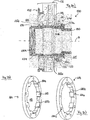
- FIG. 1 shows FIG. 1 in the sub-illustrations 1a) to 1d) different views of a pinion assembly 10 according to a first embodiment of the invention, and in the partial illustrations 1e) to 1f) different views of a compared to the partial figures 1a) to 1d) slightly modified adapter,
- FIG. 2 2 shows in partial illustration 2 a) a sectional representation of a pinion arrangement 110 according to a second exemplary embodiment of the present invention with the associated driver, and in the partial illustrations 2 b) and 2 c) two perspective views of a slightly opposite partial illustration 2a) modified adapter, and
- FIG. 3 shows in the partial illustrations 3a) to 3d) different views of a pinion assembly 210 according to a third embodiment of the invention and in the partial illustrations 3e) to 3h) different views of belonging to this pinion assembly adapter.
- FIG. 1 a shows a plan view of essential sections of a pinion arrangement 10 according to the invention, which comprises a pinion 12 with a central opening 11 and an external toothing, not shown in figures for reasons of space, and an adapter 14 rotatably mounted on the pinion 12.
- Part of Figure 1b) shows a plan view of the side of the pinion assembly 10, which faces away from the viewer in Figure 1a).
- the adapter 14 is substantially annular. It has inside a central opening 13, at the edge 13b a plurality of driver elements 15 are provided in the form of substantially annular segment, projecting engagement teeth extending from the edge 13b of the central opening 13 of the adapter 14 radially inwardly and to serve to transmit torque from the pinion 12 connected to the adapter 14 to a driver, not shown in the figures on a rear hub of a bicycle.
- This driver has in the usual way on its outer circumference driver elements which engage between the driver elements 15 of the adapter 14 for torque transmission.
- the radius 13r of the central opening 13 of the adapter 14 as a function of the angle about the axis of rotation A of the pinion assembly 10 alternately assumes its minimum value 13rmin (to the Drivers 15) and its maximum value 13rmax (between adjacent drivers 15).
- the pinion 12 is a conventional pinion of a pinion assembly for the rear wheel hub of a bicycle, for which details such as the exact shape or external toothing of the pinion 12 are not shown in the figures.
- essentially the proximal end sections of a plurality of connecting arms 19 can be seen, which extend in a known manner from an inner ring 18 of the pinion 12 obliquely outwards.
- the radius 11r and thus also the minimum radius 11rmin of the central opening 11 of the pinion 12 is smaller than the maximum radius 13rmax of the central opening 13 of the adapter 14, ie as the radius 13r of the central opening 13 of the adapter 14 between adjacent drivers 15th
- radial Fixing projections 17 are provided which are substantially circular in plan view, and of which axial projections 14v (see. Fig. 1b )) of the adapter 14 in the plane of the FIG. 1a ) extend into it.
- circular recesses 17d are provided on the surface of the fastening projections 17 visible in partial image 1a), the outline of which corresponds to the cross section of the projections 14v in a sectional plane perpendicular to the axis of rotation A.
- these depressions do not have to be present.
- the pinion 12 has the projections 14v corresponding axial recesses or through holes 12o, which serve to receive the axial projections 14v of the adapter 14 and so adapter 14 and pinion 12 rotatably connected to each other.
- the adapter 14 is pressed onto the pinion 12.
- the recesses 12o of the pinion 12 are formed as through holes in the present example, the axial projections 14v of the adapter 14 accommodated therein are accessible from the side of the pinion facing away from the adapter 12 in the partial image 1b) and can thus be accessed from this side, if desired are pushed out of the through holes 12o out to 14 and pinion 12 again to solve each other.
- Figures 1c) and 1d) show various perspective views of the article of Figures 1a) and 1b). It should be noted that the fact that the edge 11b of the central opening 11 of the pinion 12 according to the invention protrudes further inward than the regions of the edge 13b of the central opening 13 of the adapter 14 between adjacent drivers 15 only on the basis of the chosen perspective and the size relationships , is difficult or impossible to recognize in these partial pictures.
- the radius assumes its minimum value only at a few selected points, at which point the pinion then rests on the driver elements of the driver or is supported radially.
- the radius of the central opening of the pinion thereby assumes according to the invention at least three different locations or peripheral portions of its minimum value, which are preferably evenly distributed over the circumference.
- the adapter 114 is connected to the pinion 112 via separate pins 116 which are inserted into axial through holes 112o, 114o of the pinion 112 and the adapter 114.
- the pins 116 may be made of a material capable of doing so is to absorb high shear forces, such as steel.
- the adapter 114 can in turn be made of a relatively lightweight and inexpensive material.
- the adapter 114 with the exception of the axial openings 114 o, which are provided here instead of radial projections, in its outer shape substantially corresponds to the adapter 14 FIG. 1 ,
- the adapter 114 has the basic shape of a circular ring, on the outer circumference radial fastening projections 117 or fastening eyes are provided, in the middle of which the axial openings 114o are located, and on the inner circumference substantially annular segment-shaped driving elements 115 are provided, which extend radially inwardly.
- the pinion 112 is spaced by a spacer sleeve 121 of a further pinion 125 of the pinion assembly 110, which is the smallest pinion of in Fig. 2a ), while the pinion 112 represents the largest pinion of the pinion group 126.
- the individual pinions of the pinion group 126 may be rotatably connected to each other in any manner, such as pins, rivets or by a plurality of axially spaced pinions are integrally formed from a plate by punching and forming.
- Partial illustration 2a also shows an impeller 130 along whose outer circumference alternately spring sections are provided in the known manner as entrainment elements 132 and groove sections 134, each extending in the axial direction, the entrainment elements 132 of the drive 130 being formed between adjacent ones Driver elements 115 of the adapter 114 for torque transmission to intervene.
- the bicycle drive assembly formed from pinion assembly 110 and driver 130 the reference numeral 500 is given.
- the radial clearance between the driver 130 and pinion 112 is smaller than the radial clearance between the driver 130 and adapter 114, so that the radial centering of the pinion assembly 110 on the driver 130 also done here via the pinion 112.
- the radial distance between the driver elements 115 of the adapter 114 and the groove portions 134 of the driver 130 and between the edge 113b of the central opening 113 of the adapter 114 between adjacent driver elements 115 and the spring sections or driver elements 132 of the driver 130 is thus greater than the distance between the edge 111b of the (circular) opening 111 of the pinion 112 and the driver elements or spring sections 132 of the driver 130.
- the pinion group 126 and, if desired, further individual pinion or pinion groups can be fixed axially in a known manner between the flange portion 130a of the driver 130 shown on the right in FIG. 2a) and a closure screw (not shown) to be screwed into the internal thread 130t of the adapter 130.
- a plurality of recesses 212o are provided at the edge of the central opening 211 of the pinion 212, which can be slightly widened radially outwards and viewed both as radial recesses and as axial through openings or recesses.
- the external toothing of the conventionally a plurality of weight-reducing through holes 222 having pinion 212 is not shown for the sake of simplicity.
- the adapter 214 is in the form of a ring of alternating first and second peripheral sections 214.1, 214.2 in the circumferential direction (cf. 3e) to 3h ) formed in each case with the basic shape of circular ring segments, wherein in some sub-images indicated by dashed lines second peripheral portions 214.2 project radially beyond the first peripheral portions 214.1 and axially projecting to the side, the mounted state (part 3a) facing the pinion 212.
- the sections 214v of the second circumferential sections 214.2 which project axially beyond the first peripheral sections 214.1, are designed to engage in the recesses 212o of the pinion 212 and thus to connect the pinion 212 to the adapter 214 in a torque-proof manner.
- a special driver element 215.1 (see part illustration 3g)) can be made longer in the circumferential direction than the others.
- This special driver element 215.1 corresponds in a known manner a special groove portion of the drive not shown here and serves to position the pinion assembly 210 in a certain, predetermined angular position on the impeller.
- a special first peripheral section 214.1a is formed somewhat differently than the remaining first peripheral sections 214.1.
- the minimum radius 211rmin of the central opening 211r of the pinion 212 (assumed here at nine circumferentially distributed peripheral portions of the central opening 211) is smaller than the maximum radius 213rmax of the central opening 213 of the adapter 214, although in the figures Unfortunately, the size relationships are not easy to recognize.
- the recesses or recesses 212o on the pinion for the engagement elements 214v of the adapter 214 are dimensioned according to the surface pressure specification of the material used. The same applies to the axial extent of the radial engagement profile on the (not shown) impeller.
- the adapter ring 214 shown in the partial illustrations 3e) to 3h) can be produced in a particularly simple manner as a one-piece component by injection molding and be mounted by simply pushing or pressing on the pinion 212 thereto.
Description
Die vorliegende Erfindung betrifft eine Ritzelanordnung für einen Fahrrad-antrieb, umfassend: ein Ritzel mit einer zentralen Öffnung und einer Außenverzahnung, einen separat von dem Ritzel ausgebildeten Adapter, der dazu angepasst ist, drehfest mit dem Ritzel verbunden zu werden, und der eine zentrale Öffnung umfasst, an deren Rand mehrere Mitnehmerelemente vorgesehen sind, die sich von dem Rand der zentralen Öffnung des Adapters radial nach innen erstrecken und dazu ausgebildet sind, Drehmoment von dem mit dem Adapter verbundenen Ritzel auf einen Antreiber an einer Hinterradnabe eines Fahrrads zu übertragen.The present invention relates to a pinion assembly for a bicycle drive, comprising: a pinion having a central opening and an external toothing, an adapter formed separately from the pinion and adapted to be rotatably connected to the pinion, and a central opening comprises, at its edge a plurality of driver elements are provided, which extend from the edge of the central opening of the adapter radially inwardly and are adapted to transmit torque from the pinion connected to the adapter to a driver on a rear hub of a bicycle.
Eine derartige Ritzelanordnung ist beispielsweise aus der Druckschrift
Dies stellt hohe Anforderungen an die Fertigungsgenauigkeit für den Adapter, zumal dieser in axialer Richtung vorzugsweise deutlich breiter ausgebildet ist als das Ritzel, um eine möglichst große Kraft übertragende Fläche zu erzeugen, was wiederum die korrekte radiale Zentrierung erschwert. Dokument
Hierdurch kann zwar eine relativ genaue Zentrierung erreicht werden, aber die Breite der Mitnehmer-Elemente ist auf die Breite des Ritzels beschränkt, so dass die Kraft übertragende Fläche verhältnismäßig klein ist.In this way, although a relatively accurate centering can be achieved, but the width of the driver elements is limited to the width of the pinion, so that the force transmitting surface is relatively small.
Dies hat speziell bei der Materialpaarung von einem Ritzel aus Stahl und einem Antreiber aus Aluminium unter Umständen ein Eingraben des Ritzels in den Antreiber zur Folge, was den Antreiber zerstören und die Montage bzw. Demontage der Ritzelanordnung und des Antreibers erschweren kann.This may result in digging of the pinion into the impeller, especially in the pairing of a steel pinion and an aluminum impeller, which may destroy the impeller and make it difficult to assemble or disassemble the pinion assembly and the impeller.
Bei Ritzel-Kassetten, die auf einem bestimmten Typ von Antreiber (etwa einem XD-Antreiber) genutzt werden, werden darüber hinaus die Kräfte und die daraus resultierenden Drehmomente sämtlicher Ritzel über nur ein einziges Abschlussritzel und somit nur an einer einzigen Stelle in den Antreiber eingeleitet, was die oben erläuterte Problematik noch verstärkt.Moreover, with pinion cassettes used on a particular type of driver (such as an XD driver), the forces and resulting torques of all the pinions are introduced into the driver via only a single end pinion and thus only at a single location , which reinforces the problem explained above.
Bedingt durch das Fertigungsverfahren weisen viele Antreiber zusätzlich einen Freistich am axialen Anschlag auf. Dies führt dazu, dass insbesondere das letzte (größte) Ritzel, also das Abschlussritzel, zusätzlich an Überdeckungsfläche mit dem Antreiber verliert.Due to the manufacturing process, many impellers additionally have an undercut on the axial stop. This means that in particular the last (largest) pinion, so the end pinion, in addition loses coverage area with the impeller.
Gemeinsam ist den beiden oben erwähnten, aus dem Stand der Technik bekannten Ritzelanordnungen, dass die Mitnehmer-Elemente jeweils sowohl zur radialen Zentrierung der Ritzelanordnung auf dem Antreiber als auch zur Übertragung von Drehmoment von der Ritzelanordnung auf den Antreiber dienen.Common to the two above-mentioned, known from the prior art sprocket assemblies that the driver elements each serve both for radial centering of the pinion assembly on the impeller and for transmitting torque from the pinion assembly to the impeller.
Vor diesem Hintergrund besteht die Aufgabe des der vorliegenden Erfindung darin, die aus dem Stand der Technik bekannte Ritzelanordnung so weiter zu entwickeln, dass die radiale Zentrierung verbessert wird, ohne die Drehmoment-Übertragung dabei merklich zu verschlechtern.Against this background, the object of the present invention is to further develop the known from the prior art pinion assembly so that the radial centering is improved without worsening the torque transmission thereby noticeably.
Hierzu ist erfindungsgemäß vorgesehen, dass der minimale Radius der zentralen Öffnung des Ritzels kleiner ist als der maximale Radius der zentralen Öffnung des Adapters, wobei der Radius der zentralen Öffnung des Ritzels an wenigstens drei über den Umfang verteilen Stellen, vorzugsweise über den gesamten Umfang, seinen Minimalwert annimmt.For this purpose, the invention provides that the minimum radius of central opening of the pinion is smaller than the maximum radius of the central opening of the adapter, wherein the radius of the central opening of the pinion assumes at least three circumferentially distributed locations, preferably over the entire circumference, its minimum value.
Hierdurch werden die Voraussetzungen dafür geschaffen, dass dann, wenn Ritzel und Adapter auf den Antreiber aufgesetzt sind, das radiale Spiel zwischen Antreiber und Ritzel kleiner ist als das radiale Spiel zwischen Antreiber und Adapter. Damit erfolgt die Zentrierung der Ritzelanordnung auf dem Antreiber erfindungsgemäß über das Innenprofil des Ritzels, während die Drehmoment-Übertragung weiterhin über die Mitnehmer-Elemente des Adapters erfolgt. Die Funktionen "Kraft bzw. Drehmoment übertragen" und "Ritzel zentrieren" werden also auf zwei separate Bauteile verteilt.As a result, the conditions are created so that when pinion and adapter are placed on the driver, the radial clearance between the driver and pinion is smaller than the radial clearance between the driver and adapter. Thus, the centering of the pinion assembly on the impeller according to the invention via the inner profile of the pinion, while the torque transmission continues via the driver elements of the adapter. The functions "transmit force or torque" and "pinion centering" are thus distributed over two separate components.
Diese Funktionsteilung erleichtert die Herstellung der Einzelkomponenten. Durch die Entkopplung der Funktionen wird aufgrund der besseren Zentrierung der Rundlauf der Ritzel auf dem Antreiber verbessert. Des Weiteren limitiert die axiale Ausdehnung des Ritzels am Antreiber nicht mehr, wie noch in der
Erfindungsgemäß werden Adapter und Ritzel drehfest miteinander verbunden. Diese Verbindung dient primär der Übertragung des Drehmoments von dem Ritzel auf den Adapter, da die Radialkräfte über die Zentrierung am Innenprofil des Ritzels abgestützt werden. Prinzipiell gibt es diverse verschiedene Möglichkeiten der drehfesten Verbindung, etwa Vorsprünge, Stifte, umgebogene Arme oder ein sonstiger Form-, Kraft- oder Stoffschluss.According to the adapter and pinion rotatably connected to each other. This connection serves primarily to transmit the torque from the pinion to the adapter, since the radial forces are supported via the centering on the inner profile of the pinion. In principle, there are various different possibilities of non-rotatable connection, such as projections, pins, bent arms or any other form, force or material connection.
Bevorzugt ist vorgesehen, dass das Ritzel aus einem Material hergestellt ist, welches härter ist als das Material des Adapters. Besonders bevorzugt weist dabei das Material des Adapters eine Härte auf, die nicht größer ist als die des Antreibers. Sollte es also bei einer zu großer Kraftübertragung zu einem Eingraben des härteren in das weichere Material kommen, so wird hierdurch nicht der Antreiber sondern höchstens der Adapter beschädigt, der leichter ausgetauscht und kostengünstiger hergestellt werden kann als der Antreiber.It is preferably provided that the pinion is made of a material, Which is harder than the material of the adapter. Particularly preferably, the material of the adapter has a hardness which is not greater than that of the driver. Should it come to a burial of the harder in the softer material at a large power transmission, it will not damage the driver but at most the adapter, which can be easily replaced and made cheaper than the impeller.
Kostengünstig und einfach kann der Adapter aus Aluminium oder glasfaserverstärktem Kunststoff (GFK) hergestellt werden, vorzugsweise im Spritzgussverfahren.Inexpensive and simple, the adapter can be made of aluminum or glass fiber reinforced plastic (GRP), preferably by injection molding.
Der Adapter und das Ritzel können beispielsweise dadurch drehfest miteinander verbunden werden, dass ein Element aus dem Adapter und dem Ritzel, vorzugsweise das Ritzel, eine Mehrzahl von axialen Ausnehmungen umfasst, und das andere Element, vorzugsweise der Adapter, eine Mehrzahl von axialen Vorsprüngen umfasst, die dazu ausgebildet sind, in die axialen Ausnehmungen einzugreifen, vorzugsweise mit einer Presspassung.The adapter and the pinion may, for example, be non-rotatably connected to one another in that one element of the adapter and the pinion, preferably the pinion, comprises a plurality of axial recesses, and the other element, preferably the adapter, comprises a plurality of axial projections, which are adapted to engage in the axial recesses, preferably with a press fit.
Dabei sind die axialen Ausnehmungen vorzugsweise als axiale Durchgangsöffnungen ausgebildet, die das entsprechende Element vollständig durchqueren, denn auf diese Weise sind die axialen Vorsprünge des einen Elements, die in den Durchgangsöffnungen des anderen Elements aufgenommen sind, von der Seite des anderen Elements aus zugänglich, die dem einen Element abgewandt ist, und indem Druck von dieser Seite aus auf die axialen Vorsprünge ausgeübt wird, können die beiden aneinander montierten Elemente einfach wieder voneinander gelöst werden.The axial recesses are preferably formed as axial through holes that pass completely through the corresponding element, because in this way the axial projections of one element, which are received in the through holes of the other element, accessible from the side of the other element, the is facing away from the one element, and by exerting pressure from this side on the axial projections, the two elements mounted together can be easily detached from each other again.
Alternativ kann vorgesehen sein, dass der Adapter und das Ritzel jeweils eine Mehrzahl von axialen Ausnehmungen umfassen, wobei die Ritzelanordnung weiter eine Mehrzahl von Stiften, vorzugsweise Stahlstiften, umfasst, die in die axialen Ausnehmungen von dem Adapter und dem Ritzel eingesetzt, vorzugsweise eingepresst sind, so dass die Stifte den Adapter und das Ritzel drehfest miteinander verbinden.Alternatively it can be provided that the adapter and the pinion each comprise a plurality of axial recesses, wherein the pinion assembly further comprises a plurality of pins, preferably steel pins, which are inserted into the axial recesses of the adapter and the pinion, preferably pressed, so that the pins rotatably connect the adapter and the pinion with each other.
Diese Lösung weist Vorteile bezüglich des Gewichts auf, da die im Betrieb auftretenden Scherkräfte von den Stahlstiften problemlos aufgenommen werden, der Adapter jedoch aus einem leichteren Material, etwa Aluminium, gefertigt werden kann. Die Abwesenheit von Vorsprüngen in Ritzel und Adapter, also die im Verhältnis einfache, "zweidimensionale" Geometrie ermöglicht kostengünstige Fertigungsverfahren, etwa Extrudieren oder Stanzen.This solution has advantages in terms of weight, since the shear forces occurring during operation are easily absorbed by the steel pins, but the adapter can be made of a lighter material, such as aluminum. The absence of projections in pinion and adapter, so the relatively simple, "two-dimensional" geometry allows cost-effective manufacturing processes, such as extrusion or stamping.
Gemäß einer weiteren bevorzugten Ausführungsform kann vorgesehen sein, dass am Rand der zentralen Öffnung des Ritzels eine Mehrzahl von Ausnehmungen vorgesehen sind, und dass der Adapter als Ring aus einander in Umfangsrichtung abwechselnden ersten und zweiten Umfangsabschnitten mit der Grundform von Kreisring-Segmenten ausgebildet ist, wobei die zweiten Umfangsabschnitte die ersten Umfangsabschnitte radial nach innen überragen und axial zu einer Seite hin überragen, die im montierten Zustand dem Ritzel zugewandt ist.According to a further preferred embodiment it can be provided that at the edge of the central opening of the pinion a plurality of recesses are provided, and that the adapter is formed as a ring of mutually circumferentially alternating first and second peripheral portions with the basic shape of circular ring segments, wherein the second peripheral portions project radially inwardly beyond the first peripheral portions and protrude axially toward a side facing the pinion in the mounted state.
Dabei bilden diejenigen Abschnitte der zweiten Umfangsabschnitte, welche die ersten Umfangsabschnitte radial nach innen überragen, die Mitnehmer-Elemente des Adapters, und diejenigen Abschnitte der zweiten Umfangsabschnitte, welche die ersten Umfangsabschnitte axial überragen, sind dazu ausgebildet, in die Ausnehmungen des Ritzels einzugreifen und damit das Ritzel drehfest am Adapter zu montieren. Ein solcher Adapter kann besonders einfach im Spritzgussverfahren hergestellt werden und ermöglicht weiterhin eine gute Drehmoment-Übertragung von dem Ritzel auf den Adapter.In this case, those portions of the second peripheral portions, which project radially inwardly beyond the first circumferential portions, form the driver elements of the adapter, and those portions of the second circumferential portions which axially project beyond the first circumferential portions are adapted to engage in the recesses of the pinion and thus the pinion rotatably mounted on the adapter. Such an adapter can be produced particularly easily by injection molding and furthermore enables a good torque transmission from the pinion to the adapter.
Schließlich wird auch Schutz beantragt für eine Antriebsanordnung für ein Fahrrad, umfassend eine Ritzelanordnung nach einem der vorhergehenden Ansprüche und einen Antreiber mit mehreren Mitnehmer-Elementen, die dazu ausgebildet sind, in die Mitnehmer-Elemente des Adapters einzugreifen, um eine Drehmomentübertragung von dem Ritzel über den Adapter auf den Antreiber zu gewährleisten, wobei das radiale Spiel zwischen dem Antreiber und dem Ritzel kleiner ist als das radiale Spiel zwischen dem Antreiber und dem Adapter.Finally, protection is also sought for a drive assembly for a bicycle comprising a pinion assembly according to any one of the preceding claims and a driver having a plurality of cam elements adapted to engage the cam elements of the adapter to transfer torque from the pinion the adapter to ensure the impeller, wherein the radial clearance between the impeller and the pinion is smaller than the radial clearance between the impeller and the adapter.
Besonders bevorzugt kann hierbei vorgesehen sein, dass zwischen dem Ritzel und dem Antreiber eine Übergangspassung oder Presspassung vorliegt, während zwischen dem Adapter und dem Antreiber eine Spielpassung vorliegt.Particularly preferably, it can be provided that a transition fit or press fit exists between the pinion and the driver, while a clearance fit exists between the adapter and the driver.
Auch kann vorgesehen sein, dass zwischen Ritzel und Antreiber eine Presspassung, und zwischen Adapter und Antreiber eine Übergangspassung vorliegt.It can also be provided that there is a press fit between the pinion and the driver, and a transition fit between the adapter and the driver.
Es soll aber auch nicht ausgeschlossen sein, dass zwischen Ritzel und Antreiber sowie zwischen Adapter und Antreiber jeweils eine Übergangspassung oder auch eine Presspassung vorliegt, solange die Passung zwischen Ritzel und Antreiber fester ist als die zwischen Adapter und Antreiber.However, it should not be ruled out that there is a transition fit or an interference fit between the pinion and the driver and between the adapter and the driver, as long as the fit between the pinion and the driver is stronger than that between the adapter and the driver.
Nachfolgend wird die vorliegende Erfindung anhand von drei bevorzugten Ausführungsbeispielen erläutert, die in den beigefügten Figuren dargestellt sind.Hereinafter, the present invention will be explained with reference to three preferred embodiments shown in the accompanying drawings.
Dabei zeigt
Um die Figuren nicht zu überfrachten sind nicht immer alle Bestandteile mit Bezugszeichen gekennzeichnet, insbesondere wenn mehrere gleichartige Bestandteile in einer Figur vorhanden sind.In order not to overburden the figures, not all components are always identified by reference numerals, especially when several similar components are present in a figure.
Teilabbildung 1a) zeigt eine Draufsicht auf wesentliche Abschnitte einer erfindungsgemäßen Ritzelanordnung 10, die ein Ritzel 12 mit einer zentralen Öffnung 11 und einer in Figuren aus Platzgründen nicht dargestellten Außenverzahnung sowie einen an dem Ritzel 12 drehfest montierten Adapter 14 umfasst. Teilabbildung 1b) zeigt eine Draufsicht auf die Seite der Ritzelanordnung 10, die in Teilabbildung 1a) dem Betrachter abgewandt ist.1 a) shows a plan view of essential sections of a pinion arrangement 10 according to the invention, which comprises a
Der Adapter 14 ist im Wesentlichen ringförmig ausgebildet. Er weist im Inneren eine zentralen Öffnung 13 auf, an deren Rand 13b mehrere Mitnehmer-Elemente 15 in der Form von im Wesentlichen kreisringsegmentförmigen, vorstehenden Eingriffszähnen vorgesehen sind, die sich vom Rand 13b der zentralen Öffnung 13 des Adapters 14 radial nach innen erstrecken und dazu dienen, Drehmoment von dem mit dem Adapter 14 verbundenen Ritzel 12 auf einen in den Figuren nicht dargestellten Antreiber an einer Hinterradnabe eines Fahrrads zu übertragen. Dieser Antreiber weist in üblicher Weise an seinem Außenumfang Mitnehmer-Elemente auf, die zwischen die Mitnehmer-Elemente 15 des Adapters 14 zur Drehmoment-Übertragung eingreifen.The
Wie
Abgesehen von den nachfolgend beschriebenen Details insbesondere in Bezug auf Form und Größe der zentralen Öffnung 11 handelt es sich bei dem Ritzel 12 um ein konventionelles Ritzel einer Ritzelanordnung für die Hinterrad-Nabe eines Fahrrads, weswegen Details wie die genaue Gestalt oder die Außenverzahnung des Ritzels 12 in den Figuren nicht dargestellt sind. Es sind vorliegend im Wesentlichen die proximalen Endabschnitte mehrerer Verbindungsarme 19 zu erkennen, die sich in bekannter Weise von einem Innenring 18 des Ritzels 12 schräg nach außen erstrecken.Apart from the details described below, particularly with regard to the shape and size of the
Das Ritzel 12 weist im vorliegenden Ausführungsbeispiel eine zentrale Öffnung 11 auf, deren Radius 11r, wie aus der Draufsicht in Teilabbildung 1b) ersichtlich, über den gesamten Umfang der Öffnung 11 konstant ist und damit auch über den gesamten Umfang seinen Minimalwert 11rmin (=11r) annimmt.The
Wie in der Draufsicht in Teilabbildung 1a) besonders gut zu erkennen ist, ist der Radius 11r und damit auch der minimale Radius 11rmin der zentralen Öffnung 11 des Ritzels 12 kleiner als der maximale Radius 13rmax der zentralen Öffnung 13 des Adapters 14, also als der Radius 13r der zentralen Öffnung 13 des Adapters 14 zwischen benachbarten Mitnehmern 15.As can be seen particularly clearly in the plan view in FIG. 1a), the radius 11r and thus also the minimum radius 11rmin of the
Dies führt dazu, dass dann, wenn das Ritzel 12 und der daran drehfest montierte Adapter 14 auf den Antreiber aufgesetzt werden, die radiale Zentrierung der Ritzelanordnung 10 auf dem Antreiber über das Innenprofil des Ritzels 12 erfolgt, während eine Drehmomentübertragung über die Mitnehmer-Elemente 15 am Innenumfang von dem Adapter 14 umgesetzt wird.This results in that when the
Am Außenumfang des Adapters 14 sind mehrere (vorliegend sechs), gleichmäßig über den Umfang des Adapters 14 verteilte radiale Befestigungsvorsprünge 17 vorgesehen die in der Draufsicht im Wesentlichen kreisförmig sind, und von denen sich axiale Vorsprünge 14v (vgl.
Das Ritzel 12 weist den Vorsprüngen 14v entsprechende axiale Ausnehmungen oder Durchgangsöffnungen 12o auf, die dazu dienen, die axialen Vorsprünge 14v des Adapters 14 aufzunehmen und so Adapter 14 und Ritzel 12 drehfest miteinander zu verbinden. Vorzugsweise wird der Adapter 14 auf das Ritzel 12 aufgepresst.The
Da die Ausnehmungen 12o des Ritzels 12 im vorliegenden Beispiel als Durchgangsöffnungen ausgebildet sind, sind die darin aufgenommenen axialen Vorsprünge 14v des Adapters 14 von der in Teilabbildung 1b) sichtbaren, dem Adapter 12 abgewandten Seite des Ritzels aus zugänglich und können so gewünschtenfalls von dieser Seite aus aus den Durchgangsöffnungen 12o heraus gedrückt werden, um Adapter 14 und Ritzel 12 wieder voneinander zu lösen.Since the recesses 12o of the
Teilabbildungen 1c) und 1d) zeigen verschiedene perspektivische Ansichten des Gegenstands der Teilabbildungen 1a) und 1b). Es wird darauf hingewiesen, dass nur aufgrund der gewählten Perspektive und der Größenverhältnisse die Tatsache, dass der Rand 11b der zentralen Öffnung 11 des Ritzels 12 erfindungsgemäß weiter nach innen vorsteht als die Bereiche des Randes 13b der zentralen Öffnung 13 des Adapters 14 zwischen benachbarten Mitnehmern 15, in diesen Teilabbildungen nicht oder nur schwer zu erkennen ist.Figures 1c) and 1d) show various perspective views of the article of Figures 1a) and 1b). It should be noted that the fact that the
Teilabbildungen 1e) und 1f) zeigen einen gegenüber dem Adapter 14 der Teilabbildungen 1a) bis 1d) nur leicht modifizierten Adapter 14 eines modifizierten ersten Ausführungsbeispiels, für welches die gleichen Bezugszeichen verwendet werden wie für das erste Ausführungsbeispiel. Im Unterschied zu diesem ist in den Teilabbildungen 1e) und 1f) der Durchmesser der Vorsprünge 14v nicht kleiner als der sondern gleich dem Durchmesser der Befestigungsvorsprünge 17. Die axialen Ausnehmungen oder Durchgangsöffnungen des Ritzels sind natürlich entsprechend anzupassen.Teilabbildungen 1e) and 1f) show a relation to the
In
Bestandteile und Merkmale des zweiten und dritten Ausführungsbeispiels, die solchen des ersten Ausführungsbeispiels entsprechen, werden mit Bezugszeichen versehen, die aus den entsprechenden Bezugszeichen des ersten Ausführungsbeispiels durch Addition der Zahl 100 bzw. 200 hervorgehen. Die weiteren Ausführungsbeispiele werden in erster Linie nur insoweit ausführlich beschrieben, als sie sich vom ersten Ausführungsbeispiel unterscheiden, auf dessen vorstehende Beschreibung ansonsten verwiesen wird.Components and features of the second and third embodiments, which correspond to those of the first embodiment are provided with reference numerals, which emerge from the corresponding reference numerals of the first embodiment by adding the numbers 100 and 200, respectively. The other embodiments will be described in detail in the first place only insofar as they differ from the first embodiment, reference is otherwise made to the above description.
In dem in
Der Adapter 114 entspricht, mit Ausnahme der axialen Öffnungen 114o, die hier anstelle radialer Vorsprünge vorgesehen sind, in seiner äußeren Gestalt im Wesentlichen dem Adapter 14 aus
Wie die Teilabbildung 2a) zeigt, ist das Ritzel 112 über eine Distanzhülse 121 von einem weiteren Ritzel 125 der Ritzelanordnung 110 beabstandet, welches das kleinste Ritzel der in
Die einzelnen Ritzel der Ritzelgruppe 126 können in beliebiger Weise drehfest miteinander verbunden sein, etwa durch Stifte, Niete oder auch, indem mehrere axial beabstandete Ritzel einteilig aus einer Platte durch Stanzen und Umformen ausgebildet sind.The individual pinions of the
In Teilabbildung 2a) ist weiterhin auch ein Antreiber 130 dargestellt, längs dessen Außenumfang in bekannter Weise abwechselnd Federabschnitte als Mitnehmerelemente 132 und Nutabschnitte 134 vorgesehen sind, die sich jeweils in axialer Richtung erstrecken, wobei die Mitnehmerelemente 132 des Antreibers 130 dazu ausgebildet sind, zwischen benachbarte Mitnehmerelemente 115 des Adapters 114 zur Drehmoment-Übertragung einzugreifen.Partial illustration 2a) also shows an
Die aus Ritzelanordnung 110 und Antreiber 130 gebildete Fahrrad-Antriebsanordnung erhält das Bezugszeichen 500.The bicycle drive assembly formed from pinion assembly 110 and
Bei der Ritzelanordnung 110 ist vorgesehen (in der Darstellung allerdings nicht zu erkennen), dass das radiale Spiel zwischen Antreiber 130 und Ritzel 112 kleiner ist als das radiale Spiel zwischen Antreiber 130 und Adapter 114, so dass die radiale Zentrierung der Ritzelanordnung 110 auf dem Antreiber 130 auch hier über das Ritzel 112 erfolgt.In the pinion assembly 110 is provided (not shown in the illustration) that the radial clearance between the
Der radiale Abstand zwischen den Mitnehmerelementen 115 des Adapters 114 und den Nutabschnitten 134 des Antreibers 130 sowie zwischen dem Rand 113b der zentralen Öffnung 113 des Adapters 114 zwischen benachbarten Mitnehmerelementen 115 und den Federabschnitten bzw. Mitnehmerelementen 132 des Antreibers 130 ist also jeweils größer als der Abstand zwischen dem Rand 111b der (kreisförmigen) Öffnung 111 des Ritzels 112 und den Mitnehmerelementen bzw. Federabschnitten 132 des Antreibers 130.The radial distance between the driver elements 115 of the
Wenn die Stifte 116 auf der Seite des Ritzels 112, welche der Distanzhülse 121 zugewandt ist, (anders als in
Die Ritzelgruppe 126 sowie gewünschtenfalls weitere (nicht dargestellte) einzelne Ritzel oder Ritzelgruppen können in bekannter Weise zwischen dem rechts in Teilabbildung 2a) dargestellten Flanschabschnitt 130a des Antreibers 130 und einer in das Innengewinde 130t des Adapters 130 einzuschraubende (nicht dargestellte) Abschlussschraube axial fixiert werden.The
Der in den Teilabbildungen 2b) und 2d) dargestellte, gegenüber dem Adapter 114 aus Teilabbildung 2a) nur leicht modifizierte und daher mit den gleichen Bezugszeichen wie dieser versehene Adapter 114 unterscheidet sich von dem Adapter aus Teilabbildung 2a) im Wesentlichen dadurch, dass hier keine radial nach außen vorstehenden Befestigungsaugen vorgesehen sind, sondern die axialen Durchgangsöffnungen 114o in den kreisringförmigen Adapter 114 jeweils im Umfangsbereich der Mitnehmerelemente 115 eingebracht sind.The illustrated in the sub-images 2b) and 2d), compared to the
Hierbei sind am Rand der zentralen Öffnung 211 des Ritzels 212 eine Mehrzahl von Ausnehmungen 212o vorgesehen, die sich nach radial außen hin leicht erweitern und sowohl als radiale Ausnehmungen wie auch als axiale Durchgangsöffnungen oder Ausnehmungen angesehen werden können. Die Außenverzahnung des in üblicher Weise eine Mehrzahl von gewichtsreduzierenden Durchgangsöffnungen 222 aufweisenden Ritzels 212 ist aus Gründen der Einfachheit nicht dargestellt.In this case, a plurality of recesses 212o are provided at the edge of the
Der Adapter 214 ist als Ring aus einander in Umfangsrichtung abwechselnden ersten und zweiten Umfangsabschnitten 214.1, 214.2 (vgl.
Dabei fungieren diejenigen Abschnitte der zweiten Umfangsabschnitte 214.12, welche die ersten Umfangsabschnitte 214.1 radial nach innen überragen, als Mitnehmer-Elemente 215 des Adapters 214.In this case, those sections of the second circumferential sections 214.12, which project radially inwardly beyond the first peripheral sections 214.1, function as
Die Abschnitte 214v der zweiten Umfangsabschnitte 214.2, welche die ersten Umfangsabschnitte 214.1 axial überragen, sind dazu ausgebildet, in die Ausnehmungen 212o des Ritzels 212 einzugreifen und damit das Ritzel 212 drehfest mit dem Adapter 214 zu verbinden.The sections 214v of the second circumferential sections 214.2, which project axially beyond the first peripheral sections 214.1, are designed to engage in the recesses 212o of the
Ein spezielles Mitnehmerelement 215.1 (vgl. Teilabbildung 3g)) kann dabei in Umfangsrichtung länger ausgebildet sein als die anderen. Dieses spezielle Mitnehmerelement 215.1 entspricht in bekannter Weise einem speziellen Nutabschnitt des hier nicht dargestellten Antreibers und dient dazu, die Ritzelanordnung 210 in einer bestimmten, vorgegebenen Winkelstellung am Antreiber zu positionieren. Alternativ könnte man auch sagen, dass ein spezieller erster Umfangsabschnitt 214.1a etwas anders ausgebildet ist, als die übrigen ersten Umfangsabschnitte 214.1.A special driver element 215.1 (see part illustration 3g)) can be made longer in the circumferential direction than the others. This special driver element 215.1 corresponds in a known manner a special groove portion of the drive not shown here and serves to position the
Auch bei dem Ausführungsbeispiel aus
Die Ausnehmungen oder Aussparungen 212o am Ritzel für die Eingriffselemente 214v des Adapters 214 sind entsprechend der Flächenpressungsspezifikation des verwendeten Werkstoffs dimensioniert. Das Gleiche gilt für die axiale Ausdehnung des radialen Eingriffsprofils am (nicht dargestellten) Antreiber.The recesses or recesses 212o on the pinion for the engagement elements 214v of the
Der in den Teilabbildungen 3e) bis 3h) dargestellte Adapter-Ring 214 kann auf besonders einfache Weise als einteilig ausgebildetes Bauteil im Spritzgussverfahren hergestellt und durch einfaches Aufschieben bzw. Aufpressen auf das Ritzel 212 an diesem montiert werden.The
- Ritzelanordnung 10; 110; 210Pinion assembly 10; 110; 210
-
Ritzel 12; 112; 212
Pinion 12; 112; 212 -
zentrale Öffnung des Ritzels 11; 111; 211central opening of the
pinion 11; 111; 211 -
Rand der zentralen Öffnung des Ritzels 11b; 111b; 211bEdge of the central opening of the
pinion 11b; 111b; 211b -
Adapter 14; 114; 214
Adapter 14; 114; 214 - axialer Vorsprung des Adapters 14vaxial projection of the adapter 14v
-
zentrale Öffnung des Adapters 13; 113; 213central opening of the
adapter 13; 113; 213 -
Rand der zentralen Öffnung des Adapters 13b; 113b; 213bEdge of the central opening of the
adapter 13b; 113b; 213b - Radius der zentralen Öffnung des Adapters 13rRadius of the central opening of the adapter 13r
- minimaler Radius der zentralen Öffnung des Adapters 13rminminimum radius of the central opening of the adapter 13rmin
- maximaler Radius der zentralen Öffnung des Adapters 13rmaxmaximum radius of the central opening of the adapter 13rmax
-
Mitnehmer-Elemente des Adapters 15; 115; 215Carrier elements of the
adapter 15; 115; 215 - Rotationsachse der Ritzelanordnung ARotation axis of the pinion assembly A
-
Befestigungsvorsprung bzw. Befestigungsauge 17; 117Fastening projection or
fastening eye 17; 117 -
Vertiefung im Befestigungsvorsprung 17dRecess in the
fastening projection 17d -
Innenring des Ritzels 18Inner ring of the
pinion 18 -
Verbindungsarm des Ritzels 19Connecting arm of the
pinion 19 - axiale Durchgangsöffnung bzw. Ausnehmung des Ritzels 12o; 112o; 212oaxial passage opening or recess of the pinion 12o; 112o; 212o
- axiale Durchgangsöffnung des Adapters 114oaxial passage opening of the adapter 114o
-
Stift 116
Pin 116 -
Distanzhülse 121
Spacer sleeve 121 -
weiteres Ritzel 125another
pinion 125 - Aussparung im weiteren Ritzel 125oRecess in the other pinion 125o
-
Ritzelgruppe 126
Pinion group 126 -
Antreiber 130
Impeller 130 -
Flanschabschnitt des Antreibers 130aFlange portion of the
driver 130a - Innengewinde des Antreibers 130tInternal thread of the driver 130t
- Federabschnitt bzw. Mitnehmerelement des Antreibers 132Spring section or driver element of the driver 132nd
-
Nutabschnitt des Antreibers 134Groove portion of the
driver 134 -
gewichtsreduzierende Durchgangsöffnung 222weight reducing
passage opening 222 - erster Umfangsabschnitt des Adapters 214.1first peripheral portion of the adapter 214.1
- zweiter Umfangsabschnitt des Adapters 214.2second peripheral portion of the adapter 214.2
- spezielles Mitnehmerelement 215.aspecial driver element 215.a
- spezieller erster Umfangsabschnitt 214.1aspecial first peripheral portion 214.1a
Claims (8)
- Pinion arrangement (10; 110; 210) for a bicycle drive, comprising:a pinion (12; 112; 212) with a central opening (11; 111; 211) and an external toothing system,an adapter (14; 114; 214) which is configured separately from the pinion (12; 112; 212), is adapted to be connected fixedly to the pinion (12; 112; 212) so as to rotate with it, and comprises a central opening (13; 113; 213), on the edge (13b; 113b; 213b) of which a plurality of cam elements (15; 115; 215) are provided which extend from the edge (13b; 113b; 213b) of the central opening (13; 113; 213) of the adapter (14; 114; 214) radially to the inside and are configured to transmit torque from the pinion (12; 112; 212) which is connected to the adapter (14; 114; 214) to a driver on a rear wheel hub of a bicycle,characterized in that the minimum radius (11rmin; 211rmin) of the central opening (11; 111; 211) of the pinion (12; 112; 212) is smaller than the maximum radius (13rmax; 213rmax) of the central opening (13; 113; 213) of the adapter (14; 114; 214), the radius (11r) of the central opening (11; 111; 211) of the pinion (12; 112; 212) assuming its minimum value (11rmin; 211rmin) at at least three circumferential sections or points distributed over the circumference, preferably over the entire circumference.
- Pinion arrangement (10; 110; 210) according to Claim 1, characterized in that the pinion (12; 112; 212) is produced from a material which is harder than the material of the adapter (14; 114; 214).
- Pinion arrangement (10; 110; 210) according to Claim 1 or 2, characterized in that the adapter (14; 114; 214) is produced from aluminium or GFRP, preferably using the injection moulding process.
- Pinion arrangement (10; 210) according to one of the preceding claims, characterized in that one element (12, 14; 212; 214) from the adapter (14; 214) and the pinion (12; 212) comprises a plurality of axial recesses (12o; 212o), and the other element (14, 12; 214, 212) comprises a plurality of axial projections (14v; 214v) which are configured to engage into the axial recesses (12o; 212o), preferably with an interference fit, the axial recesses (12o; 212o) preferably being configured as axial through openings.
- Pinion arrangement (110) according to Claim 1, characterized in that the adapter (114) and the pinion (112) in each case comprise a plurality of axial recesses (112o, 114o), the pinion arrangement (110) comprising, furthermore, a plurality of pins (116), preferably steel pins, which are inserted, preferably pressed, into the axial recesses (112o, 114o) of the adapter (114) and the pinion (112), with the result that the pins (116) connect the adapter (114) and the pinion (112) fixedly to one another so as to rotate together.
- Pinion arrangement (210) according to Claim 1, characterized in that a plurality of recesses (212o) are provided at the edge of the central opening (211) of the pinion (212), and in that the adapter (214) is configured as a ring comprising first and second circumferential sections (214.1, 214.2) with the basic shape of circular ring segments which alternate with one another in the circumferential direction, the second circumferential sections (214.2) protruding radially inwards beyond the first circumferential sections (214.1) and protruding axially towards a side of the adapter (214), which side faces the pinion (212) in the state, in which it is fastened to the pinion (212), those sections of the second circumferential sections (214.2) which protrude radially inwards beyond the first circumferential sections (214.1) forming the cam elements (215) of the adapter (214), and those sections (214v) of the second circumferential sections (214.2) which protrude axially beyond the first circumferential sections (214.1) being configured to engage into the recesses (214o) of the pinion (214).
- Drive arrangement (500) for a bicycle, comprising a pinion arrangement (10; 110; 220) according to one of the preceding claims and a driver (130) with a plurality of cam elements (132) which are configured to engage between the cam elements (15; 115; 215) of the adapter, in order to ensure a torque transmission from the pinion (12; 112; 212) via the adapter (14; 114; 214) to the driver (130), the radial play between the driver (130) and the pinion (12; 112; 212) being smaller than the radial play between the driver (130) and the adapter (14; 114; 214).
- Drive arrangement (500) according to Claim 7, characterized in that there is a transition fit or interference fit between the pinion (12; 112; 212) and the driver, whereas there is a clearance fit between the adapter (14; 114; 214) and the driver.
Applications Claiming Priority (1)
| Application Number | Priority Date | Filing Date | Title |
|---|---|---|---|
| DE102015203709.6A DE102015203709A1 (en) | 2015-03-02 | 2015-03-02 | Pinion arrangement with adapter |
Publications (2)
| Publication Number | Publication Date |
|---|---|
| EP3064425A1 EP3064425A1 (en) | 2016-09-07 |
| EP3064425B1 true EP3064425B1 (en) | 2017-09-13 |
Family
ID=55446566
Family Applications (1)
| Application Number | Title | Priority Date | Filing Date |
|---|---|---|---|
| EP16000307.5A Active EP3064425B1 (en) | 2015-03-02 | 2016-02-06 | Pinion assembly with adapter |
Country Status (5)
| Country | Link |
|---|---|
| US (1) | US10151378B2 (en) |
| EP (1) | EP3064425B1 (en) |
| CN (1) | CN105936321B (en) |
| DE (1) | DE102015203709A1 (en) |
| TW (1) | TWI689443B (en) |
Cited By (2)
| Publication number | Priority date | Publication date | Assignee | Title |
|---|---|---|---|---|
| DE102019002638A1 (en) * | 2019-04-10 | 2020-10-15 | Sram Deutschland Gmbh | Torque transfer assembly for a bicycle |
| DE102020201889A1 (en) | 2020-02-14 | 2021-08-19 | Sram Deutschland Gmbh | Pinion for a bicycle drive |
Families Citing this family (5)
| Publication number | Priority date | Publication date | Assignee | Title |
|---|---|---|---|---|
| US10584786B2 (en) * | 2017-03-29 | 2020-03-10 | Shimano Inc. | Bicycle sprocket assembly |
| USD892587S1 (en) * | 2018-08-23 | 2020-08-11 | Albertson Enterprises, Llc | Wrench socket holder |
| IT201900013287A1 (en) * | 2019-07-30 | 2021-01-30 | Campagnolo Srl | Adapter for a sprocket body for a bicycle rear wheel |
| US11591043B2 (en) | 2019-07-30 | 2023-02-28 | Campagnolo S.R.L. | Sprocket-carrying body and sub-assembly of sprocket-carrying body and cogset for a bicycle rear wheel |
| USD959337S1 (en) * | 2020-11-17 | 2022-08-02 | Gates Corporation | Spokes for sprocket |
Family Cites Families (56)
| Publication number | Priority date | Publication date | Assignee | Title |
|---|---|---|---|---|
| US3191735A (en) * | 1963-02-28 | 1965-06-29 | Borg Warner | Spline liner |
| FR2602841B1 (en) * | 1986-08-05 | 1990-11-23 | Maillard Maurice Ets | BICYCLE FREE WHEEL CROWN, METHOD FOR FIXING PINIONS ON SUCH A CROWN AND FREE WHEEL THUS OBTAINED |
| IT1245431B (en) * | 1991-03-04 | 1994-09-20 | Campagnolo Srl | CRANK-GEAR GROUP FOR A BICYCLE |
| JPH04297390A (en) * | 1991-03-27 | 1992-10-21 | Shimano Inc | Multistage wheel for bicycle rear wheel |
| FI952907A (en) * | 1994-06-14 | 1995-12-15 | Mbi Co Ltd | Device for driving a bicycle forward |
| US5503600A (en) * | 1994-11-17 | 1996-04-02 | Kaynar Technologies, Inc. | Derailleur gear assembly |
| IT1289715B1 (en) * | 1996-12-05 | 1998-10-16 | Campagnolo Srl | PINION SUPPORT GROUP FOR A BICYCLE |
| KR100195515B1 (en) * | 1996-12-30 | 1999-06-15 | 마재열 | Forward driving apparatus' control device for bycyle |
| US6428437B1 (en) * | 1999-06-10 | 2002-08-06 | Raphael Schlanger | Power transmission assembly |
| US7011592B2 (en) * | 2002-03-08 | 2006-03-14 | Shimano, Inc. | Sprocket assembly for a bicycle |
| EP1407962A1 (en) * | 2002-10-11 | 2004-04-14 | Campagnolo Srl | Sprocket support member for a bicycle sprocket assembly |
| DE10260565B4 (en) * | 2002-12-21 | 2016-09-15 | Sram Deutschland Gmbh | The sprocket assembly |
| US6866604B2 (en) * | 2003-01-17 | 2005-03-15 | Shimano, Inc. | Multiple level sprocket support for a bicycle |
| US7044876B2 (en) * | 2003-01-17 | 2006-05-16 | Shimano, Inc. | Bicycle sprocket having lateral protrusions for use in a multiple sprocket assembly |
| JP2005029072A (en) * | 2003-07-09 | 2005-02-03 | Shimano Inc | Outer for bicycle hub and bicycle hub |
| DE102004027963B4 (en) * | 2004-06-08 | 2015-12-24 | Sram Deutschland Gmbh | Riveted sprocket set |
| EP1616781A1 (en) * | 2004-07-15 | 2006-01-18 | Campagnolo S.R.L. | Sprocket-carrying body for the rear wheel of a bicycle |
| US7585240B2 (en) * | 2005-02-03 | 2009-09-08 | Shimano Inc. | Bicycle sprocket assembly |
| US7435197B2 (en) * | 2005-05-11 | 2008-10-14 | Shimano Inc. | Rear sprocket for bicycle transmission |
| US7959529B2 (en) * | 2007-03-21 | 2011-06-14 | Sram, Llc | Bicycle multi-gear cassette |
| US9150280B2 (en) * | 2007-03-21 | 2015-10-06 | Sram, Llc | Bicycle multi-gear cassette |
| TW200900323A (en) * | 2007-06-19 | 2009-01-01 | William Blair Shook | Steel insert for aluminum spline body |
| ITMI20071221A1 (en) * | 2007-06-19 | 2008-12-20 | Campagnolo Srl | ASSEMBLY OF PEDIVELLA AND RELATIVE CRANKCASE AND ELEMENT FOR TORQUE TRANSMISSION FROM CRANK TO A BICYCLE CHAIN |
| US8371660B2 (en) * | 2007-06-19 | 2013-02-12 | William B. Shook | Load transmitting insert for a soft spline body |
| ITMI20071658A1 (en) * | 2007-08-09 | 2009-02-10 | Campagnolo Srl | PINION MODULE FOR A BICYCLE AND SPROCKET PACK INCLUDING THIS MODULE |
| ITMI20071659A1 (en) * | 2007-08-09 | 2009-02-10 | Campagnolo Srl | SPROCKET ASSEMBLY FOR A REAR BICYCLE WHEEL AND SPROCKET PACK INCLUDING SUCH ASSEMBLY |
| ITMI20071661A1 (en) * | 2007-08-09 | 2009-02-10 | Campagnolo Srl | ASSEEME OF WHEELS TOOTHED FOR A BICYCLE |
| US7871347B2 (en) * | 2007-10-11 | 2011-01-18 | Shimano Inc. | Bicycle rear sprocket assembly |
| TWM331451U (en) * | 2007-11-09 | 2008-05-01 | Xero Engineering Inc | Protection structure of the gear sleeve of a hub |
| DE102008010903A1 (en) * | 2008-02-23 | 2009-08-27 | Sram Deutschland Gmbh | Weight-optimized multi-sprocket wheel for a bicycle |
| DE102009024455A1 (en) * | 2009-06-10 | 2011-01-05 | Audi Ag | Built-shaft element, in particular built camshaft for valve-controlled internal combustion engines |
| DE102010027228B4 (en) * | 2009-11-04 | 2021-12-09 | Sram Deutschland Gmbh | Multiple sprocket arrangement for bicycles |
| US9193416B2 (en) * | 2009-11-30 | 2015-11-24 | Shimano Inc. | Bicycle sprocket support assembly |
| TWI393641B (en) * | 2010-01-19 | 2013-04-21 | Joy Ind Co Ltd | Bicycle of the ratchet sleeve structure |
| WO2011090383A1 (en) * | 2010-01-21 | 2011-07-28 | Van Robertus Cornelius Wilhelmus Hoek | Sprocket mounting carrier for a bicycle |
| US20110193406A1 (en) * | 2010-02-09 | 2011-08-11 | Joy Industrial Co., Ltd. | Tubular portion of bicycle hub |
| US20120139327A1 (en) * | 2010-12-02 | 2012-06-07 | Ching-Shu Chen | Bicycle Hub Assembly |
| DE102010053597B4 (en) * | 2010-12-07 | 2021-12-02 | Sram Deutschland Gmbh | Multiple sprocket assembly for a bicycle |
| CN201971115U (en) * | 2011-01-05 | 2011-09-14 | 袁金谦 | Driving assembly for bicycle |
| US8905878B2 (en) * | 2011-01-28 | 2014-12-09 | Shimano (Singapore) Pte., Ltd. | Bicycle sprocket assembly |
| US8696503B2 (en) * | 2011-03-01 | 2014-04-15 | Shimano Inc. | Bicycle sprocket assembly |
| US8663044B2 (en) * | 2011-03-21 | 2014-03-04 | De-Hsin Lin | Sprocket assembly that is worked easily and quickly |
| US8968130B2 (en) * | 2011-03-23 | 2015-03-03 | Tien Hsin Industries Co., Ltd. | Bicycle cogset with support element |
| GB2490114B (en) * | 2011-04-18 | 2013-06-12 | Rolls Royce Plc | Rotational assembly |
| TWI585000B (en) * | 2011-07-13 | 2017-06-01 | Sram De Gmbh | A multi-sprocket equipped with a small sprocket is used for the transmission of the bicycle transmission |
| DE102011107162B4 (en) * | 2011-07-13 | 2024-02-22 | Sram Deutschland Gmbh | Multiple sprocket arrangement for a bicycle gear with small sprockets and an adapter for this |
| DE102012016608A1 (en) * | 2011-08-26 | 2013-02-28 | Dt Swiss Ag | Drive hub for e.g. racing vehicle, has sleeve unit that is provided with pinion which is arranged extending in radially outward manner and is spaced apart from axially spaced bearings so as to rotate shaft bearing |
| US8801109B2 (en) * | 2011-09-28 | 2014-08-12 | Kunshan Henry Metal Technology Co., Ltd. | Protection unit for driving socket of hub |
| CN202765219U (en) * | 2012-08-10 | 2013-03-06 | 台湾微转股份有限公司 | Bicycle chain wheel set |
| DE102012020563A1 (en) * | 2012-10-12 | 2014-04-17 | Sram Deutschland Gmbh | fastening device |
| US9533735B2 (en) * | 2013-07-19 | 2017-01-03 | Sram Deutschland Gmbh | Multiple-sprocket arrangement for a bicycle gearing |
| US20150133249A1 (en) * | 2013-11-08 | 2015-05-14 | Tien Hisn Industries Co., Ltd. | Bicycle drive chainwheel assembly |
| US9415835B2 (en) * | 2014-01-24 | 2016-08-16 | Shimano Inc. | Rotatable annular bicycle component and bicycle rear sprocket |
| US9297450B2 (en) * | 2014-04-02 | 2016-03-29 | Shimano Inc. | Bicycle rear sprocket |
| US9011282B2 (en) * | 2014-11-21 | 2015-04-21 | D3 Innovation Inc. | Bicycle sprocket for use with a multi-gear rear cassette |
| US9511819B1 (en) * | 2015-05-25 | 2016-12-06 | Shimano Inc. | Bicycle rear sprocket assembly |
-
2015
- 2015-03-02 DE DE102015203709.6A patent/DE102015203709A1/en not_active Withdrawn
-
2016
- 2016-02-06 EP EP16000307.5A patent/EP3064425B1/en active Active
- 2016-02-25 TW TW105105710A patent/TWI689443B/en active
- 2016-03-01 CN CN201610152361.7A patent/CN105936321B/en active Active
- 2016-03-02 US US15/058,653 patent/US10151378B2/en active Active
Non-Patent Citations (1)
| Title |
|---|
| None * |
Cited By (3)
| Publication number | Priority date | Publication date | Assignee | Title |
|---|---|---|---|---|
| DE102019002638A1 (en) * | 2019-04-10 | 2020-10-15 | Sram Deutschland Gmbh | Torque transfer assembly for a bicycle |
| EP3736201A1 (en) | 2019-04-10 | 2020-11-11 | SRAM Deutschland GmbH | Torque transmission module for a bicycle |
| DE102020201889A1 (en) | 2020-02-14 | 2021-08-19 | Sram Deutschland Gmbh | Pinion for a bicycle drive |
Also Published As
| Publication number | Publication date |
|---|---|
| TW201641357A (en) | 2016-12-01 |
| US10151378B2 (en) | 2018-12-11 |
| CN105936321B (en) | 2019-11-15 |
| US20160258523A1 (en) | 2016-09-08 |
| TWI689443B (en) | 2020-04-01 |
| DE102015203709A1 (en) | 2016-09-08 |
| CN105936321A (en) | 2016-09-14 |
| EP3064425A1 (en) | 2016-09-07 |
Similar Documents
| Publication | Publication Date | Title |
|---|---|---|
| EP3064425B1 (en) | Pinion assembly with adapter | |
| EP2612051B1 (en) | Transmitter with preassembled synchronizing rings | |
| DE102011101393B4 (en) | Stop buffer arrangement with a rotary adjustment mechanism and with a rotary locking mechanism and kit for a stop buffer arrangement | |
| EP2808582B1 (en) | Planetary gear of a motor vehicle actuator | |
| DE102016121748A1 (en) | Coupling device for a motorcycle | |
| DE102012102775B4 (en) | Helical gear for an electromechanical steering device | |
| DE3136470A1 (en) | "DIFFERENTIAL WITH TWO AXLE DRIVE SHAFTS" | |
| EP0501149A1 (en) | Fastening for securing a coupling sleeve | |
| EP3070361A1 (en) | Brake disk/hub assembly | |
| DE1291586B (en) | Differential gear with friction clutches | |
| DE10253451A1 (en) | Compound brake disk, comprising center piece provided with openings for insertion of projections located at friction ring stub | |
| EP3577012B1 (en) | Length-adjustable steering shaft for a motor vehicle, and profiled sleeve for a steering shaft | |
| DE102015102141B4 (en) | Transmitter for a manual transmission for a motor vehicle, assembly with transmitter, gear shaft and gear wheel and transmission | |
| DE102004008538B4 (en) | Differential with a bolt mounting assembly | |
| AT518787B1 (en) | gearing | |
| DE102009038735A1 (en) | Adjusting device for backrest of seat of motor vehicle, has brake unit cooperating with projection at backrest adapter and gearwheel, where axis center part of brake unit extends parallel to rotational axis | |
| DE102010002846B4 (en) | Torque transmission assembly, in particular for a vehicle drive train | |
| EP3064424B1 (en) | Chain wheel for a bicycle drive | |
| EP2834083B1 (en) | Wheel hub rotary joint arrangement | |
| EP3449148B1 (en) | Brake disc for a vehicle | |
| DE102015203283A1 (en) | Torque transmission device with tilting minimization in freewheeling unit | |
| DE102010036280B4 (en) | Transmitter for a synchronization assembly of a manual transmission | |
| DE102018205006A1 (en) | gear | |
| DE19929639B4 (en) | Shaft-hub connection with shaped bevels in shaft teeth | |
| EP3318774A1 (en) | Connection assembly for connecting a shaft to a component |
Legal Events
| Date | Code | Title | Description |
|---|---|---|---|
| PUAI | Public reference made under article 153(3) epc to a published international application that has entered the european phase |
Free format text: ORIGINAL CODE: 0009012 |
|
| AK | Designated contracting states |
Kind code of ref document: A1 Designated state(s): AL AT BE BG CH CY CZ DE DK EE ES FI FR GB GR HR HU IE IS IT LI LT LU LV MC MK MT NL NO PL PT RO RS SE SI SK SM TR |
|
| AX | Request for extension of the european patent |
Extension state: BA ME |
|
| 17P | Request for examination filed |
Effective date: 20160929 |
|
| GRAP | Despatch of communication of intention to grant a patent |
Free format text: ORIGINAL CODE: EPIDOSNIGR1 |
|
| INTG | Intention to grant announced |
Effective date: 20170424 |
|
| GRAS | Grant fee paid |
Free format text: ORIGINAL CODE: EPIDOSNIGR3 |
|
| GRAA | (expected) grant |
Free format text: ORIGINAL CODE: 0009210 |
|
| AK | Designated contracting states |
Kind code of ref document: B1 Designated state(s): AL AT BE BG CH CY CZ DE DK EE ES FI FR GB GR HR HU IE IS IT LI LT LU LV MC MK MT NL NO PL PT RO RS SE SI SK SM TR |
|
| REG | Reference to a national code |
Ref country code: GB Ref legal event code: FG4D Free format text: NOT ENGLISH |
|
| REG | Reference to a national code |
Ref country code: CH Ref legal event code: EP |
|
| REG | Reference to a national code |
Ref country code: IE Ref legal event code: FG4D Free format text: LANGUAGE OF EP DOCUMENT: GERMAN |
|
| REG | Reference to a national code |
Ref country code: AT Ref legal event code: REF Ref document number: 927840 Country of ref document: AT Kind code of ref document: T Effective date: 20171015 |
|
| REG | Reference to a national code |
Ref country code: DE Ref legal event code: R096 Ref document number: 502016000123 Country of ref document: DE |
|
| REG | Reference to a national code |
Ref country code: NL Ref legal event code: FP |
|
| REG | Reference to a national code |
Ref country code: LT Ref legal event code: MG4D |
|
| PG25 | Lapsed in a contracting state [announced via postgrant information from national office to epo] |
Ref country code: FI Free format text: LAPSE BECAUSE OF FAILURE TO SUBMIT A TRANSLATION OF THE DESCRIPTION OR TO PAY THE FEE WITHIN THE PRESCRIBED TIME-LIMIT Effective date: 20170913 Ref country code: HR Free format text: LAPSE BECAUSE OF FAILURE TO SUBMIT A TRANSLATION OF THE DESCRIPTION OR TO PAY THE FEE WITHIN THE PRESCRIBED TIME-LIMIT Effective date: 20170913 Ref country code: NO Free format text: LAPSE BECAUSE OF FAILURE TO SUBMIT A TRANSLATION OF THE DESCRIPTION OR TO PAY THE FEE WITHIN THE PRESCRIBED TIME-LIMIT Effective date: 20171213 Ref country code: SE Free format text: LAPSE BECAUSE OF FAILURE TO SUBMIT A TRANSLATION OF THE DESCRIPTION OR TO PAY THE FEE WITHIN THE PRESCRIBED TIME-LIMIT Effective date: 20170913 Ref country code: LT Free format text: LAPSE BECAUSE OF FAILURE TO SUBMIT A TRANSLATION OF THE DESCRIPTION OR TO PAY THE FEE WITHIN THE PRESCRIBED TIME-LIMIT Effective date: 20170913 |
|
| REG | Reference to a national code |
Ref country code: FR Ref legal event code: PLFP Year of fee payment: 3 |
|
| PG25 | Lapsed in a contracting state [announced via postgrant information from national office to epo] |
Ref country code: LV Free format text: LAPSE BECAUSE OF FAILURE TO SUBMIT A TRANSLATION OF THE DESCRIPTION OR TO PAY THE FEE WITHIN THE PRESCRIBED TIME-LIMIT Effective date: 20170913 Ref country code: BG Free format text: LAPSE BECAUSE OF FAILURE TO SUBMIT A TRANSLATION OF THE DESCRIPTION OR TO PAY THE FEE WITHIN THE PRESCRIBED TIME-LIMIT Effective date: 20171213 Ref country code: RS Free format text: LAPSE BECAUSE OF FAILURE TO SUBMIT A TRANSLATION OF THE DESCRIPTION OR TO PAY THE FEE WITHIN THE PRESCRIBED TIME-LIMIT Effective date: 20170913 Ref country code: ES Free format text: LAPSE BECAUSE OF FAILURE TO SUBMIT A TRANSLATION OF THE DESCRIPTION OR TO PAY THE FEE WITHIN THE PRESCRIBED TIME-LIMIT Effective date: 20170913 Ref country code: GR Free format text: LAPSE BECAUSE OF FAILURE TO SUBMIT A TRANSLATION OF THE DESCRIPTION OR TO PAY THE FEE WITHIN THE PRESCRIBED TIME-LIMIT Effective date: 20171214 |
|
| PG25 | Lapsed in a contracting state [announced via postgrant information from national office to epo] |
Ref country code: RO Free format text: LAPSE BECAUSE OF FAILURE TO SUBMIT A TRANSLATION OF THE DESCRIPTION OR TO PAY THE FEE WITHIN THE PRESCRIBED TIME-LIMIT Effective date: 20170913 Ref country code: PL Free format text: LAPSE BECAUSE OF FAILURE TO SUBMIT A TRANSLATION OF THE DESCRIPTION OR TO PAY THE FEE WITHIN THE PRESCRIBED TIME-LIMIT Effective date: 20170913 Ref country code: CZ Free format text: LAPSE BECAUSE OF FAILURE TO SUBMIT A TRANSLATION OF THE DESCRIPTION OR TO PAY THE FEE WITHIN THE PRESCRIBED TIME-LIMIT Effective date: 20170913 |
|
| PG25 | Lapsed in a contracting state [announced via postgrant information from national office to epo] |
Ref country code: EE Free format text: LAPSE BECAUSE OF FAILURE TO SUBMIT A TRANSLATION OF THE DESCRIPTION OR TO PAY THE FEE WITHIN THE PRESCRIBED TIME-LIMIT Effective date: 20170913 Ref country code: SM Free format text: LAPSE BECAUSE OF FAILURE TO SUBMIT A TRANSLATION OF THE DESCRIPTION OR TO PAY THE FEE WITHIN THE PRESCRIBED TIME-LIMIT Effective date: 20170913 Ref country code: IT Free format text: LAPSE BECAUSE OF FAILURE TO SUBMIT A TRANSLATION OF THE DESCRIPTION OR TO PAY THE FEE WITHIN THE PRESCRIBED TIME-LIMIT Effective date: 20170913 Ref country code: IS Free format text: LAPSE BECAUSE OF FAILURE TO SUBMIT A TRANSLATION OF THE DESCRIPTION OR TO PAY THE FEE WITHIN THE PRESCRIBED TIME-LIMIT Effective date: 20180113 Ref country code: SK Free format text: LAPSE BECAUSE OF FAILURE TO SUBMIT A TRANSLATION OF THE DESCRIPTION OR TO PAY THE FEE WITHIN THE PRESCRIBED TIME-LIMIT Effective date: 20170913 |
|
| REG | Reference to a national code |
Ref country code: DE Ref legal event code: R097 Ref document number: 502016000123 Country of ref document: DE |
|
| PLBE | No opposition filed within time limit |
Free format text: ORIGINAL CODE: 0009261 |
|
| STAA | Information on the status of an ep patent application or granted ep patent |
Free format text: STATUS: NO OPPOSITION FILED WITHIN TIME LIMIT |
|
| PG25 | Lapsed in a contracting state [announced via postgrant information from national office to epo] |
Ref country code: DK Free format text: LAPSE BECAUSE OF FAILURE TO SUBMIT A TRANSLATION OF THE DESCRIPTION OR TO PAY THE FEE WITHIN THE PRESCRIBED TIME-LIMIT Effective date: 20170913 |
|
| 26N | No opposition filed |
Effective date: 20180614 |
|
| PG25 | Lapsed in a contracting state [announced via postgrant information from national office to epo] |
Ref country code: MT Free format text: LAPSE BECAUSE OF FAILURE TO SUBMIT A TRANSLATION OF THE DESCRIPTION OR TO PAY THE FEE WITHIN THE PRESCRIBED TIME-LIMIT Effective date: 20170913 Ref country code: MC Free format text: LAPSE BECAUSE OF FAILURE TO SUBMIT A TRANSLATION OF THE DESCRIPTION OR TO PAY THE FEE WITHIN THE PRESCRIBED TIME-LIMIT Effective date: 20170913 |
|
| REG | Reference to a national code |
Ref country code: IE Ref legal event code: MM4A |
|
| REG | Reference to a national code |
Ref country code: BE Ref legal event code: MM Effective date: 20180228 |
|
| PG25 | Lapsed in a contracting state [announced via postgrant information from national office to epo] |
Ref country code: SI Free format text: LAPSE BECAUSE OF FAILURE TO SUBMIT A TRANSLATION OF THE DESCRIPTION OR TO PAY THE FEE WITHIN THE PRESCRIBED TIME-LIMIT Effective date: 20170913 Ref country code: LU Free format text: LAPSE BECAUSE OF NON-PAYMENT OF DUE FEES Effective date: 20180206 |
|
| PG25 | Lapsed in a contracting state [announced via postgrant information from national office to epo] |
Ref country code: IE Free format text: LAPSE BECAUSE OF NON-PAYMENT OF DUE FEES Effective date: 20180206 |
|
| PG25 | Lapsed in a contracting state [announced via postgrant information from national office to epo] |
Ref country code: BE Free format text: LAPSE BECAUSE OF NON-PAYMENT OF DUE FEES Effective date: 20180228 |
|
| REG | Reference to a national code |
Ref country code: CH Ref legal event code: PL |
|
| PG25 | Lapsed in a contracting state [announced via postgrant information from national office to epo] |
Ref country code: LI Free format text: LAPSE BECAUSE OF NON-PAYMENT OF DUE FEES Effective date: 20190228 Ref country code: CH Free format text: LAPSE BECAUSE OF NON-PAYMENT OF DUE FEES Effective date: 20190228 |
|
| PG25 | Lapsed in a contracting state [announced via postgrant information from national office to epo] |
Ref country code: TR Free format text: LAPSE BECAUSE OF FAILURE TO SUBMIT A TRANSLATION OF THE DESCRIPTION OR TO PAY THE FEE WITHIN THE PRESCRIBED TIME-LIMIT Effective date: 20170913 |
|
| PG25 | Lapsed in a contracting state [announced via postgrant information from national office to epo] |
Ref country code: PT Free format text: LAPSE BECAUSE OF FAILURE TO SUBMIT A TRANSLATION OF THE DESCRIPTION OR TO PAY THE FEE WITHIN THE PRESCRIBED TIME-LIMIT Effective date: 20170913 |
|
| PG25 | Lapsed in a contracting state [announced via postgrant information from national office to epo] |
Ref country code: CY Free format text: LAPSE BECAUSE OF FAILURE TO SUBMIT A TRANSLATION OF THE DESCRIPTION OR TO PAY THE FEE WITHIN THE PRESCRIBED TIME-LIMIT Effective date: 20170913 Ref country code: MK Free format text: LAPSE BECAUSE OF NON-PAYMENT OF DUE FEES Effective date: 20170913 Ref country code: HU Free format text: LAPSE BECAUSE OF FAILURE TO SUBMIT A TRANSLATION OF THE DESCRIPTION OR TO PAY THE FEE WITHIN THE PRESCRIBED TIME-LIMIT; INVALID AB INITIO Effective date: 20160206 |
|
| PG25 | Lapsed in a contracting state [announced via postgrant information from national office to epo] |
Ref country code: AL Free format text: LAPSE BECAUSE OF FAILURE TO SUBMIT A TRANSLATION OF THE DESCRIPTION OR TO PAY THE FEE WITHIN THE PRESCRIBED TIME-LIMIT Effective date: 20170913 |
|
| GBPC | Gb: european patent ceased through non-payment of renewal fee |
Effective date: 20200206 |
|
| PG25 | Lapsed in a contracting state [announced via postgrant information from national office to epo] |
Ref country code: GB Free format text: LAPSE BECAUSE OF NON-PAYMENT OF DUE FEES Effective date: 20200206 |
|
| REG | Reference to a national code |
Ref country code: AT Ref legal event code: MM01 Ref document number: 927840 Country of ref document: AT Kind code of ref document: T Effective date: 20210206 |
|
| PG25 | Lapsed in a contracting state [announced via postgrant information from national office to epo] |
Ref country code: AT Free format text: LAPSE BECAUSE OF NON-PAYMENT OF DUE FEES Effective date: 20210206 |
|
| PGFP | Annual fee paid to national office [announced via postgrant information from national office to epo] |
Ref country code: NL Payment date: 20230216 Year of fee payment: 8 |
|
| PGFP | Annual fee paid to national office [announced via postgrant information from national office to epo] |
Ref country code: FR Payment date: 20230221 Year of fee payment: 8 |
|
| PGFP | Annual fee paid to national office [announced via postgrant information from national office to epo] |
Ref country code: DE Payment date: 20230301 Year of fee payment: 8 |
|
| P01 | Opt-out of the competence of the unified patent court (upc) registered |
Effective date: 20230523 |
|
| PGFP | Annual fee paid to national office [announced via postgrant information from national office to epo] |
Ref country code: NL Payment date: 20240219 Year of fee payment: 9 |