EP3064408A1 - Dispositif de reglage de freinage de remorque - Google Patents
Dispositif de reglage de freinage de remorque Download PDFInfo
- Publication number
- EP3064408A1 EP3064408A1 EP16158783.7A EP16158783A EP3064408A1 EP 3064408 A1 EP3064408 A1 EP 3064408A1 EP 16158783 A EP16158783 A EP 16158783A EP 3064408 A1 EP3064408 A1 EP 3064408A1
- Authority
- EP
- European Patent Office
- Prior art keywords
- gap
- fact
- command
- channel
- communicating
- Prior art date
- Legal status (The legal status is an assumption and is not a legal conclusion. Google has not performed a legal analysis and makes no representation as to the accuracy of the status listed.)
- Granted
Links
- 239000012530 fluid Substances 0.000 claims abstract description 34
- 238000000926 separation method Methods 0.000 claims description 4
- 230000036316 preload Effects 0.000 description 1
- 230000000284 resting effect Effects 0.000 description 1
Images


Classifications
-
- B—PERFORMING OPERATIONS; TRANSPORTING
- B60—VEHICLES IN GENERAL
- B60T—VEHICLE BRAKE CONTROL SYSTEMS OR PARTS THEREOF; BRAKE CONTROL SYSTEMS OR PARTS THEREOF, IN GENERAL; ARRANGEMENT OF BRAKING ELEMENTS ON VEHICLES IN GENERAL; PORTABLE DEVICES FOR PREVENTING UNWANTED MOVEMENT OF VEHICLES; VEHICLE MODIFICATIONS TO FACILITATE COOLING OF BRAKES
- B60T15/00—Construction arrangement, or operation of valves incorporated in power brake systems and not covered by groups B60T11/00 or B60T13/00
- B60T15/02—Application and release valves
-
- B—PERFORMING OPERATIONS; TRANSPORTING
- B60—VEHICLES IN GENERAL
- B60T—VEHICLE BRAKE CONTROL SYSTEMS OR PARTS THEREOF; BRAKE CONTROL SYSTEMS OR PARTS THEREOF, IN GENERAL; ARRANGEMENT OF BRAKING ELEMENTS ON VEHICLES IN GENERAL; PORTABLE DEVICES FOR PREVENTING UNWANTED MOVEMENT OF VEHICLES; VEHICLE MODIFICATIONS TO FACILITATE COOLING OF BRAKES
- B60T13/00—Transmitting braking action from initiating means to ultimate brake actuator with power assistance or drive; Brake systems incorporating such transmitting means, e.g. air-pressure brake systems
- B60T13/10—Transmitting braking action from initiating means to ultimate brake actuator with power assistance or drive; Brake systems incorporating such transmitting means, e.g. air-pressure brake systems with fluid assistance, drive, or release
- B60T13/66—Electrical control in fluid-pressure brake systems
- B60T13/662—Electrical control in fluid-pressure brake systems characterised by specified functions of the control system components
-
- B—PERFORMING OPERATIONS; TRANSPORTING
- B60—VEHICLES IN GENERAL
- B60T—VEHICLE BRAKE CONTROL SYSTEMS OR PARTS THEREOF; BRAKE CONTROL SYSTEMS OR PARTS THEREOF, IN GENERAL; ARRANGEMENT OF BRAKING ELEMENTS ON VEHICLES IN GENERAL; PORTABLE DEVICES FOR PREVENTING UNWANTED MOVEMENT OF VEHICLES; VEHICLE MODIFICATIONS TO FACILITATE COOLING OF BRAKES
- B60T13/00—Transmitting braking action from initiating means to ultimate brake actuator with power assistance or drive; Brake systems incorporating such transmitting means, e.g. air-pressure brake systems
- B60T13/10—Transmitting braking action from initiating means to ultimate brake actuator with power assistance or drive; Brake systems incorporating such transmitting means, e.g. air-pressure brake systems with fluid assistance, drive, or release
- B60T13/66—Electrical control in fluid-pressure brake systems
- B60T13/68—Electrical control in fluid-pressure brake systems by electrically-controlled valves
- B60T13/686—Electrical control in fluid-pressure brake systems by electrically-controlled valves in hydraulic systems or parts thereof
-
- B—PERFORMING OPERATIONS; TRANSPORTING
- B60—VEHICLES IN GENERAL
- B60T—VEHICLE BRAKE CONTROL SYSTEMS OR PARTS THEREOF; BRAKE CONTROL SYSTEMS OR PARTS THEREOF, IN GENERAL; ARRANGEMENT OF BRAKING ELEMENTS ON VEHICLES IN GENERAL; PORTABLE DEVICES FOR PREVENTING UNWANTED MOVEMENT OF VEHICLES; VEHICLE MODIFICATIONS TO FACILITATE COOLING OF BRAKES
- B60T15/00—Construction arrangement, or operation of valves incorporated in power brake systems and not covered by groups B60T11/00 or B60T13/00
- B60T15/02—Application and release valves
- B60T15/18—Triple or other relay valves which allow step-wise application or release and which are actuated by brake-pipe pressure variation to connect brake cylinders or equivalent to compressed air or vacuum source or atmosphere
-
- B—PERFORMING OPERATIONS; TRANSPORTING
- B60—VEHICLES IN GENERAL
- B60T—VEHICLE BRAKE CONTROL SYSTEMS OR PARTS THEREOF; BRAKE CONTROL SYSTEMS OR PARTS THEREOF, IN GENERAL; ARRANGEMENT OF BRAKING ELEMENTS ON VEHICLES IN GENERAL; PORTABLE DEVICES FOR PREVENTING UNWANTED MOVEMENT OF VEHICLES; VEHICLE MODIFICATIONS TO FACILITATE COOLING OF BRAKES
- B60T7/00—Brake-action initiating means
- B60T7/12—Brake-action initiating means for automatic initiation; for initiation not subject to will of driver or passenger
- B60T7/20—Brake-action initiating means for automatic initiation; for initiation not subject to will of driver or passenger specially for trailers, e.g. in case of uncoupling of or overrunning by trailer
Definitions
- the present invention relates to a device for controlling the braking of a trailer. It is known that in the case of a trailer towed by a prime mover their braking systems are operatively connected in such a way that the braking of the prime mover by the operator also causes the braking of the towed trailer.
- the braking system of the trailer is therefore piloted by the braking system of the prime mover in order to synchronize the braking forces acting on same.
- the devices for braking a trailer of known type generally comprise a hollow body wherein are defined a plurality of gaps, among which a work fluid supply gap, a work fluid exhaust gap and a gap connectable to the positive braking system of the trailer.
- a distributor element is housed sliding, able to selectively place the braking gap in communication with the supply gap or the exhaust gap.
- the towing vehicles are connected to the respective trailer by means of a connecting device comprising a male joint associated with the towing vehicle and a corresponding female joint associated with the trailer. More particularly, such connecting device allows to place the braking system of the towing vehicle in communication with the positive braking system of the trailer, so that the braking of the towing vehicle by the operator also causes the braking of the towed trailer.
- the braking system of the trailer is therefore piloted by the braking system of the prime mover in order to synchronize the braking forces acting on same.
- the female joints are connectable to a control line able to supply the braking system of the trailer, and to an additional line able to disable the automatic and/or parking brake of the trailer itself, respectively.
- the additional line must be suitably connected to a drainage tank so as to allow the operation of the automatic and/or parking brake of the trailer and, therefore, the braking of same.
- a device for braking a trailer is known from WO 2014/001876 .
- the main aim of the present invention is to provide a device for controlling the braking of a trailer which allows at the same time to perform the functions of a trailer-brake valve and of managing the additional line in emergency situations.
- one object of the present invention is to allow the operation of the automatic and/or parking brake of the trailer also in the event of, following the turning off of the engine of the towing vehicle, the pressure along the additional line does not reset thus leaving the trailer without brakes.
- Another object of the present invention is to allow the operation of the automatic and/or parking brake of the trailer also in the event of no power supply in the trailer-brake valve.
- Yet another object of the present invention is to allow the intervention of the automatic and/or parking brake of the trailer after a predefined time in the event of a breakage occurring along the control line.
- a further object of the device to which the present invention refers is to allow the mechanical command of both the service braking and the emergency braking of the trailer.
- Another object of the present invention is to provide a device for controlling the braking of a trailer which allows to overcome the mentioned drawbacks of the prior art within the ambit of a simple, rational, easy, effective to use and affordable solution.
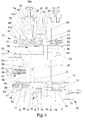
- reference number 1 globally indicates a device for controlling the braking of a trailer.
- the device 1 comprises a body 2 wherein is formed at least a first seat 3 communicating with at least a main gap 4 connectable to a source of a work fluid at a first pressure, with at least an exhaust gap 5 of the work fluid, and with at least a braking gap 6 communicating with at least a first line 7 connectable to the braking system of a trailer.
- unidirectional valve means are arranged, identified in the illustrations by the reference number 51, able to prevent the return of the work fluid towards the supply source of same.
- the first seat 3 is also communicating with at least a service gap 8 connectable to at least an external user point or in exhaust mode and/or with a load-sensing gap (not shown in the illustrations).
- a service gap 8 can be closed in the event of the work fluid being supplied by means of a variable flow rate pump.
- the first seat 3 can also be communicating with a load-sensing port.
- first distributor element 9 which is movable between at least an idle position, wherein the braking gap 6 is placed in communication with the exhaust gap 5, and at least a braking position, wherein the main gap 4 is placed in communication with the braking gap 6, so as to send the work fluid under pressure to the braking system of the trailer.
- the main gap 4 is placed in communication with the service gap 8 with the first distributor element 9 in the idle position.
- Piloting means 10 are also provided of the first distributor element 9 connectable to the braking system of a towing vehicle.
- the piloting means 10 comprise a piloting channel 11 connectable to the brake pump of the towing vehicle and acting on a piloting element 12 which in turn is able to interact with the first distributor element 9.
- piloting element 12 is arranged resting against a thrust element 13 which acts, by means of elastic means 14, on a connecting element 15 which in turn is able to interact with the first distributor element 9.
- the elastic means 14 are therefore able to apply a predefined force on the first distributor element 9 following the increase in pressure in the piloting channel 11 and, therefore, following the shift of the piloting element 12.
- the first distributor element 9 has a reaction surface communicating with the braking gap 6 and which acts in the opposite direction to the piloting means 10.
- inside the first seat 3 are defined two chambers, of which a first chamber 3a and a second chamber 3b, which act on the first distributor element 9 from opposite sides of same.
- the first chamber 3a acts on the first distributor element 9 on the opposite side with respect to the piloting means 10.
- the chambers 3a and 3b are both communicating with the braking gap 6. More in detail, the chambers 3a and 3b are mutually communicating through a channel 16 obtained inside the first distributor element 9 and have mutually different thrust areas, the difference in which defines the above-mentioned reaction surface.
- the first distributor element 9 then moves from the idle position to the braking position in contrast to elastic means 17 arranged on the opposite side of the elastic means 14 with respect to the first distributor element itself.
- the elastic means 17 are housed inside the first chamber 3a and are interposed between the first distributor element 9 and an abutment element 18 arranged at the bottom of the first seat 3.
- the device 1 also comprises mechanical control means 19, operable to control the shift of the first distributor element 9 from the idle position to the braking position.
- the control means 19 comprise at least a lever 20 arranged externally to the body 2, connectable to the parking brake of the towing vehicle and able to interact with the first distributor element 9. More particularly, the lever 20 acts on a cam element 21 which has a tooth able to interact with the piloting element 12 by means of intermediate elastic means 61 not preloaded or having a preload below the elastic means 14. The intermediate elastic means 61 allow obtaining a command proportionate to the stroke of the lever 20.
- the cam element 21 is arranged outside the body 2 and interacts with a cup-shaped element 62 inside which the intermediate elastic means 61 are housed which in turn interact with the piloting element 12 by means of a roller 63.
- the lever 20 is therefore movable between a first work position, wherein the first distributor element 9 is free to move, and a second work position, wherein the first distributor element 9 is brought to the braking position due to the action applied on it by the elastic means 14 following the shift of the thrust element 13.
- a second seat 22 communicating with a secondary gap 23 connectable to a source of the work fluid at a second pressure, preferably lower than the aforementioned first pressure, with the exhaust gap 5 and with at least an additional gap 25 communicating with a second line 26 connectable to the automatic and/or parking brake of the trailer.
- a second distributor element 27 movable between a normal operating position, wherein the additional gap 25 is placed in communication with the secondary gap 23, and an emergency position, wherein the additional gap 25 is placed in communication with the exhaust gap 5 so as to allow the operation of the automatic and/or parking brake of the trailer.
- the device 1 comprises command means 31 of the shift of the second distributor element 27 from the normal operating position towards the emergency position.
- the command means 31 comprise at least a command channel 32, 33 communicating with the thrust chamber 28, connectable to the secondary gap 23 and to the exhaust gap 5 and valve means 34, 35, 36, 9 operable to place the command channel 32, 33 in communication at least with the exhaust gap 5, so as to permit the shift of the second distributor element 27 to the emergency position.
- the pressure in the thrust chamber 28 substantially resets thus allowing the shift of the second distributor element 27 to the emergency position and, therefore, the operation of the automatic and/or parking brake of the trailer.
- command means 31 comprise a first command channel 32 communicating with the thrust chamber 28 and connectable to the secondary gap 23 and first valve means 34 which can be operated to place the first command channel 32 in communication with at least with the exhaust gap 5.
- the command means 31 also comprise, in addition to the first command channel 32 communicating with the thrust chamber 28, a supply channel 37 communicating with the secondary gap 23; the first valve means 34 are interposed between the first command channel 32 and the supply channel 37 and are operable to selectively place the first command channel 32 in communication with the supply channel 37 or with the exhaust gap 5.
- the first valve means 34 are of the type of a three-way valve, two of which are composed of the first command channel 32 and of the supply channel 37, whereas the third one is composed of the connecting channel 38 connecting to the exhaust gap 5.
- the first command channel 32 is directly connected to the secondary gap 23.
- the first valve means 34 are of the type of a two-way valve, one of which is composed of the first command channel 32 and the other of the connecting channel 38 connecting to the exhaust gap 5, operable to isolate/place in communication the first command channel 32 from/with the exhaust gap 5.
- the first valve means 34 are preferably of the type of a solenoid valve operatively connected to at least one of the engine and the parking brake of the towing vehicle and able to place the first command channel 32 in communication with the exhaust gap 5 when the engine of the towing vehicle is stationary or when the parking brake is operated, respectively.
- the device 1 also comprises pressure limiting means for limiting the pressure, identified by the reference number 40 in Figure 2 , interposed between the secondary gap 23 and the second seat 22. More particularly, the pressure limiting means 40 are able to isolate the secondary gap 23 from the second seat 22 in the event of the pressure of the work fluid crossing it exceeds a predefined value.
- the command means 31 also comprise second valve means 35 manually operable by an operator to place the first command channel 32 in communication with the exhaust gap 5.
- the second valve means 35 can be provided in addition or alternatively, as is the case of Figure 4 , to the first valve means 34.
- the second valve means 35 are manually movable between a first configuration, wherein they place the supply channel 37 in communication with the first command channel 32, and a second configuration, wherein they place the first command channel itself in communication with the connecting channel 38.
- the body 2 may also have an auxiliary port 50, not shown in the illustrations, communicating with the first command channel 32 and usable by an operator to connect it to an external user point in order to drain the work fluid coming from the secondary gap 23.
- command means 31 also comprise third valve means 36 operable to place the thrust chamber 28 in communication with the exhaust gap 5 following a pressure drop along the first line 7, e.g. caused by a breakage along the control line.
- the command means 31 comprise at least a third seat 41 formed in the body 2 and within which is housed sliding at least an actuator element 42 which splits the third seat 41 into a first chamber 41a communicating with a first length 7a of the first line 7 and into a second chamber 41b communicating with a second length 7b of the first line itself and arranged downstream of the first length 7a. Between the first and the second length 7a and 7b is conveniently interposed a calibrated orifice 43 which affects the intervention time of the actuator element 42.
- the actuator element 42 shifts in contrast to the elastic means 49 arranged inside the second chamber 41b.
- the command means 31 also comprise a second command channel 33 communicating with the thrust chamber 28, an exhaust channel 44 communicating with the exhaust gap 5; the third valve means 36 are able to place in communication/isolate the second command channel 33 with/from the exhaust channel 44.
- the second command channel 33 is in communication by means of the thrust chamber 28 with the first command channel 32, the pressure of the work fluid is therefore the same. It follows therefore that the pressure inside the thrust chamber 28 resets following the exhaust connection of each of the two command channels 32, 33.
- the actuator element 42 is able to shift, due to the reaching of a predefined pressure difference between the first and the second length 7a and 7b, from an inactive position, wherein it does not interact with the third valve means 36, to an active position, wherein it intervenes on the third valve means 36 to place the second command channel 33 in communication with the exhaust channel 44, so as to exhaust the work fluid contained in the thrust chamber 28 and allow the shift of the second distributor element 27 to the emergency position.
- the third valve means 36 comprise at least a shutter 36a protruding into the second chamber 41b and which is able to be intercepted by the actuator element 42 in its shift from the inactive position to the active position so as to place the second command channel 33 in communication with the exhaust channel 44.
- the second and third seat 22 and 41 are communicating together and a separation element 45 is interposed between them and is able to isolate fluid-dynamically the seat themselves, and the shutter 36a is inserted sealed in a sliding manner inside the separation element 45.
- a narrowing 52 is interposed which is able to slow down the intervention time of the actuator element 42.
- the intervention time of the actuator element 42 also depends on the stiffness of the elastic means 49, on the relevant thrust areas on which the chambers 41a and 41b act and on the length of its stroke.
- the first seat 3 also comprises an emergency gap 46 and the first distributor element 9 has an emergency position wherein the emergency gap itself is placed in communication with the exhaust gap 5.
- the lack of pressure in the chamber 3a able to counterbalance the force applied by the elastic means 14 entails an overrun of the first distributor element itself.
- the first distributor element 9 contacts the abutment element 18, on which act further elastic means 47 able to counteract the shift of the first distributor element itself towards the emergency position.
- the elastic means 47 are able to absorb at least part of the force applied by the elastic means 14, so as to slow down the shift of the first distributor element 9 towards the emergency position.
- the further elastic means 47 are arranged inside a further chamber 53 arranged on the opposite side of the first chamber 3a with respect to the abutment element 18.
- the abutment element 18 also defines a transit channel 54 able to place the first chamber 3a in communication with the further chamber 53 and along which at least one narrowing 55 is defined.
- the command means 31 also comprise at least an intermediate channel 48 communicating on one side with the emergency gap 46 and on the other side with the first command channel 32 and fourth valve means able to place the first command channel itself with the exhaust gap 5.
- the fourth valve means are defined by the first distributor element 9 which, by placing the emergency gap 46 in communication with the exhaust gap 5 in its emergency position, enables the drainage of the work fluid contained in the first command channel 32.
- the command means 31 may also comprise further valve means 56 arranged along the intermediate channel 48 and able to slow down the intervention time of the automatic and/or parking brake of the trailer.
- the further valve means 56 are able to shift themselves from a first position, wherein they interrupt the connection between the emergency gap 46 and the first command channel 32, and a second position, wherein they place the emergency gap 46 in communication with the first command channel itself to allow the drainage of the work fluid from the thrust chamber 28 towards the exhaust gap 5 following the reaching of the emergency position by the first distributor element 9.
- the further valve means 56 comprise a further distributor element 57 housed sliding inside a further seat 58 defined in the body 2 and communicating on one side with the secondary gap 23 and on the other side with the emergency gap 46.
- the further distributor element 57 divides the further seat 58 into two chambers opposite one another and communicating through a narrowing 59 and also has an inner channel 60 able to place the emergency gap 46 in communication with the first command channel 32 upon reaching the second work position.
- the first distributor element 9 In normal operating conditions, as long as the brakes of the towing vehicle are not operated, the first distributor element 9 is in idle position, so that the main gap 4 is placed in communication with the service gap 8 and the braking gap 6 is placed in communication with the exhaust gap 5.
- the piloting element 12 acts on the thrust element 13 which, by shifting, compresses the elastic means 14 which, consequently, by means of the connecting element 15, push the first distributor element 9 towards the braking position.
- the narrowing occurs of the connection between the main gap 4 and the service gap 8, thereby causing an increase in pressure in the main gap itself.
- the main gap 4 is placed in communication with the braking gap 6.
- the first distributor element 9 then reaches a position of equilibrium wherein the force applied by the elastic means 14 is balanced by the force due to the pressure in the chambers 3a and 3b and to the elastic means 17.
- the unidirectional valve means 51 arranged at the main gap 4 prevent the outflow of the work fluid under pressure from the braking system of the trailer towards the supply source.
- the lever 20 moves from the first work position to the second work position consequently causing the shift of the thrust element 13 and, therefore, the braking of the trailer.
- the second distributor element 27 takes up a normal operating position, wherein the additional gap 25 is placed in communication with the secondary gap 23, in such a way as to maintain the automatic and/or parking brake of the trailer disabled.
- the thrust chamber 28 is connected, by means of the first command channel 32 to the secondary gap 23, so that the pressure inside it is such as to overcome the force applied by the elastic means 30.
- the first command channel 32 is placed in communication with the supply channel 37 through the solenoid valve 34 when the engine of the towing vehicle is operating whereas, following its being turned off, e.g. after a predefined time interval in case the pressure along the additional line does not quickly reset, or following the operation of the relative parking brake, the solenoid valve itself places the first command channel 32 in communication with the connecting channel 38, thereby enabling the work fluid contained in the thrust chamber 28 to be drained off and enabling the second distributor element 27 to shift to the emergency position. As described above, such shift involves the operation of the automatic and/or parking brake of the trailer.
- the first command channel 32 is constantly in communication with the secondary gap 23 and the solenoid valve 34 which, in normal operating condition (i.e., with the engine of the towing vehicle running) keeps the first command channel 32 isolated from the exhaust gap 5, and is able to place the first command channel 32 in communication with the exhaust gap itself following the switching off of the engine of the towing vehicle or following the operation of its parking brake, in such a way as to drain the work fluid coming from the secondary gap 23 and allow the operation of the automatic and/or parking brake of the trailer.
- the solenoid valve 34 which, in normal operating condition (i.e., with the engine of the towing vehicle running) keeps the first command channel 32 isolated from the exhaust gap 5, and is able to place the first command channel 32 in communication with the exhaust gap itself following the switching off of the engine of the towing vehicle or following the operation of its parking brake, in such a way as to drain the work fluid coming from the secondary gap 23 and allow the operation of the automatic and/or parking brake of the trailer.
- the exhaust connection of the work fluid contained in the thrust chamber 28 can also be obtained in the following ways: by means of the manual operation of the second valve means 35, by means of the connection of an external user point to the auxiliary port 50, by means of the third valve means 36 following a drop in pressure generated by the loss of the work fluid along the first line 7, or by the reaching of the braking position by the first distributor element 9 following the lack of supply of the work fluid from the main gap 4.
- the actuator element 42 shifts until it contacts the shutter 36a, in such a way as to place the second command channel 33 in communication with the exhaust channel 44 and, therefore, with the exhaust gap 5.
- the first distributor element 9 performs an overrun towards the abutment element 18 and moves to the emergency position thus placing the emergency gap 46, and consequently also the first command channel 32 through the intermediate channel 48, in communication with the exhaust gap 5.
- a solenoid valve operatively connected to the control system of the engine of the towing vehicle also permits operating the automatic and/or parking brake of the trailer also in the event of the switching off of the engine of the towing vehicle not resulting in the automatic pressure reset along the additional line.
- the device to which the present invention refers allows the emergency braking of the trailer in three distinct conditions, i.e., in case of no supply of work fluid through the main gap, in case of leaks along the braking system of the trailer or in the case of mechanical command by means of the handbrake lever.
Landscapes
- Engineering & Computer Science (AREA)
- Transportation (AREA)
- Mechanical Engineering (AREA)
- Valves And Accessory Devices For Braking Systems (AREA)
- Regulating Braking Force (AREA)
Applications Claiming Priority (1)
| Application Number | Priority Date | Filing Date | Title |
|---|---|---|---|
| ITMO2015A000046A ITMO20150046A1 (it) | 2015-03-04 | 2015-03-04 | Dispositivo per il controllo della frenatura di un rimorchio |
Publications (2)
| Publication Number | Publication Date |
|---|---|
| EP3064408A1 true EP3064408A1 (fr) | 2016-09-07 |
| EP3064408B1 EP3064408B1 (fr) | 2018-01-31 |
Family
ID=53052994
Family Applications (1)
| Application Number | Title | Priority Date | Filing Date |
|---|---|---|---|
| EP16158783.7A Active EP3064408B1 (fr) | 2015-03-04 | 2016-03-04 | Dispositif de reglage de freinage de remorque |
Country Status (2)
| Country | Link |
|---|---|
| EP (1) | EP3064408B1 (fr) |
| IT (1) | ITMO20150046A1 (fr) |
Cited By (1)
| Publication number | Priority date | Publication date | Assignee | Title |
|---|---|---|---|---|
| EP3319848B1 (fr) * | 2015-07-08 | 2019-10-09 | SAFIM S.p.A. | Dispositif d'actionnement d'une vanne pour le freinage d'une remorque |
Citations (4)
| Publication number | Priority date | Publication date | Assignee | Title |
|---|---|---|---|---|
| US3718373A (en) * | 1970-11-13 | 1973-02-27 | Bosch Gmbh Robert | Arrangement for controlling the brake systems of trailers or the like |
| EP0015689A1 (fr) * | 1979-02-23 | 1980-09-17 | Wabco Automotive U.K. Limited | Systèmes de freinage hydraulique pour des combinaisons tracteur/remorque |
| FR2496577A1 (fr) * | 1980-12-18 | 1982-06-25 | Fiat Trattori Spa | Installation de freinage hydraulique pour remorques de vehicules automobiles, en particulier, pour remorques agricoles |
| WO2014001876A1 (fr) | 2012-06-28 | 2014-01-03 | Studio Tecnico 6M S.R.L. | Dispositif de freinage d'une remorque |
-
2015
- 2015-03-04 IT ITMO2015A000046A patent/ITMO20150046A1/it unknown
-
2016
- 2016-03-04 EP EP16158783.7A patent/EP3064408B1/fr active Active
Patent Citations (4)
| Publication number | Priority date | Publication date | Assignee | Title |
|---|---|---|---|---|
| US3718373A (en) * | 1970-11-13 | 1973-02-27 | Bosch Gmbh Robert | Arrangement for controlling the brake systems of trailers or the like |
| EP0015689A1 (fr) * | 1979-02-23 | 1980-09-17 | Wabco Automotive U.K. Limited | Systèmes de freinage hydraulique pour des combinaisons tracteur/remorque |
| FR2496577A1 (fr) * | 1980-12-18 | 1982-06-25 | Fiat Trattori Spa | Installation de freinage hydraulique pour remorques de vehicules automobiles, en particulier, pour remorques agricoles |
| WO2014001876A1 (fr) | 2012-06-28 | 2014-01-03 | Studio Tecnico 6M S.R.L. | Dispositif de freinage d'une remorque |
Cited By (1)
| Publication number | Priority date | Publication date | Assignee | Title |
|---|---|---|---|---|
| EP3319848B1 (fr) * | 2015-07-08 | 2019-10-09 | SAFIM S.p.A. | Dispositif d'actionnement d'une vanne pour le freinage d'une remorque |
Also Published As
| Publication number | Publication date |
|---|---|
| EP3064408B1 (fr) | 2018-01-31 |
| ITMO20150046A1 (it) | 2016-09-04 |
Similar Documents
| Publication | Publication Date | Title |
|---|---|---|
| CN107771140B (zh) | 机动车用驻车制动机构 | |
| US20090111636A1 (en) | Electroyhydraulic control device of a gear unit | |
| KR101649009B1 (ko) | 압축 공기 제동 시스템용 트레일러 제어 밸브 | |
| US20140159473A1 (en) | Brake system pedal simulator connection | |
| US10215280B2 (en) | Hydraulic system of an automatic transmission with multiple valve devices | |
| US9670978B2 (en) | Parking brake | |
| RU2694674C1 (ru) | Клапан ограничения давления | |
| EP3064408B1 (fr) | Dispositif de reglage de freinage de remorque | |
| EP3085590B1 (fr) | Unite' de controle pour un système de freinage d'un remorque | |
| EP2371642B1 (fr) | Appareil de régulation de flux et circuit de commande de frein avec appareil de régulation de flux | |
| US9550504B2 (en) | Rail vehicle braking system and braking method for a rail vehicle comprising such a system | |
| EP3401176B1 (fr) | Engin pout contrôller les freins d'un remorque | |
| US20100243402A1 (en) | Device for actuating a dual clutch transmission | |
| EP2952398B1 (fr) | Dispositif de soupape | |
| EP3368385B1 (fr) | Dispositif de freinage pour remorques de machines agricoles | |
| EP3000672B1 (fr) | Système de soupape pour remorque | |
| JPS5932351B2 (ja) | ブレ−キ弁 | |
| EP3319848B1 (fr) | Dispositif d'actionnement d'une vanne pour le freinage d'une remorque | |
| EP3225473B1 (fr) | Dispositif pour la commande de freinage de remorque | |
| CN210623538U (zh) | 自动变速器的液压控制装置 | |
| EP3401177B1 (fr) | Dispositif de controle pour soupape de frein de remorque, adapte a etre integré dans le système de freinage du remorque. | |
| CN110594405A (zh) | 自动变速器的液压控制装置 | |
| EP3085589B1 (fr) | Dispositif de vanne | |
| EP2876009B1 (fr) | Dispositif de commande de soupape de freinage de remorque | |
| EP3401175B1 (fr) | Engin pour le réglage des freins d'un remorque |
Legal Events
| Date | Code | Title | Description |
|---|---|---|---|
| PUAI | Public reference made under article 153(3) epc to a published international application that has entered the european phase |
Free format text: ORIGINAL CODE: 0009012 |
|
| AK | Designated contracting states |
Kind code of ref document: A1 Designated state(s): AL AT BE BG CH CY CZ DE DK EE ES FI FR GB GR HR HU IE IS IT LI LT LU LV MC MK MT NL NO PL PT RO RS SE SI SK SM TR |
|
| AX | Request for extension of the european patent |
Extension state: BA ME |
|
| STAA | Information on the status of an ep patent application or granted ep patent |
Free format text: STATUS: REQUEST FOR EXAMINATION WAS MADE |
|
| 17P | Request for examination filed |
Effective date: 20170302 |
|
| RBV | Designated contracting states (corrected) |
Designated state(s): AL AT BE BG CH CY CZ DE DK EE ES FI FR GB GR HR HU IE IS IT LI LT LU LV MC MK MT NL NO PL PT RO RS SE SI SK SM TR |
|
| RIC1 | Information provided on ipc code assigned before grant |
Ipc: B60T 15/18 20060101ALI20170704BHEP Ipc: B60T 13/16 20060101AFI20170704BHEP Ipc: B60T 15/02 20060101ALI20170704BHEP |
|
| GRAP | Despatch of communication of intention to grant a patent |
Free format text: ORIGINAL CODE: EPIDOSNIGR1 |
|
| STAA | Information on the status of an ep patent application or granted ep patent |
Free format text: STATUS: GRANT OF PATENT IS INTENDED |
|
| INTG | Intention to grant announced |
Effective date: 20170825 |
|
| GRAS | Grant fee paid |
Free format text: ORIGINAL CODE: EPIDOSNIGR3 |
|
| GRAA | (expected) grant |
Free format text: ORIGINAL CODE: 0009210 |
|
| STAA | Information on the status of an ep patent application or granted ep patent |
Free format text: STATUS: THE PATENT HAS BEEN GRANTED |
|
| AK | Designated contracting states |
Kind code of ref document: B1 Designated state(s): AL AT BE BG CH CY CZ DE DK EE ES FI FR GB GR HR HU IE IS IT LI LT LU LV MC MK MT NL NO PL PT RO RS SE SI SK SM TR |
|
| REG | Reference to a national code |
Ref country code: GB Ref legal event code: FG4D Ref country code: CH Ref legal event code: EP |
|
| REG | Reference to a national code |
Ref country code: AT Ref legal event code: REF Ref document number: 967057 Country of ref document: AT Kind code of ref document: T Effective date: 20180215 |
|
| REG | Reference to a national code |
Ref country code: IE Ref legal event code: FG4D |
|
| REG | Reference to a national code |
Ref country code: DE Ref legal event code: R096 Ref document number: 602016001475 Country of ref document: DE |
|
| REG | Reference to a national code |
Ref country code: FR Ref legal event code: PLFP Year of fee payment: 3 |
|
| RAP2 | Party data changed (patent owner data changed or rights of a patent transferred) |
Owner name: SAFIM S.P.A. |
|
| REG | Reference to a national code |
Ref country code: GB Ref legal event code: 732E Free format text: REGISTERED BETWEEN 20180329 AND 20180404 |
|
| REG | Reference to a national code |
Ref country code: NL Ref legal event code: MP Effective date: 20180131 |
|
| REG | Reference to a national code |
Ref country code: LT Ref legal event code: MG4D |
|
| REG | Reference to a national code |
Ref country code: AT Ref legal event code: MK05 Ref document number: 967057 Country of ref document: AT Kind code of ref document: T Effective date: 20180131 |
|
| PG25 | Lapsed in a contracting state [announced via postgrant information from national office to epo] |
Ref country code: FI Free format text: LAPSE BECAUSE OF FAILURE TO SUBMIT A TRANSLATION OF THE DESCRIPTION OR TO PAY THE FEE WITHIN THE PRESCRIBED TIME-LIMIT Effective date: 20180131 Ref country code: ES Free format text: LAPSE BECAUSE OF FAILURE TO SUBMIT A TRANSLATION OF THE DESCRIPTION OR TO PAY THE FEE WITHIN THE PRESCRIBED TIME-LIMIT Effective date: 20180131 Ref country code: NL Free format text: LAPSE BECAUSE OF FAILURE TO SUBMIT A TRANSLATION OF THE DESCRIPTION OR TO PAY THE FEE WITHIN THE PRESCRIBED TIME-LIMIT Effective date: 20180131 Ref country code: HR Free format text: LAPSE BECAUSE OF FAILURE TO SUBMIT A TRANSLATION OF THE DESCRIPTION OR TO PAY THE FEE WITHIN THE PRESCRIBED TIME-LIMIT Effective date: 20180131 Ref country code: NO Free format text: LAPSE BECAUSE OF FAILURE TO SUBMIT A TRANSLATION OF THE DESCRIPTION OR TO PAY THE FEE WITHIN THE PRESCRIBED TIME-LIMIT Effective date: 20180430 Ref country code: LT Free format text: LAPSE BECAUSE OF FAILURE TO SUBMIT A TRANSLATION OF THE DESCRIPTION OR TO PAY THE FEE WITHIN THE PRESCRIBED TIME-LIMIT Effective date: 20180131 |
|
| PG25 | Lapsed in a contracting state [announced via postgrant information from national office to epo] |
Ref country code: GR Free format text: LAPSE BECAUSE OF FAILURE TO SUBMIT A TRANSLATION OF THE DESCRIPTION OR TO PAY THE FEE WITHIN THE PRESCRIBED TIME-LIMIT Effective date: 20180501 Ref country code: AT Free format text: LAPSE BECAUSE OF FAILURE TO SUBMIT A TRANSLATION OF THE DESCRIPTION OR TO PAY THE FEE WITHIN THE PRESCRIBED TIME-LIMIT Effective date: 20180131 Ref country code: RS Free format text: LAPSE BECAUSE OF FAILURE TO SUBMIT A TRANSLATION OF THE DESCRIPTION OR TO PAY THE FEE WITHIN THE PRESCRIBED TIME-LIMIT Effective date: 20180131 Ref country code: BG Free format text: LAPSE BECAUSE OF FAILURE TO SUBMIT A TRANSLATION OF THE DESCRIPTION OR TO PAY THE FEE WITHIN THE PRESCRIBED TIME-LIMIT Effective date: 20180430 Ref country code: IS Free format text: LAPSE BECAUSE OF FAILURE TO SUBMIT A TRANSLATION OF THE DESCRIPTION OR TO PAY THE FEE WITHIN THE PRESCRIBED TIME-LIMIT Effective date: 20180531 Ref country code: SE Free format text: LAPSE BECAUSE OF FAILURE TO SUBMIT A TRANSLATION OF THE DESCRIPTION OR TO PAY THE FEE WITHIN THE PRESCRIBED TIME-LIMIT Effective date: 20180131 Ref country code: LV Free format text: LAPSE BECAUSE OF FAILURE TO SUBMIT A TRANSLATION OF THE DESCRIPTION OR TO PAY THE FEE WITHIN THE PRESCRIBED TIME-LIMIT Effective date: 20180131 Ref country code: PL Free format text: LAPSE BECAUSE OF FAILURE TO SUBMIT A TRANSLATION OF THE DESCRIPTION OR TO PAY THE FEE WITHIN THE PRESCRIBED TIME-LIMIT Effective date: 20180131 |
|
| REG | Reference to a national code |
Ref country code: DE Ref legal event code: R081 Ref document number: 602016001475 Country of ref document: DE Owner name: SAFIM S.P.A., IT Free format text: FORMER OWNER: STUDIO TECNICO 6 M S.R.L., MODENA, IT |
|
| PG25 | Lapsed in a contracting state [announced via postgrant information from national office to epo] |
Ref country code: EE Free format text: LAPSE BECAUSE OF FAILURE TO SUBMIT A TRANSLATION OF THE DESCRIPTION OR TO PAY THE FEE WITHIN THE PRESCRIBED TIME-LIMIT Effective date: 20180131 Ref country code: RO Free format text: LAPSE BECAUSE OF FAILURE TO SUBMIT A TRANSLATION OF THE DESCRIPTION OR TO PAY THE FEE WITHIN THE PRESCRIBED TIME-LIMIT Effective date: 20180131 Ref country code: AL Free format text: LAPSE BECAUSE OF FAILURE TO SUBMIT A TRANSLATION OF THE DESCRIPTION OR TO PAY THE FEE WITHIN THE PRESCRIBED TIME-LIMIT Effective date: 20180131 |
|
| REG | Reference to a national code |
Ref country code: DE Ref legal event code: R097 Ref document number: 602016001475 Country of ref document: DE |
|
| PG25 | Lapsed in a contracting state [announced via postgrant information from national office to epo] |
Ref country code: SK Free format text: LAPSE BECAUSE OF FAILURE TO SUBMIT A TRANSLATION OF THE DESCRIPTION OR TO PAY THE FEE WITHIN THE PRESCRIBED TIME-LIMIT Effective date: 20180131 Ref country code: MC Free format text: LAPSE BECAUSE OF FAILURE TO SUBMIT A TRANSLATION OF THE DESCRIPTION OR TO PAY THE FEE WITHIN THE PRESCRIBED TIME-LIMIT Effective date: 20180131 Ref country code: DK Free format text: LAPSE BECAUSE OF FAILURE TO SUBMIT A TRANSLATION OF THE DESCRIPTION OR TO PAY THE FEE WITHIN THE PRESCRIBED TIME-LIMIT Effective date: 20180131 Ref country code: SM Free format text: LAPSE BECAUSE OF FAILURE TO SUBMIT A TRANSLATION OF THE DESCRIPTION OR TO PAY THE FEE WITHIN THE PRESCRIBED TIME-LIMIT Effective date: 20180131 Ref country code: CZ Free format text: LAPSE BECAUSE OF FAILURE TO SUBMIT A TRANSLATION OF THE DESCRIPTION OR TO PAY THE FEE WITHIN THE PRESCRIBED TIME-LIMIT Effective date: 20180131 |
|
| PLBE | No opposition filed within time limit |
Free format text: ORIGINAL CODE: 0009261 |
|
| STAA | Information on the status of an ep patent application or granted ep patent |
Free format text: STATUS: NO OPPOSITION FILED WITHIN TIME LIMIT |
|
| REG | Reference to a national code |
Ref country code: BE Ref legal event code: MM Effective date: 20180331 |
|
| REG | Reference to a national code |
Ref country code: IE Ref legal event code: MM4A |
|
| PG25 | Lapsed in a contracting state [announced via postgrant information from national office to epo] |
Ref country code: LU Free format text: LAPSE BECAUSE OF NON-PAYMENT OF DUE FEES Effective date: 20180304 |
|
| 26N | No opposition filed |
Effective date: 20181102 |
|
| PG25 | Lapsed in a contracting state [announced via postgrant information from national office to epo] |
Ref country code: IE Free format text: LAPSE BECAUSE OF NON-PAYMENT OF DUE FEES Effective date: 20180304 |
|
| PG25 | Lapsed in a contracting state [announced via postgrant information from national office to epo] |
Ref country code: BE Free format text: LAPSE BECAUSE OF NON-PAYMENT OF DUE FEES Effective date: 20180331 Ref country code: SI Free format text: LAPSE BECAUSE OF FAILURE TO SUBMIT A TRANSLATION OF THE DESCRIPTION OR TO PAY THE FEE WITHIN THE PRESCRIBED TIME-LIMIT Effective date: 20180131 |
|
| REG | Reference to a national code |
Ref country code: CH Ref legal event code: PL |
|
| PG25 | Lapsed in a contracting state [announced via postgrant information from national office to epo] |
Ref country code: CH Free format text: LAPSE BECAUSE OF NON-PAYMENT OF DUE FEES Effective date: 20190331 Ref country code: LI Free format text: LAPSE BECAUSE OF NON-PAYMENT OF DUE FEES Effective date: 20190331 Ref country code: MT Free format text: LAPSE BECAUSE OF NON-PAYMENT OF DUE FEES Effective date: 20180304 |
|
| PG25 | Lapsed in a contracting state [announced via postgrant information from national office to epo] |
Ref country code: TR Free format text: LAPSE BECAUSE OF FAILURE TO SUBMIT A TRANSLATION OF THE DESCRIPTION OR TO PAY THE FEE WITHIN THE PRESCRIBED TIME-LIMIT Effective date: 20180131 |
|
| PG25 | Lapsed in a contracting state [announced via postgrant information from national office to epo] |
Ref country code: PT Free format text: LAPSE BECAUSE OF FAILURE TO SUBMIT A TRANSLATION OF THE DESCRIPTION OR TO PAY THE FEE WITHIN THE PRESCRIBED TIME-LIMIT Effective date: 20180131 |
|
| PG25 | Lapsed in a contracting state [announced via postgrant information from national office to epo] |
Ref country code: CY Free format text: LAPSE BECAUSE OF FAILURE TO SUBMIT A TRANSLATION OF THE DESCRIPTION OR TO PAY THE FEE WITHIN THE PRESCRIBED TIME-LIMIT Effective date: 20180131 Ref country code: HU Free format text: LAPSE BECAUSE OF FAILURE TO SUBMIT A TRANSLATION OF THE DESCRIPTION OR TO PAY THE FEE WITHIN THE PRESCRIBED TIME-LIMIT; INVALID AB INITIO Effective date: 20160304 Ref country code: MK Free format text: LAPSE BECAUSE OF NON-PAYMENT OF DUE FEES Effective date: 20180131 |
|
| P01 | Opt-out of the competence of the unified patent court (upc) registered |
Effective date: 20230527 |
|
| PGFP | Annual fee paid to national office [announced via postgrant information from national office to epo] |
Ref country code: DE Payment date: 20240327 Year of fee payment: 9 Ref country code: GB Payment date: 20240327 Year of fee payment: 9 |
|
| PGFP | Annual fee paid to national office [announced via postgrant information from national office to epo] |
Ref country code: IT Payment date: 20240321 Year of fee payment: 9 Ref country code: FR Payment date: 20240325 Year of fee payment: 9 |