EP3064363A1 - Printer - Google Patents
Printer Download PDFInfo
- Publication number
- EP3064363A1 EP3064363A1 EP14888170.9A EP14888170A EP3064363A1 EP 3064363 A1 EP3064363 A1 EP 3064363A1 EP 14888170 A EP14888170 A EP 14888170A EP 3064363 A1 EP3064363 A1 EP 3064363A1
- Authority
- EP
- European Patent Office
- Prior art keywords
- paper
- shaft
- printer
- housing
- disposed
- Prior art date
- Legal status (The legal status is an assumption and is not a legal conclusion. Google has not performed a legal analysis and makes no representation as to the accuracy of the status listed.)
- Granted
Links
Images




Classifications
-
- B—PERFORMING OPERATIONS; TRANSPORTING
- B41—PRINTING; LINING MACHINES; TYPEWRITERS; STAMPS
- B41J—TYPEWRITERS; SELECTIVE PRINTING MECHANISMS, i.e. MECHANISMS PRINTING OTHERWISE THAN FROM A FORME; CORRECTION OF TYPOGRAPHICAL ERRORS
- B41J29/00—Details of, or accessories for, typewriters or selective printing mechanisms not otherwise provided for
- B41J29/02—Framework
-
- B—PERFORMING OPERATIONS; TRANSPORTING
- B41—PRINTING; LINING MACHINES; TYPEWRITERS; STAMPS
- B41J—TYPEWRITERS; SELECTIVE PRINTING MECHANISMS, i.e. MECHANISMS PRINTING OTHERWISE THAN FROM A FORME; CORRECTION OF TYPOGRAPHICAL ERRORS
- B41J15/00—Devices or arrangements of selective printing mechanisms, e.g. ink-jet printers or thermal printers, specially adapted for supporting or handling copy material in continuous form, e.g. webs
- B41J15/04—Supporting, feeding, or guiding devices; Mountings for web rolls or spindles
- B41J15/042—Supporting, feeding, or guiding devices; Mountings for web rolls or spindles for loading rolled-up continuous copy material into printers, e.g. for replacing a used-up paper roll; Point-of-sale printers with openable casings allowing access to the rolled-up continuous copy material
-
- B—PERFORMING OPERATIONS; TRANSPORTING
- B41—PRINTING; LINING MACHINES; TYPEWRITERS; STAMPS
- B41J—TYPEWRITERS; SELECTIVE PRINTING MECHANISMS, i.e. MECHANISMS PRINTING OTHERWISE THAN FROM A FORME; CORRECTION OF TYPOGRAPHICAL ERRORS
- B41J15/00—Devices or arrangements of selective printing mechanisms, e.g. ink-jet printers or thermal printers, specially adapted for supporting or handling copy material in continuous form, e.g. webs
- B41J15/04—Supporting, feeding, or guiding devices; Mountings for web rolls or spindles
Definitions
- the present invention relates to a printer using large-sized heavy roll paper as a recording object.
- a conventional printer performs a recording operation on a long paper sheet wound into a roll shape (roll paper).
- roll paper When such a printer uses a recording object that is roll paper large in size and heavy consequent to having a large diameter and width in the rolled state, a frame that holds the roll paper is formed of a metal plate-shaped member having a certain thickness so as to ensure the strength of the mechanism holding the roll paper.
- Printers include electrical system components for drive control and power supply to units included in the printer and these electrical system components must be insulated.
- the frame In the case of a configuration using a metal frame for holding roll paper, the frame must be insulated. Conventionally, for example, arrangement is such that insulation properties of the frame are ensured by coating the metal frame with a paint having high electrical insulation properties.
- Techniques related to a printer using roll paper as a recording object include, for example, a technique of a label printer that is configured to rotatably support a core shaft for mounting a label sheet and has a body core unit that is a cylindrical shape having a first diameter and insertable into a winding core portion of a label sheet and a label sheet mounting unit disposed at a predetermined part in a longitudinal middle portion of the body core unit and having a second diameter that is smaller than the first diameter (see, e.g., Patent Documents 1 and 2).
- the conventional techniques described above have the problem of a complicated configuration for insulating electrical system components disposed at multiple positions in the printer.
- the conventional techniques also have a problem in that the complicated configuration of the printer leads to increased manufacturing man-hours, a large worker burden required for manufacturing, and high manufacturing costs.
- the conventional techniques since the electrical system components are attached in an insulated state and a metal frame coated with a paint having high electrical insulation properties is separately disposed, the conventional techniques have the problems of increased manufacturing man-hours, a large worker burden required for manufacturing, and high manufacturing costs.
- the frame is coated with a paint having high insulation properties, which leads to problems of increased manufacturing man-hours, a large worker burden required for manufacturing, and high manufacturing costs.
- one object of the present invention is to reduce the manufacturing cost of a printer having ensured strength for holding large-diameter roll paper.
- a printer includes a housing forming a substantially box shape; a pair of frames disposed in the housing and arranged such that the frames oppose each other across a conveyance path of a recording medium; a cutout portion disposed at an upper end of each of the frames; a shaft that while inserted inside a winding core on which long paper is wound into a roll shape, both ends of the shaft are supported by the cutout portions and the shaft holds the paper while allowing the paper to be pulled out from the housing; and an exterior cover that is disposed in the housing, is formed using an insulating material, has openings that open the cutout portions exteriorly, and covers the pair of the frames with the cutout portions opened exteriorly through the openings.
- the printer according to the invention further includes electrical system components disposed in the housing and related to driving of units included in the printer, where the exterior cover also covers the electrical system components.
- the printer according to the present invention achieves an effect of enabling a reduction in manufacturing costs of a printer having ensured strength for holding large-diameter roll paper.
- FIG. 1 is an explanatory view of an exterior of the printer of the embodiment according to the present invention.
- Fig. 1 depicts the printer of the embodiment according to the present invention in an installed state, viewed obliquely from above.
- a printer 100 of the embodiment according to the present invention includes a housing 101 forming a hollow parallelepiped shape.
- the housing 101 includes a lower housing 101a having an opening in an upper aspect and forming a substantially box shape, and an upper housing 101b closing the opening of the lower housing 101a in an openable manner.
- the upper housing 101b has an opening in a lower aspect and closes the opening of the lower housing 101a with the opening of the upper housing opposing the opening of the lower housing 101a.
- the upper housing 101b is supported about an axis by the lower housing 101a, at a rear aspect of the printer 100 (on the right side of Fig. 1 ) and is thereby rotatably coupled to the lower housing 101a.
- the housing 101 With the opening of the lower housing 101a closed by the upper housing 101b, the housing 101 forms a housing space that houses a printer main body (see Figs. 4 and 5 ) inside the upper housing 101b and the lower housing 101a. With the opening of the lower housing 101a closed by the upper housing 101b, the housing 101 forms a discharge port 102 that discharges a recorded recording medium in a front surface (on the left side of Fig. 1 ) of the housing 101. The discharge port 102 is formed in a boundary portion between the upper housing 101b and the lower housing 101a.
- the front surface of the housing 101 (the lower housing 101a) is equipped with an operation panel 103.
- the operation panel 103 includes buttons 103a that receive various input operations and a display panel 103b that displays a state, etc. of the printer 100.
- the display panel 103b displays a given message to report the state of the printer 100 such as when the printer is powered on and put into a print stand-by state, an error occurs in the printer 100, or the remaining amount of paper held by the printer 100 becomes less than or equal to a predetermined amount.
- the display panel 103b can be realized by a liquid crystal display, for example.
- Figs. 2 and 3 are explanatory views of the printer 100 with the housing 101 opened.
- Fig. 2 depicts the printer 100 with the inside of the housing 101 opened exteriorly, as viewed from a position located on the upper right side with respect to the front surface of the printer 100.
- Fig. 3 depicts the printer 100 as viewed from a position located on the upper left side with respect to the front surface of the printer 100.
- the printer 100 includes a paper holding unit 202 that, at a rear aspect in the housing 110, holds a recording medium (paper) 201 that is used as a recording object and wound into a roll shape.
- the recording medium (paper) 201 used as a recording object may be continuous forms wound into a roll shape or may be a label sheet with multiple labels arranged along a longitudinal direction of a mount.
- the printer 100 includes a head unit 203 disposed closer to the front surface as compared to the paper holding unit 202 in the housing 101.
- a conveyance path is formed inside the housing 101 from the paper holding unit 202 via the head unit 203 to the discharge port 102.
- the paper 201 wound into a roll shape held by the paper holding unit 202 is pulled out from a longitudinal end portion on the outer circumference and conveyed via the head unit 203 to the discharge port 102.
- the head unit 203 includes a print head 204.
- the print head 204 performs a thermal type recording operation, for example.
- the print head 204 that performs a thermal type recording operation includes multiple heating elements arranged in a line along a width direction of the printer 100 (along a direction orthogonal to the conveyance direction of the paper 201).
- the printer 100 selectively energizes the heating elements in the thermal head to selectively cause the heating elements to generate heat and thereby performs the recording operation.
- the head unit 203 may include the print head 204 of another type of recording instead of the thermal type recording.
- a platen 205 is disposed facing the print head 204 across the conveyance path (the paper 201 being conveyed through the conveyance path).
- the platen 205 forms a substantially columnar shape having an axial direction that is along the width direction of the printer 100.
- the platen 205 supports a rear surface of the paper 201 while a pushing force is applied to a front surface (a recording surface) by the print head 204.
- the print head 204 is biased in a direction toward the platen 205.
- a motor (see reference numeral 507 of Fig. 5 ) is attached via a gear train not depicted.
- the gear train rotates by transmitting a drive force of the motor.
- the platen 205 rotates accompanying the rotation of gears making up the gear train.
- the platen 205 rotates and thereby, conveys the paper 201 in the conveyance path, from the paper holding unit 202 side toward the discharge port 102.
- the head unit 203 includes a ribbon unit 206 supporting an ink ribbon not depicted.
- the ribbon unit 206 includes a ribbon support shaft 207 supporting the ink ribbon before the ink ribbon is provided for a recording operation and a ribbon winding shaft 208 winding the ink ribbon after a recording operation.
- the ribbon unit 206 also includes a ribbon shaft drive mechanism that rotates the ribbon winding shaft 208 to feed the ink ribbon supported by the ribbon support shaft 207 and wind the fed ink ribbon around the ribbon winding shaft 208.
- the ribbon shaft drive mechanism is housed in a case 209 and is made up of a motor (see reference numeral 405 of Fig. 5 ), a wheel train that transmits the drive force of the motor to the ribbon winding shaft 208, a ribbon board that drives the motor, etc.
- Figs. 4 and 5 are side views of the head unit 203 and the printer main body.
- Fig. 4 depicts the printer main body with the housing 101 removed as viewed in the direction indicated by arrow A in Fig. 1 .
- Fig. 5 depicts the printer main body with the housing 101 removed viewed in the direction indicated by arrow B in Fig. 1 .
- Figs. 4 and 5 depict a state in which the case 209 is removed in the ribbon unit 206.
- the printer main body 400 includes a bottom frame 401 disposed in the housing 101.
- the bottom frame 401 is formed by sheet-metal working of a metal plate-shaped member having a predetermined thickness.
- a pair of shaft paper guides 402, 501 realizing a pair of frames is disposed in the bottom frame 401.
- the pair of the shaft paper guides 402, 501 is disposed at the position of the paper holding unit 202 in the housing 101.
- the pair of the shaft paper guides 402, 501 is disposed such that the shaft paper guides 402, 501 oppose each other along the width direction of the printer 100.
- the pair of the shaft paper guides 402, 501 is disposed such that the shaft paper guides 402, 501 oppose each other across the paper 201, which is wound into a roll shape.
- Cutout portions 402a, 501a are disposed respectively in upper ends of the pair of the shaft paper guides 402, 501.
- the cutout portions 402a, 501a form a rectangular shape opened on the upper side (a portion on the upper side in Figs. 4 and 5 ).
- the cutout portions 402a, 501a support a shaft 403 that holds the paper 201 that is wound into a roll shape and housed in the paper holding unit 202, the paper 201 being held such that the paper 201 can be pulled out from the paper holding unit 202.
- the shaft 403 can be realized by a rod-like member having a cross section forming a polygonal shape (e.g., a quadrangular shape).
- the shaft 403 is formed by using an insulating material such as a plastic material, for example.
- the cutout portions 402a, 501a are formed by partially cutting out the upper end portions of the pair of the shaft paper guides 402, 501 in a size and shape substantially identical to the outer shape of the cross section of the shaft 403.
- the ends of the shaft 403 are respectively fitted into the cutout portions 402a, 501a disposed respectively in the pair of the shaft paper guides 402, 501, whereby the shaft 403 is supported by the pair of the shaft paper guides 402, 501.
- the shaft 403 is attached to the paper holding unit 202 in a detachable manner.
- the shaft 403 is removed from the paper holding unit 202 such as when the paper 201 is replaced.
- the paper holding unit 202 supports the shaft 403 with the pair of the shaft paper guides 402, 501, the shaft 403 being inserted inside a winding core of the paper 201 wound into a roll shape.
- the paper holding unit 202 holds the paper 201, which is long and wound into a roll shape, such that the paper 201 can be pulled out from the longitudinal end portion on the outer circumference.
- the shaft 403 is inserted inside the winding core without being fixed to the winding core and therefore, supports the winding core of the paper 201, enabling rotation around the shaft 403.
- rotation of the winding core of the paper 201 around the shaft 403 enables the paper 201 housed in the paper holding unit 202 to be pulled out from the longitudinal end portion on the outer circumference.
- the shaft paper guides 402, 501 are respectively formed by sheet-metal working of a metal plate-shaped member having a predetermined thickness. Forming the shaft paper guides 402, 501 respectively from a metal plate-shaped member having a predetermined thickness enables the both ends of the shaft 403 inserted inside the winding core of the paper 201 to be safely and assuredly supported even when the paper 201 wound into a roll shape is roll paper having a large diameter and large weight.
- the shaft paper guide 501 of the pair of the shaft paper guides 402, 501 is equipped with a damper mechanism 503.
- the damper mechanism 503 includes a damper shaft 504 swingable in contacting and separating directions with respect to the paper 201 in the conveyance path.
- the damper shaft 504 is positioned between the paper holding unit 202 and the head unit 203 in the conveyance path.
- the damper shaft 504 forms a rod shape having a circular cross section and an axial direction that is the width direction of the printer 100.
- One end of the damper shaft 504 is attached to a tip of a damper arm 505.
- the damper arm 505 is disposed rotatably in a plane formed by the shaft paper guide 501, by using one end coupled to the shaft paper guide 501 as a fulcrum.
- the damper arm 505 rotates by using the one end as a fulcrum, thereby swinging the damper shaft 504 disposed at the other end in the contacting and separating directions with respect to the paper 201 in the conveyance path.
- the damper mechanism 503 includes a biasing member (not depicted) biasing the damper arm 505 in a direction of bringing the damper shaft 504 into contact with the paper 201.
- the biasing member can be realized by a first spring and a second spring (both not shown), for example.
- the first spring can be realized by a compression coil spring that compresses the damper shaft 504 from the upper side to the lower side in Fig. 5 .
- the first spring biases the damper arm 505 from the upper side to the lower side.
- the second spring can be realized by a compression coil spring that compresses the damper shaft 504 from the lower side to the upper side in Fig. 5 .
- the second spring biases the damper arm 505 from the lower side to the upper side.
- the paper 201 held by the paper holding unit 202 is so-called outward roll paper having a recording surface that is a surface on the outer circumferential side when the paper is wound into a roll shape
- the paper 201 is guided through the conveyance path such that the damper shaft 504 is brought into contact with the paper 201 from the lower side in Figs. 4 and 5 .
- the paper 201 held by the paper holding unit 202 is so-called inward roll paper having a recording surface that is a surface on the inner circumferential side when the paper is wound into a roll shape
- the paper 201 is guided through the conveyance path such that the damper shaft 504 is brought into contact with the paper 201 from the upper side in Figs. 4 and 5 .
- the paper 201 is guided through the conveyance path to come into contact with the damper shaft 504 between the paper holding unit 202 and the head unit 203 and to be bent at the position of the contact.
- the damper mechanism 503 includes the biasing member that biases the damper arm 505 in the direction of bringing the damper shaft 504 into contact with the paper 201, when the paper 201 is pulled in a linearly stretched manner, the damper mechanism 503 causes the damper shaft 504 to resiliently contact the paper 201 and bias the paper 201 in a bending direction.
- the stretching of the paper 201 can be buffered to alleviate impact (inertia force) on the paper 201, the paper 201 can be conveyed with precision and a constant feed rate of the paper 201 can be achieved regardless of whether the paper 201 is outward roll paper or inward roll paper.
- the ribbon unit 206 includes a pair of ribbon frames 406 (406a, 406b) supporting the ribbon support shaft 207 and the ribbon winding shaft 208.
- the ribbon frames 406 (406a, 406b) support the ribbon support shaft 207 and the ribbon winding shaft 208 at both axial end positions of the ribbon support shaft 207 and the ribbon winding shaft 208 such that the ribbon support shaft 207 and the ribbon winding shaft 208 are rotatable around axial centers.
- the printer main body 400 includes electrical system components providing drive control to the units included in the printer 100.
- the electrical system components include a control board (not depicted), a power source board (not depicted), an interface board 520, a relay board 530, a ribbon board 540, and various cables.
- the control board is disposed in a standing manner and is fixed to a bracket (not depicted) that is fixed to the bottom frame 401 outside the shaft paper guide 501.
- the control board includes a CPU, memory, etc. providing energization control of the print head 204, drive control of the motor 507 that drives the platen 205, drive control of a motor that drives the ribbon support shaft 207 and the ribbon winding shaft 208, etc.
- the power source board is connected to the control board.
- the power source board is located under the head unit 203.
- the power source board is connected to the control board via a cable (not depicted) that is connected to a connector (not depicted) included in the power source board.
- the power source board provides a power source to the control board via the cable connecting between the power source board and the control board.
- the interface board 520 is connected to the control board via a connector.
- the interface board 520 includes an interface connector (not depicted) that is connected to an external device.
- the interface connector is attached via an opening (not depicted) disposed in the lower housing 101a such that the interface connector is exposed externally, from a rear aspect of the lower housing 101a.
- the relay board 530 is disposed on a left side portion between the head unit 203 and the paper holding unit 202.
- the relay board 530 is fixed onto a bracket 407 that is fixed to the bottom frame 401.
- the relay board 530 is connected to the control board via a cable not depicted.
- the ribbon board 540 is attached to the ribbon frame 406a.
- the ribbon board 540 is connected to the motor 405 that drives the ribbon support shaft 207 and the ribbon winding shaft 208 as well as a ribbon rotation detection sensor and a ribbon tension sensor (both not depicted).
- the ribbon board 540 is connected via a cable 506 to a connector 531 of the relay board 530.
- the cable 506 is fixed to a cable supporting member 508 disposed on the ribbon frame 406a between the relay board 530 and the ribbon board 540.
- the cable supporting member 508 is disposed projecting from the lower end of the ribbon frame 406a to a position on a rotation center axis of the head unit 203 relative to the printer main body 400 or in the vicinity of the rotation center axis.
- the cable supporting member 508 may be used for fixing not only the cable 506 but also other cables supplying electricity and outputting control signals to the print head 204 included in the head unit 203 and various sensors such as a sensor detecting a position of the paper 201.
- the ribbon board 540 receives the power source supplied from the control board and the control signals output from the control board via the relay board 530 and is thereby driven by the control board.
- the ribbon board 540 may be provided with connectors connecting cables for controlling a paper cutter, a peeler (a peeling mechanism), etc. (all not depicted).
- the head unit 203 is rotatably coupled to the printer main body 400 via a shaft (not depicted) having an axial direction that is a direction parallel to the conveyance direction of the paper 201 conveyed through the conveyance path (the longitudinal direction of the paper 201).
- the printer main body 400 is equipped with a lock mechanism (not depicted) locking the head unit 203 such that the head unit 203 is fixed to the printer main body 400.
- the printer main body 400 is equipped with a lock release lever 404 that releases the locking of the lock mechanism.
- the lock release lever 404 is rotatably coupled to the printer main body 400.
- the lock release lever 404 is biased from the rear toward the front of the printer 100 and is positioned at an anterior aspect to lock the head unit 203 in a fixed state to the printer main body 400.
- the locking of the lock mechanism is released by rotating the lock release lever 404 in a direction from the front toward the back of the printer 100.
- Manipulation of the printer main body 400, the head unit 203, and the lock release lever 404 are enabled in the printer 100 when the upper housing 101b is rotated relative to the lower housing 101a to open the housing space exteriorly.
- the pair of the ribbon frames 406 in the head unit 203 supports the ends of the ribbon support shaft 207 and the ribbon winding shaft 208 such that the ribbon support shaft 207 and the ribbon winding shaft 208 are rotatable.
- the pair of the ribbon frames 406 is integrally formed by sheet-metal working of a metal plate-shaped member having a predetermined thickness.
- the motor 405 that rotates the ribbon winding shaft 208 is disposed on the ribbon frame 406a of the pair of the ribbon frames 406.
- Figs. 4 and 5 depict a state with the case 209 removed.
- Figs. 6 and 7 are explanatory views of the printer 100 with the housing 101 opened.
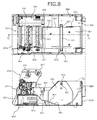
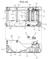
- Figs. 8 , 9 , and 10 are diagrams of an upper aspect and a cross section of the printer 100 of the embodiment according to the present invention.
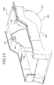
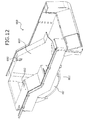
- Figs. 11 and 12 are perspective views of an exterior cover.
- Fig. 6 depicts a state where in the state of the printer 100 depicted in Fig. 2 , the paper 201 held by the paper holding unit 202 has been removed.
- Fig. 7 depicts a state where in the state of the printer 100 depicted in Fig. 3 , the paper 201 held by the paper holding unit 202 has been removed.
- Figs. 8 , 9 , and 10 depict an upper aspect and a cross section of the printer 100 in a state where the upper housing 101b has been removed from the lower housing 101a to expose a portion of the printer main body 400.
- the upper side of Fig. 8 depicts the printer 100 viewed from above, in a state where the upper housing 101b has been removed from the lower housing 101a to expose a portion of the printer main body 400.
- the lower side of Fig. 8 depicts a cross section taken along line C-C in the upper aspect view on the upper side of Fig. 8 .
- Fig. 9 depicts the printer 100 viewed from above, in a state where the upper housing 101b has been removed from the lower housing 101a to expose a portion of the printer main body 400.
- the lower side of Fig. 9 depicts a cross section taken along line D-D in the upper aspect view on the upper side of Fig. 9 .
- Fig. 10 depicts the printer 100 viewed from above, in a state where the upper housing 101b has been removed from the lower housing 101a to expose a portion of the printer main body 400.
- the lower side of Fig. 10 depicts a cross section taken along line E-E in the upper aspect view on the upper side of Fig. 9 .
- an exterior cover 600 that covers the pair of the shaft paper guides 402, 501 is disposed in the housing 101 (the lower housing 101a).
- the exterior cover 600 is formed using an insulating material.
- the exterior cover 600 is attached to the housing 101 (the lower housing 101a) to cover the electrical system components related to the driving of the units included in the printer 100 inside the housing 101 (the lower housing 101a).
- the exterior cover 600 has an opening 601 exposing a surface of the shaft paper guide 501 that is on the side equipped with some of the electrical system components, the surface facing the paper 201 held by the paper holding unit 202.
- the opening 601 opens the cutout portion 501a disposed in the shaft paper guide 501 to the exterior.
- the paper 201 in a wound state and held by the paper holding unit 202 has a side surface allowed to abut the surface of the shaft paper guide exposed from the exterior cover 600 and is thereby positioned in the printer 100.
- the shaft paper guides 402, 501 are formed by sheet-metal working of a metal plate-shaped member having a predetermined thickness and therefore, are formed with high processing accuracy.
- the bottom frame 401 is formed by sheet-metal working of a metal plate-shaped member having a predetermined thickness and therefore, is formed with high processing accuracy. Since the paper 201 is positioned by allowing the side surface of the paper 201 held by the paper holding unit 202 to abut the shaft paper guide 501 fixed to the bottom frame 401, the paper 201 can be positioned precisely in the printer 100.
- the exterior cover 600 further has the opening 602 opening to the exterior, the cutout portion 402a disposed in the shaft paper guide 402 that is on the side without the electrical system components.
- the exterior cover 600 covers the pair of the shaft paper guides 402, 501 with the cutout portions 402a, 501a opened to the exterior through the opening 601 and the opening 602.
- the exterior cover 600 includes a bottom portion 801 and a guiding portion 802.
- the bottom portion 801 forms an arc along the outer diameter of the paper 201 held by the paper holding unit 202.
- the guiding portion 802 is continuous to the bottom portion 801 and is sloped relative to the bottom frame 401 such that a position closer to the paper holding unit 202 is lower from the head unit 203 toward the paper holding unit 202. Since the guiding portion 802 is disposed, even when the paper 201 housed in the housing 101 is pulled toward the head unit 203 during a recording operation, the paper 201 can be restrained from coming closer to the front side while remaining in the roll state.
- the exterior cover 600 includes a side wall portion 603 covering, among the pair of the shaft paper guides 402, 501, the shaft paper guide 402 on the side without the electrical system components.
- the opening 602 is formed by partially cutting out the side wall portion 603.
- the exterior cover 600 is achieved by a single member formed by a method such as injection molding of plastic material.
- the printer 100 of the embodiment according to the present invention includes a housing 101 forming a substantially box shape; and the shaft paper guides 402, 501 acting as a pair of frames disposed in the housing 101 and arranged to oppose each other across the conveyance path of the recording medium; the cutout portions 402a, 501a respectively disposed at the upper ends of the pair of the shaft paper guides 402, 501; and the shaft 403 that while inserted inside the winding core on which the long paper 201 is wound into a roll shape, both ends of the shaft 403 are supported by the cutout portions 402a, 501a, whereby the paper is held while allowing the paper to be pulled out from the housing 101.
- the printer 100 of the present embodiment is characterized by including the exterior cover 600 that is disposed in the housing 101, is formed using an insulating material, has the openings 601, 602 that open the cutout portions 402a, 501a exteriorly, and covers the pair of the shaft paper guides 402, 501 with the cutout portions 402a, 501a opened exteriorly through the openings 601, 602.
- the shaft paper guides 402, 501 acting as a pair of frames can be formed by using a metal material such as a sheet metal member to ensure the strength of the pair of the shaft paper guides 402, 501 and, even when the pair of the shaft paper guides 402, 501 is formed by using a metal material, the pair of the shaft paper guides 402, 501 can be assuredly insulated from the exterior by merely covering the pair of the shaft paper guides 402, 501 with the exterior cover 600 without applying a coating treatment to the pair of the shaft paper guides 402, 501. This enables a reduction in manufacturing costs related to the printer 100 with a strength ensured for holding large diameter roll paper.
- the exterior cover 600 is disposed with the cutout portions 402a, 501a, whereby a configuration enabling both ends of the shaft 403 to be supported by the pair of the shaft paper guides 402, 501 can be easily and assuredly achieved while the pair of the shaft paper guides 402, 501 is insulated from the exterior by merely covering the pair of the shaft paper guides 402, 501 with the exterior cover 600.
- manufacturing man-hours of the printer 100 can be suppressed while the burden placed on the worker for manufacturing the printer 100 is reduced, whereby a reduction in costs related to manufacturing of the printer 100 can be achieved.
- the printer 100 of the embodiment of the present invention includes the electrical system components (such as the control board and power source board not depicted, the interface board 520, the relay board 530, the ribbon board 540, and various cables) disposed in the housing 101 and related to the driving of the units included in the printer 100 and the printer 100 is characterized in that the exterior cover 600 also covers the electrical system components.
- the electrical system components such as the control board and power source board not depicted, the interface board 520, the relay board 530, the ribbon board 540, and various cables
- the printer of the embodiment of the present invention by merely mounting the one exterior cover 600 inside the housing 101, the pair of the shaft paper guides 402, 501 and the electrical system components can be covered and the pair of the shaft paper guides 402, 501 and the electrical system components can be insulated from the exterior.
- manufacturing man-hours of the printer 100 can be suppressed while the burden placed on the worker for manufacturing the printer 100 is reduced, whereby a reduction in costs related to manufacturing of the printer 100 can be achieved.
- the printer according to the present invention is applicable for a printer that uses long paper wound into a roll shape as a recording object and is particularly suitable for a printer that uses large-sized heavy roll paper as a recording object.
Landscapes
- Accessory Devices And Overall Control Thereof (AREA)
- Handling Of Continuous Sheets Of Paper (AREA)
- Unwinding Webs (AREA)
Abstract
Description
- The present invention relates to a printer using large-sized heavy roll paper as a recording object.
- A conventional printer performs a recording operation on a long paper sheet wound into a roll shape (roll paper). When such a printer uses a recording object that is roll paper large in size and heavy consequent to having a large diameter and width in the rolled state, a frame that holds the roll paper is formed of a metal plate-shaped member having a certain thickness so as to ensure the strength of the mechanism holding the roll paper.
- Printers include electrical system components for drive control and power supply to units included in the printer and these electrical system components must be insulated. In the case of a configuration using a metal frame for holding roll paper, the frame must be insulated. Conventionally, for example, arrangement is such that insulation properties of the frame are ensured by coating the metal frame with a paint having high electrical insulation properties.
- Techniques related to a printer using roll paper as a recording object include, for example, a technique of a label printer that is configured to rotatably support a core shaft for mounting a label sheet and has a body core unit that is a cylindrical shape having a first diameter and insertable into a winding core portion of a label sheet and a label sheet mounting unit disposed at a predetermined part in a longitudinal middle portion of the body core unit and having a second diameter that is smaller than the first diameter (see, e.g., Patent Documents 1 and 2).
-
- Patent Document 1:
Japanese Laid-open Patent Publication No. 2008-239259 - Patent Document 2:
Japanese Laid-open Patent Publication No. 2008-284842 - Nonetheless, the conventional techniques described above have the problem of a complicated configuration for insulating electrical system components disposed at multiple positions in the printer. The conventional techniques also have a problem in that the complicated configuration of the printer leads to increased manufacturing man-hours, a large worker burden required for manufacturing, and high manufacturing costs. For example, since the electrical system components are attached in an insulated state and a metal frame coated with a paint having high electrical insulation properties is separately disposed, the conventional techniques have the problems of increased manufacturing man-hours, a large worker burden required for manufacturing, and high manufacturing costs.
- Additionally in the conventional techniques described above, to ensure the insulation properties of the frame, the frame is coated with a paint having high insulation properties, which leads to problems of increased manufacturing man-hours, a large worker burden required for manufacturing, and high manufacturing costs.
- To solve the problems associated with the conventional techniques above, one object of the present invention is to reduce the manufacturing cost of a printer having ensured strength for holding large-diameter roll paper.
- To solve the problems above and achieve an object, a printer according to the present invention includes a housing forming a substantially box shape; a pair of frames disposed in the housing and arranged such that the frames oppose each other across a conveyance path of a recording medium; a cutout portion disposed at an upper end of each of the frames; a shaft that while inserted inside a winding core on which long paper is wound into a roll shape, both ends of the shaft are supported by the cutout portions and the shaft holds the paper while allowing the paper to be pulled out from the housing; and an exterior cover that is disposed in the housing, is formed using an insulating material, has openings that open the cutout portions exteriorly, and covers the pair of the frames with the cutout portions opened exteriorly through the openings.
- The printer according to the invention further includes electrical system components disposed in the housing and related to driving of units included in the printer, where the exterior cover also covers the electrical system components.
- The printer according to the present invention achieves an effect of enabling a reduction in manufacturing costs of a printer having ensured strength for holding large-diameter roll paper.
-
-
Fig. 1 is an explanatory view of the exterior of a printer of an embodiment according to the present invention; -
Fig. 2 is an explanatory view (part 1) of the printer with a housing opened; -
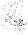
Fig. 3 is an explanatory view (part 2) of the printer with the housing opened; -
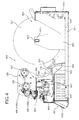
Fig. 4 is a side view (part 1) of a head unit and a printer main body; -
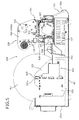
Fig. 5 is a side view (part 2) of the head unit and the printer main body; -
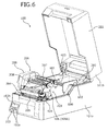
Fig. 6 is an explanatory view (part 1) of the printer with the housing opened; -
Fig. 7 is an explanatory view (part 2) of the printer with the housing opened; -
Fig. 8 is a diagram (part 1) depicting an upper aspect and a cross section of the printer of the embodiment according to the present invention; -
Fig. 9 is a diagram (part 2) depicting an upper aspect and a cross section of the printer of the embodiment according to the present invention; -
Fig. 10 is a diagram (part 3) depicting an upper aspect and a cross section of the printer of the embodiment according to the present invention; -
Fig. 11 is a perspective view (part 1) of an exterior cover; and -
Fig. 12 is a perspective view (part 2) of the exterior cover. - A preferred embodiment of a printer according to the present invention will be described in detail with reference to the accompanying drawings.
- A configuration of a printer of an embodiment according to the present invention will be described.
Fig. 1 is an explanatory view of an exterior of the printer of the embodiment according to the present invention.Fig. 1 depicts the printer of the embodiment according to the present invention in an installed state, viewed obliquely from above. - In
Fig. 1 , aprinter 100 of the embodiment according to the present invention includes ahousing 101 forming a hollow parallelepiped shape. Thehousing 101 includes alower housing 101a having an opening in an upper aspect and forming a substantially box shape, and anupper housing 101b closing the opening of thelower housing 101a in an openable manner. - The
upper housing 101b has an opening in a lower aspect and closes the opening of thelower housing 101a with the opening of the upper housing opposing the opening of thelower housing 101a. Theupper housing 101b is supported about an axis by thelower housing 101a, at a rear aspect of the printer 100 (on the right side ofFig. 1 ) and is thereby rotatably coupled to thelower housing 101a. - With the opening of the
lower housing 101a closed by theupper housing 101b, thehousing 101 forms a housing space that houses a printer main body (seeFigs. 4 and5 ) inside theupper housing 101b and thelower housing 101a. With the opening of thelower housing 101a closed by theupper housing 101b, thehousing 101 forms adischarge port 102 that discharges a recorded recording medium in a front surface (on the left side ofFig. 1 ) of thehousing 101. Thedischarge port 102 is formed in a boundary portion between theupper housing 101b and thelower housing 101a. - On an outer surface of the
housing 101, the front surface of the housing 101 (thelower housing 101a) is equipped with anoperation panel 103. Theoperation panel 103 includesbuttons 103a that receive various input operations and adisplay panel 103b that displays a state, etc. of theprinter 100. - The
display panel 103b displays a given message to report the state of theprinter 100 such as when the printer is powered on and put into a print stand-by state, an error occurs in theprinter 100, or the remaining amount of paper held by theprinter 100 becomes less than or equal to a predetermined amount. Thedisplay panel 103b can be realized by a liquid crystal display, for example. -
Figs. 2 and3 are explanatory views of theprinter 100 with thehousing 101 opened.Fig. 2 depicts theprinter 100 with the inside of thehousing 101 opened exteriorly, as viewed from a position located on the upper right side with respect to the front surface of theprinter 100.Fig. 3 depicts theprinter 100 as viewed from a position located on the upper left side with respect to the front surface of theprinter 100. - In
Figs. 2 and3 , theprinter 100 includes apaper holding unit 202 that, at a rear aspect in the housing 110, holds a recording medium (paper) 201 that is used as a recording object and wound into a roll shape. The recording medium (paper) 201 used as a recording object may be continuous forms wound into a roll shape or may be a label sheet with multiple labels arranged along a longitudinal direction of a mount. - The
printer 100 includes ahead unit 203 disposed closer to the front surface as compared to thepaper holding unit 202 in thehousing 101. A conveyance path is formed inside thehousing 101 from thepaper holding unit 202 via thehead unit 203 to thedischarge port 102. At the time of a recording operation in theprinter 100, thepaper 201 wound into a roll shape held by thepaper holding unit 202 is pulled out from a longitudinal end portion on the outer circumference and conveyed via thehead unit 203 to thedischarge port 102. - The
head unit 203 includes aprint head 204. Theprint head 204 performs a thermal type recording operation, for example. Theprint head 204 that performs a thermal type recording operation includes multiple heating elements arranged in a line along a width direction of the printer 100 (along a direction orthogonal to the conveyance direction of the paper 201). - The
printer 100 selectively energizes the heating elements in the thermal head to selectively cause the heating elements to generate heat and thereby performs the recording operation. Thehead unit 203 may include theprint head 204 of another type of recording instead of the thermal type recording. - In the
housing 101, aplaten 205 is disposed facing theprint head 204 across the conveyance path (thepaper 201 being conveyed through the conveyance path). Theplaten 205 forms a substantially columnar shape having an axial direction that is along the width direction of theprinter 100. At the time of the recording operation, theplaten 205 supports a rear surface of thepaper 201 while a pushing force is applied to a front surface (a recording surface) by theprint head 204. Theprint head 204 is biased in a direction toward theplaten 205. - To one end of an axis of the
platen 205, a motor (seereference numeral 507 ofFig. 5 ) is attached via a gear train not depicted. The gear train rotates by transmitting a drive force of the motor. Theplaten 205 rotates accompanying the rotation of gears making up the gear train. Theplaten 205 rotates and thereby, conveys thepaper 201 in the conveyance path, from thepaper holding unit 202 side toward thedischarge port 102. - The
head unit 203 includes aribbon unit 206 supporting an ink ribbon not depicted. Theribbon unit 206 includes aribbon support shaft 207 supporting the ink ribbon before the ink ribbon is provided for a recording operation and aribbon winding shaft 208 winding the ink ribbon after a recording operation. Theribbon unit 206 also includes a ribbon shaft drive mechanism that rotates theribbon winding shaft 208 to feed the ink ribbon supported by theribbon support shaft 207 and wind the fed ink ribbon around theribbon winding shaft 208. The ribbon shaft drive mechanism is housed in acase 209 and is made up of a motor (seereference numeral 405 ofFig. 5 ), a wheel train that transmits the drive force of the motor to theribbon winding shaft 208, a ribbon board that drives the motor, etc. -
Figs. 4 and5 are side views of thehead unit 203 and the printer main body.Fig. 4 depicts the printer main body with thehousing 101 removed as viewed in the direction indicated by arrow A inFig. 1 .Fig. 5 depicts the printer main body with thehousing 101 removed viewed in the direction indicated by arrow B inFig. 1 .Figs. 4 and5 depict a state in which thecase 209 is removed in theribbon unit 206. - In
Figs. 4 and5 , the printermain body 400 includes abottom frame 401 disposed in thehousing 101. Thebottom frame 401 is formed by sheet-metal working of a metal plate-shaped member having a predetermined thickness. A pair of shaft paper guides 402, 501 realizing a pair of frames is disposed in thebottom frame 401. - The pair of the shaft paper guides 402, 501 is disposed at the position of the
paper holding unit 202 in thehousing 101. The pair of the shaft paper guides 402, 501 is disposed such that the shaft paper guides 402, 501 oppose each other along the width direction of theprinter 100. When thepaper holding unit 202 holds thepaper 201 that is wound into a roll shape, the pair of the shaft paper guides 402, 501 is disposed such that the shaft paper guides 402, 501 oppose each other across thepaper 201, which is wound into a roll shape. -
Cutout portions cutout portions Figs. 4 and5 ). Thecutout portions shaft 403 that holds thepaper 201 that is wound into a roll shape and housed in thepaper holding unit 202, thepaper 201 being held such that thepaper 201 can be pulled out from thepaper holding unit 202. - The
shaft 403 can be realized by a rod-like member having a cross section forming a polygonal shape (e.g., a quadrangular shape). Theshaft 403 is formed by using an insulating material such as a plastic material, for example. Thecutout portions shaft 403. - The ends of the
shaft 403 are respectively fitted into thecutout portions shaft 403 is supported by the pair of the shaft paper guides 402, 501. Theshaft 403 is attached to thepaper holding unit 202 in a detachable manner. Theshaft 403 is removed from thepaper holding unit 202 such as when thepaper 201 is replaced. - The
paper holding unit 202 supports theshaft 403 with the pair of the shaft paper guides 402, 501, theshaft 403 being inserted inside a winding core of thepaper 201 wound into a roll shape. Thereby, thepaper holding unit 202 holds thepaper 201, which is long and wound into a roll shape, such that thepaper 201 can be pulled out from the longitudinal end portion on the outer circumference. Theshaft 403 is inserted inside the winding core without being fixed to the winding core and therefore, supports the winding core of thepaper 201, enabling rotation around theshaft 403. Thus, rotation of the winding core of thepaper 201 around theshaft 403 enables thepaper 201 housed in thepaper holding unit 202 to be pulled out from the longitudinal end portion on the outer circumference. - The shaft paper guides 402, 501 are respectively formed by sheet-metal working of a metal plate-shaped member having a predetermined thickness. Forming the shaft paper guides 402, 501 respectively from a metal plate-shaped member having a predetermined thickness enables the both ends of the
shaft 403 inserted inside the winding core of thepaper 201 to be safely and assuredly supported even when thepaper 201 wound into a roll shape is roll paper having a large diameter and large weight. - The
shaft paper guide 501 of the pair of the shaft paper guides 402, 501 is equipped with adamper mechanism 503. Thedamper mechanism 503 includes adamper shaft 504 swingable in contacting and separating directions with respect to thepaper 201 in the conveyance path. Thedamper shaft 504 is positioned between thepaper holding unit 202 and thehead unit 203 in the conveyance path. - The
damper shaft 504 forms a rod shape having a circular cross section and an axial direction that is the width direction of theprinter 100. One end of thedamper shaft 504 is attached to a tip of adamper arm 505. Thedamper arm 505 is disposed rotatably in a plane formed by theshaft paper guide 501, by using one end coupled to theshaft paper guide 501 as a fulcrum. Thedamper arm 505 rotates by using the one end as a fulcrum, thereby swinging thedamper shaft 504 disposed at the other end in the contacting and separating directions with respect to thepaper 201 in the conveyance path. - The
damper mechanism 503 includes a biasing member (not depicted) biasing thedamper arm 505 in a direction of bringing thedamper shaft 504 into contact with thepaper 201. The biasing member can be realized by a first spring and a second spring (both not shown), for example. - The first spring can be realized by a compression coil spring that compresses the
damper shaft 504 from the upper side to the lower side inFig. 5 . When thedamper arm 505 rotates from the lower side to the upper side, the first spring biases thedamper arm 505 from the upper side to the lower side. - The second spring can be realized by a compression coil spring that compresses the
damper shaft 504 from the lower side to the upper side inFig. 5 . When thedamper arm 505 rotates from the upper side to the lower side, the second spring biases thedamper arm 505 from the lower side to the upper side. - When the
paper 201 held by thepaper holding unit 202 is so-called outward roll paper having a recording surface that is a surface on the outer circumferential side when the paper is wound into a roll shape, thepaper 201 is guided through the conveyance path such that thedamper shaft 504 is brought into contact with thepaper 201 from the lower side inFigs. 4 and5 . When thepaper 201 held by thepaper holding unit 202 is so-called inward roll paper having a recording surface that is a surface on the inner circumferential side when the paper is wound into a roll shape, thepaper 201 is guided through the conveyance path such that thedamper shaft 504 is brought into contact with thepaper 201 from the upper side inFigs. 4 and5 . Thepaper 201 is guided through the conveyance path to come into contact with thedamper shaft 504 between thepaper holding unit 202 and thehead unit 203 and to be bent at the position of the contact. - When a recording operation is started and a conveyance force of the
platen 205 is applied to thepaper 201 in a state in which no recording operation is performed, thepaper 201 is pulled in a stretched manner between theplaten 205 and thepaper holding unit 202 by an inertia force due to the weight of thepaper 201 wound into a roll shape in thepaper holding unit 202. In particular, since the conveyance force of theplaten 205 is applied to thepaper 201 while the inertia force tending to maintain a stopped state is acting due to the weight of thepaper 201 wound into a roll shape in thepaper holding unit 202, a conveyance force toward thedischarge port 102 is momentarily applied to thepaper 201 on the side closer to theplaten 205 even though thepaper 201 is stopped on the side of thepaper holding unit 202. As a result, thepaper 201 is pulled in a linearly stretched manner between theplaten 205 and thepaper holding unit 202. - Since the
damper mechanism 503 includes the biasing member that biases thedamper arm 505 in the direction of bringing thedamper shaft 504 into contact with thepaper 201, when thepaper 201 is pulled in a linearly stretched manner, thedamper mechanism 503 causes thedamper shaft 504 to resiliently contact thepaper 201 and bias thepaper 201 in a bending direction. As a result, since the stretching of thepaper 201 can be buffered to alleviate impact (inertia force) on thepaper 201, thepaper 201 can be conveyed with precision and a constant feed rate of thepaper 201 can be achieved regardless of whether thepaper 201 is outward roll paper or inward roll paper. - The
ribbon unit 206 includes a pair of ribbon frames 406 (406a, 406b) supporting theribbon support shaft 207 and theribbon winding shaft 208. The ribbon frames 406 (406a, 406b) support theribbon support shaft 207 and theribbon winding shaft 208 at both axial end positions of theribbon support shaft 207 and theribbon winding shaft 208 such that theribbon support shaft 207 and theribbon winding shaft 208 are rotatable around axial centers. - The printer
main body 400 includes electrical system components providing drive control to the units included in theprinter 100. The electrical system components include a control board (not depicted), a power source board (not depicted), aninterface board 520, arelay board 530, aribbon board 540, and various cables. - The control board is disposed in a standing manner and is fixed to a bracket (not depicted) that is fixed to the
bottom frame 401 outside theshaft paper guide 501. The control board includes a CPU, memory, etc. providing energization control of theprint head 204, drive control of themotor 507 that drives theplaten 205, drive control of a motor that drives theribbon support shaft 207 and theribbon winding shaft 208, etc. - The power source board is connected to the control board. The power source board is located under the
head unit 203. The power source board is connected to the control board via a cable (not depicted) that is connected to a connector (not depicted) included in the power source board. The power source board provides a power source to the control board via the cable connecting between the power source board and the control board. - The
interface board 520 is connected to the control board via a connector. Theinterface board 520 includes an interface connector (not depicted) that is connected to an external device. The interface connector is attached via an opening (not
depicted) disposed in thelower housing 101a such that the interface connector is exposed externally, from a rear aspect of thelower housing 101a. - The
relay board 530 is disposed on a left side portion between thehead unit 203 and thepaper holding unit 202. Therelay board 530 is fixed onto abracket 407 that is fixed to thebottom frame 401. Therelay board 530 is connected to the control board via a cable not depicted. - The
ribbon board 540 is attached to theribbon frame 406a. Theribbon board 540 is connected to themotor 405 that drives theribbon support shaft 207 and theribbon winding shaft 208 as well as a ribbon rotation detection sensor and a ribbon tension sensor (both not depicted). Theribbon board 540 is connected via acable 506 to aconnector 531 of therelay board 530. - The
cable 506 is fixed to acable supporting member 508 disposed on theribbon frame 406a between therelay board 530 and theribbon board 540. Thecable supporting member 508 is disposed projecting from the lower end of theribbon frame 406a to a position on a rotation center axis of thehead unit 203 relative to the printermain body 400 or in the vicinity of the rotation center axis. - By fixing the
cable 506 to a position on the rotation center axis of thehead unit 203 relative to the printermain body 400 or in the vicinity of the rotation center axis, thecable 506 can be restrained from being damaged because of pulling and rubbing due to the rotation of thehead unit 203. Thecable supporting member 508 may be used for fixing not only thecable 506 but also other cables supplying electricity and outputting control signals to theprint head 204 included in thehead unit 203 and various sensors such as a sensor detecting a position of thepaper 201. - The
ribbon board 540 receives the power source supplied from the control board and the control signals output from the control board via therelay board 530 and is thereby driven by the control board. Theribbon board 540 may be provided with connectors connecting cables for controlling a paper cutter, a peeler (a peeling mechanism), etc. (all not depicted). - The
head unit 203 is rotatably coupled to the printermain body 400 via a shaft (not depicted) having an axial direction that is a direction parallel to the conveyance direction of thepaper 201 conveyed through the conveyance path (the longitudinal direction of the paper 201). The printermain body 400 is equipped with a lock mechanism (not depicted) locking thehead unit 203 such that thehead unit 203 is fixed to the printermain body 400. The printermain body 400 is equipped with alock release lever 404 that releases the locking of the lock mechanism. Thelock release lever 404 is rotatably coupled to the printermain body 400. - The
lock release lever 404 is biased from the rear toward the front of theprinter 100 and is positioned at an anterior aspect to lock thehead unit 203 in a fixed state to the printermain body 400. The locking of the lock mechanism is released by rotating thelock release lever 404 in a direction from the front toward the back of theprinter 100. Manipulation of the printermain body 400, thehead unit 203, and thelock release lever 404 are enabled in theprinter 100 when theupper housing 101b is rotated relative to thelower housing 101a to open the housing space exteriorly. - The pair of the ribbon frames 406 in the
head unit 203 supports the ends of theribbon support shaft 207 and theribbon winding shaft 208 such that theribbon support shaft 207 and theribbon winding shaft 208 are rotatable. The pair of the ribbon frames 406 is integrally formed by sheet-metal working of a metal plate-shaped member having a predetermined thickness. Themotor 405 that rotates theribbon winding shaft 208 is disposed on theribbon frame 406a of the pair of the ribbon frames 406.Figs. 4 and5 depict a state with thecase 209 removed. -
Figs. 6 and7 are explanatory views of theprinter 100 with thehousing 101 opened.Figs. 8 ,9 , and10 are diagrams of an upper aspect and a cross section of theprinter 100 of the embodiment according to the present invention.Figs. 11 and12 are perspective views of an exterior cover. -
Fig. 6 depicts a state where in the state of theprinter 100 depicted inFig. 2 , thepaper 201 held by thepaper holding unit 202 has been removed.Fig. 7 depicts a state where in the state of theprinter 100 depicted inFig. 3 , thepaper 201 held by thepaper holding unit 202 has been removed.Figs. 8 ,9 , and10 depict an upper aspect and a cross section of theprinter 100 in a state where theupper housing 101b has been removed from thelower housing 101a to expose a portion of the printermain body 400. - The upper side of
Fig. 8 depicts theprinter 100 viewed from above, in a state where theupper housing 101b has been removed from thelower housing 101a to expose a portion of the printermain body 400. The lower side ofFig. 8 depicts a cross section taken along line C-C in the upper aspect view on the upper side ofFig. 8 . - The upper side of
Fig. 9 depicts theprinter 100 viewed from above, in a state where theupper housing 101b has been removed from thelower housing 101a to expose a portion of the printermain body 400. The lower side ofFig. 9 depicts a cross section taken along line D-D in the upper aspect view on the upper side ofFig. 9 . - The upper side of
Fig. 10 depicts theprinter 100 viewed from above, in a state where theupper housing 101b has been removed from thelower housing 101a to expose a portion of the printermain body 400. The lower side ofFig. 10 depicts a cross section taken along line E-E in the upper aspect view on the upper side ofFig. 9 . - In
Figs. 6 ,7 ,8 ,9 ,10 ,11 , and12 , anexterior cover 600 that covers the pair of the shaft paper guides 402, 501 is disposed in the housing 101 (thelower housing 101a). Theexterior cover 600 is formed using an insulating material. Theexterior cover 600 is attached to the housing 101 (thelower housing 101a) to cover the electrical system components related to the driving of the units included in theprinter 100 inside the housing 101 (thelower housing 101a). - The
exterior cover 600 has anopening 601 exposing a surface of theshaft paper guide 501 that is on the side equipped with some of the electrical system components, the surface facing thepaper 201 held by thepaper holding unit 202. Theopening 601 opens thecutout portion 501a disposed in theshaft paper guide 501 to the exterior. Thepaper 201 in a wound state and held by thepaper holding unit 202 has a side surface allowed to abut the surface of the shaft paper guide exposed from theexterior cover 600 and is thereby positioned in theprinter 100. - As described above, the shaft paper guides 402, 501 are formed by sheet-metal working of a metal plate-shaped member having a predetermined thickness and therefore, are formed with high processing accuracy. Similarly, the
bottom frame 401 is formed by sheet-metal working of a metal plate-shaped member having a predetermined thickness and therefore, is formed with high processing accuracy. Since thepaper 201 is positioned by allowing the side surface of thepaper 201 held by thepaper holding unit 202 to abut theshaft paper guide 501 fixed to thebottom frame 401, thepaper 201 can be positioned precisely in theprinter 100. - The
exterior cover 600 further has theopening 602 opening to the exterior, thecutout portion 402a disposed in theshaft paper guide 402 that is on the side without the electrical system components. When attached to the housing 101 (thelower housing 101a), theexterior cover 600 covers the pair of the shaft paper guides 402, 501 with thecutout portions opening 601 and theopening 602. Theexterior cover 600 includes abottom portion 801 and a guidingportion 802. Thebottom portion 801 forms an arc along the outer diameter of thepaper 201 held by thepaper holding unit 202. - The guiding
portion 802 is continuous to thebottom portion 801 and is sloped relative to thebottom frame 401 such that a position closer to thepaper holding unit 202 is lower from thehead unit 203 toward thepaper holding unit 202. Since the guidingportion 802 is disposed, even when thepaper 201 housed in thehousing 101 is pulled toward thehead unit 203 during a recording operation, thepaper 201 can be restrained from coming closer to the front side while remaining in the roll state. - The
exterior cover 600 includes aside wall portion 603 covering, among the pair of the shaft paper guides 402, 501, theshaft paper guide 402 on the side without the electrical system components. Theopening 602 is formed by partially cutting out theside wall portion 603. As depicted inFigs. 11 and12 , theexterior cover 600 is achieved by a single member formed by a method such as injection molding of plastic material. - As described above, the
printer 100 of the embodiment according to the present invention includes ahousing 101 forming a substantially box shape; and the shaft paper guides 402, 501 acting as a pair of frames disposed in thehousing 101 and arranged to oppose each other across the conveyance path of the recording medium; thecutout portions shaft 403 that while inserted inside the winding core on which thelong paper 201 is wound into a roll shape, both ends of theshaft 403 are supported by thecutout portions housing 101. Theprinter 100 of the present embodiment is characterized by including theexterior cover 600 that is disposed in thehousing 101, is formed using an insulating material, has theopenings cutout portions cutout portions openings - According to the
printer 100 of the embodiment of the present invention, the shaft paper guides 402, 501 acting as a pair of frames can be formed by using a metal material such as a sheet metal member to ensure the strength of the pair of the shaft paper guides 402, 501 and, even when the pair of the shaft paper guides 402, 501 is formed by using a metal material, the pair of the shaft paper guides 402, 501 can be assuredly insulated from the exterior by merely covering the pair of the shaft paper guides 402, 501 with theexterior cover 600 without applying a coating treatment to the pair of the shaft paper guides 402, 501. This enables a reduction in manufacturing costs related to theprinter 100 with a strength ensured for holding large diameter roll paper. - According to the
printer 100 of the embodiment of the present invention, theexterior cover 600 is disposed with thecutout portions shaft 403 to be supported by the pair of the shaft paper guides 402, 501 can be easily and assuredly achieved while the pair of the shaft paper guides 402, 501 is insulated from the exterior by merely covering the pair of the shaft paper guides 402, 501 with theexterior cover 600. Thus, manufacturing man-hours of theprinter 100 can be suppressed while the burden placed on the worker for manufacturing theprinter 100 is reduced, whereby a reduction in costs related to manufacturing of theprinter 100 can be achieved. - The
printer 100 of the embodiment of the present invention includes the electrical system components (such as the control board and power source board not depicted, theinterface board 520, therelay board 530, theribbon board 540, and various cables) disposed in thehousing 101 and related to the driving of the units included in theprinter 100 and theprinter 100 is characterized in that theexterior cover 600 also covers the electrical system components. - According to the printer of the embodiment of the present invention, by merely mounting the one
exterior cover 600 inside thehousing 101, the pair of the shaft paper guides 402, 501 and the electrical system components can be covered and the pair of the shaft paper guides 402, 501 and the electrical system components can be insulated from the exterior. Thus, manufacturing man-hours of theprinter 100 can be suppressed while the burden placed on the worker for manufacturing theprinter 100 is reduced, whereby a reduction in costs related to manufacturing of theprinter 100 can be achieved. - As described above, the printer according to the present invention is applicable for a printer that uses long paper wound into a roll shape as a recording object and is particularly suitable for a printer that uses large-sized heavy roll paper as a recording object.
-
- 100
- printer
- 202
- paper holding unit
- 402, 501
- shaft paper guide
- 402a, 501a
- cutout portion
- 600
- exterior cover
- 601, 602
- opening
- 603
- side wall portion
- 801
- bottom portion
- 802
- guiding portion
Claims (2)
- A printer comprising:a housing forming a substantially box shape;a pair of frames disposed in the housing and arranged such that the frames oppose each other across a conveyance path of a recording medium;a cutout portion disposed at an upper end of each of the frames;a shaft that while inserted inside a winding core on which long paper is wound into a roll shape, both ends of the shaft are supported by the cutout portions and the shaft holds the paper while allowing the paper to be pulled out from the housing; andan exterior cover that is disposed in the housing, is formed using an insulating material, has openings that open the cutout portions exteriorly, and covers the pair of the frames with the cutout portions opened exteriorly through the openings.
- The printer according to claim 1, further comprising
electrical system components disposed in the housing and related to driving of units included in the printer, wherein
the exterior cover also covers the electrical system components.
Applications Claiming Priority (2)
| Application Number | Priority Date | Filing Date | Title |
|---|---|---|---|
| JP2014071554A JP5865934B2 (en) | 2014-03-31 | 2014-03-31 | Printer |
| PCT/JP2014/084191 WO2015151360A1 (en) | 2014-03-31 | 2014-12-24 | Printer |
Publications (3)
| Publication Number | Publication Date |
|---|---|
| EP3064363A1 true EP3064363A1 (en) | 2016-09-07 |
| EP3064363A4 EP3064363A4 (en) | 2017-07-19 |
| EP3064363B1 EP3064363B1 (en) | 2018-10-24 |
Family
ID=54239717
Family Applications (1)
| Application Number | Title | Priority Date | Filing Date |
|---|---|---|---|
| EP14888170.9A Not-in-force EP3064363B1 (en) | 2014-03-31 | 2014-12-24 | Printer |
Country Status (5)
| Country | Link |
|---|---|
| US (1) | US9597907B2 (en) |
| EP (1) | EP3064363B1 (en) |
| JP (1) | JP5865934B2 (en) |
| CN (1) | CN105793053B (en) |
| WO (1) | WO2015151360A1 (en) |
Families Citing this family (7)
| Publication number | Priority date | Publication date | Assignee | Title |
|---|---|---|---|---|
| JP6926397B2 (en) * | 2016-03-31 | 2021-08-25 | セイコーエプソン株式会社 | Printing equipment |
| USD832313S1 (en) * | 2016-05-09 | 2018-10-30 | Hewlett-Packard Development Company, L.P. | Three dimensional printing material container |
| JP1565353S (en) * | 2016-05-25 | 2019-11-25 | ||
| USD801401S1 (en) * | 2016-05-25 | 2017-10-31 | Xerox Corporation | Printing machine |
| GB2559404A (en) | 2017-02-06 | 2018-08-08 | Dover Europe Sarl | A printing apparatus |
| CN107244577B (en) * | 2017-08-01 | 2023-12-22 | 南通恒绮纺织有限公司 | Convenient cutting type cotton cloth structure |
| USD888822S1 (en) * | 2019-01-02 | 2020-06-30 | Ncr Corporation | Printer |
Family Cites Families (16)
| Publication number | Priority date | Publication date | Assignee | Title |
|---|---|---|---|---|
| DE69734686T2 (en) * | 1996-03-06 | 2006-07-27 | Seiko Epson Corp. | Paper roll holder for a printer |
| JP3644823B2 (en) * | 1998-06-30 | 2005-05-11 | 東芝テック株式会社 | Receipt printer |
| JP2001341856A (en) * | 2000-05-30 | 2001-12-11 | Canon Inc | Sheet feeding apparatus and image forming apparatus |
| JP4175785B2 (en) * | 2001-03-30 | 2008-11-05 | 株式会社リコー | Falling part receiving structure and image forming apparatus having the same |
| JP4117498B2 (en) * | 2006-08-01 | 2008-07-16 | セイコーエプソン株式会社 | Printer |
| JP2008239259A (en) * | 2007-03-23 | 2008-10-09 | Max Co Ltd | Label printer |
| JP2008284842A (en) * | 2007-05-21 | 2008-11-27 | Max Co Ltd | Label printer |
| JP2009169126A (en) * | 2008-01-17 | 2009-07-30 | Kyocera Mita Corp | Image forming apparatus |
| US7967516B2 (en) * | 2008-02-25 | 2011-06-28 | Avery Dennison Corporation | Portable printer and methods |
| JP5270321B2 (en) * | 2008-12-05 | 2013-08-21 | 富士通コンポーネント株式会社 | Printer module |
| JP5293272B2 (en) * | 2009-03-02 | 2013-09-18 | セイコーエプソン株式会社 | printer |
| JP5001324B2 (en) * | 2009-03-30 | 2012-08-15 | シチズンホールディングス株式会社 | Printer |
| US8585305B2 (en) * | 2010-02-02 | 2013-11-19 | Seiko Instruments Inc. | Printer |
| JP5576138B2 (en) * | 2010-02-10 | 2014-08-20 | シチズンホールディングス株式会社 | Thermal printer |
| JP2012116572A (en) * | 2010-11-29 | 2012-06-21 | Seiko Epson Corp | Tape route maintaining mechanism, tape cartridge, and tape printer |
| JP5737574B2 (en) * | 2011-06-03 | 2015-06-17 | ブラザー工業株式会社 | Electronics |
-
2014
- 2014-03-31 JP JP2014071554A patent/JP5865934B2/en not_active Expired - Fee Related
- 2014-12-24 CN CN201480062607.0A patent/CN105793053B/en not_active Expired - Fee Related
- 2014-12-24 WO PCT/JP2014/084191 patent/WO2015151360A1/en not_active Ceased
- 2014-12-24 EP EP14888170.9A patent/EP3064363B1/en not_active Not-in-force
-
2016
- 2016-05-02 US US15/144,253 patent/US9597907B2/en not_active Expired - Fee Related
Also Published As
| Publication number | Publication date |
|---|---|
| US9597907B2 (en) | 2017-03-21 |
| JP2015193107A (en) | 2015-11-05 |
| US20160243865A1 (en) | 2016-08-25 |
| JP5865934B2 (en) | 2016-02-17 |
| CN105793053B (en) | 2019-06-28 |
| EP3064363B1 (en) | 2018-10-24 |
| EP3064363A4 (en) | 2017-07-19 |
| CN105793053A (en) | 2016-07-20 |
| WO2015151360A1 (en) | 2015-10-08 |
Similar Documents
| Publication | Publication Date | Title |
|---|---|---|
| US9597907B2 (en) | Printer | |
| EP2634104B1 (en) | Labeling device | |
| US8425131B2 (en) | Printing apparatus and roll paper holding apparatus | |
| JP4763577B2 (en) | Roll paper support mechanism and printer | |
| US11654695B2 (en) | Printing system | |
| CN107323108A (en) | Paper feed, stripping servicing unit and printer | |
| JP2010105811A (en) | Printer and roll paper holding mechanism | |
| US9597902B2 (en) | Printer | |
| JP5313313B2 (en) | Printing device | |
| WO2017043361A1 (en) | Printer | |
| US9205692B2 (en) | Ink ribbon cassette and printing device | |
| JPH10100493A (en) | Mounting device for cutter unit | |
| JP2015193109A (en) | printer | |
| EP3437885A1 (en) | Printer | |
| JP2015193108A (en) | printer | |
| JP4824783B2 (en) | Label printer | |
| JP2007276491A (en) | Portable printer apparatus | |
| JP5286401B2 (en) | Label printer | |
| US10946677B2 (en) | Printer | |
| JP4837753B2 (en) | Printing device | |
| JP2002019208A (en) | Printer device | |
| JP6358177B2 (en) | Printing device | |
| JP2023097195A (en) | Cutter unit and image recording device | |
| JP2015163450A (en) | printer | |
| JPH10310291A (en) | Roll paper supply device |
Legal Events
| Date | Code | Title | Description |
|---|---|---|---|
| PUAI | Public reference made under article 153(3) epc to a published international application that has entered the european phase |
Free format text: ORIGINAL CODE: 0009012 |
|
| 17P | Request for examination filed |
Effective date: 20160511 |
|
| AK | Designated contracting states |
Kind code of ref document: A1 Designated state(s): AL AT BE BG CH CY CZ DE DK EE ES FI FR GB GR HR HU IE IS IT LI LT LU LV MC MK MT NL NO PL PT RO RS SE SI SK SM TR |
|
| AX | Request for extension of the european patent |
Extension state: BA ME |
|
| RAP1 | Party data changed (applicant data changed or rights of an application transferred) |
Owner name: CITIZEN WATCH CO., LTD. Owner name: CITIZEN SYSTEMS JAPAN CO., LTD. |
|
| DAX | Request for extension of the european patent (deleted) | ||
| A4 | Supplementary search report drawn up and despatched |
Effective date: 20170619 |
|
| RIC1 | Information provided on ipc code assigned before grant |
Ipc: B41J 15/04 20060101AFI20170612BHEP Ipc: B65H 16/06 20060101ALI20170612BHEP |
|
| GRAP | Despatch of communication of intention to grant a patent |
Free format text: ORIGINAL CODE: EPIDOSNIGR1 |
|
| STAA | Information on the status of an ep patent application or granted ep patent |
Free format text: STATUS: GRANT OF PATENT IS INTENDED |
|
| INTG | Intention to grant announced |
Effective date: 20180507 |
|
| GRAS | Grant fee paid |
Free format text: ORIGINAL CODE: EPIDOSNIGR3 |
|
| GRAA | (expected) grant |
Free format text: ORIGINAL CODE: 0009210 |
|
| STAA | Information on the status of an ep patent application or granted ep patent |
Free format text: STATUS: THE PATENT HAS BEEN GRANTED |
|
| AK | Designated contracting states |
Kind code of ref document: B1 Designated state(s): AL AT BE BG CH CY CZ DE DK EE ES FI FR GB GR HR HU IE IS IT LI LT LU LV MC MK MT NL NO PL PT RO RS SE SI SK SM TR |
|
| REG | Reference to a national code |
Ref country code: CH Ref legal event code: EP |
|
| REG | Reference to a national code |
Ref country code: IE Ref legal event code: FG4D |
|
| REG | Reference to a national code |
Ref country code: AT Ref legal event code: REF Ref document number: 1056210 Country of ref document: AT Kind code of ref document: T Effective date: 20181115 |
|
| REG | Reference to a national code |
Ref country code: DE Ref legal event code: R096 Ref document number: 602014034902 Country of ref document: DE |
|
| REG | Reference to a national code |
Ref country code: NL Ref legal event code: MP Effective date: 20181024 |
|
| REG | Reference to a national code |
Ref country code: LT Ref legal event code: MG4D |
|
| REG | Reference to a national code |
Ref country code: AT Ref legal event code: MK05 Ref document number: 1056210 Country of ref document: AT Kind code of ref document: T Effective date: 20181024 |
|
| PG25 | Lapsed in a contracting state [announced via postgrant information from national office to epo] |
Ref country code: NL Free format text: LAPSE BECAUSE OF FAILURE TO SUBMIT A TRANSLATION OF THE DESCRIPTION OR TO PAY THE FEE WITHIN THE PRESCRIBED TIME-LIMIT Effective date: 20181024 |
|
| PG25 | Lapsed in a contracting state [announced via postgrant information from national office to epo] |
Ref country code: ES Free format text: LAPSE BECAUSE OF FAILURE TO SUBMIT A TRANSLATION OF THE DESCRIPTION OR TO PAY THE FEE WITHIN THE PRESCRIBED TIME-LIMIT Effective date: 20181024 Ref country code: AT Free format text: LAPSE BECAUSE OF FAILURE TO SUBMIT A TRANSLATION OF THE DESCRIPTION OR TO PAY THE FEE WITHIN THE PRESCRIBED TIME-LIMIT Effective date: 20181024 Ref country code: IS Free format text: LAPSE BECAUSE OF FAILURE TO SUBMIT A TRANSLATION OF THE DESCRIPTION OR TO PAY THE FEE WITHIN THE PRESCRIBED TIME-LIMIT Effective date: 20190224 Ref country code: NO Free format text: LAPSE BECAUSE OF FAILURE TO SUBMIT A TRANSLATION OF THE DESCRIPTION OR TO PAY THE FEE WITHIN THE PRESCRIBED TIME-LIMIT Effective date: 20190124 Ref country code: BG Free format text: LAPSE BECAUSE OF FAILURE TO SUBMIT A TRANSLATION OF THE DESCRIPTION OR TO PAY THE FEE WITHIN THE PRESCRIBED TIME-LIMIT Effective date: 20190124 Ref country code: PL Free format text: LAPSE BECAUSE OF FAILURE TO SUBMIT A TRANSLATION OF THE DESCRIPTION OR TO PAY THE FEE WITHIN THE PRESCRIBED TIME-LIMIT Effective date: 20181024 Ref country code: HR Free format text: LAPSE BECAUSE OF FAILURE TO SUBMIT A TRANSLATION OF THE DESCRIPTION OR TO PAY THE FEE WITHIN THE PRESCRIBED TIME-LIMIT Effective date: 20181024 Ref country code: FI Free format text: LAPSE BECAUSE OF FAILURE TO SUBMIT A TRANSLATION OF THE DESCRIPTION OR TO PAY THE FEE WITHIN THE PRESCRIBED TIME-LIMIT Effective date: 20181024 Ref country code: LT Free format text: LAPSE BECAUSE OF FAILURE TO SUBMIT A TRANSLATION OF THE DESCRIPTION OR TO PAY THE FEE WITHIN THE PRESCRIBED TIME-LIMIT Effective date: 20181024 Ref country code: LV Free format text: LAPSE BECAUSE OF FAILURE TO SUBMIT A TRANSLATION OF THE DESCRIPTION OR TO PAY THE FEE WITHIN THE PRESCRIBED TIME-LIMIT Effective date: 20181024 |
|
| PG25 | Lapsed in a contracting state [announced via postgrant information from national office to epo] |
Ref country code: SE Free format text: LAPSE BECAUSE OF FAILURE TO SUBMIT A TRANSLATION OF THE DESCRIPTION OR TO PAY THE FEE WITHIN THE PRESCRIBED TIME-LIMIT Effective date: 20181024 Ref country code: RS Free format text: LAPSE BECAUSE OF FAILURE TO SUBMIT A TRANSLATION OF THE DESCRIPTION OR TO PAY THE FEE WITHIN THE PRESCRIBED TIME-LIMIT Effective date: 20181024 Ref country code: AL Free format text: LAPSE BECAUSE OF FAILURE TO SUBMIT A TRANSLATION OF THE DESCRIPTION OR TO PAY THE FEE WITHIN THE PRESCRIBED TIME-LIMIT Effective date: 20181024 Ref country code: PT Free format text: LAPSE BECAUSE OF FAILURE TO SUBMIT A TRANSLATION OF THE DESCRIPTION OR TO PAY THE FEE WITHIN THE PRESCRIBED TIME-LIMIT Effective date: 20190224 Ref country code: GR Free format text: LAPSE BECAUSE OF FAILURE TO SUBMIT A TRANSLATION OF THE DESCRIPTION OR TO PAY THE FEE WITHIN THE PRESCRIBED TIME-LIMIT Effective date: 20190125 |
|
| REG | Reference to a national code |
Ref country code: DE Ref legal event code: R097 Ref document number: 602014034902 Country of ref document: DE |
|
| PG25 | Lapsed in a contracting state [announced via postgrant information from national office to epo] |
Ref country code: DK Free format text: LAPSE BECAUSE OF FAILURE TO SUBMIT A TRANSLATION OF THE DESCRIPTION OR TO PAY THE FEE WITHIN THE PRESCRIBED TIME-LIMIT Effective date: 20181024 Ref country code: IT Free format text: LAPSE BECAUSE OF FAILURE TO SUBMIT A TRANSLATION OF THE DESCRIPTION OR TO PAY THE FEE WITHIN THE PRESCRIBED TIME-LIMIT Effective date: 20181024 Ref country code: CZ Free format text: LAPSE BECAUSE OF FAILURE TO SUBMIT A TRANSLATION OF THE DESCRIPTION OR TO PAY THE FEE WITHIN THE PRESCRIBED TIME-LIMIT Effective date: 20181024 |
|
| REG | Reference to a national code |
Ref country code: CH Ref legal event code: PL |
|
| PG25 | Lapsed in a contracting state [announced via postgrant information from national office to epo] |
Ref country code: SM Free format text: LAPSE BECAUSE OF FAILURE TO SUBMIT A TRANSLATION OF THE DESCRIPTION OR TO PAY THE FEE WITHIN THE PRESCRIBED TIME-LIMIT Effective date: 20181024 Ref country code: EE Free format text: LAPSE BECAUSE OF FAILURE TO SUBMIT A TRANSLATION OF THE DESCRIPTION OR TO PAY THE FEE WITHIN THE PRESCRIBED TIME-LIMIT Effective date: 20181024 Ref country code: RO Free format text: LAPSE BECAUSE OF FAILURE TO SUBMIT A TRANSLATION OF THE DESCRIPTION OR TO PAY THE FEE WITHIN THE PRESCRIBED TIME-LIMIT Effective date: 20181024 Ref country code: LU Free format text: LAPSE BECAUSE OF NON-PAYMENT OF DUE FEES Effective date: 20181224 Ref country code: MC Free format text: LAPSE BECAUSE OF FAILURE TO SUBMIT A TRANSLATION OF THE DESCRIPTION OR TO PAY THE FEE WITHIN THE PRESCRIBED TIME-LIMIT Effective date: 20181024 Ref country code: SK Free format text: LAPSE BECAUSE OF FAILURE TO SUBMIT A TRANSLATION OF THE DESCRIPTION OR TO PAY THE FEE WITHIN THE PRESCRIBED TIME-LIMIT Effective date: 20181024 |
|
| PLBE | No opposition filed within time limit |
Free format text: ORIGINAL CODE: 0009261 |
|
| STAA | Information on the status of an ep patent application or granted ep patent |
Free format text: STATUS: NO OPPOSITION FILED WITHIN TIME LIMIT |
|
| REG | Reference to a national code |
Ref country code: IE Ref legal event code: MM4A |
|
| GBPC | Gb: european patent ceased through non-payment of renewal fee |
Effective date: 20190124 |
|
| 26N | No opposition filed |
Effective date: 20190725 |
|
| REG | Reference to a national code |
Ref country code: BE Ref legal event code: MM Effective date: 20181231 |
|
| PG25 | Lapsed in a contracting state [announced via postgrant information from national office to epo] |
Ref country code: IE Free format text: LAPSE BECAUSE OF NON-PAYMENT OF DUE FEES Effective date: 20181224 Ref country code: FR Free format text: LAPSE BECAUSE OF NON-PAYMENT OF DUE FEES Effective date: 20181224 Ref country code: SI Free format text: LAPSE BECAUSE OF FAILURE TO SUBMIT A TRANSLATION OF THE DESCRIPTION OR TO PAY THE FEE WITHIN THE PRESCRIBED TIME-LIMIT Effective date: 20181024 |
|
| PG25 | Lapsed in a contracting state [announced via postgrant information from national office to epo] |
Ref country code: BE Free format text: LAPSE BECAUSE OF NON-PAYMENT OF DUE FEES Effective date: 20181231 |
|
| PG25 | Lapsed in a contracting state [announced via postgrant information from national office to epo] |
Ref country code: LI Free format text: LAPSE BECAUSE OF NON-PAYMENT OF DUE FEES Effective date: 20181231 Ref country code: GB Free format text: LAPSE BECAUSE OF NON-PAYMENT OF DUE FEES Effective date: 20190124 Ref country code: CH Free format text: LAPSE BECAUSE OF NON-PAYMENT OF DUE FEES Effective date: 20181231 |
|
| PG25 | Lapsed in a contracting state [announced via postgrant information from national office to epo] |
Ref country code: MT Free format text: LAPSE BECAUSE OF NON-PAYMENT OF DUE FEES Effective date: 20181224 |
|
| PGFP | Annual fee paid to national office [announced via postgrant information from national office to epo] |
Ref country code: DE Payment date: 20191210 Year of fee payment: 6 |
|
| PG25 | Lapsed in a contracting state [announced via postgrant information from national office to epo] |
Ref country code: TR Free format text: LAPSE BECAUSE OF FAILURE TO SUBMIT A TRANSLATION OF THE DESCRIPTION OR TO PAY THE FEE WITHIN THE PRESCRIBED TIME-LIMIT Effective date: 20181024 |
|
| PG25 | Lapsed in a contracting state [announced via postgrant information from national office to epo] |
Ref country code: MK Free format text: LAPSE BECAUSE OF NON-PAYMENT OF DUE FEES Effective date: 20181024 Ref country code: CY Free format text: LAPSE BECAUSE OF FAILURE TO SUBMIT A TRANSLATION OF THE DESCRIPTION OR TO PAY THE FEE WITHIN THE PRESCRIBED TIME-LIMIT Effective date: 20181024 Ref country code: HU Free format text: LAPSE BECAUSE OF FAILURE TO SUBMIT A TRANSLATION OF THE DESCRIPTION OR TO PAY THE FEE WITHIN THE PRESCRIBED TIME-LIMIT; INVALID AB INITIO Effective date: 20141224 |
|
| REG | Reference to a national code |
Ref country code: DE Ref legal event code: R119 Ref document number: 602014034902 Country of ref document: DE |
|
| PG25 | Lapsed in a contracting state [announced via postgrant information from national office to epo] |
Ref country code: DE Free format text: LAPSE BECAUSE OF NON-PAYMENT OF DUE FEES Effective date: 20210701 |