EP3064337A1 - Thermoplastic truss structure for use in wing and rotor blade structures and methods for manufacture - Google Patents
Thermoplastic truss structure for use in wing and rotor blade structures and methods for manufacture Download PDFInfo
- Publication number
- EP3064337A1 EP3064337A1 EP16155999.2A EP16155999A EP3064337A1 EP 3064337 A1 EP3064337 A1 EP 3064337A1 EP 16155999 A EP16155999 A EP 16155999A EP 3064337 A1 EP3064337 A1 EP 3064337A1
- Authority
- EP
- European Patent Office
- Prior art keywords
- wire segment
- wire
- segment
- dimensional
- thermoplastic
- Prior art date
- Legal status (The legal status is an assumption and is not a legal conclusion. Google has not performed a legal analysis and makes no representation as to the accuracy of the status listed.)
- Granted
Links
- 229920001169 thermoplastic Polymers 0.000 title claims abstract description 36
- 239000004416 thermosoftening plastic Substances 0.000 title claims abstract description 36
- 238000000034 method Methods 0.000 title claims abstract description 27
- 238000004519 manufacturing process Methods 0.000 title description 3
- 239000012815 thermoplastic material Substances 0.000 claims abstract description 30
- 239000000835 fiber Substances 0.000 claims abstract description 13
- 230000004927 fusion Effects 0.000 claims description 5
- 229920005992 thermoplastic resin Polymers 0.000 abstract description 10
- 239000000463 material Substances 0.000 description 12
- 239000002195 soluble material Substances 0.000 description 10
- 239000004593 Epoxy Substances 0.000 description 6
- 239000004696 Poly ether ether ketone Substances 0.000 description 5
- 125000003700 epoxy group Chemical group 0.000 description 5
- 229920001652 poly(etherketoneketone) Polymers 0.000 description 5
- 229920000647 polyepoxide Polymers 0.000 description 5
- 229920002530 polyetherether ketone Polymers 0.000 description 5
- 238000010438 heat treatment Methods 0.000 description 4
- 239000003381 stabilizer Substances 0.000 description 4
- 230000006835 compression Effects 0.000 description 3
- 238000007906 compression Methods 0.000 description 3
- 239000002828 fuel tank Substances 0.000 description 3
- RZVHIXYEVGDQDX-UHFFFAOYSA-N 9,10-anthraquinone Chemical group C1=CC=C2C(=O)C3=CC=CC=C3C(=O)C2=C1 RZVHIXYEVGDQDX-UHFFFAOYSA-N 0.000 description 2
- 239000000853 adhesive Substances 0.000 description 2
- 230000001070 adhesive effect Effects 0.000 description 2
- 230000015572 biosynthetic process Effects 0.000 description 2
- 239000000919 ceramic Substances 0.000 description 2
- 230000008859 change Effects 0.000 description 2
- 239000011162 core material Substances 0.000 description 2
- 238000000151 deposition Methods 0.000 description 2
- 230000008021 deposition Effects 0.000 description 2
- 239000012530 fluid Substances 0.000 description 2
- 230000008018 melting Effects 0.000 description 2
- 238000002844 melting Methods 0.000 description 2
- 230000008569 process Effects 0.000 description 2
- 239000002904 solvent Substances 0.000 description 2
- 238000012546 transfer Methods 0.000 description 2
- 229920000049 Carbon (fiber) Polymers 0.000 description 1
- XAGFODPZIPBFFR-UHFFFAOYSA-N aluminium Chemical compound [Al] XAGFODPZIPBFFR-UHFFFAOYSA-N 0.000 description 1
- 229910052782 aluminium Inorganic materials 0.000 description 1
- 238000000137 annealing Methods 0.000 description 1
- 238000013459 approach Methods 0.000 description 1
- 230000000712 assembly Effects 0.000 description 1
- 238000000429 assembly Methods 0.000 description 1
- 238000006664 bond formation reaction Methods 0.000 description 1
- 239000004917 carbon fiber Substances 0.000 description 1
- 239000002131 composite material Substances 0.000 description 1
- 238000007596 consolidation process Methods 0.000 description 1
- 238000010276 construction Methods 0.000 description 1
- 239000006260 foam Substances 0.000 description 1
- 239000003292 glue Substances 0.000 description 1
- 230000005484 gravity Effects 0.000 description 1
- 239000007769 metal material Substances 0.000 description 1
- VNWKTOKETHGBQD-UHFFFAOYSA-N methane Chemical compound C VNWKTOKETHGBQD-UHFFFAOYSA-N 0.000 description 1
- 239000004033 plastic Substances 0.000 description 1
- 235000013824 polyphenols Nutrition 0.000 description 1
- 238000003825 pressing Methods 0.000 description 1
- 238000012545 processing Methods 0.000 description 1
- 229920005989 resin Polymers 0.000 description 1
- 239000011347 resin Substances 0.000 description 1
- 238000007711 solidification Methods 0.000 description 1
- 230000008023 solidification Effects 0.000 description 1
- 238000010408 sweeping Methods 0.000 description 1
- 238000009966 trimming Methods 0.000 description 1
- 239000013585 weight reducing agent Substances 0.000 description 1
Images







Classifications
-
- B—PERFORMING OPERATIONS; TRANSPORTING
- B64—AIRCRAFT; AVIATION; COSMONAUTICS
- B64C—AEROPLANES; HELICOPTERS
- B64C3/00—Wings
- B64C3/26—Construction, shape, or attachment of separate skins, e.g. panels
-
- E—FIXED CONSTRUCTIONS
- E04—BUILDING
- E04C—STRUCTURAL ELEMENTS; BUILDING MATERIALS
- E04C2/00—Building elements of relatively thin form for the construction of parts of buildings, e.g. sheet materials, slabs, or panels
- E04C2/30—Building elements of relatively thin form for the construction of parts of buildings, e.g. sheet materials, slabs, or panels characterised by the shape or structure
- E04C2/34—Building elements of relatively thin form for the construction of parts of buildings, e.g. sheet materials, slabs, or panels characterised by the shape or structure composed of two or more spaced sheet-like parts
- E04C2/36—Building elements of relatively thin form for the construction of parts of buildings, e.g. sheet materials, slabs, or panels characterised by the shape or structure composed of two or more spaced sheet-like parts spaced apart by transversely-placed strip material, e.g. honeycomb panels
-
- B—PERFORMING OPERATIONS; TRANSPORTING
- B29—WORKING OF PLASTICS; WORKING OF SUBSTANCES IN A PLASTIC STATE IN GENERAL
- B29C—SHAPING OR JOINING OF PLASTICS; SHAPING OF MATERIAL IN A PLASTIC STATE, NOT OTHERWISE PROVIDED FOR; AFTER-TREATMENT OF THE SHAPED PRODUCTS, e.g. REPAIRING
- B29C65/00—Joining or sealing of preformed parts, e.g. welding of plastics materials; Apparatus therefor
- B29C65/02—Joining or sealing of preformed parts, e.g. welding of plastics materials; Apparatus therefor by heating, with or without pressure
-
- B—PERFORMING OPERATIONS; TRANSPORTING
- B29—WORKING OF PLASTICS; WORKING OF SUBSTANCES IN A PLASTIC STATE IN GENERAL
- B29C—SHAPING OR JOINING OF PLASTICS; SHAPING OF MATERIAL IN A PLASTIC STATE, NOT OTHERWISE PROVIDED FOR; AFTER-TREATMENT OF THE SHAPED PRODUCTS, e.g. REPAIRING
- B29C66/00—General aspects of processes or apparatus for joining preformed parts
- B29C66/01—General aspects dealing with the joint area or with the area to be joined
- B29C66/05—Particular design of joint configurations
- B29C66/10—Particular design of joint configurations particular design of the joint cross-sections
- B29C66/11—Joint cross-sections comprising a single joint-segment, i.e. one of the parts to be joined comprising a single joint-segment in the joint cross-section
- B29C66/112—Single lapped joints
- B29C66/1122—Single lap to lap joints, i.e. overlap joints
-
- B—PERFORMING OPERATIONS; TRANSPORTING
- B29—WORKING OF PLASTICS; WORKING OF SUBSTANCES IN A PLASTIC STATE IN GENERAL
- B29C—SHAPING OR JOINING OF PLASTICS; SHAPING OF MATERIAL IN A PLASTIC STATE, NOT OTHERWISE PROVIDED FOR; AFTER-TREATMENT OF THE SHAPED PRODUCTS, e.g. REPAIRING
- B29C66/00—General aspects of processes or apparatus for joining preformed parts
- B29C66/01—General aspects dealing with the joint area or with the area to be joined
- B29C66/05—Particular design of joint configurations
- B29C66/20—Particular design of joint configurations particular design of the joint lines, e.g. of the weld lines
- B29C66/21—Particular design of joint configurations particular design of the joint lines, e.g. of the weld lines said joint lines being formed by a single dot or dash or by several dots or dashes, i.e. spot joining or spot welding
-
- B—PERFORMING OPERATIONS; TRANSPORTING
- B29—WORKING OF PLASTICS; WORKING OF SUBSTANCES IN A PLASTIC STATE IN GENERAL
- B29C—SHAPING OR JOINING OF PLASTICS; SHAPING OF MATERIAL IN A PLASTIC STATE, NOT OTHERWISE PROVIDED FOR; AFTER-TREATMENT OF THE SHAPED PRODUCTS, e.g. REPAIRING
- B29C66/00—General aspects of processes or apparatus for joining preformed parts
- B29C66/40—General aspects of joining substantially flat articles, e.g. plates, sheets or web-like materials; Making flat seams in tubular or hollow articles; Joining single elements to substantially flat surfaces
- B29C66/47—Joining single elements to sheets, plates or other substantially flat surfaces
- B29C66/474—Joining single elements to sheets, plates or other substantially flat surfaces said single elements being substantially non-flat
-
- B—PERFORMING OPERATIONS; TRANSPORTING
- B29—WORKING OF PLASTICS; WORKING OF SUBSTANCES IN A PLASTIC STATE IN GENERAL
- B29C—SHAPING OR JOINING OF PLASTICS; SHAPING OF MATERIAL IN A PLASTIC STATE, NOT OTHERWISE PROVIDED FOR; AFTER-TREATMENT OF THE SHAPED PRODUCTS, e.g. REPAIRING
- B29C66/00—General aspects of processes or apparatus for joining preformed parts
- B29C66/69—General aspects of joining filaments
-
- B—PERFORMING OPERATIONS; TRANSPORTING
- B29—WORKING OF PLASTICS; WORKING OF SUBSTANCES IN A PLASTIC STATE IN GENERAL
- B29C—SHAPING OR JOINING OF PLASTICS; SHAPING OF MATERIAL IN A PLASTIC STATE, NOT OTHERWISE PROVIDED FOR; AFTER-TREATMENT OF THE SHAPED PRODUCTS, e.g. REPAIRING
- B29C66/00—General aspects of processes or apparatus for joining preformed parts
- B29C66/70—General aspects of processes or apparatus for joining preformed parts characterised by the composition, physical properties or the structure of the material of the parts to be joined; Joining with non-plastics material
- B29C66/72—General aspects of processes or apparatus for joining preformed parts characterised by the composition, physical properties or the structure of the material of the parts to be joined; Joining with non-plastics material characterised by the structure of the material of the parts to be joined
-
- B—PERFORMING OPERATIONS; TRANSPORTING
- B29—WORKING OF PLASTICS; WORKING OF SUBSTANCES IN A PLASTIC STATE IN GENERAL
- B29C—SHAPING OR JOINING OF PLASTICS; SHAPING OF MATERIAL IN A PLASTIC STATE, NOT OTHERWISE PROVIDED FOR; AFTER-TREATMENT OF THE SHAPED PRODUCTS, e.g. REPAIRING
- B29C66/00—General aspects of processes or apparatus for joining preformed parts
- B29C66/70—General aspects of processes or apparatus for joining preformed parts characterised by the composition, physical properties or the structure of the material of the parts to be joined; Joining with non-plastics material
- B29C66/73—General aspects of processes or apparatus for joining preformed parts characterised by the composition, physical properties or the structure of the material of the parts to be joined; Joining with non-plastics material characterised by the intensive physical properties of the material of the parts to be joined, by the optical properties of the material of the parts to be joined, by the extensive physical properties of the parts to be joined, by the state of the material of the parts to be joined or by the material of the parts to be joined being a thermoplastic or a thermoset
- B29C66/739—General aspects of processes or apparatus for joining preformed parts characterised by the composition, physical properties or the structure of the material of the parts to be joined; Joining with non-plastics material characterised by the intensive physical properties of the material of the parts to be joined, by the optical properties of the material of the parts to be joined, by the extensive physical properties of the parts to be joined, by the state of the material of the parts to be joined or by the material of the parts to be joined being a thermoplastic or a thermoset characterised by the material of the parts to be joined being a thermoplastic or a thermoset
- B29C66/7392—General aspects of processes or apparatus for joining preformed parts characterised by the composition, physical properties or the structure of the material of the parts to be joined; Joining with non-plastics material characterised by the intensive physical properties of the material of the parts to be joined, by the optical properties of the material of the parts to be joined, by the extensive physical properties of the parts to be joined, by the state of the material of the parts to be joined or by the material of the parts to be joined being a thermoplastic or a thermoset characterised by the material of the parts to be joined being a thermoplastic or a thermoset characterised by the material of at least one of the parts being a thermoplastic
- B29C66/73921—General aspects of processes or apparatus for joining preformed parts characterised by the composition, physical properties or the structure of the material of the parts to be joined; Joining with non-plastics material characterised by the intensive physical properties of the material of the parts to be joined, by the optical properties of the material of the parts to be joined, by the extensive physical properties of the parts to be joined, by the state of the material of the parts to be joined or by the material of the parts to be joined being a thermoplastic or a thermoset characterised by the material of the parts to be joined being a thermoplastic or a thermoset characterised by the material of at least one of the parts being a thermoplastic characterised by the materials of both parts being thermoplastics
-
- B—PERFORMING OPERATIONS; TRANSPORTING
- B29—WORKING OF PLASTICS; WORKING OF SUBSTANCES IN A PLASTIC STATE IN GENERAL
- B29D—PRODUCING PARTICULAR ARTICLES FROM PLASTICS OR FROM SUBSTANCES IN A PLASTIC STATE
- B29D99/00—Subject matter not provided for in other groups of this subclass
- B29D99/001—Producing wall or panel-like structures, e.g. for hulls, fuselages, or buildings
-
- B—PERFORMING OPERATIONS; TRANSPORTING
- B29—WORKING OF PLASTICS; WORKING OF SUBSTANCES IN A PLASTIC STATE IN GENERAL
- B29D—PRODUCING PARTICULAR ARTICLES FROM PLASTICS OR FROM SUBSTANCES IN A PLASTIC STATE
- B29D99/00—Subject matter not provided for in other groups of this subclass
- B29D99/0025—Producing blades or the like, e.g. blades for turbines, propellers, or wings
- B29D99/0028—Producing blades or the like, e.g. blades for turbines, propellers, or wings hollow blades
-
- B—PERFORMING OPERATIONS; TRANSPORTING
- B64—AIRCRAFT; AVIATION; COSMONAUTICS
- B64C—AEROPLANES; HELICOPTERS
- B64C11/00—Propellers, e.g. of ducted type; Features common to propellers and rotors for rotorcraft
- B64C11/16—Blades
- B64C11/20—Constructional features
-
- B—PERFORMING OPERATIONS; TRANSPORTING
- B64—AIRCRAFT; AVIATION; COSMONAUTICS
- B64C—AEROPLANES; HELICOPTERS
- B64C27/00—Rotorcraft; Rotors peculiar thereto
- B64C27/32—Rotors
- B64C27/46—Blades
- B64C27/473—Constructional features
-
- B—PERFORMING OPERATIONS; TRANSPORTING
- B64—AIRCRAFT; AVIATION; COSMONAUTICS
- B64C—AEROPLANES; HELICOPTERS
- B64C3/00—Wings
- B64C3/20—Integral or sandwich constructions
-
- B—PERFORMING OPERATIONS; TRANSPORTING
- B64—AIRCRAFT; AVIATION; COSMONAUTICS
- B64C—AEROPLANES; HELICOPTERS
- B64C3/00—Wings
- B64C3/22—Geodetic or other open-frame structures
-
- B—PERFORMING OPERATIONS; TRANSPORTING
- B64—AIRCRAFT; AVIATION; COSMONAUTICS
- B64D—EQUIPMENT FOR FITTING IN OR TO AIRCRAFT; FLIGHT SUITS; PARACHUTES; ARRANGEMENT OR MOUNTING OF POWER PLANTS OR PROPULSION TRANSMISSIONS IN AIRCRAFT
- B64D37/00—Arrangements in connection with fuel supply for power plant
- B64D37/02—Tanks
-
- B—PERFORMING OPERATIONS; TRANSPORTING
- B64—AIRCRAFT; AVIATION; COSMONAUTICS
- B64D—EQUIPMENT FOR FITTING IN OR TO AIRCRAFT; FLIGHT SUITS; PARACHUTES; ARRANGEMENT OR MOUNTING OF POWER PLANTS OR PROPULSION TRANSMISSIONS IN AIRCRAFT
- B64D37/00—Arrangements in connection with fuel supply for power plant
- B64D37/02—Tanks
- B64D37/06—Constructional adaptations thereof
-
- B—PERFORMING OPERATIONS; TRANSPORTING
- B29—WORKING OF PLASTICS; WORKING OF SUBSTANCES IN A PLASTIC STATE IN GENERAL
- B29C—SHAPING OR JOINING OF PLASTICS; SHAPING OF MATERIAL IN A PLASTIC STATE, NOT OTHERWISE PROVIDED FOR; AFTER-TREATMENT OF THE SHAPED PRODUCTS, e.g. REPAIRING
- B29C65/00—Joining or sealing of preformed parts, e.g. welding of plastics materials; Apparatus therefor
- B29C65/02—Joining or sealing of preformed parts, e.g. welding of plastics materials; Apparatus therefor by heating, with or without pressure
- B29C65/14—Joining or sealing of preformed parts, e.g. welding of plastics materials; Apparatus therefor by heating, with or without pressure using wave energy, i.e. electromagnetic radiation, or particle radiation
- B29C65/16—Laser beams
-
- B—PERFORMING OPERATIONS; TRANSPORTING
- B29—WORKING OF PLASTICS; WORKING OF SUBSTANCES IN A PLASTIC STATE IN GENERAL
- B29C—SHAPING OR JOINING OF PLASTICS; SHAPING OF MATERIAL IN A PLASTIC STATE, NOT OTHERWISE PROVIDED FOR; AFTER-TREATMENT OF THE SHAPED PRODUCTS, e.g. REPAIRING
- B29C65/00—Joining or sealing of preformed parts, e.g. welding of plastics materials; Apparatus therefor
- B29C65/78—Means for handling the parts to be joined, e.g. for making containers or hollow articles, e.g. means for handling sheets, plates, web-like materials, tubular articles, hollow articles or elements to be joined therewith; Means for discharging the joined articles from the joining apparatus
- B29C65/7841—Holding or clamping means for handling purposes
-
- B—PERFORMING OPERATIONS; TRANSPORTING
- B29—WORKING OF PLASTICS; WORKING OF SUBSTANCES IN A PLASTIC STATE IN GENERAL
- B29C—SHAPING OR JOINING OF PLASTICS; SHAPING OF MATERIAL IN A PLASTIC STATE, NOT OTHERWISE PROVIDED FOR; AFTER-TREATMENT OF THE SHAPED PRODUCTS, e.g. REPAIRING
- B29C66/00—General aspects of processes or apparatus for joining preformed parts
- B29C66/70—General aspects of processes or apparatus for joining preformed parts characterised by the composition, physical properties or the structure of the material of the parts to be joined; Joining with non-plastics material
- B29C66/71—General aspects of processes or apparatus for joining preformed parts characterised by the composition, physical properties or the structure of the material of the parts to be joined; Joining with non-plastics material characterised by the composition of the plastics material of the parts to be joined
-
- B—PERFORMING OPERATIONS; TRANSPORTING
- B29—WORKING OF PLASTICS; WORKING OF SUBSTANCES IN A PLASTIC STATE IN GENERAL
- B29C—SHAPING OR JOINING OF PLASTICS; SHAPING OF MATERIAL IN A PLASTIC STATE, NOT OTHERWISE PROVIDED FOR; AFTER-TREATMENT OF THE SHAPED PRODUCTS, e.g. REPAIRING
- B29C66/00—General aspects of processes or apparatus for joining preformed parts
- B29C66/70—General aspects of processes or apparatus for joining preformed parts characterised by the composition, physical properties or the structure of the material of the parts to be joined; Joining with non-plastics material
- B29C66/72—General aspects of processes or apparatus for joining preformed parts characterised by the composition, physical properties or the structure of the material of the parts to be joined; Joining with non-plastics material characterised by the structure of the material of the parts to be joined
- B29C66/721—Fibre-reinforced materials
-
- B—PERFORMING OPERATIONS; TRANSPORTING
- B29—WORKING OF PLASTICS; WORKING OF SUBSTANCES IN A PLASTIC STATE IN GENERAL
- B29C—SHAPING OR JOINING OF PLASTICS; SHAPING OF MATERIAL IN A PLASTIC STATE, NOT OTHERWISE PROVIDED FOR; AFTER-TREATMENT OF THE SHAPED PRODUCTS, e.g. REPAIRING
- B29C66/00—General aspects of processes or apparatus for joining preformed parts
- B29C66/70—General aspects of processes or apparatus for joining preformed parts characterised by the composition, physical properties or the structure of the material of the parts to be joined; Joining with non-plastics material
- B29C66/72—General aspects of processes or apparatus for joining preformed parts characterised by the composition, physical properties or the structure of the material of the parts to be joined; Joining with non-plastics material characterised by the structure of the material of the parts to be joined
- B29C66/721—Fibre-reinforced materials
- B29C66/7212—Fibre-reinforced materials characterised by the composition of the fibres
-
- B—PERFORMING OPERATIONS; TRANSPORTING
- B29—WORKING OF PLASTICS; WORKING OF SUBSTANCES IN A PLASTIC STATE IN GENERAL
- B29C—SHAPING OR JOINING OF PLASTICS; SHAPING OF MATERIAL IN A PLASTIC STATE, NOT OTHERWISE PROVIDED FOR; AFTER-TREATMENT OF THE SHAPED PRODUCTS, e.g. REPAIRING
- B29C66/00—General aspects of processes or apparatus for joining preformed parts
- B29C66/70—General aspects of processes or apparatus for joining preformed parts characterised by the composition, physical properties or the structure of the material of the parts to be joined; Joining with non-plastics material
- B29C66/72—General aspects of processes or apparatus for joining preformed parts characterised by the composition, physical properties or the structure of the material of the parts to be joined; Joining with non-plastics material characterised by the structure of the material of the parts to be joined
- B29C66/725—General aspects of processes or apparatus for joining preformed parts characterised by the composition, physical properties or the structure of the material of the parts to be joined; Joining with non-plastics material characterised by the structure of the material of the parts to be joined being hollow-walled or honeycombs
- B29C66/7252—General aspects of processes or apparatus for joining preformed parts characterised by the composition, physical properties or the structure of the material of the parts to be joined; Joining with non-plastics material characterised by the structure of the material of the parts to be joined being hollow-walled or honeycombs hollow-walled
-
- B—PERFORMING OPERATIONS; TRANSPORTING
- B29—WORKING OF PLASTICS; WORKING OF SUBSTANCES IN A PLASTIC STATE IN GENERAL
- B29K—INDEXING SCHEME ASSOCIATED WITH SUBCLASSES B29B, B29C OR B29D, RELATING TO MOULDING MATERIALS OR TO MATERIALS FOR MOULDS, REINFORCEMENTS, FILLERS OR PREFORMED PARTS, e.g. INSERTS
- B29K2701/00—Use of unspecified macromolecular compounds for preformed parts, e.g. for inserts
- B29K2701/12—Thermoplastic materials
-
- B—PERFORMING OPERATIONS; TRANSPORTING
- B29—WORKING OF PLASTICS; WORKING OF SUBSTANCES IN A PLASTIC STATE IN GENERAL
- B29L—INDEXING SCHEME ASSOCIATED WITH SUBCLASS B29C, RELATING TO PARTICULAR ARTICLES
- B29L2028/00—Nets or the like
-
- B—PERFORMING OPERATIONS; TRANSPORTING
- B29—WORKING OF PLASTICS; WORKING OF SUBSTANCES IN A PLASTIC STATE IN GENERAL
- B29L—INDEXING SCHEME ASSOCIATED WITH SUBCLASS B29C, RELATING TO PARTICULAR ARTICLES
- B29L2031/00—Other particular articles
- B29L2031/08—Blades for rotors, stators, fans, turbines or the like, e.g. screw propellers
- B29L2031/087—Propellers
-
- B—PERFORMING OPERATIONS; TRANSPORTING
- B29—WORKING OF PLASTICS; WORKING OF SUBSTANCES IN A PLASTIC STATE IN GENERAL
- B29L—INDEXING SCHEME ASSOCIATED WITH SUBCLASS B29C, RELATING TO PARTICULAR ARTICLES
- B29L2031/00—Other particular articles
- B29L2031/30—Vehicles, e.g. ships or aircraft, or body parts thereof
- B29L2031/3076—Aircrafts
-
- B—PERFORMING OPERATIONS; TRANSPORTING
- B29—WORKING OF PLASTICS; WORKING OF SUBSTANCES IN A PLASTIC STATE IN GENERAL
- B29L—INDEXING SCHEME ASSOCIATED WITH SUBCLASS B29C, RELATING TO PARTICULAR ARTICLES
- B29L2031/00—Other particular articles
- B29L2031/30—Vehicles, e.g. ships or aircraft, or body parts thereof
- B29L2031/3076—Aircrafts
- B29L2031/3085—Wings
-
- B—PERFORMING OPERATIONS; TRANSPORTING
- B29—WORKING OF PLASTICS; WORKING OF SUBSTANCES IN A PLASTIC STATE IN GENERAL
- B29L—INDEXING SCHEME ASSOCIATED WITH SUBCLASS B29C, RELATING TO PARTICULAR ARTICLES
- B29L2031/00—Other particular articles
- B29L2031/712—Containers; Packaging elements or accessories, Packages
- B29L2031/7172—Fuel tanks, jerry cans
-
- B—PERFORMING OPERATIONS; TRANSPORTING
- B64—AIRCRAFT; AVIATION; COSMONAUTICS
- B64C—AEROPLANES; HELICOPTERS
- B64C27/00—Rotorcraft; Rotors peculiar thereto
- B64C27/32—Rotors
-
- B—PERFORMING OPERATIONS; TRANSPORTING
- B64—AIRCRAFT; AVIATION; COSMONAUTICS
- B64C—AEROPLANES; HELICOPTERS
- B64C3/00—Wings
-
- Y—GENERAL TAGGING OF NEW TECHNOLOGICAL DEVELOPMENTS; GENERAL TAGGING OF CROSS-SECTIONAL TECHNOLOGIES SPANNING OVER SEVERAL SECTIONS OF THE IPC; TECHNICAL SUBJECTS COVERED BY FORMER USPC CROSS-REFERENCE ART COLLECTIONS [XRACs] AND DIGESTS
- Y02—TECHNOLOGIES OR APPLICATIONS FOR MITIGATION OR ADAPTATION AGAINST CLIMATE CHANGE
- Y02T—CLIMATE CHANGE MITIGATION TECHNOLOGIES RELATED TO TRANSPORTATION
- Y02T50/00—Aeronautics or air transport
- Y02T50/40—Weight reduction
Definitions
- Embodiments of the present disclosure generally relate to a lightweight thermoplastic/fiber structure for transmitting shear and maintaining the shape of fairings for wings and rotor blade structures.
- torsionally soft structures such as long, slender wings and rotor blades should have a center of gravity in the forward quarter of the blade chord.
- Fairings are typically formed from skins and a core 'sandwich' structure.
- Composite materials that use thermoplastic, melt-bondable resins provide the possibility of more easily manufactured and tougher structures. Back pressure is needed when forming thermoplastic skins to create a high quality surface and to provide good adhesion of parts of assemblies.
- ribs honeycomb structures, or foam as the core material for fairing structures.
- Honeycomb structures are often used in rotor blades, however, honeycomb is difficult to melt bond to thermoplastic skins as it does not provide sufficient back pressure over the open portion of the honeycomb cells.
- Honeycomb structures also pose problems when using soluble tooling. In particular, honeycomb structures do not provide a sufficiently open structure to wash out the soluble tooling medium, even when using a breathable honeycomb structure.
- Ribs may also be used to form fairing structures. However, ribs must be spaced sufficiently far apart so as not to add too much additional weight. The increased spacing between ribs requires additional stiffening components and thicker skins, which add undesirable weight.
- the present disclosure generally relates to thermoplastic truss structures and methods of forming the same.
- the truss structures are formed using thermoplastic materials, such as fiber reinforced thermoplastic resins, and facilitate directional load support based on the shape of the truss structure.
- multiple two-dimensional patterns of fiber reinforced thermoplastic resin are disposed on one another in a saw tooth pattern, sinusoidal pattern, or other repeating pattern, and adhered to one another in selective locations.
- the two dimensional patterns may then be expanded in a third dimension to form a three-dimensional, cross-linked truss structure.
- the three-dimensional, cross-linked truss structure may then be heated or otherwise treated to maintain the three-dimensional shape.
- a support structure comprises a three-dimensional, cross-linked truss structure comprising a plurality of thermoplastic wire segments bonded together.
- the three-dimensional, cross-linked truss structure may be used as a support structure for wings, rotor blades, fuel tanks, and other mechanical components.
- a method of forming a support structure comprises positioning a first wire segment of thermoplastic material, the first wire segment having a first saw tooth pattern; positioning a second wire segment of thermoplastic material over the first wire segment, the second segment wire segment having a second saw tooth pattern offset from the first saw tooth pattern; adhering the second wire segment to the first wire segment; positioning a third wire segment of thermoplastic material over the second wire segment, the third wire segment having the first saw tooth pattern, the third wire segment aligned with the first wire segment and offset from the second wire segment; adhering the third wire segment to the first wire segment; and expanding the first wire segment, the second wire segment, and the third wire segment.
- the present disclosure generally relates to thermoplastic truss structures and methods of forming the same.
- the truss structures are formed using thermoplastic materials, such as fiber reinforced thermoplastic resins, and facilitate directional load support based on the shape of the truss structure.
- multiple two-dimensional patterns of fiber reinforced thermoplastic resin are disposed on one another in a saw tooth pattern and adhered to one another in selective locations.
- the two dimensional patterns may then be expanded in a third dimension to form a three-dimensional, cross-linked truss structure.
- the three-dimensional, cross-linked truss structure may then be heated or otherwise treated to maintain the three-dimensional shape.
- the three-dimensional, cross-linked truss structure may be used as a support structure for wings, rotor blades, fuel tanks, and other mechanical components.
- Figure 1 schematically represents an aircraft 100 according to one aspect of the disclosure.
- the aircraft 100 illustrated in Figure 1 includes fuselage 110 for holding passengers and/or cargo.
- Two wings 114 which provide the lift needed to fly the aircraft 100, are coupled to opposite sides of the fuselage 110.
- a vertical stabilizer 116 and two horizontal stabilizers 118 are coupled to the fuselage 110 at a trailing end thereof.
- One or more engines 102 (two are shown), which provide the thrust needed to propel the aircraft 100 forward, are coupled to the wings 114.
- Also present on the wings 114 of aircraft 100 are spoilers 128, flaps 126, and slats 130, which may be referred to as secondary flight control surfaces.
- Spoilers 128 are located on the wings 114 and perform a variety of functions, including assisting in the control of vertical flight path, acting as air brakes to control the forward speed of the aircraft 100, and acting as ground spoilers to reduce wing lift to help maintain contact between the landing gear and the runway when braking.
- the flaps 126 and the slats 130 are located on the wings of the aircraft 100 to change the lift and drag forces affecting the aircraft 100, with the flaps 126 positioned at the trailing edge of wing 114 and the slats 130 positioned at the leading edge of the wing 114.
- the shape of the wing 114 changes to provide more lift. With an increased lift, the aircraft 100 is able to fly at lower speeds, thus simplifying both the landing procedure and the take-off procedure.
- the aircraft 100 also includes primary flight controls to facilitate directional changes of the aircraft 100 during flight.
- the primary flight control surfaces on the aircraft 100 include ailerons 124, elevators 120, and a rudder 122.
- the ailerons 124 are located on the trailing edges of the wings 114 of the aircraft 100 and control the roll of the aircraft 100.
- the elevators 120 are located on the horizontal stabilizer 118 of the aircraft 100 and control the pitch of the aircraft 100.
- the rudder 122 is located on the vertical stabilizer 116 and controls the yaw of the aircraft 100. In some aircrafts, there may be cables or wires (not shown) connecting pilot controls to actuators used to move the primary control surfaces.
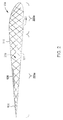
- Figure 2 illustrates a sectional view of a wing 114 of the aircraft 100 along section line 2-2, according to one aspect of the disclosure.
- the wing 114 includes an outer skin 215 defining the outward surface thereof.
- a three-dimensional, cross-linked wire truss structure 219 is positioned within the skin 215 to provide support to the skin 215 and to maintain the skin 215 in a predetermined shape.
- the three-dimensional, cross-linked wire truss structure 219 is a three-dimensional lattice structure formed by a plurality of cross-linked or intersecting wire segments of thermoplastic material. The wire segments of thermoplastic material are joined at respective intersections to form a unitary piece of material, thereby facilitating increased structural strength of the three-dimensional, cross-linked wire truss structure 219.
- the three-dimensional, cross-linked wire truss structure 219 defines an open lattice structure having a plurality of openings 221 (two are labeled).
- the plurality of openings 221 facilitate the use of soluble tooling in conjunction with the three-dimensional, cross-linked wire truss structure 219.
- a soluble material or medium may be used to support the segments of thermoplastic material while constructing the three-dimensional, cross-linked wire truss structure 219 such that the three-dimensional, cross-linked wire truss structure 219 has a desired shape or configuration.
- the three-dimensional, cross-linked wire truss structure 219 may be positioned in a desired orientation, and a soluble material may be applied to the three-dimensional, cross-linked wire truss structure 219 to maintain the configuration of the three-dimensional, cross-linked wire truss structure 219.
- the three-dimensional, cross-linked wire truss structure 219 may then be cured to maintain the desired orientation, and the soluble material may then be removed.
- a soluble material may be used to support the skins 215 relative to the three-dimensional, cross-linked wire truss structure 219 such that the skins 215 can be applied to the three-dimensional, cross-linked wire truss structure 219 and appropriate adhesion can occur therebetween.
- adhesion may occur via fusion bonding. The process of fusion-bonding involves heating and melting the thermoplastic material at the bond locations of the components and then pressing these surfaces together for solidification and consolidation. Subsequent to adhesion, the soluble material can be selectively dissolved with respect to the thermoplastic material into a solvent and removed, leaving only the three-dimensional, cross-linked wire truss structure 219 and the skins 215.
- the openings 221 of the three-dimensional, cross-linked wire truss structure 219 are sufficiently large enough to allow the solvent to dissolve and to remove the soluble material used in soluble tooling.
- the porosity of the three-dimensional, cross-linked wire truss structure 219 may be about 50 percent or greater to facilitate removal of the soluble material.
- the density of the three-dimensional, cross-linked wire truss structure 219 can be varied to reduce the weight of the three-dimensional, cross-linked wire truss structure 219 in relative areas of the wing 114.
- the trailing three-quarters 223a of the wing 114 has a truss structure density less than the leading quarter 223b of the wing 114, thus facilitating a desired weight balance of the wing 114.
- the leading quarter of the wing 114 may have a weight about equal to the trailing three-quarters of the wing.
- honeycomb structures generally have uniform densities, and thus, the only way to reduce the weight in the trailing edge of a wing when using the honeycomb structures is to completely remove portions of material. However, such removal may undesirably sacrifice structural rigidity and support, because material may be removed from key support areas within the wing 114.
- the three-dimensional, cross-linked wire truss structure 219 may utilize a varied density along the length of the wing 114, such that weight is reduced by using a less-dense support structure, but structural support remains in key locations because the three-dimensional, cross-linked wire truss structure 219 is not completely removed for weight reduction purposes.
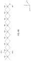
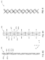
- Figures 3A-3C illustrate three-dimensional, cross-linked wire truss structures 319a-319c of varied densities, according to aspects of the disclosure.
- Figure 3A illustrates a three-dimensional, cross-linked wire truss structure 319a having a first density of thermoplastic segments 331 a.
- the relative angle 332 of intersection between segments 331 a, as well as the relative angle 333 of change of direction of each segment 331 a can be adjusted to facilitate a desired level of density of the three-dimensional, cross-linked wire truss structure 319a.
- Figure 3B illustrates a three-dimensional, cross-linked wire truss structure 319b having a second density of thermoplastic segments 331 b.
- the segments 331 b have varying or graded densities along a length thereof.
- the segments 331 b have a lower density in a region 334 and a greater density in a region 335.
- the density is adjusted by varying the angles 332, 333 along the length of the truss structure 319b.
- the density of the three-dimensional, cross-linked wire truss structure 319b can be varied along a length thereof (e.g., along the chord line) to produce the desired weight and support profile of the three-dimensional, cross-linked wire truss structure 319b.
- Figure 3C illustrates a three-dimensional, cross-linked wire truss structure 319c having overlapping or intertwined truss structures 335a, 335b.
- the three-dimensional, cross-linked wire truss structure 319c is formed from two separate truss structures 335a, 335b that may be simultaneously formed together, or may be subsequently formed relative to one another.
- a truss structure 335a may be formed and positioned into a desired configuration, and then subsequently, a truss structure 335b may be formed about the truss structure 335a.
- the truss structure 335a extends all or most of the length of the chord, such as a wing chord, while the second truss structure 335b extends a partial distance of the chord, for example, about 30 percent to about 50 percent of the length of the chord. It is contemplated, however, that the second truss structure 335b may extend a greater or lesser length of the chord than is illustrated, such as about 10 percent to about 90 percent of the chord, for example, and, specifically, about 30 percent to about 70 percent of the length of the chord, for example.
- truss structure 335a, 335b facilitates a more tailored approach to adjusting the relative weight and structural support of the three-dimensional, cross-linked wire truss structure 319c.
- a second truss structure such as the truss structure 335b, can be used to shift weight to the forward quarter of the chord of a wing, or to provide increased structural support in areas of the wing that bear a greater percentage of a load.
- honeycomb structures are not capable of such interlocking geometries, and thus, are more limited in shape and configurations.
- Figures 4A-4L illustrate formation of a three-dimensional, cross-linked wire truss structure, according to one aspect of the disclosure.
- Figure 4A illustrates positioning of a first segment 431a of thermoplastic material.
- the first wire segment 431 a is positioned on a supporting structure (not shown) in a saw tooth or zigzag pattern, as shown.
- the relative height of each zigzag, as well as the apexes of each zigzag per unit length, may be selected based on the desired structural needs and weight characteristics required by the finished support structure.
- the first wire segment 431 a may be dispensed from a roll of thermoplastic material using an automated placement device to position the first wire segment 431 in a desired zigzag configuration.
- the first wire segment 431 a is placed by an automated placement device moving in a first direction (such as the positive y direction), as indicated by arrow 480, while sweeping back and forth in the z direction to form a zigzag pattern.
- a second wire segment 431 b of thermoplastic material is disposed in a saw tooth pattern over the first wire segment 431 a.
- the saw tooth pattern of the second wire segment 431 b is offset from the saw tooth pattern of the first wire segment 431 a to form a crisscross pattern partially or entirely along the length of the first segment 431 a and the second wire segment 431 b.
- an automated placement device deposits the second wire segment 431 b when traveling in a second direction opposite the first direction (e.g., along a return path), as shown by arrow 481.
- the second wire segment 431 b may have a length about equal to the first wire segment 431 a.
- the number of intersections per unit length between the second wire segment 431 b and the first wire segment 431a can be adjusted by changing the angles 332 and 333 (shown in Figure 3B ). Generally, more points of intersection in a given length of material provide more resistance to local buckling.
- one half of the "X" formed by the intersection of the first wire segment 431 a and the second wire segment 431 b is in tension, while the other half is in compression, due to the forces acting upon the first wire segment 431 a and the second wire segment 431 b while supporting a load.
- the bonding between the portion in tension and the portion in compression reduces buckling of the portion in compression.
- a greater density of intersections per unit length can be used to further reduce local buckling; however, this may increase the density, and thus the weight, of the resultant truss supporting structure.
- the second wire segment 431 b and the first wire segment 431 a may be joined at intersections 432 by heating the intersections 432 to a temperature sufficient to cause adhesion therebetween.
- a laser may be used to heat desired regions (e.g., the intersections of the second wire segment 431 b and the first wire segment 431 a) rather than the entire segments themselves, in order to facilitate bonding at desired locations.
- thermoplastic resin such as polyetherketoneketone (PEKK) or polyetheretherketone (PEEK) (although other thermoplastic resins are possible and contemplated)
- PEKK polyetherketoneketone
- PEEK polyetheretherketone
- the desired areas of the thermoplastic material may be heated to temperature within a range of about 550 degrees Fahrenheit to about 750 degrees Fahrenheit, such as about 600 degrees Fahrenheit to about 700 degrees Fahrenheit, to facilitate bonding of the first wire segment 431 a and the second wire segment 431 b. It is contemplated that pressure may be applied to the first wire segment 431 a and the second segment 431 b to facilitate adhesion (e.g., fusion-bonding).
- thermoplastic materials may be much more heat stable than epoxies and/or phenolics. For example, certain thermoplastic materials may be heat stable up to temperatures of about 600 degrees Fahrenheit, while certain epoxies may only be heat stable up to about 200 degrees Fahrenheit.
- a third wire segment 431c is disposed over and aligned with first wire segment 431 a, as shown in Figure 4C .
- the third wire segment 431 c may be positioned by an automated placement device traveling in the first direction, as indicated by arrow 480. Once the third wire segment 431 c is positioned, the third wire segment 431 c may be joined to the first wire segment 431 a, for example, by heating portions of the first wire segment 431 a and/or the third wire segment 431 c to cause adhesion therebetween.
- the upward apexes of the saw tooth structures of the first wire segment 431 a and the third wire segment 431 c are joined together, as indicated at points 433.
- a fourth wire segment 431 d is disposed over and aligned with the second wire segment 431 b, as shown in Figure 4D .
- the fourth wire segment 431 d may be deposited by an automated placement device traveling in the second direction, as indicated by arrow 481, and may be about the same length as the second wire segment 431 b.
- the fourth wire segment 431 d is joined to the third wire segment 431c at points 434.
- the fourth wire segment 431d may also be joined to the second wire segment 431 b at the overlapping lower apexes of the saw tooth shapes formed by second wire segment 431b and fourth wire segment 431 d, as indicated at points 435.
- a fifth wire segment 431e is disposed over and aligned with the first wire segment 431 a and the third wire segment 431 c.
- the fifth wire segment 431e may be deposited by an automated placement device traveling in the first direction, as indicated by arrow 480. After placement of the fifth wire segment 431 e, the fifth wire segment 431 e may be adhered to the third wire segment 431 c at the overlapping lower apexes of the third wire segment 431 c and the fifth wire segment 431e, as shown at points 436.
- the fifth wire segment 431e may be adhered to the third wire segment 431 c using a heat source such as a laser, similar as to that described above.
- a sixth wire segment 431f is disposed over and aligned with the second wire segment 431 b and the fourth wire segment 431 d in a saw tooth pattern, as illustrated in Figure 5F.
- the sixth wire segment 431f may be deposited by an automated placement device moving in the second direction, as indicated by arrow 481.
- the sixth wire segment 431f may have a length about equal to the length of the second wire segment 431 b and the fourth wire segment 431 d.
- the sixth wire segment 431f is adhered to the fourth wire segment 431 d at the upper apexes and the intersections thereof using a heat source, such as a laser described above.
- the areas of adhesion are indicated at points 437, 438.
- the points 437 are the intersections of the fifth wire segment 431e and the sixth wire segment 437f.
- the adhesion points 438 are the upper apexes of the sixth wire segment 431f and the underlying fourth wire segment 431 d.
- Additional segments may be disposed on the structure to generate a truss structure of desired dimensions. For example, additional depositions and adhesions, such as those shown in Figures 4C-4F , may be repeated as desired. Additionally, it is to be noted that the particular adhesion points described herein are only examples, and other areas of adhesion between segments are contemplated.
- Figure 4G illustrates a rotated view of the segments 431a-431f in stacked configuration. Voids or spacing are illustrated between the wire segments 431a-431f for clarity.
- the segments 431a-431f are shown in partially expanded configurations, respectively.
- Figure 4H illustrates a top view of the three-dimensional, cross-linked wire truss structure 419
- Figure 4I illustrates a corresponding perspective view of the three-dimensional, cross-linked wire truss structure 419.
- the wire segments 431a-431f are expanded in the x direction to form a three-dimensional structure, e.g., a three-dimensional, cross-linked wire truss structure 419. It is contemplated that the level of expansion may be adjusted to produce a desired density or configuration of the three-dimensional, cross-linked wire truss structure 419.
- Figures 4J and 4K illustrate the three-dimensional, cross-linked wire truss structure 419 in a further-yet expanded configuration.
- Figure 4J illustrates a top view of the three-dimensional, cross-linked wire truss structure 419
- Figure 4K illustrates a corresponding perspective view of the three-dimensional, cross-linked wire truss structure 419.
- the three-dimensional, cross-linked wire truss structure 419 may be subjected to thermal processing, such as an annealing operation, to maintain the three-dimensional, cross-linked wire truss structure 419 in a desired configuration.
- the resultant, expanded, three-dimensional configuration in a hardened state is illustrated in figure 4L .
- the structure in Figure 4L may be shaped, for example, into a wing, a rotor blade, or another component, by trimming the three-dimensional, cross-linked wire truss structure 419 to a desired shape and/or size.
- the wire segments 431a-431f may be expanded to a desired distance such that the saw tooth structures of each wire segment 431a-431f are oriented in desired directions, thus facilitating directional load transfer when a load is applied.
- Directional load transfer allows an increased structural load to be applied while using a relatively reduced amount of supporting material, thus reducing the weight of the three-dimensional, cross-linked wire truss structure 419.
- honeycomb support structures which are formed from paper strips in combination with epoxies or glue strips
- honeycomb support structures are not adapted to support loads in particular directions, which may require more honeycomb material to be used to support a given load when compared to the three-dimensional, cross-linked wire truss structure 419.
- thermoplastic skins such as the skin 215 shown in Figure 2
- thermoplastic skins may be lighter than comparable skins formed form other materials, such as aluminum.
- thermoplastic skins are desirable, they have bonding issues with previously used support structure materials, such as honeycomb support structures, due to the bonding incompatibility between materials.
- thermoplastic support trusses can easily be bonded to thermoplastic skins.
- Thermoplastic skins may include, for example, wing skins or rotor blade skins formed from PEEK and/or PEKK.
- thermoplastic skins may allow a thermal process, used to maintain rigidity or configuration of the three-dimensional, cross-linked wire truss structure 419, to be omitted.
- the wire segments 431a-431f may be expanded into the desired configuration, and then a soluble material used in soluble tooling, may be applied to the expanded structure, and allowed to set, to maintain the wire segments 431a-431f in the expanded configuration.
- soluble material include soluble ceramics available from Advanced Ceramics Manufacturing of Arlington, Arizona. It is contemplated that metallic materials having melting points below that of the thermoplastic material may also be used.
- Thermoplastic skins may then be applied over the shape, and heated to form bonds between the thermoplastic skin and the three-dimensional, cross-linked wire truss structure 419.
- the soluble material may then be removed, leaving the three-dimensional, cross-linked wire truss structure 419 in a desired configuration due to the adhesive bonds between the three-dimensional, cross-linked wire truss structure 419 and the thermoplastic skin. Because extraneous adhesives are not utilized, the weight of the final structure is further reduced compared to previous structures.
- thermoplastic materials such as PEEK and PEKK
- fiber-impregnated thermoplastic materials may also be used.
- carbon-fiber-impregnated thermoplastic materials or glass-fiber-impregnated thermoplastic materials may be utilized; however, the use of other fibers is also contemplated.
- the utilization of impregnating fibers increases the strength of thermoplastic resin, thereby allowing less thermoplastic resin to be used to support the same load, and thus, facilitates the production of a lighter weight truss support structure.
- a plastic segment such as the wire segments 431a-431f
- the wire segments 431a-431f may have a diameter within a range of about 0.001 inches to about 0.25 inches. It is contemplated that the wire segments 431a-431f may have round cross sections or other cross sections. Additionally, the wire segments 431 a-431f may hollow wire, which may improve buckling strength.
- truss structures described herein may advantageously be used as support structures for other components, including those outside of aircraft components. Additionally, the truss structures described herein may be used in fluid containing vessels, such as fuel tanks, due to the open nature of the truss structures which allow fluids to flow therethrough. Moreover, while embodiments herein are described with respect to saw tooth patterns, it is contemplated that other oscillating or repeating patterns, such as sinusoidal patterns, may also be used. Additionally, embodiments herein utilize automated placement devices to position thermoplastic wires, however, it is contemplated that thermoplastic wires may also be positioned manually.
- Benefits of the disclosure include open support structures having reduced weight and directional load-bearing abilities.
- the support structures may easily be bonded to thermoplastic skins, or may also be easily bonded to one another to generate larger support structures, due to material compatibility.
- the bonds are fusion bonds.
- thermoplastic wire segments each include fibers impregnated therein.
- the fibers are carbon fiber.
- thermoplastic wire segments have a diameter within a range of about 0.0010 inches to about 0.0020 inches.
- thermoplastic wire segments comprise polyetherketoneketone.
- thermoplastic wire segments comprise polyetheretherketone.
- thermoplastic wire segments are formed from hollow wire.
- support structure further comprises a skin disposed on and bonded to the three-dimensional, cross-linked wire truss structure.
- the skin is bonded to the three-dimensional, cross-linked wire truss structure by a fusion-bonding.
- thermoplastic wire segments have a diameter within a range of 0.0010 inches to about 0.0020 inches.
- the density of the plurality of wire segments varies along a length of the support structure.
- the method further comprises expanding the first wire segment, the second wire segment, and the third wire segment.
- the method further comprises disposing a fourth wire segment over the third wire segment, the fourth wire segment having the second saw tooth pattern, the fourth wire segment aligned with the second wire segment.
- the method further comprises adhering the fourth wire segment to the second wire segment and the third wire segment.
- the method further comprises disposing fifth wire segment over the fourth wire segment, the fifth wire segment having the first saw tooth pattern and aligned with the first wire segment and the third wire segment.
- the method further comprises adhering the fifth wire segment to the third wire segment.
- adhering the second wire segment to the first wire segment comprises fusion bonding the second wire segment to the first wire segment.
- the method further comprises heat treating the first wire segment, the second wire segment, and the third wire segment after expanding the first wire segment, the second wire segment, and the third wire segment.
- the method further comprises adhering a thermoplastic skin to the first wire segment, the second wire segment, and the third wire segment.
- the method further comprises maintaining the first wire segment, the second wire segment, and the third wire segment in an expanded configuration using a soluble tooling medium.
Landscapes
- Engineering & Computer Science (AREA)
- Mechanical Engineering (AREA)
- Aviation & Aerospace Engineering (AREA)
- Architecture (AREA)
- Civil Engineering (AREA)
- Structural Engineering (AREA)
- Laminated Bodies (AREA)
- Moulding By Coating Moulds (AREA)
Abstract
Description
- Embodiments of the present disclosure generally relate to a lightweight thermoplastic/fiber structure for transmitting shear and maintaining the shape of fairings for wings and rotor blade structures.
- To maintain stability, torsionally soft structures such as long, slender wings and rotor blades should have a center of gravity in the forward quarter of the blade chord. Fairings are typically formed from skins and a core 'sandwich' structure. Composite materials that use thermoplastic, melt-bondable resins provide the possibility of more easily manufactured and tougher structures. Back pressure is needed when forming thermoplastic skins to create a high quality surface and to provide good adhesion of parts of assemblies.
- Existing solutions utilize ribs, honeycomb structures, or foam as the core material for fairing structures. Honeycomb structures are often used in rotor blades, however, honeycomb is difficult to melt bond to thermoplastic skins as it does not provide sufficient back pressure over the open portion of the honeycomb cells. Honeycomb structures also pose problems when using soluble tooling. In particular, honeycomb structures do not provide a sufficiently open structure to wash out the soluble tooling medium, even when using a breathable honeycomb structure. Ribs may also be used to form fairing structures. However, ribs must be spaced sufficiently far apart so as not to add too much additional weight. The increased spacing between ribs requires additional stiffening components and thicker skins, which add undesirable weight.
- The present disclosure generally relates to thermoplastic truss structures and methods of forming the same. The truss structures are formed using thermoplastic materials, such as fiber reinforced thermoplastic resins, and facilitate directional load support based on the shape of the truss structure. In one example, multiple two-dimensional patterns of fiber reinforced thermoplastic resin are disposed on one another in a saw tooth pattern, sinusoidal pattern, or other repeating pattern, and adhered to one another in selective locations. The two dimensional patterns may then be expanded in a third dimension to form a three-dimensional, cross-linked truss structure. The three-dimensional, cross-linked truss structure may then be heated or otherwise treated to maintain the three-dimensional shape.
- In one embodiment, a support structure comprises a three-dimensional, cross-linked truss structure comprising a plurality of thermoplastic wire segments bonded together. The three-dimensional, cross-linked truss structure may be used as a support structure for wings, rotor blades, fuel tanks, and other mechanical components.
- In another embodiment, a method of forming a support structure comprises positioning a first wire segment of thermoplastic material, the first wire segment having a first saw tooth pattern; positioning a second wire segment of thermoplastic material over the first wire segment, the second segment wire segment having a second saw tooth pattern offset from the first saw tooth pattern; adhering the second wire segment to the first wire segment; positioning a third wire segment of thermoplastic material over the second wire segment, the third wire segment having the first saw tooth pattern, the third wire segment aligned with the first wire segment and offset from the second wire segment; adhering the third wire segment to the first wire segment; and expanding the first wire segment, the second wire segment, and the third wire segment.
- So that the manner in which the above recited features of the present disclosure can be understood in detail, a more particular description of the disclosure, briefly summarized above, may be had by reference to embodiments, some of which are illustrated in the appended drawings. It is to be noted, however, that the appended drawings illustrate only exemplary embodiments and are therefore not to be considered limiting of their scope, and the disclosure may admit to other equally effective embodiments.
-
Figure 1 schematically represents an aircraft, according to one aspect of the disclosure. -
Figure 2 is a diagrammatic representation of a sectional view of a wing of an aircraft, according to one aspect of the disclosure. -
Figures 3A-3C are diagrammatic representations of truss structures of varied densities, according to aspects of the disclosure. -
Figures 4A-4L are diagrammatic representations illustrating formation of a truss structure, according to one aspect of the disclosure. - To facilitate understanding, identical reference numerals have been used, where possible, to designate identical elements that are common to the figures. It is contemplated that elements and features of one embodiment may be beneficially incorporated in other embodiments without further recitation.
- The present disclosure generally relates to thermoplastic truss structures and methods of forming the same. The truss structures are formed using thermoplastic materials, such as fiber reinforced thermoplastic resins, and facilitate directional load support based on the shape of the truss structure. In one example, multiple two-dimensional patterns of fiber reinforced thermoplastic resin are disposed on one another in a saw tooth pattern and adhered to one another in selective locations. The two dimensional patterns may then be expanded in a third dimension to form a three-dimensional, cross-linked truss structure. The three-dimensional, cross-linked truss structure may then be heated or otherwise treated to maintain the three-dimensional shape. The three-dimensional, cross-linked truss structure may be used as a support structure for wings, rotor blades, fuel tanks, and other mechanical components.
-
Figure 1 schematically represents anaircraft 100 according to one aspect of the disclosure. Theaircraft 100 illustrated inFigure 1 includesfuselage 110 for holding passengers and/or cargo. Twowings 114, which provide the lift needed to fly theaircraft 100, are coupled to opposite sides of thefuselage 110. Avertical stabilizer 116 and twohorizontal stabilizers 118 are coupled to thefuselage 110 at a trailing end thereof. One or more engines 102 (two are shown), which provide the thrust needed to propel theaircraft 100 forward, are coupled to thewings 114. - Also present on the
wings 114 ofaircraft 100 arespoilers 128,flaps 126, andslats 130, which may be referred to as secondary flight control surfaces.Spoilers 128 are located on thewings 114 and perform a variety of functions, including assisting in the control of vertical flight path, acting as air brakes to control the forward speed of theaircraft 100, and acting as ground spoilers to reduce wing lift to help maintain contact between the landing gear and the runway when braking. Theflaps 126 and theslats 130 are located on the wings of theaircraft 100 to change the lift and drag forces affecting theaircraft 100, with theflaps 126 positioned at the trailing edge ofwing 114 and theslats 130 positioned at the leading edge of thewing 114. When theflaps 126 and theslats 130 are extended, the shape of thewing 114 changes to provide more lift. With an increased lift, theaircraft 100 is able to fly at lower speeds, thus simplifying both the landing procedure and the take-off procedure. - The
aircraft 100 also includes primary flight controls to facilitate directional changes of theaircraft 100 during flight. The primary flight control surfaces on theaircraft 100 includeailerons 124,elevators 120, and arudder 122. Theailerons 124 are located on the trailing edges of thewings 114 of theaircraft 100 and control the roll of theaircraft 100. Theelevators 120 are located on thehorizontal stabilizer 118 of theaircraft 100 and control the pitch of theaircraft 100. Therudder 122 is located on thevertical stabilizer 116 and controls the yaw of theaircraft 100. In some aircrafts, there may be cables or wires (not shown) connecting pilot controls to actuators used to move the primary control surfaces. -
Figure 2 illustrates a sectional view of awing 114 of theaircraft 100 along section line 2-2, according to one aspect of the disclosure. Thewing 114 includes anouter skin 215 defining the outward surface thereof. A three-dimensional, cross-linkedwire truss structure 219 is positioned within theskin 215 to provide support to theskin 215 and to maintain theskin 215 in a predetermined shape. The three-dimensional, cross-linkedwire truss structure 219 is a three-dimensional lattice structure formed by a plurality of cross-linked or intersecting wire segments of thermoplastic material. The wire segments of thermoplastic material are joined at respective intersections to form a unitary piece of material, thereby facilitating increased structural strength of the three-dimensional, cross-linkedwire truss structure 219. - The three-dimensional, cross-linked
wire truss structure 219 defines an open lattice structure having a plurality of openings 221 (two are labeled). The plurality ofopenings 221 facilitate the use of soluble tooling in conjunction with the three-dimensional, cross-linkedwire truss structure 219. In one example, a soluble material or medium (not shown) may be used to support the segments of thermoplastic material while constructing the three-dimensional, cross-linkedwire truss structure 219 such that the three-dimensional, cross-linkedwire truss structure 219 has a desired shape or configuration. In such an example, the three-dimensional, cross-linkedwire truss structure 219 may be positioned in a desired orientation, and a soluble material may be applied to the three-dimensional, cross-linkedwire truss structure 219 to maintain the configuration of the three-dimensional, cross-linkedwire truss structure 219. The three-dimensional, cross-linkedwire truss structure 219 may then be cured to maintain the desired orientation, and the soluble material may then be removed. - Alternatively, a soluble material may be used to support the
skins 215 relative to the three-dimensional, cross-linkedwire truss structure 219 such that theskins 215 can be applied to the three-dimensional, cross-linkedwire truss structure 219 and appropriate adhesion can occur therebetween. In one example, adhesion may occur via fusion bonding. The process of fusion-bonding involves heating and melting the thermoplastic material at the bond locations of the components and then pressing these surfaces together for solidification and consolidation. Subsequent to adhesion, the soluble material can be selectively dissolved with respect to the thermoplastic material into a solvent and removed, leaving only the three-dimensional, cross-linkedwire truss structure 219 and theskins 215. Unlike previously-used honeycomb structures, theopenings 221 of the three-dimensional, cross-linkedwire truss structure 219 are sufficiently large enough to allow the solvent to dissolve and to remove the soluble material used in soluble tooling. In one example, the porosity of the three-dimensional, cross-linkedwire truss structure 219 may be about 50 percent or greater to facilitate removal of the soluble material. - Additionally, in further contrast to honeycomb structures, the density of the three-dimensional, cross-linked wire truss structure 219 (e.g., number of wire segment intersections per unit length) can be varied to reduce the weight of the three-dimensional, cross-linked
wire truss structure 219 in relative areas of thewing 114. For example, the trailing three-quarters 223a of thewing 114 has a truss structure density less than theleading quarter 223b of thewing 114, thus facilitating a desired weight balance of thewing 114. In one example, the leading quarter of thewing 114 may have a weight about equal to the trailing three-quarters of the wing. It is desirable to shift the weight towards the leading edge of the chord to reduce the likelihood of flutter. In contrast, honeycomb structures generally have uniform densities, and thus, the only way to reduce the weight in the trailing edge of a wing when using the honeycomb structures is to completely remove portions of material. However, such removal may undesirably sacrifice structural rigidity and support, because material may be removed from key support areas within thewing 114. In contrast, the three-dimensional, cross-linkedwire truss structure 219 may utilize a varied density along the length of thewing 114, such that weight is reduced by using a less-dense support structure, but structural support remains in key locations because the three-dimensional, cross-linkedwire truss structure 219 is not completely removed for weight reduction purposes. -
Figures 3A-3C illustrate three-dimensional, cross-linkedwire truss structures 319a-319c of varied densities, according to aspects of the disclosure.Figure 3A illustrates a three-dimensional, cross-linkedwire truss structure 319a having a first density ofthermoplastic segments 331 a. Therelative angle 332 of intersection betweensegments 331 a, as well as therelative angle 333 of change of direction of eachsegment 331 a can be adjusted to facilitate a desired level of density of the three-dimensional, cross-linkedwire truss structure 319a. -
Figure 3B illustrates a three-dimensional, cross-linkedwire truss structure 319b having a second density ofthermoplastic segments 331 b. In particular, thesegments 331 b have varying or graded densities along a length thereof. Thesegments 331 b have a lower density in aregion 334 and a greater density in aregion 335. The density is adjusted by varying theangles truss structure 319b. Thus, as illustrated, the density of the three-dimensional, cross-linkedwire truss structure 319b can be varied along a length thereof (e.g., along the chord line) to produce the desired weight and support profile of the three-dimensional, cross-linkedwire truss structure 319b. -
Figure 3C illustrates a three-dimensional, cross-linkedwire truss structure 319c having overlapping or intertwinedtruss structures wire truss structure 319c is formed from twoseparate truss structures truss structure 335a may be formed and positioned into a desired configuration, and then subsequently, atruss structure 335b may be formed about thetruss structure 335a. As illustrated, thetruss structure 335a extends all or most of the length of the chord, such as a wing chord, while thesecond truss structure 335b extends a partial distance of the chord, for example, about 30 percent to about 50 percent of the length of the chord. It is contemplated, however, that thesecond truss structure 335b may extend a greater or lesser length of the chord than is illustrated, such as about 10 percent to about 90 percent of the chord, for example, and, specifically, about 30 percent to about 70 percent of the length of the chord, for example. - The utilization of two
separate truss structures wire truss structure 319c. In particular, a second truss structure, such as thetruss structure 335b, can be used to shift weight to the forward quarter of the chord of a wing, or to provide increased structural support in areas of the wing that bear a greater percentage of a load. In contrast, honeycomb structures are not capable of such interlocking geometries, and thus, are more limited in shape and configurations. -
Figures 4A-4L illustrate formation of a three-dimensional, cross-linked wire truss structure, according to one aspect of the disclosure.Figure 4A illustrates positioning of afirst segment 431a of thermoplastic material. Thefirst wire segment 431 a is positioned on a supporting structure (not shown) in a saw tooth or zigzag pattern, as shown. The relative height of each zigzag, as well as the apexes of each zigzag per unit length, may be selected based on the desired structural needs and weight characteristics required by the finished support structure. - The
first wire segment 431 a may be dispensed from a roll of thermoplastic material using an automated placement device to position the first wire segment 431 in a desired zigzag configuration. In one example, thefirst wire segment 431 a is placed by an automated placement device moving in a first direction (such as the positive y direction), as indicated byarrow 480, while sweeping back and forth in the z direction to form a zigzag pattern. - Subsequently, as shown in
Figure 4B , asecond wire segment 431 b of thermoplastic material is disposed in a saw tooth pattern over thefirst wire segment 431 a. The saw tooth pattern of thesecond wire segment 431 b is offset from the saw tooth pattern of thefirst wire segment 431 a to form a crisscross pattern partially or entirely along the length of thefirst segment 431 a and thesecond wire segment 431 b. In one example, an automated placement device deposits thesecond wire segment 431 b when traveling in a second direction opposite the first direction (e.g., along a return path), as shown byarrow 481. Thesecond wire segment 431 b may have a length about equal to thefirst wire segment 431 a. - When positioning the
second wire segment 431 b, the number of intersections per unit length between thesecond wire segment 431 b and thefirst wire segment 431a can be adjusted by changing theangles 332 and 333 (shown inFigure 3B ). Generally, more points of intersection in a given length of material provide more resistance to local buckling. In any given cross section, one half of the "X" formed by the intersection of thefirst wire segment 431 a and thesecond wire segment 431 b is in tension, while the other half is in compression, due to the forces acting upon thefirst wire segment 431 a and thesecond wire segment 431 b while supporting a load. The bonding between the portion in tension and the portion in compression reduces buckling of the portion in compression. A greater density of intersections per unit length can be used to further reduce local buckling; however, this may increase the density, and thus the weight, of the resultant truss supporting structure. - After placement of the
second wire segment 431 b, thesecond wire segment 431 b and thefirst wire segment 431 a may be joined atintersections 432 by heating theintersections 432 to a temperature sufficient to cause adhesion therebetween. In one example, a laser may be used to heat desired regions (e.g., the intersections of thesecond wire segment 431 b and thefirst wire segment 431 a) rather than the entire segments themselves, in order to facilitate bonding at desired locations. - When using a thermoplastic resin, such as polyetherketoneketone (PEKK) or polyetheretherketone (PEEK) (although other thermoplastic resins are possible and contemplated), the desired areas of the thermoplastic material may be heated to temperature within a range of about 550 degrees Fahrenheit to about 750 degrees Fahrenheit, such as about 600 degrees Fahrenheit to about 700 degrees Fahrenheit, to facilitate bonding of the
first wire segment 431 a and thesecond wire segment 431 b. It is contemplated that pressure may be applied to thefirst wire segment 431 a and thesecond segment 431 b to facilitate adhesion (e.g., fusion-bonding). - After heating, the
first wire segment 431 a and thesecond wire segment 431 b may be allowed to cool to facilitate setting of the bond. In contrast to epoxy materials, such as those used in honeycomb structures, bond formation using thermoplastic materials is much quicker. For example, bonds between thermoplastics may be formed and set in seconds or minutes, while bonds using epoxies require hours to set. Thus, utilization of thermoplastic materials, as disclosed herein, may facilitate reduced construction times compared to support structures using epoxies. Additionally, thermoplastic materials may be much more heat stable than epoxies and/or phenolics. For example, certain thermoplastic materials may be heat stable up to temperatures of about 600 degrees Fahrenheit, while certain epoxies may only be heat stable up to about 200 degrees Fahrenheit. - After bonding the
second wire segment 431 b and thefirst wire segment 431a, athird wire segment 431c is disposed over and aligned withfirst wire segment 431 a, as shown inFigure 4C . Thethird wire segment 431 c may be positioned by an automated placement device traveling in the first direction, as indicated byarrow 480. Once thethird wire segment 431 c is positioned, thethird wire segment 431 c may be joined to thefirst wire segment 431 a, for example, by heating portions of thefirst wire segment 431 a and/or thethird wire segment 431 c to cause adhesion therebetween. As shown inFigure 4C , the upward apexes of the saw tooth structures of thefirst wire segment 431 a and thethird wire segment 431 c are joined together, as indicated atpoints 433. - After deposition and adhesion of the
third wire segment 431 c, afourth wire segment 431 d is disposed over and aligned with thesecond wire segment 431 b, as shown inFigure 4D . Thefourth wire segment 431 d may be deposited by an automated placement device traveling in the second direction, as indicated byarrow 481, and may be about the same length as thesecond wire segment 431 b. Thefourth wire segment 431 d is joined to thethird wire segment 431c atpoints 434. Thefourth wire segment 431d may also be joined to thesecond wire segment 431 b at the overlapping lower apexes of the saw tooth shapes formed bysecond wire segment 431b andfourth wire segment 431 d, as indicated atpoints 435. - As illustrated in
Figure 4E , afifth wire segment 431e is disposed over and aligned with thefirst wire segment 431 a and thethird wire segment 431 c. Thefifth wire segment 431e may be deposited by an automated placement device traveling in the first direction, as indicated byarrow 480. After placement of thefifth wire segment 431 e, thefifth wire segment 431 e may be adhered to thethird wire segment 431 c at the overlapping lower apexes of thethird wire segment 431 c and thefifth wire segment 431e, as shown at points 436. Thefifth wire segment 431e may be adhered to thethird wire segment 431 c using a heat source such as a laser, similar as to that described above. - After placement of the
fifth wire segment 431e, asixth wire segment 431f is disposed over and aligned with thesecond wire segment 431 b and thefourth wire segment 431 d in a saw tooth pattern, as illustrated in Figure 5F. Thesixth wire segment 431f may be deposited by an automated placement device moving in the second direction, as indicated byarrow 481. Thesixth wire segment 431f may have a length about equal to the length of thesecond wire segment 431 b and thefourth wire segment 431 d. Thesixth wire segment 431f is adhered to thefourth wire segment 431 d at the upper apexes and the intersections thereof using a heat source, such as a laser described above. The areas of adhesion are indicated atpoints points 437 are the intersections of thefifth wire segment 431e and the sixth wire segment 437f. The adhesion points 438 are the upper apexes of thesixth wire segment 431f and the underlyingfourth wire segment 431 d. - Additional segments may be disposed on the structure to generate a truss structure of desired dimensions. For example, additional depositions and adhesions, such as those shown in
Figures 4C-4F , may be repeated as desired. Additionally, it is to be noted that the particular adhesion points described herein are only examples, and other areas of adhesion between segments are contemplated. -
Figure 4G illustrates a rotated view of thesegments 431a-431f in stacked configuration. Voids or spacing are illustrated between thewire segments 431a-431f for clarity. InFigure 4H and Figure 4I , thesegments 431a-431f are shown in partially expanded configurations, respectively.Figure 4H illustrates a top view of the three-dimensional, cross-linkedwire truss structure 419, andFigure 4I illustrates a corresponding perspective view of the three-dimensional, cross-linkedwire truss structure 419. With reference toFigures 4G and 4H , thewire segments 431a-431f are expanded in the x direction to form a three-dimensional structure, e.g., a three-dimensional, cross-linkedwire truss structure 419. It is contemplated that the level of expansion may be adjusted to produce a desired density or configuration of the three-dimensional, cross-linkedwire truss structure 419. -
Figures 4J and 4K illustrate the three-dimensional, cross-linkedwire truss structure 419 in a further-yet expanded configuration.Figure 4J illustrates a top view of the three-dimensional, cross-linkedwire truss structure 419, andFigure 4K illustrates a corresponding perspective view of the three-dimensional, cross-linkedwire truss structure 419. With thetruss structure 419 expanded into a desired configuration, the three-dimensional, cross-linkedwire truss structure 419 may be subjected to thermal processing, such as an annealing operation, to maintain the three-dimensional, cross-linkedwire truss structure 419 in a desired configuration. The resultant, expanded, three-dimensional configuration in a hardened state is illustrated infigure 4L . The structure inFigure 4L may be shaped, for example, into a wing, a rotor blade, or another component, by trimming the three-dimensional, cross-linkedwire truss structure 419 to a desired shape and/or size. - The
wire segments 431a-431f may be expanded to a desired distance such that the saw tooth structures of eachwire segment 431a-431f are oriented in desired directions, thus facilitating directional load transfer when a load is applied. Directional load transfer allows an increased structural load to be applied while using a relatively reduced amount of supporting material, thus reducing the weight of the three-dimensional, cross-linkedwire truss structure 419. In contrast, honeycomb support structures (which are formed from paper strips in combination with epoxies or glue strips) are not adapted to support loads in particular directions, which may require more honeycomb material to be used to support a given load when compared to the three-dimensional, cross-linkedwire truss structure 419. - The three-dimensional, cross-linked
wire truss structure 419 also facilitates the use of thermoplastic skins (such as theskin 215 shown inFigure 2 ), which may be lighter than comparable skins formed form other materials, such as aluminum. While thermoplastic skins are desirable, they have bonding issues with previously used support structure materials, such as honeycomb support structures, due to the bonding incompatibility between materials. However, due to the likeness in materials, thermoplastic support trusses can easily be bonded to thermoplastic skins. Thermoplastic skins may include, for example, wing skins or rotor blade skins formed from PEEK and/or PEKK. - In one example, the use of thermoplastic skins may allow a thermal process, used to maintain rigidity or configuration of the three-dimensional, cross-linked
wire truss structure 419, to be omitted. In such an example, thewire segments 431a-431f may be expanded into the desired configuration, and then a soluble material used in soluble tooling, may be applied to the expanded structure, and allowed to set, to maintain thewire segments 431a-431f in the expanded configuration. Examples of soluble material include soluble ceramics available from Advanced Ceramics Manufacturing of Tucson, Arizona. It is contemplated that metallic materials having melting points below that of the thermoplastic material may also be used. - Thermoplastic skins may then be applied over the shape, and heated to form bonds between the thermoplastic skin and the three-dimensional, cross-linked
wire truss structure 419. The soluble material may then be removed, leaving the three-dimensional, cross-linkedwire truss structure 419 in a desired configuration due to the adhesive bonds between the three-dimensional, cross-linkedwire truss structure 419 and the thermoplastic skin. Because extraneous adhesives are not utilized, the weight of the final structure is further reduced compared to previous structures. - While embodiments herein refer to the use of thermoplastic materials, such as PEEK and PEKK, it is contemplated that fiber-impregnated thermoplastic materials may also be used. In one example, carbon-fiber-impregnated thermoplastic materials or glass-fiber-impregnated thermoplastic materials may be utilized; however, the use of other fibers is also contemplated. The utilization of impregnating fibers increases the strength of thermoplastic resin, thereby allowing less thermoplastic resin to be used to support the same load, and thus, facilitates the production of a lighter weight truss support structure.
- In one embodiment, a plastic segment, such as the
wire segments 431a-431f, may have a diameter of about 0.0020 inches to about 0.0030 inches when non-impregnated, and may have diameter less than about 0.0020 inches, such as 0.0010 inches to about 0.0020 inches, when impregnated with fiber. In another example, thewire segments 431a-431f may have a diameter within a range of about 0.001 inches to about 0.25 inches. It is contemplated that thewire segments 431a-431f may have round cross sections or other cross sections. Additionally, the wire segments 431 a-431f may hollow wire, which may improve buckling strength. - While embodiments herein are described with respect to aircraft wings and rotor blades, it is noted that the truss structures described herein may advantageously be used as support structures for other components, including those outside of aircraft components. Additionally, the truss structures described herein may be used in fluid containing vessels, such as fuel tanks, due to the open nature of the truss structures which allow fluids to flow therethrough. Moreover, while embodiments herein are described with respect to saw tooth patterns, it is contemplated that other oscillating or repeating patterns, such as sinusoidal patterns, may also be used. Additionally, embodiments herein utilize automated placement devices to position thermoplastic wires, however, it is contemplated that thermoplastic wires may also be positioned manually.
- Benefits of the disclosure include open support structures having reduced weight and directional load-bearing abilities. The support structures may easily be bonded to thermoplastic skins, or may also be easily bonded to one another to generate larger support structures, due to material compatibility.
- Further, according to a first aspect of the disclosure, there is provided:
- A support structure, comprising:
- a three-dimensional, cross-linked wire truss structure comprising a plurality of thermoplastic wire segments bonded together.
- Optionally, the bonds are fusion bonds.
- Optionally, the thermoplastic wire segments each include fibers impregnated therein.
- Optionally, the fibers are carbon fiber.
- Optionally, the thermoplastic wire segments have a diameter within a range of about 0.0010 inches to about 0.0020 inches.
- Optionally, the thermoplastic wire segments comprise polyetherketoneketone.
- Optionally, the thermoplastic wire segments comprise polyetheretherketone.
- Optionally, the thermoplastic wire segments are formed from hollow wire.
- Optionally, support structure further comprises a skin disposed on and bonded to the three-dimensional, cross-linked wire truss structure.
- Optionally, the skin is bonded to the three-dimensional, cross-linked wire truss structure by a fusion-bonding.
- Optionally, the thermoplastic wire segments have a diameter within a range of 0.0010 inches to about 0.0020 inches.
- Optionally, the density of the plurality of wire segments varies along a length of the support structure.
- According to a further aspect of the disclosure, there is provided:
- A method of forming a support structure, comprising:
- positioning a first wire segment of thermoplastic material, the first wire segment having a first saw tooth pattern;
- positioning a second wire segment of thermoplastic material over the first wire segment, the second segment wire segment having a second saw tooth pattern offset from the first saw tooth pattern;
- adhering the second wire segment to the first wire segment;
- positioning a third wire segment of thermoplastic material over the second wire segment, the third wire segment having the first saw tooth pattern, the third wire segment aligned with the first wire segment and offset from the second wire segment; and
- adhering the third wire segment to the first wire segment.
- Optionally, the method further comprises expanding the first wire segment, the second wire segment, and the third wire segment.
- Optionally, the method further comprises disposing a fourth wire segment over the third wire segment, the fourth wire segment having the second saw tooth pattern, the fourth wire segment aligned with the second wire segment.
- Optionally, the method further comprises adhering the fourth wire segment to the second wire segment and the third wire segment.
- Optionally, the method further comprises disposing fifth wire segment over the fourth wire segment, the fifth wire segment having the first saw tooth pattern and aligned with the first wire segment and the third wire segment.
- Optionally, the method further comprises adhering the fifth wire segment to the third wire segment.
- Optionally, adhering the second wire segment to the first wire segment comprises fusion bonding the second wire segment to the first wire segment.
- Optionally, the method further comprises heat treating the first wire segment, the second wire segment, and the third wire segment after expanding the first wire segment, the second wire segment, and the third wire segment.
- Optionally, the method further comprises adhering a thermoplastic skin to the first wire segment, the second wire segment, and the third wire segment.
- Optionally, the method further comprises maintaining the first wire segment, the second wire segment, and the third wire segment in an expanded configuration using a soluble tooling medium.
- While the foregoing is directed to embodiments of the present disclosure, other and further embodiments of the disclosure may be devised without departing from the basic scope thereof, and the scope thereof is determined by the claims that follow.
Claims (15)
- A support structure, comprising:a three-dimensional, cross-linked wire truss structure (219) comprising a plurality of thermoplastic wire segments (431 a, 431 b) bonded together.
- The support structure of claim 1, wherein the bonds are fusion bonds.
- The support structure of claims 1 or 2, wherein the thermoplastic wire segments (431 a, 431 b) each include fibers impregnated therein.
- The support structure of claims 1, 2 or 3, wherein the thermoplastic wire segments (431 a, 431 b) are formed from hollow wire.
- The support structure of claims 1, 2, 3 or 4, further comprising a skin (215) disposed on and bonded to the three-dimensional, cross-linked wire truss structure (219).
- The support structure of claims 1, 2, 3, 4, or 5, wherein the density of the plurality of wire segments (431 a, 431 b) varies along a length of the support structure.
- A method of forming a support structure, comprising:positioning a first wire segment of thermoplastic material (431 a), the first wire segment having a first saw tooth pattern;positioning a second wire segment of thermoplastic material (431 b) over the first wire segment (431 a), the second segment wire segment (431 b) having a second saw tooth pattern offset from the first saw tooth pattern;adhering the second wire segment (431 b) to the first wire segment (431 a);positioning a third wire segment of thermoplastic material (431 c) over the second wire segment (431 b), the third wire segment (431 c) having the first saw tooth pattern, the third wire segment (431 c) aligned with the first wire segment (431 a) and offset from the second wire segment (431 b); andadhering the third wire segment (431 c) to the first wire segment (431 a).
- The method of claim 7, further comprising expanding the first wire segment (431 a), the second wire segment (431 b), and the third wire segment (431 c).
- The method of claims 7 or 8, further comprising disposing a fourth wire segment (431 d) over the third wire segment (431 c), the fourth wire segment (431 d) having the second saw tooth pattern, the fourth wire segment (431 d) aligned with the second wire segment (431 b).
- The method of claim 9, further comprising adhering the fourth wire segment (431 d) to the second wire segment (431 b) and the third wire segment (431 c).
- The method of claim 10, further comprising disposing fifth wire segment (431 e) over the fourth wire segment (431 d), the fifth wire segment (431 e) having the first saw tooth pattern and aligned with the first wire segment (431 a) and the third wire segment (431 c).
- The method of claim 11, further comprising adhering the fifth wire segment (431 e) to the third wire segment (431 c).
- The method of claims 7, 8, 9, 10, 11 or 12, wherein adhering the second wire segment (431 b) to the first wire segment (431 a) comprises fusion bonding the second wire segment (431 b) to the first wire segment (431 a).
- The method of claims 7, 8, 9, 10, 11, 12 or 13, further comprising adhering a thermoplastic skin (215) to the first wire segment (431 a), the second wire segment (431 b), and the third wire segment (431 c).
- The method of claims 7, 8, 9, 10, 11, 12, 13 or 14, further comprising maintaining the first wire segment (431 a), the second wire segment (431 b), and the third wire segment (431 c) in an expanded configuration using a soluble tooling medium.
Applications Claiming Priority (1)
| Application Number | Priority Date | Filing Date | Title |
|---|---|---|---|
| US14/635,272 US10358821B2 (en) | 2015-03-02 | 2015-03-02 | Thermoplastic truss structure for use in wing and rotor blade structures and methods for manufacture |
Publications (2)
| Publication Number | Publication Date |
|---|---|
| EP3064337A1 true EP3064337A1 (en) | 2016-09-07 |
| EP3064337B1 EP3064337B1 (en) | 2020-11-11 |
Family
ID=55435987
Family Applications (1)
| Application Number | Title | Priority Date | Filing Date |
|---|---|---|---|
| EP16155999.2A Not-in-force EP3064337B1 (en) | 2015-03-02 | 2016-02-16 | Thermoplastic truss structure for use in wing and rotor blade structures and methods for manufacture |
Country Status (5)
| Country | Link |
|---|---|
| US (2) | US10358821B2 (en) |
| EP (1) | EP3064337B1 (en) |
| JP (1) | JP6732471B2 (en) |
| CN (1) | CN105936335B (en) |
| ES (1) | ES2851337T3 (en) |
Families Citing this family (11)
| Publication number | Priority date | Publication date | Assignee | Title |
|---|---|---|---|---|
| US10618217B2 (en) | 2013-10-30 | 2020-04-14 | Branch Technology, Inc. | Cellular fabrication and apparatus for additive manufacturing |
| US10850826B2 (en) * | 2017-03-24 | 2020-12-01 | The Boeing Company | Aircraft wing space frame |
| JP6989321B2 (en) * | 2017-08-29 | 2022-01-05 | 三菱重工業株式会社 | Flying object |
| DE102017128497A1 (en) * | 2017-11-30 | 2019-06-06 | Airbus Operations Gmbh | Leading edge arrangement for a flow body of a vehicle |
| US11485468B2 (en) * | 2018-09-27 | 2022-11-01 | The Boeing Company | Thermoplastic multi-grid overmolded/co-consolidated aircraft fuselage structure |
| US12157572B2 (en) | 2021-08-31 | 2024-12-03 | The Boeing Company | Method of making a control surface |
| US11993388B2 (en) | 2021-09-02 | 2024-05-28 | Rohr, Inc. | Corrugated stiffening devices utilizing peaks and valleys and methods of manufacture |
| US12014712B2 (en) | 2021-09-02 | 2024-06-18 | Rohr, Inc. | Corrugated acoustic stiffening devices and methods |
| US11780179B2 (en) * | 2021-09-02 | 2023-10-10 | Rohr, Inc. | Thermoplastic composite panel with corrugated peaks and troughs stiffening systems and methods |
| US11987353B2 (en) * | 2022-04-19 | 2024-05-21 | The Boeing Company | Thermoplastic skin panels, torque box and method |
| US20240092481A1 (en) * | 2022-09-16 | 2024-03-21 | Hydronalix, Inc. | Ceramic propeller |
Citations (4)
| Publication number | Priority date | Publication date | Assignee | Title |
|---|---|---|---|---|
| GB836461A (en) * | 1957-07-15 | 1960-06-01 | Boulton And Paul Ltd | Improvements in and relating to wire netting |
| US3419456A (en) * | 1964-03-25 | 1968-12-31 | Union Carbide Corp | Molded fabric |
| US5342679A (en) * | 1988-12-19 | 1994-08-30 | Lockheed Missiles & Space Company, Inc. | Grid structures |
| US20140061974A1 (en) * | 2012-08-29 | 2014-03-06 | Kenneth Tyler | Method and apparatus for continuous composite three-dimensional printing |
Family Cites Families (44)
| Publication number | Priority date | Publication date | Assignee | Title |
|---|---|---|---|---|
| US4453367A (en) * | 1981-07-10 | 1984-06-12 | General Electric Company | Honeycomb core material and sandwich construction structural building materials incorporating same |
| US5028474A (en) * | 1989-07-25 | 1991-07-02 | Czaplicki Ronald M | Cellular core structure providing gridlike bearing surfaces on opposing parallel planes of the formed core |
| US5180619A (en) | 1989-12-04 | 1993-01-19 | Supracor Systems, Inc. | Perforated honeycomb |
| US5128192A (en) | 1990-02-02 | 1992-07-07 | Northrop Corporation | Braided preform process for thermoplastic honeycomb cores |
| US5328744A (en) * | 1990-10-09 | 1994-07-12 | E. I. Du Pont De Nemours And Company | Panel having a core with thermoplastic resin facings |
| US5700337A (en) * | 1996-03-01 | 1997-12-23 | Mcdonnell Douglas Corporation | Fabrication method for composite structure adapted for controlled structural deformation |
| US6003283A (en) | 1998-05-07 | 1999-12-21 | Hexcel Corporation | Vented flexible honeycomb |
| JP3753313B2 (en) | 1999-11-26 | 2006-03-08 | 三洋化成工業株式会社 | Honeycomb core material for sandwich structure and manufacturing method thereof |
| US20030215613A1 (en) * | 2001-07-10 | 2003-11-20 | Inteplast Group, Ltd. | Light weight board of improved mechanical strength and process for production thereof |
| US6918920B1 (en) * | 2001-11-01 | 2005-07-19 | Advanced Cardiovascular Systems, Inc. | Catheter having an improved distal tip |
| US20080051866A1 (en) * | 2003-02-26 | 2008-02-28 | Chao Chin Chen | Drug delivery devices and methods |
| DE112004002127B4 (en) * | 2003-11-07 | 2008-10-23 | Industry Foundation Of Chonnam National University | Three-dimensional wirewound cellular lightweight structure and manufacturing method thereof |
| US7914728B2 (en) | 2004-07-14 | 2011-03-29 | Ngk Insulators, Ltd. | Method for manufacturing porous honeycomb structure |
| US7589037B2 (en) * | 2005-01-13 | 2009-09-15 | Basofil Fibers, Llc | Slickened or siliconized flame resistant fiber blends |
| DE102006008728B3 (en) * | 2006-02-24 | 2007-07-19 | Airbus Deutschland Gmbh | Producing a three-dimensional framework useful for making structural components of aircraft comprises applying heat and force to a two-dimensional lattice of rods |
| US7382959B1 (en) | 2006-10-13 | 2008-06-03 | Hrl Laboratories, Llc | Optically oriented three-dimensional polymer microstructures |
| US9669593B2 (en) * | 2007-06-14 | 2017-06-06 | The Boeing Company | Light weight thermoplastic flex foam and hybrid duct system |
| US8431214B2 (en) * | 2007-07-31 | 2013-04-30 | The Boeing Company | Composite structure having reinforced core and method of making same |
| US8061477B2 (en) * | 2008-08-20 | 2011-11-22 | The Boeing Company | Acoustic management of fluid flow within a duct |
| GB0900494D0 (en) * | 2009-01-14 | 2009-02-11 | Airbus Uk Ltd | Aerofoil Structure |
| US8593342B2 (en) | 2009-03-11 | 2013-11-26 | CSR Technology Holdings Inc. | Utilizing SBAS signals to improve GNSS receiver performance |
| MX2012004101A (en) * | 2009-10-09 | 2012-08-31 | Volm Companies Inc | Open mesh material and bags made therefrom. |
| US8609219B2 (en) | 2010-12-15 | 2013-12-17 | The Boeing Company | Selectively coupled fibers in composites |
| US20130284004A1 (en) * | 2011-10-17 | 2013-10-31 | E I Du Pont De Nemours And Company | Composite material; a ballistic resistant article made from same and method of making the article |
| US20130095716A1 (en) * | 2011-10-17 | 2013-04-18 | E. I. Du Pont De Nemours And Company | Composite material; a ballistic resistant article made from same and method of making the article |
| ES2404946B1 (en) * | 2011-10-21 | 2014-09-02 | Airbus Operations S.L. | AIRCRAFT FUSELAGE RESISTANT TO IMPACT AND TOLERANT TO IMPROVED DAMAGE |
| US9539773B2 (en) * | 2011-12-06 | 2017-01-10 | Hrl Laboratories, Llc | Net-shape structure with micro-truss core |
| CN104136212A (en) * | 2012-02-20 | 2014-11-05 | 帝人芳纶有限公司 | Composite for producing of an antiballistic article |
| US20140113104A1 (en) * | 2012-02-23 | 2014-04-24 | E I Du Pont De Nemours And Company | Fiber-resin composite sheet and article comprising the same |
| US9017806B2 (en) * | 2012-03-23 | 2015-04-28 | Hrl Laboratories, Llc | High airflow micro-truss structural apparatus |
| US9435060B2 (en) * | 2012-05-01 | 2016-09-06 | University Of Maryland | Continuous wound composite truss structures |
| US9321241B2 (en) * | 2012-05-11 | 2016-04-26 | The Boeing Company | Ventilated aero-structures, aircraft and associated methods |
| DE102012210043A1 (en) * | 2012-06-14 | 2013-12-19 | Airbus Operations Gmbh | Method and device for producing a lightweight structure and lightweight structure |
| JP2016506314A (en) * | 2012-12-03 | 2016-03-03 | イー・アイ・デュポン・ドウ・ヌムール・アンド・カンパニーE.I.Du Pont De Nemours And Company | Composite sheet and dedicated cargo container containing it |
| JP2016513030A (en) * | 2013-02-05 | 2016-05-12 | イー・アイ・デュポン・ドウ・ヌムール・アンド・カンパニーE.I.Du Pont De Nemours And Company | Composite sheet and cargo container containing it |
| US9884436B2 (en) * | 2014-04-17 | 2018-02-06 | GM Global Technology Operations LLC | Method for making a curved sandwich structure using a reconfigurable UV source mounting element |
| US10105941B2 (en) * | 2014-04-25 | 2018-10-23 | GM Global Technology Operations LLC | Stiffening and/or strengthening a structural member using a pre-made microtruss insert |
| US9376074B2 (en) * | 2014-04-25 | 2016-06-28 | GM Global Technology Operations LLC | Architected automotive impact beam |
| US10457013B2 (en) * | 2014-05-27 | 2019-10-29 | Dupont Safety & Construction, Inc. | Composite sheet and cargo container comprising same |
| US9511540B2 (en) * | 2014-08-07 | 2016-12-06 | GM Global Technology Operations LLC | Process for securing a micro-truss structure to a panel |
| US20160039168A1 (en) * | 2014-08-07 | 2016-02-11 | GM Global Technology Operations LLC | Design and processes for making light, stiff and strong structures |
| DE102014011775B4 (en) * | 2014-08-09 | 2016-08-11 | Florian Tuczek | Folding structure, component connection, sandwich panel, as well as folding method and tool |
| US20160089817A1 (en) * | 2014-09-25 | 2016-03-31 | GM Global Technology Operations LLC | Method for fabricating a sandwich box impact beam |
| US9533642B2 (en) * | 2014-09-25 | 2017-01-03 | GM Global Technology Operations LLC | Hierarchical sandwich structures |
-
2015
- 2015-03-02 US US14/635,272 patent/US10358821B2/en not_active Expired - Fee Related
-
2016
- 2016-02-16 EP EP16155999.2A patent/EP3064337B1/en not_active Not-in-force
- 2016-02-16 ES ES16155999T patent/ES2851337T3/en active Active
- 2016-02-22 JP JP2016030584A patent/JP6732471B2/en not_active Expired - Fee Related
- 2016-03-02 CN CN201610118580.3A patent/CN105936335B/en not_active Expired - Fee Related
-
2019
- 2019-07-12 US US16/510,088 patent/US20190330848A1/en not_active Abandoned
Patent Citations (4)
| Publication number | Priority date | Publication date | Assignee | Title |
|---|---|---|---|---|
| GB836461A (en) * | 1957-07-15 | 1960-06-01 | Boulton And Paul Ltd | Improvements in and relating to wire netting |
| US3419456A (en) * | 1964-03-25 | 1968-12-31 | Union Carbide Corp | Molded fabric |
| US5342679A (en) * | 1988-12-19 | 1994-08-30 | Lockheed Missiles & Space Company, Inc. | Grid structures |
| US20140061974A1 (en) * | 2012-08-29 | 2014-03-06 | Kenneth Tyler | Method and apparatus for continuous composite three-dimensional printing |
Also Published As
| Publication number | Publication date |
|---|---|
| JP2017013772A (en) | 2017-01-19 |
| JP6732471B2 (en) | 2020-07-29 |
| CN105936335A (en) | 2016-09-14 |
| EP3064337B1 (en) | 2020-11-11 |
| US10358821B2 (en) | 2019-07-23 |
| CN105936335B (en) | 2021-05-28 |
| US20190330848A1 (en) | 2019-10-31 |
| ES2851337T3 (en) | 2021-09-06 |
| US20160257396A1 (en) | 2016-09-08 |
Similar Documents
| Publication | Publication Date | Title |
|---|---|---|
| US10358821B2 (en) | Thermoplastic truss structure for use in wing and rotor blade structures and methods for manufacture | |
| US6190484B1 (en) | Monolithic composite wing manufacturing process | |
| ES2771103T3 (en) | Efficient substructures | |
| CN109922945B (en) | composite vehicle body | |
| US8642168B2 (en) | Composite structure having reinforced core and method of making the same | |
| CN110039795A (en) | Method for manufacturing aerospace component | |
| EP3205575B1 (en) | Laminar flow panel | |
| EP3204292B1 (en) | Process for assembling aircraft control surfaces | |
| KR101942841B1 (en) | A method and a thermoplastic blade | |
| US8545211B2 (en) | Method for manufacturing and attachment of wing fairings | |
| US11628601B2 (en) | Mold tools with anisotropic thermal properties and aligned carbon-reinforced thermoplastic fibres | |
| US11738493B2 (en) | Method of manufacturing an assembly fixture and a composite product | |
| US10967966B2 (en) | Method of fabricating a rotor blade filler body, and a rotor blade filler body comprising at least one cellular assembly having closed cells | |
| US10633084B2 (en) | Geodesic composite structures | |
| RU2628416C1 (en) | Wing and fin panel or operation of air vehicle from layer composite materials | |
| US20170291406A1 (en) | Joining structural members using foam | |
| US11319052B2 (en) | Leading-edge arrangement for a flow body of a vehicle | |
| EP3599089B1 (en) | Core structures for composite panels, aircraft including the same, and related methods | |
| US20250387972A1 (en) | Additive manufacturing of architectured morphing structures |
Legal Events
| Date | Code | Title | Description |
|---|---|---|---|
| PUAI | Public reference made under article 153(3) epc to a published international application that has entered the european phase |
Free format text: ORIGINAL CODE: 0009012 |
|
| 17P | Request for examination filed |
Effective date: 20160216 |
|
| AK | Designated contracting states |
Kind code of ref document: A1 Designated state(s): AL AT BE BG CH CY CZ DE DK EE ES FI FR GB GR HR HU IE IS IT LI LT LU LV MC MK MT NL NO PL PT RO RS SE SI SK SM TR |
|
| AX | Request for extension of the european patent |
Extension state: BA ME |
|
| GRAP | Despatch of communication of intention to grant a patent |
Free format text: ORIGINAL CODE: EPIDOSNIGR1 |
|
| STAA | Information on the status of an ep patent application or granted ep patent |
Free format text: STATUS: GRANT OF PATENT IS INTENDED |
|
| RIC1 | Information provided on ipc code assigned before grant |
Ipc: B29C 65/02 20060101AFI20200514BHEP Ipc: B29C 65/78 20060101ALN20200514BHEP Ipc: B29L 28/00 20060101ALN20200514BHEP Ipc: B29D 99/00 20100101ALI20200514BHEP Ipc: B64C 3/00 20060101ALI20200514BHEP Ipc: B29L 31/08 20060101ALN20200514BHEP Ipc: B29C 65/00 20060101ALI20200514BHEP Ipc: B29C 65/16 20060101ALN20200514BHEP Ipc: B29L 31/30 20060101ALN20200514BHEP |
|
| RIC1 | Information provided on ipc code assigned before grant |
Ipc: B29D 99/00 20100101ALI20200520BHEP Ipc: B29C 65/16 20060101ALN20200520BHEP Ipc: B29L 28/00 20060101ALN20200520BHEP Ipc: B29L 31/08 20060101ALN20200520BHEP Ipc: B29L 31/30 20060101ALN20200520BHEP Ipc: B29C 65/78 20060101ALN20200520BHEP Ipc: B29C 65/02 20060101AFI20200520BHEP Ipc: B64C 3/00 20060101ALI20200520BHEP Ipc: B29C 65/00 20060101ALI20200520BHEP |
|
| INTG | Intention to grant announced |
Effective date: 20200603 |
|
| GRAJ | Information related to disapproval of communication of intention to grant by the applicant or resumption of examination proceedings by the epo deleted |
Free format text: ORIGINAL CODE: EPIDOSDIGR1 |
|
| STAA | Information on the status of an ep patent application or granted ep patent |
Free format text: STATUS: REQUEST FOR EXAMINATION WAS MADE |
|
| GRAR | Information related to intention to grant a patent recorded |
Free format text: ORIGINAL CODE: EPIDOSNIGR71 |
|
| GRAS | Grant fee paid |
Free format text: ORIGINAL CODE: EPIDOSNIGR3 |
|
| STAA | Information on the status of an ep patent application or granted ep patent |
Free format text: STATUS: GRANT OF PATENT IS INTENDED |
|
| GRAA | (expected) grant |
Free format text: ORIGINAL CODE: 0009210 |
|
| STAA | Information on the status of an ep patent application or granted ep patent |
Free format text: STATUS: THE PATENT HAS BEEN GRANTED |
|
| INTC | Intention to grant announced (deleted) | ||
| RIC1 | Information provided on ipc code assigned before grant |
Ipc: B29C 65/16 20060101ALN20200930BHEP Ipc: B29C 65/00 20060101ALI20200930BHEP Ipc: B29C 65/02 20060101AFI20200930BHEP Ipc: B29L 31/08 20060101ALN20200930BHEP Ipc: B29C 65/78 20060101ALN20200930BHEP Ipc: B64C 3/00 20060101ALI20200930BHEP Ipc: B29L 28/00 20060101ALN20200930BHEP Ipc: B29L 31/30 20060101ALN20200930BHEP Ipc: B29D 99/00 20100101ALI20200930BHEP |
|
| AK | Designated contracting states |
Kind code of ref document: B1 Designated state(s): AL AT BE BG CH CY CZ DE DK EE ES FI FR GB GR HR HU IE IS IT LI LT LU LV MC MK MT NL NO PL PT RO RS SE SI SK SM TR |
|
| INTG | Intention to grant announced |
Effective date: 20201006 |
|
| REG | Reference to a national code |
Ref country code: GB Ref legal event code: FG4D |
|
| REG | Reference to a national code |
Ref country code: CH Ref legal event code: EP |
|
| REG | Reference to a national code |
Ref country code: AT Ref legal event code: REF Ref document number: 1333039 Country of ref document: AT Kind code of ref document: T Effective date: 20201115 |
|
| REG | Reference to a national code |
Ref country code: DE Ref legal event code: R096 Ref document number: 602016047530 Country of ref document: DE |
|
| REG | Reference to a national code |
Ref country code: IE Ref legal event code: FG4D |
|
| REG | Reference to a national code |
Ref country code: NL Ref legal event code: MP Effective date: 20201111 |
|
| REG | Reference to a national code |
Ref country code: AT Ref legal event code: MK05 Ref document number: 1333039 Country of ref document: AT Kind code of ref document: T Effective date: 20201111 |
|
| PG25 | Lapsed in a contracting state [announced via postgrant information from national office to epo] |
Ref country code: FI Free format text: LAPSE BECAUSE OF FAILURE TO SUBMIT A TRANSLATION OF THE DESCRIPTION OR TO PAY THE FEE WITHIN THE PRESCRIBED TIME-LIMIT Effective date: 20201111 Ref country code: PT Free format text: LAPSE BECAUSE OF FAILURE TO SUBMIT A TRANSLATION OF THE DESCRIPTION OR TO PAY THE FEE WITHIN THE PRESCRIBED TIME-LIMIT Effective date: 20210311 Ref country code: RS Free format text: LAPSE BECAUSE OF FAILURE TO SUBMIT A TRANSLATION OF THE DESCRIPTION OR TO PAY THE FEE WITHIN THE PRESCRIBED TIME-LIMIT Effective date: 20201111 Ref country code: NO Free format text: LAPSE BECAUSE OF FAILURE TO SUBMIT A TRANSLATION OF THE DESCRIPTION OR TO PAY THE FEE WITHIN THE PRESCRIBED TIME-LIMIT Effective date: 20210211 Ref country code: GR Free format text: LAPSE BECAUSE OF FAILURE TO SUBMIT A TRANSLATION OF THE DESCRIPTION OR TO PAY THE FEE WITHIN THE PRESCRIBED TIME-LIMIT Effective date: 20210212 |
|
| PG25 | Lapsed in a contracting state [announced via postgrant information from national office to epo] |
Ref country code: BG Free format text: LAPSE BECAUSE OF FAILURE TO SUBMIT A TRANSLATION OF THE DESCRIPTION OR TO PAY THE FEE WITHIN THE PRESCRIBED TIME-LIMIT Effective date: 20210211 Ref country code: SE Free format text: LAPSE BECAUSE OF FAILURE TO SUBMIT A TRANSLATION OF THE DESCRIPTION OR TO PAY THE FEE WITHIN THE PRESCRIBED TIME-LIMIT Effective date: 20201111 Ref country code: IS Free format text: LAPSE BECAUSE OF FAILURE TO SUBMIT A TRANSLATION OF THE DESCRIPTION OR TO PAY THE FEE WITHIN THE PRESCRIBED TIME-LIMIT Effective date: 20210311 Ref country code: LV Free format text: LAPSE BECAUSE OF FAILURE TO SUBMIT A TRANSLATION OF THE DESCRIPTION OR TO PAY THE FEE WITHIN THE PRESCRIBED TIME-LIMIT Effective date: 20201111 Ref country code: PL Free format text: LAPSE BECAUSE OF FAILURE TO SUBMIT A TRANSLATION OF THE DESCRIPTION OR TO PAY THE FEE WITHIN THE PRESCRIBED TIME-LIMIT Effective date: 20201111 Ref country code: AT Free format text: LAPSE BECAUSE OF FAILURE TO SUBMIT A TRANSLATION OF THE DESCRIPTION OR TO PAY THE FEE WITHIN THE PRESCRIBED TIME-LIMIT Effective date: 20201111 |
|
| REG | Reference to a national code |
Ref country code: LT Ref legal event code: MG9D |
|
| PG25 | Lapsed in a contracting state [announced via postgrant information from national office to epo] |
Ref country code: HR Free format text: LAPSE BECAUSE OF FAILURE TO SUBMIT A TRANSLATION OF THE DESCRIPTION OR TO PAY THE FEE WITHIN THE PRESCRIBED TIME-LIMIT Effective date: 20201111 |
|
| PG25 | Lapsed in a contracting state [announced via postgrant information from national office to epo] |
Ref country code: SM Free format text: LAPSE BECAUSE OF FAILURE TO SUBMIT A TRANSLATION OF THE DESCRIPTION OR TO PAY THE FEE WITHIN THE PRESCRIBED TIME-LIMIT Effective date: 20201111 Ref country code: LT Free format text: LAPSE BECAUSE OF FAILURE TO SUBMIT A TRANSLATION OF THE DESCRIPTION OR TO PAY THE FEE WITHIN THE PRESCRIBED TIME-LIMIT Effective date: 20201111 Ref country code: EE Free format text: LAPSE BECAUSE OF FAILURE TO SUBMIT A TRANSLATION OF THE DESCRIPTION OR TO PAY THE FEE WITHIN THE PRESCRIBED TIME-LIMIT Effective date: 20201111 Ref country code: CZ Free format text: LAPSE BECAUSE OF FAILURE TO SUBMIT A TRANSLATION OF THE DESCRIPTION OR TO PAY THE FEE WITHIN THE PRESCRIBED TIME-LIMIT Effective date: 20201111 Ref country code: SK Free format text: LAPSE BECAUSE OF FAILURE TO SUBMIT A TRANSLATION OF THE DESCRIPTION OR TO PAY THE FEE WITHIN THE PRESCRIBED TIME-LIMIT Effective date: 20201111 Ref country code: RO Free format text: LAPSE BECAUSE OF FAILURE TO SUBMIT A TRANSLATION OF THE DESCRIPTION OR TO PAY THE FEE WITHIN THE PRESCRIBED TIME-LIMIT Effective date: 20201111 |
|
| REG | Reference to a national code |
Ref country code: DE Ref legal event code: R097 Ref document number: 602016047530 Country of ref document: DE |
|
| PG25 | Lapsed in a contracting state [announced via postgrant information from national office to epo] |
Ref country code: DK Free format text: LAPSE BECAUSE OF FAILURE TO SUBMIT A TRANSLATION OF THE DESCRIPTION OR TO PAY THE FEE WITHIN THE PRESCRIBED TIME-LIMIT Effective date: 20201111 |
|
| REG | Reference to a national code |
Ref country code: ES Ref legal event code: FG2A Ref document number: 2851337 Country of ref document: ES Kind code of ref document: T3 Effective date: 20210906 |
|
| PLBE | No opposition filed within time limit |
Free format text: ORIGINAL CODE: 0009261 |
|
| STAA | Information on the status of an ep patent application or granted ep patent |
Free format text: STATUS: NO OPPOSITION FILED WITHIN TIME LIMIT |
|
| PG25 | Lapsed in a contracting state [announced via postgrant information from national office to epo] |
Ref country code: MC Free format text: LAPSE BECAUSE OF FAILURE TO SUBMIT A TRANSLATION OF THE DESCRIPTION OR TO PAY THE FEE WITHIN THE PRESCRIBED TIME-LIMIT Effective date: 20201111 |
|
| 26N | No opposition filed |
Effective date: 20210812 |
|
| REG | Reference to a national code |
Ref country code: BE Ref legal event code: MM Effective date: 20210228 |
|
| PG25 | Lapsed in a contracting state [announced via postgrant information from national office to epo] |
Ref country code: NL Free format text: LAPSE BECAUSE OF FAILURE TO SUBMIT A TRANSLATION OF THE DESCRIPTION OR TO PAY THE FEE WITHIN THE PRESCRIBED TIME-LIMIT Effective date: 20201111 Ref country code: LI Free format text: LAPSE BECAUSE OF NON-PAYMENT OF DUE FEES Effective date: 20210228 Ref country code: LU Free format text: LAPSE BECAUSE OF NON-PAYMENT OF DUE FEES Effective date: 20210216 Ref country code: CH Free format text: LAPSE BECAUSE OF NON-PAYMENT OF DUE FEES Effective date: 20210228 Ref country code: AL Free format text: LAPSE BECAUSE OF FAILURE TO SUBMIT A TRANSLATION OF THE DESCRIPTION OR TO PAY THE FEE WITHIN THE PRESCRIBED TIME-LIMIT Effective date: 20201111 |
|
| PG25 | Lapsed in a contracting state [announced via postgrant information from national office to epo] |
Ref country code: SI Free format text: LAPSE BECAUSE OF FAILURE TO SUBMIT A TRANSLATION OF THE DESCRIPTION OR TO PAY THE FEE WITHIN THE PRESCRIBED TIME-LIMIT Effective date: 20201111 |
|
| PG25 | Lapsed in a contracting state [announced via postgrant information from national office to epo] |
Ref country code: IE Free format text: LAPSE BECAUSE OF NON-PAYMENT OF DUE FEES Effective date: 20210216 |
|
| PGFP | Annual fee paid to national office [announced via postgrant information from national office to epo] |
Ref country code: GB Payment date: 20220225 Year of fee payment: 7 Ref country code: DE Payment date: 20220225 Year of fee payment: 7 |
|
| PG25 | Lapsed in a contracting state [announced via postgrant information from national office to epo] |
Ref country code: IS Free format text: LAPSE BECAUSE OF FAILURE TO SUBMIT A TRANSLATION OF THE DESCRIPTION OR TO PAY THE FEE WITHIN THE PRESCRIBED TIME-LIMIT Effective date: 20210311 |
|
| PGFP | Annual fee paid to national office [announced via postgrant information from national office to epo] |
Ref country code: IT Payment date: 20220222 Year of fee payment: 7 Ref country code: FR Payment date: 20220223 Year of fee payment: 7 Ref country code: ES Payment date: 20220301 Year of fee payment: 7 |
|
| PG25 | Lapsed in a contracting state [announced via postgrant information from national office to epo] |
Ref country code: BE Free format text: LAPSE BECAUSE OF NON-PAYMENT OF DUE FEES Effective date: 20210228 |
|
| PG25 | Lapsed in a contracting state [announced via postgrant information from national office to epo] |
Ref country code: HU Free format text: LAPSE BECAUSE OF FAILURE TO SUBMIT A TRANSLATION OF THE DESCRIPTION OR TO PAY THE FEE WITHIN THE PRESCRIBED TIME-LIMIT; INVALID AB INITIO Effective date: 20160216 |
|
| PG25 | Lapsed in a contracting state [announced via postgrant information from national office to epo] |
Ref country code: CY Free format text: LAPSE BECAUSE OF FAILURE TO SUBMIT A TRANSLATION OF THE DESCRIPTION OR TO PAY THE FEE WITHIN THE PRESCRIBED TIME-LIMIT Effective date: 20201111 |
|
| REG | Reference to a national code |
Ref country code: DE Ref legal event code: R119 Ref document number: 602016047530 Country of ref document: DE |
|
| GBPC | Gb: european patent ceased through non-payment of renewal fee |
Effective date: 20230216 |
|
| PG25 | Lapsed in a contracting state [announced via postgrant information from national office to epo] |
Ref country code: GB Free format text: LAPSE BECAUSE OF NON-PAYMENT OF DUE FEES Effective date: 20230216 |
|
| PG25 | Lapsed in a contracting state [announced via postgrant information from national office to epo] |
Ref country code: IT Free format text: LAPSE BECAUSE OF NON-PAYMENT OF DUE FEES Effective date: 20230216 Ref country code: GB Free format text: LAPSE BECAUSE OF NON-PAYMENT OF DUE FEES Effective date: 20230216 Ref country code: FR Free format text: LAPSE BECAUSE OF NON-PAYMENT OF DUE FEES Effective date: 20230228 Ref country code: DE Free format text: LAPSE BECAUSE OF NON-PAYMENT OF DUE FEES Effective date: 20230901 |
|
| REG | Reference to a national code |
Ref country code: ES Ref legal event code: FD2A Effective date: 20240405 |
|
| PG25 | Lapsed in a contracting state [announced via postgrant information from national office to epo] |
Ref country code: ES Free format text: LAPSE BECAUSE OF NON-PAYMENT OF DUE FEES Effective date: 20230217 |
|
| PG25 | Lapsed in a contracting state [announced via postgrant information from national office to epo] |
Ref country code: MK Free format text: LAPSE BECAUSE OF FAILURE TO SUBMIT A TRANSLATION OF THE DESCRIPTION OR TO PAY THE FEE WITHIN THE PRESCRIBED TIME-LIMIT Effective date: 20201111 Ref country code: ES Free format text: LAPSE BECAUSE OF NON-PAYMENT OF DUE FEES Effective date: 20230217 |
|
| PG25 | Lapsed in a contracting state [announced via postgrant information from national office to epo] |
Ref country code: TR Free format text: LAPSE BECAUSE OF FAILURE TO SUBMIT A TRANSLATION OF THE DESCRIPTION OR TO PAY THE FEE WITHIN THE PRESCRIBED TIME-LIMIT Effective date: 20201111 |
|
| PG25 | Lapsed in a contracting state [announced via postgrant information from national office to epo] |
Ref country code: MT Free format text: LAPSE BECAUSE OF FAILURE TO SUBMIT A TRANSLATION OF THE DESCRIPTION OR TO PAY THE FEE WITHIN THE PRESCRIBED TIME-LIMIT Effective date: 20201111 |