EP3064310A1 - Automated weld repair of combustor liners - Google Patents
Automated weld repair of combustor liners Download PDFInfo
- Publication number
- EP3064310A1 EP3064310A1 EP16158295.2A EP16158295A EP3064310A1 EP 3064310 A1 EP3064310 A1 EP 3064310A1 EP 16158295 A EP16158295 A EP 16158295A EP 3064310 A1 EP3064310 A1 EP 3064310A1
- Authority
- EP
- European Patent Office
- Prior art keywords
- liner
- welding operation
- coating
- stripping
- combustor
- Prior art date
- Legal status (The legal status is an assumption and is not a legal conclusion. Google has not performed a legal analysis and makes no representation as to the accuracy of the status listed.)
- Withdrawn
Links
Images

Classifications
-
- B—PERFORMING OPERATIONS; TRANSPORTING
- B23—MACHINE TOOLS; METAL-WORKING NOT OTHERWISE PROVIDED FOR
- B23K—SOLDERING OR UNSOLDERING; WELDING; CLADDING OR PLATING BY SOLDERING OR WELDING; CUTTING BY APPLYING HEAT LOCALLY, e.g. FLAME CUTTING; WORKING BY LASER BEAM
- B23K26/00—Working by laser beam, e.g. welding, cutting or boring
- B23K26/20—Bonding
- B23K26/21—Bonding by welding
-
- B—PERFORMING OPERATIONS; TRANSPORTING
- B23—MACHINE TOOLS; METAL-WORKING NOT OTHERWISE PROVIDED FOR
- B23K—SOLDERING OR UNSOLDERING; WELDING; CLADDING OR PLATING BY SOLDERING OR WELDING; CUTTING BY APPLYING HEAT LOCALLY, e.g. FLAME CUTTING; WORKING BY LASER BEAM
- B23K10/00—Welding or cutting by means of a plasma
- B23K10/02—Plasma welding
- B23K10/027—Welding for purposes other than joining, e.g. build-up welding
-
- B—PERFORMING OPERATIONS; TRANSPORTING
- B23—MACHINE TOOLS; METAL-WORKING NOT OTHERWISE PROVIDED FOR
- B23K—SOLDERING OR UNSOLDERING; WELDING; CLADDING OR PLATING BY SOLDERING OR WELDING; CUTTING BY APPLYING HEAT LOCALLY, e.g. FLAME CUTTING; WORKING BY LASER BEAM
- B23K26/00—Working by laser beam, e.g. welding, cutting or boring
- B23K26/14—Working by laser beam, e.g. welding, cutting or boring using a fluid stream, e.g. a jet of gas, in conjunction with the laser beam; Nozzles therefor
- B23K26/144—Working by laser beam, e.g. welding, cutting or boring using a fluid stream, e.g. a jet of gas, in conjunction with the laser beam; Nozzles therefor the fluid stream containing particles, e.g. powder
-
- B—PERFORMING OPERATIONS; TRANSPORTING
- B23—MACHINE TOOLS; METAL-WORKING NOT OTHERWISE PROVIDED FOR
- B23K—SOLDERING OR UNSOLDERING; WELDING; CLADDING OR PLATING BY SOLDERING OR WELDING; CUTTING BY APPLYING HEAT LOCALLY, e.g. FLAME CUTTING; WORKING BY LASER BEAM
- B23K26/00—Working by laser beam, e.g. welding, cutting or boring
- B23K26/34—Laser welding for purposes other than joining
- B23K26/342—Build-up welding
-
- B—PERFORMING OPERATIONS; TRANSPORTING
- B23—MACHINE TOOLS; METAL-WORKING NOT OTHERWISE PROVIDED FOR
- B23P—METAL-WORKING NOT OTHERWISE PROVIDED FOR; COMBINED OPERATIONS; UNIVERSAL MACHINE TOOLS
- B23P6/00—Restoring or reconditioning objects
-
- B—PERFORMING OPERATIONS; TRANSPORTING
- B23—MACHINE TOOLS; METAL-WORKING NOT OTHERWISE PROVIDED FOR
- B23P—METAL-WORKING NOT OTHERWISE PROVIDED FOR; COMBINED OPERATIONS; UNIVERSAL MACHINE TOOLS
- B23P6/00—Restoring or reconditioning objects
- B23P6/002—Repairing turbine components, e.g. moving or stationary blades, rotors
- B23P6/007—Repairing turbine components, e.g. moving or stationary blades, rotors using only additive methods, e.g. build-up welding
-
- F—MECHANICAL ENGINEERING; LIGHTING; HEATING; WEAPONS; BLASTING
- F01—MACHINES OR ENGINES IN GENERAL; ENGINE PLANTS IN GENERAL; STEAM ENGINES
- F01D—NON-POSITIVE DISPLACEMENT MACHINES OR ENGINES, e.g. STEAM TURBINES
- F01D5/00—Blades; Blade-carrying members; Heating, heat-insulating, cooling or antivibration means on the blades or the members
- F01D5/005—Repairing methods or devices
-
- F—MECHANICAL ENGINEERING; LIGHTING; HEATING; WEAPONS; BLASTING
- F01—MACHINES OR ENGINES IN GENERAL; ENGINE PLANTS IN GENERAL; STEAM ENGINES
- F01D—NON-POSITIVE DISPLACEMENT MACHINES OR ENGINES, e.g. STEAM TURBINES
- F01D5/00—Blades; Blade-carrying members; Heating, heat-insulating, cooling or antivibration means on the blades or the members
- F01D5/12—Blades
- F01D5/28—Selecting particular materials; Particular measures relating thereto; Measures against erosion or corrosion
- F01D5/284—Selection of ceramic materials
-
- F—MECHANICAL ENGINEERING; LIGHTING; HEATING; WEAPONS; BLASTING
- F01—MACHINES OR ENGINES IN GENERAL; ENGINE PLANTS IN GENERAL; STEAM ENGINES
- F01D—NON-POSITIVE DISPLACEMENT MACHINES OR ENGINES, e.g. STEAM TURBINES
- F01D5/00—Blades; Blade-carrying members; Heating, heat-insulating, cooling or antivibration means on the blades or the members
- F01D5/12—Blades
- F01D5/28—Selecting particular materials; Particular measures relating thereto; Measures against erosion or corrosion
- F01D5/288—Protective coatings for blades
-
- F—MECHANICAL ENGINEERING; LIGHTING; HEATING; WEAPONS; BLASTING
- F02—COMBUSTION ENGINES; HOT-GAS OR COMBUSTION-PRODUCT ENGINE PLANTS
- F02K—JET-PROPULSION PLANTS
- F02K1/00—Plants characterised by the form or arrangement of the jet pipe or nozzle; Jet pipes or nozzles peculiar thereto
- F02K1/78—Other construction of jet pipes
- F02K1/82—Jet pipe walls, e.g. liners
- F02K1/822—Heat insulating structures or liners, cooling arrangements, e.g. post combustion liners; Infrared radiation suppressors
-
- F—MECHANICAL ENGINEERING; LIGHTING; HEATING; WEAPONS; BLASTING
- F23—COMBUSTION APPARATUS; COMBUSTION PROCESSES
- F23R—GENERATING COMBUSTION PRODUCTS OF HIGH PRESSURE OR HIGH VELOCITY, e.g. GAS-TURBINE COMBUSTION CHAMBERS
- F23R3/00—Continuous combustion chambers using liquid or gaseous fuel
- F23R3/002—Wall structures
-
- F—MECHANICAL ENGINEERING; LIGHTING; HEATING; WEAPONS; BLASTING
- F23—COMBUSTION APPARATUS; COMBUSTION PROCESSES
- F23R—GENERATING COMBUSTION PRODUCTS OF HIGH PRESSURE OR HIGH VELOCITY, e.g. GAS-TURBINE COMBUSTION CHAMBERS
- F23R3/00—Continuous combustion chambers using liquid or gaseous fuel
- F23R3/007—Continuous combustion chambers using liquid or gaseous fuel constructed mainly of ceramic components
-
- B—PERFORMING OPERATIONS; TRANSPORTING
- B23—MACHINE TOOLS; METAL-WORKING NOT OTHERWISE PROVIDED FOR
- B23K—SOLDERING OR UNSOLDERING; WELDING; CLADDING OR PLATING BY SOLDERING OR WELDING; CUTTING BY APPLYING HEAT LOCALLY, e.g. FLAME CUTTING; WORKING BY LASER BEAM
- B23K2101/00—Articles made by soldering, welding or cutting
-
- B—PERFORMING OPERATIONS; TRANSPORTING
- B23—MACHINE TOOLS; METAL-WORKING NOT OTHERWISE PROVIDED FOR
- B23K—SOLDERING OR UNSOLDERING; WELDING; CLADDING OR PLATING BY SOLDERING OR WELDING; CUTTING BY APPLYING HEAT LOCALLY, e.g. FLAME CUTTING; WORKING BY LASER BEAM
- B23K2101/00—Articles made by soldering, welding or cutting
- B23K2101/001—Turbines
-
- B—PERFORMING OPERATIONS; TRANSPORTING
- B23—MACHINE TOOLS; METAL-WORKING NOT OTHERWISE PROVIDED FOR
- B23K—SOLDERING OR UNSOLDERING; WELDING; CLADDING OR PLATING BY SOLDERING OR WELDING; CUTTING BY APPLYING HEAT LOCALLY, e.g. FLAME CUTTING; WORKING BY LASER BEAM
- B23K2103/00—Materials to be soldered, welded or cut
- B23K2103/50—Inorganic materials other than metals or composite materials
- B23K2103/52—Ceramics
-
- B—PERFORMING OPERATIONS; TRANSPORTING
- B23—MACHINE TOOLS; METAL-WORKING NOT OTHERWISE PROVIDED FOR
- B23P—METAL-WORKING NOT OTHERWISE PROVIDED FOR; COMBINED OPERATIONS; UNIVERSAL MACHINE TOOLS
- B23P2700/00—Indexing scheme relating to the articles being treated, e.g. manufactured, repaired, assembled, connected or other operations covered in the subgroups
- B23P2700/13—Parts of turbine combustion chambers
-
- F—MECHANICAL ENGINEERING; LIGHTING; HEATING; WEAPONS; BLASTING
- F05—INDEXING SCHEMES RELATING TO ENGINES OR PUMPS IN VARIOUS SUBCLASSES OF CLASSES F01-F04
- F05D—INDEXING SCHEME FOR ASPECTS RELATING TO NON-POSITIVE-DISPLACEMENT MACHINES OR ENGINES, GAS-TURBINES OR JET-PROPULSION PLANTS
- F05D2230/00—Manufacture
- F05D2230/20—Manufacture essentially without removing material
- F05D2230/23—Manufacture essentially without removing material by permanently joining parts together
- F05D2230/232—Manufacture essentially without removing material by permanently joining parts together by welding
-
- F—MECHANICAL ENGINEERING; LIGHTING; HEATING; WEAPONS; BLASTING
- F23—COMBUSTION APPARATUS; COMBUSTION PROCESSES
- F23R—GENERATING COMBUSTION PRODUCTS OF HIGH PRESSURE OR HIGH VELOCITY, e.g. GAS-TURBINE COMBUSTION CHAMBERS
- F23R2900/00—Special features of, or arrangements for continuous combustion chambers; Combustion processes therefor
- F23R2900/00019—Repairing or maintaining combustion chamber liners or subparts
-
- Y—GENERAL TAGGING OF NEW TECHNOLOGICAL DEVELOPMENTS; GENERAL TAGGING OF CROSS-SECTIONAL TECHNOLOGIES SPANNING OVER SEVERAL SECTIONS OF THE IPC; TECHNICAL SUBJECTS COVERED BY FORMER USPC CROSS-REFERENCE ART COLLECTIONS [XRACs] AND DIGESTS
- Y02—TECHNOLOGIES OR APPLICATIONS FOR MITIGATION OR ADAPTATION AGAINST CLIMATE CHANGE
- Y02T—CLIMATE CHANGE MITIGATION TECHNOLOGIES RELATED TO TRANSPORTATION
- Y02T50/00—Aeronautics or air transport
- Y02T50/60—Efficient propulsion technologies, e.g. for aircraft
-
- Y—GENERAL TAGGING OF NEW TECHNOLOGICAL DEVELOPMENTS; GENERAL TAGGING OF CROSS-SECTIONAL TECHNOLOGIES SPANNING OVER SEVERAL SECTIONS OF THE IPC; TECHNICAL SUBJECTS COVERED BY FORMER USPC CROSS-REFERENCE ART COLLECTIONS [XRACs] AND DIGESTS
- Y10—TECHNICAL SUBJECTS COVERED BY FORMER USPC
- Y10T—TECHNICAL SUBJECTS COVERED BY FORMER US CLASSIFICATION
- Y10T29/00—Metal working
- Y10T29/49—Method of mechanical manufacture
- Y10T29/49718—Repairing
- Y10T29/49721—Repairing with disassembling
-
- Y—GENERAL TAGGING OF NEW TECHNOLOGICAL DEVELOPMENTS; GENERAL TAGGING OF CROSS-SECTIONAL TECHNOLOGIES SPANNING OVER SEVERAL SECTIONS OF THE IPC; TECHNICAL SUBJECTS COVERED BY FORMER USPC CROSS-REFERENCE ART COLLECTIONS [XRACs] AND DIGESTS
- Y10—TECHNICAL SUBJECTS COVERED BY FORMER USPC
- Y10T—TECHNICAL SUBJECTS COVERED BY FORMER US CLASSIFICATION
- Y10T29/00—Metal working
- Y10T29/49—Method of mechanical manufacture
- Y10T29/49718—Repairing
- Y10T29/49721—Repairing with disassembling
- Y10T29/49723—Repairing with disassembling including reconditioning of part
- Y10T29/49725—Repairing with disassembling including reconditioning of part by shaping
- Y10T29/49726—Removing material
-
- Y—GENERAL TAGGING OF NEW TECHNOLOGICAL DEVELOPMENTS; GENERAL TAGGING OF CROSS-SECTIONAL TECHNOLOGIES SPANNING OVER SEVERAL SECTIONS OF THE IPC; TECHNICAL SUBJECTS COVERED BY FORMER USPC CROSS-REFERENCE ART COLLECTIONS [XRACs] AND DIGESTS
- Y10—TECHNICAL SUBJECTS COVERED BY FORMER USPC
- Y10T—TECHNICAL SUBJECTS COVERED BY FORMER US CLASSIFICATION
- Y10T29/00—Metal working
- Y10T29/49—Method of mechanical manufacture
- Y10T29/49718—Repairing
- Y10T29/49721—Repairing with disassembling
- Y10T29/49723—Repairing with disassembling including reconditioning of part
- Y10T29/49725—Repairing with disassembling including reconditioning of part by shaping
- Y10T29/49726—Removing material
- Y10T29/49728—Removing material and by a metallurgical operation, e.g., welding, diffusion bonding, casting
Definitions
- Liners associated with a combustor of an aircraft experience oxidation and thermo mechanical fatigue (TMF).
- TMF thermo mechanical fatigue
- a base material e.g., alloy
- GTAW Gas tungsten arc welding
- TIG tungsten inert gas
- GTAW and TIG also subject the liner to heat affected zone (HAZ) cracking.
- aspects of the disclosure are directed to a method for repairing or restoring a liner associated with a combustor of an aircraft engine, comprising: at least partially stripping the liner of at least one detail, and applying an automated welding operation to the liner, wherein a coating of the liner on a cold side of the liner is retained on the liner during the welding operation.
- the stripping comprises a removal of hardware from the liner.
- the hardware comprises a nut.
- the stripping comprises a removal of a second coating on a hot side of the liner.
- the second coating comprises at least one of a metal or a ceramic material.
- the coating comprises a thermal barrier coating.
- the method further comprises subjecting the liner to blending prior to applying the welding operation. In some embodiments, the method further comprises applying a brush to remove a film from the liner prior to applying the welding operation. In some embodiments, the welding operation is based on at least one of an application of a laser weld powder feed or plasma welding. In some embodiments, a value for at least one parameter is selected as part of the welding operation. In some embodiments, the value is selected based on an identification of the liner. In some embodiments, the at least one parameter comprises at least one of temperature, beam length, or intensity. In some embodiments, the welding operation is performed at a temperature that ensures that fusion occurs in an amount greater than a first threshold.
- aspects of the disclosure are directed to a liner associated with a combustor of an aircraft engine, wherein the liner is subject to at least a partial stripping of at least one detail, and wherein the liner is subject to an automated welding operation, wherein a coating of the liner on a cold side of the liner is retained on the liner during the welding operation.
- the stripping comprises a removal of a nut from the liner.
- the stripping comprises a removal of a second coating on a hot side of the liner.
- the second coating comprises at least one of a metal or a ceramic material.
- the coating comprises a thermal barrier coating.
- the liner is subjected to blending prior to being subjected to the welding operation.
- the welding operation is based on at least one of an application of a laser weld powder feed or plasma welding.
- connections are set forth between elements in the following description and in the drawings (the contents of which are included in this disclosure by way of reference). It is noted that these connections are general and, unless specified otherwise, may be direct or indirect and that this specification is not intended to be limiting in this respect.
- a coupling between two or more entities may refer to a direct connection or an indirect connection.
- An indirect connection may incorporate one or more intervening entities.
- apparatuses, systems and methods are described for restoring/repairing a component of an engine, such as for example a liner of a combustor of an aircraft.
- a surfacing weld build-up technique is used.
- the technique may incorporate the use of a laser weld powder or wire feed process and may be automated.
- the technique provides for a controlled, precise, and repeatable low heat input weld to restore the component.
- FIG. 1 is a side cutaway illustration of a geared turbine engine 10.
- This turbine engine 10 extends along an axial centerline 12 between an upstream airflow inlet 14 and a downstream airflow exhaust 16.
- the turbine engine 10 includes a fan section 18, a compressor section 19, a combustor section 20 and a turbine section 21.
- the compressor section 19 includes a low pressure compressor (LPC) section 19A and a high pressure compressor (HPC) section 19B.
- the turbine section 21 includes a high pressure turbine (HPT) section 21A and a low pressure turbine (LPT) section 21B.
- the engine sections 18-21 are arranged sequentially along the centerline 12 within an engine housing 22.
- Each of the engine sections 18-19B, 21A and 21B includes a respective rotor 24-28.
- Each of these rotors 24-28 includes a plurality of rotor blades arranged circumferentially around and connected to one or more respective rotor disks.
- the rotor blades may be formed integral with or mechanically fastened, welded, brazed, adhered and/or otherwise attached to the respective rotor disk(s).
- the fan rotor 24 is connected to a gear train 30, for example, through a fan shaft 32.
- the gear train 30 and the LPC rotor 25 are connected to and driven by the LPT rotor 28 through a low speed shaft 33.
- the HPC rotor 26 is connected to and driven by the HPT rotor 27 through a high speed shaft 34.
- the shafts 32-34 are rotatably supported by a plurality of bearings 36; e.g., rolling element and/or thrust bearings. Each of these bearings 36 is connected to the engine housing 22 by at least one stationary structure such as, for example, an annular support strut.
- the air within the core gas path 38 may be referred to as "core air”.
- the air within the bypass gas path 40 may be referred to as "bypass air”.
- the core air is directed through the engine sections 19-21, and exits the turbine engine 10 through the airflow exhaust 16 to provide forward engine thrust.
- fuel is injected into a combustion chamber 42 and mixed with compressed core air. This fuel-core air mixture is ignited to power the turbine engine 10.
- the bypass air is directed through the bypass gas path 40 and out of the turbine engine 10 through a bypass nozzle 44 to provide additional forward engine thrust. This additional forward engine thrust may account for a majority (e.g., more than 70 percent) of total engine thrust.
- at least some of the bypass air may be directed out of the turbine engine 10 through a thrust reverser to provide reverse engine thrust.
- the engine 10 is illustrative. Aspects of the disclosure may be applied in connection with other engine types or configurations.
- the liner 200 may be associated with an engine, such as the engine 10 of FIG. 1 .
- the liner 200 includes a panel 204.
- the panel 204 may take the form of a tiled structure that includes threaded studs 206 that allow the panel 204 to be bolted to a shell (not shown).
- the panel 204 includes grommets 208. At the center of the grommets 208 there may be dilution holes 210 that provide a combustion flow to the panel 204 and the associated combustor (e.g., combustor section 20 of FIG. 1 ).
- the panel 204 interfaces to the high temperatures associated with the combustor.
- the liner 200 (e.g., the panel 204) may include one or more cooling pins/protrusions (not shown).
- the liner 200 is illustrative. Aspects of the disclosure may be applied in connection with other types or configurations of liners.
- a liner (e.g., liner 200) is fabricated using a casting technique.
- the liner is relatively thin along a given dimension.
- the liner may be approximately 0.040 inches (1.016 millimeters) thick.
- the hot side/surface of a liner includes a coating (e.g., a thermal barrier coating (TBC)) that is comprised of one or more materials, such as a metal or a ceramic material.
- TBC thermal barrier coating
- the cold side/surface of the liner e.g., the side/surface of the liner that is exterior to, or furthest removed from, the combustion environment
- aluminide coating operates as an insulator, making it more likely that the part 'overheats' and leads to failure.
- stripping away the coating on the cold side/surface can prove challenging and could result in a loss of base material or wall thickness associated with the liner. If base material is lost in an amount greater than a threshold it may be necessary to scrap or throw-away the liner.
- the quality of the liner following the welding operation may be less than ideal or inadequate (e.g., cracks or the impact of erosion may still be present in an amount greater than a threshold) and/or the cold side/surface coating may end up melting or diffusing the cold side coating into the base material.
- the aluminde migrates or diffuses into the base material.
- a surface weld build-up technique may be used to repair/restore a combustor liner.
- the technique may include a deposition of a material (e.g., a powder) subject to a low-heat input/weld.
- a material e.g., a powder
- Such a low-heat input/weld provides adequate fusion (e.g., fusion in an amount greater than a threshold) without causing weld cracking or HAZ cracking, or at least ensures that any cracking that does occur is less than a threshold amount.
- the method 300 is used to repair/restore a component or device.
- the method 300 may be used to repair/restore a liner of a combustor associated with an engine of an aircraft, and the method 300 is described below in connection with such an exemplary application context.
- the method 300 is executed as part of a maintenance activity, such as a scheduled maintenance activity.
- one or more details are stripped, or partially stripped, from the liner.
- hardware e.g., a nut
- one or more coatings associated with the liner may be stripped (e.g., partially stripped) or removed as part of block 302.
- a coating associated with the hot side/surface of the liner may be removed as part of block 302.
- the coating associated with the cold side/surface of the liner may remain intact (e.g., might not be subjected to stripping or may be strip-free).
- an inspection is performed.
- the inspection of block 304 may include an inspection for, e.g., erosion, cracking, etc. If the inspection of block 304 is negative (e.g., there is erosion, cracking, etc., that exceeds restoration/repair capabilities) the liner may be discarded or thrown-away in block 306. Otherwise, flow may proceed from block 304 to block 308.
- the liner is subjected to blending.
- the blending may entail applying an abrasive or stone to remove a stress concentrator or removing contamination.
- a wire brush may be applied to remove any grease/film that may be present.
- the liner is subjected to a welding operation, such as for example an automated welding operation.
- a welding operation such as for example an automated welding operation.
- an automated welding operation means that the welding may be performed as a machine-driven operation.
- the welding operation may include, or be operative on the basis of, an application of a laser weld powder feed or plasma welding.
- Parameters or parameter values, such as temperature, beam length, intensity, etc. may be varied or selected based on an identification of the liner in order to maximize/increase/enhance the quality of the liner that is produced/restored following block 310.
- the liner may be subjected to a low-heat input/weld as described above.
Landscapes
- Engineering & Computer Science (AREA)
- Mechanical Engineering (AREA)
- Chemical & Material Sciences (AREA)
- Physics & Mathematics (AREA)
- General Engineering & Computer Science (AREA)
- Optics & Photonics (AREA)
- Plasma & Fusion (AREA)
- Combustion & Propulsion (AREA)
- Ceramic Engineering (AREA)
- Materials Engineering (AREA)
- Laser Beam Processing (AREA)
Abstract
Description
- Liners associated with a combustor of an aircraft experience oxidation and thermo mechanical fatigue (TMF). As a result of the oxidation and TMF, a base material (e.g., alloy) of the liner may be subject to burning, cracking, or erosion. Currently, there is not a repair/restoration technique that is adequate to address these conditions. Gas tungsten arc welding (GTAW) and tungsten inert gas (TIG) welding techniques cause distortion and melt back requiring additional, costly remedial processing to be performed. GTAW and TIG also subject the liner to heat affected zone (HAZ) cracking.
- The following presents a simplified summary in order to provide a basic understanding of some aspects of the disclosure. The summary is not an extensive overview of the disclosure. It is neither intended to identify key or critical elements of the disclosure nor to delineate the scope of the disclosure. The following summary merely presents some concepts of the disclosure in a simplified form as a prelude to the description below.
- Aspects of the disclosure are directed to a method for repairing or restoring a liner associated with a combustor of an aircraft engine, comprising: at least partially stripping the liner of at least one detail, and applying an automated welding operation to the liner, wherein a coating of the liner on a cold side of the liner is retained on the liner during the welding operation. In some embodiments, the stripping comprises a removal of hardware from the liner. In some embodiments, the hardware comprises a nut. In some embodiments, the stripping comprises a removal of a second coating on a hot side of the liner. In some embodiments, the second coating comprises at least one of a metal or a ceramic material. In some embodiments, the coating comprises a thermal barrier coating. In some embodiments, the method further comprises subjecting the liner to blending prior to applying the welding operation. In some embodiments, the method further comprises applying a brush to remove a film from the liner prior to applying the welding operation. In some embodiments, the welding operation is based on at least one of an application of a laser weld powder feed or plasma welding. In some embodiments, a value for at least one parameter is selected as part of the welding operation. In some embodiments, the value is selected based on an identification of the liner. In some embodiments, the at least one parameter comprises at least one of temperature, beam length, or intensity. In some embodiments, the welding operation is performed at a temperature that ensures that fusion occurs in an amount greater than a first threshold.
- Aspects of the disclosure are directed to a liner associated with a combustor of an aircraft engine, wherein the liner is subject to at least a partial stripping of at least one detail, and wherein the liner is subject to an automated welding operation, wherein a coating of the liner on a cold side of the liner is retained on the liner during the welding operation. In some embodiments, the stripping comprises a removal of a nut from the liner. In some embodiments, the stripping comprises a removal of a second coating on a hot side of the liner. In some embodiments, the second coating comprises at least one of a metal or a ceramic material. In some embodiments, the coating comprises a thermal barrier coating. In some embodiments, the liner is subjected to blending prior to being subjected to the welding operation. In some embodiments, the welding operation is based on at least one of an application of a laser weld powder feed or plasma welding.
- The present disclosure is illustrated by way of example and not limited in the accompanying figures in which like reference numerals indicate similar elements.
-
FIG. 1 is a side cutaway illustration of a geared turbine engine. -
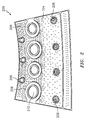
FIG. 2 illustrates an exemplary liner. -
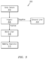
FIG. 3 illustrates a flow chart of an exemplary method for restoring/repairing a liner. - It is noted that various connections are set forth between elements in the following description and in the drawings (the contents of which are included in this disclosure by way of reference). It is noted that these connections are general and, unless specified otherwise, may be direct or indirect and that this specification is not intended to be limiting in this respect. A coupling between two or more entities may refer to a direct connection or an indirect connection. An indirect connection may incorporate one or more intervening entities.
- In accordance with various aspects of the disclosure, apparatuses, systems and methods are described for restoring/repairing a component of an engine, such as for example a liner of a combustor of an aircraft. In some embodiments, a surfacing weld build-up technique is used. The technique may incorporate the use of a laser weld powder or wire feed process and may be automated. In some embodiments, the technique provides for a controlled, precise, and repeatable low heat input weld to restore the component.
-
FIG. 1 is a side cutaway illustration of a gearedturbine engine 10. Thisturbine engine 10 extends along anaxial centerline 12 between anupstream airflow inlet 14 and adownstream airflow exhaust 16. Theturbine engine 10 includes afan section 18, acompressor section 19, acombustor section 20 and aturbine section 21. Thecompressor section 19 includes a low pressure compressor (LPC)section 19A and a high pressure compressor (HPC)section 19B. Theturbine section 21 includes a high pressure turbine (HPT)section 21A and a low pressure turbine (LPT)section 21B. - The engine sections 18-21 are arranged sequentially along the
centerline 12 within anengine housing 22. Each of the engine sections 18-19B, 21A and 21B includes a respective rotor 24-28. Each of these rotors 24-28 includes a plurality of rotor blades arranged circumferentially around and connected to one or more respective rotor disks. The rotor blades, for example, may be formed integral with or mechanically fastened, welded, brazed, adhered and/or otherwise attached to the respective rotor disk(s). - The
fan rotor 24 is connected to agear train 30, for example, through afan shaft 32. Thegear train 30 and theLPC rotor 25 are connected to and driven by theLPT rotor 28 through alow speed shaft 33. TheHPC rotor 26 is connected to and driven by theHPT rotor 27 through ahigh speed shaft 34. The shafts 32-34 are rotatably supported by a plurality ofbearings 36; e.g., rolling element and/or thrust bearings. Each of thesebearings 36 is connected to theengine housing 22 by at least one stationary structure such as, for example, an annular support strut. - During operation, air enters the
turbine engine 10 through theairflow inlet 14, and is directed through thefan section 18 and into acore gas path 38 and abypass gas path 40. The air within thecore gas path 38 may be referred to as "core air". The air within thebypass gas path 40 may be referred to as "bypass air". The core air is directed through the engine sections 19-21, and exits theturbine engine 10 through theairflow exhaust 16 to provide forward engine thrust. Within thecombustor section 20, fuel is injected into acombustion chamber 42 and mixed with compressed core air. This fuel-core air mixture is ignited to power theturbine engine 10. The bypass air is directed through thebypass gas path 40 and out of theturbine engine 10 through abypass nozzle 44 to provide additional forward engine thrust. This additional forward engine thrust may account for a majority (e.g., more than 70 percent) of total engine thrust. Alternatively, at least some of the bypass air may be directed out of theturbine engine 10 through a thrust reverser to provide reverse engine thrust. - The
engine 10 is illustrative. Aspects of the disclosure may be applied in connection with other engine types or configurations. - Referring to
FIG. 2 , a portion of aliner 200 is shown. Theliner 200 may be associated with an engine, such as theengine 10 ofFIG. 1 . - In some embodiments, the
liner 200 includes apanel 204. Thepanel 204 may take the form of a tiled structure that includes threadedstuds 206 that allow thepanel 204 to be bolted to a shell (not shown). In some embodiments, thepanel 204 includesgrommets 208. At the center of thegrommets 208 there may be dilution holes 210 that provide a combustion flow to thepanel 204 and the associated combustor (e.g.,combustor section 20 ofFIG. 1 ). In some embodiments, thepanel 204 interfaces to the high temperatures associated with the combustor. The liner 200 (e.g., the panel 204) may include one or more cooling pins/protrusions (not shown). - The
liner 200 is illustrative. Aspects of the disclosure may be applied in connection with other types or configurations of liners. - In some embodiments, a liner (e.g., liner 200) is fabricated using a casting technique. In some embodiments, the liner is relatively thin along a given dimension. For example, the liner may be approximately 0.040 inches (1.016 millimeters) thick.
- In some embodiments, the hot side/surface of a liner (e.g., the side/surface of the liner that faces the combustion environment) includes a coating (e.g., a thermal barrier coating (TBC)) that is comprised of one or more materials, such as a metal or a ceramic material. The cold side/surface of the liner (e.g., the side/surface of the liner that is exterior to, or furthest removed from, the combustion environment) that typically includes any
studs 206 or cooling pins/protrusions may be coated with aluminide. The aluminide coating operates as an insulator, making it more likely that the part 'overheats' and leads to failure. - In some embodiments, stripping away the coating on the cold side/surface can prove challenging and could result in a loss of base material or wall thickness associated with the liner. If base material is lost in an amount greater than a threshold it may be necessary to scrap or throw-away the liner.
- On the other hand, if the welding operation is performed on a liner that still has the cold side/surface coating (e.g., in an amount greater than a threshold), the quality of the liner following the welding operation may be less than ideal or inadequate (e.g., cracks or the impact of erosion may still be present in an amount greater than a threshold) and/or the cold side/surface coating may end up melting or diffusing the cold side coating into the base material. In one aspect, in embodiments that possess an aluminide coating, the aluminde migrates or diffuses into the base material.
- In accordance with aspects of the disclosure, a surface weld build-up technique may be used to repair/restore a combustor liner. In some embodiments, the technique may include a deposition of a material (e.g., a powder) subject to a low-heat input/weld. Such a low-heat input/weld provides adequate fusion (e.g., fusion in an amount greater than a threshold) without causing weld cracking or HAZ cracking, or at least ensures that any cracking that does occur is less than a threshold amount.
- Referring now to
FIG. 3 , a flow chart of anexemplary method 300 is shown. In some embodiments, themethod 300 is used to repair/restore a component or device. For example, themethod 300 may be used to repair/restore a liner of a combustor associated with an engine of an aircraft, and themethod 300 is described below in connection with such an exemplary application context. In some embodiments, themethod 300 is executed as part of a maintenance activity, such as a scheduled maintenance activity. - In
block 302, one or more details are stripped, or partially stripped, from the liner. As part ofblock 302, hardware (e.g., a nut) and/or one or more coatings associated with the liner may be stripped (e.g., partially stripped) or removed as part ofblock 302. For example, a coating associated with the hot side/surface of the liner may be removed as part ofblock 302. The coating associated with the cold side/surface of the liner may remain intact (e.g., might not be subjected to stripping or may be strip-free). - In
block 304, an inspection is performed. The inspection ofblock 304 may include an inspection for, e.g., erosion, cracking, etc. If the inspection ofblock 304 is negative (e.g., there is erosion, cracking, etc., that exceeds restoration/repair capabilities) the liner may be discarded or thrown-away inblock 306. Otherwise, flow may proceed fromblock 304 to block 308. - In
block 308, the liner is subjected to blending. The blending may entail applying an abrasive or stone to remove a stress concentrator or removing contamination. A wire brush may be applied to remove any grease/film that may be present. - In
block 310, the liner is subjected to a welding operation, such as for example an automated welding operation. As used herein, an automated welding operation means that the welding may be performed as a machine-driven operation. The welding operation may include, or be operative on the basis of, an application of a laser weld powder feed or plasma welding. Parameters or parameter values, such as temperature, beam length, intensity, etc., may be varied or selected based on an identification of the liner in order to maximize/increase/enhance the quality of the liner that is produced/restored followingblock 310. As part ofblock 310, the liner may be subjected to a low-heat input/weld as described above. - Technical effects and benefits of this disclosure include an enhanced restoration/repair technique as applied to, e.g., a combustor liner. Low temperatures may be used to restore/repair the combustor liner, thereby ensuring that a coating associated with the liner does not melt or deform in conjunction with a base material of the liner. Furthermore, a cold side/surface coating may remain substantially intact during the welding, thereby minimizing/reducing a loss of base material and extending the operational life of the combustor liner. Precise control in terms of a transfer of heat from a weld zone to a combustor liner is provided, such that the likelihood of cracking or thermal induced distortion is minimized.
- Aspects of the disclosure have been described in terms of illustrative embodiments thereof. Numerous other embodiments, modifications, and variations within the scope of the appended claims will occur to persons of ordinary skill in the art from a review of this disclosure. For example, one of ordinary skill in the art will appreciate that the steps described in conjunction with the illustrative figures may be performed in other than the recited order, and that one or more steps illustrated may be optional in accordance with aspects of the disclosure. One or more features described in connection with a first embodiment may be combined with one or more features of one or more additional embodiments.
Claims (15)
- A method for repairing or restoring a liner (200) associated with a combustor of an aircraft engine (10), comprising:at least partially stripping the liner (200) of at least one detail; andapplying an automated welding operation to the liner (200),wherein a coating of the liner (200) on a cold side of the liner (200) is retained on the liner (200) during the welding operation.
- The method of claim 1, wherein the stripping comprises a removal of hardware from the liner (200).
- The method of claim 2, wherein the hardware comprises a nut.
- The method of claim 1, 2 or 3, wherein a value for at least one parameter is selected as part of the welding operation.
- The method of claim 4, wherein the value is selected based on an identification of the liner (200).
- The method of claim 4 or 5, wherein the at least one parameter comprises at least one of temperature, beam length, or intensity.
- The method of any preceding claim, wherein the welding operation is performed at a temperature that ensures that fusion occurs in an amount greater than a first threshold.
- A liner (200) associated with a combustor of an aircraft engine (10), wherein the liner (200) is subject to at least a partial stripping of at least one detail, and wherein the liner (200) is subject to an automated welding operation, wherein a coating of the liner (200) on a cold side of the liner (200) is retained on the liner (200) during the welding operation.
- The method of any of claims 1 to 7, or the liner of claim 8, wherein the stripping comprises a removal of a nut from the liner (200).
- The method of any of claims 1 to 7, or the liner of claim 8 or 9, wherein the stripping comprises a removal of a second coating on a hot side of the liner (200).
- The method or liner of claim 10, wherein the second coating comprises at least one of a metal or a ceramic material.
- The method of any of claims 1 to 7, or the liner of any of claims 8 to 11, wherein the coating comprises a thermal barrier coating.
- The liner of any of claims 8 to 11, wherein the liner (200) is subjected to blending prior to being subjected to the welding operation; or
the method of claim 1, further comprising subjecting the liner (200) to blending prior to applying the welding operation. - The method of claim 13, further comprising:applying a brush to remove a film from the liner (200) prior to applying the welding operation.
- The method of any of claims 1 to 7, or the liner of any of claims 8 to 14, wherein the welding operation is based on at least one of an application of a laser weld powder feed or plasma welding.
Applications Claiming Priority (1)
| Application Number | Priority Date | Filing Date | Title |
|---|---|---|---|
| US14/635,639 US9987708B2 (en) | 2015-03-02 | 2015-03-02 | Automated weld repair of combustor liners |
Publications (1)
| Publication Number | Publication Date |
|---|---|
| EP3064310A1 true EP3064310A1 (en) | 2016-09-07 |
Family
ID=55453089
Family Applications (1)
| Application Number | Title | Priority Date | Filing Date |
|---|---|---|---|
| EP16158295.2A Withdrawn EP3064310A1 (en) | 2015-03-02 | 2016-03-02 | Automated weld repair of combustor liners |
Country Status (2)
| Country | Link |
|---|---|
| US (1) | US9987708B2 (en) |
| EP (1) | EP3064310A1 (en) |
Families Citing this family (5)
| Publication number | Priority date | Publication date | Assignee | Title |
|---|---|---|---|---|
| US20160195273A1 (en) * | 2014-12-23 | 2016-07-07 | United Technologies Corporation | Combustor wall with metallic coating on cold side |
| US20180355477A1 (en) * | 2017-06-07 | 2018-12-13 | Pratt & Whitney Canada Corp. | Thermal coating system with aluminide |
| US11407067B2 (en) * | 2018-06-29 | 2022-08-09 | Pratt & Whitney Canada Corp. | Method for repairing a part |
| US11339966B2 (en) | 2018-08-21 | 2022-05-24 | General Electric Company | Flow control wall for heat engine |
| US11029027B2 (en) * | 2018-10-03 | 2021-06-08 | Raytheon Technologies Corporation | Dilution/effusion hole pattern for thick combustor panels |
Citations (4)
| Publication number | Priority date | Publication date | Assignee | Title |
|---|---|---|---|---|
| EP0786304A1 (en) * | 1996-01-16 | 1997-07-30 | United Technologies Corporation | Variable polarity arc technology for the repair of coated articles |
| EP1076158A1 (en) * | 1999-08-11 | 2001-02-14 | General Electric Company | Gas turbine component having location-dependent protective coatings thereon |
| EP2466070A2 (en) * | 2010-12-20 | 2012-06-20 | General Electric Company | Method of repairing a transition piece of a gas turbine engine |
| US20140174091A1 (en) * | 2012-12-21 | 2014-06-26 | United Technologies Corporation | Repair procedure for a gas turbine engine via variable polarity welding |
Family Cites Families (17)
| Publication number | Priority date | Publication date | Assignee | Title |
|---|---|---|---|---|
| US4942732A (en) * | 1987-08-17 | 1990-07-24 | Barson Corporation | Refractory metal composite coated article |
| US5584663A (en) | 1994-08-15 | 1996-12-17 | General Electric Company | Environmentally-resistant turbine blade tip |
| US6054672A (en) | 1998-09-15 | 2000-04-25 | Chromalloy Gas Turbine Corporation | Laser welding superalloy articles |
| US6302649B1 (en) | 1999-10-04 | 2001-10-16 | General Electric Company | Superalloy weld composition and repaired turbine engine component |
| US6530971B1 (en) | 2001-01-29 | 2003-03-11 | General Electric Company | Nickel-base braze material and braze repair method |
| US6925810B2 (en) | 2002-11-08 | 2005-08-09 | Honeywell International, Inc. | Gas turbine engine transition liner assembly and repair |
| US7146725B2 (en) | 2003-05-06 | 2006-12-12 | Siemens Power Generation, Inc. | Repair of combustion turbine components |
| US7484651B2 (en) | 2004-10-22 | 2009-02-03 | Electric Power Research Institute, Inc. | Method to join or repair superalloy hot section turbine components using hot isostatic processing |
| US7966707B2 (en) | 2005-05-06 | 2011-06-28 | United Technologies Corporation | Method for repairing superalloy components using inserts |
| US20090113706A1 (en) | 2007-11-06 | 2009-05-07 | General Electric Company | Craze crack repair of combustor liners |
| US8397511B2 (en) * | 2009-05-19 | 2013-03-19 | General Electric Company | System and method for cooling a wall of a gas turbine combustor |
| US8373089B2 (en) * | 2009-08-31 | 2013-02-12 | General Electric Company | Combustion cap effusion plate laser weld repair |
| US8904635B2 (en) * | 2010-11-04 | 2014-12-09 | General Electric Company | Method for servicing a turbine part |
| JP5726545B2 (en) * | 2011-01-24 | 2015-06-03 | 株式会社東芝 | Transition piece damage repair method and transition piece |
| BRPI1101402A2 (en) | 2011-03-29 | 2013-06-04 | Mahle Metal Leve Sa | sliding element |
| US9289854B2 (en) | 2012-09-12 | 2016-03-22 | Siemens Energy, Inc. | Automated superalloy laser cladding with 3D imaging weld path control |
| US20140216042A1 (en) | 2012-09-28 | 2014-08-07 | United Technologies Corporation | Combustor component with cooling holes formed by additive manufacturing |
-
2015
- 2015-03-02 US US14/635,639 patent/US9987708B2/en active Active
-
2016
- 2016-03-02 EP EP16158295.2A patent/EP3064310A1/en not_active Withdrawn
Patent Citations (4)
| Publication number | Priority date | Publication date | Assignee | Title |
|---|---|---|---|---|
| EP0786304A1 (en) * | 1996-01-16 | 1997-07-30 | United Technologies Corporation | Variable polarity arc technology for the repair of coated articles |
| EP1076158A1 (en) * | 1999-08-11 | 2001-02-14 | General Electric Company | Gas turbine component having location-dependent protective coatings thereon |
| EP2466070A2 (en) * | 2010-12-20 | 2012-06-20 | General Electric Company | Method of repairing a transition piece of a gas turbine engine |
| US20140174091A1 (en) * | 2012-12-21 | 2014-06-26 | United Technologies Corporation | Repair procedure for a gas turbine engine via variable polarity welding |
Also Published As
| Publication number | Publication date |
|---|---|
| US9987708B2 (en) | 2018-06-05 |
| US20160256957A1 (en) | 2016-09-08 |
Similar Documents
| Publication | Publication Date | Title |
|---|---|---|
| EP2113634B1 (en) | Method of repairing a gas turbine engine case with replaced flange using cold metal transfer | |
| CN102601571B (en) | Damage-repairing method of transition piece and transition piece | |
| US7959409B2 (en) | Repaired vane assemblies and methods of repairing vane assemblies | |
| EP3415718B1 (en) | Gas turbine engine components with air-cooling features, and related methods of manufacturing the same | |
| US8510926B2 (en) | Method for repairing a gas turbine engine component | |
| EP3738708B1 (en) | Cast component for a gas turbine engine with non-fusion weldable nickel castings | |
| US20090026182A1 (en) | In-situ brazing methods for repairing gas turbine engine components | |
| US9987708B2 (en) | Automated weld repair of combustor liners | |
| US20080216300A1 (en) | Splitter fairing repair | |
| EP1099508B1 (en) | Turbine nozzle segment and method of repairing same | |
| CN101508070A (en) | Methods of repairing engine components | |
| EP3292939B1 (en) | Rotary friction welding method ; corresponding rotor disc and rotor assembly | |
| EP3486028A1 (en) | Repair of components using additive manufacturing with in-situ cold working | |
| RU2627088C2 (en) | Method for welding and building up metal components made of aluminium by the method of arc welding by metallic electrode in the medium of inert gas with pulsed current and pulsed filler wire | |
| EP3056664B1 (en) | Method of friction welding a set of rotor blades to a rotor disk | |
| EP2551457A2 (en) | Vane assembly and method of forming a vane assembly for a gas turbine engine | |
| US20180085867A1 (en) | Method involving friction plug welding a flange | |
| EP2113633A2 (en) | Method to weld repair blade outer air seals | |
| KR102775187B1 (en) | Tip repair of turbine components using composite tip boron-based pre-sintered preforms | |
| EP3056590A1 (en) | Blade restoration using shroud plating and obtained product | |
| JP5254116B2 (en) | Damage repair method for high temperature parts and high temperature parts | |
| EP3715043A1 (en) | Aftermarket repair process for a fuel nozzle guide heat shield of a gas turbine engine | |
| EP3054028A1 (en) | Hot section repair of metallic coatings |
Legal Events
| Date | Code | Title | Description |
|---|---|---|---|
| PUAI | Public reference made under article 153(3) epc to a published international application that has entered the european phase |
Free format text: ORIGINAL CODE: 0009012 |
|
| AK | Designated contracting states |
Kind code of ref document: A1 Designated state(s): AL AT BE BG CH CY CZ DE DK EE ES FI FR GB GR HR HU IE IS IT LI LT LU LV MC MK MT NL NO PL PT RO RS SE SI SK SM TR |
|
| AX | Request for extension of the european patent |
Extension state: BA ME |
|
| RAP1 | Party data changed (applicant data changed or rights of an application transferred) |
Owner name: UNITED TECHNOLOGIES CORPORATION |
|
| 17P | Request for examination filed |
Effective date: 20170303 |
|
| RBV | Designated contracting states (corrected) |
Designated state(s): AL AT BE BG CH CY CZ DE DK EE ES FI FR GB GR HR HU IE IS IT LI LT LU LV MC MK MT NL NO PL PT RO RS SE SI SK SM TR |
|
| STAA | Information on the status of an ep patent application or granted ep patent |
Free format text: STATUS: THE APPLICATION IS DEEMED TO BE WITHDRAWN |
|
| 18D | Application deemed to be withdrawn |
Effective date: 20170308 |