EP3056664B1 - Method of friction welding a set of rotor blades to a rotor disk - Google Patents
Method of friction welding a set of rotor blades to a rotor disk Download PDFInfo
- Publication number
- EP3056664B1 EP3056664B1 EP16155713.7A EP16155713A EP3056664B1 EP 3056664 B1 EP3056664 B1 EP 3056664B1 EP 16155713 A EP16155713 A EP 16155713A EP 3056664 B1 EP3056664 B1 EP 3056664B1
- Authority
- EP
- European Patent Office
- Prior art keywords
- rotor
- preform
- rotor blades
- blades
- disk
- Prior art date
- Legal status (The legal status is an assumption and is not a legal conclusion. Google has not performed a legal analysis and makes no representation as to the accuracy of the status listed.)
- Active
Links
- 238000000034 method Methods 0.000 title claims description 46
- 238000003466 welding Methods 0.000 title claims description 34
- 239000000463 material Substances 0.000 claims description 13
- 238000004519 manufacturing process Methods 0.000 claims description 6
- 238000003825 pressing Methods 0.000 claims description 3
- 238000003754 machining Methods 0.000 claims description 2
- 239000007789 gas Substances 0.000 description 5
- 238000010586 diagram Methods 0.000 description 3
- 239000000203 mixture Substances 0.000 description 3
- 239000011261 inert gas Substances 0.000 description 2
- 238000005219 brazing Methods 0.000 description 1
- 238000002485 combustion reaction Methods 0.000 description 1
- 238000004891 communication Methods 0.000 description 1
- 238000001816 cooling Methods 0.000 description 1
- 239000000446 fuel Substances 0.000 description 1
- 229910052751 metal Inorganic materials 0.000 description 1
- 239000002184 metal Substances 0.000 description 1
- 230000002093 peripheral effect Effects 0.000 description 1
- 238000005096 rolling process Methods 0.000 description 1
- 238000003756 stirring Methods 0.000 description 1
- WFKWXMTUELFFGS-UHFFFAOYSA-N tungsten Chemical compound [W] WFKWXMTUELFFGS-UHFFFAOYSA-N 0.000 description 1
- 229910052721 tungsten Inorganic materials 0.000 description 1
- 239000010937 tungsten Substances 0.000 description 1
- 238000011144 upstream manufacturing Methods 0.000 description 1
- XLYOFNOQVPJJNP-UHFFFAOYSA-N water Substances O XLYOFNOQVPJJNP-UHFFFAOYSA-N 0.000 description 1
Images


Classifications
-
- F—MECHANICAL ENGINEERING; LIGHTING; HEATING; WEAPONS; BLASTING
- F01—MACHINES OR ENGINES IN GENERAL; ENGINE PLANTS IN GENERAL; STEAM ENGINES
- F01D—NON-POSITIVE DISPLACEMENT MACHINES OR ENGINES, e.g. STEAM TURBINES
- F01D5/00—Blades; Blade-carrying members; Heating, heat-insulating, cooling or antivibration means on the blades or the members
- F01D5/30—Fixing blades to rotors; Blade roots ; Blade spacers
- F01D5/3061—Fixing blades to rotors; Blade roots ; Blade spacers by welding, brazing
-
- B—PERFORMING OPERATIONS; TRANSPORTING
- B23—MACHINE TOOLS; METAL-WORKING NOT OTHERWISE PROVIDED FOR
- B23K—SOLDERING OR UNSOLDERING; WELDING; CLADDING OR PLATING BY SOLDERING OR WELDING; CUTTING BY APPLYING HEAT LOCALLY, e.g. FLAME CUTTING; WORKING BY LASER BEAM
- B23K20/00—Non-electric welding by applying impact or other pressure, with or without the application of heat, e.g. cladding or plating
- B23K20/12—Non-electric welding by applying impact or other pressure, with or without the application of heat, e.g. cladding or plating the heat being generated by friction; Friction welding
- B23K20/1205—Non-electric welding by applying impact or other pressure, with or without the application of heat, e.g. cladding or plating the heat being generated by friction; Friction welding using translation movement
-
- B—PERFORMING OPERATIONS; TRANSPORTING
- B23—MACHINE TOOLS; METAL-WORKING NOT OTHERWISE PROVIDED FOR
- B23K—SOLDERING OR UNSOLDERING; WELDING; CLADDING OR PLATING BY SOLDERING OR WELDING; CUTTING BY APPLYING HEAT LOCALLY, e.g. FLAME CUTTING; WORKING BY LASER BEAM
- B23K20/00—Non-electric welding by applying impact or other pressure, with or without the application of heat, e.g. cladding or plating
- B23K20/12—Non-electric welding by applying impact or other pressure, with or without the application of heat, e.g. cladding or plating the heat being generated by friction; Friction welding
- B23K20/129—Non-electric welding by applying impact or other pressure, with or without the application of heat, e.g. cladding or plating the heat being generated by friction; Friction welding specially adapted for particular articles or workpieces
-
- B—PERFORMING OPERATIONS; TRANSPORTING
- B23—MACHINE TOOLS; METAL-WORKING NOT OTHERWISE PROVIDED FOR
- B23P—METAL-WORKING NOT OTHERWISE PROVIDED FOR; COMBINED OPERATIONS; UNIVERSAL MACHINE TOOLS
- B23P15/00—Making specific metal objects by operations not covered by a single other subclass or a group in this subclass
- B23P15/006—Making specific metal objects by operations not covered by a single other subclass or a group in this subclass turbine wheels
-
- B—PERFORMING OPERATIONS; TRANSPORTING
- B23—MACHINE TOOLS; METAL-WORKING NOT OTHERWISE PROVIDED FOR
- B23P—METAL-WORKING NOT OTHERWISE PROVIDED FOR; COMBINED OPERATIONS; UNIVERSAL MACHINE TOOLS
- B23P6/00—Restoring or reconditioning objects
- B23P6/002—Repairing turbine components, e.g. moving or stationary blades, rotors
- B23P6/005—Repairing turbine components, e.g. moving or stationary blades, rotors using only replacement pieces of a particular form
-
- F—MECHANICAL ENGINEERING; LIGHTING; HEATING; WEAPONS; BLASTING
- F01—MACHINES OR ENGINES IN GENERAL; ENGINE PLANTS IN GENERAL; STEAM ENGINES
- F01D—NON-POSITIVE DISPLACEMENT MACHINES OR ENGINES, e.g. STEAM TURBINES
- F01D5/00—Blades; Blade-carrying members; Heating, heat-insulating, cooling or antivibration means on the blades or the members
- F01D5/005—Repairing methods or devices
-
- F—MECHANICAL ENGINEERING; LIGHTING; HEATING; WEAPONS; BLASTING
- F01—MACHINES OR ENGINES IN GENERAL; ENGINE PLANTS IN GENERAL; STEAM ENGINES
- F01D—NON-POSITIVE DISPLACEMENT MACHINES OR ENGINES, e.g. STEAM TURBINES
- F01D5/00—Blades; Blade-carrying members; Heating, heat-insulating, cooling or antivibration means on the blades or the members
- F01D5/02—Blade-carrying members, e.g. rotors
-
- F—MECHANICAL ENGINEERING; LIGHTING; HEATING; WEAPONS; BLASTING
- F01—MACHINES OR ENGINES IN GENERAL; ENGINE PLANTS IN GENERAL; STEAM ENGINES
- F01D—NON-POSITIVE DISPLACEMENT MACHINES OR ENGINES, e.g. STEAM TURBINES
- F01D5/00—Blades; Blade-carrying members; Heating, heat-insulating, cooling or antivibration means on the blades or the members
- F01D5/34—Rotor-blade aggregates of unitary construction, e.g. formed of sheet laminae
-
- F—MECHANICAL ENGINEERING; LIGHTING; HEATING; WEAPONS; BLASTING
- F04—POSITIVE - DISPLACEMENT MACHINES FOR LIQUIDS; PUMPS FOR LIQUIDS OR ELASTIC FLUIDS
- F04D—NON-POSITIVE-DISPLACEMENT PUMPS
- F04D29/00—Details, component parts, or accessories
- F04D29/26—Rotors specially for elastic fluids
- F04D29/32—Rotors specially for elastic fluids for axial flow pumps
- F04D29/321—Rotors specially for elastic fluids for axial flow pumps for axial flow compressors
- F04D29/322—Blade mountings
-
- F—MECHANICAL ENGINEERING; LIGHTING; HEATING; WEAPONS; BLASTING
- F04—POSITIVE - DISPLACEMENT MACHINES FOR LIQUIDS; PUMPS FOR LIQUIDS OR ELASTIC FLUIDS
- F04D—NON-POSITIVE-DISPLACEMENT PUMPS
- F04D29/00—Details, component parts, or accessories
- F04D29/60—Mounting; Assembling; Disassembling
- F04D29/64—Mounting; Assembling; Disassembling of axial pumps
- F04D29/644—Mounting; Assembling; Disassembling of axial pumps especially adapted for elastic fluid pumps
-
- B—PERFORMING OPERATIONS; TRANSPORTING
- B23—MACHINE TOOLS; METAL-WORKING NOT OTHERWISE PROVIDED FOR
- B23K—SOLDERING OR UNSOLDERING; WELDING; CLADDING OR PLATING BY SOLDERING OR WELDING; CUTTING BY APPLYING HEAT LOCALLY, e.g. FLAME CUTTING; WORKING BY LASER BEAM
- B23K2101/00—Articles made by soldering, welding or cutting
- B23K2101/001—Turbines
-
- F—MECHANICAL ENGINEERING; LIGHTING; HEATING; WEAPONS; BLASTING
- F05—INDEXING SCHEMES RELATING TO ENGINES OR PUMPS IN VARIOUS SUBCLASSES OF CLASSES F01-F04
- F05D—INDEXING SCHEME FOR ASPECTS RELATING TO NON-POSITIVE-DISPLACEMENT MACHINES OR ENGINES, GAS-TURBINES OR JET-PROPULSION PLANTS
- F05D2220/00—Application
- F05D2220/30—Application in turbines
- F05D2220/32—Application in turbines in gas turbines
- F05D2220/323—Application in turbines in gas turbines for aircraft propulsion, e.g. jet engines
-
- F—MECHANICAL ENGINEERING; LIGHTING; HEATING; WEAPONS; BLASTING
- F05—INDEXING SCHEMES RELATING TO ENGINES OR PUMPS IN VARIOUS SUBCLASSES OF CLASSES F01-F04
- F05D—INDEXING SCHEME FOR ASPECTS RELATING TO NON-POSITIVE-DISPLACEMENT MACHINES OR ENGINES, GAS-TURBINES OR JET-PROPULSION PLANTS
- F05D2220/00—Application
- F05D2220/30—Application in turbines
- F05D2220/36—Application in turbines specially adapted for the fan of turbofan engines
-
- F—MECHANICAL ENGINEERING; LIGHTING; HEATING; WEAPONS; BLASTING
- F05—INDEXING SCHEMES RELATING TO ENGINES OR PUMPS IN VARIOUS SUBCLASSES OF CLASSES F01-F04
- F05D—INDEXING SCHEME FOR ASPECTS RELATING TO NON-POSITIVE-DISPLACEMENT MACHINES OR ENGINES, GAS-TURBINES OR JET-PROPULSION PLANTS
- F05D2230/00—Manufacture
- F05D2230/20—Manufacture essentially without removing material
- F05D2230/23—Manufacture essentially without removing material by permanently joining parts together
- F05D2230/232—Manufacture essentially without removing material by permanently joining parts together by welding
- F05D2230/236—Diffusion bonding
-
- F—MECHANICAL ENGINEERING; LIGHTING; HEATING; WEAPONS; BLASTING
- F05—INDEXING SCHEMES RELATING TO ENGINES OR PUMPS IN VARIOUS SUBCLASSES OF CLASSES F01-F04
- F05D—INDEXING SCHEME FOR ASPECTS RELATING TO NON-POSITIVE-DISPLACEMENT MACHINES OR ENGINES, GAS-TURBINES OR JET-PROPULSION PLANTS
- F05D2230/00—Manufacture
- F05D2230/20—Manufacture essentially without removing material
- F05D2230/23—Manufacture essentially without removing material by permanently joining parts together
- F05D2230/232—Manufacture essentially without removing material by permanently joining parts together by welding
- F05D2230/239—Inertia or friction welding
-
- F—MECHANICAL ENGINEERING; LIGHTING; HEATING; WEAPONS; BLASTING
- F05—INDEXING SCHEMES RELATING TO ENGINES OR PUMPS IN VARIOUS SUBCLASSES OF CLASSES F01-F04
- F05D—INDEXING SCHEME FOR ASPECTS RELATING TO NON-POSITIVE-DISPLACEMENT MACHINES OR ENGINES, GAS-TURBINES OR JET-PROPULSION PLANTS
- F05D2240/00—Components
- F05D2240/20—Rotors
- F05D2240/30—Characteristics of rotor blades, i.e. of any element transforming dynamic fluid energy to or from rotational energy and being attached to a rotor
Definitions
- This disclosure relates generally to a method of providing an integrally bladed rotor according to the preamble of claim 1 (see for example EP 0 458 630 A1 ), and to a method of manufacturing or repairing an integrally bladed rotor for a turbine engine (see claim 13) and, more particularly, to friction welding rotor blades to a rotor disk.
- An integrally bladed rotor includes a rotor disk and a plurality of rotor blades.
- the rotor blades are disposed around and may be bonded to or formed integral with the rotor disk.
- each rotor blade is individually linear friction welded to the rotor disk. Such a method, however, may be time consuming and expensive since each blade is welded to the rotor disk in a separate and discrete step.
- EP 0850718 A1 , EP 2339117 A2 , EP 1239116 A2 and EP 2339116 A2 describe methods of providing a rotor on which blades are assembled.
- a method of providing an integrally bladed rotor is provided as claimed in claim 1.
- a method of manufacturing or repairing an integrally bladed rotor for a turbine engine is provided as claimed in claim 13, using the above defined methods.
- the welding may be or include linear friction welding and/or any other welding process.
- the weld plane may be planar or parti-cylindrical.
- the method may include at least partially removing a set of rotor blades from the rotor disk prior to the arranging of the preform rotor blades relative to the rotor disk.
- the preform rotor blades may be respectively welded to the rotor disk at locations from which the rotor blades were disposed before being removed.
- An adjacent pair of the collar segments may be bonded together.
- the adjacent pair of the collar segments may be mechanically joined together.
- the collar may include a gripping feature.
- the collars may be interconnected by a fixture used to hold and move the preform rotor blades during the (e.g., linear friction) welding.
- the rotor disk may include a set of preform rotor blade bases to which the preform rotor blades are respectively (e.g., linear friction) welded.
- the (e.g., linear friction) welding may include: holding the rotor disk stationary; oscillating the preform rotor blades along a weld plane; and pressing the oscillating preform rotor blades against the stationary rotor disk.
- the rotor blades may be configured as compressor blades for a turbine engine.
- the rotor blades may be configured as turbine blades for a turbine engine.
- the rotor blades may be configured as fan blades for a turbine engine.
- the present invention includes methods of manufacturing, repairing or otherwise providing an integrally bladed rotor (IBR).
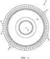
- An exemplary integrally bladed rotor 20 is illustrated in FIG. 1 .
- this rotor 20 is described below as an integrally bladed rotor for a turbine engine.
- such a rotor may alternatively be configured for various other types of rotary machines such as, but not limited to, wind turbines, water turbines, propeller systems, etc.
- the rotor 20 includes a rotor disk 22 and a plurality of rotor blades 24; e.g., airfoils.
- the rotor blades 24 may be configured as compressor blades, turbine blades or fan blades.
- the rotor blades 24 are arranged circumferentially around a rotational axis 26 of the rotor disk 22.
- the rotor blades 24 are integrally connected with a radial outer peripheral portion of the rotor disk 22.
- some or all of the rotor blades 24 or outer portions thereof are friction welded (e.g., linear friction welded) to the rotor disk 22 using methods as described below.
- One or more of the rotor blades 24 may alternatively, of course, be formed (e.g., cast, forged, machined) integral with the rotor disk 22 where, for example, the friction welding methods described below are utilized to repair a worn or damaged integrally bladed rotor.
- the rotor 20 may be manufactured or repaired by concurrently friction welding a set of two, three, four or more preform rotor blades to a rotor disk; e.g., the rotor disk 22.
- preform rotor blade may describe a partially formed rotor blade or outer portion of a rotor blade.
- a rotor blade or rotor blade portion may be considered “partially formed” where it has a general rotor blade configuration (e.g., shape, cooling features, etc.), but requires additional machining, heat treating, finishing and/or other material manipulation processes.
- a rotor blade or rotor blade portion may also be considered “partially formed” where it includes additional features such as, but not limited to, collar(s), weld constant(s), etc. for use in friction welding that rotor blade or rotor blade portion to a rotor disk, which features may later be removed.
- FIG. 2 illustrates an exemplary set of preform rotor blades 28 arranged next to the rotor disk 22, which includes a corresponding set of preform rotor blade bases 30. These preform rotor blade bases 30 may be integrally formed with the rotor disk 22.
- Each of the preform rotor blade bases 30 includes a rotor stub 32 and weld constant 34.
- the rotor stub 32 extends radially out from the rotor disk 22 to the weld constant 34.
- the weld constant 34 may have approximately the same geometry as a similarly situated portion of one of the rotor blades 24; see FIG. 1 .
- the weld constant 34 extends radially out from the rotor stub 32.
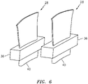
- each of the preform rotor blades 28 includes a weld constant 40.
- the weld constant 40 may have approximately the same geometry as a similarly situated portion of one of the rotor blades 24 (see FIG. 1 ) as well as a corresponding one of the weld constants 34.
- the weld constant 40 extends radially inward from the collar 36.
- Each of the weld constants 40 is operable to engage a corresponding one of the weld constants 34 on the rotor disk 22, or the rotor disk 22 itself, in such a fashion so as to friction weld the preform rotor blades 28 to the rotor disk 22 (e.g., see FIG. ).
- the weld constants 36 and 40 may melt and combine together during the friction welding. At least a portion of the melted and combined weld constants 36 and 40 may create weld flash, which may flow out between the collar(s) 36 and the rotor stubs 32. Material of the collars 36 and the rotor stubs 32 may also melt and combine together during the friction welding.
- the welded preform rotor blades 28 e.g., the collar(s), weld constant flash, etc.
- the preform rotor blade bases 30 e.g., the stubs, weld flash, etc.
- the welded preform rotor blades 28 and/or the preform rotor blade bases 30 may be further machined and/or otherwise finished and/or manipulated to provide the rotor blades 24 of FIG. 1 .
- FIG. 7 illustrates a system 42 for friction welding (e.g., linear friction welding) at least one set of two, three, four or more preform rotor blades 28 to a rotor disk 22.
- This system 42 includes a rotor disk fixture 44, a rotor blade fixture 46, a manipulator (e.g., oscillator) system 48 and a controller 50.
- a manipulator e.g., oscillator
- the rotor disk fixture 44 is configured to securely hold the rotor disk 22 during friction welding.
- the rotor disk fixture 44 may secure the rotor disk 22 to a ground 52 such that the rotor disk 22 is held stationary during friction welding.
- the rotor disk fixture 44 may be configured to adjust spatial orientation of the rotor disk 22 before, during and/or after a friction welding step.
- the rotor disk fixture 44 may be configured to rotate the rotor disk 22 about its rotational axis 26.
- the present disclosure is not limited to any particular rotor disk fixture 44 types or configurations.
- the rotor blade fixture 46 is configured to securely hold a set of preform rotor blades 28 during friction welding.
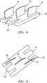
- the rotor blade fixture 46 may clamp onto opposing portions of the collar 36.
- the rotor blade fixture 46 may clamp onto a gripping feature 54 such as, for example, a protrusion that extends out from the collar 36 or formed in the collar 36 as illustrated in FIGS. 8 and 9 .
- the rotor blade fixture 46 may secure the preform rotor blades 28 to the manipulator system 48.
- the manipulator system 48 is configured to move the preform rotor blades 28 relative to the rotor disk 22.
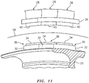
- the manipulator system 48 may oscillate the preform rotor blades 28 back and forth (e.g., linearly) along a weld plane 56 (see FIG. 2 ).
- This weld plane 56 may be planar as illustrated in FIG. 10 or parti-cylindrical as illustrated in FIG. 11 .
- the manipulator system 48 is also configured to press the oscillating preform rotor blades 28 (e.g., radially) against the rotor disk 22. More particularly, the manipulator system 48 is configured to press the weld constants 34 against the weld constants 40, which may cause the material of the weld constants 34 and 40 to melt and mix and thereby weld together.
- the controller 50 is in signal communication (e.g., hardwired and/or wirelessly connected) with at least the manipulator system 48.
- the controller 50 may be implemented with a combination of hardware and software.
- the hardware may include memory and at least one processing device, which may include one or more single-core and/or multi-core processors.
- the memory is configured to store software (e.g., program instructions) for execution by the processing device, which software execution may control and/or facilitate performance of one or more operations such as those described in the methods below.
- the memory may be a non-transitory computer readable medium configured as or that includes a volatile memory and/or a nonvolatile memory.
- the hardware may also or alternatively include analog and/or digital circuitry other than that described above.
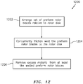
- FIG. 12 is a flow diagram of a method 1200 for providing an integrally bladed rotor such as the rotor 20.
- This method 1200 may be utilized for manufacturing a new integrally bladed rotor.
- the method 1200 may also or alternatively be used for repairing a worn or damaged integrally bladed rotor.
- a plurality of rotor blades may be at least partially removed (e.g., cut, machined, etc.) from the rotor disk 22, where at least one of these rotor blades may be damaged or worn.
- the preform rotor blades 28 may thereafter be friction welded to the rotor disk 22 using the method 1200 at locations from where the rotor blades were removed.
- a set of preform rotor blades 28 are arranged relative to the rotor disk 22.
- the preform rotor blades 28, for example, may be secured with the rotor blade fixture 46.
- the rotor blade fixture 46 may then be arranged next to locations to which the preform rotor blades 28 are to be welded to the rotor disk 22; e.g., locations from which worn or damaged rotor blades were removed.
- the preform rotor blades 28 are concurrently friction welded (e.g., linear friction welded) to the rotor disk 22.
- the manipulator system 48 may be signaled by the controller 50 to oscillate the preform rotor blades 28 back and forth linearly along the weld plane 56 relative to the stationary rotor disk 22.
- the manipulator system 48 may also be signaled by the controller 50 to press the oscillating preform rotor blades 28 and, more particularly, the weld constants 40 against the stationary preform rotor blade bases 30 and, more particularly, the weld constants 34.
- Friction heat generated between the weld constants 34 and 40 may melt the material of the weld constants 34 and 40 and thereby mix the melted material together; i.e., friction weld the material together.
- the preform rotor blades 28 may be pressed against the rotor disk 22 until, for example, the collar 36 is adjacent (e.g., touches) or is welded to the rotor stubs 32.
- step 1206 excess material is removed from at least the welded preform rotor blades 28 and/or the preform rotor blade bases 30.
- Collar 36 material, stub 32 material, flash 34, 40 material, etc., for example, may be machined and/or otherwise removed to provide the rotor blades 24.
- the rotor blade 24 and/or rotor disk 22 material may also be heat treated or otherwise finished and/or manipulated.
- the collar 36 may be formed unitary with a plurality of the preform rotor blades 28.
- the collar 36 may include a plurality of discrete segments 38. Each of these collar segments 38 may be formed integral with a respective one of the preform rotor blades 28.
- the collar segments 38 may subsequently be interconnected together by bonding (e.g., welding, brazing, adhering, etc.) as illustrated in FIG. 4 and/or through a mechanical joint (e.g., a tongue and groove joint, fasteners, etc.) as illustrated in FIG. 5 .
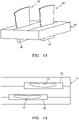
- each of the preform rotor blades 28 may be configured with its own respective collar 36. These collars 36 may then be functionally connected together by the rotor blade fixture 46 or another device as illustrated in FIGS. 13 and 14 .
- the foregoing methodology may also or alternatively be performed using one or more welding techniques other than that described above.
- Other suitable welding techniques may include, but not limited to, tungsten inert gas (TIG) welding, metal inert gas (MIG) welding, friction stir welding, etc.
- TIG tungsten inert gas
- MIG metal inert gas
- friction stir welding etc.
- the foregoing methodology may be performed using other material bonding processes such as, but not limited to, adhesion.
- the method and apparatuses of the present disclosure therefore are not limited to any particular bonding techniques, but may be preferably performed using linear friction welding.
- FIG. 15 is a side cutaway illustration of a geared turbine engine 58 with which an integrally blade rotor such as those described above may be configured.
- the turbine engine 58 extends along an axial centerline 60 between an upstream airflow inlet 62 and a downstream airflow exhaust 64.
- the turbine engine 58 includes a fan section 66, a compressor section 67, a combustor section 68 and a turbine section 69.
- the compressor section 67 includes a low pressure compressor (LPC) section 67A and a high pressure compressor (HPC) section 67B.
- the turbine section 69 includes a high pressure turbine (HPT) section 69A and a low pressure turbine (LPT) section 69B.
- the engine sections 66-69 are arranged sequentially along the centerline 60 within an engine housing 70.
- Each of the engine sections 66, 67A, 67B, 69A and 69B includes a respective rotor 72-76, one or more of which may be configured as or include the rotor 20.
- Each of these rotors 72-76 includes a plurality of rotor blades arranged circumferentially around and connected to one or more respective rotor disks.
- the rotor blades for example, may be formed integral with or mechanically fastened, welded, brazed, adhered and/or otherwise attached to the respective rotor disk(s).
- the fan rotor 72 is connected to a gear train 78, for example, through a fan shaft 80.
- the gear train 78 and the LPC rotor 73 are connected to and driven by the LPT rotor 76 through a low speed shaft 81.
- the HPC rotor 74 is connected to and driven by the HPT rotor 75 through a high speed shaft 82.
- the shafts 80-82 are rotatably supported by a plurality of bearings 84; e.g., rolling element and/or thrust bearings.
- Each of these bearings 84 is connected to the engine housing 70 by at least one stationary structure such as, for example, an annular support strut.
- the air within the core gas path 84 may be referred to as "core air”.
- the air within the bypass gas path 86 may be referred to as "bypass air”.
- the core air is directed through the engine sections 67-69, and exits the turbine engine 58 through the airflow exhaust 64 to provide forward engine thrust.
- fuel is injected into a combustion chamber 88 and mixed with the core air. This fuel-core air mixture is ignited to power the turbine engine 58.
- bypass air is directed through the bypass gas path 86 and out of the turbine engine 58 through a bypass nozzle 90 to provide additional forward engine thrust.
- bypass air may be directed out of the turbine engine 58 through a thrust reverser to provide reverse engine thrust.
- the rotor 20 may be included in various turbine engines other than the one described above as well as in other types of rotational equipment.
- the rotor 20, for example, may be included in a geared turbine engine where a gear train connects one or more shafts to one or more rotors in a fan section, a compressor section and/or any other engine section.
- the rotor 20 may be included in a turbine engine configured without a gear train.
- the rotor 20 may be included in a geared or non-geared turbine engine configured with a single spool, with two spools (e.g., see FIG. 15 ), or with more than two spools.
- the turbine engine may be configured as a turbofan engine, a turbojet engine, a propfan engine, a pusher fan engine or any other type of turbine engine.
- the present invention therefore is not limited to any particular types or configurations of turbine engines or rotational equipment.
Description
- This disclosure relates generally to a method of providing an integrally bladed rotor according to the preamble of claim 1 (see for example
EP 0 458 630 A1 ), and to a method of manufacturing or repairing an integrally bladed rotor for a turbine engine (see claim 13) and, more particularly, to friction welding rotor blades to a rotor disk. - An integrally bladed rotor includes a rotor disk and a plurality of rotor blades. The rotor blades are disposed around and may be bonded to or formed integral with the rotor disk. In one bonding method, each rotor blade is individually linear friction welded to the rotor disk. Such a method, however, may be time consuming and expensive since each blade is welded to the rotor disk in a separate and discrete step.
- There is a need in the art for improved methods and systems for welding rotor blades to a rotor disk in manufacture and repair of integrally bladed rotors.
-
EP 0850718 A1 ,EP 2339117 A2 ,EP 1239116 A2 andEP 2339116 A2 describe methods of providing a rotor on which blades are assembled. - According to an aspect of the invention, a method of providing an integrally bladed rotor is provided as claimed in claim 1.
- Further embodiments of the present invention are defined in the appended claims.
- According to a second aspect of the invention a method of manufacturing or repairing an integrally bladed rotor for a turbine engine is provided as claimed in claim 13, using the above defined methods.
- The welding may be or include linear friction welding and/or any other welding process.
- The weld plane may be planar or parti-cylindrical.
- The method may include at least partially removing a set of rotor blades from the rotor disk prior to the arranging of the preform rotor blades relative to the rotor disk. The preform rotor blades may be respectively welded to the rotor disk at locations from which the rotor blades were disposed before being removed.
- An adjacent pair of the collar segments may be bonded together. In addition or alternatively, the adjacent pair of the collar segments may be mechanically joined together.
- The collar may include a gripping feature.
- The collars may be interconnected by a fixture used to hold and move the preform rotor blades during the (e.g., linear friction) welding.
- The rotor disk may include a set of preform rotor blade bases to which the preform rotor blades are respectively (e.g., linear friction) welded.
- The (e.g., linear friction) welding may include: holding the rotor disk stationary; oscillating the preform rotor blades along a weld plane; and pressing the oscillating preform rotor blades against the stationary rotor disk.
- The rotor blades may be configured as compressor blades for a turbine engine.
- Alternatively, the rotor blades may be configured as turbine blades for a turbine engine.
- Alternatively, the rotor blades may be configured as fan blades for a turbine engine.
- The foregoing features and the operation of the invention will become more apparent in light of the following description and the accompanying drawings.
-
-
FIG. 1 is an illustration of an integrally bladed rotor (IBR). -
FIG. 2 is a perspective illustration of a set of preform rotor blades arranged next to a rotor disk, only a portion of which is illustrated. -
FIGS. 3-6 are perspective illustrations of different sets of preform rotor blades. -
FIG. 7 is a block diagram of a system for friction welding a set of preform rotor blades to a rotor disk. -
FIGS. 8 and 9 are illustrations of another set of preform rotor blades. -
FIG. 10 is an illustration of a portion of the preform rotor blades and the rotor disk ofFIG. 2 . -
FIG. 11 is an illustration of a portion of another set of preform rotor blades arranged next to a rotor disk. -
FIG. 12 is a flow diagram of a method for providing an integrally bladed rotor. -
FIGS. 13 and 14 are illustrations of the preform rotor blades ofFIG. 6 configured with a rotor blade fixture. -
FIG. 15 is a side cutaway illustration of a geared turbine engine. - The present invention includes methods of manufacturing, repairing or otherwise providing an integrally bladed rotor (IBR). An exemplary integrally
bladed rotor 20 is illustrated inFIG. 1 . For ease of description, thisrotor 20 is described below as an integrally bladed rotor for a turbine engine. However, such a rotor may alternatively be configured for various other types of rotary machines such as, but not limited to, wind turbines, water turbines, propeller systems, etc. - The
rotor 20 includes arotor disk 22 and a plurality ofrotor blades 24; e.g., airfoils. Therotor blades 24 may be configured as compressor blades, turbine blades or fan blades. Therotor blades 24 are arranged circumferentially around arotational axis 26 of therotor disk 22. Therotor blades 24 are integrally connected with a radial outer peripheral portion of therotor disk 22. In particular, some or all of therotor blades 24 or outer portions thereof are friction welded (e.g., linear friction welded) to therotor disk 22 using methods as described below. One or more of therotor blades 24 may alternatively, of course, be formed (e.g., cast, forged, machined) integral with therotor disk 22 where, for example, the friction welding methods described below are utilized to repair a worn or damaged integrally bladed rotor. - The
rotor 20 may be manufactured or repaired by concurrently friction welding a set of two, three, four or more preform rotor blades to a rotor disk; e.g., therotor disk 22. The term "preform rotor blade" may describe a partially formed rotor blade or outer portion of a rotor blade. A rotor blade or rotor blade portion may be considered "partially formed" where it has a general rotor blade configuration (e.g., shape, cooling features, etc.), but requires additional machining, heat treating, finishing and/or other material manipulation processes. A rotor blade or rotor blade portion may also be considered "partially formed" where it includes additional features such as, but not limited to, collar(s), weld constant(s), etc. for use in friction welding that rotor blade or rotor blade portion to a rotor disk, which features may later be removed. -
FIG. 2 illustrates an exemplary set ofpreform rotor blades 28 arranged next to therotor disk 22, which includes a corresponding set of preformrotor blade bases 30. These preformrotor blade bases 30 may be integrally formed with therotor disk 22. Each of the preformrotor blade bases 30 includes arotor stub 32 andweld constant 34. Therotor stub 32 extends radially out from therotor disk 22 to theweld constant 34. The weld constant 34 may have approximately the same geometry as a similarly situated portion of one of therotor blades 24; seeFIG. 1 . Theweld constant 34 extends radially out from therotor stub 32. - The
preform rotor blades 28 are integrally connected (e.g., cast, forged and/or machined integral) with asingle collar 36; see alsoFIG. 3 . However, in other embodiments as shown inFIGS. 4-6 , one or more of thepreform rotor blades 28 may each be integrally connected with a respective collar segment 38 (seeFIGS. 4 and 5 ) or its own discrete collar 36 (seeFIG. 6 ). Referring again toFIG. 2 , each of thepreform rotor blades 28 includes a weld constant 40. The weld constant 40 may have approximately the same geometry as a similarly situated portion of one of the rotor blades 24 (seeFIG. 1 ) as well as a corresponding one of theweld constants 34. The weld constant 40 extends radially inward from thecollar 36. - Each of the weld constants 40 is operable to engage a corresponding one of the weld constants 34 on the
rotor disk 22, or therotor disk 22 itself, in such a fashion so as to friction weld thepreform rotor blades 28 to the rotor disk 22 (e.g., see FIG. ). For example, theweld constants weld constants collars 36 and the rotor stubs 32 may also melt and combine together during the friction welding. Subsequent to the friction welding, the welded preform rotor blades 28 (e.g., the collar(s), weld constant flash, etc.) and/or the preform rotor blade bases 30 (e.g., the stubs, weld flash, etc.) may be further machined and/or otherwise finished and/or manipulated to provide therotor blades 24 ofFIG. 1 . -
FIG. 7 illustrates asystem 42 for friction welding (e.g., linear friction welding) at least one set of two, three, four or morepreform rotor blades 28 to arotor disk 22. Thissystem 42 includes arotor disk fixture 44, arotor blade fixture 46, a manipulator (e.g., oscillator)system 48 and acontroller 50. - The
rotor disk fixture 44 is configured to securely hold therotor disk 22 during friction welding. Therotor disk fixture 44 may secure therotor disk 22 to aground 52 such that therotor disk 22 is held stationary during friction welding. However, therotor disk fixture 44 may be configured to adjust spatial orientation of therotor disk 22 before, during and/or after a friction welding step. Therotor disk fixture 44, for example, may be configured to rotate therotor disk 22 about itsrotational axis 26. Of course, the present disclosure is not limited to any particularrotor disk fixture 44 types or configurations. - The
rotor blade fixture 46 is configured to securely hold a set ofpreform rotor blades 28 during friction welding. Therotor blade fixture 46, for example, may clamp onto opposing portions of thecollar 36. Alternatively, therotor blade fixture 46 may clamp onto agripping feature 54 such as, for example, a protrusion that extends out from thecollar 36 or formed in thecollar 36 as illustrated inFIGS. 8 and 9 . Referring again toFIG. 7 , therotor blade fixture 46 may secure thepreform rotor blades 28 to themanipulator system 48. - The
manipulator system 48 is configured to move thepreform rotor blades 28 relative to therotor disk 22. Themanipulator system 48, for example, may oscillate thepreform rotor blades 28 back and forth (e.g., linearly) along a weld plane 56 (seeFIG. 2 ). Thisweld plane 56 may be planar as illustrated inFIG. 10 or parti-cylindrical as illustrated inFIG. 11 . Themanipulator system 48 is also configured to press the oscillating preform rotor blades 28 (e.g., radially) against therotor disk 22. More particularly, themanipulator system 48 is configured to press the weld constants 34 against the weld constants 40, which may cause the material of theweld constants - The
controller 50 is in signal communication (e.g., hardwired and/or wirelessly connected) with at least themanipulator system 48. Thecontroller 50 may be implemented with a combination of hardware and software. The hardware may include memory and at least one processing device, which may include one or more single-core and/or multi-core processors. The memory is configured to store software (e.g., program instructions) for execution by the processing device, which software execution may control and/or facilitate performance of one or more operations such as those described in the methods below. The memory may be a non-transitory computer readable medium configured as or that includes a volatile memory and/or a nonvolatile memory. The hardware may also or alternatively include analog and/or digital circuitry other than that described above. -
FIG. 12 is a flow diagram of amethod 1200 for providing an integrally bladed rotor such as therotor 20. Thismethod 1200 may be utilized for manufacturing a new integrally bladed rotor. Themethod 1200 may also or alternatively be used for repairing a worn or damaged integrally bladed rotor. In such embodiments, a plurality of rotor blades may be at least partially removed (e.g., cut, machined, etc.) from therotor disk 22, where at least one of these rotor blades may be damaged or worn. Thepreform rotor blades 28 may thereafter be friction welded to therotor disk 22 using themethod 1200 at locations from where the rotor blades were removed. - In
step 1202, a set ofpreform rotor blades 28 are arranged relative to therotor disk 22. Thepreform rotor blades 28, for example, may be secured with therotor blade fixture 46. Therotor blade fixture 46 may then be arranged next to locations to which thepreform rotor blades 28 are to be welded to therotor disk 22; e.g., locations from which worn or damaged rotor blades were removed. - In
step 1204, thepreform rotor blades 28 are concurrently friction welded (e.g., linear friction welded) to therotor disk 22. Themanipulator system 48, for example, may be signaled by thecontroller 50 to oscillate thepreform rotor blades 28 back and forth linearly along theweld plane 56 relative to thestationary rotor disk 22. Themanipulator system 48 may also be signaled by thecontroller 50 to press the oscillatingpreform rotor blades 28 and, more particularly, the weld constants 40 against the stationary preform rotor blade bases 30 and, more particularly, theweld constants 34. Friction heat generated between theweld constants weld constants preform rotor blades 28 may be pressed against therotor disk 22 until, for example, thecollar 36 is adjacent (e.g., touches) or is welded to the rotor stubs 32. - In
step 1206, excess material is removed from at least the weldedpreform rotor blades 28 and/or the preform rotor blade bases 30.Collar 36 material,stub 32 material,flash rotor blades 24. Of course, therotor blade 24 and/orrotor disk 22 material may also be heat treated or otherwise finished and/or manipulated. - In some embodiments, referring to
FIGS. 3 ,8 and 9 , thecollar 36 may be formed unitary with a plurality of thepreform rotor blades 28. In some embodiments, referring toFIGS. 4 and 5 , thecollar 36 may include a plurality ofdiscrete segments 38. Each of thesecollar segments 38 may be formed integral with a respective one of thepreform rotor blades 28. Thecollar segments 38 may subsequently be interconnected together by bonding (e.g., welding, brazing, adhering, etc.) as illustrated inFIG. 4 and/or through a mechanical joint (e.g., a tongue and groove joint, fasteners, etc.) as illustrated inFIG. 5 . - In some embodiments, referring to
FIG. 6 , each of thepreform rotor blades 28 may be configured with its ownrespective collar 36. Thesecollars 36 may then be functionally connected together by therotor blade fixture 46 or another device as illustrated inFIGS. 13 and 14 . - The foregoing methodology may also or alternatively be performed using one or more welding techniques other than that described above. Other suitable welding techniques may include, but not limited to, tungsten inert gas (TIG) welding, metal inert gas (MIG) welding, friction stir welding, etc. Furthermore, the foregoing methodology may be performed using other material bonding processes such as, but not limited to, adhesion. The method and apparatuses of the present disclosure therefore are not limited to any particular bonding techniques, but may be preferably performed using linear friction welding.
-
FIG. 15 is a side cutaway illustration of a gearedturbine engine 58 with which an integrally blade rotor such as those described above may be configured. Theturbine engine 58 extends along anaxial centerline 60 between anupstream airflow inlet 62 and adownstream airflow exhaust 64. Theturbine engine 58 includes afan section 66, acompressor section 67, acombustor section 68 and aturbine section 69. Thecompressor section 67 includes a low pressure compressor (LPC)section 67A and a high pressure compressor (HPC)section 67B. Theturbine section 69 includes a high pressure turbine (HPT)section 69A and a low pressure turbine (LPT)section 69B. - The engine sections 66-69 are arranged sequentially along the
centerline 60 within anengine housing 70. Each of theengine sections rotor 20. Each of these rotors 72-76 includes a plurality of rotor blades arranged circumferentially around and connected to one or more respective rotor disks. The rotor blades, for example, may be formed integral with or mechanically fastened, welded, brazed, adhered and/or otherwise attached to the respective rotor disk(s). - The
fan rotor 72 is connected to agear train 78, for example, through afan shaft 80. Thegear train 78 and theLPC rotor 73 are connected to and driven by theLPT rotor 76 through alow speed shaft 81. TheHPC rotor 74 is connected to and driven by theHPT rotor 75 through ahigh speed shaft 82. The shafts 80-82 are rotatably supported by a plurality ofbearings 84; e.g., rolling element and/or thrust bearings. Each of thesebearings 84 is connected to theengine housing 70 by at least one stationary structure such as, for example, an annular support strut. - During operation, air enters the
turbine engine 58 through theairflow inlet 62, and is directed through thefan section 66 and into acore gas path 84 and abypass gas path 86. The air within thecore gas path 84 may be referred to as "core air". The air within thebypass gas path 86 may be referred to as "bypass air". The core air is directed through the engine sections 67-69, and exits theturbine engine 58 through theairflow exhaust 64 to provide forward engine thrust. Within thecombustor section 68, fuel is injected into acombustion chamber 88 and mixed with the core air. This fuel-core air mixture is ignited to power theturbine engine 58. The bypass air is directed through thebypass gas path 86 and out of theturbine engine 58 through abypass nozzle 90 to provide additional forward engine thrust. Alternatively, at least some of the bypass air may be directed out of theturbine engine 58 through a thrust reverser to provide reverse engine thrust. - The
rotor 20 may be included in various turbine engines other than the one described above as well as in other types of rotational equipment. Therotor 20, for example, may be included in a geared turbine engine where a gear train connects one or more shafts to one or more rotors in a fan section, a compressor section and/or any other engine section. Alternatively, therotor 20 may be included in a turbine engine configured without a gear train. Therotor 20 may be included in a geared or non-geared turbine engine configured with a single spool, with two spools (e.g., seeFIG. 15 ), or with more than two spools. The turbine engine may be configured as a turbofan engine, a turbojet engine, a propfan engine, a pusher fan engine or any other type of turbine engine. The present invention therefore is not limited to any particular types or configurations of turbine engines or rotational equipment. - While various embodiments of the present invention have been disclosed, it will be apparent to those of ordinary skill in the art that many more embodiments and implementations are possible within the scope of the invention as defined in the appended claims.
Claims (14)
- A method of providing an integrally bladed rotor, comprising the steps of:arranging a set of preform rotor blades (28) relative to a rotor disk (22);concurrently welding the preform rotor blades (28) to the rotor disk (22),wherein the method is characterised in that:the preform rotor blades (28) are interconnected by a collar (36), and either the collar (36) is formed as a unitary body with the preform rotor blades (28), or the collar (36) includes a plurality of collar segments (38) and each of the collar segments (38) is formed as a unitary body with a respective one of the preform rotor blades (28); oreach of the preform rotor blades (28) is formed integral with a respective one of a plurality of interconnected collars (36), and the method further comprises:
machining or otherwise removing excess material from at least the welded preform rotor blades (28) to respectively form a set of blades (24). - The method of claim 1, wherein the welding comprises linear friction welding.
- The method of claim 1 or 2, wherein a weld plane between preform rotor blades (28) and the rotor disk (22) is planar.
- The method of claim 1 or 2, wherein a weld plane between the preform rotor blades (28) and the rotor disk (22) is partly-cylindrical.
- The method of any preceding claim, wherein the collar (36) includes at least one gripping feature.
- The method of any preceding claim, wherein in the alternative that the collar (36) includes a plurality of collar segments (38), and each of the collar segments (38) is formed as a unitary body with a respective one of the preform rotor blades (28), an adjacent pair of the collar segments are bonded or mechanically joined together.
- The method of any preceding claim, wherein in the alternative that each of the preform rotor blades (28) is formed integral with a respective one of a plurality of interconnected collars (36), the collars (36) are interconnected by a fixture used to hold and move the preform rotor blades (28) during the welding.
- The method of any preceding claim, wherein the rotor disk (22) includes a set of preform rotor blade bases (30) to which the preform rotor blades (28) are respectively welded.
- The method of any preceding claim, wherein the rotor blades comprise compressor blades, turbine blades or fan blades for a turbine engine.
- The method of any preceding claim, wherein the welding comprises holding the rotor disk (22) stationary;oscillating the preform rotor blades (28) along a weld plane; andpressing the oscillating preform rotor blades (28) against the stationary rotor disk (22).
- The method of any preceding claim, wherein the preform rotor blades (28) are interconnected by a collar (36), and the collar (36) is formed as a unitary body with the preform rotor blades (28).
- The method of any preceding claim, wherein the set of preform rotor blades (28) includes a corresponding set of preform rotor blade bases (30), and each of the preform rotor blade bases (30) includes a rotor stub (32) and weld constant (34) extending radially out from the rotor stub (32), wherein each of the preform rotor blades (28) includes a weld constant (40) that is operable to engage a corresponding one of the weld constants (34) on the rotor disk (22), or the rotor disk (22) itself, in such a fashion so as to friction weld the preform rotor blades (28) to the rotor disk (22).
- A method of manufacturing or repairing an integrally bladed rotor for a turbine engine,comprising the method steps of any of claims 1 to 12,wherein said step of concurrently welding the preform rotor blades (28) to the rotor disk (22) comprises:oscillating the preform rotor blades (28) relative to the rotor disk (22) along a weld plane; andpressing the oscillating preform rotor blades (28) against the rotor disk (22).
- The method of claim 13, wherein the method is a method of repairing an integrally bladed rotor for a turbine engine, the method further comprising:
at least partially removing a set of rotor blades from the rotor disk (22) prior to the arranging of the preform rotor blades (28) relative to the rotor disk (22), wherein the preform rotor blades (28) are respectively welded to the rotor disk (22) at locations from which the rotor blades were disposed before being removed.
Applications Claiming Priority (1)
| Application Number | Priority Date | Filing Date | Title |
|---|---|---|---|
| US14/622,344 US9551230B2 (en) | 2015-02-13 | 2015-02-13 | Friction welding rotor blades to a rotor disk |
Publications (2)
| Publication Number | Publication Date |
|---|---|
| EP3056664A1 EP3056664A1 (en) | 2016-08-17 |
| EP3056664B1 true EP3056664B1 (en) | 2022-05-11 |
Family
ID=55357933
Family Applications (1)
| Application Number | Title | Priority Date | Filing Date |
|---|---|---|---|
| EP16155713.7A Active EP3056664B1 (en) | 2015-02-13 | 2016-02-15 | Method of friction welding a set of rotor blades to a rotor disk |
Country Status (2)
| Country | Link |
|---|---|
| US (1) | US9551230B2 (en) |
| EP (1) | EP3056664B1 (en) |
Families Citing this family (4)
| Publication number | Priority date | Publication date | Assignee | Title |
|---|---|---|---|---|
| EP3238868A1 (en) * | 2016-04-27 | 2017-11-01 | MTU Aero Engines GmbH | Method for producing a rotor blade for a fluid flow engine |
| GB201702380D0 (en) * | 2017-02-14 | 2017-03-29 | Rolls Royce Plc | Gas turbine engine fan blade with axial lean |
| GB2560001B (en) * | 2017-02-24 | 2019-07-17 | Rolls Royce Plc | A weld stub arrangement and a method of using the arrangement to make an article |
| CN109747160B (en) * | 2019-03-08 | 2024-04-16 | 江阴市农业药械厂 | Welding device and welding process for split impeller of centrifugal fan |
Citations (5)
| Publication number | Priority date | Publication date | Assignee | Title |
|---|---|---|---|---|
| US4096615A (en) * | 1977-05-31 | 1978-06-27 | General Motors Corporation | Turbine rotor fabrication |
| EP0458630A1 (en) * | 1990-05-24 | 1991-11-27 | ROLLS-ROYCE plc | Friction bonding |
| EP0624420A2 (en) * | 1993-05-13 | 1994-11-17 | ROLLS-ROYCE plc | Friction welding |
| DE102009052305A1 (en) * | 2009-11-07 | 2011-05-12 | Mtu Aero Engines Gmbh | Blisk, gas turbine and method for producing such a blisk |
| US8936442B2 (en) * | 2009-02-21 | 2015-01-20 | Mtu Aero Engines Gmbh | Method for the production of an integrally bladed rotor, and rotor |
Family Cites Families (55)
| Publication number | Priority date | Publication date | Assignee | Title |
|---|---|---|---|---|
| US2773169A (en) * | 1951-02-26 | 1956-12-04 | Power Jets Res & Dev Ltd | Welding of bladed rotors for turbines, compressors, etc. |
| NO138556C (en) * | 1975-10-28 | 1978-09-27 | Kawasaki Heavy Ind Ltd | PROCEDURE FOR TREATING A PROPELLER BLADE FOR REGULATING THE SPEED OF THE PROPELLER |
| US4406584A (en) * | 1980-08-07 | 1983-09-27 | Stepp William J | Vertical axis windmill with multistage feathering of blades and safety storm control |
| GB8910452D0 (en) * | 1989-05-06 | 1989-06-21 | Allwood Searle & Timney | Friction welding |
| US5188275A (en) * | 1990-05-24 | 1993-02-23 | Rolls-Royce Plc | Friction bonding clamp for a rotor blade |
| GB2251897B (en) * | 1991-01-15 | 1994-11-30 | Rolls Royce Plc | A rotor |
| US5197190A (en) * | 1991-03-04 | 1993-03-30 | United Technologies Corporation | Fabrication of repair method for an integrally bladed rotor |
| GB2271816B (en) * | 1992-10-23 | 1995-07-05 | Rolls Royce Plc | Linear friction welding of blades |
| GB9309864D0 (en) * | 1993-05-13 | 1993-06-23 | Allwood Searle & Timney | Improvements relating to friction welding |
| US5813593A (en) * | 1996-11-15 | 1998-09-29 | General Electric Company | Translational friction welding apparatus and method |
| US5865364A (en) * | 1996-12-24 | 1999-02-02 | United Technologies Corporation | Process for linear friction welding |
| GB9713395D0 (en) * | 1997-06-25 | 1997-08-27 | Rolls Royce Plc | Improvements in or relating to the friction welding of components |
| US6219916B1 (en) * | 1997-12-19 | 2001-04-24 | United Technologies Corporation | Method for linear friction welding and product made by such method |
| US6326585B1 (en) * | 1998-07-14 | 2001-12-04 | General Electric Company | Apparatus for laser twist weld of compressor blisks airfoils |
| DE19922012C1 (en) * | 1999-05-12 | 2000-10-19 | Mtu Muenchen Gmbh | Rotor unit machining takes measurements of the actual surfaces at the fused joint for the flash to be removed and a nominal surface structure is machined from stored data to give the required flow characteristics |
| US6478545B2 (en) * | 2001-03-07 | 2002-11-12 | General Electric Company | Fluted blisk |
| JP3751237B2 (en) * | 2001-09-03 | 2006-03-01 | 株式会社日立製作所 | Friction stir welding connection material |
| CN1421295A (en) * | 2001-11-27 | 2003-06-04 | 川崎重工业株式会社 | Rotary tool for friction stirring welding and friction stirring welding method and apparatus |
| GB2387203B (en) * | 2002-04-02 | 2005-10-05 | Rolls Royce Plc | Rotor disc for gas turbine engine |
| US6666653B1 (en) * | 2002-05-30 | 2003-12-23 | General Electric Company | Inertia welding of blades to rotors |
| US6912446B2 (en) * | 2002-10-23 | 2005-06-28 | General Electric Company | Systems and methods for automated sensing and machining for repairing airfoils of blades |
| DE10260465B3 (en) * | 2002-12-21 | 2004-02-12 | Mtu Aero Engines Gmbh | Friction-welding equipment includes piezoelectric actuators in pairs, operating on adapter to oscillate component being welded |
| US8266800B2 (en) * | 2003-09-10 | 2012-09-18 | Siemens Energy, Inc. | Repair of nickel-based alloy turbine disk |
| FR2859933B1 (en) * | 2003-09-19 | 2006-02-10 | Snecma Moteurs | METHOD FOR MANUFACTURING OR REPAIRING A MONOBLOC AUBING DISK |
| GB0327552D0 (en) * | 2003-11-27 | 2003-12-31 | Rolls Royce Plc | A method of fabricating or repairing an assembly |
| GB0412775D0 (en) * | 2004-06-09 | 2004-07-07 | Rolls Royce Plc | Method of replacing damaged aerofoil |
| DE102004032975A1 (en) * | 2004-07-08 | 2006-02-09 | Mtu Aero Engines Gmbh | A method of joining vane blades to vane roots or rotor disks in the manufacture and / or repair of gas turbine blades or integrally bladed gas turbine rotors |
| US7316057B2 (en) * | 2004-10-08 | 2008-01-08 | Siemens Power Generation, Inc. | Method of manufacturing a rotating apparatus disk |
| EP1698423B1 (en) * | 2005-03-03 | 2008-03-26 | MTU Aero Engines GmbH | Process of assembling by friction welding a rotor blade to a rotor basic body with displacement of an assembling part located between the rotor blade and the rotor basic body |
| GB2424200B (en) * | 2005-03-17 | 2007-10-24 | Rolls Royce Plc | Apparatus and method of manufacture of a component by hot isostatic pressing |
| DE102005026497A1 (en) * | 2005-06-09 | 2006-12-14 | Mtu Aero Engines Gmbh | Method for joining components |
| US7841834B1 (en) * | 2006-01-27 | 2010-11-30 | Florida Turbine Technologies, Inc. | Method and leading edge replacement insert for repairing a turbine engine blade |
| ES2316035T3 (en) * | 2006-07-18 | 2009-04-01 | Industria De Turbo Propulsores S.A. | HIGH SPEAKER ROTOR. |
| FR2903921B1 (en) * | 2006-07-19 | 2009-06-05 | Snecma Sa | METHOD FOR MANUFACTURING A MONOBLOCK AND MOLDING BLADE DISK FOR CARRYING OUT THE METHOD |
| US7766623B2 (en) * | 2006-11-08 | 2010-08-03 | General Electric Company | System for manufacturing a rotor having an MMC ring component and an airfoil component having monolithic airfoils |
| US7775772B2 (en) * | 2006-11-08 | 2010-08-17 | General Electric Company | System for manufacturing a rotor having an MMC ring component and an airfoil component having MMC airfoils |
| DE102007050142A1 (en) * | 2007-10-19 | 2009-04-23 | Mtu Aero Engines Gmbh | Method of making a blisk or bling, component and turbine blade made therewith |
| DE102007051577A1 (en) * | 2007-10-29 | 2009-04-30 | Mtu Aero Engines Gmbh | Method for joining components |
| GB0722924D0 (en) * | 2007-11-23 | 2008-01-02 | Rolls Royce Plc | A method of supporting a work piece |
| DE102008039113B3 (en) * | 2008-08-21 | 2010-01-21 | Mtu Aero Engines Gmbh | A method of joining a single-crystal device to a polycrystalline device and turbine blade |
| GB2463036B (en) * | 2008-08-29 | 2011-04-20 | Rolls Royce Plc | A blade arrangement |
| DE102008051934A1 (en) * | 2008-10-09 | 2010-04-15 | Mtu Aero Engines Gmbh | Method of manufacturing a rotor and rotor |
| DE102008052247A1 (en) * | 2008-10-18 | 2010-04-22 | Mtu Aero Engines Gmbh | Component for a gas turbine and method for producing the component |
| DE102008057188A1 (en) * | 2008-11-13 | 2010-05-20 | Mtu Aero Engines Gmbh | Method of making or repairing integral bladed gas turbine rotors |
| DE102009052880A1 (en) * | 2009-11-13 | 2011-05-19 | Mtu Aero Engines Gmbh | Method for producing an integrally bladed rotor, device for carrying out the method and rotor produced by the method |
| US8613138B2 (en) * | 2009-12-16 | 2013-12-24 | United Technologies Corporation | Repair of integrally bladed rotors |
| US8479391B2 (en) * | 2009-12-16 | 2013-07-09 | United Technologies Corporation | Consumable collar for linear friction welding of blade replacement for damaged integrally bladed rotors |
| GB201012140D0 (en) * | 2010-07-20 | 2010-09-01 | Rolls Royce Plc | Linear friction welding of an aerofoil blisk |
| DE102010032464B4 (en) * | 2010-07-28 | 2017-03-16 | MTU Aero Engines AG | Dual blisks in the high pressure compressor |
| US9694440B2 (en) * | 2010-10-22 | 2017-07-04 | United Technologies Corporation | Support collar geometry for linear friction welding |
| US9133855B2 (en) * | 2010-11-15 | 2015-09-15 | Mtu Aero Engines Gmbh | Rotor for a turbo machine |
| JP5601210B2 (en) * | 2011-01-14 | 2014-10-08 | スズキ株式会社 | Joining method and joining tool |
| CA2854977C (en) * | 2011-12-05 | 2019-07-02 | Apci, Llc | Linear friction welding apparatus and method |
| PL220908B1 (en) * | 2012-08-09 | 2016-01-29 | Gen Electric | Regeneration of the steam turbine blading carrier using a bonding method in the solid state |
| EP2998060B1 (en) * | 2014-09-16 | 2019-01-02 | Rolls-Royce plc | Method of replacing damaged blade |
-
2015
- 2015-02-13 US US14/622,344 patent/US9551230B2/en active Active
-
2016
- 2016-02-15 EP EP16155713.7A patent/EP3056664B1/en active Active
Patent Citations (5)
| Publication number | Priority date | Publication date | Assignee | Title |
|---|---|---|---|---|
| US4096615A (en) * | 1977-05-31 | 1978-06-27 | General Motors Corporation | Turbine rotor fabrication |
| EP0458630A1 (en) * | 1990-05-24 | 1991-11-27 | ROLLS-ROYCE plc | Friction bonding |
| EP0624420A2 (en) * | 1993-05-13 | 1994-11-17 | ROLLS-ROYCE plc | Friction welding |
| US8936442B2 (en) * | 2009-02-21 | 2015-01-20 | Mtu Aero Engines Gmbh | Method for the production of an integrally bladed rotor, and rotor |
| DE102009052305A1 (en) * | 2009-11-07 | 2011-05-12 | Mtu Aero Engines Gmbh | Blisk, gas turbine and method for producing such a blisk |
Also Published As
| Publication number | Publication date |
|---|---|
| US20160237834A1 (en) | 2016-08-18 |
| EP3056664A1 (en) | 2016-08-17 |
| US9551230B2 (en) | 2017-01-24 |
Similar Documents
| Publication | Publication Date | Title |
|---|---|---|
| EP2855884B1 (en) | High pressure turbine coolant supply system | |
| EP3056664B1 (en) | Method of friction welding a set of rotor blades to a rotor disk | |
| EP3734160B1 (en) | Monolithic body including an internal passage with a generally teardrop shaped cross-sectional geometry | |
| US20180195601A1 (en) | Resilient bearing pin and gear assemblies including resilient bearing pins | |
| US10792771B2 (en) | Method of making integrally bladed rotor | |
| JP2016194297A (en) | Turbine frame and airfoil for turbine frame | |
| US20140056713A1 (en) | Turbine engine rotor assembly | |
| EP3199764B1 (en) | Fir tree coupling for turbine blade and corresponding manufacturing method | |
| EP3064310A1 (en) | Automated weld repair of combustor liners | |
| EP3299579B1 (en) | Method involving friction plug welding a flange | |
| EP2472070B1 (en) | Methods of manufacturing a gas turbine engine case and corresponding case | |
| EP3019715B1 (en) | Method to repair variable vanes | |
| US20190337102A1 (en) | Interlocking Stage of Airfoils | |
| US10450880B2 (en) | Air metering baffle assembly | |
| US10006466B2 (en) | Clamped HPC seal ring | |
| US10132176B2 (en) | Split airfoil cluster and method therefor | |
| EP3056590A1 (en) | Blade restoration using shroud plating and obtained product | |
| EP3101228B1 (en) | Flow splitting baffle | |
| US11028719B2 (en) | Brush seal repair method | |
| US20150306713A1 (en) | A method of fabricating a rotor of a turbofan engine |
Legal Events
| Date | Code | Title | Description |
|---|---|---|---|
| PUAI | Public reference made under article 153(3) epc to a published international application that has entered the european phase |
Free format text: ORIGINAL CODE: 0009012 |
|
| AK | Designated contracting states |
Kind code of ref document: A1 Designated state(s): AL AT BE BG CH CY CZ DE DK EE ES FI FR GB GR HR HU IE IS IT LI LT LU LV MC MK MT NL NO PL PT RO RS SE SI SK SM TR |
|
| AX | Request for extension of the european patent |
Extension state: BA ME |
|
| RAP1 | Party data changed (applicant data changed or rights of an application transferred) |
Owner name: UNITED TECHNOLOGIES CORPORATION |
|
| STAA | Information on the status of an ep patent application or granted ep patent |
Free format text: STATUS: REQUEST FOR EXAMINATION WAS MADE |
|
| 17P | Request for examination filed |
Effective date: 20170217 |
|
| RBV | Designated contracting states (corrected) |
Designated state(s): AL AT BE BG CH CY CZ DE DK EE ES FI FR GB GR HR HU IE IS IT LI LT LU LV MC MK MT NL NO PL PT RO RS SE SI SK SM TR |
|
| REG | Reference to a national code |
Ref country code: DE Ref legal event code: R079 Ref document number: 602016071964 Country of ref document: DE Free format text: PREVIOUS MAIN CLASS: F01D0005000000 Ipc: B23K0020120000 |
|
| RIC1 | Information provided on ipc code assigned before grant |
Ipc: F01D 5/34 20060101ALI20180905BHEP Ipc: F01D 5/30 20060101ALI20180905BHEP Ipc: F04D 29/32 20060101ALI20180905BHEP Ipc: F01D 5/02 20060101ALI20180905BHEP Ipc: B23K 20/12 20060101AFI20180905BHEP Ipc: F01D 5/00 20060101ALI20180905BHEP Ipc: F04D 29/64 20060101ALI20180905BHEP Ipc: B23K 101/00 20060101ALI20180905BHEP |
|
| STAA | Information on the status of an ep patent application or granted ep patent |
Free format text: STATUS: EXAMINATION IS IN PROGRESS |
|
| 17Q | First examination report despatched |
Effective date: 20181018 |
|
| STAA | Information on the status of an ep patent application or granted ep patent |
Free format text: STATUS: EXAMINATION IS IN PROGRESS |
|
| RAP1 | Party data changed (applicant data changed or rights of an application transferred) |
Owner name: RAYTHEON TECHNOLOGIES CORPORATION |
|
| GRAP | Despatch of communication of intention to grant a patent |
Free format text: ORIGINAL CODE: EPIDOSNIGR1 |
|
| STAA | Information on the status of an ep patent application or granted ep patent |
Free format text: STATUS: GRANT OF PATENT IS INTENDED |
|
| GRAJ | Information related to disapproval of communication of intention to grant by the applicant or resumption of examination proceedings by the epo deleted |
Free format text: ORIGINAL CODE: EPIDOSDIGR1 |
|
| STAA | Information on the status of an ep patent application or granted ep patent |
Free format text: STATUS: EXAMINATION IS IN PROGRESS |
|
| INTG | Intention to grant announced |
Effective date: 20211021 |
|
| GRAP | Despatch of communication of intention to grant a patent |
Free format text: ORIGINAL CODE: EPIDOSNIGR1 |
|
| STAA | Information on the status of an ep patent application or granted ep patent |
Free format text: STATUS: GRANT OF PATENT IS INTENDED |
|
| INTC | Intention to grant announced (deleted) | ||
| INTG | Intention to grant announced |
Effective date: 20211201 |
|
| GRAS | Grant fee paid |
Free format text: ORIGINAL CODE: EPIDOSNIGR3 |
|
| GRAA | (expected) grant |
Free format text: ORIGINAL CODE: 0009210 |
|
| STAA | Information on the status of an ep patent application or granted ep patent |
Free format text: STATUS: THE PATENT HAS BEEN GRANTED |
|
| AK | Designated contracting states |
Kind code of ref document: B1 Designated state(s): AL AT BE BG CH CY CZ DE DK EE ES FI FR GB GR HR HU IE IS IT LI LT LU LV MC MK MT NL NO PL PT RO RS SE SI SK SM TR |
|
| REG | Reference to a national code |
Ref country code: GB Ref legal event code: FG4D |
|
| REG | Reference to a national code |
Ref country code: CH Ref legal event code: EP |
|
| REG | Reference to a national code |
Ref country code: AT Ref legal event code: REF Ref document number: 1490971 Country of ref document: AT Kind code of ref document: T Effective date: 20220515 |
|
| REG | Reference to a national code |
Ref country code: DE Ref legal event code: R096 Ref document number: 602016071964 Country of ref document: DE |
|
| REG | Reference to a national code |
Ref country code: IE Ref legal event code: FG4D |
|
| REG | Reference to a national code |
Ref country code: LT Ref legal event code: MG9D |
|
| REG | Reference to a national code |
Ref country code: NL Ref legal event code: MP Effective date: 20220511 |
|
| REG | Reference to a national code |
Ref country code: AT Ref legal event code: MK05 Ref document number: 1490971 Country of ref document: AT Kind code of ref document: T Effective date: 20220511 |
|
| PG25 | Lapsed in a contracting state [announced via postgrant information from national office to epo] |
Ref country code: SE Free format text: LAPSE BECAUSE OF FAILURE TO SUBMIT A TRANSLATION OF THE DESCRIPTION OR TO PAY THE FEE WITHIN THE PRESCRIBED TIME-LIMIT Effective date: 20220511 Ref country code: PT Free format text: LAPSE BECAUSE OF FAILURE TO SUBMIT A TRANSLATION OF THE DESCRIPTION OR TO PAY THE FEE WITHIN THE PRESCRIBED TIME-LIMIT Effective date: 20220912 Ref country code: NO Free format text: LAPSE BECAUSE OF FAILURE TO SUBMIT A TRANSLATION OF THE DESCRIPTION OR TO PAY THE FEE WITHIN THE PRESCRIBED TIME-LIMIT Effective date: 20220811 Ref country code: NL Free format text: LAPSE BECAUSE OF FAILURE TO SUBMIT A TRANSLATION OF THE DESCRIPTION OR TO PAY THE FEE WITHIN THE PRESCRIBED TIME-LIMIT Effective date: 20220511 Ref country code: LT Free format text: LAPSE BECAUSE OF FAILURE TO SUBMIT A TRANSLATION OF THE DESCRIPTION OR TO PAY THE FEE WITHIN THE PRESCRIBED TIME-LIMIT Effective date: 20220511 Ref country code: HR Free format text: LAPSE BECAUSE OF FAILURE TO SUBMIT A TRANSLATION OF THE DESCRIPTION OR TO PAY THE FEE WITHIN THE PRESCRIBED TIME-LIMIT Effective date: 20220511 Ref country code: GR Free format text: LAPSE BECAUSE OF FAILURE TO SUBMIT A TRANSLATION OF THE DESCRIPTION OR TO PAY THE FEE WITHIN THE PRESCRIBED TIME-LIMIT Effective date: 20220812 Ref country code: FI Free format text: LAPSE BECAUSE OF FAILURE TO SUBMIT A TRANSLATION OF THE DESCRIPTION OR TO PAY THE FEE WITHIN THE PRESCRIBED TIME-LIMIT Effective date: 20220511 Ref country code: ES Free format text: LAPSE BECAUSE OF FAILURE TO SUBMIT A TRANSLATION OF THE DESCRIPTION OR TO PAY THE FEE WITHIN THE PRESCRIBED TIME-LIMIT Effective date: 20220511 Ref country code: BG Free format text: LAPSE BECAUSE OF FAILURE TO SUBMIT A TRANSLATION OF THE DESCRIPTION OR TO PAY THE FEE WITHIN THE PRESCRIBED TIME-LIMIT Effective date: 20220811 Ref country code: AT Free format text: LAPSE BECAUSE OF FAILURE TO SUBMIT A TRANSLATION OF THE DESCRIPTION OR TO PAY THE FEE WITHIN THE PRESCRIBED TIME-LIMIT Effective date: 20220511 |
|
| PG25 | Lapsed in a contracting state [announced via postgrant information from national office to epo] |
Ref country code: RS Free format text: LAPSE BECAUSE OF FAILURE TO SUBMIT A TRANSLATION OF THE DESCRIPTION OR TO PAY THE FEE WITHIN THE PRESCRIBED TIME-LIMIT Effective date: 20220511 Ref country code: PL Free format text: LAPSE BECAUSE OF FAILURE TO SUBMIT A TRANSLATION OF THE DESCRIPTION OR TO PAY THE FEE WITHIN THE PRESCRIBED TIME-LIMIT Effective date: 20220511 Ref country code: LV Free format text: LAPSE BECAUSE OF FAILURE TO SUBMIT A TRANSLATION OF THE DESCRIPTION OR TO PAY THE FEE WITHIN THE PRESCRIBED TIME-LIMIT Effective date: 20220511 Ref country code: IS Free format text: LAPSE BECAUSE OF FAILURE TO SUBMIT A TRANSLATION OF THE DESCRIPTION OR TO PAY THE FEE WITHIN THE PRESCRIBED TIME-LIMIT Effective date: 20220911 |
|
| PG25 | Lapsed in a contracting state [announced via postgrant information from national office to epo] |
Ref country code: SM Free format text: LAPSE BECAUSE OF FAILURE TO SUBMIT A TRANSLATION OF THE DESCRIPTION OR TO PAY THE FEE WITHIN THE PRESCRIBED TIME-LIMIT Effective date: 20220511 Ref country code: SK Free format text: LAPSE BECAUSE OF FAILURE TO SUBMIT A TRANSLATION OF THE DESCRIPTION OR TO PAY THE FEE WITHIN THE PRESCRIBED TIME-LIMIT Effective date: 20220511 Ref country code: RO Free format text: LAPSE BECAUSE OF FAILURE TO SUBMIT A TRANSLATION OF THE DESCRIPTION OR TO PAY THE FEE WITHIN THE PRESCRIBED TIME-LIMIT Effective date: 20220511 Ref country code: EE Free format text: LAPSE BECAUSE OF FAILURE TO SUBMIT A TRANSLATION OF THE DESCRIPTION OR TO PAY THE FEE WITHIN THE PRESCRIBED TIME-LIMIT Effective date: 20220511 Ref country code: DK Free format text: LAPSE BECAUSE OF FAILURE TO SUBMIT A TRANSLATION OF THE DESCRIPTION OR TO PAY THE FEE WITHIN THE PRESCRIBED TIME-LIMIT Effective date: 20220511 Ref country code: CZ Free format text: LAPSE BECAUSE OF FAILURE TO SUBMIT A TRANSLATION OF THE DESCRIPTION OR TO PAY THE FEE WITHIN THE PRESCRIBED TIME-LIMIT Effective date: 20220511 |
|
| REG | Reference to a national code |
Ref country code: DE Ref legal event code: R097 Ref document number: 602016071964 Country of ref document: DE |
|
| PLBE | No opposition filed within time limit |
Free format text: ORIGINAL CODE: 0009261 |
|
| STAA | Information on the status of an ep patent application or granted ep patent |
Free format text: STATUS: NO OPPOSITION FILED WITHIN TIME LIMIT |
|
| PG25 | Lapsed in a contracting state [announced via postgrant information from national office to epo] |
Ref country code: AL Free format text: LAPSE BECAUSE OF FAILURE TO SUBMIT A TRANSLATION OF THE DESCRIPTION OR TO PAY THE FEE WITHIN THE PRESCRIBED TIME-LIMIT Effective date: 20220511 |
|
| 26N | No opposition filed |
Effective date: 20230214 |
|
| PGFP | Annual fee paid to national office [announced via postgrant information from national office to epo] |
Ref country code: FR Payment date: 20230119 Year of fee payment: 8 |
|
| PG25 | Lapsed in a contracting state [announced via postgrant information from national office to epo] |
Ref country code: SI Free format text: LAPSE BECAUSE OF FAILURE TO SUBMIT A TRANSLATION OF THE DESCRIPTION OR TO PAY THE FEE WITHIN THE PRESCRIBED TIME-LIMIT Effective date: 20220511 |
|
| PGFP | Annual fee paid to national office [announced via postgrant information from national office to epo] |
Ref country code: GB Payment date: 20230121 Year of fee payment: 8 Ref country code: DE Payment date: 20230119 Year of fee payment: 8 |
|
| P01 | Opt-out of the competence of the unified patent court (upc) registered |
Effective date: 20230520 |
|
| PG25 | Lapsed in a contracting state [announced via postgrant information from national office to epo] |
Ref country code: MC Free format text: LAPSE BECAUSE OF FAILURE TO SUBMIT A TRANSLATION OF THE DESCRIPTION OR TO PAY THE FEE WITHIN THE PRESCRIBED TIME-LIMIT Effective date: 20220511 |
|
| REG | Reference to a national code |
Ref country code: CH Ref legal event code: PL |
|
| REG | Reference to a national code |
Ref country code: BE Ref legal event code: MM Effective date: 20230228 |
|
| PG25 | Lapsed in a contracting state [announced via postgrant information from national office to epo] |
Ref country code: LU Free format text: LAPSE BECAUSE OF NON-PAYMENT OF DUE FEES Effective date: 20230215 Ref country code: LI Free format text: LAPSE BECAUSE OF NON-PAYMENT OF DUE FEES Effective date: 20230228 Ref country code: CH Free format text: LAPSE BECAUSE OF NON-PAYMENT OF DUE FEES Effective date: 20230228 |
|
| REG | Reference to a national code |
Ref country code: IE Ref legal event code: MM4A |
|
| PG25 | Lapsed in a contracting state [announced via postgrant information from national office to epo] |
Ref country code: IT Free format text: LAPSE BECAUSE OF FAILURE TO SUBMIT A TRANSLATION OF THE DESCRIPTION OR TO PAY THE FEE WITHIN THE PRESCRIBED TIME-LIMIT Effective date: 20220511 Ref country code: IE Free format text: LAPSE BECAUSE OF NON-PAYMENT OF DUE FEES Effective date: 20230215 |
|
| PG25 | Lapsed in a contracting state [announced via postgrant information from national office to epo] |
Ref country code: BE Free format text: LAPSE BECAUSE OF NON-PAYMENT OF DUE FEES Effective date: 20230228 |