EP2551457A2 - Vane assembly and method of forming a vane assembly for a gas turbine engine - Google Patents
Vane assembly and method of forming a vane assembly for a gas turbine engine Download PDFInfo
- Publication number
- EP2551457A2 EP2551457A2 EP12178565A EP12178565A EP2551457A2 EP 2551457 A2 EP2551457 A2 EP 2551457A2 EP 12178565 A EP12178565 A EP 12178565A EP 12178565 A EP12178565 A EP 12178565A EP 2551457 A2 EP2551457 A2 EP 2551457A2
- Authority
- EP
- European Patent Office
- Prior art keywords
- collar
- cooling baffle
- vane assembly
- cooling
- baffle
- Prior art date
- Legal status (The legal status is an assumption and is not a legal conclusion. Google has not performed a legal analysis and makes no representation as to the accuracy of the status listed.)
- Withdrawn
Links
- 238000000034 method Methods 0.000 title claims abstract description 47
- 238000001816 cooling Methods 0.000 claims abstract description 120
- 239000000463 material Substances 0.000 claims description 16
- 238000005219 brazing Methods 0.000 claims description 7
- 238000000576 coating method Methods 0.000 claims description 6
- 239000011248 coating agent Substances 0.000 claims description 5
- 238000009434 installation Methods 0.000 claims description 2
- 238000002844 melting Methods 0.000 claims 2
- 230000008018 melting Effects 0.000 claims 2
- 238000010438 heat treatment Methods 0.000 claims 1
- 230000008439 repair process Effects 0.000 description 20
- 239000007789 gas Substances 0.000 description 13
- 230000000712 assembly Effects 0.000 description 10
- 238000000429 assembly Methods 0.000 description 10
- 238000007689 inspection Methods 0.000 description 9
- 238000004519 manufacturing process Methods 0.000 description 5
- 238000003754 machining Methods 0.000 description 3
- 238000003466 welding Methods 0.000 description 3
- PXHVJJICTQNCMI-UHFFFAOYSA-N Nickel Chemical compound [Ni] PXHVJJICTQNCMI-UHFFFAOYSA-N 0.000 description 2
- 239000000853 adhesive Substances 0.000 description 2
- 230000001070 adhesive effect Effects 0.000 description 2
- 230000006378 damage Effects 0.000 description 2
- 230000003247 decreasing effect Effects 0.000 description 2
- 238000009792 diffusion process Methods 0.000 description 2
- 239000002184 metal Substances 0.000 description 2
- 229910052751 metal Inorganic materials 0.000 description 2
- 229910000951 Aluminide Inorganic materials 0.000 description 1
- 230000004888 barrier function Effects 0.000 description 1
- 238000005422 blasting Methods 0.000 description 1
- 229910017052 cobalt Inorganic materials 0.000 description 1
- 239000010941 cobalt Substances 0.000 description 1
- GUTLYIVDDKVIGB-UHFFFAOYSA-N cobalt atom Chemical compound [Co] GUTLYIVDDKVIGB-UHFFFAOYSA-N 0.000 description 1
- 238000010276 construction Methods 0.000 description 1
- 239000012809 cooling fluid Substances 0.000 description 1
- 230000007797 corrosion Effects 0.000 description 1
- 238000005260 corrosion Methods 0.000 description 1
- 230000007423 decrease Effects 0.000 description 1
- 239000000975 dye Substances 0.000 description 1
- 238000012986 modification Methods 0.000 description 1
- 230000004048 modification Effects 0.000 description 1
- 229910052759 nickel Inorganic materials 0.000 description 1
- 229920001296 polysiloxane Polymers 0.000 description 1
- 239000000843 powder Substances 0.000 description 1
- 230000001105 regulatory effect Effects 0.000 description 1
- 239000002904 solvent Substances 0.000 description 1
- 229910000601 superalloy Inorganic materials 0.000 description 1
- 239000012720 thermal barrier coating Substances 0.000 description 1
- 238000011282 treatment Methods 0.000 description 1
Images


Classifications
-
- F—MECHANICAL ENGINEERING; LIGHTING; HEATING; WEAPONS; BLASTING
- F01—MACHINES OR ENGINES IN GENERAL; ENGINE PLANTS IN GENERAL; STEAM ENGINES
- F01D—NON-POSITIVE DISPLACEMENT MACHINES OR ENGINES, e.g. STEAM TURBINES
- F01D5/00—Blades; Blade-carrying members; Heating, heat-insulating, cooling or antivibration means on the blades or the members
- F01D5/12—Blades
- F01D5/14—Form or construction
- F01D5/18—Hollow blades, i.e. blades with cooling or heating channels or cavities; Heating, heat-insulating or cooling means on blades
- F01D5/187—Convection cooling
- F01D5/188—Convection cooling with an insert in the blade cavity to guide the cooling fluid, e.g. forming a separation wall
- F01D5/189—Convection cooling with an insert in the blade cavity to guide the cooling fluid, e.g. forming a separation wall the insert having a tubular cross-section, e.g. airfoil shape
-
- F—MECHANICAL ENGINEERING; LIGHTING; HEATING; WEAPONS; BLASTING
- F01—MACHINES OR ENGINES IN GENERAL; ENGINE PLANTS IN GENERAL; STEAM ENGINES
- F01D—NON-POSITIVE DISPLACEMENT MACHINES OR ENGINES, e.g. STEAM TURBINES
- F01D9/00—Stators
- F01D9/02—Nozzles; Nozzle boxes; Stator blades; Guide conduits, e.g. individual nozzles
- F01D9/04—Nozzles; Nozzle boxes; Stator blades; Guide conduits, e.g. individual nozzles forming ring or sector
- F01D9/041—Nozzles; Nozzle boxes; Stator blades; Guide conduits, e.g. individual nozzles forming ring or sector using blades
-
- F—MECHANICAL ENGINEERING; LIGHTING; HEATING; WEAPONS; BLASTING
- F05—INDEXING SCHEMES RELATING TO ENGINES OR PUMPS IN VARIOUS SUBCLASSES OF CLASSES F01-F04
- F05D—INDEXING SCHEME FOR ASPECTS RELATING TO NON-POSITIVE-DISPLACEMENT MACHINES OR ENGINES, GAS-TURBINES OR JET-PROPULSION PLANTS
- F05D2230/00—Manufacture
- F05D2230/20—Manufacture essentially without removing material
- F05D2230/23—Manufacture essentially without removing material by permanently joining parts together
- F05D2230/232—Manufacture essentially without removing material by permanently joining parts together by welding
- F05D2230/237—Brazing
-
- F—MECHANICAL ENGINEERING; LIGHTING; HEATING; WEAPONS; BLASTING
- F05—INDEXING SCHEMES RELATING TO ENGINES OR PUMPS IN VARIOUS SUBCLASSES OF CLASSES F01-F04
- F05D—INDEXING SCHEME FOR ASPECTS RELATING TO NON-POSITIVE-DISPLACEMENT MACHINES OR ENGINES, GAS-TURBINES OR JET-PROPULSION PLANTS
- F05D2230/00—Manufacture
- F05D2230/50—Building or constructing in particular ways
-
- F—MECHANICAL ENGINEERING; LIGHTING; HEATING; WEAPONS; BLASTING
- F05—INDEXING SCHEMES RELATING TO ENGINES OR PUMPS IN VARIOUS SUBCLASSES OF CLASSES F01-F04
- F05D—INDEXING SCHEME FOR ASPECTS RELATING TO NON-POSITIVE-DISPLACEMENT MACHINES OR ENGINES, GAS-TURBINES OR JET-PROPULSION PLANTS
- F05D2240/00—Components
- F05D2240/10—Stators
- F05D2240/12—Fluid guiding means, e.g. vanes
-
- Y—GENERAL TAGGING OF NEW TECHNOLOGICAL DEVELOPMENTS; GENERAL TAGGING OF CROSS-SECTIONAL TECHNOLOGIES SPANNING OVER SEVERAL SECTIONS OF THE IPC; TECHNICAL SUBJECTS COVERED BY FORMER USPC CROSS-REFERENCE ART COLLECTIONS [XRACs] AND DIGESTS
- Y10—TECHNICAL SUBJECTS COVERED BY FORMER USPC
- Y10T—TECHNICAL SUBJECTS COVERED BY FORMER US CLASSIFICATION
- Y10T29/00—Metal working
- Y10T29/49—Method of mechanical manufacture
- Y10T29/49229—Prime mover or fluid pump making
-
- Y—GENERAL TAGGING OF NEW TECHNOLOGICAL DEVELOPMENTS; GENERAL TAGGING OF CROSS-SECTIONAL TECHNOLOGIES SPANNING OVER SEVERAL SECTIONS OF THE IPC; TECHNICAL SUBJECTS COVERED BY FORMER USPC CROSS-REFERENCE ART COLLECTIONS [XRACs] AND DIGESTS
- Y10—TECHNICAL SUBJECTS COVERED BY FORMER USPC
- Y10T—TECHNICAL SUBJECTS COVERED BY FORMER US CLASSIFICATION
- Y10T29/00—Metal working
- Y10T29/49—Method of mechanical manufacture
- Y10T29/49316—Impeller making
- Y10T29/49318—Repairing or disassembling
Definitions
- the present invention relates to gas turbine engines, and more particularly to the manufacture and assembly of components of vane assemblies of a gas turbine engine.
- the compressor and turbine sections of gas turbine engines have rotor elements that are separated from one another by vane assemblies.
- the vane assemblies comprise stator platforms and airfoils that guide the flow of working gases within the turbine and compressor sections. Especially in the turbine section, the temperature of working gases passing through the vane assemblies necessitates that the vane assemblies be cooled by air that is passed through components and features such as film cooling orifices and cooling baffles.
- the vane assemblies can become worn, damaged, or otherwise degraded such that a repair or replacement is required. In most cases, it is desirable from a regulatory and cost standpoint to repair the vane assemblies rather than replace them.
- Repair of the vane assemblies is generally conducted by first removing the baffles from the vane assembly.
- the baffles are then machined, cleaned, inspected, and otherwise repaired in a line process that is separate from the repair of the remainder of the vane assembly.
- the baffles undergo a separate repair process from the remainder of the vane assembly.
- the baffles are reinserted into the remainder of the vane assembly, and affixed thereto, typically by welding. After being reassembled, the vane assembly then undergoes several additional repair processes.
- a method of working a vane assembly for a gas turbine engine involves a collar and an engine operated cooling baffle.
- the collar is connected to the cooling baffle and installed into the interior cavity of the vane assembly.
- a braze is applied to both a portion of the collar that interfaces with the cooling baffle and to a second portion of the collar that interfaces with the vane assembly.
- the connection between the replacement collar and both the cooling baffle and vane assembly is accomplished by fitting the cooling baffle into the collar and by slipping a portion of the cooling baffle with a smaller cross-sectional area though the collar.
- the collar comprises a replacement collar and the cooling baffle comprises an engine operated cooling baffle.
- An engine operated collar is destroyed by removal from an engine operated cooling baffle, and the engine operated cooling baffle is removed from an interior cavity of the vane assembly.
- the replacement collar is then connected and brazed to engine operated cooling baffle and vane assembly.
- An assembly for a gas turbine engine includes a vane segment and a cooling baffle.
- the vane segment has a first platform, a second platform, and one or more airfoils that extend between the first platform and the second platform.
- Each airfoil has a hollow interior cavity accessible by an opening in the first platform.
- the cooling baffle extends within the hollow interior of each airfoil.
- Each cooling baffle includes a collar that is brazed to both a main body of the cooling baffle and to the opening in the first platform.
- FIG. 1A is a perspective view of a vane assembly.
- FIG. 1B is a sectional view of the vane assembly of FIG. 1A showing a cooling baffle, an airfoil, and a first and second platforms.
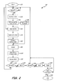
- FIG. 2 is a flow chart of a manufacturing method according to the present invention.
- FIGS. 3A-3C are perspective views of a main body of the cooling baffle being slip fit into a collar.
- the present invention describes a working of components of a vane assembly.
- the present application is applicable to any forming of the product.
- the application is particularly useful to repairs where components of the vane assembly have become worn or degraded during operation of a gas turbine engine. Additionally, articles that result from the working are described.
- the vane assembly is worked according to the following process.
- One or more cooling baffles are cleaned, a collar for each cooling baffle is fabricated and connected to the remainder of the cooling baffle, and the collars and the cooling baffles are installed into the vane assembly.
- the entire vane assembly including the collar, the cooling baffle, and a vane segment that houses the baffle and collar are brazed, inspected, coated, and treated as desired in a concurrent process.
- the method of working is also applicable to a repair where one or more engine operated cooling baffles are removed from the remainder of the vane assembly.
- an engine operated collar of each cooling baffle is destroyed by electric discharge machining.
- the remainder of the cooling baffle is then removed from the remainder of the vane assembly.
- the cooling baffles are cleaned, a replacement collar for each engine operated cooling baffle is fabricated and connected to the remainder of the engine operated cooling baffle, and the replacement collars and the cooling baffles are reinstalled back into the vane assembly.
- the entire vane assembly including the replacement collar, the original cooling baffle, and a vane segment that houses the baffle and collar are brazed, inspected, coated, and treated as desired in a concurrent repair process.
- FIG. 1A is a perspective view of a vane assembly 10 for use in a gas turbine engine.
- FIG. 1B is a sectional view of the vane assembly 10 through one of the airfoils showing the interior thereof.
- the vane assembly 10 includes a vane segment 12 and a cooling baffle 14.
- the vane segment 12 includes airfoils 16, a first platform 18, a second platform 20, a plate 22, and rings 24. Airfoils 16 each have a hollow interior cavity 26.
- the first platform 18 forms an opening 28 to each interior cavity 26.
- the cooling baffle 14 includes a main body 30, a collar 32, cooling orifices 34, and standoffs 36.
- vane assemblies 10 such as those described are known in the art, and are described, for example, in United States Patent Number 7,798,773 .
- the vane segment 12 is arcuate in shape, and several such vane segments 12 can be assembled together within the gas turbine engine to extend around the engine centerline thereof in the compressor or turbine sections.
- the cooling baffles 14 are disposed in and connected to each vane segment 12.
- the cooling baffles 14 extend within the airfoils 16.
- the airfoils 16 extend between and are connected to the first platform 18 and the second platform 20.
- the first platform 18 has an arcuate extent and is disposed radially outward of the arcuate second platform 20.
- the plate 22 and rings 24 are disposed adjacent to the cooling baffles 14.
- the plate 22 extends over the opening 28 in the first platform 18 and connects to the rings 24.
- each ring 24 is disposed adjacent to the top opening of the hollow cooling baffles 14.
- the rings 24 are also connected to the first platform 18 and the plate 22.
- the rings 24 allow cooling airflow to enter the cooling baffle 14 and the vane assembly 10 while the plate 22 provides a seal for the interior cavity 26 of each airfoil 16.
- each cooling baffle 14 is hollow and extends within the hollow interior cavity 26 of each of the airfoils 16.
- the main body 30 of each cooling baffle 14 extends generally radially within the interior cavity 26 to the second platform 20.
- the main body 30 has a cross-sectional area that decreases in size the closer the main body 30 extends toward the second platform 20.
- the collar 32 is positioned on and connected to the outer radial portion of the main body 30 (the portion of the main body 30 that has the largest cross-sectional area).
- the collar 32 is disposed adjacent the ring 24 and has an outer surface that is brazed to the first platform 18 in the opening 28.
- the collar 32 is positioned on and connected to the main body 30 by, for example, a slip fit connection, a light tack weld, adhesives, and/or other connection means. More particularly, a radially inner surface of the collar 32 is then brazed to the main body 30. Thus, the collar 32 is connected to and brazed onto both the main body 30 (the remainder of the cooling baffle 14) and the first platform 18 of the vane segment 12.
- the hollow cooling baffles 14 have cooling orifices 34 therein.
- the standoffs 36 project from the surface of the main body 30 and create space between the cooling baffle 14 and the interior wall of the airfoil 16 to allow a path for airflow therebetween in the interior cavity 26.
- Airflow is supplied to the interior (not shown) of the cooling baffle 14 by a supply duct (not shown) and enters the cooling baffle 14 through the ring 24.
- the cooling air exits the baffle from supply duct 40 situated adjacent a radially inner open end of the cooling baffle 14.
- the airflow is directed through the cooling orifices 34 as it flows through cooling baffle 14. Cooling orifices 34 direct airflow against the interior wall of the airfoil 16.
- a plurality of fins 42 Disposed generally to interface the cooling orifices 34 and extend from the interior wall of the airfoil 16, are a plurality of fins 42.
- the fins 42 form disturbances in the airflow from the cooling orifices 34 to provide better cooling for the airfoil 16.
- the vane assembly 10 shown in FIGS. 1A and 1B is of a type suitable for use in a turbine section of gas turbine engines. Cooling openings (not numbered) are formed in the vane segment 20 to direct a cooling fluid (e.g., bleed air) as desired.
- the airfoils 16 and cooling baffles 14 can be formed of high temperature compatible sheet metal (e.g., from a nickel or cobalt-based superalloy), by stamping and then attached to the first and second platforms 18 and 20 by brazing, welding or other suitable techniques. As will be discussed, treatments and coatings (e.g., thermal barrier coatings) can be applied to surfaces of the vane assembly 10.
- FIG. 2 is a flow chart of a manufacturing method 100 for the engine operated vane assembly 10. From initial start 110, the method 100 proceeds to inspection step 120, which applies if the method comprises a repair. If the method 100 does not apply to a repair method 100 bypasses step 120 and proceeds to step 160.
- step 120 if non-repairable damage is found the vane assembly 10 is scrapped without the working being performed and the method 100 is begun again with a different engine operated vane assembly 10.
- step 120 the method 100 proceeds to step 130 where, if a repair is being performed, the engine operated collar 32 of each engine operated cooling baffle 14 is destroyed. Because the cooling baffles 14 are often welded in place, grinding (e.g., using carbide or oxide burr techniques), electric discharge machining (EDM), or other machining techniques can be used to break existing welds in order to remove the cooling baffles 14 from the vane assembly 10.
- grinding e.g., using carbide or oxide burr techniques
- EDM electric discharge machining
- the destruction of the engine operated collar 32 allows the remainder of each engine operated cooling baffle 14, comprising the main body 30, to be removed from the remainder of the vane assembly 10 (the vane segment 12) in step 140.
- the vane segment 12 is repaired and cleaned at step 150 using known techniques. For example, the vane segment 12 undergoes a braze crack repair and dimension restoration. Additionally, the vane segment 12 is cleaned by, for example, silicone carbide blasting and/or a solvent wipe to remove smut.
- the engine operated cooling baffle 14 (and optionally vane segment 12 if a repair is not being performed) undergoes a clean.
- a collar 44 ( FIGS. 3A-3C ) is fabricated at step 170.
- the collar 44 comprises a replacement part.
- the fabrication of the replacement collar 44 is illustrated as step 170 in the method 100, the fabrication of the collar 44 can occur at any prior point in the method.
- the collar 44 is fabricated by stamping sheet metal to a desired size and shape to connect to and fit on the cooling baffle 14 and the opening 28 in the first platform 18.
- Each collar 44 is connected to the engine operated cooling baffle 14 at step 180.
- the collar 44 is connected to the cooling baffle 14 by slip fitting the baffle 14 into the replacement collar 44.
- the collar 44 is connected to the cooling baffle 14 by a light tack weld between the collar 44 and the cooling baffle 14.
- the collar 44 is connected to the cooling baffle 14 by both slip fitting the cooling baffle 14 into the replacement collar 44 and by tack welding the replacement collar 44 and the cooling baffle 14.
- known forms of creating a connection such as adhesives can be used to connect the collar 44 to the cooling baffle 14.
- step 190 the collar 44 and the cooling baffle 14 are installed into the interior cavity 26 of the vane assembly 10.
- a braze material is applied at step 200 to both a portion of the collar 44 that interfaces with the cooling baffle 14 and to a second portion of the collar 44 that interfaces with the vane assembly 10.
- the braze material is applied to the outer surface of the collar 44 that interfaces with the first platform 18 in the opening 28 ( FIGS. 1A and 1B ).
- step 210 the assembled vane assembly 10, including the cooling baffle 14 and collar 44 are placed in an elevated temperature environment, such as a vacuum furnace, so that the braze material begins to melt.
- inspection of the vane assembly 10 occurs at step 220. Specifically, the coverage of the braze material between the various parts is reviewed to determine if enough braze material has been applied. If the coverage of the braze material is not deemed to be acceptable, the vane assembly 10 is removed from the elevated temperature environment and scrapped. In such an instance, the method 100 would begin again with a different vane assembly 10. If the coverage of the braze material is deemed acceptable the method 100 moves to step 230.
- the assembled vane assembly 10 is bonded. More particularly, the cooling baffle 14, the collar 44, and the vane segment 12 are bonded together using a process such as diffusion bonding. Diffusion bonding is known in the art and is described, for example, in United States Patent Numbers 5,145,105 , 4,250,229 , and 4,010,530 .
- the inspection step 240 can include fluorescent penetrant inspection to determine the existence of cracks in the vane assembly 10.
- Fluorescent penetrant inspection utilizes dyes, powders, and/or fluorescent penetrants to find cracks and other flaws in the surfaces of workpieces. Generally, the penetrant material is infiltrated into the cracks of a workpiece and after the bulk of the material is wiped away, the residual material which is remaining in the crack is sought out optically. Fluorescent penetrant inspection techniques are described in United States Patent Numbers 4,610,157 , 6,427,544 , and 6,683,641 . If unacceptable cracks are discovered the vane assembly 10 is scrapped. In such an instance, the method 100 would begin again with a different vane assembly 10. If the size and/or number of cracks are deemed acceptable the method moves to step 250.
- a coating is applied to the exterior of the vane assembly 10.
- the coating such as an aluminide, protects against corrosion and, in some embodiments, serves as a high temperature thermal barrier.
- the cooling baffle 14 is not coated at step 250, thus the interior cavity 26 ( FIG. 1B ) of each airfoil 16 is masked to prevent the coating from entering.
- the method 100 proceeds from step 250 to step 260 where the vane assembly 10 is heat treated to restore the material properties of the vane assembly 10 components to specification.
- the vane assembly 10 undergoes an airflow inspection at step 270.
- the inspection detemnines if a sufficient amount of airflow (neither too large an amount or too small an amount of airflow) can pass through the vane assembly 10. If the airflow is not as desired the vane assembly 10 is scrapped. In such an instance, the method 100 would begin again with a different engine operated vane assembly 10. If the airflow is acceptable, the method moves to step 280 and the repair is complete. The vane assembly 10 is then ready for reinstallation into the gas turbine engine.
- FIGS. 3A-3C show one embodiment where the collar 44 is connected to and positioned on the engine operated cooling baffle 14.
- the collar 44 is connected to the cooling baffle 14 by fitting the cooling baffle 14 into the collar 44. As shown in FIG. 3A , this is accomplished by positioning the hollow collar 44 below a portion of the cooling baffle 14 with a smaller cross-sectional area (i.e., an inner portion of the main body 30). The cooling baffle 14 is then slipped though the hollow collar 44.
- the upper portion of the main body 30 of the cooling baffle 14 has a slightly larger cross-sectional area than the collar 44.
- an outer surface 47 of the main body 30 and an inner surface 46 of the collar 44 interface and overlap to connect.
- the braze material is applied to the outer surface 47 of the cooling baffle 14 and/or the inner surface 46 of the collar 44 prior to, during, or after the slip fit connection. Additionally, the braze material is applied to an outer surface 48 of the collar 44, which interfaces with the first platform 18 in the opening 28 ( FIG. 1B ). In one embodiment, the brazing of the collar 44 to the cooling baffle 14 and the brazing of the collar 44 to the vane assembly 10 occur simultaneously.
Landscapes
- Engineering & Computer Science (AREA)
- Mechanical Engineering (AREA)
- General Engineering & Computer Science (AREA)
- Turbine Rotor Nozzle Sealing (AREA)
Abstract
A method of working a vane assembly (10) for a gas turbine engine involves a collar (32) and an engine operated cooling baffle (14). The collar is connected to the cooling baffle and installed into the interior cavity (26) of the vane assembly. A braze is applied to both a portion (46) of the collar that interfaces with the cooling baffle and to a second portion (48) of the collar that interfaces with the vane assembly. In one embodiment, the connection between the replacement collar and both the cooling baffle and vane assembly is accomplished by fitting the cooling baffle into the collar and by slipping a portion of the cooling baffle with a smaller cross-sectional area through the collar, and both portions are brazed in the same operation.
Description
- The present invention relates to gas turbine engines, and more particularly to the manufacture and assembly of components of vane assemblies of a gas turbine engine.
- The compressor and turbine sections of gas turbine engines have rotor elements that are separated from one another by vane assemblies. The vane assemblies comprise stator platforms and airfoils that guide the flow of working gases within the turbine and compressor sections. Especially in the turbine section, the temperature of working gases passing through the vane assemblies necessitates that the vane assemblies be cooled by air that is passed through components and features such as film cooling orifices and cooling baffles.
- During operation of the gas turbine engine, the vane assemblies can become worn, damaged, or otherwise degraded such that a repair or replacement is required. In most cases, it is desirable from a regulatory and cost standpoint to repair the vane assemblies rather than replace them.
- Repair of the vane assemblies is generally conducted by first removing the baffles from the vane assembly. The baffles are then machined, cleaned, inspected, and otherwise repaired in a line process that is separate from the repair of the remainder of the vane assembly. Thus, the baffles undergo a separate repair process from the remainder of the vane assembly. After these two separate processes are completed, the baffles are reinserted into the remainder of the vane assembly, and affixed thereto, typically by welding. After being reassembled, the vane assembly then undergoes several additional repair processes.
- Unfortunately, repairing the baffles separately from the vane assembly increases the time required for the repair process and introduces unwanted complexity into the process. The increased time and complexity increases the overall cost of the repair for the vane assemblies making repair a less attractive alternative to replacement.
- A method of working a vane assembly for a gas turbine engine involves a collar and an engine operated cooling baffle. The collar is connected to the cooling baffle and installed into the interior cavity of the vane assembly. A braze is applied to both a portion of the collar that interfaces with the cooling baffle and to a second portion of the collar that interfaces with the vane assembly. In one embodiment, the connection between the replacement collar and both the cooling baffle and vane assembly is accomplished by fitting the cooling baffle into the collar and by slipping a portion of the cooling baffle with a smaller cross-sectional area though the collar.
- In one embodiment, the collar comprises a replacement collar and the cooling baffle comprises an engine operated cooling baffle. An engine operated collar is destroyed by removal from an engine operated cooling baffle, and the engine operated cooling baffle is removed from an interior cavity of the vane assembly. The replacement collar is then connected and brazed to engine operated cooling baffle and vane assembly.
- An assembly for a gas turbine engine includes a vane segment and a cooling baffle. The vane segment has a first platform, a second platform, and one or more airfoils that extend between the first platform and the second platform. Each airfoil has a hollow interior cavity accessible by an opening in the first platform. The cooling baffle extends within the hollow interior of each airfoil. Each cooling baffle includes a collar that is brazed to both a main body of the cooling baffle and to the opening in the first platform.
-
FIG. 1A is a perspective view of a vane assembly. -
FIG. 1B is a sectional view of the vane assembly ofFIG. 1A showing a cooling baffle, an airfoil, and a first and second platforms. -
FIG. 2 is a flow chart of a manufacturing method according to the present invention. -
FIGS. 3A-3C are perspective views of a main body of the cooling baffle being slip fit into a collar. - The present invention describes a working of components of a vane assembly. Thus, the present application is applicable to any forming of the product. However, the application is particularly useful to repairs where components of the vane assembly have become worn or degraded during operation of a gas turbine engine. Additionally, articles that result from the working are described.
- The vane assembly is worked according to the following process. One or more cooling baffles are cleaned, a collar for each cooling baffle is fabricated and connected to the remainder of the cooling baffle, and the collars and the cooling baffles are installed into the vane assembly. Together the entire vane assembly including the collar, the cooling baffle, and a vane segment that houses the baffle and collar are brazed, inspected, coated, and treated as desired in a concurrent process. By brazing, inspecting, coating, and treating the replacement collar, the cooling baffle, and the vane segment simultaneously, the cost and time required for the working is decreased and the complexity of the working is decreased as a single line can be used to repair all components of the vane assembly.
- The method of working is also applicable to a repair where one or more engine operated cooling baffles are removed from the remainder of the vane assembly. To remove the engine operated cooling baffles, an engine operated collar of each cooling baffle is destroyed by electric discharge machining. The remainder of the cooling baffle is then removed from the remainder of the vane assembly. The cooling baffles are cleaned, a replacement collar for each engine operated cooling baffle is fabricated and connected to the remainder of the engine operated cooling baffle, and the replacement collars and the cooling baffles are reinstalled back into the vane assembly. Together the entire vane assembly including the replacement collar, the original cooling baffle, and a vane segment that houses the baffle and collar are brazed, inspected, coated, and treated as desired in a concurrent repair process.
-
FIG. 1A is a perspective view of avane assembly 10 for use in a gas turbine engine.FIG. 1B is a sectional view of thevane assembly 10 through one of the airfoils showing the interior thereof. Thevane assembly 10 includes avane segment 12 and acooling baffle 14. Thevane segment 12 includesairfoils 16, afirst platform 18, asecond platform 20, aplate 22, andrings 24.Airfoils 16 each have a hollowinterior cavity 26. Thefirst platform 18 forms an opening 28 to eachinterior cavity 26. Thecooling baffle 14 includes amain body 30, a collar 32,cooling orifices 34, andstandoffs 36. - The construction and operation of vane assemblies 10 such as those described are known in the art, and are described, for example, in United States Patent Number
7,798,773 . Thevane segment 12 is arcuate in shape, and severalsuch vane segments 12 can be assembled together within the gas turbine engine to extend around the engine centerline thereof in the compressor or turbine sections. - The
cooling baffles 14 are disposed in and connected to eachvane segment 12. In particular, thecooling baffles 14 extend within theairfoils 16. Theairfoils 16 extend between and are connected to thefirst platform 18 and thesecond platform 20. In the embodiment shown, thefirst platform 18 has an arcuate extent and is disposed radially outward of the arcuatesecond platform 20. Theplate 22 and rings 24 are disposed adjacent to the cooling baffles 14. Thus, theplate 22 extends over theopening 28 in thefirst platform 18 and connects to therings 24. In the embodiment shown inFIGS. 1A and 1B , eachring 24 is disposed adjacent to the top opening of the hollow cooling baffles 14. Therings 24 are also connected to thefirst platform 18 and theplate 22. As will be discussed subsequently, therings 24 allow cooling airflow to enter thecooling baffle 14 and thevane assembly 10 while theplate 22 provides a seal for theinterior cavity 26 of eachairfoil 16. - As shown in
FIG. 1B , each coolingbaffle 14 is hollow and extends within the hollowinterior cavity 26 of each of theairfoils 16. Themain body 30 of each coolingbaffle 14 extends generally radially within theinterior cavity 26 to thesecond platform 20. Themain body 30 has a cross-sectional area that decreases in size the closer themain body 30 extends toward thesecond platform 20. The collar 32 is positioned on and connected to the outer radial portion of the main body 30 (the portion of themain body 30 that has the largest cross-sectional area). The collar 32 is disposed adjacent thering 24 and has an outer surface that is brazed to thefirst platform 18 in theopening 28. As will be discussed in further detail subsequently, the collar 32 is positioned on and connected to themain body 30 by, for example, a slip fit connection, a light tack weld, adhesives, and/or other connection means. More particularly, a radially inner surface of the collar 32 is then brazed to themain body 30. Thus, the collar 32 is connected to and brazed onto both the main body 30 (the remainder of the cooling baffle 14) and thefirst platform 18 of thevane segment 12. - The hollow cooling baffles 14 have
cooling orifices 34 therein. Thestandoffs 36 project from the surface of themain body 30 and create space between the coolingbaffle 14 and the interior wall of theairfoil 16 to allow a path for airflow therebetween in theinterior cavity 26. Airflow is supplied to the interior (not shown) of thecooling baffle 14 by a supply duct (not shown) and enters thecooling baffle 14 through thering 24. The cooling air exits the baffle from supply duct 40 situated adjacent a radially inner open end of thecooling baffle 14. The airflow is directed through thecooling orifices 34 as it flows through coolingbaffle 14. Coolingorifices 34 direct airflow against the interior wall of theairfoil 16. Disposed generally to interface thecooling orifices 34 and extend from the interior wall of theairfoil 16, are a plurality offins 42. Thefins 42 form disturbances in the airflow from thecooling orifices 34 to provide better cooling for theairfoil 16. - The
vane assembly 10 shown inFIGS. 1A and 1B is of a type suitable for use in a turbine section of gas turbine engines. Cooling openings (not numbered) are formed in thevane segment 20 to direct a cooling fluid (e.g., bleed air) as desired. Theairfoils 16 and cooling baffles 14 can be formed of high temperature compatible sheet metal (e.g., from a nickel or cobalt-based superalloy), by stamping and then attached to the first andsecond platforms vane assembly 10. -
FIG. 2 is a flow chart of amanufacturing method 100 for the engine operatedvane assembly 10. Frominitial start 110, themethod 100 proceeds toinspection step 120, which applies if the method comprises a repair. If themethod 100 does not apply to arepair method 100 bypasses step 120 and proceeds to step 160. - At
step 120, if non-repairable damage is found thevane assembly 10 is scrapped without the working being performed and themethod 100 is begun again with a different engine operatedvane assembly 10. - After
step 120, themethod 100 proceeds to step 130 where, if a repair is being performed, the engine operated collar 32 of each engine operated coolingbaffle 14 is destroyed. Because the cooling baffles 14 are often welded in place, grinding (e.g., using carbide or oxide burr techniques), electric discharge machining (EDM), or other machining techniques can be used to break existing welds in order to remove the cooling baffles 14 from thevane assembly 10. - The destruction of the engine operated collar 32 allows the remainder of each engine operated cooling
baffle 14, comprising themain body 30, to be removed from the remainder of the vane assembly 10 (the vane segment 12) instep 140. After removal of the engine operated cooling baffles 14, thevane segment 12 is repaired and cleaned atstep 150 using known techniques. For example, thevane segment 12 undergoes a braze crack repair and dimension restoration. Additionally, thevane segment 12 is cleaned by, for example, silicone carbide blasting and/or a solvent wipe to remove smut. - At
step 160, the engine operated cooling baffle 14 (and optionally vanesegment 12 if a repair is not being performed) undergoes a clean. A collar 44 (FIGS. 3A-3C ) is fabricated atstep 170. In the case of a repair, thecollar 44 comprises a replacement part. Although the fabrication of thereplacement collar 44 is illustrated asstep 170 in themethod 100, the fabrication of thecollar 44 can occur at any prior point in the method. In one embodiment, thecollar 44 is fabricated by stamping sheet metal to a desired size and shape to connect to and fit on thecooling baffle 14 and theopening 28 in thefirst platform 18. - Each
collar 44 is connected to the engine operated coolingbaffle 14 atstep 180. In one embodiment, thecollar 44 is connected to thecooling baffle 14 by slip fitting thebaffle 14 into thereplacement collar 44. In another embodiment, thecollar 44 is connected to thecooling baffle 14 by a light tack weld between thecollar 44 and thecooling baffle 14. In yet another embodiment, thecollar 44 is connected to thecooling baffle 14 by both slip fitting thecooling baffle 14 into thereplacement collar 44 and by tack welding thereplacement collar 44 and thecooling baffle 14. In other embodiments, known forms of creating a connection such as adhesives can be used to connect thecollar 44 to thecooling baffle 14. - After connecting the
collar 44 to thecooling baffle 14, themethod 100 proceeds to step 190 where thecollar 44 and thecooling baffle 14 are installed into theinterior cavity 26 of thevane assembly 10. Upon or prior to installation, a braze material is applied atstep 200 to both a portion of thecollar 44 that interfaces with thecooling baffle 14 and to a second portion of thecollar 44 that interfaces with thevane assembly 10. In particular, the braze material is applied to the outer surface of thecollar 44 that interfaces with thefirst platform 18 in the opening 28 (FIGS. 1A and 1B ). - From
step 200, themethod 100 moves to step 210. Atstep 210, the assembledvane assembly 10, including thecooling baffle 14 andcollar 44 are placed in an elevated temperature environment, such as a vacuum furnace, so that the braze material begins to melt. After the braze material begins to melt, inspection of thevane assembly 10 occurs atstep 220. Specifically, the coverage of the braze material between the various parts is reviewed to determine if enough braze material has been applied. If the coverage of the braze material is not deemed to be acceptable, thevane assembly 10 is removed from the elevated temperature environment and scrapped. In such an instance, themethod 100 would begin again with adifferent vane assembly 10. If the coverage of the braze material is deemed acceptable themethod 100 moves to step 230. - At
step 230, the assembledvane assembly 10 is bonded. More particularly, the coolingbaffle 14, thecollar 44, and thevane segment 12 are bonded together using a process such as diffusion bonding. Diffusion bonding is known in the art and is described, for example, in United States Patent Numbers5,145,105 ,4,250,229 , and4,010,530 . - After bonding, the
method 100 moves to aninspection step 240. Theinspection step 240 can include fluorescent penetrant inspection to determine the existence of cracks in thevane assembly 10. Fluorescent penetrant inspection utilizes dyes, powders, and/or fluorescent penetrants to find cracks and other flaws in the surfaces of workpieces. Generally, the penetrant material is infiltrated into the cracks of a workpiece and after the bulk of the material is wiped away, the residual material which is remaining in the crack is sought out optically. Fluorescent penetrant inspection techniques are described in United States Patent Numbers4,610,157 ,6,427,544 , and6,683,641 . If unacceptable cracks are discovered thevane assembly 10 is scrapped. In such an instance, themethod 100 would begin again with adifferent vane assembly 10. If the size and/or number of cracks are deemed acceptable the method moves to step 250. - At
step 250, a coating is applied to the exterior of thevane assembly 10. The coating, such as an aluminide, protects against corrosion and, in some embodiments, serves as a high temperature thermal barrier. The coolingbaffle 14 is not coated atstep 250, thus the interior cavity 26 (FIG. 1B ) of eachairfoil 16 is masked to prevent the coating from entering. Themethod 100 proceeds fromstep 250 to step 260 where thevane assembly 10 is heat treated to restore the material properties of thevane assembly 10 components to specification. - After
step 260, thevane assembly 10 undergoes an airflow inspection atstep 270. The inspection detemnines if a sufficient amount of airflow (neither too large an amount or too small an amount of airflow) can pass through thevane assembly 10. If the airflow is not as desired thevane assembly 10 is scrapped. In such an instance, themethod 100 would begin again with a different engine operatedvane assembly 10. If the airflow is acceptable, the method moves to step 280 and the repair is complete. Thevane assembly 10 is then ready for reinstallation into the gas turbine engine. -
FIGS. 3A-3C show one embodiment where thecollar 44 is connected to and positioned on the engine operated coolingbaffle 14. In particular, as illustrated inFIGS. 3A-3C thecollar 44 is connected to thecooling baffle 14 by fitting thecooling baffle 14 into thecollar 44. As shown inFIG. 3A , this is accomplished by positioning thehollow collar 44 below a portion of thecooling baffle 14 with a smaller cross-sectional area (i.e., an inner portion of the main body 30). The coolingbaffle 14 is then slipped though thehollow collar 44. - As shown in
FIG. 3C , the upper portion of themain body 30 of thecooling baffle 14 has a slightly larger cross-sectional area than thecollar 44. Thus, anouter surface 47 of themain body 30 and aninner surface 46 of thecollar 44 interface and overlap to connect. The braze material is applied to theouter surface 47 of thecooling baffle 14 and/or theinner surface 46 of thecollar 44 prior to, during, or after the slip fit connection. Additionally, the braze material is applied to anouter surface 48 of thecollar 44, which interfaces with thefirst platform 18 in the opening 28 (FIG. 1B ). In one embodiment, the brazing of thecollar 44 to thecooling baffle 14 and the brazing of thecollar 44 to thevane assembly 10 occur simultaneously. - While the invention has been described with reference to an exemplary embodiment(s), it will be understood by those skilled in the art that various changes may be made and equivalents may be substituted for elements thereof without departing from the scope of the invention. In addition, many modifications may be made to adapt a particular situation or material to the teachings of the invention without departing from the essential scope thereof. Therefore, it is intended that the invention not be limited to the particular embodiment(s) disclosed, but that the invention will include all embodiments falling within the scope of the appended claims.
Claims (15)
- A method of forming an assembly for a gas turbine engine, the method comprising:connecting a collar to a cooling baffle;installing the collar and the cooling baffle into an interior cavity of a vane assembly; andapplying a braze to both a first surface of the collar that interfaces with the cooling baffle and to a second surface of the collar that interfaces with the vane assembly.
- The method of claim 1, wherein the cooling baffle comprises an engine operated part and the collar comprises a replacement part.
- The method of claim 1 or 2, further comprising:destroying an engine operated collar of the cooling baffle;removing the cooling baffle from the interior cavity of the vane assembly.
- The method of claim 1, 2 or 3, further comprising:bonding the collar, the cooling baffle, and the vane assembly after brazing;coating exterior surfaces of the vane assembly;heating the cooling baffle and the vane assembly to restore desired material properties; andpassing an airflow through the cooling baffle and the vane assembly.
- The method of claim 4, further comprising inspecting the cooling baffle and the vane assembly after the bonding of the collar, the cooling baffle, and the vane assembly.
- The method of any preceding claim, further comprising:melting the braze joining both the collar to the cooling baffle and the collar to the vane assembly; andinspecting the braze for sufficient coverage after the melting of the braze.
- The method of any preceding claim, wherein the brazing of the collar to the cooling baffle and brazing the collar to the vane assembly occur simultaneously.
- The method of any preceding claim, wherein the collar is connected to the cooling baffle by slip fitting the engine operated baffle into the collar.
- The method of claims 2 and 8 comprising fitting the engine operated cooling baffle into the replacement collar by slipping a portion of the engine operated cooling baffle with a smaller cross-sectional area though the collar.
- The method of any preceding claim, wherein the collar is connected to the cooling baffle by a tack weld between the collar and the cooling baffle.
- The method of claim 3, being a method of repairing a vane assembly for a gas turbine engine.
- The method of claim 11, wherein the both the engine operated cooling baffle and the vane assembly are cleaned separately prior to installation; and optionally comprising the feature of any of claims 2, 4-10.
- An assembly for a gas turbine engine comprising:a vane segment having a first platform, a second platform, and one or more airfoils that extend between the first platform and the second platform, each airfoil having a hollow interior cavity accessible by an opening in the first platform; anda cooling baffle extending within the hollow interior of each airfoil, each cooling baffle including a collar that is brazed to both a main body of the cooling baffle and to the first platform in the opening.
- The assembly of claim 13, wherein the collar is disposed at a radially outward end of the main body of the baffle; and/or
wherein the braze extends along both an inner radial surface of the collar and an outer surface of the collar. - The assembly of claim 13 or 14, wherein a tack weld connects the collar to the main body of the cooling baffle; and/or
wherein the main body of the cooling baffle comprises a repaired part and the collar comprises a newly fabricated part.
Applications Claiming Priority (1)
| Application Number | Priority Date | Filing Date | Title |
|---|---|---|---|
| US13/194,127 US20130025123A1 (en) | 2011-07-29 | 2011-07-29 | Working a vane assembly for a gas turbine engine |
Publications (1)
| Publication Number | Publication Date |
|---|---|
| EP2551457A2 true EP2551457A2 (en) | 2013-01-30 |
Family
ID=46639361
Family Applications (1)
| Application Number | Title | Priority Date | Filing Date |
|---|---|---|---|
| EP12178565A Withdrawn EP2551457A2 (en) | 2011-07-29 | 2012-07-30 | Vane assembly and method of forming a vane assembly for a gas turbine engine |
Country Status (2)
| Country | Link |
|---|---|
| US (1) | US20130025123A1 (en) |
| EP (1) | EP2551457A2 (en) |
Cited By (2)
| Publication number | Priority date | Publication date | Assignee | Title |
|---|---|---|---|---|
| WO2017186481A1 (en) * | 2016-04-27 | 2017-11-02 | Siemens Aktiengesellschaft | Cooling fluid distributor, associated blade, partial insert, and method |
| EP3530882A1 (en) * | 2018-02-26 | 2019-08-28 | MTU Aero Engines GmbH | Method of manufacturing a guide vane segment for a gas turbine and vane segment having a goating |
Families Citing this family (3)
| Publication number | Priority date | Publication date | Assignee | Title |
|---|---|---|---|---|
| US10280793B2 (en) | 2013-09-18 | 2019-05-07 | United Technologies Corporation | Insert and standoff design for a gas turbine engine vane |
| US10024172B2 (en) | 2015-02-27 | 2018-07-17 | United Technologies Corporation | Gas turbine engine airfoil |
| US10801333B2 (en) | 2018-04-17 | 2020-10-13 | Raytheon Technologies Corporation | Airfoils, cores, and methods of manufacture for forming airfoils having fluidly connected platform cooling circuits |
Citations (7)
| Publication number | Priority date | Publication date | Assignee | Title |
|---|---|---|---|---|
| US4010530A (en) | 1975-07-24 | 1977-03-08 | United Technologies Corporation | Method for making blade protective sheaths |
| US4250229A (en) | 1979-04-04 | 1981-02-10 | United Technologies Corporation | Interlayers with amorphous structure for brazing and diffusion bonding |
| US4610157A (en) | 1984-12-11 | 1986-09-09 | United Technologies Corporation | Surface penetrant inspection test piece having varying thickness plating |
| US5145105A (en) | 1986-03-13 | 1992-09-08 | United Technologies Corporation | Diffusion bonding process |
| US6427544B1 (en) | 2001-03-14 | 2002-08-06 | United Technologies Corporation | Environmentally friendly ultra-high sensitivity liquid penetrant inspection process and system |
| US6683641B1 (en) | 1999-09-01 | 2004-01-27 | United Technologies Corporation | Apparatus for inspecting the interior of hollow articles |
| US7798773B2 (en) | 2007-08-06 | 2010-09-21 | United Technologies Corporation | Airfoil replacement repair |
Family Cites Families (2)
| Publication number | Priority date | Publication date | Assignee | Title |
|---|---|---|---|---|
| US5511937A (en) * | 1994-09-30 | 1996-04-30 | Westinghouse Electric Corporation | Gas turbine airfoil with a cooling air regulating seal |
| GB2365932B (en) * | 2000-08-18 | 2004-05-05 | Rolls Royce Plc | Vane assembly |
-
2011
- 2011-07-29 US US13/194,127 patent/US20130025123A1/en not_active Abandoned
-
2012
- 2012-07-30 EP EP12178565A patent/EP2551457A2/en not_active Withdrawn
Patent Citations (7)
| Publication number | Priority date | Publication date | Assignee | Title |
|---|---|---|---|---|
| US4010530A (en) | 1975-07-24 | 1977-03-08 | United Technologies Corporation | Method for making blade protective sheaths |
| US4250229A (en) | 1979-04-04 | 1981-02-10 | United Technologies Corporation | Interlayers with amorphous structure for brazing and diffusion bonding |
| US4610157A (en) | 1984-12-11 | 1986-09-09 | United Technologies Corporation | Surface penetrant inspection test piece having varying thickness plating |
| US5145105A (en) | 1986-03-13 | 1992-09-08 | United Technologies Corporation | Diffusion bonding process |
| US6683641B1 (en) | 1999-09-01 | 2004-01-27 | United Technologies Corporation | Apparatus for inspecting the interior of hollow articles |
| US6427544B1 (en) | 2001-03-14 | 2002-08-06 | United Technologies Corporation | Environmentally friendly ultra-high sensitivity liquid penetrant inspection process and system |
| US7798773B2 (en) | 2007-08-06 | 2010-09-21 | United Technologies Corporation | Airfoil replacement repair |
Cited By (2)
| Publication number | Priority date | Publication date | Assignee | Title |
|---|---|---|---|---|
| WO2017186481A1 (en) * | 2016-04-27 | 2017-11-02 | Siemens Aktiengesellschaft | Cooling fluid distributor, associated blade, partial insert, and method |
| EP3530882A1 (en) * | 2018-02-26 | 2019-08-28 | MTU Aero Engines GmbH | Method of manufacturing a guide vane segment for a gas turbine and vane segment having a goating |
Also Published As
| Publication number | Publication date |
|---|---|
| US20130025123A1 (en) | 2013-01-31 |
Similar Documents
| Publication | Publication Date | Title |
|---|---|---|
| US7798773B2 (en) | Airfoil replacement repair | |
| US8510926B2 (en) | Method for repairing a gas turbine engine component | |
| CA2529337C (en) | Turbine nozzle segment and method of repairing same | |
| CA2448465C (en) | Fabricated repair of cast nozzle | |
| US20080216300A1 (en) | Splitter fairing repair | |
| US8257039B2 (en) | Gas turbine engine case with replaced flange and method of repairing the same using cold metal transfer | |
| US6905308B2 (en) | Turbine nozzle segment and method of repairing same | |
| EP1099508B1 (en) | Turbine nozzle segment and method of repairing same | |
| EP2551457A2 (en) | Vane assembly and method of forming a vane assembly for a gas turbine engine | |
| JP2006037959A (en) | Repair and replacement method of combustor liner panel | |
| US10875131B2 (en) | Repair or remanufacture of blade platform for a gas turbine engine | |
| CA2623675C (en) | Turbine nozzle segment and repair method | |
| JP2013002444A (en) | Method of repairing turbine nozzle segment in turbine engine | |
| US9987708B2 (en) | Automated weld repair of combustor liners | |
| CA2746275C (en) | Turbine nozzle segment and method of repairing same | |
| JP5203362B2 (en) | Repair method for jet engine guide blade segment |
Legal Events
| Date | Code | Title | Description |
|---|---|---|---|
| PUAI | Public reference made under article 153(3) epc to a published international application that has entered the european phase |
Free format text: ORIGINAL CODE: 0009012 |
|
| AK | Designated contracting states |
Kind code of ref document: A2 Designated state(s): AL AT BE BG CH CY CZ DE DK EE ES FI FR GB GR HR HU IE IS IT LI LT LU LV MC MK MT NL NO PL PT RO RS SE SI SK SM TR |
|
| AX | Request for extension of the european patent |
Extension state: BA ME |
|
| STAA | Information on the status of an ep patent application or granted ep patent |
Free format text: STATUS: THE APPLICATION HAS BEEN WITHDRAWN |
|
| 18W | Application withdrawn |
Effective date: 20140724 |