EP3064302A1 - Wire electric discharge machine having function to correct detected value of tensile force - Google Patents
Wire electric discharge machine having function to correct detected value of tensile force Download PDFInfo
- Publication number
- EP3064302A1 EP3064302A1 EP16158750.6A EP16158750A EP3064302A1 EP 3064302 A1 EP3064302 A1 EP 3064302A1 EP 16158750 A EP16158750 A EP 16158750A EP 3064302 A1 EP3064302 A1 EP 3064302A1
- Authority
- EP
- European Patent Office
- Prior art keywords
- tensile force
- detected
- detector
- electric discharge
- wire electrode
- Prior art date
- Legal status (The legal status is an assumption and is not a legal conclusion. Google has not performed a legal analysis and makes no representation as to the accuracy of the status listed.)
- Granted
Links
- 238000003754 machining Methods 0.000 claims description 22
- 230000001939 inductive effect Effects 0.000 claims description 3
- 238000004804 winding Methods 0.000 description 15
- 238000000034 method Methods 0.000 description 13
- 238000010586 diagram Methods 0.000 description 10
- 238000001514 detection method Methods 0.000 description 7
- 238000007796 conventional method Methods 0.000 description 4
- 238000011084 recovery Methods 0.000 description 3
- 238000011144 upstream manufacturing Methods 0.000 description 3
Images


Classifications
-
- B—PERFORMING OPERATIONS; TRANSPORTING
- B23—MACHINE TOOLS; METAL-WORKING NOT OTHERWISE PROVIDED FOR
- B23H—WORKING OF METAL BY THE ACTION OF A HIGH CONCENTRATION OF ELECTRIC CURRENT ON A WORKPIECE USING AN ELECTRODE WHICH TAKES THE PLACE OF A TOOL; SUCH WORKING COMBINED WITH OTHER FORMS OF WORKING OF METAL
- B23H7/00—Processes or apparatus applicable to both electrical discharge machining and electrochemical machining
- B23H7/02—Wire-cutting
- B23H7/04—Apparatus for supplying current to working gap; Electric circuits specially adapted therefor
-
- B—PERFORMING OPERATIONS; TRANSPORTING
- B23—MACHINE TOOLS; METAL-WORKING NOT OTHERWISE PROVIDED FOR
- B23H—WORKING OF METAL BY THE ACTION OF A HIGH CONCENTRATION OF ELECTRIC CURRENT ON A WORKPIECE USING AN ELECTRODE WHICH TAKES THE PLACE OF A TOOL; SUCH WORKING COMBINED WITH OTHER FORMS OF WORKING OF METAL
- B23H11/00—Auxiliary apparatus or details, not otherwise provided for
-
- B—PERFORMING OPERATIONS; TRANSPORTING
- B23—MACHINE TOOLS; METAL-WORKING NOT OTHERWISE PROVIDED FOR
- B23H—WORKING OF METAL BY THE ACTION OF A HIGH CONCENTRATION OF ELECTRIC CURRENT ON A WORKPIECE USING AN ELECTRODE WHICH TAKES THE PLACE OF A TOOL; SUCH WORKING COMBINED WITH OTHER FORMS OF WORKING OF METAL
- B23H7/00—Processes or apparatus applicable to both electrical discharge machining and electrochemical machining
- B23H7/02—Wire-cutting
- B23H7/08—Wire electrodes
- B23H7/10—Supporting, winding or electrical connection of wire-electrode
- B23H7/104—Wire tension control
-
- B—PERFORMING OPERATIONS; TRANSPORTING
- B23—MACHINE TOOLS; METAL-WORKING NOT OTHERWISE PROVIDED FOR
- B23H—WORKING OF METAL BY THE ACTION OF A HIGH CONCENTRATION OF ELECTRIC CURRENT ON A WORKPIECE USING AN ELECTRODE WHICH TAKES THE PLACE OF A TOOL; SUCH WORKING COMBINED WITH OTHER FORMS OF WORKING OF METAL
- B23H7/00—Processes or apparatus applicable to both electrical discharge machining and electrochemical machining
- B23H7/26—Apparatus for moving or positioning electrode relatively to workpiece; Mounting of electrode
- B23H7/265—Mounting of one or more thin electrodes
Definitions
- the present invention relates to a wire electric discharge machine, and more particularly, to a wire electric discharge machine which detects a tensile force of a wire electrode and performs feedback control of the wire electrode.
- an appropriate tensile force is applied to a wire electrode and electric discharge is carried out.
- vibration of the wire electrode is suppressed and precise machining is obtained.
- the tensile force applied to the wire electrode is excessively strong, there is fear that the wire electrode is cut and the machining is interrupted. If the tensile force applied to the wire electrode is excessively weak on the other hand, vibration of the wire electrode cannot be suppressed, and the machining precision is deteriorated.
- a wire electrode is wound around a brake roller connected to an electromagnetic brake, or a wire electrode is pressed against a brake roller by a pinch roller, and voltage applied to the electromagnetic brake is controlled, thereby controlling the tensile force to be applied to the wire electrode, and there is also another method in which rollers for guiding a running state of a wire electrode are placed upstream and downstream of a wire electrode which runs such that the rollers sandwich an electric discharge region, and speed or a torque of a motor which drives the rollers are controlled, thereby controlling a tensile force of the wire electrode.
- Optimal tensile force applied to a wire electrode differs depending upon a wire diameter and a kind of the wire electrode and a kind of machining, and a range of magnitude of the tensile force to be set is wide. However, it is difficult to precisely set a minute or fine difference of the tensile force. Hence, there is used a method in which a tensile force of a wire electrode is measured using a tensile force detector, and the tensile force of the wire electrode is feedback controlled based on the measured tensile force.
- JP 4230157 B1 describes an invention that a brake roller placed upstream of a wire electrode which runs and a lower roller placed downstream of the wire electrode sandwich a machining region, a wire electrode is wound between the brake roller and the lower roller, a tensile force detector for detecting a tensile force of the wire electrode between the brake roller and the lower roller is provided, a speed command is output to a recovery motor which drives a recovery roller placed below the lower roller, thereby controlling the speed of the recovery motor and driving the same, a current command is produced for a brake motor which drives the brake roller based on a tensile force command signal, based on a tensile force detection signal detected by the tensile force detector, based on a speed command to the brake motor, and based on a speed detection signal from a speed detector of the brake motor, and the current command is output to the brake motor to control (torque control) the same, thereby controlling the tensile force of the wire electrode.
- JP 3416514 B1 describes an invention that a take-back motor which takes back a wire electrode is driven at predetermined speed, a speed command for a brake motor is produced based on a tensile force setting signal, a tensile force actually measured value detected by a tensile force detector, and a speed setting signal, and the speed of the brake motor is controlled by the produced speed command, thereby controlling the tensile force of the wire electrode.
- JP 2010-179377 A describes an invention that a tensile force detecting device for detecting a tensile force of a wire electrode which runs in a machining region is provided, and speed or torque of a brake motor which drives a brake roller placed upstream of a running state of the wire electrode, or speed or torque of a sending-out motor for driving a roller which sends out the wire electrode placed downstream of the running state of the wire electrode are controlled such that the tensile force detected by the tensile force detecting device becomes equal to a set tensile force, thereby controlling the tensile force of the wire electrode.
- a method of detecting a tensile force of a wire electrode by a tensile force detector and feedback controlling the tensile force of the wire electrode using the detected tensile force is generally employed.
- the tensile force detector can measure variation in the tensile force by fine resolution, a range where the tensile force can precisely be detected is small. Further, a detected value is varied depending upon a kind of the tensile force detector and depending upon temperature variation, and the tensile force cannot be measured precisely and as a result, there is a problem that a tensile force cannot precisely be controlled.
- thermometer There is a method of calibrating a tensile force detector using a thermometer, but since individual variability exists in the tensile force detectors, it is necessary to perform calibration for every tensile force detector, and there is a problem that the number of operation steps is increased.
- a wire electric discharge machine includes: a tensile force generating unit for giving a tensile force to a wire electrode; and a tensile force detector for detecting a tensile force of the wire electrode, in which a detected tensile force detected by the tensile force detector is fed back to perform feedback control of the tensile force of the wire electrode such that the tensile force becomes equal to a set tensile force, wherein the wire electric discharge machine further includes a calibrating unit which carries out calibration for obtaining a detected deviation amount of the tensile force detector based on the set tensile force and a tensile force detected by the tensile force detector when the set tensile force is applied, the calibrating unit correcting output of the tensile force detector by the detected deviation amount which is obtained by the calibration, and the wire electric discharge machine carries out feedback control of the tensile force of the wire electrode based on a corrected detected tensile force which is obtained
- the detected deviation amount may be obtained and stored as a function of the set tensile force, and when electric discharge machining is carried out, the calibrating unit obtains a detected deviation amount with respect to a value of the tensile force to be set by the function, and the detected tensile force detected by the tensile force detector is corrected with the detected deviation amount, as a corrected detected tensile force.
- sequence of points of a combination of a plurality of set tensile forces and a tensile force detected by the tensile force detector when the set tensile forces are applied may be stored, and when electric discharge machining is carried out, a detected deviation amount with respect to a tensile force which is set when machining is carried out may be obtained by the sequence of points of a combination of the stored set tensile force and the detected tensile force, and the detected tensile force detected by the tensile force detector is corrected with the detected deviation amount, as a corrected detected tensile force.
- the tensile force generating unit may be a motor which applies a driving force to the wire electrode.
- the calibration of the tensile force detector may be carried out when a sending operation of the wire electrode is stopped.
- the calibration of the tensile force detector may be carried out when the wire electrode is sent out.
- the calibration of the tensile force detector may be automatically carried out when temperature is changed by a given amount, or information inducing calibration of the tensile force detector is displayed.
- a deviation amount of a detected tensile force of a tensile force detector is obtained as a function of a set tensile force value, and a detected tensile force value is corrected. Therefore, it is possible to precisely detect a tensile force, and to feedback control a tensile force of a wire electrode and thus, it is possible to enhance the precision of the wire electric discharge machining and to prevent the wire electrode from being cut.
- FIG. 1 is a schematic diagram of an embodiment of the present invention.
- a wire electrode 8 is pulled out from a source bobbin (not shown), the wire electrode 8 passes through an upper wire guide 6 and a lower wire guide 7 while being pressed against a supply roller 4 by a pinch roller 5, and the wire electrode 8 is sandwiched between winding rollers 9 and 9 and is sent out.
- a workpiece W is electric discharge machined between the upper wire guide 6 and the lower wire guide 7.
- the supply roller 4 is driven by a supply motor 12, and the winding rollers 9 are driven by a winding motor 13.
- Driving states of the supply motor 12 and the winding motor 13 are controlled through motor control devices 11 and 14 based on commands from an NC device (numerical controller) 1, and a running state and a tensile force of the wire electrode are controlled.
- the supply roller 4, the pinch roller 5, the supply motor 12, the motor control device 11, the winding rollers 9 and 9, the winding motor 13 and the motor control device 14 configure a tensile force generating unit 10 which gives a tensile force to the wire electrode 8.
- a tensile force detector 2 for detecting a tensile force of the wire electrode 8 in a zone between the supply roller 4 and the winding rollers 9 including an electric discharge machining region.
- the tensile force detector 2 detects a tensile force of the wire electrode 8 and outputs the same to a calibrating unit 3.
- the calibrating unit 3 is a unit for calibrating the tensile force detector 2, and the calibrating unit 3 corrects a tensile force detected by the tensile force detector 2 and outputs the corrected detected tensile force to the NC device 1.
- the NC device 1 controls speed or torque of the supply motor 12 and the winding motor 13 as in the conventional technique based on a command tensile force and the corrected detected tensile force which is input, thereby performing the feedback control such that the tensile force of the wire electrode 8 matches with the command tensile force.
- the present invention is the same as the conventional technique in that a tensile force of a wire electrode is detected using a tensile force detector, and feedback control is performed such that the tensile force of the wire electrode 8 matches with the command tensile force, but the invention is characterized in that the calibrating unit 3 which corrects output of the tensile force detector 2 is added, and a deviation amount of the output of the tensile force detector 2 is corrected.
- the calibrating unit 3 is provided outside the NC device 1 in the embodiment shown in FIG. 1 , the calibrating unit 3 may be provided in the NC device 1 and a processor of the NC device 1 may carry out the operation and the processing as the calibrating unit 3.
- FIGS. 2 to 5 are explanatory diagrams of first to fourth aspects of a calibrating operational principle carried out by the calibrating unit 3, and are explanatory diagrams of a method for obtaining a detected deviation amount between a detected tensile force and an ideal value (actual tensile force) as a function with respect to a set tensile force.
- a detected tensile force y which is output from the tensile force detector 2 is corrected with the detected deviation amount d obtained by a set (command) tensile force x, and the corrected detected tensile force is output. According to this, the detected deviation of the tensile force detector 2 is corrected and a precise tensile force can be detected.
- This first aspect is applied to a tensile force detector in which when the set tensile force (tensile force of wire electrode) x is 0, a detected tensile force y of the tensile force detector 2 is 0, and a detected tensile force y of the tensile force detector 2 is simply proportional to a set tensile force (expected value as actual tensile force, ideal value) x.
- this detected tensile force y is b.
- FIG. 3 is applied to a tensile force detector in which a detected tensile force y is simply proportional to a set tensile force (actual tensile force) x, but a detected tensile force y of the tensile force detector 2 is not 0 when a set tensile force x is 0.
- the set tensile forces x are set to a 1 and a 2 , these tensile forces are applied to the wire electrode 8, respectively, and detected tensile forces y which are output from the tensile force detector 2 are obtained as b 1 and b 2 .
- tensile forces y are detected by the tensile force detector 2 for a plurality of set tensile forces x, and a relational expression f(x) of an approximation straight line is obtained using approximate means such as a least-square method from sequence of points of the detection point (x, y).
- a relational expression f(x) in which these points are connected to one another through a smooth curved line may be obtained.
- a relational expression f(x) of a detected tensile force with respect to the set tensile force may be obtained by controlling speed or torque of the supply motor 12 and the winding motor 13, and by continuously detecting output y of the tensile force detector while continuously changing the tensile force x to be given to the wire electrode.
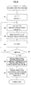
- FIG. 6 is a flowchart showing an algorithm of calibration processing of the tensile force detector carried out by a processor of the calibrating unit 3, or by the processor of the NC device 1 when the calibrating unit is configured in the NC device 1.
- an index n is set to "1"
- a set tensile force value x n which is obtained by adding a predetermined amount a to a last command tensile force value x n-1 is obtained
- the set tensile force value x n is output to the tensile force generating unit 10 (step S2).
- the tensile force generating unit 10 drives and controls the supply motor 12 and the winding motor 13 through the motor control devices 11 and 14 in the same manner as that of the conventional technique, and the wire electrode 8 is made to generate the commanded tensile force x n .
- the wire electrode when the wire electrode is made to generate a tensile force by controlling the speeds of the supply motor 12 and the winding motor 13, speed of the winding roller 9 to wind the wire electrode and speeds of the supply roller 4 and the pinch roller 5 to send out the wire electrode are differentiated from each other, and the wire electrode is made to generate the commanded tensile force x n based on this speed difference.
- the wire electrode When the wire electrode is made to generate a command tensile force by torques of the supply motor 12 and the winding motor 13, a tensile force is generated by controlling the torques of the supply motor 12 and the winding motor 13. In this case, the wire electrode may run or stop running.
- a detected tensile force value y n of output of the tensile force detector 2 is read (step S3), 1 is added to the index n (step S4), it is determined whether the value of the index n is equal to or greater than the number N max which is set for obtaining data (step S5), and if the value of the index n is not equal to or greater than the number N max , the procedure returns to step S2, processing in steps S2 to S5 is executed until the value of the index n reaches the set number N max and thereafter, the procedure is shifted to step S6.
- the number N max for obtained the data is set to "1”
- the relational expression f(x) of the set tensile force x shown in the first expression and the detected tensile force y is obtained by a command tensile force value x 1 (a in FIG. 2 ) and a tensile force detected value y1 (b in FIG. 2 ) which is detected at that time, and a function expression of the set tensile force x which is for obtaining a deviation amount d shown in the second expression is stored.
- the number N max for obtaining the data is set to "2"
- the relational expression f(x) of the set tensile force value x shown in the third expression and the tensile force detected value y is obtained by the commanded set tensile force value x 1 , x 2 (a 1 , a 2 in FIG. 2 ) and the tensile force detected value y 1 , y 2 (b 1 , b 2 in FIG. 2 ) detected at that time, and an expression for obtaining the deviation amount d shown in the expression 4 is stored.
- the relational expression f(x) of the set tensile force value x and the tensile force detected value y is obtained by an approximate method such as a least-square method from sequence of points ((x 1 , y 1 ), (x 2 , y 2 ), ... (xNmax, y Nmax )) which is a combination of commanded set tensile force values x 1 , x 2 ... x Nmax and detected tensile force detected values y 1 , y 2 ... y Nmax .
- an approximate method such as a least-square method from sequence of points ((x 1 , y 1 ), (x 2 , y 2 ), ... (xNmax, y Nmax )) which is a combination of commanded set tensile force values x 1 , x 2 ... x Nmax and detected tensile force detected values y 1 , y 2 ... y Nmax .
- curve approximation is executed from sequence of points ((x 1 , y 1 ), (x 2 , y 2 ) ... (x Nmax , y Nmax )) which is a combination of the set tensile force value and the tensile force detected value, and the relational expression f(x) is obtained.
- FIG. 7 is a flowchart showing an algorithm of processing for obtaining a tensile force value obtained by calibrating and correcting the tensile force detector when the electric discharge machining is carried out.
- the processor of the calibrating unit 3 executes the processing shown in FIG. 7 every predetermined cycle, a tensile force of the wire electrode 8 detected by the tensile force detector 2 is corrected with a detected deviation amount d obtained by calibrating, and a corrected tensile force detected value is obtained.
- a detected tensile force y r which is output of the tensile force detector 2 is read (step T3), a detected tensile force Y r is obtained by subtracting a detected deviation amount (correction amount) d r from the detected tensile force y r (step T4), and the detection processing of a tensile force is completed.
- the NC device 1 drives and controls the tensile force generating unit 10 based on the corrected detected value Y r obtained as described above in the same manner as that of the conventional technique, and feedback control is executed such that a tensile force of the wire electrode 8 matches with the set tensile force value.
- the detected deviation amount (correction amount) d r with respect to the set tensile force value is changed unless this set value is not changed. Therefore, it is possible to employ such a configuration that the processing in steps T1 and T2 is carried out whenever the set value of the tensile force value is changed to obtain the detected deviation amount d r with respect to the set tensile force value, and only the processing in steps T3 and T4 is carried out when detecting a tensile force of the wire electrode.
- the calibration processing of the tensile force detector for obtaining the detected deviation amount d of the tensile force detector as the expression expressing as a function of the set tensile force is carried out based on the command tensile force which is set in the wire electrode and the detected tensile force which is output from the tensile force detector, the detected deviation amount with respect to the set tensile force which is set when the electric discharge machining is carried out is obtained by the function expression of the detected deviation amount, and the output of the tensile force detector is corrected. Therefore, it is possible to easily calibrate the tensile force detector.
- the calibration processing shown in FIG. 6 should be again executed, and a function expression for obtaining a new deviation amount should be obtained.
- the calibration processing may be carried out in a state where the sending operation of the wire electrode is stopped or in a state where the sending operation is not stopped.
- thermometer To facilitate the calibration processing associated with temperature change, it is possible to employ such a configuration that a thermometer is provided, temperature detected by the thermometer is stored in the NC device 1 or the calibrating unit 3 when the calibration processing is carried out, and when temperature is changed from the stored temperature more than a predetermined value, a signal inducing the calibration processing may be output (display on display screen for example). Furthermore, when temperature is changed from the stored temperature more than the predetermined value, the calibration processing shown in FIG. 6 may be executed automatically.
- the relational expression f(x) of the set tensile force x and the tensile force detection y is obtained
- detected tensile force y r is corrected.
Abstract
Description
- The present invention relates to a wire electric discharge machine, and more particularly, to a wire electric discharge machine which detects a tensile force of a wire electrode and performs feedback control of the wire electrode.
- In a wire electric discharge machine, an appropriate tensile force is applied to a wire electrode and electric discharge is carried out. By applying the tensile force to the wire electrode, vibration of the wire electrode is suppressed and precise machining is obtained. However, if the tensile force applied to the wire electrode is excessively strong, there is fear that the wire electrode is cut and the machining is interrupted. If the tensile force applied to the wire electrode is excessively weak on the other hand, vibration of the wire electrode cannot be suppressed, and the machining precision is deteriorated. Hence, it is necessary to apply an appropriate tensile force to the wire electrode during the machining.
- As methods of applying a tensile force to a wire electrode, there is a method in which a wire electrode is wound around a brake roller connected to an electromagnetic brake, or a wire electrode is pressed against a brake roller by a pinch roller, and voltage applied to the electromagnetic brake is controlled, thereby controlling the tensile force to be applied to the wire electrode, and there is also another method in which rollers for guiding a running state of a wire electrode are placed upstream and downstream of a wire electrode which runs such that the rollers sandwich an electric discharge region, and speed or a torque of a motor which drives the rollers are controlled, thereby controlling a tensile force of the wire electrode.
- Optimal tensile force applied to a wire electrode differs depending upon a wire diameter and a kind of the wire electrode and a kind of machining, and a range of magnitude of the tensile force to be set is wide. However, it is difficult to precisely set a minute or fine difference of the tensile force. Hence, there is used a method in which a tensile force of a wire electrode is measured using a tensile force detector, and the tensile force of the wire electrode is feedback controlled based on the measured tensile force.
- For example,
JP 4230157 B1 - Further,
JP 3416514 B1 - Furthermore,
JP 2010-179377 A - A method of detecting a tensile force of a wire electrode by a tensile force detector and feedback controlling the tensile force of the wire electrode using the detected tensile force is generally employed. However, although the tensile force detector can measure variation in the tensile force by fine resolution, a range where the tensile force can precisely be detected is small. Further, a detected value is varied depending upon a kind of the tensile force detector and depending upon temperature variation, and the tensile force cannot be measured precisely and as a result, there is a problem that a tensile force cannot precisely be controlled. There is a method of calibrating a tensile force detector using a thermometer, but since individual variability exists in the tensile force detectors, it is necessary to perform calibration for every tensile force detector, and there is a problem that the number of operation steps is increased.
- Hence, it is an object of the present invention to enhance the precision of wire electric discharge machining and to prevent a wire electrode from being cut.
- A wire electric discharge machine according to the present invention includes: a tensile force generating unit for giving a tensile force to a wire electrode; and a tensile force detector for detecting a tensile force of the wire electrode, in which a detected tensile force detected by the tensile force detector is fed back to perform feedback control of the tensile force of the wire electrode such that the tensile force becomes equal to a set tensile force, wherein the wire electric discharge machine further includes a calibrating unit which carries out calibration for obtaining a detected deviation amount of the tensile force detector based on the set tensile force and a tensile force detected by the tensile force detector when the set tensile force is applied, the calibrating unit correcting output of the tensile force detector by the detected deviation amount which is obtained by the calibration, and the wire electric discharge machine carries out feedback control of the tensile force of the wire electrode based on a corrected detected tensile force which is obtained by correcting the detected tensile force of the tensile force detector by the calibrating unit.
- In the calibration of the calibrating unit, the detected deviation amount may be obtained and stored as a function of the set tensile force, and when electric discharge machining is carried out, the calibrating unit obtains a detected deviation amount with respect to a value of the tensile force to be set by the function, and the detected tensile force detected by the tensile force detector is corrected with the detected deviation amount, as a corrected detected tensile force.
- In the calibration of the calibrating unit, sequence of points of a combination of a plurality of set tensile forces and a tensile force detected by the tensile force detector when the set tensile forces are applied may be stored, and when electric discharge machining is carried out, a detected deviation amount with respect to a tensile force which is set when machining is carried out may be obtained by the sequence of points of a combination of the stored set tensile force and the detected tensile force, and the detected tensile force detected by the tensile force detector is corrected with the detected deviation amount, as a corrected detected tensile force.
- The tensile force generating unit may be a motor which applies a driving force to the wire electrode.
- The calibration of the tensile force detector may be carried out when a sending operation of the wire electrode is stopped.
- The calibration of the tensile force detector may be carried out when the wire electrode is sent out.
- Further, the calibration of the tensile force detector may be automatically carried out when temperature is changed by a given amount, or information inducing calibration of the tensile force detector is displayed.
- According to the present invention, a deviation amount of a detected tensile force of a tensile force detector is obtained as a function of a set tensile force value, and a detected tensile force value is corrected. Therefore, it is possible to precisely detect a tensile force, and to feedback control a tensile force of a wire electrode and thus, it is possible to enhance the precision of the wire electric discharge machining and to prevent the wire electrode from being cut.
- These and other objects and features of the invention will become clear by the following description of a preferred embodiment with reference to the accompanying drawings, wherein:
-
FIG. 1 is a schematic diagram of an embodiment of the present invention; -
FIG. 2 shows a relational expression between a set tensile force and a detected tensile force in the embodiment, and is an explanatory diagram of a first aspect for obtaining a detected deviation amount deviated from an ideal value; -
FIG. 3 shows a relational expression between a set tensile force and a detected tensile force in the embodiment, and is an explanatory diagram of a second aspect for obtaining a detected deviation amount deviated from an ideal value; -
FIG. 4 shows a relational expression between a set tensile force and a detected tensile force in the embodiment, and is an explanatory diagram of a third aspect for obtaining a detected deviation amount deviated from an ideal value; -
FIG. 5 shows a relational expression between a set tensile force and a detected tensile force in the embodiment, and is an explanatory diagram of a fourth aspect for obtaining a detected deviation amount deviated from an ideal value; -
FIG. 6 is a flowchart showing an algorithm of calibration processing for obtaining a detected deviation amount between a detected tensile force and a set tensile force in the embodiment as a function of the set tensile force; and -
FIG. 7 is a flowchart showing an algorithm of processing for obtaining a corrected tensile force value of the embodiment. -
FIG. 1 is a schematic diagram of an embodiment of the present invention. Awire electrode 8 is pulled out from a source bobbin (not shown), thewire electrode 8 passes through anupper wire guide 6 and alower wire guide 7 while being pressed against asupply roller 4 by apinch roller 5, and thewire electrode 8 is sandwiched betweenwinding rollers upper wire guide 6 and thelower wire guide 7. Thesupply roller 4 is driven by asupply motor 12, and thewinding rollers 9 are driven by a windingmotor 13. Driving states of thesupply motor 12 and the windingmotor 13 are controlled throughmotor control devices supply roller 4, thepinch roller 5, thesupply motor 12, themotor control device 11, thewinding rollers motor 13 and themotor control device 14 configure a tensileforce generating unit 10 which gives a tensile force to thewire electrode 8. - There is provided a
tensile force detector 2 for detecting a tensile force of thewire electrode 8 in a zone between thesupply roller 4 and thewinding rollers 9 including an electric discharge machining region. Thetensile force detector 2 detects a tensile force of thewire electrode 8 and outputs the same to a calibratingunit 3. The calibratingunit 3 is a unit for calibrating thetensile force detector 2, and the calibratingunit 3 corrects a tensile force detected by thetensile force detector 2 and outputs the corrected detected tensile force to theNC device 1. TheNC device 1 controls speed or torque of thesupply motor 12 and thewinding motor 13 as in the conventional technique based on a command tensile force and the corrected detected tensile force which is input, thereby performing the feedback control such that the tensile force of thewire electrode 8 matches with the command tensile force. - The present invention is the same as the conventional technique in that a tensile force of a wire electrode is detected using a tensile force detector, and feedback control is performed such that the tensile force of the
wire electrode 8 matches with the command tensile force, but the invention is characterized in that thecalibrating unit 3 which corrects output of thetensile force detector 2 is added, and a deviation amount of the output of thetensile force detector 2 is corrected. - Although the
calibrating unit 3 is provided outside theNC device 1 in the embodiment shown inFIG. 1 , thecalibrating unit 3 may be provided in theNC device 1 and a processor of theNC device 1 may carry out the operation and the processing as thecalibrating unit 3. -
FIGS. 2 to 5 are explanatory diagrams of first to fourth aspects of a calibrating operational principle carried out by the calibratingunit 3, and are explanatory diagrams of a method for obtaining a detected deviation amount between a detected tensile force and an ideal value (actual tensile force) as a function with respect to a set tensile force. - The tensile
force generating unit 10 gives a set tensile force x to thewire electrode 8, and detects (detected value y) a tensile force by thetensile force detector 2. This operation is carried out for one or more set tensile forces x. From obtained sequence of points, it is possible to obtain relational expression y=f(x) using a tensile force y detected by thetensile force detector 2 as a function of the set tensile force x. When the set tensile force x is given to thewire electrode 8, the tensile force of the wire electrode is x. As a detected tensile force y which is output from thetensile force detector 2, a fact that y=x is an expected value, and this is the ideal value. Hence, a detected deviation amount d that is a detected deviation amount from the ideal value of the detected tensile force value which is output from thetensile force detector 2 is obtained as d=f(x)-x. - When the electric discharge machining is carried out, a detected tensile force y which is output from the
tensile force detector 2 is corrected with the detected deviation amount d obtained by a set (command) tensile force x, and the corrected detected tensile force is output. According to this, the detected deviation of thetensile force detector 2 is corrected and a precise tensile force can be detected. -
FIG. 2 is an explanatory diagram of the first aspect of the method in which a set tensile force x is one point, a relational expression y=f(x) of the set tensile force and the detected value is obtained by the tensile force y detected by thetensile force detector 2 at that time, and a detected deviation amount d is obtained. This first aspect is applied to a tensile force detector in which when the set tensile force (tensile force of wire electrode) x is 0, a detected tensile force y of thetensile force detector 2 is 0, and a detected tensile force y of thetensile force detector 2 is simply proportional to a set tensile force (expected value as actual tensile force, ideal value) x. - The tensile
force generating unit 10 is driven, speed and torque of thesupply motor 12 and the windingmotor 13 are controlled, a set tensile force x=a is given to the wire electrode, and thetensile force detector 2 detects a tensile force. Suppose that this detected tensile force y is b. - Then, a relational expression f(x) between the set tensile force x and the detected tensile force y becomes


-
FIG. 3 is applied to a tensile force detector in which a detected tensile force y is simply proportional to a set tensile force (actual tensile force) x, but a detected tensile force y of thetensile force detector 2 is not 0 when a set tensile force x is 0. In this case, the set tensile forces x are set to a1 and a2, these tensile forces are applied to thewire electrode 8, respectively, and detected tensile forces y which are output from thetensile force detector 2 are obtained as b1 and b2. According to this, expression f(x) of the detected tensile force y expressed as a function of the set tensile force x becomes

-
FIG. 4 is an explanatory diagram of a third aspect of obtaining a relational expression y=f(x) of a tensile force y detected by thetensile force detector 2 expressed as a function of a set tensile force x. In this third aspect, tensile forces y are detected by thetensile force detector 2 for a plurality of set tensile forces x, and a relational expression f(x) of an approximation straight line is obtained using approximate means such as a least-square method from sequence of points of the detection point (x, y). - Further, as shown in
FIG. 5 , a relational expression f(x) in which these points are connected to one another through a smooth curved line may be obtained. The detected deviation amount d is obtained as a function of a set tensile force x by d=f(x)-x. - A relational expression f(x) of a detected tensile force with respect to the set tensile force may be obtained by controlling speed or torque of the
supply motor 12 and the windingmotor 13, and by continuously detecting output y of the tensile force detector while continuously changing the tensile force x to be given to the wire electrode. -
FIG. 6 is a flowchart showing an algorithm of calibration processing of the tensile force detector carried out by a processor of the calibratingunit 3, or by the processor of theNC device 1 when the calibrating unit is configured in theNC device 1. - If a calibration command of the
tensile force detector 2 is input to theNC device 1, the processor which executes the calibration processing starts the processing shown inFIG. 6 . - First, an index n is set to "1", an initial tensile force value x0=xn-1 is set to "0" (step S1), a set tensile force value xn which is obtained by adding a predetermined amount a to a last command tensile force value xn-1 is obtained, and the set tensile force value xn is output to the tensile force generating unit 10 (step S2). The tensile
force generating unit 10 drives and controls thesupply motor 12 and the windingmotor 13 through themotor control devices wire electrode 8 is made to generate the commanded tensile force xn. That is, when the wire electrode is made to generate a tensile force by controlling the speeds of thesupply motor 12 and the windingmotor 13, speed of the windingroller 9 to wind the wire electrode and speeds of thesupply roller 4 and thepinch roller 5 to send out the wire electrode are differentiated from each other, and the wire electrode is made to generate the commanded tensile force xn based on this speed difference. When the wire electrode is made to generate a command tensile force by torques of thesupply motor 12 and the windingmotor 13, a tensile force is generated by controlling the torques of thesupply motor 12 and the windingmotor 13. In this case, the wire electrode may run or stop running. - Next, a detected tensile force value yn of output of the
tensile force detector 2 is read (step S3), 1 is added to the index n (step S4), it is determined whether the value of the index n is equal to or greater than the number Nmax which is set for obtaining data (step S5), and if the value of the index n is not equal to or greater than the number Nmax, the procedure returns to step S2, processing in steps S2 to S5 is executed until the value of the index n reaches the set number Nmax and thereafter, the procedure is shifted to step S6. A relational expression f(x) which expresses tensile force detection y by a function of the set tensile force x from commanded set tensile force values x1 to xNmax and detected tensile force values y1 to yNmax of output of the tensile force detector is obtained (step S6), a function expression d=f(x)-x which expresses a detected deviation amount d for calibrating thetensile force detector 2 by a function of the set tensile force x is obtained and stored (step S7), and the calibration processing is completed. - For obtaining the relational expression f(x) by the first aspect shown in
FIG. 2 , the number Nmax for obtained the data is set to "1", the relational expression f(x) of the set tensile force x shown in the first expression and the detected tensile force y is obtained by a command tensile force value x1 (a inFIG. 2 ) and a tensile force detected value y1 (b inFIG. 2 ) which is detected at that time, and a function expression of the set tensile force x which is for obtaining a deviation amount d shown in the second expression is stored.
- For obtaining the relational expression f(x) by the second aspect shown in
FIG. 3 , the number Nmax for obtaining the data is set to "2", the relational expression f(x) of the set tensile force value x shown in the third expression and the tensile force detected value y is obtained by the commanded set tensile force value x1, x2 (a1, a2 inFIG. 2 ) and the tensile force detected value y1, y2 (b1, b2 inFIG. 2 ) detected at that time, and an expression for obtaining the deviation amount d shown in theexpression 4 is stored.
- For obtaining the relational expression f(x) by the third aspect shown in
FIG. 4 , the relational expression f(x) of the set tensile force value x and the tensile force detected value y is obtained by an approximate method such as a least-square method from sequence of points ((x1, y1), (x2, y2), ... (xNmax, yNmax)) which is a combination of commanded set tensile force values x1, x2 ... xNmax and detected tensile force detected values y1, y2 ... yNmax. For obtaining the relational expression f(x) by the fourth aspect shown inFIG. 5 , curve approximation is executed from sequence of points ((x1, y1), (x2, y2) ... (xNmax, yNmax)) which is a combination of the set tensile force value and the tensile force detected value, and the relational expression f(x) is obtained. A relational expression d=f(x)-x for obtaining the detected deviation amount d to calibrate thetensile force detector 2 by the relational expression f(x) obtained in the above-described manner is obtained and stored. -
FIG. 7 is a flowchart showing an algorithm of processing for obtaining a tensile force value obtained by calibrating and correcting the tensile force detector when the electric discharge machining is carried out. - When the electric discharge machining is carried out, the processor of the calibrating unit 3 (including calibrating unit provided in NC device 1) executes the processing shown in
FIG. 7 every predetermined cycle, a tensile force of thewire electrode 8 detected by thetensile force detector 2 is corrected with a detected deviation amount d obtained by calibrating, and a corrected tensile force detected value is obtained. - First, a commanded set tensile force value xr is read (step T1), and a detected deviation amount (correction amount) dr with respect to this set tensile force value xr is obtained by a function expression d=f(x)-x of the set tensile force x which is for obtaining the detected deviation amount d obtained by the calibration processing (step T2).
- Next, a detected tensile force yr which is output of the
tensile force detector 2 is read (step T3), a detected tensile force Yr is obtained by subtracting a detected deviation amount (correction amount) dr from the detected tensile force yr (step T4), and the detection processing of a tensile force is completed. - The
NC device 1 drives and controls the tensileforce generating unit 10 based on the corrected detected value Yr obtained as described above in the same manner as that of the conventional technique, and feedback control is executed such that a tensile force of thewire electrode 8 matches with the set tensile force value. - After the tensile force value is set, the detected deviation amount (correction amount) dr with respect to the set tensile force value is changed unless this set value is not changed. Therefore, it is possible to employ such a configuration that the processing in steps T1 and T2 is carried out whenever the set value of the tensile force value is changed to obtain the detected deviation amount dr with respect to the set tensile force value, and only the processing in steps T3 and T4 is carried out when detecting a tensile force of the wire electrode.
- As described above, according to the present invention, the calibration processing of the tensile force detector for obtaining the detected deviation amount d of the tensile force detector as the expression expressing as a function of the set tensile force is carried out based on the command tensile force which is set in the wire electrode and the detected tensile force which is output from the tensile force detector, the detected deviation amount with respect to the set tensile force which is set when the electric discharge machining is carried out is obtained by the function expression of the detected deviation amount, and the output of the tensile force detector is corrected. Therefore, it is possible to easily calibrate the tensile force detector. Further, even if the tensile force detector is once calibrated, there is a possibility that the detected tensile force of the tensile force detector is deviated (detected deviation amount is changed) if temperature is changed. Hence, when temperature is changed more than the difference which is set during the machining, it should be determined that the detected value of the tensile force detector is deviated, the calibration processing shown in
FIG. 6 should be again executed, and a function expression for obtaining a new deviation amount should be obtained. In this case, the calibration processing may be carried out in a state where the sending operation of the wire electrode is stopped or in a state where the sending operation is not stopped. To facilitate the calibration processing associated with temperature change, it is possible to employ such a configuration that a thermometer is provided, temperature detected by the thermometer is stored in theNC device 1 or thecalibrating unit 3 when the calibration processing is carried out, and when temperature is changed from the stored temperature more than a predetermined value, a signal inducing the calibration processing may be output (display on display screen for example). Furthermore, when temperature is changed from the stored temperature more than the predetermined value, the calibration processing shown inFIG. 6 may be executed automatically. - In the above-described embodiment, the relational expression f(x) of the set tensile force x and the tensile force detection y is obtained, the function expression d=f(x)-x of the detected deviation amount is obtained from the relational expression f(x) and is stored, and when the electric discharge machining is carried out, the detected deviation amount dr with respect to the set tensile force xr is obtained from the function expression d=f(x)-x of the detected deviation amount, and detected tensile force yr is corrected. Alternatively, it is possible to employ such a configuration that the relational expression f(x) is obtained, sequence of points (x1, y1), (x2, y2) ... (xn, yn) which is a combination of the tensile force detections y which are detected for the plurality of set tensile forces x and the plurality of set tensile forces x is stored instead of the relational expression f(x) at the time of calibration of the
tensile force detector 2 without storing the function expression d=f(x)-x of the detected deviation amount, and the detected deviation amount dr for calibrating the set tensile force value xr is obtained from the stored sequence of points. That is, among the sequence of points to be stored, interpolation is executed from two points of the set tensile force values before and after the set tensile force value, and corrected detected tensile force Yr is obtained. - Although the embodiment of the present invention has been described above, the invention is not limited to the embodiment, and the invention can be carried out in other aspects by appropriately changing the embodiment.
Claims (7)
- A wire electric discharge machine comprising:a tensile force generating unit for giving a tensile force to a wire electrode; anda tensile force detector for detecting a tensile force of the wire electrode, in which a detected tensile force detected by the tensile force detector is fed back to perform feedback control of the tensile force of the wire electrode such that the tensile force becomes equal to a set tensile force, whereinthe wire electric discharge machine further includes a calibrating unit which carries out calibration for obtaining a detected deviation amount of the tensile force detector based on the set tensile force and a tensile force detected by the tensile force detector when the set tensile force is applied, the calibrating unit correcting output of the tensile force detector by the detected deviation amount which is obtained by the calibration, andthe wire electric discharge machine has a function to correct a detected value of a tensile force for carrying out feedback control of the tensile force of the wire electrode based on a corrected detected tensile force which is obtained by correcting the detected tensile force of the tensile force detector by the calibrating unit.
- The wire electric discharge machine having a function to correct a detected value of a tensile force according to claim 1, wherein in the calibration of the calibrating unit, the detected deviation amount is obtained and stored as a function of the set tensile force, and when electric discharge machining is carried out, the calibrating unit obtains a detected deviation amount with respect to a value of the tensile force to be set by the function, and the detected tensile force detected by the tensile force detector is corrected with the detected deviation amount, as a corrected detected tensile force.
- The wire electric discharge machine having a function to correct a detected value of a tensile force according to claim 1, wherein in the calibration of the calibrating unit, sequence of points of a combination of a plurality of set tensile forces and a tensile force detected by the tensile force detector when the set tensile forces are applied is stored, and when electric discharge machining is carried out, a detected deviation amount with respect to a tensile force which is set when machining is carried out is obtained by the sequence of points of a combination of the stored set tensile force and the detected tensile force, and the detected tensile force detected by the tensile force detector is corrected with the detected deviation amount, as a corrected detected tensile force.
- The wire electric discharge machine having a function to correct a detected value of a tensile force according to any one of claims 1 to 3, wherein the tensile force generating unit is a motor which applies a driving force to the wire electrode.
- The wire electric discharge machine having a function to correct a detected value of a tensile force according to any one of claims 1 to 4, wherein the calibration of the tensile force detector is carried out when a sending operation of the wire electrode is stopped.
- The wire electric discharge machine having a function to correct a detected value of a tensile force according to any one of claims 1 to 4, wherein the calibration of the tensile force detector is carried out when the wire electrode is sent out.
- The wire electric discharge machine having a function to correct a detected value of a tensile force according to any one of claims 1 to 6, wherein the calibration of the tensile force detector is automatically carried out when temperature is changed by a given amount, or information inducing calibration of the tensile force detector is displayed.
Applications Claiming Priority (1)
| Application Number | Priority Date | Filing Date | Title |
|---|---|---|---|
| JP2015044991A JP6133917B2 (en) | 2015-03-06 | 2015-03-06 | Wire electric discharge machine having a function of correcting the detected tension value |
Publications (2)
| Publication Number | Publication Date |
|---|---|
| EP3064302A1 true EP3064302A1 (en) | 2016-09-07 |
| EP3064302B1 EP3064302B1 (en) | 2020-04-22 |
Family
ID=55456717
Family Applications (1)
| Application Number | Title | Priority Date | Filing Date |
|---|---|---|---|
| EP16158750.6A Active EP3064302B1 (en) | 2015-03-06 | 2016-03-04 | Wire electric discharge machine having function to correct detected value of tensile force |
Country Status (5)
| Country | Link |
|---|---|
| US (1) | US10105776B2 (en) |
| EP (1) | EP3064302B1 (en) |
| JP (1) | JP6133917B2 (en) |
| KR (1) | KR101904598B1 (en) |
| CN (1) | CN105935821B (en) |
Cited By (1)
| Publication number | Priority date | Publication date | Assignee | Title |
|---|---|---|---|---|
| CN114414142A (en) * | 2022-01-25 | 2022-04-29 | 苏州汇川控制技术有限公司 | Calibration method and device for tension sensor, calibration equipment and medium |
Families Citing this family (5)
| Publication number | Priority date | Publication date | Assignee | Title |
|---|---|---|---|---|
| JP6444959B2 (en) * | 2016-11-01 | 2018-12-26 | ファナック株式会社 | Wire electric discharge machine |
| DE112017000226B4 (en) | 2016-11-10 | 2024-04-18 | Seibu Electric & Machinery Co., Ltd. | Voltage control method and electrical discharge processing device |
| KR102025770B1 (en) | 2019-03-15 | 2019-09-26 | 변영일 | Menufacturing device for cutting tools using wire electric discharge machining |
| CN109967809B (en) * | 2019-04-09 | 2020-12-11 | 南京航空航天大学 | Wire cut electrical discharge machining electrode wire tension detection and LCD image display device |
| JP7451191B2 (en) * | 2020-01-28 | 2024-03-18 | 住友重機械工業株式会社 | Controls and roll-to-roll conveying systems |
Citations (6)
| Publication number | Priority date | Publication date | Assignee | Title |
|---|---|---|---|---|
| JPS63256316A (en) * | 1987-04-13 | 1988-10-24 | Mitsubishi Electric Corp | Wire electric discharge machining device |
| JP3416514B2 (en) | 1997-03-07 | 2003-06-16 | 株式会社ソディック | Wire electrode tension control method and device in wire electric discharge machine |
| JP4230157B2 (en) | 2002-03-19 | 2009-02-25 | 三菱電機株式会社 | Wire tension control device for wire electric discharge machine |
| JP2010179377A (en) | 2009-02-03 | 2010-08-19 | Fanuc Ltd | Wire-cut electric-discharging apparatus with residual quantity detecting function of wire electrode |
| WO2014068679A1 (en) * | 2012-10-30 | 2014-05-08 | 三菱電機株式会社 | Wire electrical discharge machining device, machining control device and machining control program |
| US20140291295A1 (en) * | 2013-04-02 | 2014-10-02 | Fanuc Corporation | Wire electric discharge machine having wire electrode tension control function |
Family Cites Families (22)
| Publication number | Priority date | Publication date | Assignee | Title |
|---|---|---|---|---|
| CH620620A5 (en) * | 1978-05-29 | 1980-12-15 | Charmilles Sa Ateliers | |
| JPS59152022A (en) * | 1983-02-15 | 1984-08-30 | Fanuc Ltd | Method for controlling wire electrode tension |
| JPS59152021A (en) * | 1983-02-15 | 1984-08-30 | Fanuc Ltd | Wire cut electric discharge machining equipment |
| JPS60177824A (en) * | 1984-02-21 | 1985-09-11 | Inoue Japax Res Inc | Wire electrode decision apparatus |
| JPS63127830A (en) * | 1986-11-17 | 1988-05-31 | Hoden Seimitsu Kako Kenkyusho Ltd | Wire electric discharge machine |
| JPH01199726A (en) * | 1988-02-03 | 1989-08-11 | Fanuc Ltd | Device for detecting and controlling wire tension and breaking of wire |
| JP2692386B2 (en) * | 1991-01-17 | 1997-12-17 | 三菱電機株式会社 | Wire electric discharge machine |
| JPH05312657A (en) * | 1992-05-08 | 1993-11-22 | I N R Kenkyusho:Kk | Wire tension measuring device |
| JPH07328849A (en) * | 1994-06-13 | 1995-12-19 | Okuma Mach Works Ltd | Control method for tensile force and feed speed of wire electrode and device therefor |
| EP0916440B1 (en) * | 1997-03-07 | 2006-05-10 | Sodick Co., Ltd. | System and method for wire cut discharge machining |
| JP3883690B2 (en) * | 1998-03-04 | 2007-02-21 | 株式会社ソディック | Wire electrode tension control device and method for wire electric discharge machine, and determination and adjustment setting method for filter of tension control circuit |
| JP3696431B2 (en) * | 1999-04-08 | 2005-09-21 | 株式会社ミツトヨ | One-dimensional measuring machine |
| JP2002340711A (en) * | 2001-05-18 | 2002-11-27 | Mitsubishi Electric Corp | Wire electrode tension sensor and wire discharge machine |
| JP2002346840A (en) * | 2001-05-29 | 2002-12-04 | Hitachi Via Mechanics Ltd | Wire electric discharge machining apparatus |
| JP4463534B2 (en) * | 2003-12-02 | 2010-05-19 | 住友重機械工業株式会社 | Molding apparatus, molded product and mold relative distance measuring method |
| JP4168076B2 (en) | 2007-03-08 | 2008-10-22 | ファナック株式会社 | Wire cut electric discharge machine with wire electrode tension control function |
| JP2009180523A (en) * | 2008-01-29 | 2009-08-13 | Toshiba Corp | Angle detection apparatus and method for acquiring angle correction curve of the same |
| CN101670472B (en) * | 2008-09-12 | 2011-06-08 | 财团法人工业技术研究院 | Method and device for controlling wire cutting electrochemical discharge processing and feeding |
| WO2011067877A1 (en) | 2009-12-01 | 2011-06-09 | 株式会社フジキン | Pressure-type flow rate control device |
| JP5088975B2 (en) | 2010-10-19 | 2012-12-05 | 株式会社ソディック | Wire electrical discharge machine |
| JP2014028463A (en) * | 2012-07-31 | 2014-02-13 | Ricoh Co Ltd | Image forming apparatus, pattern position detection method, image formation system, and method for producing printed matter |
| CN203254023U (en) * | 2013-01-30 | 2013-10-30 | 南通伊阳精密机械有限公司 | Tension adjustable devices of linear cutting machine |
-
2015
- 2015-03-06 JP JP2015044991A patent/JP6133917B2/en active Active
-
2016
- 2016-03-03 KR KR1020160025879A patent/KR101904598B1/en active IP Right Grant
- 2016-03-04 CN CN201610124944.9A patent/CN105935821B/en active Active
- 2016-03-04 EP EP16158750.6A patent/EP3064302B1/en active Active
- 2016-03-05 US US15/062,106 patent/US10105776B2/en active Active
Patent Citations (7)
| Publication number | Priority date | Publication date | Assignee | Title |
|---|---|---|---|---|
| JPS63256316A (en) * | 1987-04-13 | 1988-10-24 | Mitsubishi Electric Corp | Wire electric discharge machining device |
| JP3416514B2 (en) | 1997-03-07 | 2003-06-16 | 株式会社ソディック | Wire electrode tension control method and device in wire electric discharge machine |
| JP4230157B2 (en) | 2002-03-19 | 2009-02-25 | 三菱電機株式会社 | Wire tension control device for wire electric discharge machine |
| JP2010179377A (en) | 2009-02-03 | 2010-08-19 | Fanuc Ltd | Wire-cut electric-discharging apparatus with residual quantity detecting function of wire electrode |
| WO2014068679A1 (en) * | 2012-10-30 | 2014-05-08 | 三菱電機株式会社 | Wire electrical discharge machining device, machining control device and machining control program |
| US20150290733A1 (en) * | 2012-10-30 | 2015-10-15 | Mitsubishi Electric Corporation | Wire electrical discharge machining apparatus, machining control device, and machining control program |
| US20140291295A1 (en) * | 2013-04-02 | 2014-10-02 | Fanuc Corporation | Wire electric discharge machine having wire electrode tension control function |
Cited By (1)
| Publication number | Priority date | Publication date | Assignee | Title |
|---|---|---|---|---|
| CN114414142A (en) * | 2022-01-25 | 2022-04-29 | 苏州汇川控制技术有限公司 | Calibration method and device for tension sensor, calibration equipment and medium |
Also Published As
| Publication number | Publication date |
|---|---|
| EP3064302B1 (en) | 2020-04-22 |
| KR101904598B1 (en) | 2018-10-04 |
| CN105935821B (en) | 2018-11-02 |
| CN105935821A (en) | 2016-09-14 |
| JP2016163923A (en) | 2016-09-08 |
| US20160263690A1 (en) | 2016-09-15 |
| US10105776B2 (en) | 2018-10-23 |
| KR20160108209A (en) | 2016-09-19 |
| JP6133917B2 (en) | 2017-05-24 |
Similar Documents
| Publication | Publication Date | Title |
|---|---|---|
| EP3064302B1 (en) | Wire electric discharge machine having function to correct detected value of tensile force | |
| US10259118B2 (en) | Robot system having function of simplifying teaching operation and improving operating performance by learning | |
| US9829877B2 (en) | Servo control apparatus having function of displaying adjustment state in online automatic adjustment to control system | |
| US10029873B2 (en) | Apparatus for controlling conveyance between rollers | |
| JP5889497B1 (en) | Roller transfer control device | |
| US10254741B2 (en) | Robot apparatus having learning function | |
| US8836528B2 (en) | Data display device for machine tool for displaying information based on specified condition | |
| US10023416B2 (en) | Inter-roller conveyance control device | |
| TW201221457A (en) | Method and arrangement in connection with winder drive | |
| JP2008174355A (en) | Tension control device and tension control method | |
| JP2013216450A (en) | Control device and control method for unwind roll | |
| WO2018087986A1 (en) | Tension-controlling method and electric discharge machining apparatus | |
| JP6428669B2 (en) | Polling reel speed control device | |
| EP2822176B1 (en) | Vector control apparatus of induction motor | |
| JP5845853B2 (en) | Metal strip break detection system and break detection method | |
| WO2018193649A1 (en) | Electric motor control device | |
| JPH061533A (en) | Tension control device of winding/unwinding machine | |
| JP6189695B2 (en) | Wire feeder | |
| WO2018158828A1 (en) | Mathematical model calculation apparatus for seat material production line, and control apparatus | |
| JPH06261574A (en) | Control device of servomotor | |
| JPH09323851A (en) | Winder | |
| JP2014204565A (en) | Motor drive unit and motor drive method | |
| JPH09278240A (en) | Initial diameter finding method for winding in/out roll and device thereof | |
| JPH0342108A (en) | Learning method for starting point of control for tube end in reducing mill | |
| JPH02215642A (en) | Rounding reference generating method |
Legal Events
| Date | Code | Title | Description |
|---|---|---|---|
| PUAI | Public reference made under article 153(3) epc to a published international application that has entered the european phase |
Free format text: ORIGINAL CODE: 0009012 |
|
| AK | Designated contracting states |
Kind code of ref document: A1 Designated state(s): AL AT BE BG CH CY CZ DE DK EE ES FI FR GB GR HR HU IE IS IT LI LT LU LV MC MK MT NL NO PL PT RO RS SE SI SK SM TR |
|
| AX | Request for extension of the european patent |
Extension state: BA ME |
|
| STAA | Information on the status of an ep patent application or granted ep patent |
Free format text: STATUS: REQUEST FOR EXAMINATION WAS MADE |
|
| 17P | Request for examination filed |
Effective date: 20170306 |
|
| RBV | Designated contracting states (corrected) |
Designated state(s): AL AT BE BG CH CY CZ DE DK EE ES FI FR GB GR HR HU IE IS IT LI LT LU LV MC MK MT NL NO PL PT RO RS SE SI SK SM TR |
|
| GRAP | Despatch of communication of intention to grant a patent |
Free format text: ORIGINAL CODE: EPIDOSNIGR1 |
|
| STAA | Information on the status of an ep patent application or granted ep patent |
Free format text: STATUS: GRANT OF PATENT IS INTENDED |
|
| INTG | Intention to grant announced |
Effective date: 20200115 |
|
| GRAS | Grant fee paid |
Free format text: ORIGINAL CODE: EPIDOSNIGR3 |
|
| GRAA | (expected) grant |
Free format text: ORIGINAL CODE: 0009210 |
|
| STAA | Information on the status of an ep patent application or granted ep patent |
Free format text: STATUS: THE PATENT HAS BEEN GRANTED |
|
| AK | Designated contracting states |
Kind code of ref document: B1 Designated state(s): AL AT BE BG CH CY CZ DE DK EE ES FI FR GB GR HR HU IE IS IT LI LT LU LV MC MK MT NL NO PL PT RO RS SE SI SK SM TR |
|
| REG | Reference to a national code |
Ref country code: CH Ref legal event code: EP Ref country code: CH Ref legal event code: NV Representative=s name: DR. LUSUARDI AG, CH |
|
| REG | Reference to a national code |
Ref country code: IE Ref legal event code: FG4D |
|
| REG | Reference to a national code |
Ref country code: DE Ref legal event code: R096 Ref document number: 602016034352 Country of ref document: DE |
|
| REG | Reference to a national code |
Ref country code: AT Ref legal event code: REF Ref document number: 1259428 Country of ref document: AT Kind code of ref document: T Effective date: 20200515 |
|
| REG | Reference to a national code |
Ref country code: LT Ref legal event code: MG4D |
|
| REG | Reference to a national code |
Ref country code: NL Ref legal event code: MP Effective date: 20200422 |
|
| PG25 | Lapsed in a contracting state [announced via postgrant information from national office to epo] |
Ref country code: SE Free format text: LAPSE BECAUSE OF FAILURE TO SUBMIT A TRANSLATION OF THE DESCRIPTION OR TO PAY THE FEE WITHIN THE PRESCRIBED TIME-LIMIT Effective date: 20200422 Ref country code: LT Free format text: LAPSE BECAUSE OF FAILURE TO SUBMIT A TRANSLATION OF THE DESCRIPTION OR TO PAY THE FEE WITHIN THE PRESCRIBED TIME-LIMIT Effective date: 20200422 Ref country code: PT Free format text: LAPSE BECAUSE OF FAILURE TO SUBMIT A TRANSLATION OF THE DESCRIPTION OR TO PAY THE FEE WITHIN THE PRESCRIBED TIME-LIMIT Effective date: 20200824 Ref country code: NL Free format text: LAPSE BECAUSE OF FAILURE TO SUBMIT A TRANSLATION OF THE DESCRIPTION OR TO PAY THE FEE WITHIN THE PRESCRIBED TIME-LIMIT Effective date: 20200422 Ref country code: NO Free format text: LAPSE BECAUSE OF FAILURE TO SUBMIT A TRANSLATION OF THE DESCRIPTION OR TO PAY THE FEE WITHIN THE PRESCRIBED TIME-LIMIT Effective date: 20200722 Ref country code: GR Free format text: LAPSE BECAUSE OF FAILURE TO SUBMIT A TRANSLATION OF THE DESCRIPTION OR TO PAY THE FEE WITHIN THE PRESCRIBED TIME-LIMIT Effective date: 20200723 Ref country code: IS Free format text: LAPSE BECAUSE OF FAILURE TO SUBMIT A TRANSLATION OF THE DESCRIPTION OR TO PAY THE FEE WITHIN THE PRESCRIBED TIME-LIMIT Effective date: 20200822 Ref country code: FI Free format text: LAPSE BECAUSE OF FAILURE TO SUBMIT A TRANSLATION OF THE DESCRIPTION OR TO PAY THE FEE WITHIN THE PRESCRIBED TIME-LIMIT Effective date: 20200422 |
|
| REG | Reference to a national code |
Ref country code: AT Ref legal event code: MK05 Ref document number: 1259428 Country of ref document: AT Kind code of ref document: T Effective date: 20200422 |
|
| PG25 | Lapsed in a contracting state [announced via postgrant information from national office to epo] |
Ref country code: BG Free format text: LAPSE BECAUSE OF FAILURE TO SUBMIT A TRANSLATION OF THE DESCRIPTION OR TO PAY THE FEE WITHIN THE PRESCRIBED TIME-LIMIT Effective date: 20200722 Ref country code: HR Free format text: LAPSE BECAUSE OF FAILURE TO SUBMIT A TRANSLATION OF THE DESCRIPTION OR TO PAY THE FEE WITHIN THE PRESCRIBED TIME-LIMIT Effective date: 20200422 Ref country code: RS Free format text: LAPSE BECAUSE OF FAILURE TO SUBMIT A TRANSLATION OF THE DESCRIPTION OR TO PAY THE FEE WITHIN THE PRESCRIBED TIME-LIMIT Effective date: 20200422 Ref country code: LV Free format text: LAPSE BECAUSE OF FAILURE TO SUBMIT A TRANSLATION OF THE DESCRIPTION OR TO PAY THE FEE WITHIN THE PRESCRIBED TIME-LIMIT Effective date: 20200422 |
|
| PG25 | Lapsed in a contracting state [announced via postgrant information from national office to epo] |
Ref country code: AL Free format text: LAPSE BECAUSE OF FAILURE TO SUBMIT A TRANSLATION OF THE DESCRIPTION OR TO PAY THE FEE WITHIN THE PRESCRIBED TIME-LIMIT Effective date: 20200422 |
|
| REG | Reference to a national code |
Ref country code: DE Ref legal event code: R082 Ref document number: 602016034352 Country of ref document: DE Representative=s name: HL KEMPNER PATENTANWAELTE, SOLICITORS (ENGLAND, DE Ref country code: DE Ref legal event code: R082 Ref document number: 602016034352 Country of ref document: DE Representative=s name: HL KEMPNER PATENTANWALT, RECHTSANWALT, SOLICIT, DE |
|
| REG | Reference to a national code |
Ref country code: DE Ref legal event code: R097 Ref document number: 602016034352 Country of ref document: DE |
|
| PG25 | Lapsed in a contracting state [announced via postgrant information from national office to epo] |
Ref country code: RO Free format text: LAPSE BECAUSE OF FAILURE TO SUBMIT A TRANSLATION OF THE DESCRIPTION OR TO PAY THE FEE WITHIN THE PRESCRIBED TIME-LIMIT Effective date: 20200422 Ref country code: IT Free format text: LAPSE BECAUSE OF FAILURE TO SUBMIT A TRANSLATION OF THE DESCRIPTION OR TO PAY THE FEE WITHIN THE PRESCRIBED TIME-LIMIT Effective date: 20200422 Ref country code: CZ Free format text: LAPSE BECAUSE OF FAILURE TO SUBMIT A TRANSLATION OF THE DESCRIPTION OR TO PAY THE FEE WITHIN THE PRESCRIBED TIME-LIMIT Effective date: 20200422 Ref country code: ES Free format text: LAPSE BECAUSE OF FAILURE TO SUBMIT A TRANSLATION OF THE DESCRIPTION OR TO PAY THE FEE WITHIN THE PRESCRIBED TIME-LIMIT Effective date: 20200422 Ref country code: AT Free format text: LAPSE BECAUSE OF FAILURE TO SUBMIT A TRANSLATION OF THE DESCRIPTION OR TO PAY THE FEE WITHIN THE PRESCRIBED TIME-LIMIT Effective date: 20200422 Ref country code: EE Free format text: LAPSE BECAUSE OF FAILURE TO SUBMIT A TRANSLATION OF THE DESCRIPTION OR TO PAY THE FEE WITHIN THE PRESCRIBED TIME-LIMIT Effective date: 20200422 Ref country code: SM Free format text: LAPSE BECAUSE OF FAILURE TO SUBMIT A TRANSLATION OF THE DESCRIPTION OR TO PAY THE FEE WITHIN THE PRESCRIBED TIME-LIMIT Effective date: 20200422 Ref country code: DK Free format text: LAPSE BECAUSE OF FAILURE TO SUBMIT A TRANSLATION OF THE DESCRIPTION OR TO PAY THE FEE WITHIN THE PRESCRIBED TIME-LIMIT Effective date: 20200422 |
|
| PG25 | Lapsed in a contracting state [announced via postgrant information from national office to epo] |
Ref country code: SK Free format text: LAPSE BECAUSE OF FAILURE TO SUBMIT A TRANSLATION OF THE DESCRIPTION OR TO PAY THE FEE WITHIN THE PRESCRIBED TIME-LIMIT Effective date: 20200422 Ref country code: PL Free format text: LAPSE BECAUSE OF FAILURE TO SUBMIT A TRANSLATION OF THE DESCRIPTION OR TO PAY THE FEE WITHIN THE PRESCRIBED TIME-LIMIT Effective date: 20200422 |
|
| PLBE | No opposition filed within time limit |
Free format text: ORIGINAL CODE: 0009261 |
|
| STAA | Information on the status of an ep patent application or granted ep patent |
Free format text: STATUS: NO OPPOSITION FILED WITHIN TIME LIMIT |
|
| 26N | No opposition filed |
Effective date: 20210125 |
|
| PG25 | Lapsed in a contracting state [announced via postgrant information from national office to epo] |
Ref country code: SI Free format text: LAPSE BECAUSE OF FAILURE TO SUBMIT A TRANSLATION OF THE DESCRIPTION OR TO PAY THE FEE WITHIN THE PRESCRIBED TIME-LIMIT Effective date: 20200422 |
|
| PG25 | Lapsed in a contracting state [announced via postgrant information from national office to epo] |
Ref country code: MC Free format text: LAPSE BECAUSE OF FAILURE TO SUBMIT A TRANSLATION OF THE DESCRIPTION OR TO PAY THE FEE WITHIN THE PRESCRIBED TIME-LIMIT Effective date: 20200422 |
|
| GBPC | Gb: european patent ceased through non-payment of renewal fee |
Effective date: 20210304 |
|
| REG | Reference to a national code |
Ref country code: BE Ref legal event code: MM Effective date: 20210331 |
|
| PG25 | Lapsed in a contracting state [announced via postgrant information from national office to epo] |
Ref country code: LU Free format text: LAPSE BECAUSE OF NON-PAYMENT OF DUE FEES Effective date: 20210304 Ref country code: FR Free format text: LAPSE BECAUSE OF NON-PAYMENT OF DUE FEES Effective date: 20210331 Ref country code: IE Free format text: LAPSE BECAUSE OF NON-PAYMENT OF DUE FEES Effective date: 20210304 Ref country code: GB Free format text: LAPSE BECAUSE OF NON-PAYMENT OF DUE FEES Effective date: 20210304 |
|
| PG25 | Lapsed in a contracting state [announced via postgrant information from national office to epo] |
Ref country code: BE Free format text: LAPSE BECAUSE OF NON-PAYMENT OF DUE FEES Effective date: 20210331 |
|
| PG25 | Lapsed in a contracting state [announced via postgrant information from national office to epo] |
Ref country code: HU Free format text: LAPSE BECAUSE OF FAILURE TO SUBMIT A TRANSLATION OF THE DESCRIPTION OR TO PAY THE FEE WITHIN THE PRESCRIBED TIME-LIMIT; INVALID AB INITIO Effective date: 20160304 |
|
| PGFP | Annual fee paid to national office [announced via postgrant information from national office to epo] |
Ref country code: DE Payment date: 20230131 Year of fee payment: 8 |
|
| PG25 | Lapsed in a contracting state [announced via postgrant information from national office to epo] |
Ref country code: CY Free format text: LAPSE BECAUSE OF FAILURE TO SUBMIT A TRANSLATION OF THE DESCRIPTION OR TO PAY THE FEE WITHIN THE PRESCRIBED TIME-LIMIT Effective date: 20200422 |
|
| PGFP | Annual fee paid to national office [announced via postgrant information from national office to epo] |
Ref country code: CH Payment date: 20230401 Year of fee payment: 8 |