EP3064166B1 - Hermetically sealed led light, and method for manufacturing a hermetically sealed led light - Google Patents
Hermetically sealed led light, and method for manufacturing a hermetically sealed led light Download PDFInfo
- Publication number
- EP3064166B1 EP3064166B1 EP16157312.6A EP16157312A EP3064166B1 EP 3064166 B1 EP3064166 B1 EP 3064166B1 EP 16157312 A EP16157312 A EP 16157312A EP 3064166 B1 EP3064166 B1 EP 3064166B1
- Authority
- EP
- European Patent Office
- Prior art keywords
- led light
- metal cap
- hermetically sealed
- base
- sealed led
- Prior art date
- Legal status (The legal status is an assumption and is not a legal conclusion. Google has not performed a legal analysis and makes no representation as to the accuracy of the status listed.)
- Active
Links
- 238000004519 manufacturing process Methods 0.000 title claims description 10
- 238000000034 method Methods 0.000 title claims description 8
- 229910052751 metal Inorganic materials 0.000 claims description 62
- 239000002184 metal Substances 0.000 claims description 62
- 239000011521 glass Substances 0.000 claims description 24
- 229910000679 solder Inorganic materials 0.000 claims description 20
- 239000000919 ceramic Substances 0.000 claims description 11
- JVPLOXQKFGYFMN-UHFFFAOYSA-N gold tin Chemical compound [Sn].[Au] JVPLOXQKFGYFMN-UHFFFAOYSA-N 0.000 claims description 10
- 238000002844 melting Methods 0.000 claims description 7
- 230000008018 melting Effects 0.000 claims description 7
- 238000005476 soldering Methods 0.000 claims description 5
- PXHVJJICTQNCMI-UHFFFAOYSA-N Nickel Chemical compound [Ni] PXHVJJICTQNCMI-UHFFFAOYSA-N 0.000 claims description 4
- 239000011248 coating agent Substances 0.000 claims description 4
- 238000000576 coating method Methods 0.000 claims description 4
- 230000003287 optical effect Effects 0.000 claims description 4
- PCHJSUWPFVWCPO-UHFFFAOYSA-N gold Chemical compound [Au] PCHJSUWPFVWCPO-UHFFFAOYSA-N 0.000 claims description 3
- 229910052737 gold Inorganic materials 0.000 claims description 3
- 239000010931 gold Substances 0.000 claims description 3
- 229910052759 nickel Inorganic materials 0.000 claims description 2
- 239000003086 colorant Substances 0.000 claims 1
- 229910001220 stainless steel Inorganic materials 0.000 description 5
- 239000000463 material Substances 0.000 description 4
- 239000011159 matrix material Substances 0.000 description 4
- 210000000214 mouth Anatomy 0.000 description 4
- 239000010935 stainless steel Substances 0.000 description 4
- 238000011161 development Methods 0.000 description 3
- 230000018109 developmental process Effects 0.000 description 3
- 210000003128 head Anatomy 0.000 description 3
- 238000005286 illumination Methods 0.000 description 3
- TWNQGVIAIRXVLR-UHFFFAOYSA-N oxo(oxoalumanyloxy)alumane Chemical compound O=[Al]O[Al]=O TWNQGVIAIRXVLR-UHFFFAOYSA-N 0.000 description 3
- 229920001296 polysiloxane Polymers 0.000 description 3
- 150000001875 compounds Chemical class 0.000 description 2
- 230000007547 defect Effects 0.000 description 2
- 239000004033 plastic Substances 0.000 description 2
- 229920003023 plastic Polymers 0.000 description 2
- 230000001681 protective effect Effects 0.000 description 2
- 230000005855 radiation Effects 0.000 description 2
- 239000000126 substance Substances 0.000 description 2
- RYGMFSIKBFXOCR-UHFFFAOYSA-N Copper Chemical compound [Cu] RYGMFSIKBFXOCR-UHFFFAOYSA-N 0.000 description 1
- OAICVXFJPJFONN-UHFFFAOYSA-N Phosphorus Chemical compound [P] OAICVXFJPJFONN-UHFFFAOYSA-N 0.000 description 1
- ATJFFYVFTNAWJD-UHFFFAOYSA-N Tin Chemical compound [Sn] ATJFFYVFTNAWJD-UHFFFAOYSA-N 0.000 description 1
- PQIJHIWFHSVPMH-UHFFFAOYSA-N [Cu].[Ag].[Sn] Chemical compound [Cu].[Ag].[Sn] PQIJHIWFHSVPMH-UHFFFAOYSA-N 0.000 description 1
- 238000004026 adhesive bonding Methods 0.000 description 1
- 239000005388 borosilicate glass Substances 0.000 description 1
- 239000004020 conductor Substances 0.000 description 1
- 229910052802 copper Inorganic materials 0.000 description 1
- 239000010949 copper Substances 0.000 description 1
- PMHQVHHXPFUNSP-UHFFFAOYSA-M copper(1+);methylsulfanylmethane;bromide Chemical compound Br[Cu].CSC PMHQVHHXPFUNSP-UHFFFAOYSA-M 0.000 description 1
- 208000002925 dental caries Diseases 0.000 description 1
- 238000001514 detection method Methods 0.000 description 1
- 239000000945 filler Substances 0.000 description 1
- 239000012530 fluid Substances 0.000 description 1
- 239000000156 glass melt Substances 0.000 description 1
- 238000010438 heat treatment Methods 0.000 description 1
- 230000014759 maintenance of location Effects 0.000 description 1
- 239000013307 optical fiber Substances 0.000 description 1
- 239000002245 particle Substances 0.000 description 1
- 230000002093 peripheral effect Effects 0.000 description 1
- 229910052698 phosphorus Inorganic materials 0.000 description 1
- 239000011574 phosphorus Substances 0.000 description 1
- 238000004382 potting Methods 0.000 description 1
- 239000005368 silicate glass Substances 0.000 description 1
- 229910000969 tin-silver-copper Inorganic materials 0.000 description 1
Images

Classifications
-
- F—MECHANICAL ENGINEERING; LIGHTING; HEATING; WEAPONS; BLASTING
- F21—LIGHTING
- F21V—FUNCTIONAL FEATURES OR DETAILS OF LIGHTING DEVICES OR SYSTEMS THEREOF; STRUCTURAL COMBINATIONS OF LIGHTING DEVICES WITH OTHER ARTICLES, NOT OTHERWISE PROVIDED FOR
- F21V33/00—Structural combinations of lighting devices with other articles, not otherwise provided for
- F21V33/0064—Health, life-saving or fire-fighting equipment
- F21V33/0068—Medical equipment
-
- A—HUMAN NECESSITIES
- A61—MEDICAL OR VETERINARY SCIENCE; HYGIENE
- A61B—DIAGNOSIS; SURGERY; IDENTIFICATION
- A61B1/00—Instruments for performing medical examinations of the interior of cavities or tubes of the body by visual or photographical inspection, e.g. endoscopes; Illuminating arrangements therefor
- A61B1/06—Instruments for performing medical examinations of the interior of cavities or tubes of the body by visual or photographical inspection, e.g. endoscopes; Illuminating arrangements therefor with illuminating arrangements
- A61B1/0661—Endoscope light sources
- A61B1/0684—Endoscope light sources using light emitting diodes [LED]
-
- A—HUMAN NECESSITIES
- A61—MEDICAL OR VETERINARY SCIENCE; HYGIENE
- A61C—DENTISTRY; APPARATUS OR METHODS FOR ORAL OR DENTAL HYGIENE
- A61C1/00—Dental machines for boring or cutting ; General features of dental machines or apparatus, e.g. hand-piece design
- A61C1/08—Machine parts specially adapted for dentistry
- A61C1/088—Illuminating devices or attachments
-
- A—HUMAN NECESSITIES
- A61—MEDICAL OR VETERINARY SCIENCE; HYGIENE
- A61C—DENTISTRY; APPARATUS OR METHODS FOR ORAL OR DENTAL HYGIENE
- A61C3/00—Dental tools or instruments
- A61C3/02—Tooth drilling or cutting instruments; Instruments acting like a sandblast machine
-
- F—MECHANICAL ENGINEERING; LIGHTING; HEATING; WEAPONS; BLASTING
- F21—LIGHTING
- F21K—NON-ELECTRIC LIGHT SOURCES USING LUMINESCENCE; LIGHT SOURCES USING ELECTROCHEMILUMINESCENCE; LIGHT SOURCES USING CHARGES OF COMBUSTIBLE MATERIAL; LIGHT SOURCES USING SEMICONDUCTOR DEVICES AS LIGHT-GENERATING ELEMENTS; LIGHT SOURCES NOT OTHERWISE PROVIDED FOR
- F21K9/00—Light sources using semiconductor devices as light-generating elements, e.g. using light-emitting diodes [LED] or lasers
- F21K9/20—Light sources comprising attachment means
-
- F—MECHANICAL ENGINEERING; LIGHTING; HEATING; WEAPONS; BLASTING
- F21—LIGHTING
- F21K—NON-ELECTRIC LIGHT SOURCES USING LUMINESCENCE; LIGHT SOURCES USING ELECTROCHEMILUMINESCENCE; LIGHT SOURCES USING CHARGES OF COMBUSTIBLE MATERIAL; LIGHT SOURCES USING SEMICONDUCTOR DEVICES AS LIGHT-GENERATING ELEMENTS; LIGHT SOURCES NOT OTHERWISE PROVIDED FOR
- F21K9/00—Light sources using semiconductor devices as light-generating elements, e.g. using light-emitting diodes [LED] or lasers
- F21K9/90—Methods of manufacture
-
- F—MECHANICAL ENGINEERING; LIGHTING; HEATING; WEAPONS; BLASTING
- F21—LIGHTING
- F21V—FUNCTIONAL FEATURES OR DETAILS OF LIGHTING DEVICES OR SYSTEMS THEREOF; STRUCTURAL COMBINATIONS OF LIGHTING DEVICES WITH OTHER ARTICLES, NOT OTHERWISE PROVIDED FOR
- F21V17/00—Fastening of component parts of lighting devices, e.g. shades, globes, refractors, reflectors, filters, screens, grids or protective cages
- F21V17/10—Fastening of component parts of lighting devices, e.g. shades, globes, refractors, reflectors, filters, screens, grids or protective cages characterised by specific fastening means or way of fastening
- F21V17/101—Fastening of component parts of lighting devices, e.g. shades, globes, refractors, reflectors, filters, screens, grids or protective cages characterised by specific fastening means or way of fastening permanently, e.g. welding, gluing or riveting
-
- F—MECHANICAL ENGINEERING; LIGHTING; HEATING; WEAPONS; BLASTING
- F21—LIGHTING
- F21V—FUNCTIONAL FEATURES OR DETAILS OF LIGHTING DEVICES OR SYSTEMS THEREOF; STRUCTURAL COMBINATIONS OF LIGHTING DEVICES WITH OTHER ARTICLES, NOT OTHERWISE PROVIDED FOR
- F21V3/00—Globes; Bowls; Cover glasses
-
- F—MECHANICAL ENGINEERING; LIGHTING; HEATING; WEAPONS; BLASTING
- F21—LIGHTING
- F21V—FUNCTIONAL FEATURES OR DETAILS OF LIGHTING DEVICES OR SYSTEMS THEREOF; STRUCTURAL COMBINATIONS OF LIGHTING DEVICES WITH OTHER ARTICLES, NOT OTHERWISE PROVIDED FOR
- F21V31/00—Gas-tight or water-tight arrangements
- F21V31/005—Sealing arrangements therefor
-
- G—PHYSICS
- G02—OPTICS
- G02B—OPTICAL ELEMENTS, SYSTEMS OR APPARATUS
- G02B23/00—Telescopes, e.g. binoculars; Periscopes; Instruments for viewing the inside of hollow bodies; Viewfinders; Optical aiming or sighting devices
- G02B23/24—Instruments or systems for viewing the inside of hollow bodies, e.g. fibrescopes
- G02B23/2407—Optical details
- G02B23/2461—Illumination
-
- G—PHYSICS
- G02—OPTICS
- G02B—OPTICAL ELEMENTS, SYSTEMS OR APPARATUS
- G02B23/00—Telescopes, e.g. binoculars; Periscopes; Instruments for viewing the inside of hollow bodies; Viewfinders; Optical aiming or sighting devices
- G02B23/24—Instruments or systems for viewing the inside of hollow bodies, e.g. fibrescopes
- G02B23/2476—Non-optical details, e.g. housings, mountings, supports
- G02B23/2484—Arrangements in relation to a camera or imaging device
-
- H—ELECTRICITY
- H01—ELECTRIC ELEMENTS
- H01L—SEMICONDUCTOR DEVICES NOT COVERED BY CLASS H10
- H01L25/00—Assemblies consisting of a plurality of individual semiconductor or other solid state devices ; Multistep manufacturing processes thereof
- H01L25/16—Assemblies consisting of a plurality of individual semiconductor or other solid state devices ; Multistep manufacturing processes thereof the devices being of types provided for in two or more different main groups of groups H01L27/00 - H01L33/00, or in a single subclass of H10K, H10N, e.g. forming hybrid circuits
- H01L25/167—Assemblies consisting of a plurality of individual semiconductor or other solid state devices ; Multistep manufacturing processes thereof the devices being of types provided for in two or more different main groups of groups H01L27/00 - H01L33/00, or in a single subclass of H10K, H10N, e.g. forming hybrid circuits comprising optoelectronic devices, e.g. LED, photodiodes
-
- H—ELECTRICITY
- H01—ELECTRIC ELEMENTS
- H01L—SEMICONDUCTOR DEVICES NOT COVERED BY CLASS H10
- H01L33/00—Semiconductor devices with at least one potential-jump barrier or surface barrier specially adapted for light emission; Processes or apparatus specially adapted for the manufacture or treatment thereof or of parts thereof; Details thereof
- H01L33/005—Processes
-
- F—MECHANICAL ENGINEERING; LIGHTING; HEATING; WEAPONS; BLASTING
- F21—LIGHTING
- F21W—INDEXING SCHEME ASSOCIATED WITH SUBCLASSES F21K, F21L, F21S and F21V, RELATING TO USES OR APPLICATIONS OF LIGHTING DEVICES OR SYSTEMS
- F21W2131/00—Use or application of lighting devices or systems not provided for in codes F21W2102/00-F21W2121/00
- F21W2131/20—Lighting for medical use
-
- F—MECHANICAL ENGINEERING; LIGHTING; HEATING; WEAPONS; BLASTING
- F21—LIGHTING
- F21Y—INDEXING SCHEME ASSOCIATED WITH SUBCLASSES F21K, F21L, F21S and F21V, RELATING TO THE FORM OR THE KIND OF THE LIGHT SOURCES OR OF THE COLOUR OF THE LIGHT EMITTED
- F21Y2101/00—Point-like light sources
-
- F—MECHANICAL ENGINEERING; LIGHTING; HEATING; WEAPONS; BLASTING
- F21—LIGHTING
- F21Y—INDEXING SCHEME ASSOCIATED WITH SUBCLASSES F21K, F21L, F21S and F21V, RELATING TO THE FORM OR THE KIND OF THE LIGHT SOURCES OR OF THE COLOUR OF THE LIGHT EMITTED
- F21Y2115/00—Light-generating elements of semiconductor light sources
- F21Y2115/10—Light-emitting diodes [LED]
-
- H—ELECTRICITY
- H01—ELECTRIC ELEMENTS
- H01L—SEMICONDUCTOR DEVICES NOT COVERED BY CLASS H10
- H01L2224/00—Indexing scheme for arrangements for connecting or disconnecting semiconductor or solid-state bodies and methods related thereto as covered by H01L24/00
- H01L2224/01—Means for bonding being attached to, or being formed on, the surface to be connected, e.g. chip-to-package, die-attach, "first-level" interconnects; Manufacturing methods related thereto
- H01L2224/42—Wire connectors; Manufacturing methods related thereto
- H01L2224/47—Structure, shape, material or disposition of the wire connectors after the connecting process
- H01L2224/48—Structure, shape, material or disposition of the wire connectors after the connecting process of an individual wire connector
- H01L2224/4805—Shape
- H01L2224/4809—Loop shape
- H01L2224/48091—Arched
-
- H—ELECTRICITY
- H01—ELECTRIC ELEMENTS
- H01L—SEMICONDUCTOR DEVICES NOT COVERED BY CLASS H10
- H01L2224/00—Indexing scheme for arrangements for connecting or disconnecting semiconductor or solid-state bodies and methods related thereto as covered by H01L24/00
- H01L2224/01—Means for bonding being attached to, or being formed on, the surface to be connected, e.g. chip-to-package, die-attach, "first-level" interconnects; Manufacturing methods related thereto
- H01L2224/42—Wire connectors; Manufacturing methods related thereto
- H01L2224/47—Structure, shape, material or disposition of the wire connectors after the connecting process
- H01L2224/48—Structure, shape, material or disposition of the wire connectors after the connecting process of an individual wire connector
- H01L2224/481—Disposition
- H01L2224/48151—Connecting between a semiconductor or solid-state body and an item not being a semiconductor or solid-state body, e.g. chip-to-substrate, chip-to-passive
- H01L2224/48221—Connecting between a semiconductor or solid-state body and an item not being a semiconductor or solid-state body, e.g. chip-to-substrate, chip-to-passive the body and the item being stacked
- H01L2224/48225—Connecting between a semiconductor or solid-state body and an item not being a semiconductor or solid-state body, e.g. chip-to-substrate, chip-to-passive the body and the item being stacked the item being non-metallic, e.g. insulating substrate with or without metallisation
- H01L2224/48227—Connecting between a semiconductor or solid-state body and an item not being a semiconductor or solid-state body, e.g. chip-to-substrate, chip-to-passive the body and the item being stacked the item being non-metallic, e.g. insulating substrate with or without metallisation connecting the wire to a bond pad of the item
-
- H—ELECTRICITY
- H01—ELECTRIC ELEMENTS
- H01L—SEMICONDUCTOR DEVICES NOT COVERED BY CLASS H10
- H01L2933/00—Details relating to devices covered by the group H01L33/00 but not provided for in its subgroups
- H01L2933/0008—Processes
- H01L2933/0033—Processes relating to semiconductor body packages
Definitions
- the LED light is annular with a substantially centrally disposed channel.
- the LEDs are preferably distributed over the circumference of the ring thus formed.
- the LED light can have 4 to 10 LEDs.
- the windows are each embedded in a channel of the metal cap.
- the Channels into which the windows are embedded preferably have a height between 0.15 and 20 mm.
- the channels each extend to the base, ie immediately adjacent to the respective channel metal cap and socket are soldered.
- the metal cap on the upper side comprises a depression, to which a channel adjoins.
- LEDs which emit UV light For example, for LEDs which emit UV light, focusing the light and emitting with a low radiation angle may be expedient, whereas LEDs for illuminating the oral cavity have a wider radiation angle.
- the windows made of glass are preferably formed of a material with good chemical resistance, in particular of a silicate glass, for example of a borosilicate glass.
- an autoclavable housing By using a gold-tin solder an autoclavable housing can be provided.
- feedthroughs via which the LEDs are contacted, are preferably formed prior to the soldering of base and metal cap.
- At least the metal cap is provided with a coating, in particular with a coating containing nickel and / or gold.
- a coating of hard gold is applied.
- the thermal expansion coefficients ⁇ of the metal cap and the material of the windows are less than 5 ppm / K, preferably less than 1 ppm / K. The same applies preferably to the thermal expansion coefficients of base and metal cap.
- a hermetically sealed LED light could be provided, which is even autoclavable.
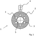
- Fig. 1 shows a plan view of an embodiment of a hermetically sealed LED lamp 1 according to the invention.
- the base 6 of the window 3 is equipped with an LED 10.
- the LED 10 is formed as a chip. It is in particular an SMD (Surface Mounted Device) component.
- leads can, for example in the form of flat conductor tracks, for contacting the LED 10 are located (not shown).
- the window 3 is formed lens-shaped.
- the window 3 is embedded in a channel 7, which in turn is incorporated in the metal cap 2.
- the lenticular configuration of the window 3 is achieved by the surface tension of the glass by making it by placing a glass rod in the channel 7 and then melted.
- the lenticular configured window 3 does not protrude.
- a converter 9 can be introduced into the channel 7. It is in particular a converter with a silicone matrix, which is glued into the channel 7.
- the base 6 is spaced from the metal cap 2 in this embodiment.
- Contact guides in the base 6 are preferably also filled with a solder.
- the metal cap is first produced with the melted windows and separately, the base 6 is equipped with the LEDs 10.
- a gold-tin solder having a melting temperature of below 340 ° C, preferably below 325 ° C, more preferably below 300 ° C.
- the inventive method is suitable not only for the annular LED light shown here, but also for other types of lights, so in particular even those without a central channel.
- the leads 4 are guided around the channel 5 on the bottom.
- Fig. 6 shows a schematic view of a medical instrument, namely the head piece of a dental drill.
- the LED lamp 17 comprises a base 18 made of a ceramic, in particular of aluminum oxide, on which by means of a gold-tin solder a metal cap 19, in particular made of stainless steel, is soldered.
- a LED 22 designed as a chip is arranged, the light of which initially strikes an overlying converter 21, which is arranged beneath the window 20 designed as a lens.
- the metal cap 19 is soldered to the already equipped with the LED 22 socket 18.
Description
Die Erfindung betrifft eine hermetisch abgedichtete LED-Leuchte sowie ein Verfahren zur Herstellung einer hermetisch abgedichteten LED-Leuchte. Insbesondere betrifft die Erfindung eine LED-Leuchte, welche im medizinischen Bereich, also für ärztliche Geräte und Instrumente, verwendet wird.The invention relates to a hermetically sealed LED lamp and a method for producing a hermetically sealed LED lamp. In particular, the invention relates to an LED light, which is used in the medical field, ie for medical devices and instruments.
Im ärztlichen Bereich, insbesondere bei Geräten von Zahnärzten, finden vermehrt LED-Leuchten Verwendung, welche insbesondere auch Teil von ärztlichen Instrumenten sein können. Diese dienen Beleuchtungszwecken, beispielsweise des Ausleuchtens der Mundhöhle eines Patienten, dem Aufspüren von Defektstellen, etwa von Karies, wenn beispielsweise Licht einer bestimmten Wellenlänge, welches das Auffinden von Defektstellen erleichtert, emittiert wird, als Beleuchtung einer Kamera, insbesondere der eines Endoskops, sowie dem Aushärten von Füllmaterialen, etwa beim Aushärten von mittels UV-Licht aushärtbaren Kunststoffen.In the medical field, in particular with devices of dentists, find increasingly LED lights use, which may in particular also be part of medical instruments. These are used for lighting purposes, such as the illumination of the oral cavity of a patient, the detection of defect sites, such as decay, for example, when light of a certain wavelength, which facilitates the finding of defect sites emitted, as illumination of a camera, in particular of an endoscope, and the Curing of filler materials, for example during the curing of UV-curable plastics.
Typischerweise unterliegen derartige Leuchten hohen Belastungen, insbesondere müssen die meisten medizinischen Geräte hermetisch abgedichtet und in manchen Fällen sogar autoklavierbar sein.Typically, such lights are subject to high loads, especially the most medical Devices hermetically sealed and in some cases even be autoclavable.
Die verwendeten Vorrichtungen sollten zudem langlebig sein und keine schädlichen Stoffe abgeben.The devices used should also be durable and deliver no harmful substances.
Insbesondere bei zahnärztlichen Instrumenten sind Griffstücke bekannt, welche eine LED-Lichtquelle aufweisen. Die LED-Lichtquelle ist dabei zumeist in das Gehäuse des Griffstücks integriert und das von der LED-Lichtquelle abgestrahlte Licht wird mittels eines Lichtleiters zu einem Fenster im vorderen Bereich des Griffstücks geleitet, von wo aus dieses in den Mundraum abgestrahlt wird.Especially with dental instruments grips are known which have an LED light source. The LED light source is usually integrated into the housing of the handle and the light emitted by the LED light source is passed by means of a light guide to a window in the front region of the handle, from where it is emitted into the mouth.
Bekannte LED-Leuchten, welche beispielsweise mit einer polymeren Vergussmasse abgedichtet sind, sind in der Regel für einen Einsatz zumindest an der Außenseite eines derartigen ärztlichen Gerätes nicht hinreichend geeignet.Known LED lights, which are sealed, for example, with a polymeric potting compound, are generally not suitable for use at least on the outside of such a medical device.
Das Dokument Schott: "
Das Dokument
Das Dokument
Der Erfindung liegt demgegenüber die Aufgabe zugrunde, eine hermetisch abgedichtete LED-Leuchte bereitzustellen, welche gut in ein ärztliches Instrument integrierbar und den erhöhten Anforderungen im medizinischen Bereich, was Haltbarkeit und Dichtigkeit angeht, gewachsen ist.The invention is based on the object to provide a hermetically sealed LED light, which can be easily integrated into a medical instrument and the increased requirements in the medical field, in terms of durability and tightness grown.
Die Aufgabe der Erfindung wird bereits durch eine hermetisch abgedichtete LED-Leuchte sowie ein Verfahren zum Herstellen einer hermetisch abgedichteten LED-Leuchte nach einem der unabhängigen Ansprüche gelöst.The object of the invention is already achieved by a hermetically sealed LED lamp and a method for producing a hermetically sealed LED lamp according to one of the independent claims.
Bevorzugte Ausführungsformen und Weiterbildungen der Erfindung sind dem Gegenstand der jeweiligen Unteransprüche zu entnehmen.Preferred embodiments and further developments of the invention can be found in the subject matter of the respective subclaims.
Die Erfindung betrifft eine hermetisch abgedichtete LED-Leuchte, also eine LED-Leuchte mit einem Gehäuse, welches zumindest flüssigkeitsdicht ist.The invention relates to a hermetically sealed LED light, that is an LED light with a housing which is at least liquid-tight.
Die LED-Leuchte kann einen Sockel mit einer Mehrzahl von LEDs umfassen.The LED lamp may include a socket having a plurality of LEDs.
Vorzugsweise handelt es sich bei den LEDs um als Chip ausgebildete LEDs, welche direkt auf den Sockel gebondet sind.Preferably, the LEDs are chip-formed LEDs which are directly bonded to the socket.
Derartige LED-Chips können LEDs mit hoher Leistung aufweisen, die Wärme lässt sich gut über den Sockel abführen und die Bauteile sind kompakt ausgebildet.Such LED chips can have LEDs with high power, the heat can be dissipated well on the base and the components are compact.
Der Sockel ist aus einer Keramik ausgebildet. Insbesondere ist der Sockel aus einem Aluminiumoxid und/oder einem Aluminiumnitrid ausgebildet.The base is formed of a ceramic. In particular, the base is formed of an aluminum oxide and / or an aluminum nitride.
Weiter weist die LED-Leuchte eine Metallkappe mit zumindest einem Fenster auf. Vorzugsweise weist die Metallkappe mehrere Fenster auf, welche jeweils den LEDs gegenüberliegen und durch die das Licht aus der LED-Leuchte austritt.Furthermore, the LED lamp has a metal cap with at least one window. Preferably, the metal cap has a plurality of windows, which each face the LEDs and through which the light exits the LED light.
Die Metallkappe ist auf den Sockel gelötet und die LED-Leuchte kann des Weiteren einen Kanal zum Einbringen eines elektrischen, optischen und/oder mechanischen Bauelements aufweisen, welcher sich sowohl durch Sockel als auch durch Kappe erstreckt.The metal cap is soldered to the socket and the LED lamp may further include a channel for introducing an electrical, optical and / or mechanical component which extends through both socket and cap.
Durch die Kombination eines Sockels aus Keramik mit einer erfindungsgemäß mittels eines Gold-Zinn-Lots aufgelöteten Metallkappe konnte ein Bauelement in Form einer LED-Leuchte bereitgestellt werden, welches trotz eines Kanals, der die Bauteile durchdringt, eine hohe Dichtigkeit aufweist.By combining a base made of ceramic with a metal cap soldered according to the invention by means of a gold-tin solder, it was possible to provide a component in the form of an LED lamp, which has a high density despite a channel which penetrates the components.
Der Kanal dient der Aufnahme eines elektrischen oder mechanischen Bauelements, welches insbesondere Teil eines verwendeten ärztlichen Gerätes ist.The channel serves to receive an electrical or mechanical component, which is in particular part of a medical device used.
Beispielsweise kann in dem Kanal ein Bildsensor, insbesondere eine Kamera angeordnet sein, für welche die LED-Leuchte als Lichtquelle dient.For example, in the channel an image sensor, in particular a camera may be arranged, for which the LED light serves as a light source.
Der Kanal kann dabei eine beliebige Form haben, insbesondere eine konische, kreiszylindrische oder auch eckige Form. Weiter ist denkbar, den Kanal gestuft auszubilden, beispielsweise indem Sockel und Kappe einen Kanal mit unterschiedlichem Durchmesser aufweisen. Diese Stufe kann sodann als Anschlag zum verbesserten Halten eines mechanischen oder elektrischen Bauelements verwendet werden.The channel can have any shape, in particular a conical, circular cylindrical or even angular shape. It is also conceivable to design the channel in a stepped manner, for example by having a base and cap with a channel of different diameters. This step can then be used as a stop for improved retention of a mechanical or electrical component.
Bei einer bevorzugten Ausführungsform ist die LED-Leuchte ringförmig mit im Wesentlichen mittig angeordnetem Kanal ausgebildet.In a preferred embodiment, the LED light is annular with a substantially centrally disposed channel.
Die LEDs sind vorzugsweise über den Umfang des so gebildeten Rings verteilt. Die LED-Leuchte kann insbesondere 4 bis 10 LEDs aufweisen.The LEDs are preferably distributed over the circumference of the ring thus formed. In particular, the LED light can have 4 to 10 LEDs.
Eine derartige Leuchte kann insbesondere auch am Kopfstück eines ärztlichen Instruments, beispielsweise auch eines Zahnarztbohrers angeordnet sein. Dabei kann die Antriebswelle des Bohrers und/oder der Bohrer selbst durch den Kanal ragen und die LEDs dienen insbesondere zur Ausleuchtung.Such a lamp may in particular also be arranged on the head piece of a medical instrument, for example a dental drill. In this case, the drive shaft of the drill and / or the drill itself protrude through the channel and the LEDs are used in particular for illumination.
Vorzugsweise umfasst die LED-Leuchte eine Mehrzahl von Fenstern, welche ringförmig verteilt sind.Preferably, the LED lamp comprises a plurality of windows, which are distributed annularly.
Bei einer Weiterbildung der Erfindung sind die Fenster als Linsen ausgebildet.In a further development of the invention, the windows are designed as lenses.
Insbesondere kann über die Fenster das Licht der LEDs fokussiert werden.In particular, the light of the LEDs can be focused via the windows.
Bei einer bevorzugten Ausführungsform sind die Fenster jeweils in einen Kanal der Metallkappe eingelassen. Die Kanäle, in die die Fenster eingelassen sind, haben vorzugsweise eine Höhe zwischen 0,15 und 20 mm. Vorzugsweise reichen die Kanäle jeweils bis zum Sockel, d.h. unmittelbar angrenzend zum jeweiligen Kanal sind Metallkappe und Sockel verlötet.In a preferred embodiment, the windows are each embedded in a channel of the metal cap. The Channels into which the windows are embedded preferably have a height between 0.15 and 20 mm. Preferably, the channels each extend to the base, ie immediately adjacent to the respective channel metal cap and socket are soldered.
Es ist insbesondere vorgesehen, dass die Metallkappe vorzugsweise zylindrisch, insbesondere kreiszylindrisch ausgebildete Kanäle aufweist, in welche Glasfenster, insbesondere in Form von Linsen, eingeschmolzen sind.It is provided in particular that the metal cap preferably has cylindrical, in particular circular-cylindrical channels, into which glass windows, in particular in the form of lenses, are sealed.
Für die Herstellung einer derartigen Metallkappe kann jeweils ein Stück eines Glasstabs in jeweils einen Kanal eingelegt werden. Durch ein Erwärmen schmilzt das Glas und es bildet sich aufgrund der Oberflächenspannung des Glases eine Linse aus.For the production of such a metal cap, a piece of a glass rod can be inserted into a respective channel in each case. By heating, the glass melts and forms a lens due to the surface tension of the glass.
Bei einer Ausführungsvariante umfasst die LED-Leuchte eine Mehrzahl von Fenstern, wobei die Metallkappe angrenzend zu den Fenstern eine Einsenkung umfasst.In one embodiment, the LED lamp comprises a plurality of windows, wherein the metal cap includes a recess adjacent to the windows.
Insbesondere umfasst die Metallkappe an der Oberseite eine Einsenkung, an welche ein Kanal angrenzt.In particular, the metal cap on the upper side comprises a depression, to which a channel adjoins.
Wird nunmehr ein Glasfenster in den Kanal eingeschmolzen, wobei sich eine Linse ausbildet, steht die Linse aufgrund der Einsenkung nicht über die Oberseite der Metallkappe hinaus, so dass, wenn die LED-Leuchte ohne weitere Schutzscheibe verwendet wird, die Fenster bei Berührung eines Gegenstandes nicht beschädigt werden, da die Metallkappe anstößt.Now, if a glass window is melted into the channel, forming a lens, the lens is due to the depression does not exceed the top of the metal cap, so that when the LED light is used without further protective screen, the window upon contact with an object not damaged as the metal cap abuts.
Bei einer Ausführungsform der Erfindung ist in den Kanal unterhalb des Fensters ein Konverter eingelassen. Insbesondere kann ein Konverter mit einer Trägermatrix aus Silikon verwendet werden, in welchem fluoreszierende Partikel, beispielsweise Phosphor, YAG etc., eingebettet sind. Der Konverter lässt sich in den Kanal besonders einfach einbringen, etwa durch Einkleben. Die Verwendung eines Konverters mit einer Silikonmatrix resultiert in einer einfachen Herstellung und einer hohen Temperaturstabilität. Weiter ist auch die Verwendung von Konvertern mit anorganischer Matrix denkbar.In one embodiment of the invention, a converter is embedded in the channel below the window. In particular, a converter can be used with a support matrix of silicone, in which fluorescent particles, such as phosphorus, YAG, etc., are embedded. The converter can be very easily introduced into the channel, for example by gluing. The use of a converter with a silicone matrix results in ease of manufacture and high temperature stability. Furthermore, the use of converters with inorganic matrix is conceivable.
Durch das Einschmelzen eines Glasfensters in einem Kanal, welches vorzugsweise möglichst dicht vor einem optional verwendeten Konverter angeordnet ist, kann eine LED-Leuchte mit großem Abstrahlwinkel bereitgestellt werden.By melting a glass window in a channel, which is preferably arranged as close as possible in front of an optionally used converter, an LED light can be provided with a large beam angle.
Insbesondere kann der Abstrahlwinkel mehr als 85°, vorzugsweise mehr als 90° und besonders bevorzugt mehr als 94° betragen. Unter dem Abstrahlwinkel im Sinne der Erfindung wird der von seitlichen Punkten mit halber maximaler Lichtstärke eingeschlossene Winkel verstanden.In particular, the emission angle can be more than 85 °, preferably more than 90 ° and particularly preferably more than 94 °. For the purposes of the invention, the emission angle is understood to mean the angle enclosed by lateral points with half maximum light intensity.
Die LED-Leuchte kann getrennt ansteuerbare LEDs verschiedener Lichtfarbe umfassen, wobei der Abstrahlwinkel des Lichts von zumindest zwei getrennt ansteuerbaren LEDs unterschiedlich ist.The LED lamp may comprise separately controllable LEDs of different light color, the angle of emission of the light being different from at least two separately controllable LEDs.
Die LED-Leuchte umfasst für verschiedene Verwendungen also LEDs in unterschiedlicher Lichtfarbe. Im Falle der Bereitstellung einer LED-Leuchte für den zahnärztlichen Bereich können dies beispielsweise Leuchten mit im Wesentlichen weißem Licht zum Ausleuchten der Mundhöhle, LEDs spezieller Lichtfarbe zum Erkennen von Karies oder Zahnbelegen sowie LEDs, welche UV-Licht emittieren, sein, welche dem Aushärten von Kunststoff dienen. Diese sind getrennt ansteuerbar. Hierzu umfasst der Sockel eine Mehrzahl elektrischer Durchführungen für die jeweiligen LEDs oder LED-Gruppen.The LED light includes for different uses so LEDs in different light color. For example, in the case of providing an LED light for the dental field, these may include lights having substantially white light for illuminating the oral cavity, LEDs special light color for detecting caries or dental documents as well as LEDs that emit UV light, which are used for curing of plastic. These can be controlled separately. For this purpose, the base comprises a plurality of electrical feedthroughs for the respective LEDs or LED groups.
Es ist insbesondere vorgesehen, dass zumindest eine LED einen Abstrahlwinkel von weniger als 60° und eine andere LED einen Abstrahlwinkel von mehr als 70° aufweist. Weiter ist insbesondere vorgesehen, dass sich der Abstrahlwinkel von mindestens zwei LEDs um zumindest 10°, vorzugsweise um zumindest 20° unterscheidet.In particular, it is provided that at least one LED has an emission angle of less than 60 ° and another LED has an emission angle of more than 70 °. It is further provided in particular that the emission angle of at least two LEDs differs by at least 10 °, preferably by at least 20 °.
Hierzu werden vorzugsweise Fenster verwendet, welche als Linsen mit unterschiedlicher Brennweite und/oder mit unterschiedlichem Öffnungswinkel ausgebildet sind.For this purpose, windows are preferably used, which are designed as lenses with different focal length and / or with different opening angle.
Im Falle des Einschmelzens von Glas können diese beispielsweise durch eine unterschiedliche Form des Kanals und/oder durch ein unterschiedliches Glas bereitgestellt werden.In the case of melting glass, for example, they may be provided by a different shape of the channel and / or by a different glass.
Beispielsweise für LEDs, die UV-Licht emittieren, kann eine Fokussierung des Lichtes und das Abstrahlen mit geringem Abstrahlwinkel sinnvoll sein, wohingegen LEDs zum Ausleuchten des Mundraums einen breiteren Abstrahlwinkel aufweisen.For example, for LEDs which emit UV light, focusing the light and emitting with a low radiation angle may be expedient, whereas LEDs for illuminating the oral cavity have a wider radiation angle.
Die LED-Leuchte ist insbesondere Teil eines ärztlichen Instruments, wobei die LED-Leuchte derart in das ärztliche Instrument eingelassen ist, dass die LED-Leuchte direkt nach außen abstrahlt. Hierunter wird verstanden, dass das Licht nicht über einen Lichtleiter zu einem Austrittsfenster geleitet wird. Es ist aber denkbar, dass in Emissionsrichtung noch ein weiteres Fenster oder eine Schutzscheibe vorgesehen ist. Vorzugsweise bildet die Metallkappe im Bereich der Leuchte samt ihren Fenstern aber den Abschluss des ärztlichen Instruments.In particular, the LED light is part of a medical instrument, wherein the LED light is embedded in the medical instrument so that the LED light emits directly to the outside. This is understood to mean that Light is not passed through an optical fiber to an exit window. However, it is conceivable that in the emission direction yet another window or a protective screen is provided. Preferably, however, the metal cap in the region of the lamp together with its windows forms the conclusion of the medical instrument.
Die Erfindung betrifft des Weiteren ein Verfahren zum Herstellen einer LED-Leuchte, insbesondere ein Verfahren zum Herstellen einer LED-Leuchte, wie sie vorstehend beschrieben wurde.The invention further relates to a method for producing an LED lamp, in particular a method for producing an LED lamp, as described above.
Dabei wird zunächst ein Sockel aus Keramik mit zumindest einer LED bestückt, insbesondere mit einer LED, welche auf einem Chip angeordnet ist. Sodann wird mittels eines Metall-Lots eine Metallkappe auf den Sockel gelötet.In this case, first a socket made of ceramic is equipped with at least one LED, in particular with an LED, which is arranged on a chip. Then a metal cap is soldered to the base by means of a metal solder.
Vorzugsweise wird bereits vor dem Verlöten die Metallkappe mit zumindest einem Fenster versehen, insbesondere durch Aufschmelzen eines Glases in jeweils einem Kanal der Metallkappe.Preferably, the metal cap is provided with at least one window before soldering, in particular by melting a glass in each case a channel of the metal cap.
Denkbar ist auch, das zumindest eine Fenster als Druckeinglasung auszugestalten. Die aus Glas hergestellten Fenster sind vorzugsweise aus einem Material mit guter chemischer Beständigkeit, insbesondere aus einem Silikatglas, beispielsweise aus einem Borosilikatglas, ausgebildet.It is also conceivable to design the at least one window as Druckeinglasung. The windows made of glass are preferably formed of a material with good chemical resistance, in particular of a silicate glass, for example of a borosilicate glass.
Es sind sodann nur noch die Elemente Metallkappe nebst Fenster und Sockel aus Keramik, zusammenzufügen.There are then only the elements metal cap together with windows and base made of ceramic, put together.
Es hat sich gezeigt, dass durch die erfindungsgemäße Verwendung eines Gold-Zinn-Lots eine stabile und hermetisch dichte Verbindung erzielt werden kann, ohne dass die LED-Leuchte derart heiß wird, dass die LED, insbesondere die als Chip ausgebildete LED, beschädigt wird.It has been found that a stable and hermetically sealed connection can be achieved by the use according to the invention of a gold-tin solder, without the LED lamp becoming so hot that the LED, in particular the LED embodied as a chip, is damaged.
Durch die Verwendung eines Gold-Zinn-Lots kann ein autoklavierbares Gehäuse bereit gestellt werden.By using a gold-tin solder an autoclavable housing can be provided.
Weiter ist diese Verbindung auch bei eventuell folgenden Lötprozessen, insbesondere einem Reflowprozess oder bei der Verwendung eines Zinn-Silber-Kupfer-Lots beständig.Furthermore, this compound is also resistant to any subsequent soldering processes, in particular a reflow process or the use of a tin-silver-copper solder.
Vorzugsweise wird ein Lot, insbesondere ein Gold-Zinn-Lot verwendet, dessen Schmelztemperatur bei unter 300°C, besonders bevorzugt bei unter 280°C, liegt.Preferably, a solder, in particular a gold-tin solder is used whose melting temperature is below 300 ° C, more preferably below 280 ° C.
Weiter weist vorzugsweise der Sockel aus Keramik elektrische Durchführungen auf, welche durch einen Metall-Lot hermetisch verriegelt sind.Further, preferably, the base of ceramic electrical feedthroughs, which are hermetically locked by a metal solder.
Auch diese Durchführungen, über die die LEDs kontaktiert sind, werden vorzugsweise vor dem Verlöten von Sockel und Metallkappe ausgebildet.These feedthroughs, via which the LEDs are contacted, are preferably formed prior to the soldering of base and metal cap.
Bei einer Weiterbildung der Erfindung wird zumindest die Metallkappe mit einer Beschichtung versehen, insbesondere mit einer nickel- und/oder goldhaltigen Beschichtung. Insbesondere wird eine Beschichtung aus Hartgold aufgebracht.In a development of the invention, at least the metal cap is provided with a coating, in particular with a coating containing nickel and / or gold. In particular, a coating of hard gold is applied.
Die Metallkappe besteht vorzugsweise aus einem Edelstahl, insbesondere aus einem Edelstahl mit einem geringen Wärmeausdehnungskoeffizienten. So ist die Metallkappe an den niedrigen Wärmeausdehnungskoeffizienten der Keramik angepasst. Insbesondere hat das Material der Metallkappe einen thermischen Wärmeausdehnungskoeffizienten α bei Raumtemperatur von weniger als 15, bevorzugt weniger als 8 und besonders bevorzugt weniger als 5 ppm/K.The metal cap is preferably made of a stainless steel, in particular of a stainless steel with a small Thermal expansion coefficient. Thus, the metal cap is adapted to the low thermal expansion coefficient of the ceramic. In particular, the metal cap material has a thermal coefficient of thermal expansion α at room temperature of less than 15, preferably less than 8, and more preferably less than 5 ppm / K.
Insbesondere besteht die Metallkappe aus einem ferritischen Edelstahl.In particular, the metal cap is made of a ferritic stainless steel.
Bei einer Ausführungsform der Erfindung weichen die thermischen Ausdehnungskoeffizienten α von Metallkappe und dem Material der Fenster weniger als 5 ppm/K, vorzugsweise weniger als 1 ppm/K voneinander ab. Gleiches gilt vorzugsweise für die thermischem Ausdehnungskoeffizienten von Sockel und Metallkappe.In one embodiment of the invention, the thermal expansion coefficients α of the metal cap and the material of the windows are less than 5 ppm / K, preferably less than 1 ppm / K. The same applies preferably to the thermal expansion coefficients of base and metal cap.
Als Lot für die Durchführungen der Kontaktierung der LEDs kann beispielsweise ein Gold-Zinn-, ein Zinn-, ein Kupfer- oder Silber-Lot verwendet werden.For example, a gold-tin, a tin, a copper or silver solder can be used as the solder for the feed-throughs of the LEDs.
Durch die Erfindung konnte eine hermetisch abgedichtete LED-Leuchte bereitgestellt werden, welche sogar autoklavierbar ist.By the invention, a hermetically sealed LED light could be provided, which is even autoclavable.
Der Gegenstand der Erfindung soll im Folgenden bezugnehmend auf Ausführungsbeispiele näher erläutert werden.
-
Fig. 1 zeigt eine Draufsicht auf ein Ausführungsbeispiel einer hermetisch abgedichteten LED-Leuchte. -
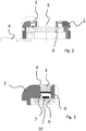
Fig. 2 zeigt eine Schnittansicht derFig. 1 . -
Fig. 3 zeigt eine Detaildarstellung derFig. 2 . -
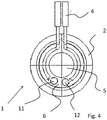
Fig. 4 zeigt eine Draufsicht auf die Unterseite. -
Fig. 5 zeigt in einer schematischen Darstellung die Verwendung der erfindungsgemäßen hermetisch abgedichteten LED-Leuchte in Verbindung mit einem Drittsensor. -
Fig. 6 zeigt eine schematische Ansicht eines ärztlichen Instrumentes, in welches eine erfindungsgemäße, hermetisch abgedichtete LED-Leuchte eingebaut ist. -
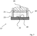
Fig. 7 zeigt ein anderes Ausführungsbeispiel einer hermetisch abgedichteten LED-Leuchte, welche nicht ringförmig ausgebildet ist.
-
Fig. 1 shows a plan view of an embodiment of a hermetically sealed LED lamp. -
Fig. 2 shows a sectional view ofFig. 1 , -
Fig. 3 shows a detailed representation of theFig. 2 , -
Fig. 4 shows a plan view of the bottom. -
Fig. 5 shows a schematic representation of the use of the hermetically sealed LED lamp according to the invention in conjunction with a third sensor. -
Fig. 6 shows a schematic view of a medical instrument, in which a hermetically sealed LED lamp according to the invention is installed. -
Fig. 7 shows another embodiment of a hermetically sealed LED lamp, which is not ring-shaped.
Die LED-Leuchte 1 ist in diesem Ausführungsbeispiel ringförmig ausgebildet. Zu erkennen ist auf der Oberseite die Metallkappe 2, welche eine Mehrzahl von Fenstern 3 aufweist, durch die das Licht der darunterliegenden LEDs abgestrahlt wird.The
Über die Zuleitung 4 kann die LED-Leuchte 1 angeschlossen werden.About the
Die in diesem Ausführungsbeispiel dargestellten sechs Fenster 3 sind über den Umfang der LED-Leuchte 1 verteilt.The six
Weiter zu erkennen ist ein mittig angeordneter Kanal 5 mit kreisförmigem Querschnitt, welcher der Aufnahme eines elektrischen, optischen oder mechanischen Bauelements dient.Further to be seen is a centrally disposed
Zu erkennen ist, dass die Metallkappe 2, welche aus einem Edelstahl besteht, topfförmig ausgebildet ist.It can be seen that the
Ein Sockel 6 aus einer Keramik, insbesondere aus Aluminiumoxid, ist von der Unterseite in die topfförmige Metallkappe 2 eingelassen und mittels eines Gold-Zinn-Lots mit der Metallkappe verlötet.A
Der plattenförmige Sockel 6 ist ebenfalls ringförmig ausgebildet, so dass der Kanal 5 sowohl durch den Sockel 6 als auch durch die Metallkappe 2 verläuft.The plate-shaped
Der Sockel 6 besitzt Durchführungen (nicht dargestellt), über welche über die Zuleitung 4 Strom zur Ansteuerung der LEDs auf die Oberseite geleitet wird.The
Zu erkennen ist, dass der Sockel 6 des Fensters 3 mit einer LED 10 bestückt ist. Die LED 10 ist als Chip ausgebildet. Es handelt sich insbesondere um ein SMD- (Surface Mounted Device) Bauelement.It can be seen that the
Auf der Oberseite des Sockels 6 können sich Zuleitungen, etwa in Form von Flachleiterbahnen, zur Kontaktierung der LED 10 befinden (nicht dargestellt).On the top of the
Zu erkennen ist ferner, dass das Fenster 3 linsenförmig ausgebildet ist.It can also be seen that the
Das Fenster 3 ist in einen Kanal 7 eingelassen, welcher seinerseits in die Metallkappe 2 eingebracht ist.The
Die linsenförmige Ausgestaltung des Fensters 3 kommt durch die Oberflächenspannung des Glases zustande, indem dieses hergestellt wird, indem ein Glasstab in den Kanal 7 eingelegt und sodann aufgeschmolzen wird.The lenticular configuration of the
Oberhalb des Kanals 7 befindet sich eine randseitige Einsenkung 8.Above the
Aufgrund der Einsenkung 8 ragt das linsenförmig ausgestaltete Fenster 3 nicht hervor.Due to the
Optional kann, je nach gewünschter Lichtfarbe, in den Kanal 7 ein Konverter 9 eingebracht sein. Es handelt sich insbesondere um einen Konverter mit einer Silikonmatrix, welcher in den Kanal 7 eingeklebt wird.Optionally, depending on the desired light color, a
Zu erkennen ist ferner, dass der Sockel 6 mit seiner Oberseite auf die Unterseite der topfförmigen Metallkappe 2 gelötet ist.It can also be seen that the
Randseitig ist in diesem Ausführungsbeispiel der Sockel 6 von der Metallkappe 2 beabstandet.On the edge side, the
Durch das Verlöten von Sockel 6 und Metallkappe 2 sowie durch das eingeschmolzene Fenster 3 wird eine hermetische Abdichtung der LED 10 bereitgestellt.By soldering
Kontaktführungen im Sockel 6 sind vorzugsweise ebenfalls mit einem Lot aufgefüllt.Contact guides in the
Für eine Montage der erfindungsgemäßen LED-Leuchte wird zunächst die Metallkappe mit den eingeschmolzenen Fenstern hergestellt und separat hiervon wird der Sockel 6 mit den LEDs 10 bestückt.For mounting the LED lamp according to the invention, the metal cap is first produced with the melted windows and separately, the
Diese beiden Hauptkomponenten werden sodann mittels eines Gold-Zinn-Lots mit einer Schmelztemperatur von unter 340 °C, bevorzugt unter 325 °C, besonders bevorzugt unter 300 °C miteinander verlötet.These two main components are then soldered together by means of a gold-tin solder having a melting temperature of below 340 ° C, preferably below 325 ° C, more preferably below 300 ° C.
Das erfindungsgemäße Verfahren eignet sich nicht nur für die hier dargestellte ringförmige LED-Leuchte, sondern auch für andere Arten von Leuchten, also insbesondere auch solche ohne einen mittigen Kanal.The inventive method is suitable not only for the annular LED light shown here, but also for other types of lights, so in particular even those without a central channel.
Zu erkennen ist der ringförmige Sockel 6, welcher in diesem Ausführungsbeispiel die Durchführungen 11 und 12 aufweist, mittels derer die LEDs auf der Oberseite angesteuert werden.Evident is the
Der Sockel 6 ist in die topfförmige Metallkappe 2 eingelassen.The
Zu erkennen ist ferner der mittige Kanal 5, in welchen ein elektrisches, optisches oder mechanisches Bauelement angeordnet sein kann.Evident is also the
Die Zuleitungen 4 werden um den Kanal 5 auf der Unterseite herumgeführt.The leads 4 are guided around the
Es versteht sich, dass eine LED-Leuchte mit mehreren, getrennt voneinander angesteuerten LEDs in der Regel mehr als die hier dargestellten zwei Durchführungen für Plus- und Minuspol umfasst. Die Treiberschaltungen zum Ansteuern der LEDs befinden sich vorzugsweise nämlich nicht im hermetisch abgedichteten Bereich der hier dargestellten Leuchte, sondern sind extern angeordnet.It is understood that an LED lamp with a plurality of separately controlled LEDs usually includes more than the two feedthroughs shown here for plus and minus pole. The driver circuits for driving the LEDs are preferably not located in the hermetically sealed region of the luminaire shown here, but are arranged externally.
In dem mittigen Kanal 5 ist ein Bildsensor 13 sowie eine Linse 14 angeordnet.In the
Zu sehen ist eine Aufnahme 16, in welche die Bohrer eingesetzt werden und sodann mit einer Antriebswelle verbunden sind.Shown is a
Direkt auf den Kopf des ärztlichen Instruments 15 montiert ist eine erfindungsgemäße, hermetisch abgedichtete LED-Leuchte, deren Licht direkt über die Fenster 3 nach außen abgestrahlt wird.Mounted directly on the head of the
Unter anderem aufgrund der guten Dichtigkeit des Gehäuses der erfindungsgemäßen Leuchte ist es nicht notwendig, die LED-Leuchte im Gehäuse des ärztlichen Instruments anzuordnen und das abgestrahlte Licht über Lichtleiter nach vorne zu führen.Among other things, due to the good tightness of the housing of the luminaire according to the invention, it is not necessary to arrange the LED light in the housing of the medical instrument and to guide the radiated light via light guide to the front.
Die LED-Leuchte 17 umfasst einen Sockel 18 aus einer Keramik, insbesondere aus Aluminiumoxid, auf welchen mittels eines Gold-Zinn-Lots eine Metallkappe 19, insbesondere aus Edelstahl, aufgelötet ist.The
Der Sockel 18 ist nicht in die Kappe 19 eingelassen, sondern stirnseitig aufgesetzt.The
Die Metallkappe 19 ist randseitig abgeschrägt. In dem dadurch entstehenden Spalt sorgt das dort befindliche Lot 23 für eine bessere Verbindung der Bauteile.The
Im Inneren der hermetisch abgedichteten LED-Leuchte 19 ist eine als Chip ausgebildete LED 22 angeordnet, deren Licht zunächst auf einen darüberliegenden Konverter 21 trifft, welcher unterhalb des als Linse ausgebildeten Fensters 20 angeordnet ist.In the interior of the hermetically sealed
Auch zum Herstellen dieser LED-Leuchte 17 wird zunächst ein Fenster 20 aus Glas hergestellt, indem dieses in die Metallkappe 19 eingeschmolzen wird. Optional wird die Metallkappe 19 noch mit dem Konverter 21 bestückt.For producing this
Sodann wird die Metallkappe 19 mit dem bereits mit der LED 22 bestückten Sockel 18 verlötet.Then, the
- 11
- LED-LeuchteLED light
- 22
- Metallkappemetal cap
- 33
- Fensterwindow
- 44
- Zuleitungsupply
- 55
- Kanalchannel
- 66
- Sockelbase
- 77
- Kanalchannel
- 88th
- Einsenkungdepression
- 99
- Konverterconverter
- 1010
- LEDLED
- 1111
- Durchführungexecution
- 1212
- Durchführungexecution
- 1313
- Bildsensorimage sensor
- 1414
- Linselens
- 1515
- ärztliches Instrumentmedical instrument
- 1616
- Aufnahmeadmission
- 1717
- LED-LeuchteLED light
- 1818
- Sockelbase
- 1919
- Metallkappemetal cap
- 2020
- Fensterwindow
- 2121
- Konverterconverter
- 2222
- LEDLED
- 2323
- Lotsolder
Claims (13)
- A method for manufacturing a hermetically sealed LED light (1), wherein first, a base (6) made of ceramics is equipped with at least one LED (10, 22), and then a metal cap (2) is soldered to said base (6) using a metallic solder; wherein prior to the soldering of the metal cap (2) to the base (6), at least one glass window (3) is provided in the metal cap (2) by melting a glass in a passage (7) of the metal cap (2);
characterised in that
the metal cap (2) is soldered to the base (6) using a gold-tin solder. - The method for manufacturing a hermetically sealed LED light (1) according to the preceding claim,
characterised in that the metal cap has a plurality of glass windows, and that the glass windows (3) are integrated by melting a glass in a respective passage (7) of the metal cap (2). - The method for manufacturing a hermetically sealed LED light (1) according to any one of the preceding claims, characterised in that the metal cap (2) is coated, in particular with a coating that contains nickel and/or gold.
- A hermetically sealed LED light (1), comprising a base (6) made of ceramics, which is equipped with at least one LED (10, 22), and a metal cap (2) which is soldered to the base (6) using a metallic solder; wherein at least one glass window is provided in the metal cap (2), which is fused into a passage of the metal cap;
characterised in that
the metal cap (2) is soldered to the base (6) using a gold-tin solder. - The hermetically sealed LED light (1) according to claim 4, wherein the base (6) comprises a plurality of LEDs (10); and wherein
the single metal cap (2) has a plurality of glass windows (3), and wherein the LED light (1) has a passage (5) for introducing an electrical, optical, or mechanical component, which passage extends through the base (6) and through the metal cap (2). - The hermetically sealed LED light (1) according to the preceding claim 5, characterised in that the LED light (1) has an annular shape with centrally arranged passage (5).
- The hermetically sealed LED light (1) according to the preceding claim 6, characterised in that the glass windows (3) are distributed annularly.
- The hermetically sealed LED light (1) according to the preceding claim 7, characterised in that the glass windows (3) have the form of lenses.
- The hermetically sealed LED light (1) according to any one of the preceding claims 5 to 8,
characterised in that the metal cap (2) has a depression adjacent to the glass windows (3). - The hermetically sealed LED light (1) according to any one of the preceding claims 5 to 9,
characterised in that a converter is disposed in the passages (7) below the glass window. - The hermetically sealed LED light (1) according to any one of the preceding claims 5 to 10,
wherein the light comprises separately controllable LEDs (10) of different light colours, wherein at least two separately controllable LEDs have a different light emission angle. - The hermetically sealed LED light (1) according to any one of the preceding claims 5 to 11,
characterised in that the glass windows (3) are provided in the form of lenses which have a different focal length and/or a different aperture angle. - A medical instrument (15), comprising a hermetically sealed LED light (1) according to any one of the preceding claims 4 to 12,
wherein the LED light (1) is embedded in the medical instrument (15) in such a manner that the LED light emits light directly to the outside.
Applications Claiming Priority (2)
| Application Number | Priority Date | Filing Date | Title |
|---|---|---|---|
| DE102015103331.3A DE102015103331B4 (en) | 2015-03-06 | 2015-03-06 | Hermetically sealed LED luminaire, method for producing a hermetically sealed LED luminaire and medical instrument comprising a hermetically sealed LED luminaire |
| DE102015103507 | 2015-03-10 |
Publications (2)
| Publication Number | Publication Date |
|---|---|
| EP3064166A1 EP3064166A1 (en) | 2016-09-07 |
| EP3064166B1 true EP3064166B1 (en) | 2018-07-04 |
Family
ID=55527752
Family Applications (1)
| Application Number | Title | Priority Date | Filing Date |
|---|---|---|---|
| EP16157312.6A Active EP3064166B1 (en) | 2015-03-06 | 2016-02-25 | Hermetically sealed led light, and method for manufacturing a hermetically sealed led light |
Country Status (5)
| Country | Link |
|---|---|
| US (2) | US10890318B2 (en) |
| EP (1) | EP3064166B1 (en) |
| JP (3) | JP6566895B2 (en) |
| KR (1) | KR102034919B1 (en) |
| CN (2) | CN114017688A (en) |
Families Citing this family (2)
| Publication number | Priority date | Publication date | Assignee | Title |
|---|---|---|---|---|
| DE102017212030A1 (en) * | 2017-07-13 | 2019-01-17 | Tridonic Jennersdorf Gmbh | LED / LD lighting device with novel remote phosphor configuration and method of making such a |
| DE102017127723A1 (en) * | 2017-11-23 | 2019-05-23 | Schott Ag | Autoclavable medical device and actuator for an autoclavable medical device |
Family Cites Families (53)
| Publication number | Priority date | Publication date | Assignee | Title |
|---|---|---|---|---|
| FR2568443B1 (en) * | 1984-07-27 | 1986-11-14 | Cepe | COLD-CLOSING BOX SUPPORTING HIGH TEMPERATURES |
| US5531664A (en) * | 1990-12-26 | 1996-07-02 | Olympus Optical Co., Ltd. | Bending actuator having a coil sheath with a fixed distal end and a free proximal end |
| WO1995015060A1 (en) | 1993-11-22 | 1995-06-01 | Apollo Camera, L.L.C. | Single sensor video imaging system and method using sequential color object illumination |
| JPH09140664A (en) * | 1995-11-20 | 1997-06-03 | Osada Res Inst Ltd | Dentistry camera for observing oral cavity |
| WO1998014527A1 (en) | 1996-10-02 | 1998-04-09 | Ormco Corporation | Metal to ceramic attachment in dental appliances |
| US6547721B1 (en) * | 1998-08-07 | 2003-04-15 | Olympus Optical Co., Ltd. | Endoscope capable of being autoclaved |
| JP2000316874A (en) * | 1999-05-07 | 2000-11-21 | Morita Mfg Co Ltd | Dental instrument with illuminating mechanism |
| US6796939B1 (en) * | 1999-08-26 | 2004-09-28 | Olympus Corporation | Electronic endoscope |
| JP3121812B1 (en) * | 1999-10-20 | 2001-01-09 | 株式会社ナカニシ | Lighting equipment for dental and medical instruments |
| JP2003163382A (en) | 2001-11-29 | 2003-06-06 | Matsushita Electric Ind Co Ltd | Package for photodetector or light emitting element |
| US7775685B2 (en) * | 2003-05-27 | 2010-08-17 | Cree, Inc. | Power surface mount light emitting die package |
| JP3668480B2 (en) * | 2003-03-06 | 2005-07-06 | オリンパス株式会社 | Imaging device |
| JP4056930B2 (en) | 2003-05-27 | 2008-03-05 | 株式会社モリタ製作所 | Medical light irradiation device |
| JP4418202B2 (en) * | 2003-10-06 | 2010-02-17 | オリンパス株式会社 | Endoscope |
| US7195482B2 (en) | 2003-12-30 | 2007-03-27 | Ultradent Products, Inc. | Dental curing device having a heat sink for dissipating heat |
| JP2005215213A (en) * | 2004-01-28 | 2005-08-11 | Pentax Corp | Method for manufacturing joined lens unit, joined lens unit, and endoscope |
| US7762950B2 (en) * | 2004-03-25 | 2010-07-27 | Olympus Corporation | Endoscope |
| JP4606954B2 (en) * | 2004-07-15 | 2011-01-05 | Toto株式会社 | Ferrule holding member for optical receptacle, method for manufacturing the same, and optical receptacle using the same |
| JP4917436B2 (en) * | 2004-10-25 | 2012-04-18 | オリンパス株式会社 | Endoscope device |
| DE202005002341U1 (en) | 2005-02-14 | 2005-06-02 | Gutmann, Max | Dental examination electric lamp has ultraviolet LEDs mounted on tooth brush shaped shaft with battery operation and child proof switch |
| JP4652843B2 (en) * | 2005-02-21 | 2011-03-16 | オリンパスメディカルシステムズ株式会社 | Endoscope |
| DE202005020300U1 (en) | 2005-12-27 | 2006-02-16 | Chou, Peter | Lighting device for use in e.g. telephone, has control circuit to receive response signal from noise sensor and to control light intensity of light emitting diode, so that monochromatic light is adjusted with different luminance and color |
| JP5130680B2 (en) | 2006-03-02 | 2013-01-30 | 日亜化学工業株式会社 | Semiconductor device and method for forming the same |
| JP2007311325A (en) * | 2006-04-17 | 2007-11-29 | Citizen Electronics Co Ltd | Light guide plate and its manufacturing method, and back light unit using its light guide plate |
| DE102007022605B4 (en) | 2006-05-24 | 2018-06-21 | Osram Gmbh | Color-adjustable illumination system for imaging illumination |
| EP1870022B1 (en) * | 2006-06-22 | 2016-05-11 | W & H Dentalwerk Bürmoos GmbH | Medical handle with a lighting device and method of manufacturing |
| US8269828B2 (en) * | 2006-12-22 | 2012-09-18 | Perceptron, Inc. | Thermal dissipation for imager head assembly of remote inspection device |
| CN201062739Y (en) * | 2007-05-09 | 2008-05-21 | 常熟鸿邦新能源有限公司 | Combined street lamp structure |
| DE102008033556A1 (en) * | 2008-03-14 | 2009-09-17 | Kaltenbach & Voigt Gmbh | Light source for a dental device |
| JP5223447B2 (en) | 2008-05-12 | 2013-06-26 | 日亜化学工業株式会社 | Semiconductor light emitting device |
| US8390193B2 (en) * | 2008-12-31 | 2013-03-05 | Intematix Corporation | Light emitting device with phosphor wavelength conversion |
| JP5384970B2 (en) * | 2009-02-25 | 2014-01-08 | オリンパス株式会社 | Adapter type endoscope |
| US8328381B2 (en) * | 2009-02-25 | 2012-12-11 | Black & Decker Inc. | Light for a power tool and method of illuminating a workpiece |
| JP5186464B2 (en) * | 2009-11-04 | 2013-04-17 | 株式会社モリタ製作所 | Medical handpiece |
| JP2011100866A (en) * | 2009-11-06 | 2011-05-19 | Toshiba Corp | Thin-film circuit board having leads and connection method therefor |
| DE202010000518U1 (en) | 2010-03-31 | 2011-08-09 | Turck Holding Gmbh | Lamp with a LED arranged in a hermetically sealed housing |
| EP2548530B1 (en) * | 2011-07-19 | 2014-03-19 | W & H Dentalwerk Bürmoos GmbH | Illuminating device for a medical, in particular dental instrument |
| JP5716627B2 (en) * | 2011-10-06 | 2015-05-13 | オムロン株式会社 | Wafer bonding method and bonded portion structure |
| WO2013061838A1 (en) * | 2011-10-27 | 2013-05-02 | オリンパスメディカルシステムズ株式会社 | Endoscope |
| CN102628554A (en) * | 2012-03-22 | 2012-08-08 | 浙江英特来光电科技有限公司 | Three-channel electrode-sharing light-emitting diode (LED) lamp of lens structure |
| JP2013251384A (en) | 2012-05-31 | 2013-12-12 | Seika Sangyo Kk | Light emitting device |
| CN104364982A (en) * | 2012-07-11 | 2015-02-18 | 松下知识产权经营株式会社 | Nitride semiconductor light emitting device |
| KR101373710B1 (en) * | 2012-12-12 | 2014-03-13 | (주)포인트엔지니어링 | Led metal substrate and method for manufacturing the substrate |
| US9133990B2 (en) * | 2013-01-31 | 2015-09-15 | Dicon Fiberoptics Inc. | LED illuminator apparatus, using multiple luminescent materials dispensed onto an array of LEDs, for improved color rendering, color mixing, and color temperature control |
| CN103162236A (en) * | 2013-03-28 | 2013-06-19 | 苏州百纳思光学科技有限公司 | Free-form surface lens for multi-chip seal larger power light-emitting diode (LED) street lamp |
| JP2015002824A (en) | 2013-06-20 | 2015-01-08 | 株式会社中央技研 | Lighting apparatus for medical oral treatment |
| EP2815719B1 (en) * | 2013-06-21 | 2018-10-03 | Kerr Corporation | Dental light curing device |
| JP5891208B2 (en) * | 2013-08-13 | 2016-03-22 | Hoya株式会社 | Endoscope illumination optics |
| EP2842513A1 (en) * | 2013-08-28 | 2015-03-04 | W & H Dentalwerk Bürmoos GmbH | Lighting device for a medical, in particular dental instrument |
| CN203686834U (en) * | 2014-01-26 | 2014-07-02 | 中山市帝光汽配实业有限公司 | LED automobile headlamp |
| JP2015176960A (en) * | 2014-03-14 | 2015-10-05 | 株式会社東芝 | light-emitting device |
| JP6302762B2 (en) * | 2014-06-23 | 2018-03-28 | スタンレー電気株式会社 | Light emitting device and lighting device |
| CN109068948B (en) * | 2016-06-27 | 2021-08-24 | 奥林巴斯株式会社 | Endoscope and method for manufacturing endoscope |
-
2016
- 2016-02-25 EP EP16157312.6A patent/EP3064166B1/en active Active
- 2016-03-03 KR KR1020160025657A patent/KR102034919B1/en active IP Right Grant
- 2016-03-04 US US15/060,866 patent/US10890318B2/en active Active
- 2016-03-04 CN CN202111351477.0A patent/CN114017688A/en active Pending
- 2016-03-04 JP JP2016042331A patent/JP6566895B2/en active Active
- 2016-03-04 CN CN201610125274.2A patent/CN105937708A/en active Pending
-
2017
- 2017-06-23 JP JP2017123344A patent/JP2017162843A/en active Pending
-
2020
- 2020-10-30 JP JP2020183100A patent/JP6985485B2/en active Active
- 2020-11-24 US US17/103,217 patent/US11933485B2/en active Active
Non-Patent Citations (1)
| Title |
|---|
| None * |
Also Published As
| Publication number | Publication date |
|---|---|
| EP3064166A1 (en) | 2016-09-07 |
| KR20160108199A (en) | 2016-09-19 |
| JP6566895B2 (en) | 2019-08-28 |
| JP6985485B2 (en) | 2021-12-22 |
| KR102034919B1 (en) | 2019-10-21 |
| CN105937708A (en) | 2016-09-14 |
| CN114017688A (en) | 2022-02-08 |
| US20160258582A1 (en) | 2016-09-08 |
| US11933485B2 (en) | 2024-03-19 |
| JP2017162843A (en) | 2017-09-14 |
| JP2021028913A (en) | 2021-02-25 |
| JP2016164880A (en) | 2016-09-08 |
| US20210080100A1 (en) | 2021-03-18 |
| US10890318B2 (en) | 2021-01-12 |
Similar Documents
| Publication | Publication Date | Title |
|---|---|---|
| DE60317808T2 (en) | LIGHTING ARRANGEMENT | |
| EP2734142B1 (en) | Illuminating device for a medical, in particular dental instrument | |
| DE102006015336B4 (en) | A semiconductor radiation source, a semiconductor radiation source light curing device, a semiconductor radiation source illumination device, and a semiconductor radiation source illumination device | |
| DE102011005597A1 (en) | lighting device | |
| WO2013139624A1 (en) | Optoelectronic semiconductor chip and headlamp having such a semiconductor chip | |
| DE102015103331B4 (en) | Hermetically sealed LED luminaire, method for producing a hermetically sealed LED luminaire and medical instrument comprising a hermetically sealed LED luminaire | |
| EP3064166B1 (en) | Hermetically sealed led light, and method for manufacturing a hermetically sealed led light | |
| DE102009007650A1 (en) | Illuminant with heat spreading by heat conduction coating and adaptation to the power supply network and manufacturing method thereof | |
| DE102014214603A1 (en) | Semiconductor lamp | |
| WO2017029255A2 (en) | Method for aligning a luminous spot produced on an optical converter, device comprising a luminous spot and use thereof, and converter-cooling body composite having a metallic solder joint | |
| AT12749U1 (en) | PCB LIGHT ELEMENT WITH AT LEAST ONE LED | |
| EP2955740A1 (en) | Lamp and adapter for a lamp | |
| DE102014205470B4 (en) | Lighting device with CoB range | |
| DE102010015068A1 (en) | fiber optic system | |
| DE102014100584A1 (en) | Method for producing optoelectronic semiconductor components and optoelectronic semiconductor component | |
| EP3341975B1 (en) | Method for producing light-emitting semiconductor components | |
| DE102011013278B4 (en) | Housing for high-performance LEDs - "1-layer system" | |
| EP3651680B1 (en) | Led/laser illumination device with a remote phosphor configuration and production method for such a device | |
| EP3123531B1 (en) | Led module having an integrated secondary optical unit | |
| DE102009045175B4 (en) | Lighting device for a dental handpiece and a method for producing and mounting a lighting device | |
| WO2015000814A1 (en) | Optoelectronic semiconductor device | |
| DE10117018A1 (en) | Optical or optoelectronic arrangement | |
| DE102013103024B4 (en) | LED module with ventilation and degassing device | |
| DE102004011911A1 (en) | Transmitting element for light barriers, light grids and the like | |
| DE102009045189A1 (en) | Lighting device for medical or tooth-medical tool holder, has LED connected anti-parallel to another LED, where former LED is switched in forward direction and latter LED is switched opposite in locking direction |
Legal Events
| Date | Code | Title | Description |
|---|---|---|---|
| PUAI | Public reference made under article 153(3) epc to a published international application that has entered the european phase |
Free format text: ORIGINAL CODE: 0009012 |
|
| 17P | Request for examination filed |
Effective date: 20160301 |
|
| AK | Designated contracting states |
Kind code of ref document: A1 Designated state(s): AL AT BE BG CH CY CZ DE DK EE ES FI FR GB GR HR HU IE IS IT LI LT LU LV MC MK MT NL NO PL PT RO RS SE SI SK SM TR |
|
| AX | Request for extension of the european patent |
Extension state: BA ME |
|
| RBV | Designated contracting states (corrected) |
Designated state(s): AL AT BE BG CH CY CZ DE DK EE ES FI FR GB GR HR HU IE IS IT LI LT LU LV MC MK MT NL NO PL PT RO RS SE SI SK SM TR |
|
| STAA | Information on the status of an ep patent application or granted ep patent |
Free format text: STATUS: EXAMINATION IS IN PROGRESS |
|
| 17Q | First examination report despatched |
Effective date: 20170628 |
|
| REG | Reference to a national code |
Ref country code: DE Ref legal event code: R079 Ref document number: 502016001376 Country of ref document: DE Free format text: PREVIOUS MAIN CLASS: A61C0003000000 Ipc: A61C0003020000 |
|
| GRAP | Despatch of communication of intention to grant a patent |
Free format text: ORIGINAL CODE: EPIDOSNIGR1 |
|
| STAA | Information on the status of an ep patent application or granted ep patent |
Free format text: STATUS: GRANT OF PATENT IS INTENDED |
|
| RIC1 | Information provided on ipc code assigned before grant |
Ipc: F21W 131/20 20060101ALI20180112BHEP Ipc: F21Y 101/00 20160101ALI20180112BHEP Ipc: A61C 1/08 20060101ALI20180112BHEP Ipc: H01L 25/16 20060101ALI20180112BHEP Ipc: F21V 31/00 20060101ALI20180112BHEP Ipc: F21V 3/00 20150101ALI20180112BHEP Ipc: A61B 1/06 20060101ALI20180112BHEP Ipc: A61C 3/02 20060101AFI20180112BHEP Ipc: F21K 9/90 20160101ALI20180112BHEP Ipc: F21V 17/10 20060101ALI20180112BHEP Ipc: F21K 9/20 20160101ALI20180112BHEP Ipc: F21V 33/00 20060101ALI20180112BHEP |
|
| INTG | Intention to grant announced |
Effective date: 20180213 |
|
| GRAS | Grant fee paid |
Free format text: ORIGINAL CODE: EPIDOSNIGR3 |
|
| GRAA | (expected) grant |
Free format text: ORIGINAL CODE: 0009210 |
|
| STAA | Information on the status of an ep patent application or granted ep patent |
Free format text: STATUS: THE PATENT HAS BEEN GRANTED |
|
| AK | Designated contracting states |
Kind code of ref document: B1 Designated state(s): AL AT BE BG CH CY CZ DE DK EE ES FI FR GB GR HR HU IE IS IT LI LT LU LV MC MK MT NL NO PL PT RO RS SE SI SK SM TR |
|
| REG | Reference to a national code |
Ref country code: GB Ref legal event code: FG4D Free format text: NOT ENGLISH |
|
| REG | Reference to a national code |
Ref country code: CH Ref legal event code: EP |
|
| REG | Reference to a national code |
Ref country code: AT Ref legal event code: REF Ref document number: 1013689 Country of ref document: AT Kind code of ref document: T Effective date: 20180715 |
|
| REG | Reference to a national code |
Ref country code: IE Ref legal event code: FG4D Free format text: LANGUAGE OF EP DOCUMENT: GERMAN |
|
| REG | Reference to a national code |
Ref country code: DE Ref legal event code: R096 Ref document number: 502016001376 Country of ref document: DE |
|
| REG | Reference to a national code |
Ref country code: NL Ref legal event code: MP Effective date: 20180704 |
|
| REG | Reference to a national code |
Ref country code: LT Ref legal event code: MG4D |
|
| PG25 | Lapsed in a contracting state [announced via postgrant information from national office to epo] |
Ref country code: NL Free format text: LAPSE BECAUSE OF FAILURE TO SUBMIT A TRANSLATION OF THE DESCRIPTION OR TO PAY THE FEE WITHIN THE PRESCRIBED TIME-LIMIT Effective date: 20180704 |
|
| PG25 | Lapsed in a contracting state [announced via postgrant information from national office to epo] |
Ref country code: FI Free format text: LAPSE BECAUSE OF FAILURE TO SUBMIT A TRANSLATION OF THE DESCRIPTION OR TO PAY THE FEE WITHIN THE PRESCRIBED TIME-LIMIT Effective date: 20180704 Ref country code: CZ Free format text: LAPSE BECAUSE OF FAILURE TO SUBMIT A TRANSLATION OF THE DESCRIPTION OR TO PAY THE FEE WITHIN THE PRESCRIBED TIME-LIMIT Effective date: 20180704 Ref country code: LT Free format text: LAPSE BECAUSE OF FAILURE TO SUBMIT A TRANSLATION OF THE DESCRIPTION OR TO PAY THE FEE WITHIN THE PRESCRIBED TIME-LIMIT Effective date: 20180704 Ref country code: PL Free format text: LAPSE BECAUSE OF FAILURE TO SUBMIT A TRANSLATION OF THE DESCRIPTION OR TO PAY THE FEE WITHIN THE PRESCRIBED TIME-LIMIT Effective date: 20180704 Ref country code: BG Free format text: LAPSE BECAUSE OF FAILURE TO SUBMIT A TRANSLATION OF THE DESCRIPTION OR TO PAY THE FEE WITHIN THE PRESCRIBED TIME-LIMIT Effective date: 20181004 Ref country code: SE Free format text: LAPSE BECAUSE OF FAILURE TO SUBMIT A TRANSLATION OF THE DESCRIPTION OR TO PAY THE FEE WITHIN THE PRESCRIBED TIME-LIMIT Effective date: 20180704 Ref country code: GR Free format text: LAPSE BECAUSE OF FAILURE TO SUBMIT A TRANSLATION OF THE DESCRIPTION OR TO PAY THE FEE WITHIN THE PRESCRIBED TIME-LIMIT Effective date: 20181005 Ref country code: IS Free format text: LAPSE BECAUSE OF FAILURE TO SUBMIT A TRANSLATION OF THE DESCRIPTION OR TO PAY THE FEE WITHIN THE PRESCRIBED TIME-LIMIT Effective date: 20181104 Ref country code: RS Free format text: LAPSE BECAUSE OF FAILURE TO SUBMIT A TRANSLATION OF THE DESCRIPTION OR TO PAY THE FEE WITHIN THE PRESCRIBED TIME-LIMIT Effective date: 20180704 Ref country code: NO Free format text: LAPSE BECAUSE OF FAILURE TO SUBMIT A TRANSLATION OF THE DESCRIPTION OR TO PAY THE FEE WITHIN THE PRESCRIBED TIME-LIMIT Effective date: 20181004 |
|
| PG25 | Lapsed in a contracting state [announced via postgrant information from national office to epo] |
Ref country code: ES Free format text: LAPSE BECAUSE OF FAILURE TO SUBMIT A TRANSLATION OF THE DESCRIPTION OR TO PAY THE FEE WITHIN THE PRESCRIBED TIME-LIMIT Effective date: 20180704 Ref country code: LV Free format text: LAPSE BECAUSE OF FAILURE TO SUBMIT A TRANSLATION OF THE DESCRIPTION OR TO PAY THE FEE WITHIN THE PRESCRIBED TIME-LIMIT Effective date: 20180704 Ref country code: HR Free format text: LAPSE BECAUSE OF FAILURE TO SUBMIT A TRANSLATION OF THE DESCRIPTION OR TO PAY THE FEE WITHIN THE PRESCRIBED TIME-LIMIT Effective date: 20180704 Ref country code: AL Free format text: LAPSE BECAUSE OF FAILURE TO SUBMIT A TRANSLATION OF THE DESCRIPTION OR TO PAY THE FEE WITHIN THE PRESCRIBED TIME-LIMIT Effective date: 20180704 |
|
| REG | Reference to a national code |
Ref country code: DE Ref legal event code: R097 Ref document number: 502016001376 Country of ref document: DE |
|
| PG25 | Lapsed in a contracting state [announced via postgrant information from national office to epo] |
Ref country code: IT Free format text: LAPSE BECAUSE OF FAILURE TO SUBMIT A TRANSLATION OF THE DESCRIPTION OR TO PAY THE FEE WITHIN THE PRESCRIBED TIME-LIMIT Effective date: 20180704 Ref country code: EE Free format text: LAPSE BECAUSE OF FAILURE TO SUBMIT A TRANSLATION OF THE DESCRIPTION OR TO PAY THE FEE WITHIN THE PRESCRIBED TIME-LIMIT Effective date: 20180704 Ref country code: RO Free format text: LAPSE BECAUSE OF FAILURE TO SUBMIT A TRANSLATION OF THE DESCRIPTION OR TO PAY THE FEE WITHIN THE PRESCRIBED TIME-LIMIT Effective date: 20180704 |
|
| PLBE | No opposition filed within time limit |
Free format text: ORIGINAL CODE: 0009261 |
|
| STAA | Information on the status of an ep patent application or granted ep patent |
Free format text: STATUS: NO OPPOSITION FILED WITHIN TIME LIMIT |
|
| PG25 | Lapsed in a contracting state [announced via postgrant information from national office to epo] |
Ref country code: DK Free format text: LAPSE BECAUSE OF FAILURE TO SUBMIT A TRANSLATION OF THE DESCRIPTION OR TO PAY THE FEE WITHIN THE PRESCRIBED TIME-LIMIT Effective date: 20180704 Ref country code: SK Free format text: LAPSE BECAUSE OF FAILURE TO SUBMIT A TRANSLATION OF THE DESCRIPTION OR TO PAY THE FEE WITHIN THE PRESCRIBED TIME-LIMIT Effective date: 20180704 Ref country code: SM Free format text: LAPSE BECAUSE OF FAILURE TO SUBMIT A TRANSLATION OF THE DESCRIPTION OR TO PAY THE FEE WITHIN THE PRESCRIBED TIME-LIMIT Effective date: 20180704 |
|
| 26N | No opposition filed |
Effective date: 20190405 |
|
| PG25 | Lapsed in a contracting state [announced via postgrant information from national office to epo] |
Ref country code: SI Free format text: LAPSE BECAUSE OF FAILURE TO SUBMIT A TRANSLATION OF THE DESCRIPTION OR TO PAY THE FEE WITHIN THE PRESCRIBED TIME-LIMIT Effective date: 20180704 |
|
| PG25 | Lapsed in a contracting state [announced via postgrant information from national office to epo] |
Ref country code: MC Free format text: LAPSE BECAUSE OF FAILURE TO SUBMIT A TRANSLATION OF THE DESCRIPTION OR TO PAY THE FEE WITHIN THE PRESCRIBED TIME-LIMIT Effective date: 20180704 Ref country code: LU Free format text: LAPSE BECAUSE OF NON-PAYMENT OF DUE FEES Effective date: 20190225 |
|
| REG | Reference to a national code |
Ref country code: BE Ref legal event code: MM Effective date: 20190228 |
|
| REG | Reference to a national code |
Ref country code: IE Ref legal event code: MM4A |
|
| PG25 | Lapsed in a contracting state [announced via postgrant information from national office to epo] |
Ref country code: IE Free format text: LAPSE BECAUSE OF NON-PAYMENT OF DUE FEES Effective date: 20190225 |
|
| PG25 | Lapsed in a contracting state [announced via postgrant information from national office to epo] |
Ref country code: BE Free format text: LAPSE BECAUSE OF NON-PAYMENT OF DUE FEES Effective date: 20190228 |
|
| PG25 | Lapsed in a contracting state [announced via postgrant information from national office to epo] |
Ref country code: TR Free format text: LAPSE BECAUSE OF FAILURE TO SUBMIT A TRANSLATION OF THE DESCRIPTION OR TO PAY THE FEE WITHIN THE PRESCRIBED TIME-LIMIT Effective date: 20180704 |
|
| PG25 | Lapsed in a contracting state [announced via postgrant information from national office to epo] |
Ref country code: MT Free format text: LAPSE BECAUSE OF FAILURE TO SUBMIT A TRANSLATION OF THE DESCRIPTION OR TO PAY THE FEE WITHIN THE PRESCRIBED TIME-LIMIT Effective date: 20180704 Ref country code: PT Free format text: LAPSE BECAUSE OF FAILURE TO SUBMIT A TRANSLATION OF THE DESCRIPTION OR TO PAY THE FEE WITHIN THE PRESCRIBED TIME-LIMIT Effective date: 20181104 |
|
| PG25 | Lapsed in a contracting state [announced via postgrant information from national office to epo] |
Ref country code: CY Free format text: LAPSE BECAUSE OF FAILURE TO SUBMIT A TRANSLATION OF THE DESCRIPTION OR TO PAY THE FEE WITHIN THE PRESCRIBED TIME-LIMIT Effective date: 20180704 |
|
| PG25 | Lapsed in a contracting state [announced via postgrant information from national office to epo] |
Ref country code: HU Free format text: LAPSE BECAUSE OF FAILURE TO SUBMIT A TRANSLATION OF THE DESCRIPTION OR TO PAY THE FEE WITHIN THE PRESCRIBED TIME-LIMIT; INVALID AB INITIO Effective date: 20160225 |
|
| PGFP | Annual fee paid to national office [announced via postgrant information from national office to epo] |
Ref country code: GB Payment date: 20220223 Year of fee payment: 7 Ref country code: CH Payment date: 20220216 Year of fee payment: 7 Ref country code: AT Payment date: 20220217 Year of fee payment: 7 |
|
| PGFP | Annual fee paid to national office [announced via postgrant information from national office to epo] |
Ref country code: FR Payment date: 20220216 Year of fee payment: 7 |
|
| PG25 | Lapsed in a contracting state [announced via postgrant information from national office to epo] |
Ref country code: MK Free format text: LAPSE BECAUSE OF FAILURE TO SUBMIT A TRANSLATION OF THE DESCRIPTION OR TO PAY THE FEE WITHIN THE PRESCRIBED TIME-LIMIT Effective date: 20180704 |
|
| PGFP | Annual fee paid to national office [announced via postgrant information from national office to epo] |
Ref country code: DE Payment date: 20230216 Year of fee payment: 8 |
|
| P01 | Opt-out of the competence of the unified patent court (upc) registered |
Effective date: 20230516 |
|
| REG | Reference to a national code |
Ref country code: CH Ref legal event code: PL |
|
| REG | Reference to a national code |
Ref country code: AT Ref legal event code: MM01 Ref document number: 1013689 Country of ref document: AT Kind code of ref document: T Effective date: 20230225 |
|
| GBPC | Gb: european patent ceased through non-payment of renewal fee |
Effective date: 20230225 |
|
| PG25 | Lapsed in a contracting state [announced via postgrant information from national office to epo] |
Ref country code: LI Free format text: LAPSE BECAUSE OF NON-PAYMENT OF DUE FEES Effective date: 20230228 Ref country code: CH Free format text: LAPSE BECAUSE OF NON-PAYMENT OF DUE FEES Effective date: 20230228 Ref country code: AT Free format text: LAPSE BECAUSE OF NON-PAYMENT OF DUE FEES Effective date: 20230225 |
|
| PG25 | Lapsed in a contracting state [announced via postgrant information from national office to epo] |
Ref country code: GB Free format text: LAPSE BECAUSE OF NON-PAYMENT OF DUE FEES Effective date: 20230225 |
|
| PG25 | Lapsed in a contracting state [announced via postgrant information from national office to epo] |
Ref country code: GB Free format text: LAPSE BECAUSE OF NON-PAYMENT OF DUE FEES Effective date: 20230225 Ref country code: FR Free format text: LAPSE BECAUSE OF NON-PAYMENT OF DUE FEES Effective date: 20230228 |