EP3064052B1 - Landwirtschaftliches haspelnockensystem - Google Patents
Landwirtschaftliches haspelnockensystem Download PDFInfo
- Publication number
- EP3064052B1 EP3064052B1 EP16158087.3A EP16158087A EP3064052B1 EP 3064052 B1 EP3064052 B1 EP 3064052B1 EP 16158087 A EP16158087 A EP 16158087A EP 3064052 B1 EP3064052 B1 EP 3064052B1
- Authority
- EP
- European Patent Office
- Prior art keywords
- cam track
- header
- cam
- bar
- tine
- Prior art date
- Legal status (The legal status is an assumption and is not a legal conclusion. Google has not performed a legal analysis and makes no representation as to the accuracy of the status listed.)
- Active
Links
- 230000008878 coupling Effects 0.000 claims 1
- 238000010168 coupling process Methods 0.000 claims 1
- 238000005859 coupling reaction Methods 0.000 claims 1
- OCDRLZFZBHZTKQ-NMUBGGKPSA-N onetine Chemical compound C[C@@H](O)[C@@]1(O)C[C@@H](C)[C@@](C)(O)C(=O)OC\C2=C\CN(C)CC[C@@H](OC1=O)C2=O OCDRLZFZBHZTKQ-NMUBGGKPSA-N 0.000 claims 1
- 239000000463 material Substances 0.000 description 27
- 238000004140 cleaning Methods 0.000 description 15
- 239000010902 straw Substances 0.000 description 6
- 230000033001 locomotion Effects 0.000 description 5
- 230000008901 benefit Effects 0.000 description 4
- 230000007723 transport mechanism Effects 0.000 description 4
- 230000032258 transport Effects 0.000 description 3
- 230000009471 action Effects 0.000 description 2
- 239000000428 dust Substances 0.000 description 2
- 230000005484 gravity Effects 0.000 description 2
- 238000003306 harvesting Methods 0.000 description 2
- 230000001788 irregular Effects 0.000 description 2
- 238000000034 method Methods 0.000 description 2
- 230000005540 biological transmission Effects 0.000 description 1
- 238000001035 drying Methods 0.000 description 1
- 230000000694 effects Effects 0.000 description 1
- 238000005188 flotation Methods 0.000 description 1
- 239000012530 fluid Substances 0.000 description 1
- 239000012535 impurity Substances 0.000 description 1
- 239000002245 particle Substances 0.000 description 1
- 230000008569 process Effects 0.000 description 1
- 230000007704 transition Effects 0.000 description 1
- 238000011144 upstream manufacturing Methods 0.000 description 1
Images


Classifications
-
- A—HUMAN NECESSITIES
- A01—AGRICULTURE; FORESTRY; ANIMAL HUSBANDRY; HUNTING; TRAPPING; FISHING
- A01D—HARVESTING; MOWING
- A01D57/00—Delivering mechanisms for harvesters or mowers
- A01D57/01—Devices for leading crops to the mowing apparatus
- A01D57/02—Devices for leading crops to the mowing apparatus using reels
- A01D57/03—Devices for leading crops to the mowing apparatus using reels with supplementary controlled movement of the crop-engaging members, e.g. of the tines
-
- A—HUMAN NECESSITIES
- A01—AGRICULTURE; FORESTRY; ANIMAL HUSBANDRY; HUNTING; TRAPPING; FISHING
- A01D—HARVESTING; MOWING
- A01D2101/00—Lawn-mowers
Definitions
- the present invention relates to agricultural vehicles such as combines and windrowers, and, more particularly, to reel systems used in such vehicles.
- a combine An agricultural harvester known as a "combine” is historically termed such because it combines multiple harvesting functions with a single harvesting unit, such as picking, threshing, separating and cleaning.
- a combine includes a header which removes the crop from a field, and a feeder housing which transports the crop matter into a threshing rotor.
- the threshing rotor rotates within a perforated housing, which may be in the form of adjustable concaves and performs a threshing operation on the crop to remove the grain.
- a perforated housing which may be in the form of adjustable concaves and performs a threshing operation on the crop to remove the grain.
- a cleaning fan blows air through the sieves to discharge chaff and other debris toward the rear of the combine.
- Non-grain crop material such as straw
- a residue system which may utilize a straw chopper to process the non-grain material and direct it out the rear of the combine.
- the combine When the grain tank becomes full, the combine is positioned adjacent a vehicle into which the grain is to be unloaded, such as a semi-trailer, gravity box, straight truck, or the like; and an unloading system on the combine is actuated to transfer the grain into the vehicle.
- the header performs the task of ingathering of the crop material, and for small grain the header typically includes tines that contact some of the crop material to ensure that it engages a cutter bar.
- the cut crop material is moved toward a transport mechanism which takes the crop material to the threshing system.
- Headers can also be included on other agricultural processing systems, such as windrowers, to cut hay or small grain crops and form the cut crop material into a windrow that is deposited on the ground for drying.
- the tines can be mounted to a beam, such as a tube, linked to a rotating element, such as a shaft, to rotate the tines and direct crop material toward the cutter bar and transport mechanism.
- the tine tube is typically linked to a cam, such as a roller, that follows a cam track mounted to the header.
- a cam such as a roller
- An example of such a cam track is found in the United States patent application published as US 2004/139715 A1 .
- cam track typically has a portion which extends in front of the tube linked to the rotating element.
- the front-most portion of the cam track extending out past the tube impedes crop flow to the cutter bar and transport mechanism. This impediment lowers the crop material gathering rate of the header.
- An alternative cam track system is known from the international patent application published as WO 2014/100105 A1 .
- This more complex cam track system uses a circular first cam track that is followed by a first set of rollers (one for each arm/tine tube).
- a second set of rollers (one for each arm/tine tube) follows a respective non-linear second cam track provided in each one of the arms.
- the present invention provides a system and method of controlling the tines of a reel used with an agricultural processing system that reduces the impediment of crop material gathering caused by the cam track.
- the invention in one form is directed to an agricultural processing system including a chassis with a header coupled to the chassis.
- the header provides for the ingathering of agricultural product into the processing system.
- the header includes a reel system having a plurality of arms rotationally coupled to the header and configured to rotate about a central axis.
- the plurality of arms include a first arm and a second arm.
- the first link is pivotally coupled to the first arm and a roller is rotatably coupled to the first link, with the roller rollingly following the cam track.
- a tine bar is pivotally coupled to the second arm.
- the second link is pivotally coupled to both the first link and to the tine bar.
- the cam track defining a plurality of cam distances relative to the central axis, the cam track having a front portion and a rear portion, the rear portion defining at least one cam distance greater than any cam distances of the front portion; a tine bar pivotally coupled to at least one of the plurality of arms; and a roller coupled to the tine bar, the roller rollingly following the cam track.
- An advantage of the present invention is the cam track does not extend in front of the tine bar, which reduces impediment of crop material gathering.
- cam track can allow the tines to gather crop material in front, deliver the crop material to a transport mechanism, release the crop material, and flip between the release point and the front to prevent wrappage.
- tine bar can trail its associated roller following the cam track.
- FIG. 1 there is shown an agricultural processing system in the form of a combine 10, which generally includes a chassis 12, ground engaging wheels 14 and 16, a header 18, a feeder housing 20, an operator cab 22, a threshing and separating system 24, a cleaning system 26, a grain tank 28, and an unloading auger 30.
- Front wheels 14 are larger flotation type wheels, and rear wheels 16 are smaller steerable wheels. Motive force is selectively applied to front wheels 14 through a power plant in the form of a diesel engine 32 and a transmission (not shown).
- combine 10 is shown as including wheels, is also to be understood that combine 10 may include tracks, such as full tracks or half tracks.
- Header 18 is mounted to the front of combine 10 and includes a cutter bar 34 for severing crops from a field during forward motion of combine 10. While the header 18 according to the present invention is shown mounted to the front of a combine harvester 10 in Fig. 1 , the header 18 can also be mounted to the front of a different agricultural processing system, such as a self-propelled windrower.
- a rotatable reel 36 feeds the crop into header 18, and a conveying device 38 feeds the severed crop laterally inwardly from each side toward feeder housing 20. In the case of a self-propelled windrower, the conveying device would feed the severed crop toward a center opening in the header.
- Feeder housing 20 conveys the cut crop to threshing and separating system 24, and is selectively vertically movable using appropriate actuators, such as hydraulic cylinders (not shown).
- Threshing and separating system 24 is of the axial-flow type, and generally includes a rotor 40 at least partially enclosed by and rotatable within a corresponding perforated concave 42.
- the cut crops are threshed and separated by the rotation of rotor 40 within concave 42, and larger elements, such as stalks, leaves and the like are discharged from the rear of combine 10.
- Smaller elements of crop material including grain and non-grain crop material, including particles lighter than grain, such as chaff, dust and straw, are discharged through perforations of concave 42.
- Cleaning system 26 may include an optional pre-cleaning sieve 46, an upper sieve 48 (also known as a chaffer sieve), a lower sieve 50 (also known as a cleaning sieve), and a cleaning fan 52. Grain on sieves 46, 48 and 50 is subjected to a cleaning action by fan 52 which provides an airflow through the sieves to remove chaff and other impurities such as dust from the grain by making this material airborne for discharge from straw hood 54 of combine 10.
- Grain pan 44 and pre-cleaning sieve 46 oscillate in a fore-to-aft manner to transport the grain and finer non-grain crop material to the upper surface of upper sieve 48.
- Upper sieve 48 and lower sieve 50 are vertically arranged relative to each other, and likewise oscillate in a fore-to-aft manner to spread the grain across sieves 48, 50, while permitting the passage of cleaned grain by gravity through the openings of sieves 48, 50.
- Clean grain falls to a clean grain auger 56 positioned crosswise below and in front of lower sieve 50.
- Clean grain auger 56 receives clean grain from each sieve 48, 50 and from bottom pan 58 of cleaning system 26.
- Clean grain auger 56 conveys the clean grain laterally to a generally vertically arranged grain elevator 60 for transport to grain tank 28.
- Tailings from cleaning system 26 fall to a tailings auger trough 62.
- the tailings are transported via tailings auger 64 and return auger 66 to the upstream end of cleaning system 26 for repeated cleaning action.
- a pair of grain tank augers 68 at the bottom of grain tank 28 convey the clean grain laterally within grain tank 28 to unloading auger 30 for discharge from combine 10.
- Residue handling system 70 may include a chopper, counter knives, a windrow door and a residue spreader.
- cam track 74 which is illustrated in dashed lines, represents a prior art cam track with a portion that defines the front-most portion of the reel 36 in a direction of forward travel 96.
- Cam track 72 represents cam track 74 flipped 180 degrees so the cam track 72 does not define a front-most portion of the reel 36 in a direction of travel.
- Cam track 72 does not impede crop to the same degree as the prior art cam track 74.
- a tine bar is directly connected to the roller following the cam track 72, the tine bar will lead the roller in some portions of the cam track.
- cam track 76 can be employed with a linkage system to the tine bars, which is discussed further herein, that allows the rollers following the cam track 76 to lead the tine bars while also having a front-most portion of the cam track 76 be behind the tine bars in the direction of travel.
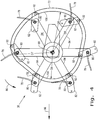
- FIG. 3 there is shown a simplified view of an embodiment of the present invention which includes the cam track 76 shown in Fig. 2 .
- Reel 36 has tines 78, coupled to pivoting tine bars 80, which can also be referred to as "tine tubes,” that have a mounting bar 82 coupled thereto.
- Reel 36 has arms 84, which are rotated in direction 86 about a central axis 88, that can each have a tine bar 80 pivotally coupled thereto.
- a link 90 is pivotally connected to an arm 84 and has a roller 92 that follows cam track 76, and a link 94 is pivotally connected to link 90 and with a mounting bar 82 which is associated with an adjacent following (relative to direction 86) arm 84.
- cam track 76 causes link 90 to move so as to cause link 94 to vary its position and hence the pivotal positions of mounting bar 82 as well as pivoting tine bars 80 and the angular position of tines 78.
- reel 36 rotates in direction 86 and tines 78 are positioned to ingather the crop, bringing it to cutter bar 34 for cutting. After the crop is cut it is positioned on a belt 98 (or it engages auger 38) and proceeds to the threshing section 24. As the crop transitions from cutter bar 34 to belt 98 the tines 78 pivot back away from the crop as can be seen in Fig. 3 . The tines 78 then pivot forward as they rotate on reel 36 so that they are substantially extended as the arms 84 start to come down toward the crop.
- the cam track 76 can have a front portion 100 located in front of the central axis 88 in the forward direction 96 and a rear portion 102 located behind the central axis 88 in the forward direction 96, with the front portion 100 and rear portion 102 defining a plurality of cam distances D1, D2, D3, D4 relative to the central axis 88.
- the rear portion 102 can have a maximum cam distance D4, which is the greatest distance of the cam track 76 relative to the central axis 88, which is greater than any cam distances D1, D2 of the front portion 100.
- This configuration of the cam track 76 forces the tine bars 80 to pivot tips of the tines 78 inward toward the central axis 88 as the rollers 92 roll along the rear portion 102 of the cam track 76, and pivot outward away from the central axis 88 as the rollers 92 roll along the front portion 100 of the cam track 76.
- the tine bars 80 each being mounted an equal tine distance D5 from the central axis 88 and the asymmetry of the cam distances D1, D2, D3, D4 of the cam track 76 relative to the central axis 88 that causes the desired pivoting of the tine bars 80.
- cam track 76 is shown as being an irregular circular shape that is arranged asymmetrically about the central axis 88, a similar effect could be achieved by arranging an irregular circular cam track centrally about the central axis 88 or by arranging a regular circular cam track asymmetrically about the central axis 88, i.e., so the circular cam track is not centered about the central axis 88.
- the maximum cam distance D4 between the cam track 76 and the central axis 88 can be, for example, behind the cutter bar 34.
- cam tracks 76 there can be two similar cam tracks 76, and the associated links and rollers, one on each end of reel 36 to assist in the fluid movement of tines 78.
- FIG. 4 an additional embodiment of the present invention is shown which includes the cam track 72 shown in Fig. 2 . Similar elements between Figs. 3 and 4 are numbered similarly, for ease of reference.
- the cam track 72 is a 180 degree flip of the cam track 74 so the front-most portion of the cam track 72 does not extend in front of the tine bars 80 in the forward direction 96.
- the mounting bars 82 can be elongated to pivotally connect the tine bars 80 to their respective roller 92 following the cam track 72.
- the cam track 72 also has a front portion 104 and a rear portion 106 with a plurality of cam distances D6, D7, D8, D9 relative to the central axis 88, with a maximum cam distance D8 defined between the rear portion 106 and the central axis 88 which is greater than any cam distances D6, D7 of the front portion 104.
- Such a configuration keeps the front-most portion of the cam track 72 behind the tine bars 80 in the direction of forward travel 96 without the need for the linkage system shown in Fig. 3 , but requires a relatively longer cam track 72 compared to cam track 76.
- the present invention has a cam track 72, 76 that does not extend forward into the crop, thereby eliminating any impediment to the crop flow caused by the cam track.
- the two links 90 and 94 if included, allow the roller 92 to follow, or be pulled in cam track 76, which can enhance the robustness of the system.
- the cam track 76 establishes the tine movement pattern so that the tines 78 connected to the tine bars 80 gather the crop material in the front, deliver it to the belt, release the crop and then flip back at the top of their movement to prevent wrapping of the crop material around the tine bars.
Landscapes
- Life Sciences & Earth Sciences (AREA)
- Environmental Sciences (AREA)
- Outside Dividers And Delivering Mechanisms For Harvesters (AREA)
- Harvesting Machines For Specific Crops (AREA)
- Harvester Elements (AREA)
Claims (10)
- Vorsatz (18) eines landwirtschaftlichen Bearbeitungssystems (10), wobei der Vorsatz (18) ein Haspelsystem (36) umfasst, das aufweist:eine Mehrzahl von Armen (84), die drehbar mit dem Vorsatz (18) verbunden sind und dazu ausgestaltet sind, sich um eine Mittelachse (88) zu drehen;eine Kurvenbahn (72, 76), die mit dem Vorsatz (18) verbunden ist;eine Zinkenstange (80), die drehbar mit wenigstens einem der Mehrzahl von Armen (84) verbunden ist; undeine Rolle (92), die mit der Zinkenstange (80) verbunden ist, wobei die Rolle (92) auf rollende Weise der Kurvenbahn (72, 76) folgt;wobei die Kurvenbahn (72, 76) eine Mehrzahl von Kurvenabständen (D1, D2, D3, D4, D6, D7, D8, D9) relativ zur Mittelachse (88) definiert, wobei die Kurvenbahn (72, 76) einen vorderen Abschnitt (100, 104) und einen hinteren Abschnitt (102, 106) aufweist, wobei der hintere Abschnitt (102, 106) wenigstens einen Kurvenabstand (D4, D8) definiert, der größer ist als die Kurvenabstände (D1, D2, D6, D7) des vorderen Abschnitts (100, 104),dadurch gekennzeichnet, dassdie Mehrzahl von Armen (84) einen ersten Arm (84) und einen zweiten Arm (84) umfasst, wobei der zweite Arm (84) schwenkbar mit der Zinkenstange (80) verbunden ist, wobei das Haspelsystem (36) außerdem ein erstes Verbindungsglied (90), das schwenkbar mit dem ersten Arm (84) verbunden ist, und ein zweites Verbindungsglied (94), das schwenkbar mit dem ersten Verbindungsglied (90) und der Zinkenstange (80) verbunden ist, aufweist, wobei die Rolle (92) drehbar mit dem ersten Verbindungsglied (90) verbunden ist.
- Vorsatz (18) nach Anspruch 1, wobei jeder der Mehrzahl von Armen (84) eine Zinkenstange (80) aufweist, die schwenkbar mit ihm verbunden ist.
- Vorsatz (18) nach Anspruch 2, wobei jede Zinkenstange (80) wenigstens einen Zinken (78) trägt.
- Vorsatz (18) nach Anspruch 1, wobei die Kurvenbahn (72, 76) asymmetrisch um die Mittelachse (88) angeordnet ist.
- Vorsatz (18) nach Anspruch 1, wobei sich der vordere Abschnitt (100, 104) der Kurvenbahn (72, 76) in einer Vorwärtsrichtung (96) des Bearbeitungssystems (10) nicht vor die Zinkenstange (80) erstreckt.
- Vorsatz (18) nach einem der vorangehenden Ansprüche, wobei der zweite Arm (84) bezüglich einer Drehrichtung (86) des Haspelsystems (36) dem ersten Arm (84) folgt.
- Vorsatz (18) nach Anspruch 1, des Weiteren mit einer Befestigungsstange (82), die mit der Zinkenstange (80) verbunden ist, wobei die schwenkbare Kopplung der Zinkenstange (80) mit dem zweiten Verbindungsglied (94) durch die Befestigungsstange (82) bewirkt ist.
- Landwirtschaftliches Bearbeitungssystem (10) mit dem Vorsatz (18) nach einem der vorangehenden Ansprüche, wobei der Vorsatz (18) außerdem einen Messerbalken (34) aufweist, der von einem Rahmen getragen wird, wobei die Mittelachse (88) vor dem Messerbalken (34) angeordnet ist.
- Landwirtschaftliches Bearbeitungssystem (10) nach Anspruch 8, wobei der hintere Abschnitt (102, 106) der Kurvenbahn (72, 76) an einem Punkt, der hinter dem Messerbalken (34) liegt, einen maximalen Kurvenabstand (D4, D8) zur Mittelachse (88) definiert.
- Landwirtschaftliches Bearbeitungssystem (10) nach Anspruch 8 oder 9, wobei das landwirtschaftliche Bearbeitungssystem (10) ein Mähdrescher oder ein Schwader ist.
Applications Claiming Priority (1)
| Application Number | Priority Date | Filing Date | Title |
|---|---|---|---|
| US201562126782P | 2015-03-02 | 2015-03-02 |
Publications (2)
| Publication Number | Publication Date |
|---|---|
| EP3064052A1 EP3064052A1 (de) | 2016-09-07 |
| EP3064052B1 true EP3064052B1 (de) | 2018-05-16 |
Family
ID=55484845
Family Applications (1)
| Application Number | Title | Priority Date | Filing Date |
|---|---|---|---|
| EP16158087.3A Active EP3064052B1 (de) | 2015-03-02 | 2016-03-01 | Landwirtschaftliches haspelnockensystem |
Country Status (3)
| Country | Link |
|---|---|
| US (1) | US10542673B2 (de) |
| EP (1) | EP3064052B1 (de) |
| BR (1) | BR102016004651B1 (de) |
Families Citing this family (7)
| Publication number | Priority date | Publication date | Assignee | Title |
|---|---|---|---|---|
| US20170055451A1 (en) * | 2015-09-02 | 2017-03-02 | Hcc, Inc. | Cam track timing adjustment for a pick-up reel of a harvester |
| US20200275609A1 (en) | 2017-09-15 | 2020-09-03 | Cnh Industrial America Llc | Cam Track Adjustment Assembly for a Harvesting Reel |
| US10477765B2 (en) | 2017-09-20 | 2019-11-19 | Cnh Industrial America Llc | Rotatable coupler for a reel arm of a reel header |
| US10568263B2 (en) | 2017-12-14 | 2020-02-25 | Cnh Industrial America Llc | Linkage assembly for header height control |
| BR102019003982A2 (pt) | 2018-03-01 | 2019-09-03 | Cnh Ind America Llc | conjunto de refrigerador hidráulico para uma plataforma de corte de uma colheitadeira agrícola |
| US11617304B2 (en) | 2019-10-25 | 2023-04-04 | Cnh Industrial America Llc | Staggered harvester head reel position adjustment |
| CN115462236B (zh) * | 2022-08-26 | 2023-12-08 | 广东盈峰智能环卫科技有限公司 | 园艺修剪组件、园艺修剪装置和园艺修剪机 |
Family Cites Families (19)
| Publication number | Priority date | Publication date | Assignee | Title |
|---|---|---|---|---|
| US3849974A (en) * | 1970-12-18 | 1974-11-26 | W James | Materials handling devices |
| US4156340A (en) * | 1976-05-27 | 1979-05-29 | Hart-Carter Company | Harvester reel tine-orientation control |
| US4067177A (en) * | 1976-08-09 | 1978-01-10 | Universal Harvester Company, Inc. | Harvester reel |
| US4751809A (en) * | 1985-10-17 | 1988-06-21 | Macdon Industries Ltd. | Reel for a harvesting machine |
| US5987861A (en) * | 1996-07-25 | 1999-11-23 | Duncan; Allister T. | Pea harvester |
| DE10029372C2 (de) * | 1999-08-18 | 2001-10-11 | Schumacher Gmbh Geb | Stellanordnung für die Zinkenträger einer Haspel für ein Schneidwerk |
| US6530202B1 (en) | 2000-11-22 | 2003-03-11 | Wayne A. Guyer | Drive system for combine reel bats |
| US6708475B2 (en) | 2000-11-22 | 2004-03-23 | Wayne A. Guyer | Drive system for combine reel bats |
| EP1297736A1 (de) * | 2001-10-01 | 2003-04-02 | Macdon Industries Ltd | Erntegutbergungsvorsatz mit nockengesteuerten Haspelzinken |
| US6591598B2 (en) * | 2001-10-01 | 2003-07-15 | Macdon Industries Ltd. | Crop harvesting header with cam controlled movement of the reel fingers |
| US6502379B1 (en) * | 2001-10-10 | 2003-01-07 | Macdon Industries Ltd. | Crop harvesting header with cam controlled movement of the reel fingers |
| US6843045B2 (en) * | 2002-08-16 | 2005-01-18 | Hcc, Inc. | Harvester pickup reel controlling the tine tip path |
| CA2525904C (en) * | 2005-11-03 | 2012-01-03 | Macdon Industries Ltd. | Crop harvesting header with crop divider member carried on the reel |
| US8387351B2 (en) | 2010-02-04 | 2013-03-05 | Wayne A. Guyer | Harvester header bat reel assembly tensioning member |
| US8863489B2 (en) * | 2011-03-30 | 2014-10-21 | H & S Manufacturing Co., Inc. | Tine drive cam for windrow merger |
| BR112015011184B1 (pt) * | 2012-12-21 | 2019-10-01 | Agco Corporation | Cabeçote de colheita de cultura para uso com uma máquina de ceifar agrícola" |
| CA2847456C (en) * | 2014-03-26 | 2021-01-19 | Honey Bee Manufacturing Ltd. | Cam reel with complex bat path |
| US9730389B2 (en) * | 2014-11-05 | 2017-08-15 | Hcc, Inc. | Adjustable roller frame assembly for pick-up reel |
| US9775295B2 (en) * | 2015-04-21 | 2017-10-03 | Macdon Industries Ltd. | Drive system for the reel of a crop harvesting header |
-
2016
- 2016-03-01 EP EP16158087.3A patent/EP3064052B1/de active Active
- 2016-03-02 US US15/058,853 patent/US10542673B2/en active Active
- 2016-03-02 BR BR102016004651-3A patent/BR102016004651B1/pt active IP Right Grant
Non-Patent Citations (1)
| Title |
|---|
| None * |
Also Published As
| Publication number | Publication date |
|---|---|
| BR102016004651A2 (pt) | 2016-09-06 |
| US10542673B2 (en) | 2020-01-28 |
| US20160255773A1 (en) | 2016-09-08 |
| EP3064052A1 (de) | 2016-09-07 |
| BR102016004651B1 (pt) | 2020-11-24 |
Similar Documents
| Publication | Publication Date | Title |
|---|---|---|
| EP3064052B1 (de) | Landwirtschaftliches haspelnockensystem | |
| US10588261B2 (en) | Residue handling system for an agricultural harvester | |
| EP3066910B1 (de) | Faltmechanismus für breites weizenschneidwerk | |
| US11277969B2 (en) | Adjusting system for fingerstyle grates of an agricultural harvester | |
| EP3207787B1 (de) | System zur anpassung des dreschkorbs einer landwirtschaftlichen erntemaschine | |
| EP3424293B1 (de) | Rückstandsmanagementsystem mit einer auswahltür für ein landwirtschaftliches fahrzeug | |
| US10292330B2 (en) | Agricultural harvester grain header auger | |
| US9877431B2 (en) | Auger for transverse crop material movement | |
| EP3090614B1 (de) | Abtriebswelle mit drehbewegungsenergiedissipation für eine landwirtschaftliche erntemaschine | |
| EP3395152B1 (de) | Landwirtschaftliche schwadenrutsche mit rollrand | |
| EP3245861B1 (de) | Drescheinrichtung mit zwei reihen von verstellbaren schaufeln für einen zylindrischen läuferkäfig einer landwirtschaftlichen erntemaschine und methode für die kontrolle der schaufeln | |
| EP3011823B1 (de) | Mähdrescher mit einer gewichtsübertragungs- und verteilvorrichtung | |
| US10470369B2 (en) | Agricultural vehicle with active edge windrow chute | |
| EP3157319B1 (de) | Strohschüttleranordnung für eine landwirtschaftliche erntemaschine | |
| WO2016176587A1 (en) | Agricultural harvester auger assembly |
Legal Events
| Date | Code | Title | Description |
|---|---|---|---|
| PUAI | Public reference made under article 153(3) epc to a published international application that has entered the european phase |
Free format text: ORIGINAL CODE: 0009012 |
|
| AK | Designated contracting states |
Kind code of ref document: A1 Designated state(s): AL AT BE BG CH CY CZ DE DK EE ES FI FR GB GR HR HU IE IS IT LI LT LU LV MC MK MT NL NO PL PT RO RS SE SI SK SM TR |
|
| AX | Request for extension of the european patent |
Extension state: BA ME |
|
| STAA | Information on the status of an ep patent application or granted ep patent |
Free format text: STATUS: REQUEST FOR EXAMINATION WAS MADE |
|
| 17P | Request for examination filed |
Effective date: 20170307 |
|
| RBV | Designated contracting states (corrected) |
Designated state(s): AL AT BE BG CH CY CZ DE DK EE ES FI FR GB GR HR HU IE IS IT LI LT LU LV MC MK MT NL NO PL PT RO RS SE SI SK SM TR |
|
| GRAP | Despatch of communication of intention to grant a patent |
Free format text: ORIGINAL CODE: EPIDOSNIGR1 |
|
| RIC1 | Information provided on ipc code assigned before grant |
Ipc: A01D 57/28 20060101ALI20170911BHEP Ipc: A01D 57/03 20060101ALI20170911BHEP Ipc: A01D 41/14 20060101ALN20170911BHEP Ipc: A01D 57/02 20060101ALI20170911BHEP Ipc: A01D 89/00 20060101AFI20170911BHEP Ipc: A01D 41/06 20060101ALN20170911BHEP Ipc: A01D 78/00 20060101ALN20170911BHEP |
|
| STAA | Information on the status of an ep patent application or granted ep patent |
Free format text: STATUS: GRANT OF PATENT IS INTENDED |
|
| INTG | Intention to grant announced |
Effective date: 20171019 |
|
| RIN1 | Information on inventor provided before grant (corrected) |
Inventor name: RAYFIELD, JAMES F. Inventor name: FIGGINS, RYAN M. |
|
| GRAS | Grant fee paid |
Free format text: ORIGINAL CODE: EPIDOSNIGR3 |
|
| GRAA | (expected) grant |
Free format text: ORIGINAL CODE: 0009210 |
|
| STAA | Information on the status of an ep patent application or granted ep patent |
Free format text: STATUS: THE PATENT HAS BEEN GRANTED |
|
| AK | Designated contracting states |
Kind code of ref document: B1 Designated state(s): AL AT BE BG CH CY CZ DE DK EE ES FI FR GB GR HR HU IE IS IT LI LT LU LV MC MK MT NL NO PL PT RO RS SE SI SK SM TR |
|
| REG | Reference to a national code |
Ref country code: GB Ref legal event code: FG4D |
|
| REG | Reference to a national code |
Ref country code: CH Ref legal event code: EP |
|
| REG | Reference to a national code |
Ref country code: IE Ref legal event code: FG4D |
|
| REG | Reference to a national code |
Ref country code: DE Ref legal event code: R096 Ref document number: 602016003032 Country of ref document: DE |
|
| REG | Reference to a national code |
Ref country code: AT Ref legal event code: REF Ref document number: 998693 Country of ref document: AT Kind code of ref document: T Effective date: 20180615 |
|
| REG | Reference to a national code |
Ref country code: NL Ref legal event code: MP Effective date: 20180516 |
|
| REG | Reference to a national code |
Ref country code: LT Ref legal event code: MG4D |
|
| PG25 | Lapsed in a contracting state [announced via postgrant information from national office to epo] |
Ref country code: LT Free format text: LAPSE BECAUSE OF FAILURE TO SUBMIT A TRANSLATION OF THE DESCRIPTION OR TO PAY THE FEE WITHIN THE PRESCRIBED TIME-LIMIT Effective date: 20180516 Ref country code: ES Free format text: LAPSE BECAUSE OF FAILURE TO SUBMIT A TRANSLATION OF THE DESCRIPTION OR TO PAY THE FEE WITHIN THE PRESCRIBED TIME-LIMIT Effective date: 20180516 Ref country code: BG Free format text: LAPSE BECAUSE OF FAILURE TO SUBMIT A TRANSLATION OF THE DESCRIPTION OR TO PAY THE FEE WITHIN THE PRESCRIBED TIME-LIMIT Effective date: 20180816 Ref country code: FI Free format text: LAPSE BECAUSE OF FAILURE TO SUBMIT A TRANSLATION OF THE DESCRIPTION OR TO PAY THE FEE WITHIN THE PRESCRIBED TIME-LIMIT Effective date: 20180516 Ref country code: NO Free format text: LAPSE BECAUSE OF FAILURE TO SUBMIT A TRANSLATION OF THE DESCRIPTION OR TO PAY THE FEE WITHIN THE PRESCRIBED TIME-LIMIT Effective date: 20180816 Ref country code: SE Free format text: LAPSE BECAUSE OF FAILURE TO SUBMIT A TRANSLATION OF THE DESCRIPTION OR TO PAY THE FEE WITHIN THE PRESCRIBED TIME-LIMIT Effective date: 20180516 |
|
| PG25 | Lapsed in a contracting state [announced via postgrant information from national office to epo] |
Ref country code: LV Free format text: LAPSE BECAUSE OF FAILURE TO SUBMIT A TRANSLATION OF THE DESCRIPTION OR TO PAY THE FEE WITHIN THE PRESCRIBED TIME-LIMIT Effective date: 20180516 Ref country code: RS Free format text: LAPSE BECAUSE OF FAILURE TO SUBMIT A TRANSLATION OF THE DESCRIPTION OR TO PAY THE FEE WITHIN THE PRESCRIBED TIME-LIMIT Effective date: 20180516 Ref country code: HR Free format text: LAPSE BECAUSE OF FAILURE TO SUBMIT A TRANSLATION OF THE DESCRIPTION OR TO PAY THE FEE WITHIN THE PRESCRIBED TIME-LIMIT Effective date: 20180516 Ref country code: GR Free format text: LAPSE BECAUSE OF FAILURE TO SUBMIT A TRANSLATION OF THE DESCRIPTION OR TO PAY THE FEE WITHIN THE PRESCRIBED TIME-LIMIT Effective date: 20180817 Ref country code: NL Free format text: LAPSE BECAUSE OF FAILURE TO SUBMIT A TRANSLATION OF THE DESCRIPTION OR TO PAY THE FEE WITHIN THE PRESCRIBED TIME-LIMIT Effective date: 20180516 |
|
| REG | Reference to a national code |
Ref country code: AT Ref legal event code: MK05 Ref document number: 998693 Country of ref document: AT Kind code of ref document: T Effective date: 20180516 |
|
| PG25 | Lapsed in a contracting state [announced via postgrant information from national office to epo] |
Ref country code: DK Free format text: LAPSE BECAUSE OF FAILURE TO SUBMIT A TRANSLATION OF THE DESCRIPTION OR TO PAY THE FEE WITHIN THE PRESCRIBED TIME-LIMIT Effective date: 20180516 Ref country code: PL Free format text: LAPSE BECAUSE OF FAILURE TO SUBMIT A TRANSLATION OF THE DESCRIPTION OR TO PAY THE FEE WITHIN THE PRESCRIBED TIME-LIMIT Effective date: 20180516 Ref country code: RO Free format text: LAPSE BECAUSE OF FAILURE TO SUBMIT A TRANSLATION OF THE DESCRIPTION OR TO PAY THE FEE WITHIN THE PRESCRIBED TIME-LIMIT Effective date: 20180516 Ref country code: SK Free format text: LAPSE BECAUSE OF FAILURE TO SUBMIT A TRANSLATION OF THE DESCRIPTION OR TO PAY THE FEE WITHIN THE PRESCRIBED TIME-LIMIT Effective date: 20180516 Ref country code: CZ Free format text: LAPSE BECAUSE OF FAILURE TO SUBMIT A TRANSLATION OF THE DESCRIPTION OR TO PAY THE FEE WITHIN THE PRESCRIBED TIME-LIMIT Effective date: 20180516 Ref country code: EE Free format text: LAPSE BECAUSE OF FAILURE TO SUBMIT A TRANSLATION OF THE DESCRIPTION OR TO PAY THE FEE WITHIN THE PRESCRIBED TIME-LIMIT Effective date: 20180516 Ref country code: AT Free format text: LAPSE BECAUSE OF FAILURE TO SUBMIT A TRANSLATION OF THE DESCRIPTION OR TO PAY THE FEE WITHIN THE PRESCRIBED TIME-LIMIT Effective date: 20180516 |
|
| REG | Reference to a national code |
Ref country code: DE Ref legal event code: R097 Ref document number: 602016003032 Country of ref document: DE |
|
| PG25 | Lapsed in a contracting state [announced via postgrant information from national office to epo] |
Ref country code: SM Free format text: LAPSE BECAUSE OF FAILURE TO SUBMIT A TRANSLATION OF THE DESCRIPTION OR TO PAY THE FEE WITHIN THE PRESCRIBED TIME-LIMIT Effective date: 20180516 |
|
| PLBE | No opposition filed within time limit |
Free format text: ORIGINAL CODE: 0009261 |
|
| STAA | Information on the status of an ep patent application or granted ep patent |
Free format text: STATUS: NO OPPOSITION FILED WITHIN TIME LIMIT |
|
| 26N | No opposition filed |
Effective date: 20190219 |
|
| PG25 | Lapsed in a contracting state [announced via postgrant information from national office to epo] |
Ref country code: SI Free format text: LAPSE BECAUSE OF FAILURE TO SUBMIT A TRANSLATION OF THE DESCRIPTION OR TO PAY THE FEE WITHIN THE PRESCRIBED TIME-LIMIT Effective date: 20180516 |
|
| PG25 | Lapsed in a contracting state [announced via postgrant information from national office to epo] |
Ref country code: MC Free format text: LAPSE BECAUSE OF FAILURE TO SUBMIT A TRANSLATION OF THE DESCRIPTION OR TO PAY THE FEE WITHIN THE PRESCRIBED TIME-LIMIT Effective date: 20180516 |
|
| REG | Reference to a national code |
Ref country code: CH Ref legal event code: PL |
|
| PG25 | Lapsed in a contracting state [announced via postgrant information from national office to epo] |
Ref country code: AL Free format text: LAPSE BECAUSE OF FAILURE TO SUBMIT A TRANSLATION OF THE DESCRIPTION OR TO PAY THE FEE WITHIN THE PRESCRIBED TIME-LIMIT Effective date: 20180516 Ref country code: LU Free format text: LAPSE BECAUSE OF NON-PAYMENT OF DUE FEES Effective date: 20190301 |
|
| PG25 | Lapsed in a contracting state [announced via postgrant information from national office to epo] |
Ref country code: CH Free format text: LAPSE BECAUSE OF NON-PAYMENT OF DUE FEES Effective date: 20190331 Ref country code: IE Free format text: LAPSE BECAUSE OF NON-PAYMENT OF DUE FEES Effective date: 20190301 Ref country code: LI Free format text: LAPSE BECAUSE OF NON-PAYMENT OF DUE FEES Effective date: 20190331 |
|
| PG25 | Lapsed in a contracting state [announced via postgrant information from national office to epo] |
Ref country code: TR Free format text: LAPSE BECAUSE OF FAILURE TO SUBMIT A TRANSLATION OF THE DESCRIPTION OR TO PAY THE FEE WITHIN THE PRESCRIBED TIME-LIMIT Effective date: 20180516 |
|
| PG25 | Lapsed in a contracting state [announced via postgrant information from national office to epo] |
Ref country code: MT Free format text: LAPSE BECAUSE OF NON-PAYMENT OF DUE FEES Effective date: 20190301 Ref country code: PT Free format text: LAPSE BECAUSE OF FAILURE TO SUBMIT A TRANSLATION OF THE DESCRIPTION OR TO PAY THE FEE WITHIN THE PRESCRIBED TIME-LIMIT Effective date: 20180917 |
|
| PG25 | Lapsed in a contracting state [announced via postgrant information from national office to epo] |
Ref country code: CY Free format text: LAPSE BECAUSE OF FAILURE TO SUBMIT A TRANSLATION OF THE DESCRIPTION OR TO PAY THE FEE WITHIN THE PRESCRIBED TIME-LIMIT Effective date: 20180516 |
|
| PG25 | Lapsed in a contracting state [announced via postgrant information from national office to epo] |
Ref country code: IS Free format text: LAPSE BECAUSE OF FAILURE TO SUBMIT A TRANSLATION OF THE DESCRIPTION OR TO PAY THE FEE WITHIN THE PRESCRIBED TIME-LIMIT Effective date: 20180916 |
|
| PG25 | Lapsed in a contracting state [announced via postgrant information from national office to epo] |
Ref country code: HU Free format text: LAPSE BECAUSE OF FAILURE TO SUBMIT A TRANSLATION OF THE DESCRIPTION OR TO PAY THE FEE WITHIN THE PRESCRIBED TIME-LIMIT; INVALID AB INITIO Effective date: 20160301 |
|
| PG25 | Lapsed in a contracting state [announced via postgrant information from national office to epo] |
Ref country code: MK Free format text: LAPSE BECAUSE OF FAILURE TO SUBMIT A TRANSLATION OF THE DESCRIPTION OR TO PAY THE FEE WITHIN THE PRESCRIBED TIME-LIMIT Effective date: 20180516 |
|
| PGFP | Annual fee paid to national office [announced via postgrant information from national office to epo] |
Ref country code: FR Payment date: 20230322 Year of fee payment: 8 |
|
| PGFP | Annual fee paid to national office [announced via postgrant information from national office to epo] |
Ref country code: IT Payment date: 20230315 Year of fee payment: 8 Ref country code: DE Payment date: 20230323 Year of fee payment: 8 Ref country code: BE Payment date: 20230322 Year of fee payment: 8 |
|
| PGFP | Annual fee paid to national office [announced via postgrant information from national office to epo] |
Ref country code: GB Payment date: 20240320 Year of fee payment: 9 |