EP3064027B1 - Systems, methods, and devices with different radio link failure timers based on user equipment speed - Google Patents
Systems, methods, and devices with different radio link failure timers based on user equipment speed Download PDFInfo
- Publication number
- EP3064027B1 EP3064027B1 EP14847804.3A EP14847804A EP3064027B1 EP 3064027 B1 EP3064027 B1 EP 3064027B1 EP 14847804 A EP14847804 A EP 14847804A EP 3064027 B1 EP3064027 B1 EP 3064027B1
- Authority
- EP
- European Patent Office
- Prior art keywords
- timer
- radio link
- speed
- parameters
- link failure
- Prior art date
- Legal status (The legal status is an assumption and is not a legal conclusion. Google has not performed a legal analysis and makes no representation as to the accuracy of the status listed.)
- Not-in-force
Links
Images



Classifications
-
- H—ELECTRICITY
- H04—ELECTRIC COMMUNICATION TECHNIQUE
- H04L—TRANSMISSION OF DIGITAL INFORMATION, e.g. TELEGRAPHIC COMMUNICATION
- H04L1/00—Arrangements for detecting or preventing errors in the information received
- H04L1/0001—Systems modifying transmission characteristics according to link quality, e.g. power backoff
- H04L1/0023—Systems modifying transmission characteristics according to link quality, e.g. power backoff characterised by the signalling
- H04L1/0027—Scheduling of signalling, e.g. occurrence thereof
-
- G—PHYSICS
- G06—COMPUTING OR CALCULATING; COUNTING
- G06F—ELECTRIC DIGITAL DATA PROCESSING
- G06F9/00—Arrangements for program control, e.g. control units
- G06F9/06—Arrangements for program control, e.g. control units using stored programs, i.e. using an internal store of processing equipment to receive or retain programs
- G06F9/46—Multiprogramming arrangements
- G06F9/48—Program initiating; Program switching, e.g. by interrupt
- G06F9/4806—Task transfer initiation or dispatching
- G06F9/4843—Task transfer initiation or dispatching by program, e.g. task dispatcher, supervisor, operating system
- G06F9/485—Task life-cycle, e.g. stopping, restarting, resuming execution
- G06F9/4856—Task life-cycle, e.g. stopping, restarting, resuming execution resumption being on a different machine, e.g. task migration, virtual machine migration
-
- H—ELECTRICITY
- H04—ELECTRIC COMMUNICATION TECHNIQUE
- H04B—TRANSMISSION
- H04B7/00—Radio transmission systems, i.e. using radiation field
- H04B7/02—Diversity systems; Multi-antenna system, i.e. transmission or reception using multiple antennas
- H04B7/04—Diversity systems; Multi-antenna system, i.e. transmission or reception using multiple antennas using two or more spaced independent antennas
- H04B7/06—Diversity systems; Multi-antenna system, i.e. transmission or reception using multiple antennas using two or more spaced independent antennas at the transmitting station
- H04B7/0613—Diversity systems; Multi-antenna system, i.e. transmission or reception using multiple antennas using two or more spaced independent antennas at the transmitting station using simultaneous transmission
- H04B7/0615—Diversity systems; Multi-antenna system, i.e. transmission or reception using multiple antennas using two or more spaced independent antennas at the transmitting station using simultaneous transmission of weighted versions of same signal
- H04B7/0619—Diversity systems; Multi-antenna system, i.e. transmission or reception using multiple antennas using two or more spaced independent antennas at the transmitting station using simultaneous transmission of weighted versions of same signal using feedback from receiving side
- H04B7/0621—Feedback content
- H04B7/0626—Channel coefficients, e.g. channel state information [CSI]
-
- H—ELECTRICITY
- H04—ELECTRIC COMMUNICATION TECHNIQUE
- H04B—TRANSMISSION
- H04B7/00—Radio transmission systems, i.e. using radiation field
- H04B7/02—Diversity systems; Multi-antenna system, i.e. transmission or reception using multiple antennas
- H04B7/04—Diversity systems; Multi-antenna system, i.e. transmission or reception using multiple antennas using two or more spaced independent antennas
- H04B7/06—Diversity systems; Multi-antenna system, i.e. transmission or reception using multiple antennas using two or more spaced independent antennas at the transmitting station
- H04B7/0613—Diversity systems; Multi-antenna system, i.e. transmission or reception using multiple antennas using two or more spaced independent antennas at the transmitting station using simultaneous transmission
- H04B7/0615—Diversity systems; Multi-antenna system, i.e. transmission or reception using multiple antennas using two or more spaced independent antennas at the transmitting station using simultaneous transmission of weighted versions of same signal
- H04B7/0619—Diversity systems; Multi-antenna system, i.e. transmission or reception using multiple antennas using two or more spaced independent antennas at the transmitting station using simultaneous transmission of weighted versions of same signal using feedback from receiving side
- H04B7/0621—Feedback content
- H04B7/0632—Channel quality parameters, e.g. channel quality indicator [CQI]
-
- H—ELECTRICITY
- H04—ELECTRIC COMMUNICATION TECHNIQUE
- H04B—TRANSMISSION
- H04B7/00—Radio transmission systems, i.e. using radiation field
- H04B7/02—Diversity systems; Multi-antenna system, i.e. transmission or reception using multiple antennas
- H04B7/04—Diversity systems; Multi-antenna system, i.e. transmission or reception using multiple antennas using two or more spaced independent antennas
- H04B7/06—Diversity systems; Multi-antenna system, i.e. transmission or reception using multiple antennas using two or more spaced independent antennas at the transmitting station
- H04B7/0613—Diversity systems; Multi-antenna system, i.e. transmission or reception using multiple antennas using two or more spaced independent antennas at the transmitting station using simultaneous transmission
- H04B7/0615—Diversity systems; Multi-antenna system, i.e. transmission or reception using multiple antennas using two or more spaced independent antennas at the transmitting station using simultaneous transmission of weighted versions of same signal
- H04B7/0619—Diversity systems; Multi-antenna system, i.e. transmission or reception using multiple antennas using two or more spaced independent antennas at the transmitting station using simultaneous transmission of weighted versions of same signal using feedback from receiving side
- H04B7/0636—Feedback format
- H04B7/0639—Using selective indices, e.g. of a codebook, e.g. pre-distortion matrix index [PMI] or for beam selection
-
- H—ELECTRICITY
- H04—ELECTRIC COMMUNICATION TECHNIQUE
- H04L—TRANSMISSION OF DIGITAL INFORMATION, e.g. TELEGRAPHIC COMMUNICATION
- H04L1/00—Arrangements for detecting or preventing errors in the information received
- H04L1/0001—Systems modifying transmission characteristics according to link quality, e.g. power backoff
- H04L1/0023—Systems modifying transmission characteristics according to link quality, e.g. power backoff characterised by the signalling
- H04L1/0026—Transmission of channel quality indication
-
- H—ELECTRICITY
- H04—ELECTRIC COMMUNICATION TECHNIQUE
- H04L—TRANSMISSION OF DIGITAL INFORMATION, e.g. TELEGRAPHIC COMMUNICATION
- H04L1/00—Arrangements for detecting or preventing errors in the information received
- H04L1/12—Arrangements for detecting or preventing errors in the information received by using return channel
- H04L1/16—Arrangements for detecting or preventing errors in the information received by using return channel in which the return channel carries supervisory signals, e.g. repetition request signals
- H04L1/1607—Details of the supervisory signal
-
- H—ELECTRICITY
- H04—ELECTRIC COMMUNICATION TECHNIQUE
- H04L—TRANSMISSION OF DIGITAL INFORMATION, e.g. TELEGRAPHIC COMMUNICATION
- H04L1/00—Arrangements for detecting or preventing errors in the information received
- H04L1/12—Arrangements for detecting or preventing errors in the information received by using return channel
- H04L1/16—Arrangements for detecting or preventing errors in the information received by using return channel in which the return channel carries supervisory signals, e.g. repetition request signals
- H04L1/18—Automatic repetition systems, e.g. Van Duuren systems
- H04L1/1829—Arrangements specially adapted for the receiver end
- H04L1/1854—Scheduling and prioritising arrangements
-
- H—ELECTRICITY
- H04—ELECTRIC COMMUNICATION TECHNIQUE
- H04L—TRANSMISSION OF DIGITAL INFORMATION, e.g. TELEGRAPHIC COMMUNICATION
- H04L1/00—Arrangements for detecting or preventing errors in the information received
- H04L1/12—Arrangements for detecting or preventing errors in the information received by using return channel
- H04L1/16—Arrangements for detecting or preventing errors in the information received by using return channel in which the return channel carries supervisory signals, e.g. repetition request signals
- H04L1/18—Automatic repetition systems, e.g. Van Duuren systems
- H04L1/1867—Arrangements specially adapted for the transmitter end
- H04L1/1887—Scheduling and prioritising arrangements
-
- H—ELECTRICITY
- H04—ELECTRIC COMMUNICATION TECHNIQUE
- H04L—TRANSMISSION OF DIGITAL INFORMATION, e.g. TELEGRAPHIC COMMUNICATION
- H04L47/00—Traffic control in data switching networks
- H04L47/10—Flow control; Congestion control
- H04L47/12—Avoiding congestion; Recovering from congestion
-
- H—ELECTRICITY
- H04—ELECTRIC COMMUNICATION TECHNIQUE
- H04L—TRANSMISSION OF DIGITAL INFORMATION, e.g. TELEGRAPHIC COMMUNICATION
- H04L47/00—Traffic control in data switching networks
- H04L47/10—Flow control; Congestion control
- H04L47/12—Avoiding congestion; Recovering from congestion
- H04L47/122—Avoiding congestion; Recovering from congestion by diverting traffic away from congested entities
-
- H—ELECTRICITY
- H04—ELECTRIC COMMUNICATION TECHNIQUE
- H04L—TRANSMISSION OF DIGITAL INFORMATION, e.g. TELEGRAPHIC COMMUNICATION
- H04L5/00—Arrangements affording multiple use of the transmission path
- H04L5/0001—Arrangements for dividing the transmission path
- H04L5/0003—Two-dimensional division
- H04L5/0005—Time-frequency
- H04L5/0007—Time-frequency the frequencies being orthogonal, e.g. OFDM(A) or DMT
- H04L5/001—Time-frequency the frequencies being orthogonal, e.g. OFDM(A) or DMT the frequencies being arranged in component carriers
-
- H—ELECTRICITY
- H04—ELECTRIC COMMUNICATION TECHNIQUE
- H04L—TRANSMISSION OF DIGITAL INFORMATION, e.g. TELEGRAPHIC COMMUNICATION
- H04L5/00—Arrangements affording multiple use of the transmission path
- H04L5/003—Arrangements for allocating sub-channels of the transmission path
- H04L5/0032—Distributed allocation, i.e. involving a plurality of allocating devices, each making partial allocation
- H04L5/0035—Resource allocation in a cooperative multipoint environment
-
- H—ELECTRICITY
- H04—ELECTRIC COMMUNICATION TECHNIQUE
- H04L—TRANSMISSION OF DIGITAL INFORMATION, e.g. TELEGRAPHIC COMMUNICATION
- H04L5/00—Arrangements affording multiple use of the transmission path
- H04L5/003—Arrangements for allocating sub-channels of the transmission path
- H04L5/0037—Inter-user or inter-terminal allocation
-
- H—ELECTRICITY
- H04—ELECTRIC COMMUNICATION TECHNIQUE
- H04L—TRANSMISSION OF DIGITAL INFORMATION, e.g. TELEGRAPHIC COMMUNICATION
- H04L5/00—Arrangements affording multiple use of the transmission path
- H04L5/003—Arrangements for allocating sub-channels of the transmission path
- H04L5/0048—Allocation of pilot signals, i.e. of signals known to the receiver
-
- H—ELECTRICITY
- H04—ELECTRIC COMMUNICATION TECHNIQUE
- H04L—TRANSMISSION OF DIGITAL INFORMATION, e.g. TELEGRAPHIC COMMUNICATION
- H04L5/00—Arrangements affording multiple use of the transmission path
- H04L5/003—Arrangements for allocating sub-channels of the transmission path
- H04L5/0053—Allocation of signalling, i.e. of overhead other than pilot signals
-
- H—ELECTRICITY
- H04—ELECTRIC COMMUNICATION TECHNIQUE
- H04L—TRANSMISSION OF DIGITAL INFORMATION, e.g. TELEGRAPHIC COMMUNICATION
- H04L5/00—Arrangements affording multiple use of the transmission path
- H04L5/003—Arrangements for allocating sub-channels of the transmission path
- H04L5/0053—Allocation of signalling, i.e. of overhead other than pilot signals
- H04L5/0055—Physical resource allocation for ACK/NACK
-
- H—ELECTRICITY
- H04—ELECTRIC COMMUNICATION TECHNIQUE
- H04L—TRANSMISSION OF DIGITAL INFORMATION, e.g. TELEGRAPHIC COMMUNICATION
- H04L5/00—Arrangements affording multiple use of the transmission path
- H04L5/003—Arrangements for allocating sub-channels of the transmission path
- H04L5/0053—Allocation of signalling, i.e. of overhead other than pilot signals
- H04L5/0057—Physical resource allocation for CQI
-
- H—ELECTRICITY
- H04—ELECTRIC COMMUNICATION TECHNIQUE
- H04L—TRANSMISSION OF DIGITAL INFORMATION, e.g. TELEGRAPHIC COMMUNICATION
- H04L67/00—Network arrangements or protocols for supporting network services or applications
- H04L67/01—Protocols
- H04L67/02—Protocols based on web technology, e.g. hypertext transfer protocol [HTTP]
- H04L67/025—Protocols based on web technology, e.g. hypertext transfer protocol [HTTP] for remote control or remote monitoring of applications
-
- H—ELECTRICITY
- H04—ELECTRIC COMMUNICATION TECHNIQUE
- H04L—TRANSMISSION OF DIGITAL INFORMATION, e.g. TELEGRAPHIC COMMUNICATION
- H04L67/00—Network arrangements or protocols for supporting network services or applications
- H04L67/01—Protocols
- H04L67/10—Protocols in which an application is distributed across nodes in the network
- H04L67/104—Peer-to-peer [P2P] networks
-
- H—ELECTRICITY
- H04—ELECTRIC COMMUNICATION TECHNIQUE
- H04W—WIRELESS COMMUNICATION NETWORKS
- H04W24/00—Supervisory, monitoring or testing arrangements
- H04W24/04—Arrangements for maintaining operational condition
-
- H—ELECTRICITY
- H04—ELECTRIC COMMUNICATION TECHNIQUE
- H04W—WIRELESS COMMUNICATION NETWORKS
- H04W24/00—Supervisory, monitoring or testing arrangements
- H04W24/10—Scheduling measurement reports ; Arrangements for measurement reports
-
- H—ELECTRICITY
- H04—ELECTRIC COMMUNICATION TECHNIQUE
- H04W—WIRELESS COMMUNICATION NETWORKS
- H04W28/00—Network traffic management; Network resource management
- H04W28/02—Traffic management, e.g. flow control or congestion control
-
- H—ELECTRICITY
- H04—ELECTRIC COMMUNICATION TECHNIQUE
- H04W—WIRELESS COMMUNICATION NETWORKS
- H04W40/00—Communication routing or communication path finding
- H04W40/02—Communication route or path selection, e.g. power-based or shortest path routing
- H04W40/22—Communication route or path selection, e.g. power-based or shortest path routing using selective relaying for reaching a BTS [Base Transceiver Station] or an access point
-
- H—ELECTRICITY
- H04—ELECTRIC COMMUNICATION TECHNIQUE
- H04W—WIRELESS COMMUNICATION NETWORKS
- H04W40/00—Communication routing or communication path finding
- H04W40/24—Connectivity information management, e.g. connectivity discovery or connectivity update
-
- H—ELECTRICITY
- H04—ELECTRIC COMMUNICATION TECHNIQUE
- H04W—WIRELESS COMMUNICATION NETWORKS
- H04W48/00—Access restriction; Network selection; Access point selection
- H04W48/08—Access restriction or access information delivery, e.g. discovery data delivery
- H04W48/10—Access restriction or access information delivery, e.g. discovery data delivery using broadcasted information
-
- H—ELECTRICITY
- H04—ELECTRIC COMMUNICATION TECHNIQUE
- H04W—WIRELESS COMMUNICATION NETWORKS
- H04W48/00—Access restriction; Network selection; Access point selection
- H04W48/16—Discovering, processing access restriction or access information
-
- H—ELECTRICITY
- H04—ELECTRIC COMMUNICATION TECHNIQUE
- H04W—WIRELESS COMMUNICATION NETWORKS
- H04W52/00—Power management, e.g. Transmission Power Control [TPC] or power classes
- H04W52/02—Power saving arrangements
- H04W52/0209—Power saving arrangements in terminal devices
- H04W52/0261—Power saving arrangements in terminal devices managing power supply demand, e.g. depending on battery level
- H04W52/0274—Power saving arrangements in terminal devices managing power supply demand, e.g. depending on battery level by switching on or off the equipment or parts thereof
-
- H—ELECTRICITY
- H04—ELECTRIC COMMUNICATION TECHNIQUE
- H04W—WIRELESS COMMUNICATION NETWORKS
- H04W72/00—Local resource management
- H04W72/04—Wireless resource allocation
- H04W72/044—Wireless resource allocation based on the type of the allocated resource
- H04W72/0446—Resources in time domain, e.g. slots or frames
-
- H—ELECTRICITY
- H04—ELECTRIC COMMUNICATION TECHNIQUE
- H04W—WIRELESS COMMUNICATION NETWORKS
- H04W72/00—Local resource management
- H04W72/04—Wireless resource allocation
- H04W72/044—Wireless resource allocation based on the type of the allocated resource
- H04W72/0453—Resources in frequency domain, e.g. a carrier in FDMA
-
- H—ELECTRICITY
- H04—ELECTRIC COMMUNICATION TECHNIQUE
- H04W—WIRELESS COMMUNICATION NETWORKS
- H04W72/00—Local resource management
- H04W72/20—Control channels or signalling for resource management
- H04W72/23—Control channels or signalling for resource management in the downlink direction of a wireless link, i.e. towards a terminal
-
- H—ELECTRICITY
- H04—ELECTRIC COMMUNICATION TECHNIQUE
- H04W—WIRELESS COMMUNICATION NETWORKS
- H04W72/00—Local resource management
- H04W72/20—Control channels or signalling for resource management
- H04W72/25—Control channels or signalling for resource management between terminals via a wireless link, e.g. sidelink
-
- H—ELECTRICITY
- H04—ELECTRIC COMMUNICATION TECHNIQUE
- H04W—WIRELESS COMMUNICATION NETWORKS
- H04W76/00—Connection management
- H04W76/10—Connection setup
- H04W76/14—Direct-mode setup
-
- H—ELECTRICITY
- H04—ELECTRIC COMMUNICATION TECHNIQUE
- H04W—WIRELESS COMMUNICATION NETWORKS
- H04W76/00—Connection management
- H04W76/10—Connection setup
- H04W76/18—Management of setup rejection or failure
-
- H—ELECTRICITY
- H04—ELECTRIC COMMUNICATION TECHNIQUE
- H04W—WIRELESS COMMUNICATION NETWORKS
- H04W76/00—Connection management
- H04W76/20—Manipulation of established connections
- H04W76/27—Transitions between radio resource control [RRC] states
-
- H—ELECTRICITY
- H04—ELECTRIC COMMUNICATION TECHNIQUE
- H04W—WIRELESS COMMUNICATION NETWORKS
- H04W76/00—Connection management
- H04W76/30—Connection release
-
- H—ELECTRICITY
- H04—ELECTRIC COMMUNICATION TECHNIQUE
- H04W—WIRELESS COMMUNICATION NETWORKS
- H04W76/00—Connection management
- H04W76/30—Connection release
- H04W76/38—Connection release triggered by timers
-
- H—ELECTRICITY
- H04—ELECTRIC COMMUNICATION TECHNIQUE
- H04W—WIRELESS COMMUNICATION NETWORKS
- H04W8/00—Network data management
- H04W8/005—Discovery of network devices, e.g. terminals
-
- H—ELECTRICITY
- H04—ELECTRIC COMMUNICATION TECHNIQUE
- H04W—WIRELESS COMMUNICATION NETWORKS
- H04W88/00—Devices specially adapted for wireless communication networks, e.g. terminals, base stations or access point devices
- H04W88/08—Access point devices
-
- H—ELECTRICITY
- H04—ELECTRIC COMMUNICATION TECHNIQUE
- H04W—WIRELESS COMMUNICATION NETWORKS
- H04W92/00—Interfaces specially adapted for wireless communication networks
- H04W92/16—Interfaces between hierarchically similar devices
- H04W92/18—Interfaces between hierarchically similar devices between terminal devices
-
- H—ELECTRICITY
- H04—ELECTRIC COMMUNICATION TECHNIQUE
- H04L—TRANSMISSION OF DIGITAL INFORMATION, e.g. TELEGRAPHIC COMMUNICATION
- H04L1/00—Arrangements for detecting or preventing errors in the information received
- H04L1/12—Arrangements for detecting or preventing errors in the information received by using return channel
-
- H—ELECTRICITY
- H04—ELECTRIC COMMUNICATION TECHNIQUE
- H04W—WIRELESS COMMUNICATION NETWORKS
- H04W84/00—Network topologies
- H04W84/02—Hierarchically pre-organised networks, e.g. paging networks, cellular networks, WLAN [Wireless Local Area Network] or WLL [Wireless Local Loop]
- H04W84/10—Small scale networks; Flat hierarchical networks
- H04W84/12—WLAN [Wireless Local Area Networks]
-
- H—ELECTRICITY
- H04—ELECTRIC COMMUNICATION TECHNIQUE
- H04W—WIRELESS COMMUNICATION NETWORKS
- H04W92/00—Interfaces specially adapted for wireless communication networks
- H04W92/16—Interfaces between hierarchically similar devices
- H04W92/20—Interfaces between hierarchically similar devices between access points
-
- Y—GENERAL TAGGING OF NEW TECHNOLOGICAL DEVELOPMENTS; GENERAL TAGGING OF CROSS-SECTIONAL TECHNOLOGIES SPANNING OVER SEVERAL SECTIONS OF THE IPC; TECHNICAL SUBJECTS COVERED BY FORMER USPC CROSS-REFERENCE ART COLLECTIONS [XRACs] AND DIGESTS
- Y02—TECHNOLOGIES OR APPLICATIONS FOR MITIGATION OR ADAPTATION AGAINST CLIMATE CHANGE
- Y02D—CLIMATE CHANGE MITIGATION TECHNOLOGIES IN INFORMATION AND COMMUNICATION TECHNOLOGIES [ICT], I.E. INFORMATION AND COMMUNICATION TECHNOLOGIES AIMING AT THE REDUCTION OF THEIR OWN ENERGY USE
- Y02D10/00—Energy efficient computing, e.g. low power processors, power management or thermal management
-
- Y—GENERAL TAGGING OF NEW TECHNOLOGICAL DEVELOPMENTS; GENERAL TAGGING OF CROSS-SECTIONAL TECHNOLOGIES SPANNING OVER SEVERAL SECTIONS OF THE IPC; TECHNICAL SUBJECTS COVERED BY FORMER USPC CROSS-REFERENCE ART COLLECTIONS [XRACs] AND DIGESTS
- Y02—TECHNOLOGIES OR APPLICATIONS FOR MITIGATION OR ADAPTATION AGAINST CLIMATE CHANGE
- Y02D—CLIMATE CHANGE MITIGATION TECHNOLOGIES IN INFORMATION AND COMMUNICATION TECHNOLOGIES [ICT], I.E. INFORMATION AND COMMUNICATION TECHNOLOGIES AIMING AT THE REDUCTION OF THEIR OWN ENERGY USE
- Y02D30/00—Reducing energy consumption in communication networks
- Y02D30/70—Reducing energy consumption in communication networks in wireless communication networks
Definitions
- the present disclosure relates to systems, methods, and devices for providing different radio link failure timers based on the speed of user equipment.
- 3GPP Tdoc. R2-132027 "Reduce Service Interruption Time with Adaptive RLF Trigger in HetNets", 3GPP TSG RAN WG2 Meeting #82, May 2013 discusses the impact of RLF trigger (T310) setting on the mobility performance and signaling in HetNets for different scenarios and discussed the possibility to optimize the T310 setting for different scenarios therefore to improve the mobility performance in terms of reducing the RLF rate and minimizing the time of service interruption.
- US 20120088498 A1 relates to an automated coverage hole detection (CHD) method based on modifying the setting of a specific parameter of a UE in, e.g., an LTE-based cellular wireless network.
- CHD coverage hole detection
- Physical RLF events of the UEs, possibly indicative of a coverage hole, are monitored. At least some of the UEs in a given cell are selected for modifying their parameter setting.
- the existence of a coverage hole is detected by analyzing the correlation between the settings of a timer and the probability for the UE to transit to RRC_IDLE mode.
- the settings of the timer are systematically adjusted via eNB signalling to evaluate the characteristics of the observed RLFs.
- Wireless mobile communication technology uses various standards and protocols to transmit data between a base station and a wireless communication device.
- Wireless communication system standards and protocols can include, for example, the 3rd Generation Partnership Project (3GPP) long term evolution (LTE); the Institute of Electrical and Electronics Engineers (IEEE) 802.16 standard, which is commonly known to industry groups as worldwide interoperability for microwave access (WiMAX); and the IEEE 802.11 standard, which is commonly known to industry groups as Wi-Fi.
- 3GPP 3rd Generation Partnership Project
- LTE long term evolution
- IEEE 802.16 which is commonly known to industry groups as worldwide interoperability for microwave access
- Wi-Fi IEEE 802.11 standard
- a base station may include Evolved Universal Terrestrial Radio Access Network (E-UTRAN) Node Bs (also commonly denoted as evolved Node Bs, enhanced Node Bs, eNodeBs, or eNBs) and/or Radio Network Controllers (RNCs) in an E-UTRAN, which communicate with a wireless communication device, known as user equipment (UE).
- EPC evolved packet core
- An evolved packet core (EPC) may communicatively couple the E-UTRAN to an external network, such as the Internet.
- LTE networks include radio access technology and core radio network architecture that provide high data rate, low latency, packet optimization, and improved system capacity and coverage.
- an E-UTRAN may include a plurality of eNodeBs and may communicate with a plurality of UEs. UEs may be handed over from one eNodeB to another as the signal strength of the eNodeBs changes (e.g., due to movement by the UEs).
- a UE may start a radio link failure (RLF) timer (e.g., a T310 timer, a recover timer, or the like) if the signal quality from an eNodeB to which the UE is currently connected falls below a predetermined threshold.
- RLF radio link failure
- an out-of-sync indication may be generated. If more than a specified number of out-of-sync indications are received, the RLF timer may be started. If the CQI is greater than a threshold Qin more than a specified number of times, the RLF timer may be stopped. If the RLF timer expires, an RLF may be declared. RLFs may occur during handover or when a handover is not occurring but may be more prevalent during handovers. If an RLF is declared, the UE may attempt to establish a connection with an eNodeB that has the UE context and/or may enter an idle mode and restart the connection process a new.
- CQI Channel Quality Indicator
- the plurality of UEs may travel at different speeds relative to the eNodeBs.
- one UE may be carried by a person who is stationary or travelling on foot and another may be carried by a person travelling in a car or a high speed train.
- the channel conditions experienced by the UEs may be different.
- the channel condition may change quickly for the rapidly moving UE, and the UE may quickly distance itself from any sources of interference that begin degrading the channel. If given enough time, the UE may be able to recover a radio link with the eNodeB without declaring an RLF.
- the slowly moving UE may be less likely to recover from poor channel conditions. Shadowing and/or a source of interference may degrade performance of the UE for an extended period of time.
- the UE may receive an improved signal by changing to another eNodeB. Thus, performance of the slowly moving UE may be improved by declaring an RLF sooner and restarting the connection establishment process.
- the time until an RLF is declared may be adjusted for each UE to accommodate the different speeds of the various UEs.
- the UE determines the speed at which it is moving and adjusts the RLF timer parameters accordingly.
- the running time of the RLF timer may be increased for rapidly moving UEs, may be decreased for slowly moving UEs, and/or the like.
- the UE may determine the RLF timer parameters for a plurality of speeds in advance and may select the RLF timer parameters corresponding to a current speed when the RLF timer needs to be started. Alternatively, only the RLF parameters for the current speed may be determined.
- the UE may be classified into one of a plurality speed states based on the speed of the UE.
- the speed states may include slow, medium, and/or fast. There may be 2, 3, 4, 5, or more speed states.
- the speeds corresponding to each speed states may be predefined and/or may be communicated to the UE by the eNodeB.
- the UE adjusts the RLF timer parameters by determining which of a plurality of scaling factors should be applied to the RLF timer.
- a scaling factor that causes the RLF timer to expire sooner or does not change the RLF timer may be used for a slowly moving UE.
- a scaling factor that does not change the RLF timer or that causes the RLF timer to expire later may be used for a rapidly moving UE.
- a scaling factor less than one causes the timer to count up more slowly.
- the UE may adjust the RLF timer parameters by determining which of a plurality of RLF timers to use to determine when to declare an RLF.
- the plurality of RLF timers may be configured to run for different lengths of time before expiring.
- the plurality of RLF timers may all be started and only the RLF timer corresponding to the current UE speed may be evaluated when determining whether to declare an RLF. Alternatively, only the RLF timer corresponding to the current UE speed may be started. In an embodiment, a long RLF timer may be used by a rapidly moving UE, and a short RLF timer may be used by a slowly moving UE.
- the UE may receive the RLF timer parameters from an eNodeB.
- the RLF parameters include scaling factors to be used for different speed states.
- the RLF parameters may further include a run time of the T310 timer, run times for a plurality of T310 timers (e.g., a long T310 timer and a short T310 timer), cutoffs for speed states, and/or the like.
- the eNodeB may determine the speed of the UE and send a T310 timer value determined based on the UE speed to the UE.
- the eNodeB uses a lot of resources (e.g., storage resources, processing resources, communication resources, etc.) determining the speed of all connected UEs, tracking the speed, and sending updates to the T310 timer value. Resources can be saved by determining the UE speed only once, but the UE may use a non-optimal T310 timer value if it changes speed.
- the eNodeB may broadcast a high speed timer value and a low speed timer value in a system information block (SIB), and the UE may determine which timer value to use based on its measurements of its own speed.
- SIB system information block
- the eNodeB may not be able to customize timer parameters to individual UEs.
- the eNodeB use a radio resource control (RRC) message (e.g., a connection reconfiguration message) to send timer parameters to the UE.
- RRC radio resource control
- SIB may include default timer parameters that do not account for speed, and the RRC message may further define the timer parameters for different speeds and/or speed states of the UE.
- the RRC message may be sent after the UE first attaches to the eNodeB.
- the RRC message may contain sufficient information for the UE to be able to determine which RLF timer parameters to use based on the UE's own determination of its speed.
- the eNodeB may not need to determine or track UE speed or send multiple RRC messages.
- the RRC message may be a unicast message sent in a one-to-one communication from the eNodeB to the UE and may only need to be sent once, so few communication resources may be used.
- the RLF timer parameters may be customized to the UE.
- the UE may send indications of characteristics, such as identifying information for the UE, to the eNodeB.
- the characteristics may include a manufacturer of the UE, a model of the UE, settings of the UE, a manufacturer of a transceiver, a model of the transceiver, settings of the transceiver, an initial speed of the UE when first becoming attached, and/or the like.
- the eNodeB may determine the RLF timer parameters based on the received indications.
- the eNodeB may further determine the RLF timer parameters based on its own known characteristics (e.g., whether the eNodeB is urban or rural, the presence of shadowing objects, a number of pico cells or other small cells nearby, a number of UEs typically present, etc.).
- the eNodeB may attempt to optimize the RLF timer based on the expected performance of the UE under expected conditions for the different speeds.
- Figure 1 is a schematic diagram of a system 100 comprising a plurality of UEs 120, 130 communicatively coupled to an eNodeB 110.
- the UEs 120, 130 may be moving at different speeds relative to the eNodeB 110.
- a first UE 120 may be held by a person and thus move slowly or not at all.
- a second UE 130 may be integrated into a vehicle and/or may be transported by a vehicle and thus move rapidly.
- the first and second UEs 120, 130 may experience different channel characteristics.
- the first UE 120 may experience slow fading. If a source of interference, shadowing, etc. is present, it may remain so for an extended period of time.
- the second UE 130 may experience fast fading. Sources of interference may quickly enter and exit the range of the second UE 130. Because the UEs 120, 130 experience different channel conditions, different approaches may be needed to recover from poor channel conditions.
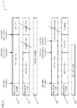
- Figure 2 is a schematic diagram 200 of UE performance during a radio link failure for different RLF timer speeds.
- the UE may detect that the CQI is less than the threshold Qout and generate an out-of-sync indication. Once N310 out-of-sync indications have been generated, the UE may start the T310 timer and attempt to recover the radio link. An in-sync indication may be generated if CQI is greater than the threshold Qin, and the T310 timer may reset if more than N311 in-sync indications are received.
- a radio link failure may be declared.
- the UE may attempt to reestablish the connection and/or may enter idle mode once the radio link failure is declared.
- a slowly moving UE may experience a bad link condition 201 that lasts for an extended period of time.
- the slowly moving UE may need to establish a connection with a new eNodeB to resolve the bad link condition 201.
- the slowly moving UE may have to wait an extended period of time for the RLF timer to expire before it can establish the connection with the new eNodeB.
- the slow moving UE does not need to wait as long for the RLF timer to expire and may connect to the new eNodeB sooner. The UE will spend less time disconnected and provide a better user experience in the short RLF timer situation.
- a rapidly moving UE may experience a bad link condition 202 that lasts for a brief period of time.
- the rapidly moving UE may be able to recover its connection with the current eNodeB if enough time is allowed for the bad link condition 202 to pass.
- the rapidly moving UE may have sufficient time to recover the connection with the current eNodeB after the bad link condition 202 has passed.
- the RLF timer may expire before the bad link condition 202 has passed and/or before the connection could be recovered. The UE will recover faster and provide a better user experience in the long RLF timer situation.
- the extended bad link condition 201 is the most likely kind of bad link condition to occur for the slowly moving UE and the brief bad link condition 202 is the most like kind to occur for the rapidly moving UE
- the average performance of the UEs over time will be best when a short timer is used for slowly moving UEs and a long timer is used for rapidly moving UEs.
- their speed may change over time in an unpredictable manner. Accordingly, the speed of the UE may be measured to determine which link conditions it is likely to experience and thus how long the RLF timer should operate.
- FIG 3A is a schematic diagram of an example implementation of a UE 300a configured to provide a plurality of different T310 timers based on UE speed.
- the UE 300a may include a transceiver 302 configured to communicatively couple the UE 300a to an eNodeB (not shown).
- the transceiver 302 may, inter alia, implement the physical layer and/or data link layer of the UE for communicating with the eNodeB.
- the UE 300a may further include a long T310 timer 304 and a short T310 timer 306.
- the timers 304, 306 may count up to a specified threshold and/or may count down from a specified starting point.
- the timers 304, 306 may expire when they reach the specified threshold and/or zero respectively.
- the run time of each timer 304, 306 may be dynamically adjustable, so the UE 300a may be able to change the run times depending on which eNodeB the UE 300a is connected to. For example, an urban eNodeB may expect different channel characteristics than a rural eNodeB, so the UE 300a may use different timer lengths for the different eNodeBs.
- the UE 300a may further include a speed measuring unit 308.
- the speed measuring unit 308 may estimate how fast the UE 300a is travelling.
- the speed measuring unit 308 may determine speed based on a number, size, and/or location of cells traversed, based on a Doppler shift, based on a satellite navigation system, and/or the like. It is anticipated that further advances will be made in methods for estimating speed, and any such method may be used by the speed measuring unit 308 to determine speed.
- Any units may be used by the speed measuring unit 308 to express the speed, or the speed measuring unit 308 may classify the speed as belonging to one of a plurality of speed states.
- the speed states may be defined based on a set of thresholds, and the appropriate speed state may be determined by comparing the measured speed to the set of thresholds.
- the UE 300a may include a radio resource controller 310, which may control RLF analysis and handovers between eNodeBs for the UE 300a.
- the radio resource controller 310 may transmit characteristics of the UE 300a to the eNodeB and may receive back parameters for the T310 timers 304, 306.
- the parameters may be communicated to the radio resource controller 310 in an RRC message.
- the radio resource controller 310 may parse the RRC message and may configure the T310 timers 304, 306 based on the received parameters.
- the radio resource controller 310 may receive the speed and/or speed state of the UE 300a from the speed measuring unit 308 and determine which T310 timer 304, 306 to use based on the received speed and/or speed state.
- the radio resource controller 310 may start one or both of the T310 timers 304, 306 when radio link problems are detected and may declare an RLF when the appropriate T310 timer 304, 306 expires.
- the transceiver 302, T310 timers 304, 306, speed measuring unit 308, and radio resource controller 310 are illustrated as separate units, the functionalities may be combined into fewer units and/or further separated into additional units in other embodiments.
- Figure 3B is a schematic diagram of an embodiment of a UE 300b configured to adjust a T310 timer speed based on UE speed.
- the UE 300b may include a transceiver 302, which may be substantially similar to the transceiver 302 of the UE 300a.
- the UEs 300a, 300b may speed measuring units 308 that are substantially similar to one another. Rather than having two T310 timers 304, 306, the UE 300b may include a single T310 timer 314. The T310 timer 314 may be adjusted by a scaling unit 316 to account for variations in speed of the UE 300b.
- the UE 300b may also include a radio resource controller 320.
- the radio resource controller 320 may be similar to the radio resource controller 310, but the radio resource controller 320 may control the T310 timer 314 and the scaling unit 316 rather than the two T310 timers 304, 306.
- the radio resource controller 320 may receive scaling unit parameters for one or more speeds and/or speed states.
- one speed state may use a default scaling, so only the other speed state(s) may need scaling unit parameters.
- the radio resource controller 320 may receive the speed and/or speed state from the speed measuring unit 308 and may instruct the scaling unit 316 to use a particular scaling factor based on the speed and/or speed state.
- the T310 timer 314 may count up to a specified threshold and/or count down from a specified starting point.
- the scaling unit 316 may be configured based on the design of the T310 timer 314.
- the scaling factor may be multiplied by the specified threshold, the specified starting point, the current count of the T310 timer 312, and/or the like.
- the radio resource controller 320 may determine when the scaled T310 timer has expired and may declare an RLF when the scaled T310 timer has expired.
- the transceiver 302, T310 timer 314, scaling unit 316, speed measuring unit 308, and radio resource controller 320 are illustrated as separate units, the functionalities may be combined into fewer units and/or further separated into additional units in other embodiments.
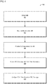
- FIG. 4 is a flow diagram of a method 400 for receiving information on T310 timer speeds.
- the method 400 may begin with an eNodeB being detected 402, for example, by a UE.
- the eNodeB may be detected as a result of the UE first being turned on, as a part of a normal handoff procedure, and/or the like.
- the UE may request 404 attachment to the detected eNodeB.
- the UE may transmit a connection request to the detected eNodeB, and/or a handover request may be sent on the UE's behalf.
- characteristics of the UE may be provided 406 to the eNodeB. For example, identifying information for the UE (e.g., a manufacturer of the UE, a model of the UE, etc.), settings of the UE, a manufacturer of a transceiver, a model of the transceiver, settings of the transceiver, an initial speed of the UE, and/or the like may be provided to the eNodeB.
- the eNodeB may request the information it wants, and/or a predetermined set of information may be provided to the eNodeB. Based on the provided information about the UE and/or already known information about the eNodeB, the eNodeB may determine T310 timer parameters.
- An RRC message containing the T310 timer parameters may be received 408 from the eNodeB.
- the RRC message may be a connection reconfiguration message.
- the T310 parameters may include run times for a short timer and a long timer, scaling factors for different speeds, and/or the like.
- the T310 timer parameters may include speed divisions and/or definitions of speed states that indicate which timer and/or scaling factor should be used for each UE speed.
- the T310 timer may be configured 410 based on the T310 timer parameters received in the RRC message. Configuring 410 the T310 timer parameters may include configuring the T310 timer to operate using the parameters for the current UE speed. The UE speed may be continually monitored, and the parameters may be updated as the UE speed changes. Alternatively, or in addition, the T310 timer may be configured with all the received parameters, and the particular parameters to be used may be determined based on the UE speed when the T310 timer is needed.
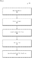
- Figure 5 is a flow diagram of a method 500 for determining whether to declare a radio link failure.
- the method 500 may begin when a bad radio link is detected 502.
- Detecting 502 the bad radio link may include determining whether the CQI is less than a threshold Qout and generating an out-of-sync indication.
- Detecting 502 the bad radio link may further include determining that more than a specified number of out-of-sync indications have been generated (e.g., more than a number N310 specified by an eNodeB). If more than the specified number of out-of-sync indications have been generated, it may be determined that the radio link is bad. Otherwise, the CQI may continue to be monitored.
- the UE speed may be determined 504 in response to the bad radio link being detected 502. Alternatively, or in addition, the UE speed may have previously determined and may not need to be determined again. Determining 504 the UE speed may include retrieving a continually updated UE speed.
- the UE speed may be in any of various units, and/or the UE speed may be specified as a speed state. For example, one embodiment may include UE speed states of fast and slow, and another embodiment may include UE speed states of fast, medium, and slow.
- the speeds corresponding to each speed state may be specified by the eNodeB, predetermined, defined by a standard, and/or the like.
- the parameters for the T310 timer may be selected 506 based on the UE speed determined 504.
- Selecting 506 the parameters may include determining which of a plurality of T310 timers to use, determining a scaling factor for the T310 timer, determining a run time for the T310 timer, and/or the like.
- the parameters for the T310 timer may have been determined previously, for example, when a UE speed was previously measured. In such embodiments, the T310 timer parameters may not need to be selected 506 again.
- the T310 timer may be started 508.
- the T310 timer may count down from a specified starting point, may count up to a specified threshold, and/or the like.
- the T310 timer may continue to operate as long as fewer than a specified number of in-sync indications have been received. For example, an in-sync indication may be generated each time the CQI is greater than a threshold Qin. If more than the specified number of in-sync indications are received, then it may be assumed that the radio link has recovered.
- the T310 timer may be stopped and reset until the next bad radio link is detected 502. If the radio link is not recovered, the T310 timer may run until it expires.
- the T310 timer may expire by counting down to zero or by counting up to the specified threshold.
- a radio link failure may be declared 510 if the T310 timer expires.
- the UE may attempt to reestablish a connection with the eNodeB and/or may go to idle mode and start the connection process over again.
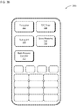
- FIG. 6 is an example illustration of a mobile device, such as a user equipment (UE), a mobile station (MS), a mobile wireless device, a mobile communication device, a tablet, a handset, or another type of wireless communication device.
- the mobile device can include one or more antennas configured to communicate with a transmission station, such as a base station (BS), an eNB, a base band unit (BBU), a remote radio head (RRH), a remote radio equipment (RRE), a relay station (RS), a radio equipment (RE), or another type of wireless wide area network (WWAN) access point.
- the mobile device can be configured to communicate using at least one wireless communication standard, including 3GPP LTE, WiMAX, high speed packet access (HSPA), Bluetooth, and Wi-Fi.
- the mobile device can communicate using separate antennas for each wireless communication standard or shared antennas for multiple wireless communication standards.
- the mobile device can communicate in a wireless local area network (WLAN), a wireless personal area network (WPAN), and/or a WWAN
- FIG. 6 also provides an illustration of a microphone and one or more speakers that can be used for audio input and output from the mobile device.
- the display screen may be a liquid crystal display (LCD) screen or other type of display screen, such as an organic light emitting diode (OLED) display.
- the display screen can be configured as a touch screen.
- the touch screen may use capacitive, resistive, or another type of touch screen technology.
- An application processor and a graphics processor can be coupled to internal memory to provide processing and display capabilities.
- a non-volatile memory port can also be used to provide data input/output options to a user.
- the non-volatile memory port may also be used to expand the memory capabilities of the mobile device.
- a keyboard may be integrated with the mobile device or wirelessly connected to the mobile device to provide additional user input.
- a virtual keyboard may also be provided using the touch screen.
- Example 1 is a UE configured to communicate with an eUTRAN.
- the UE includes a transceiver and a processor coupled to the transceiver.
- the processor is configured to receive a unicast message from the eUTRAN.
- the message includes parameters for a T310 timer and indicates which parameters to use for different UE speeds.
- the processor is also configured to determine a radio link with the eUTRAN has a quality below a predetermined threshold.
- the processor is also configured to determine a current speed of the UE.
- the processor is also configured to configure the T310 timer with the parameters for the current speed of the UE.
- the processor is also configured to start the T310 timer.
- the processor is also configured to declare a radio link failure when the T310 timer expires
- the parameters for the T310 timer of Example 1 include a scaling factor.
- the T310 timer is multiplied by the scaling factor to adjust a running time of the T310 timer.
- Example 3 the scaling factor of any of Examples 1-2 causes the T310 timer to take less time to expire when the current speed of the UE is less than a predetermined threshold.
- Example 4 the parameters for the T310 timer of any of Examples 1-3 include which of a short T310 timer and a long T310 timer to use as the T310 timer.
- Example 5 the processor of any of Examples 1-4 is configured to start the short timer when the current speed of the UE is less than a predetermined threshold.
- Example 6 the processor of any of Examples 1-5 is configured to determine the radio link is bad by generating a predetermined number of out-of-sync indications.
- Example 7 the UE of any of Examples 1-6 receives the indications of which T310 timer parameters to use in an RRC message.
- Example 8 the UE of any of Examples 1-7, includes a transceiver including transmitter and receiver components, multiple antennas, in which a first antenna of the multiple antennas is coupled to the transmitter, and in which a second antenna of the multiple antennas is coupled to the receiver, a display touchscreen, and a keyboard.
- Example 9 is a method for adjusting a time until a radio link failure is declared.
- the method includes receiving configuration information from a base station in a one-to-one message.
- the method also includes determining a speed of a mobile user device.
- the method also includes configuring a radio link failure timer based on the speed of the mobile user device and the configuration information. The radio link failure timer is longer when the mobile user device is moving at a high speed than it is when the mobile user device is moving at a low speed.
- Example 10 the method of Example 9 includes detecting a radio link quality below a predetermined threshold. The method also includes starting the radio link failure timer in response to detecting the radio link quality below the predetermined threshold. The method also includes declaring a radio link failure when the radio link failure timer expires.
- Example 11 the configuring of the radio link failure timer of any of Examples 9-10 includes determining which of a long timer and a short timer to use as the radio link failure timer.
- Example 12 the configuring of the radio link failure timer of any of Examples 9-11 includes selecting a scaling factor to adjust a run time of the radio link failure timer.
- Example 13 the determining the speed of the mobile user device of any of Examples 9-12 includes classifying the mobile user device into one of a plurality of states based on the speed of the mobile user device.
- Example 14 the receiving of configuration information of any of Examples 9-13 includes receiving configuration information associated with one or more of the plurality of states.
- Example 15 the method of any of Examples 9-14 includes transmitting indications of characteristics of the mobile user device to the base station.
- the configuration information is determined by the base station based on the indications of the characteristics.
- Example 16 is a device for adjusting a time until a radio link failure is declared.
- the device includes circuitry.
- the circuitry is configured to access settings for a recovery timer for each of a plurality of speed states of the device. The settings were indicated in a reconfiguration message from a based station.
- the circuitry is also configured to determine a current speed state of the device.
- the circuitry is also configured to, upon detecting a decline in signal quality, start the recovery timer according to the settings for the current speed state.
- Example 17 the circuitry of Example 16 is further configured to switch to an idle mode in response to the recovery timer expiring.
- Example 18 the settings for the recovery timer of any of Examples 16-17 include a scaling factor for the recovery timer for each of the plurality of speed states.
- Example 19 the scaling factor of any of Examples 16-18 decreases a running time of the recovery timer when the current speed state is a low speed state.
- Example 20 the settings for the recovery timer of any of Examples 16-19 include a running time for a short timer used in a low speed state and a running time for a long timer used in a high speed state.
- Example 21 the circuitry of any of Examples 16-20 is configured to start the short timer and the long timer upon detecting the decline in signal quality.
- the local transceiver is configured to determine, based on the current speed state, which of an expiration of the short time and an expiration of long timer should cause the local transceiver to declare a radio link failure.
- Example 22 the circuitry of any of Examples 16-21 is configured to provide identifying information to the base station. The settings are selected by the base station based on the identifying information.
- Example 23 is a method for adjusting a time until a radio link failure is declared when communicating with an eUTRAN.
- the method includes receiving, at a UE, a one-to-one message from an eNB.
- the message also includes parameters for a T310 timer and indicates which parameters to use for different UE speeds.
- the method also includes determining a radio link with the eNB has a quality below a predetermined threshold.
- the method also includes determining a current speed of the UE.
- the method also includes configuring the T310 timer with the parameters for the current speed of the UE.
- the method also includes starting the T310 timer.
- the method also includes declaring a radio link failure when the T310 timer expires.
- the parameters for the T310 timer of Example 23 include a scaling factor.
- Configuring the T310 timer includes multiplying the T310 timer by the scaling factor to adjust a running time of the T310 timer.
- Example 25 the scaling factor of any of Examples 23-24 causes the T310 timer to take less time to expire when the current speed of the UE is less than a predetermined threshold.
- the parameters for the T310 timer of any of Examples 23-25 include a running time of a short timer and a running time of a long timer.
- Configuring the T310 timer includes determining which of the long timer and the short timer to use as the T310 timer.
- Example 27 the determining of which of the long timer and the short timer to use of any of Examples 23-26 includes using the short timer when the speed of the UE is less than a predetermined threshold.
- Example 28 the determining that the radio link with the eNB has the quality below the predetermined threshold of any of Examples 23-27 includes generating a predetermined number of out-of-sync indications.
- Example 29 the receiving the one-to-one message of any of Example 23-28 includes receiving an RRC message.
- Example 30 the determining of the current speed of the UE of any of Examples 23-29 includes classifying UE into one of a plurality of states based on the speed of the UE.
- Example 31 the receiving of the one-to-one message including the parameters for the T310 timer of any of Examples 23-30 includes receiving parameters associated with one or more of the plurality of states.
- Example 32 the method of any of Examples 23-31 includes transmitting indications of characteristics of the UE to the eNB.
- the parameters for the T310 timer are determined by the eNB based on the indications of the characteristics.
- Various techniques, or certain aspects or portions thereof, may take the form of program code (i.e., instructions) embodied in tangible media, such as floppy diskettes, CD-ROMs, hard drives, a non-transitory computer readable storage medium, or any other machine-readable storage medium, wherein, when the program code is loaded into and executed by a machine, such as a computer, the machine becomes an apparatus for practicing the various techniques.
- the computing device may include a processor, a storage medium readable by the processor (including volatile and non-volatile memory and/or storage elements), at least one input device, and at least one output device.
- the volatile and non-volatile memory and/or storage elements may be a RAM, an EPROM, a flash drive, an optical drive, a magnetic hard drive, or another medium for storing electronic data.
- the eNB (or other base station) and UE (or other mobile station) may also include a transceiver component, a counter component, a processing component, and/or a clock component or timer component.
- One or more programs that may implement or utilize the various techniques described herein may use an application programming interface (API), reusable controls, and the like. Such programs may be implemented in a high-level procedural or an object-oriented programming language to communicate with a computer system. However, the program(s) may be implemented in assembly or machine language, if desired. In any case, the language may be a compiled or interpreted language, and combined with hardware implementations.
- a component may be implemented as a hardware circuit comprising custom very large scale integration (VLSI) circuits or gate arrays, off-the-shelf semiconductors such as logic chips, transistors, or other discrete components.
- VLSI very large scale integration
- a component may also be implemented in programmable hardware devices such as field programmable gate arrays, programmable array logic, programmable logic devices, or the like.
- Components may also be implemented in software for execution by various types of processors.
- An identified component of executable code may, for instance, comprise one or more physical or logical blocks of computer instructions, which may, for instance, be organized as an object, a procedure, or a function. Nevertheless, the executables of an identified component need not be physically located together, but may comprise disparate instructions stored in different locations that, when joined logically together, comprise the component and achieve the stated purpose for the component.
- a component of executable code may be a single instruction, or many instructions, and may even be distributed over several different code segments, among different programs, and across several memory devices.
- operational data may be identified and illustrated herein within components, and may be embodied in any suitable form and organized within any suitable type of data structure. The operational data may be collected as a single data set, or may be distributed over different locations including over different storage devices, and may exist, at least partially, merely as electronic signals on a system or network.
- the components may be passive or active, including agents operable to perform desired functions.
Landscapes
- Engineering & Computer Science (AREA)
- Signal Processing (AREA)
- Computer Networks & Wireless Communication (AREA)
- Theoretical Computer Science (AREA)
- Software Systems (AREA)
- Databases & Information Systems (AREA)
- Physics & Mathematics (AREA)
- Quality & Reliability (AREA)
- Computer Security & Cryptography (AREA)
- General Engineering & Computer Science (AREA)
- General Physics & Mathematics (AREA)
- Mathematical Physics (AREA)
- Mobile Radio Communication Systems (AREA)
- Information Transfer Between Computers (AREA)
- Telephone Function (AREA)
Description
- The present disclosure relates to systems, methods, and devices for providing different radio link failure timers based on the speed of user equipment.
- 3GPP Tdoc. R2-132027, "Reduce Service Interruption Time with Adaptive RLF Trigger in HetNets", 3GPP TSG RAN WG2 Meeting #82, May 2013 discusses the impact of RLF trigger (T310) setting on the mobility performance and signaling in HetNets for different scenarios and discussed the possibility to optimize the T310 setting for different scenarios therefore to improve the mobility performance in terms of reducing the RLF rate and minimizing the time of service interruption.
-
US 20120088498 A1 relates to an automated coverage hole detection (CHD) method based on modifying the setting of a specific parameter of a UE in, e.g., an LTE-based cellular wireless network. Physical RLF events of the UEs, possibly indicative of a coverage hole, are monitored. At least some of the UEs in a given cell are selected for modifying their parameter setting. For UEs that do not have advanced logging and reporting capabilities upon the physical RLF, the existence of a coverage hole is detected by analyzing the correlation between the settings of a timer and the probability for the UE to transit to RRC_IDLE mode. The settings of the timer are systematically adjusted via eNB signalling to evaluate the characteristics of the observed RLFs. - The invention is defined by the independent claims. Advantageous embodiments are subject to the dependent claims.
-
-
Figure 1 is a schematic diagram of a system including a plurality of UEs moving at various speeds connected to a radio access network. -
Figure 2 is a schematic diagram of UE performance during a radio link failure for different RLF timer speeds. -
Figure 3A is a schematic diagram of a UE configured to provide a plurality of different T310 timers based on UE speed. -
Figure 3B is a schematic diagram of a UE configured to adjust a T310 timer speed based on UE speed. -
Figure 4 is a flow diagram of a method for receiving information on T310 timer speeds. -
Figure 5 is a flow diagram of a method for determining whether to declare a radio link failure. -
Figure 6 is a schematic diagram of a UE able to support modified T310 timers. - Wireless mobile communication technology uses various standards and protocols to transmit data between a base station and a wireless communication device. Wireless communication system standards and protocols can include, for example, the 3rd Generation Partnership Project (3GPP) long term evolution (LTE); the Institute of Electrical and Electronics Engineers (IEEE) 802.16 standard, which is commonly known to industry groups as worldwide interoperability for microwave access (WiMAX); and the IEEE 802.11 standard, which is commonly known to industry groups as Wi-Fi. In 3GPP radio access networks (RANs) in LTE systems, a base station may include Evolved Universal Terrestrial Radio Access Network (E-UTRAN) Node Bs (also commonly denoted as evolved Node Bs, enhanced Node Bs, eNodeBs, or eNBs) and/or Radio Network Controllers (RNCs) in an E-UTRAN, which communicate with a wireless communication device, known as user equipment (UE). An evolved packet core (EPC) may communicatively couple the E-UTRAN to an external network, such as the Internet.
- LTE networks include radio access technology and core radio network architecture that provide high data rate, low latency, packet optimization, and improved system capacity and coverage. In LTE networks, an E-UTRAN may include a plurality of eNodeBs and may communicate with a plurality of UEs. UEs may be handed over from one eNodeB to another as the signal strength of the eNodeBs changes (e.g., due to movement by the UEs). A UE may start a radio link failure (RLF) timer (e.g., a T310 timer, a recover timer, or the like) if the signal quality from an eNodeB to which the UE is currently connected falls below a predetermined threshold. For example, if a Channel Quality Indicator (CQI) is less than a threshold Qout, an out-of-sync indication may be generated. If more than a specified number of out-of-sync indications are received, the RLF timer may be started. If the CQI is greater than a threshold Qin more than a specified number of times, the RLF timer may be stopped. If the RLF timer expires, an RLF may be declared. RLFs may occur during handover or when a handover is not occurring but may be more prevalent during handovers. If an RLF is declared, the UE may attempt to establish a connection with an eNodeB that has the UE context and/or may enter an idle mode and restart the connection process a new.
- The plurality of UEs may travel at different speeds relative to the eNodeBs. For example, one UE may be carried by a person who is stationary or travelling on foot and another may be carried by a person travelling in a car or a high speed train. The channel conditions experienced by the UEs may be different. The channel condition may change quickly for the rapidly moving UE, and the UE may quickly distance itself from any sources of interference that begin degrading the channel. If given enough time, the UE may be able to recover a radio link with the eNodeB without declaring an RLF. In contrast, the slowly moving UE may be less likely to recover from poor channel conditions. Shadowing and/or a source of interference may degrade performance of the UE for an extended period of time. The UE may receive an improved signal by changing to another eNodeB. Thus, performance of the slowly moving UE may be improved by declaring an RLF sooner and restarting the connection establishment process.
- The time until an RLF is declared may be adjusted for each UE to accommodate the different speeds of the various UEs. In some embodiments, the UE determines the speed at which it is moving and adjusts the RLF timer parameters accordingly. The running time of the RLF timer may be increased for rapidly moving UEs, may be decreased for slowly moving UEs, and/or the like. The UE may determine the RLF timer parameters for a plurality of speeds in advance and may select the RLF timer parameters corresponding to a current speed when the RLF timer needs to be started. Alternatively, only the RLF parameters for the current speed may be determined. The UE may be classified into one of a plurality speed states based on the speed of the UE. The speed states may include slow, medium, and/or fast. There may be 2, 3, 4, 5, or more speed states. The speeds corresponding to each speed states may be predefined and/or may be communicated to the UE by the eNodeB.
- The UE adjusts the RLF timer parameters by determining which of a plurality of scaling factors should be applied to the RLF timer. A scaling factor that causes the RLF timer to expire sooner or does not change the RLF timer may be used for a slowly moving UE. A scaling factor that does not change the RLF timer or that causes the RLF timer to expire later may be used for a rapidly moving UE. In an embodiment, a scaling factor less than one causes the timer to count up more slowly. The UE may adjust the RLF timer parameters by determining which of a plurality of RLF timers to use to determine when to declare an RLF. The plurality of RLF timers may be configured to run for different lengths of time before expiring. The plurality of RLF timers may all be started and only the RLF timer corresponding to the current UE speed may be evaluated when determining whether to declare an RLF. Alternatively, only the RLF timer corresponding to the current UE speed may be started. In an embodiment, a long RLF timer may be used by a rapidly moving UE, and a short RLF timer may be used by a slowly moving UE.
- The UE may receive the RLF timer parameters from an eNodeB. According to the invention, the RLF parameters include scaling factors to be used for different speed states. Optionally, the RLF parameters may further include a run time of the T310 timer, run times for a plurality of T310 timers (e.g., a long T310 timer and a short T310 timer), cutoffs for speed states, and/or the like. In one example implementation, the eNodeB may determine the speed of the UE and send a T310 timer value determined based on the UE speed to the UE. However, the eNodeB uses a lot of resources (e.g., storage resources, processing resources, communication resources, etc.) determining the speed of all connected UEs, tracking the speed, and sending updates to the T310 timer value. Resources can be saved by determining the UE speed only once, but the UE may use a non-optimal T310 timer value if it changes speed. In another embodiment, the eNodeB may broadcast a high speed timer value and a low speed timer value in a system information block (SIB), and the UE may determine which timer value to use based on its measurements of its own speed. However, there may be a large communication resource penalty when the system information block is made longer. Additionally, the eNodeB may not be able to customize timer parameters to individual UEs. In an embodiment of the invention, the eNodeB use a radio resource control (RRC) message (e.g., a connection reconfiguration message) to send timer parameters to the UE. For example,
SIB may include default timer parameters that do not account for speed, and the RRC message may further define the timer parameters for different speeds and/or speed states of the UE. The RRC message may be sent after the UE first attaches to the eNodeB. The RRC message may contain sufficient information for the UE to be able to determine which RLF timer parameters to use based on the UE's own determination of its speed. Accordingly, the eNodeB may not need to determine or track UE speed or send multiple RRC messages. The RRC message may be a unicast message sent in a one-to-one communication from the eNodeB to the UE and may only need to be sent once, so few communication resources may be used. In addition, the RLF timer parameters may be customized to the UE. For example, the UE may send indications of characteristics, such as identifying information for the UE, to the eNodeB. The characteristics may include a manufacturer of the UE, a model of the UE, settings of the UE, a manufacturer of a transceiver, a model of the transceiver, settings of the transceiver, an initial speed of the UE when first becoming attached, and/or the like. The eNodeB may determine the RLF timer parameters based on the received indications. The eNodeB may further determine the RLF timer parameters based on its own known characteristics (e.g., whether the eNodeB is urban or rural, the presence of shadowing objects, a number of pico cells or other small cells nearby, a number of UEs typically present, etc.). The eNodeB may attempt to optimize the RLF timer based on the expected performance of the UE under expected conditions for the different speeds. -
Figure 1 is a schematic diagram of asystem 100 comprising a plurality ofUEs eNodeB 110. TheUEs eNodeB 110. For example, afirst UE 120 may be held by a person and thus move slowly or not at all. Asecond UE 130 may be integrated into a vehicle and/or may be transported by a vehicle and thus move rapidly. The first andsecond UEs first UE 120 may experience slow fading. If a source of interference, shadowing, etc. is present, it may remain so for an extended period of time. Thesecond UE 130 may experience fast fading. Sources of interference may quickly enter and exit the range of thesecond UE 130. Because theUEs -
Figure 2 is a schematic diagram 200 of UE performance during a radio link failure for different RLF timer speeds. In an embodiment, the UE may detect that the CQI is less than the threshold Qout and generate an out-of-sync indication. Once N310 out-of-sync indications have been generated, the UE may start the T310 timer and attempt to recover the radio link. An in-sync indication may be generated if CQI is greater than the threshold Qin, and the T310 timer may reset if more than N311 in-sync indications are received. If the radio link is not recovered before the T310 timer expires (e.g., not more than N311 in-sync indications are received), a radio link failure may be declared. The UE may attempt to reestablish the connection and/or may enter idle mode once the radio link failure is declared. - A slowly moving UE may experience a
bad link condition 201 that lasts for an extended period of time. The slowly moving UE may need to establish a connection with a new eNodeB to resolve thebad link condition 201. In a longRLF timer situation 210, the slowly moving UE may have to wait an extended period of time for the RLF timer to expire before it can establish the connection with the new eNodeB. In the shortRLF timer situation 220, the slowly moving UE does not need to wait as long for the RLF timer to expire and may connect to the new eNodeB sooner. The UE will spend less time disconnected and provide a better user experience in the short RLF timer situation. - A rapidly moving UE may experience a
bad link condition 202 that lasts for a brief period of time. The rapidly moving UE may be able to recover its connection with the current eNodeB if enough time is allowed for thebad link condition 202 to pass. In a longRLF timer situation 230, the rapidly moving UE may have sufficient time to recover the connection with the current eNodeB after thebad link condition 202 has passed. In a shortRLF timer situation 240, the RLF timer may expire before thebad link condition 202 has passed and/or before the connection could be recovered. The UE will recover faster and provide a better user experience in the long RLF timer situation. - If the extended
bad link condition 201 is the most likely kind of bad link condition to occur for the slowly moving UE and the briefbad link condition 202 is the most like kind to occur for the rapidly moving UE, the average performance of the UEs over time will be best when a short timer is used for slowly moving UEs and a long timer is used for rapidly moving UEs. For many UEs, their speed may change over time in an unpredictable manner. Accordingly, the speed of the UE may be measured to determine which link conditions it is likely to experience and thus how long the RLF timer should operate. -
Figure 3A is a schematic diagram of an example implementation ofaUE 300a configured to provide a plurality of different T310 timers based on UE speed. TheUE 300a may include atransceiver 302 configured to communicatively couple theUE 300a to an eNodeB (not shown). Thetransceiver 302 may, inter alia, implement the physical layer and/or data link layer of the UE for communicating with the eNodeB. TheUE 300a may further include along T310 timer 304 and ashort T310 timer 306. Thetimers timers timer UE 300a may be able to change the run times depending on which eNodeB theUE 300a is connected to. For example, an urban eNodeB may expect different channel characteristics than a rural eNodeB, so theUE 300a may use different timer lengths for the different eNodeBs. - The
UE 300a may further include aspeed measuring unit 308. Thespeed measuring unit 308 may estimate how fast theUE 300a is travelling. Thespeed measuring unit 308 may determine speed based on a number, size, and/or location of cells traversed, based on a Doppler shift, based on a satellite navigation system, and/or the like. It is anticipated that further advances will be made in methods for estimating speed, and any such method may be used by thespeed measuring unit 308 to determine speed. Any units may be used by thespeed measuring unit 308 to express the speed, or thespeed measuring unit 308 may classify the speed as belonging to one of a plurality of speed states. The speed states may be defined based on a set of thresholds, and the appropriate speed state may be determined by comparing the measured speed to the set of thresholds. - The
UE 300a may include aradio resource controller 310, which may control RLF analysis and handovers between eNodeBs for theUE 300a. Theradio resource controller 310 may transmit characteristics of theUE 300a to the eNodeB and may receive back parameters for theT310 timers radio resource controller 310 in an RRC message. Theradio resource controller 310 may parse the RRC message and may configure theT310 timers radio resource controller 310 may receive the speed and/or speed state of theUE 300a from thespeed measuring unit 308 and determine whichT310 timer radio resource controller 310 may start one or both of theT310 timers appropriate T310 timer transceiver 302,T310 timers speed measuring unit 308, andradio resource controller 310 are illustrated as separate units, the functionalities may be combined into fewer units and/or further separated into additional units in other embodiments.
Figure 3B is a schematic diagram of an embodiment of aUE 300b configured to adjust a T310 timer speed based on UE speed. TheUE 300b may include atransceiver 302, which may be substantially similar to thetransceiver 302 of theUE 300a. Additionally, theUEs units 308 that are substantially similar to one another. Rather than having twoT310 timers UE 300b may include asingle T310 timer 314. TheT310 timer 314 may be adjusted by ascaling unit 316 to account for variations in speed of theUE 300b. TheUE 300b may also include a radio resource controller 320. The radio resource controller 320 may be similar to theradio resource controller 310, but the radio resource controller 320 may control theT310 timer 314 and thescaling unit 316 rather than the twoT310 timers - In response to sending characteristic information to the eNodeB, the radio resource controller 320 may receive scaling unit parameters for one or more speeds and/or speed states. In an embodiment, one speed state may use a default scaling, so only the other speed state(s) may need scaling unit parameters. The radio resource controller 320 may receive the speed and/or speed state from the
speed measuring unit 308 and may instruct thescaling unit 316 to use a particular scaling factor based on the speed and/or speed state. TheT310 timer 314 may count up to a specified threshold and/or count down from a specified starting point. Thescaling unit 316 may be configured based on the design of theT310 timer 314. The scaling factor may be multiplied by the specified threshold, the specified starting point, the current count of the T310 timer 312, and/or the like. The radio resource controller 320 may determine when the scaled T310 timer has expired and may declare an RLF when the scaled T310 timer has expired. Although thetransceiver 302,T310 timer 314, scalingunit 316,speed measuring unit 308, and radio resource controller 320 are illustrated as separate units, the functionalities may be combined into fewer units and/or further separated into additional units in other embodiments. -
Figure 4 is a flow diagram of amethod 400 for receiving information on T310 timer speeds. Themethod 400 may begin with an eNodeB being detected 402, for example, by a UE. The eNodeB may be detected as a result of the UE first being turned on, as a part of a normal handoff procedure, and/or the like. The UE may request 404 attachment to the detected eNodeB. For example, the UE may transmit a connection request to the detected eNodeB, and/or a handover request may be sent on the UE's behalf. - During and/or after attachment, characteristics of the UE may be provided 406 to the eNodeB. For example, identifying information for the UE (e.g., a manufacturer of the UE, a model of the UE, etc.), settings of the UE, a manufacturer of a transceiver, a model of the transceiver, settings of the transceiver, an initial speed of the UE, and/or the like may be provided to the eNodeB. The eNodeB may request the information it wants, and/or a predetermined set of information may be provided to the eNodeB. Based on the provided information about the UE and/or already known information about the eNodeB, the eNodeB may determine T310 timer parameters. An RRC message containing the T310 timer parameters may be received 408 from the eNodeB. For example, the RRC message may be a connection reconfiguration message. Depending on the embodiment and/or configuration, the T310 parameters may include run times for a short timer and a long timer, scaling factors for different speeds, and/or the like. The T310 timer parameters may include speed divisions and/or definitions of speed states that indicate which timer and/or scaling factor should be used for each UE speed.
- The T310 timer may be configured 410 based on the T310 timer parameters received in the RRC message. Configuring 410 the T310 timer parameters may include configuring the T310 timer to operate using the parameters for the current UE speed. The UE speed may be continually monitored, and the parameters may be updated as the UE speed changes. Alternatively, or in addition, the T310 timer may be configured with all the received parameters, and the particular parameters to be used may be determined based on the UE speed when the T310 timer is needed.
-
Figure 5 is a flow diagram of amethod 500 for determining whether to declare a radio link failure. Themethod 500 may begin when a bad radio link is detected 502. Detecting 502 the bad radio link may include determining whether the CQI is less than a threshold Qout and generating an out-of-sync indication. Detecting 502 the bad radio link may further include determining that more than a specified number of out-of-sync indications have been generated (e.g., more than a number N310 specified by an eNodeB). If more than the specified number of out-of-sync indications have been generated, it may be determined that the radio link is bad. Otherwise, the CQI may continue to be monitored. - In an embodiment, the UE speed may be determined 504 in response to the bad radio link being detected 502. Alternatively, or in addition, the UE speed may have previously determined and may not need to be determined again. Determining 504 the UE speed may include retrieving a continually updated UE speed. The UE speed may be in any of various units, and/or the UE speed may be specified as a speed state. For example, one embodiment may include UE speed states of fast and slow, and another embodiment may include UE speed states of fast, medium, and slow. The speeds corresponding to each speed state may be specified by the eNodeB, predetermined, defined by a standard, and/or the like. The parameters for the T310 timer may be selected 506 based on the UE speed determined 504. Selecting 506 the parameters may include determining which of a plurality of T310 timers to use, determining a scaling factor for the T310 timer, determining a run time for the T310 timer, and/or the like. In some embodiments, the parameters for the T310 timer may have been determined previously, for example, when a UE speed was previously measured. In such embodiments, the T310 timer parameters may not need to be selected 506 again.
- Once the T310 timer parameters have been selected and the T310 timer has been configured, the T310 timer may be started 508. The T310 timer may count down from a specified starting point, may count up to a specified threshold, and/or the like. The T310 timer may continue to operate as long as fewer than a specified number of in-sync indications have been received. For example, an in-sync indication may be generated each time the CQI is greater than a threshold Qin. If more than the specified number of in-sync indications are received, then it may be assumed that the radio link has recovered. The T310 timer may be stopped and reset until the next bad radio link is detected 502. If the radio link is not recovered, the T310 timer may run until it expires. The T310 timer may expire by counting down to zero or by counting up to the specified threshold. A radio link failure may be declared 510 if the T310 timer expires. In response to the radio link failure, the UE may attempt to reestablish a connection with the eNodeB and/or may go to idle mode and start the connection process over again.
-
Figure 6 is an example illustration of a mobile device, such as a user equipment (UE), a mobile station (MS), a mobile wireless device, a mobile communication device, a tablet, a handset, or another type of wireless communication device. The mobile device can include one or more antennas configured to communicate with a transmission station, such as a base station (BS), an eNB, a base band unit (BBU), a remote radio head (RRH), a remote radio equipment (RRE), a relay station (RS), a radio equipment (RE), or another type of wireless wide area network (WWAN) access point. The mobile device can be configured to communicate using at least one wireless communication standard, including 3GPP LTE, WiMAX, high speed packet access (HSPA), Bluetooth, and Wi-Fi. The mobile device can communicate using separate antennas for each wireless communication standard or shared antennas for multiple wireless communication standards. The mobile device can communicate in a wireless local area network (WLAN), a wireless personal area network (WPAN), and/or a WWAN. -
Figure 6 also provides an illustration of a microphone and one or more speakers that can be used for audio input and output from the mobile device. The display screen may be a liquid crystal display (LCD) screen or other type of display screen, such as an organic light emitting diode (OLED) display. The display screen can be configured as a touch screen. The touch screen may use capacitive, resistive, or another type of touch screen technology. An application processor and a graphics processor can be coupled to internal memory to provide processing and display capabilities. A non-volatile memory port can also be used to provide data input/output options to a user. The non-volatile memory port may also be used to expand the memory capabilities of the mobile device. A keyboard may be integrated with the mobile device or wirelessly connected to the mobile device to provide additional user input. A virtual keyboard may also be provided using the touch screen. - Example 1 is a UE configured to communicate with an eUTRAN. The UE includes a transceiver and a processor coupled to the transceiver. The processor is configured to receive a unicast message from the eUTRAN. The message includes parameters for a T310 timer and indicates which parameters to use for different UE speeds. The processor is also configured to determine a radio link with the eUTRAN has a quality below a predetermined threshold. The processor is also configured to determine a current speed of the UE. The processor is also configured to configure the T310 timer with the parameters for the current speed of the UE. The processor is also configured to start the T310 timer. The processor is also configured to declare a radio link failure when the T310 timer expires
- In Example 2, the parameters for the T310 timer of Example 1 include a scaling factor. The T310 timer is multiplied by the scaling factor to adjust a running time of the T310 timer.
- In Example 3, the scaling factor of any of Examples 1-2 causes the T310 timer to take less time to expire when the current speed of the UE is less than a predetermined threshold.
- In Example 4, the parameters for the T310 timer of any of Examples 1-3 include which of a short T310 timer and a long T310 timer to use as the T310 timer.
- In Example 5, the processor of any of Examples 1-4 is configured to start the short timer when the current speed of the UE is less than a predetermined threshold.
- In Example 6, the processor of any of Examples 1-5 is configured to determine the radio link is bad by generating a predetermined number of out-of-sync indications.
- In Example 7, the UE of any of Examples 1-6 receives the indications of which T310 timer parameters to use in an RRC message.
- In Example 8, the UE of any of Examples 1-7, includes a transceiver including transmitter and receiver components, multiple antennas, in which a first antenna of the multiple antennas is coupled to the transmitter, and in which a second antenna of the multiple antennas is coupled to the receiver, a display touchscreen, and a keyboard.
- Example 9 is a method for adjusting a time until a radio link failure is declared. The method includes receiving configuration information from a base station in a one-to-one message. The method also includes determining a speed of a mobile user device. The method also includes configuring a radio link failure timer based on the speed of the mobile user device and the configuration information. The radio link failure timer is longer when the mobile user device is moving at a high speed than it is when the mobile user device is moving at a low speed.
- In Example 10, the method of Example 9 includes detecting a radio link quality below a predetermined threshold. The method also includes starting the radio link failure timer in response to detecting the radio link quality below the predetermined threshold. The method also includes declaring a radio link failure when the radio link failure timer expires.
- In Example 11, the configuring of the radio link failure timer of any of Examples 9-10 includes determining which of a long timer and a short timer to use as the radio link failure timer.
- In Example 12, the configuring of the radio link failure timer of any of Examples 9-11 includes selecting a scaling factor to adjust a run time of the radio link failure timer.
- In Example 13, the determining the speed of the mobile user device of any of Examples 9-12 includes classifying the mobile user device into one of a plurality of states based on the speed of the mobile user device.
- In Example 14, the receiving of configuration information of any of Examples 9-13 includes receiving configuration information associated with one or more of the plurality of states.
- In Example 15, the method of any of Examples 9-14 includes transmitting indications of characteristics of the mobile user device to the base station. The configuration information is determined by the base station based on the indications of the characteristics.
- Example 16 is a device for adjusting a time until a radio link failure is declared. The device includes circuitry. The circuitry is configured to access settings for a recovery timer for each of a plurality of speed states of the device. The settings were indicated in a reconfiguration message from a based station. The circuitry is also configured to determine a current speed state of the device. The circuitry is also configured to, upon detecting a decline in signal quality, start the recovery timer according to the settings for the current speed state.
- In Example 17, the circuitry of Example 16 is further configured to switch to an idle mode in response to the recovery timer expiring.
- In Example 18, the settings for the recovery timer of any of Examples 16-17 include a scaling factor for the recovery timer for each of the plurality of speed states.
- In Example 19, the scaling factor of any of Examples 16-18 decreases a running time of the recovery timer when the current speed state is a low speed state.
- In Example 20, the settings for the recovery timer of any of Examples 16-19 include a running time for a short timer used in a low speed state and a running time for a long timer used in a high speed state.
- In Example 21, the circuitry of any of Examples 16-20 is configured to start the short timer and the long timer upon detecting the decline in signal quality. The local transceiver is configured to determine, based on the current speed state, which of an expiration of the short time and an expiration of long timer should cause the local transceiver to declare a radio link failure.
- In Example 22, the circuitry of any of Examples 16-21 is configured to provide identifying information to the base station. The settings are selected by the base station based on the identifying information.
- Example 23 is a method for adjusting a time until a radio link failure is declared when communicating with an eUTRAN. The method includes receiving, at a UE, a one-to-one message from an eNB. The message also includes parameters for a T310 timer and indicates which parameters to use for different UE speeds. The method also includes determining a radio link with the eNB has a quality below a predetermined threshold. The method also includes determining a current speed of the UE. The method also includes configuring the T310 timer with the parameters for the current speed of the UE. The method also includes starting the T310 timer. The method also includes declaring a radio link failure when the T310 timer expires.
- In Example 24, the parameters for the T310 timer of Example 23 include a scaling factor. Configuring the T310 timer includes multiplying the T310 timer by the scaling factor to adjust a running time of the T310 timer.
- In Example 25, the scaling factor of any of Examples 23-24 causes the T310 timer to take less time to expire when the current speed of the UE is less than a predetermined threshold.
- In Example 26, the parameters for the T310 timer of any of Examples 23-25 include a running time of a short timer and a running time of a long timer. Configuring the T310 timer includes determining which of the long timer and the short timer to use as the T310 timer.
- In Example, 27, the determining of which of the long timer and the short timer to use of any of Examples 23-26 includes using the short timer when the speed of the UE is less than a predetermined threshold.
- In Example 28, the determining that the radio link with the eNB has the quality below the predetermined threshold of any of Examples 23-27 includes generating a predetermined number of out-of-sync indications.
- In Example 29, the receiving the one-to-one message of any of Example 23-28 includes receiving an RRC message.
- In Example 30, the determining of the current speed of the UE of any of Examples 23-29 includes classifying UE into one of a plurality of states based on the speed of the UE.
- In Example 31, the receiving of the one-to-one message including the parameters for the T310 timer of any of Examples 23-30 includes receiving parameters associated with one or more of the plurality of states.
- In Example 32, the method of any of Examples 23-31 includes transmitting indications of characteristics of the UE to the eNB. The parameters for the T310 timer are determined by the eNB based on the indications of the characteristics.
- Various techniques, or certain aspects or portions thereof, may take the form of program code (i.e., instructions) embodied in tangible media, such as floppy diskettes, CD-ROMs, hard drives, a non-transitory computer readable storage medium, or any other machine-readable storage medium, wherein, when the program code is loaded into and executed by a machine, such as a computer, the machine becomes an apparatus for practicing the various techniques. In the case of program code execution on programmable computers, the computing device may include a processor, a storage medium readable by the processor (including volatile and non-volatile memory and/or storage elements), at least one input device, and at least one output device. The volatile and non-volatile memory and/or storage elements may be a RAM, an EPROM, a flash drive, an optical drive, a magnetic hard drive, or another medium for storing electronic data. The eNB (or other base station) and UE (or other mobile station) may also include a transceiver component, a counter component, a processing component, and/or a clock component or timer component. One or more programs that may implement or utilize the various techniques described herein may use an application programming interface (API), reusable controls, and the like. Such programs may be implemented in a high-level procedural or an object-oriented programming language to communicate with a computer system. However, the program(s) may be implemented in assembly or machine language, if desired. In any case, the language may be a compiled or interpreted language, and combined with hardware implementations.
- It should be understood that many of the functional units described in this specification may be implemented as one or more components, which is a term used to more particularly emphasize their implementation independence. For example, a component may be implemented as a hardware circuit comprising custom very large scale integration (VLSI) circuits or gate arrays, off-the-shelf semiconductors such as logic chips, transistors, or other discrete components. A component may also be implemented in programmable hardware devices such as field programmable gate arrays, programmable array logic, programmable logic devices, or the like.
- Components may also be implemented in software for execution by various types of processors. An identified component of executable code may, for instance, comprise one or more physical or logical blocks of computer instructions, which may, for instance, be organized as an object, a procedure, or a function. Nevertheless, the executables of an identified component need not be physically located together, but may comprise disparate instructions stored in different locations that, when joined logically together, comprise the component and achieve the stated purpose for the component.
- Indeed, a component of executable code may be a single instruction, or many instructions, and may even be distributed over several different code segments, among different programs, and across several memory devices. Similarly, operational data may be identified and illustrated herein within components, and may be embodied in any suitable form and organized within any suitable type of data structure. The operational data may be collected as a single data set, or may be distributed over different locations including over different storage devices, and may exist, at least partially, merely as electronic signals on a system or network. The components may be passive or active, including agents operable to perform desired functions.
- Reference throughout this specification to "an example" means that a particular feature, structure, or characteristic described in connection with the example is included in at least one embodiment of the present disclosure. Thus, appearances of the phrase "in an example" in various places throughout this specification are not necessarily all referring to the same embodiment.
- As used herein, a plurality of items, structural elements, compositional elements, and/or materials may be presented in a common list for convenience. However, these lists should be construed as though each member of the list is individually identified as a separate and unique member. Thus, no individual member of such list should be construed as a de facto equivalent of any other member of the same list solely based on its presentation in a common group without indications to the contrary. In addition, various embodiments and examples of the present disclosure may be referred to herein along with alternatives for the various components thereof. It is understood that such embodiments, examples, and alternatives are not to be construed as de facto equivalents of one another, but are to be considered as separate and autonomous representations of the present disclosure.
It is understood that such embodiments, examples, and alternatives are not to be construed as de facto equivalents of one another, but are to be considered as separate and autonomous representations of the present disclosure. - Although the foregoing has been described in some detail for purposes of clarity, it will be apparent that certain changes and modifications may be made without departing from the principles thereof. It should be noted that there are many alternative ways of implementing both the processes and apparatuses described herein. Accordingly, the present embodiments are to be considered illustrative and not restrictive, and the disclosure is not to be limited to the details given herein, but may be modified within the scope and equivalents of the appended claims.
- Those having skill in the art will appreciate that many changes may be made to the details of the above-described embodiments without departing from the underlying principles of the disclosure. The scope of the present application should, therefore, be determined only by the following claims.
Claims (8)
- A user equipment (no, 120, 300a, 300b) configured to communicate with an evolved universal terrestrial radio access network, eUTRAN (110), the user equipment (110, 120, 300a, 300b) comprising:a transceiver (302); anda processor coupled to the transceiver (302), the processor configured to:determine a radio link with the eUTRAN (110) has a quality below a predetermined threshold;determine a current speed of the user equipment (110, 120, 300a, 300b); configure a T310 timer (314);start the T310 timer (314) in response to determining the radio link with eUTRAN has quality below a predetermined threshold; and declare a radio link failure when the T310 timer (314) expires; wherein the processor is further configured to:receive a unicast message from the eUTRAN (110), the message comprising parameters for the T310 timer (314) and indicating which parameters to use for different user equipment speeds;configure the T310 timer (314) with the parameters for the current speed of the user equipment (110, 120, 300a, 300b) comprised in said unicast message;wherein the parameters for the T310 timer (314) include a scaling factor, and wherein the T310 timer (314) is multiplied by the scaling factor to adjust a running time of the T310 timer (314); andwherein the scaling factor causes the T310 timer (314) to take less time to expire when the current speed of the user equipment (110, 120, 300a, 300b) is less than a predetermined threshold.
- The user equipment (110, 120, 300a, 300b) of claim 1, wherein the processor is configured to determine the radio link is bad by generating a predetermined number of out-of-sync indications.
- The user equipment (110, 120, 300a, 300b) of claim 1 or 2, wherein the user equipment (110, 120, 300a, 300b) receives the indications of which T310 timer (314) parameters to use in a RRC message.
- The user equipment (110, 120, 300a, 300b) of one of claims 1 to 3, further comprising:a transceiver (302) including transmitter and receiver components;multiple antennas, in which a first antenna of the multiple antennas is coupled to the transmitter, and in which a second antenna of the multiple antennas is coupled to the receiver;a display touchscreen; anda keyboard.
- A method for adjusting a time until a radio link failure is declared, the method comprising:determining a speed of a mobile user device (110, 120, 300a, 300b); andconfiguring a radio link failure timer (314) based on the speed of the mobile user device (110, 120, 300a, 300b);detecting a radio link quality below a predetermined threshold;starting the radio link failure timer (314) in response to detecting the radio link quality below the predetermined threshold; anddeclaring a radio link failure when the radio link failure timer expires;receiving a unicast message from the eUTRAN (110), the message comprising parameters for the radio link failure timer (314) and indicating which parameters to use for different mobile user device speeds;wherein the radio link failure timer (314) is configured with the parameters for the current speed of the mobile user device (110, 120, 300a, 300b) comprised in said unicast message;wherein the parameters for the radio link failure timer (314) include a scaling factor, and wherein the timer (314) is multiplied by the scaling factor to adjust a running time of the timer (314); andwherein the scaling factor causes the radio link failure timer (314) to take less time to expire when the current speed of the mobile user device (110, 120, 300a, 300b) is less than a predetermined threshold.
- The method of claim 5, wherein configuring the radio link failure timer comprises selecting a scaling factor to adjust a run time of the radio link failure timer (314).
- The method of claim 5 or 6, wherein determining the speed of the mobile user device (110, 120, 300a, 300b) comprises classifying the mobile user device (110, 120, 300a, 300b)into one of a plurality of states based on the speed of the mobile user device (110, 120, 300a, 300b).
- A machine readable medium storing instructions that, when executed by a processor of a user equipment (110, 120, 300a, 300b), cause the user equipment (110, 120, 300a, 300b) to perform the method of one of claims 5-7.
Applications Claiming Priority (3)
| Application Number | Priority Date | Filing Date | Title |
|---|---|---|---|
| US201361883127P | 2013-09-26 | 2013-09-26 | |
| US14/317,184 US9258723B2 (en) | 2013-09-26 | 2014-06-27 | Systems, methods, and devices with different radio link failure timers based on user equipment speed |
| PCT/US2014/050731 WO2015047569A1 (en) | 2013-09-26 | 2014-08-12 | Systems, methods, and devices with different radio link failure timers based on user equipment speed |
Publications (3)
| Publication Number | Publication Date |
|---|---|
| EP3064027A1 EP3064027A1 (en) | 2016-09-07 |
| EP3064027A4 EP3064027A4 (en) | 2017-05-31 |
| EP3064027B1 true EP3064027B1 (en) | 2018-06-13 |
Family
ID=52690831
Family Applications (9)
| Application Number | Title | Priority Date | Filing Date |
|---|---|---|---|
| EP14847586.6A Withdrawn EP3050268A4 (en) | 2013-09-26 | 2014-08-07 | Systems, methods, and devices for device-to-device discovery |
| EP14847804.3A Not-in-force EP3064027B1 (en) | 2013-09-26 | 2014-08-12 | Systems, methods, and devices with different radio link failure timers based on user equipment speed |
| EP14847557.7A Withdrawn EP3050227A4 (en) | 2013-09-26 | 2014-08-15 | Harq timelines for tdd-fdd carrier aggregation |
| EP14849895.9A Withdrawn EP3049955A4 (en) | 2013-09-26 | 2014-08-29 | Application context migration framework and protocol |
| EP14847033.9A Active EP3050348B1 (en) | 2013-09-26 | 2014-09-18 | Mitigation of traffic congestion in dual connectivity systems |
| EP14848360.5A Active EP3050352B1 (en) | 2013-09-26 | 2014-09-18 | Reduction of packet retransmissions in dual connectivity systems |
| EP14849472.7A Active EP3050395B8 (en) | 2013-09-26 | 2014-09-18 | User equipment and method for device-to-device (d2d) communication |
| EP14849203.6A Active EP3050345B1 (en) | 2013-09-26 | 2014-09-25 | Methods for aperiodic csi report triggering for flexible subframes in lte tdd eimta systems with dynamic ul-dl reconfiguration |
| EP14848764.8A Not-in-force EP3050350B1 (en) | 2013-09-26 | 2014-09-25 | Bearer split ratios for dual connectivity systems |
Family Applications Before (1)
| Application Number | Title | Priority Date | Filing Date |
|---|---|---|---|
| EP14847586.6A Withdrawn EP3050268A4 (en) | 2013-09-26 | 2014-08-07 | Systems, methods, and devices for device-to-device discovery |
Family Applications After (7)
| Application Number | Title | Priority Date | Filing Date |
|---|---|---|---|
| EP14847557.7A Withdrawn EP3050227A4 (en) | 2013-09-26 | 2014-08-15 | Harq timelines for tdd-fdd carrier aggregation |
| EP14849895.9A Withdrawn EP3049955A4 (en) | 2013-09-26 | 2014-08-29 | Application context migration framework and protocol |
| EP14847033.9A Active EP3050348B1 (en) | 2013-09-26 | 2014-09-18 | Mitigation of traffic congestion in dual connectivity systems |
| EP14848360.5A Active EP3050352B1 (en) | 2013-09-26 | 2014-09-18 | Reduction of packet retransmissions in dual connectivity systems |
| EP14849472.7A Active EP3050395B8 (en) | 2013-09-26 | 2014-09-18 | User equipment and method for device-to-device (d2d) communication |
| EP14849203.6A Active EP3050345B1 (en) | 2013-09-26 | 2014-09-25 | Methods for aperiodic csi report triggering for flexible subframes in lte tdd eimta systems with dynamic ul-dl reconfiguration |
| EP14848764.8A Not-in-force EP3050350B1 (en) | 2013-09-26 | 2014-09-25 | Bearer split ratios for dual connectivity systems |
Country Status (10)
| Country | Link |
|---|---|
| US (12) | US20150089382A1 (en) |
| EP (9) | EP3050268A4 (en) |
| JP (3) | JP6151445B2 (en) |
| KR (3) | KR101775295B1 (en) |
| CN (9) | CN105474595B (en) |
| ES (2) | ES2682593T3 (en) |
| HK (5) | HK1222486A1 (en) |
| HU (2) | HUE039898T2 (en) |
| RU (1) | RU2631671C2 (en) |
| WO (10) | WO2015047556A1 (en) |
Families Citing this family (233)
| Publication number | Priority date | Publication date | Assignee | Title |
|---|---|---|---|---|
| JP3175255B2 (en) | 1991-12-28 | 2001-06-11 | 株式会社村田製作所 | Ultrasonic delay element |
| JP3175275B2 (en) | 1992-02-24 | 2001-06-11 | 株式会社村田製作所 | Ultrasonic delay element |
| US9252908B1 (en) | 2012-04-12 | 2016-02-02 | Tarana Wireless, Inc. | Non-line of sight wireless communication system and method |
| US9735940B1 (en) | 2012-04-12 | 2017-08-15 | Tarana Wireless, Inc. | System architecture for optimizing the capacity of adaptive array systems |
| CN102833802B (en) * | 2012-08-15 | 2015-09-23 | 电信科学技术研究院 | A kind of data forwarding method and equipment |
| CN109194437B (en) * | 2013-01-18 | 2019-09-03 | 华为技术有限公司 | Method and device for sending and detecting discovery reference signal |
| US9326122B2 (en) | 2013-08-08 | 2016-04-26 | Intel IP Corporation | User equipment and method for packet based device-to-device (D2D) discovery in an LTE network |
| CN105393470B (en) * | 2013-08-08 | 2018-11-02 | 英特尔Ip公司 | The methods, devices and systems adjusted for the electrical tilt angle in multi-input multi-output system |
| US20150089382A1 (en) | 2013-09-26 | 2015-03-26 | Wu-chi Feng | Application context migration framework and protocol |
| KR20150035673A (en) * | 2013-09-27 | 2015-04-07 | 주식회사 케이티 | Methods for setting control channel timing with TDD-FDD joint operation and Apparatuses thereof |
| EP2854444A1 (en) | 2013-09-27 | 2015-04-01 | Panasonic Intellectual Property Corporation of America | Efficient uplink scheduling mechanism for dual connectivity |
| KR102127320B1 (en) * | 2013-09-27 | 2020-06-26 | 주식회사 아이티엘 | Method and apparatus of uplink scheduling and harq timing |
| US9924405B2 (en) * | 2013-10-04 | 2018-03-20 | Industrial Technology Research Institute | Method for buffer status report in dual connectivity |
| KR102118750B1 (en) | 2013-10-04 | 2020-06-03 | 이노스카이 주식회사 | Method and apparatus of controlling uplink scheduling and harq timing |
| EP3057368B1 (en) * | 2013-10-11 | 2019-07-17 | Kyocera Corporation | Communication control method, user terminal, and communication device |
| CN104581824A (en) * | 2013-10-17 | 2015-04-29 | 中兴通讯股份有限公司 | Method and system for splitting and transmitting data packets |
| EP3062575B1 (en) * | 2013-10-25 | 2020-08-19 | Sharp Kabushiki Kaisha | Terminal apparatus and method in terminal apparatus |
| EP3694135B1 (en) * | 2013-10-31 | 2023-05-10 | Sony Group Corporation | Telecommunications apparatus and methods |
| EP3496495B1 (en) * | 2013-10-31 | 2020-11-25 | Nec Corporation | Radio communication system, base station apparatus, and method |
| EP3065448B1 (en) * | 2013-11-01 | 2018-12-05 | Sharp Kabushiki Kaisha | Terminal device, base station device, and method |
| US10791476B2 (en) | 2013-12-12 | 2020-09-29 | Lg Electronics Inc. | Method and device for performing measurement in wireless communication system |
| CN104812075A (en) * | 2014-01-27 | 2015-07-29 | 中兴通讯股份有限公司 | Device discovery signal transmitting method, device and system |
| US10075381B2 (en) | 2014-01-28 | 2018-09-11 | Mediatek Inc. | Buffer status report and logical channel prioritization for dual connectivity |
| US9560574B2 (en) * | 2014-01-31 | 2017-01-31 | Intel IP Corporation | User equipment and method for transmit power control for D2D tranmissions |
| CN104837163B (en) * | 2014-02-08 | 2019-10-25 | 夏普株式会社 | Method and base station for deleting radio link control service data unit |
| US9491672B2 (en) * | 2014-03-05 | 2016-11-08 | Qualcomm Incorporated | Timer adaptation based on change of handover parameter |
| KR102279486B1 (en) | 2014-03-13 | 2021-07-20 | 삼성전자 주식회사 | Method and apparatus for establishing bearer in mobile communication systems |
| US10348394B1 (en) * | 2014-03-14 | 2019-07-09 | Tarana Wireless, Inc. | System architecture and method for enhancing wireless networks with mini-satellites and pseudollites and adaptive antenna processing |
| CN106416403A (en) * | 2014-03-19 | 2017-02-15 | 株式会社Ntt都科摩 | User device and uplink data transmission method |
| KR102211263B1 (en) * | 2014-03-21 | 2021-02-04 | 삼성전자주식회사 | Method and apparatus for reporting buffer status of ue |
| CN103888222B (en) * | 2014-03-21 | 2017-09-15 | 电信科学技术研究院 | A data packet processing method and device |
| US20150271836A1 (en) * | 2014-03-21 | 2015-09-24 | Qualcomm Incorporated | Techniques for bearer prioritization and data mapping in multiple connectivity wireless communications |
| CN104935389B (en) * | 2014-03-21 | 2020-05-19 | 中兴通讯股份有限公司 | Channel state information measurement method and device |
| CN106465151B (en) | 2014-03-24 | 2020-04-24 | 三星电子株式会社 | Apparatus and method for monitoring device-to-device transmissions in a connected state |
| US9930643B2 (en) * | 2014-05-02 | 2018-03-27 | Qualcomm Incorporated | Resource allocation control for long term evolution device-to-device discovery |
| US10292100B2 (en) * | 2014-05-08 | 2019-05-14 | Telefonaktiebolaget Lm Ericsson (Publ) | Method and apparatus for indicating and adapting the activity state of a wireless device having device-to-device communication capabilities |
| US11019620B2 (en) | 2014-05-19 | 2021-05-25 | Qualcomm Incorporated | Apparatus and method for inter-band pairing of carriers for time division duplex transmit- and receive-switching and its application to multiplexing of different transmission time intervals |
| US11452121B2 (en) | 2014-05-19 | 2022-09-20 | Qualcomm Incorporated | Apparatus and method for synchronous multiplexing and multiple access for different latency targets utilizing thin control |
| EP3155748A1 (en) * | 2014-06-13 | 2017-04-19 | Nokia Solutions and Networks Oy | Hybrid automatic repeat request for enhanced interference management and traffic adaptation |
| CN105338572B (en) * | 2014-06-23 | 2020-07-31 | 北京三星通信技术研究有限公司 | Data distribution method and device for split bearer in dual connectivity |
| US9825828B2 (en) * | 2014-08-26 | 2017-11-21 | T-Mobile Usa, Inc. | Cross-layer link failure alerts |
| US9497299B2 (en) * | 2014-09-18 | 2016-11-15 | Blackberry Limited | Configuring a discard timer |
| WO2016045810A1 (en) * | 2014-09-26 | 2016-03-31 | Nokia Solutions And Networks Oy | Lower and upper bounds for flow-control data requests between network nodes |
| US11212819B2 (en) * | 2014-09-26 | 2021-12-28 | Kyocera Corporation | Cooperative distributed scheduling for device-to-device (D2D) communication |
| WO2016060481A1 (en) * | 2014-10-14 | 2016-04-21 | 엘지전자 주식회사 | Device-to-device (d2d) operation method of user equipment in wireless communication system and user equipment using the method |
| US9699800B2 (en) * | 2014-10-23 | 2017-07-04 | Intel IP Corporation | Systems, methods, and appartatuses for bearer splitting in multi-radio HetNet |
| CN107079336B (en) * | 2014-11-07 | 2021-03-30 | 日本电气株式会社 | Wireless communication system, base station, and communication method |
| US10552447B2 (en) * | 2014-11-18 | 2020-02-04 | Sap Se | Context-aware copying of multidimensional data cells |
| EP3817270B1 (en) | 2014-11-20 | 2023-09-20 | Panasonic Intellectual Property Corporation of America | Improved csi reporting for unlicensed carriers from a mobile station to a base station |
| US9832808B2 (en) * | 2014-12-02 | 2017-11-28 | Cisco Technology, Inc. | Method to provide dual connectivity using LTE master eNodeB and Wi-Fi based secondary eNodeB |
| KR102410216B1 (en) | 2014-12-18 | 2022-06-17 | 엘지전자 주식회사 | Method for reconfiguring a pdcp reordering timer in a wireless communication system and device therefor |
| EP3245816B1 (en) * | 2015-01-12 | 2021-03-03 | Nokia Solutions and Networks Oy | Improving communication efficiency |
| CN107182221B (en) * | 2015-01-21 | 2021-10-01 | 三星电子株式会社 | System and method for device-to-device discovery message transmission |
| WO2016130146A1 (en) * | 2015-02-13 | 2016-08-18 | Nokia Technologies Oy | Uplink scheduling with wlan/3gpp aggregation |
| US9936519B2 (en) | 2015-03-15 | 2018-04-03 | Qualcomm Incorporated | Self-contained time division duplex (TDD) subframe structure for wireless communications |
| US10342012B2 (en) | 2015-03-15 | 2019-07-02 | Qualcomm Incorporated | Self-contained time division duplex (TDD) subframe structure |
| US10075970B2 (en) * | 2015-03-15 | 2018-09-11 | Qualcomm Incorporated | Mission critical data support in self-contained time division duplex (TDD) subframe structure |
| WO2016152140A1 (en) * | 2015-03-25 | 2016-09-29 | 日本電気株式会社 | Communication device, communication system, and control method |
| KR101870022B1 (en) * | 2015-04-02 | 2018-06-22 | 주식회사 케이티 | Methods for reconfiguring radio bearer and Apparatuses thereof |
| US9668232B2 (en) * | 2015-04-03 | 2017-05-30 | Qualcomm Incorporated | Enabling device-to-device discovery |
| US20180103503A1 (en) * | 2015-04-24 | 2018-04-12 | Nokia Solutions And Networks Oy | Using networking relationship in configuring radio connectivity |
| EP3297204B1 (en) * | 2015-05-08 | 2020-12-16 | LG Electronics Inc. | Method and device for transmitting and receiving discovery signal of device-to-device communication terminal in wireless communication system |
| US9894702B2 (en) * | 2015-05-14 | 2018-02-13 | Intel IP Corporation | Performing primary cell functions in a secondary cell |
| WO2016182413A1 (en) * | 2015-05-14 | 2016-11-17 | 엘지전자 주식회사 | Method for terminal for receiving phich in wireless communication system and terminal utilizing the method |
| US9814058B2 (en) | 2015-05-15 | 2017-11-07 | Qualcomm Incorporated | Scaled symbols for a self-contained time division duplex (TDD) subframe structure |
| US9949063B2 (en) * | 2015-06-01 | 2018-04-17 | Apple Inc. | Bluetooth low energy triggering NAN for further discovery and connection |
| JP2018520591A (en) * | 2015-06-23 | 2018-07-26 | エルジー エレクトロニクス インコーポレイティド | Signal transmission method and apparatus in wireless communication system |
| WO2017011026A1 (en) * | 2015-07-13 | 2017-01-19 | Intel Corporation | Bearer splitting |
| US9992790B2 (en) | 2015-07-20 | 2018-06-05 | Qualcomm Incorporated | Time division duplex (TDD) subframe structure supporting single and multiple interlace modes |
| US9967896B2 (en) | 2015-07-22 | 2018-05-08 | Telefonaktiebolaget Lm Ericsson (Publ) | Method and communication node of scheduling radio resources |
| CN107926004B (en) | 2015-08-06 | 2022-03-18 | 三星电子株式会社 | Method and apparatus for performing inter-carrier D2D communication |
| WO2017026863A1 (en) * | 2015-08-13 | 2017-02-16 | 삼성전자 주식회사 | Method and apparatus for transmitting and receiving reference signal in communication system |
| KR102574954B1 (en) | 2015-08-13 | 2023-09-05 | 삼성전자주식회사 | Method and apparatus of tranceiving a reference signal in a communication system |
| KR102335741B1 (en) * | 2015-08-13 | 2021-12-06 | 삼성전자주식회사 | Scheme for communication using beamformed csi-rs in mobile communication system |
| US11700555B2 (en) * | 2015-08-14 | 2023-07-11 | Qualcomm Incorporated | Mobility design for eMTC |
| US10321513B2 (en) * | 2015-08-17 | 2019-06-11 | Samsung Electronics Co., Ltd | Method for PDCP control PDU transmission by user equipment (UE) |
| US10439698B2 (en) | 2015-08-21 | 2019-10-08 | Lg Electronics Inc. | Channel state reporting method in wireless communication system and device for same |
| US9801234B2 (en) * | 2015-08-25 | 2017-10-24 | Logitech Europe S.A. | Power efficient mesh network |
| CN106488499A (en) * | 2015-08-25 | 2017-03-08 | 中兴通讯股份有限公司 | A kind of service shunting method and device |
| WO2017041863A1 (en) * | 2015-09-11 | 2017-03-16 | Telefonaktiebolaget Lm Ericsson (Publ) | Technique for multi-connectivity |
| WO2017043950A1 (en) * | 2015-09-12 | 2017-03-16 | 엘지전자 주식회사 | Method for performing tdd communication by terminal in wireless communication system and terminal using same |
| WO2017053977A1 (en) | 2015-09-25 | 2017-03-30 | Fsa Technologies, Inc. | Multi-trunk data flow regulation system and method |
| WO2017062028A1 (en) * | 2015-10-09 | 2017-04-13 | Intel IP Corporation | Architecture for wireless network access |
| CN106658719B (en) * | 2015-10-30 | 2019-12-17 | 中国电信股份有限公司 | Data distribution method and device |
| WO2017076826A1 (en) | 2015-11-04 | 2017-05-11 | Telefonaktiebolaget Lm Ericsson (Publ) | Method, system and device for providing flow control in a split bearer environment |
| JP6567779B2 (en) * | 2015-11-06 | 2019-08-28 | 華為技術有限公司Huawei Technologies Co.,Ltd. | Method and apparatus for transmitting uplink control information UCI |
| US10674403B2 (en) * | 2015-11-20 | 2020-06-02 | Telefonaktiebolaget Lm Ericsson (Publ) | Traffic steering between radio access network nodes |
| WO2017091218A1 (en) * | 2015-11-25 | 2017-06-01 | Nokia Solutions And Networks Oy | Event-triggered measurement reporting in 5g mmwave communication system |
| US10708016B2 (en) | 2015-12-14 | 2020-07-07 | Qualcomm Incorporated | Reference signals for estimating mixed interference |
| CN106937396B (en) * | 2015-12-31 | 2020-06-30 | 上海无线通信研究中心 | Uplink resource scheduling method, terminal and base station |
| CN105578528A (en) * | 2016-01-08 | 2016-05-11 | 努比亚技术有限公司 | Data interface distribution method and apparatus and terminal device |
| US10404332B2 (en) * | 2016-01-28 | 2019-09-03 | Qualcomm Incorporated | Downlink common burst channelization |
| EP3200550A1 (en) * | 2016-01-29 | 2017-08-02 | Alcatel Lucent | Method for sharing resources between mobile devices thanks to a location tracking server |
| SG11201805145TA (en) * | 2016-02-05 | 2018-07-30 | Panasonic Ip Corp America | Terminal and transmission method |
| WO2017138978A1 (en) * | 2016-02-12 | 2017-08-17 | Intel IP Corporation | Systems and methods for reducing interruptions in data transmissions due to handover operations |
| WO2017142469A1 (en) * | 2016-02-17 | 2017-08-24 | Telefonaktiebolaget Lm Ericsson (Publ) | Systems and methods of providing a guard interval for transmissions in a communication system |
| CN108141427A (en) * | 2016-03-10 | 2018-06-08 | 华为技术有限公司 | Method and device for generating a reference signal |
| US10904793B2 (en) * | 2016-03-23 | 2021-01-26 | Apple Inc. | Systems, methods and devices for uplink bearer split using wireless local area network aggregation |
| US10021597B2 (en) | 2016-04-04 | 2018-07-10 | At&T Intellectual Property I, L.P. | Flow control in multi-RAT 5G wireless networks |
| US10499413B2 (en) | 2016-04-08 | 2019-12-03 | Altiostar Networks, Inc. | Wireless data priority services |
| US10716122B2 (en) | 2016-04-19 | 2020-07-14 | Nokia Technologies Oy | Split bearer dual/multiple connectivity retransmission diversity |
| WO2017181401A1 (en) * | 2016-04-22 | 2017-10-26 | Telefonaktiebolaget Lm Ericsson (Publ) | Transmission of system information |
| KR102076816B1 (en) * | 2016-05-12 | 2020-02-12 | 에스케이 텔레콤주식회사 | Method and Apparatus for Providing Next Generation Network in Heterogeneous Network Environment |
| US20200328854A1 (en) * | 2016-06-02 | 2020-10-15 | Nokia Solutions And Networks Oy | Apparatus and method for reliable communication in multi-connectivity |
| WO2017214871A1 (en) * | 2016-06-15 | 2017-12-21 | 华为技术有限公司 | Service data distribution method and device |
| WO2017220855A1 (en) * | 2016-06-22 | 2017-12-28 | Nokia Technologies Oy | Method and apparatus for performing packet duplication in a multi-connectivity scenario |
| EP3501130B1 (en) | 2016-08-22 | 2023-05-03 | Nokia Solutions and Networks Oy | Method and apparatus for implementing efficient switching on a split bearer |
| US10594451B2 (en) * | 2016-08-22 | 2020-03-17 | Qualcomm Incorporated | Uplink common burst symbol configuration |
| EP3504902B1 (en) * | 2016-08-29 | 2021-08-11 | Signify Holding B.V. | Outdoor lighting network as a contingency connectivity infrastructure |
| CN109075932B (en) * | 2016-08-31 | 2022-03-01 | 惠州Tcl移动通信有限公司 | Reference signal configuration method, central unit and distribution unit |
| EP3522599B1 (en) | 2016-09-28 | 2021-05-12 | Nec Corporation | Communication system, radio-access apparatus, radio communication terminal, and control method therefor |
| EP3468129B1 (en) * | 2016-09-30 | 2023-03-29 | Guangdong Oppo Mobile Telecommunications Corp., Ltd. | Channel state information transmission method and apparatus |
| CN106455125A (en) * | 2016-10-25 | 2017-02-22 | 深圳市万普拉斯科技有限公司 | Communication control method and related device |
| CN107995665B (en) * | 2016-10-27 | 2020-09-22 | 中国电信股份有限公司 | Service path selection method, device and main base station |
| US10624034B2 (en) | 2016-12-13 | 2020-04-14 | Altiostar Networks, Inc. | Power control in wireless communications |
| CN106713648B (en) * | 2016-12-30 | 2019-07-26 | Oppo广东移动通信有限公司 | A communication method and mobile terminal |
| WO2018126474A1 (en) | 2017-01-09 | 2018-07-12 | Qualcomm Incorporated | Transmitting multiplexed sounding reference signal ports in new radio |
| EP3485597B1 (en) * | 2017-01-09 | 2020-03-04 | Telefonaktiebolaget LM Ericsson (publ) | Systems and methods for reliable dynamic indication for semi-persistent csi-rs |
| KR102721539B1 (en) * | 2017-02-02 | 2024-10-25 | 노키아 테크놀로지스 오와이 | Method of data processing in communications systems |
| CN115866684A (en) * | 2017-03-13 | 2023-03-28 | 诺基亚技术有限公司 | Repetition and RLC operation in new radio access technologies |
| JP7048633B2 (en) * | 2017-03-23 | 2022-04-05 | オッポ広東移動通信有限公司 | Wireless communication method and equipment |
| US10237784B2 (en) | 2017-03-24 | 2019-03-19 | Motorola Mobility Llc | Split bearer packet data converge protocol protocol data unit routing |
| EP3602944B1 (en) * | 2017-03-24 | 2021-12-08 | Apple Inc. | Carrier aggregation and high order modulation in vehicle-to-vehicle (v2v) sidelink communication |
| KR102318021B1 (en) | 2017-04-21 | 2021-10-27 | 삼성전자 주식회사 | Method and apparatus for distributing packets over multiple links in mobile cellular networks |
| US10644974B2 (en) | 2017-05-04 | 2020-05-05 | At&T Intellectual Property I, L.P. | Measurements and radio link monitoring in a wireless communications system |
| CN108809528A (en) * | 2017-05-05 | 2018-11-13 | 华为技术有限公司 | Send the method and device of radio link control state report |
| CN107018106A (en) * | 2017-05-18 | 2017-08-04 | 江阴市创新气门嘴有限公司 | A kind of method of symbol waveform frequency offset compensation for bluetooth receiver |
| CN109151944A (en) * | 2017-06-15 | 2019-01-04 | 维沃移动通信有限公司 | Data transmission method, device, user terminal, network node, computer readable storage medium |
| CN109151885B (en) | 2017-06-16 | 2023-11-10 | 华为技术有限公司 | Transmission methods, network equipment and terminals |
| EP3643110A4 (en) * | 2017-06-20 | 2021-03-10 | Apple Inc. | DEVICES AND PROCEDURES FOR INITIATING FLOW CONTROL AND RETURN OF INFORMATION |
| CN109275192B (en) * | 2017-07-18 | 2022-12-13 | 华为技术有限公司 | Method and apparatus for transmitting information |
| CN109275155B (en) * | 2017-07-18 | 2022-05-31 | 中国移动通信有限公司研究院 | An information transmission method, terminal, base station and computer-readable storage medium |
| US11652522B2 (en) | 2017-08-11 | 2023-05-16 | Qualcomm Incorporated | Methods and apparatus for SRS antenna switching in carrier aggregation |
| CN109392016B (en) * | 2017-08-11 | 2022-06-28 | 中国电信股份有限公司 | Data transmitting/receiving method and device, data transmission system |
| CN109392078B (en) * | 2017-08-11 | 2021-11-02 | 中兴通讯股份有限公司 | Signal detection and transmission method and device, and remote user equipment |
| WO2019038700A1 (en) * | 2017-08-22 | 2019-02-28 | Telefonaktiebolaget Lm Ericsson (Publ) | Radio network node, wireless device and methods performed therein |
| US11166274B2 (en) | 2017-08-24 | 2021-11-02 | Qualcomm Incorporated | User equipment-specific hybrid automatic repeat request timeline offset |
| CN109495228A (en) * | 2017-09-11 | 2019-03-19 | 电信科学技术研究院 | A kind of uplink signal sequence generating method, terminal, base station and computer readable storage medium |
| WO2019056298A1 (en) * | 2017-09-22 | 2019-03-28 | Qualcomm Incorporated | Mechanisms for resource allocation of csi feedback |
| CN109729551B (en) * | 2017-10-30 | 2022-03-25 | 惠州Tcl移动通信有限公司 | Communication method, base station and device with storage function |
| US11063733B2 (en) | 2017-11-09 | 2021-07-13 | Qualcomm Incorporated | Duplexing modes based on power configurations for transmissions |
| MX2020005089A (en) * | 2017-11-17 | 2020-08-13 | Ntt Docomo Inc | Communication device and communication method. |
| MX385540B (en) | 2017-11-24 | 2025-03-18 | Lg Electronics Inc | METHOD FOR REPORTING CHANNEL STATUS INFORMATION IN A WIRELESS COMMUNICATION SYSTEM AND APPARATUS THEREOF. |
| CN107948964B (en) * | 2017-11-30 | 2020-12-22 | 中国联合网络通信集团有限公司 | Method and device for transmitting radio resource control message |
| CN108024275B (en) * | 2017-12-07 | 2021-06-18 | 锐捷网络股份有限公司 | WDS-based data transmission method, device, electronic device and readable medium |
| EP3721570B1 (en) * | 2017-12-19 | 2022-08-31 | Huawei Technologies Co., Ltd. | Client device and methods thereof for transmitting control messages |
| CN110086579B (en) | 2018-01-26 | 2024-04-09 | 华为技术有限公司 | A communication method and device |
| CN108306971B (en) * | 2018-02-02 | 2020-06-23 | 网宿科技股份有限公司 | A method and system for sending an acquisition request of a data resource |
| CN111713173B (en) * | 2018-02-21 | 2022-05-24 | 华为技术有限公司 | Client device and network access node for controlling a radio link failure timer |
| PT3624382T (en) | 2018-05-11 | 2022-11-28 | Guangdong Oppo Mobile Telecommunications Corp Ltd | Downlink channel receiving method, and terminal apparatus |
| US11088800B2 (en) * | 2018-05-31 | 2021-08-10 | Qualcomm Incorporated | Autonomous reference signal transmission configuration |
| CN116996162A (en) | 2018-07-06 | 2023-11-03 | 华为技术有限公司 | Coded bit transmission method and device |
| US11246178B2 (en) | 2018-07-06 | 2022-02-08 | Apple Inc. | Balancing uplink transmissions for dual connectivity |
| CN112514477B (en) * | 2018-07-17 | 2024-04-26 | 上海诺基亚贝尔股份有限公司 | Multi-cell link direction alignment |
| US10642573B2 (en) | 2018-07-20 | 2020-05-05 | Logitech Europe S.A. | Content streaming apparatus and method |
| US11533123B2 (en) * | 2018-07-20 | 2022-12-20 | Qualcomm Incorporated | Cross-carrier sounding with aperiodic channel state information reference signals (CSI-RS) |
| US10664398B2 (en) * | 2018-07-31 | 2020-05-26 | International Business Machines Corporation | Link-level cyclic redundancy check replay for non-blocking coherence flow |
| WO2020029198A1 (en) * | 2018-08-09 | 2020-02-13 | 富士通株式会社 | Wireless link detection method, device and communication system |
| WO2020029157A1 (en) | 2018-08-09 | 2020-02-13 | Qualcomm Incorporated | Feedback prioritization for wireless communications |
| BR112020009742A2 (en) | 2018-09-18 | 2020-11-03 | Ericsson Telecomunicações S.A. | methods, data sharing unit, data collection unit to control data transmission through two connections, computer-readable storage medium and carrier |
| WO2020073171A1 (en) * | 2018-10-08 | 2020-04-16 | Qualcomm Incorporated | Enhanced radio link recovery in wireless systems |
| KR102665409B1 (en) | 2018-10-16 | 2024-05-10 | 삼성전자주식회사 | Method and apparatus for splitting data in multi-connectivity |
| CN113287274A (en) * | 2018-11-09 | 2021-08-20 | 诺基亚技术有限公司 | Manage group replication |
| CN109565718B (en) * | 2018-11-15 | 2023-11-17 | 北京小米移动软件有限公司 | Methods and devices for transmitting messages |
| CN111989949B (en) * | 2018-11-15 | 2022-04-01 | Oppo广东移动通信有限公司 | Data transmission method and device |
| KR102763744B1 (en) * | 2018-11-19 | 2025-02-07 | 삼성전자주식회사 | Method for measurement to add secondary node in dual connectivity environment and electronic device thereof |
| WO2020103047A1 (en) | 2018-11-21 | 2020-05-28 | 华为技术有限公司 | Data transmission method and apparatus |
| CN113273309B (en) * | 2018-11-30 | 2024-08-23 | 诺基亚技术有限公司 | Sidelink Failure Recovery Using Beamforming |
| CN109347606B (en) * | 2018-11-30 | 2021-08-24 | 维沃移动通信有限公司 | A data processing method, device, network side device and terminal device |
| CN111294141B (en) * | 2018-12-10 | 2021-09-07 | 华为技术有限公司 | Wireless communication method and device |
| EP3909205A4 (en) * | 2019-01-11 | 2022-07-27 | Telefonaktiebolaget LM Ericsson (publ) | Network device, control device and methods therein |
| CN111479333B (en) * | 2019-01-23 | 2022-09-02 | 华为技术有限公司 | Communication method and communication device |
| WO2020150997A1 (en) * | 2019-01-25 | 2020-07-30 | Mediatek Singapore Pte. Ltd. | Apparatus and methods to support dual-protocol for mobility enhancement |
| CN111586711B (en) * | 2019-02-15 | 2022-04-12 | 华为技术有限公司 | A communication method and communication device in a multi-air interface connection |
| US11503607B2 (en) * | 2019-03-27 | 2022-11-15 | Lg Electronics Inc. | Method and apparatus for monitoring preconfigured downlink resource based on the uplink transmission |
| EP3958626A4 (en) * | 2019-04-19 | 2022-04-13 | Fujitsu Limited | BASE STATION, TERMINAL DEVICE AND COMMUNICATION SYSTEM |
| JP7426383B2 (en) * | 2019-04-26 | 2024-02-01 | 京セラ株式会社 | Communication control method |
| US12200518B2 (en) * | 2019-07-12 | 2025-01-14 | Lg Electronics Inc. | Signal transmitting and receiving method in wireless communication system |
| KR102789533B1 (en) * | 2019-07-17 | 2025-04-03 | 삼성전자 주식회사 | Electronic device for transmitting data by using split bearer and method for the same |
| KR102808951B1 (en) * | 2019-07-17 | 2025-05-16 | 삼성전자 주식회사 | Electronic device for transmitting data by using split bearer and method for the same |
| WO2021016858A1 (en) * | 2019-07-30 | 2021-02-04 | 北京小米移动软件有限公司 | Information sending and receiving methods and apparatuses, sending device and receiving device |
| CN112399481B (en) * | 2019-08-13 | 2025-07-08 | 中兴通讯股份有限公司 | Traffic distribution management method and device, base station and storage medium |
| US11258982B2 (en) | 2019-08-16 | 2022-02-22 | Logitech Europe S.A. | Video conference system |
| US11088861B2 (en) | 2019-08-16 | 2021-08-10 | Logitech Europe S.A. | Video conference system |
| US11095467B2 (en) | 2019-08-16 | 2021-08-17 | Logitech Europe S.A. | Video conference system |
| US11038704B2 (en) | 2019-08-16 | 2021-06-15 | Logitech Europe S.A. | Video conference system |
| WO2021033023A1 (en) * | 2019-08-21 | 2021-02-25 | Lenovo (Singapore) Pte. Ltd. | Radio link failure recovery |
| US12328785B2 (en) | 2019-08-29 | 2025-06-10 | Qualcomm Incorporated | Handling of sidelink radio link failure |
| TWI762814B (en) * | 2019-09-03 | 2022-05-01 | 中磊電子股份有限公司 | Base station and adjusting method of data transmission |
| CN112512084A (en) * | 2019-09-16 | 2021-03-16 | 中磊电子股份有限公司 | Base station and data transmission adjusting method |
| EP3799518A1 (en) | 2019-09-27 | 2021-03-31 | Apple Inc. | Secondary cell link recovery request transmission |
| CN112584443B (en) | 2019-09-27 | 2025-02-07 | 苹果公司 | Secondary cell link recovery request transmission |
| CN110708145B (en) * | 2019-09-30 | 2021-11-30 | 展讯通信(上海)有限公司 | HARQ process management method, device, terminal and storage medium |
| KR102849167B1 (en) | 2019-10-08 | 2025-08-22 | 삼성전자 주식회사 | Electronic device for receiving data by using split bearer and method for the same |
| US11627526B2 (en) * | 2019-12-02 | 2023-04-11 | Qualcomm Incorporated | Coordinated device-to-device communications |
| US10951858B1 (en) | 2020-03-30 | 2021-03-16 | Logitech Europe S.A. | Advanced video conferencing systems and methods |
| US10965908B1 (en) | 2020-03-30 | 2021-03-30 | Logitech Europe S.A. | Advanced video conferencing systems and methods |
| US10972655B1 (en) | 2020-03-30 | 2021-04-06 | Logitech Europe S.A. | Advanced video conferencing systems and methods |
| US10904446B1 (en) | 2020-03-30 | 2021-01-26 | Logitech Europe S.A. | Advanced video conferencing systems and methods |
| TWI747229B (en) * | 2020-04-06 | 2021-11-21 | 智易科技股份有限公司 | Communication system, data transmission method and base station thereof |
| US12396018B2 (en) * | 2020-04-09 | 2025-08-19 | Qualcomm Incorporated | Asymmetric time division duplexing coexistence techniques |
| WO2021204385A1 (en) * | 2020-04-09 | 2021-10-14 | Nokia Technologies Oy | Channel sensing in multi-link capable wireless device |
| GB2594478A (en) * | 2020-04-28 | 2021-11-03 | Cogniscience Ltd | On chip router |
| CN113747420B (en) | 2020-05-29 | 2023-02-03 | 中国电信股份有限公司 | Data transmission method, network equipment and system in multi-connection network |
| CN113747496B (en) | 2020-05-29 | 2024-02-09 | 中国电信股份有限公司 | Switching method, network equipment and system in multi-connection network |
| US11265945B1 (en) | 2020-07-09 | 2022-03-01 | Sprint Spectrum L.P. | Dynamic restriction of split-uplink-mode operation in response to high level of voice muting |
| US11337113B2 (en) | 2020-08-05 | 2022-05-17 | Sprint Spectrum L.P. | Use of uplink communication quality as basis to control split-uplink operation for dual-connectivity service |
| US11343717B1 (en) * | 2020-08-28 | 2022-05-24 | Sprint Spectrum L.P. | Dynamic control of uplink communication from a dual-connected device, based on uplink backhaul congestion per connection |
| US11350313B1 (en) * | 2020-09-03 | 2022-05-31 | Sprint Spectrum L.P. | Dynamic control of uplink communication from a dual-connected device, based on antenna pattern efficiency per connection |
| US11418559B2 (en) | 2020-09-21 | 2022-08-16 | Logitech Europe S.A. | Content distribution system |
| US11445457B2 (en) | 2020-09-21 | 2022-09-13 | Logitech Europe S.A. | Content distribution system |
| US12507122B2 (en) * | 2020-10-26 | 2025-12-23 | Telefonaktiebolaget Lm Ericsson (Publ) | User equipment, radio network node and methods for handling delay in dual connected mode |
| US11323924B1 (en) | 2020-10-26 | 2022-05-03 | Sprint Spectrum L.P. | Controlling intra-RAT handover under first RAT based on spectral efficiency under second RAT |
| US11363495B1 (en) * | 2020-11-13 | 2022-06-14 | Sprint Spectrum L.P. | Use of per-connection spectral efficiency as basis for dynamic control of air-interface communication with dual-connected device |
| US11418237B1 (en) | 2020-11-13 | 2022-08-16 | Sprint Spectrum L.P. | Use of per-connection MIMO support as basis for dynamic control of air-interface communication with dual-connected device |
| US11582645B1 (en) | 2020-11-13 | 2023-02-14 | Sprint Spectrum Llc | Use of per-connection frequency bandwidth as basis for dynamic control of air-interface communication with dual-connected device |
| US11516863B1 (en) * | 2020-11-13 | 2022-11-29 | Sprint Spectrum Lp | Use of per-connection fading as basis for dynamic control of Air-Interface communication with dual-connected device |
| US11419008B1 (en) * | 2020-11-13 | 2022-08-16 | Sprint Spectrum L.P. | Use of per-connection insertion loss as basis for dynamic control of air-interface communication with dual-connected device |
| US11533768B1 (en) | 2020-11-13 | 2022-12-20 | Sprint Spectrum Lp | Use of per-connection beamforming support as basis for dynamic control of air-interface communication with dual-connected device |
| US11546792B1 (en) | 2021-02-18 | 2023-01-03 | Sprint Spectrum Lp | Dynamic control of split-uplink-mode operation to help facilitate resource availability for UEs served without split uplink |
| US12039365B2 (en) | 2021-03-30 | 2024-07-16 | International Business Machines Corporation | Program context migration |
| US20240179509A1 (en) * | 2021-03-31 | 2024-05-30 | Telefonaktiebolaget Lm Ericsson (Publ) | Prose discovery wireless device identifier updating |
| EP4333389A4 (en) * | 2021-04-28 | 2024-07-31 | Sony Group Corporation | Communication device and communication method |
| US12326800B2 (en) | 2021-07-16 | 2025-06-10 | International Business Machines Corporation | Data transformation for acceleration of context migration in interactive computing notebooks |
| DE112022004403T5 (en) * | 2021-09-13 | 2024-07-04 | Intel Corporation | DYNAMIC TRAFFIC MANAGEMENT FOR MULTIPLE ACCESS MANAGEMENT SERVICES |
| US20230142933A1 (en) * | 2021-11-11 | 2023-05-11 | Apple Inc. | Data plane layer communication for user equipment groups |
| WO2023096540A1 (en) * | 2021-11-26 | 2023-06-01 | Telefonaktiebolaget Lm Ericsson (Publ) | Ue, radio network node, and methods performed in a wireless communication network |
| US12219396B2 (en) | 2022-09-15 | 2025-02-04 | Apple Inc. | Transmission latency mitigation for voice over new radio (VoNR) |
| US20240113845A1 (en) * | 2022-09-29 | 2024-04-04 | Apple Inc. | Apparatus and method for indicating carrier aggregation capability |
| US20240259869A1 (en) * | 2023-02-01 | 2024-08-01 | Meta Platforms Technologies, Llc | Systems and methods of prioritized data discard for wireless communication |
| US20250113253A1 (en) * | 2023-09-28 | 2025-04-03 | Apple Inc. | Split-Bearer Enhancements for Dual Connectivity |
| GB2634087A (en) * | 2023-09-29 | 2025-04-02 | Nokia Technologies Oy | Methods and apparatuses for indication or detection of a discarded protocol data unit of a protocol data unit set |
| CN119324877A (en) * | 2024-12-18 | 2025-01-17 | 珠海星云智联科技有限公司 | Verification message generation method, device, equipment, cluster, medium and product |
Family Cites Families (201)
| Publication number | Priority date | Publication date | Assignee | Title |
|---|---|---|---|---|
| US6625622B1 (en) * | 1999-05-14 | 2003-09-23 | Eisenworld, Inc. | Apparatus and method for transfering information between platforms |
| US6335933B1 (en) * | 1999-05-21 | 2002-01-01 | Broadcom Homenetworking, Inc. | Limited automatic repeat request protocol for frame-based communication channels |
| JP4231593B2 (en) * | 1999-07-21 | 2009-03-04 | 株式会社日立コミュニケーションテクノロジー | Communication system and communication method thereof |
| US8386920B2 (en) * | 2000-04-27 | 2013-02-26 | Alcatel Lucent | Method and apparatus for data visualization |
| DE10039193A1 (en) * | 2000-08-10 | 2002-02-21 | Siemens Ag | Method and arrangement for performing a handover in mobile data transmission systems with data duplication |
| US8190670B2 (en) * | 2001-04-16 | 2012-05-29 | Microsoft Corporation | Web site cobrowsing |
| GB2372172B (en) | 2001-05-31 | 2002-12-24 | Ericsson Telefon Ab L M | Congestion handling in a packet data network |
| US7251246B2 (en) * | 2001-09-14 | 2007-07-31 | Snowshore Networks, Inc. | Selective packet processing in a packet based media processor for latency reduction |
| EP1326397B1 (en) * | 2002-01-03 | 2010-03-10 | Innovative Sonic Limited | Timer based stall avoidance mechanism for high speed wireless communication system |
| US7392302B2 (en) * | 2002-02-21 | 2008-06-24 | Bea Systems, Inc. | Systems and methods for automated service migration |
| US20030206532A1 (en) * | 2002-05-06 | 2003-11-06 | Extricom Ltd. | Collaboration between wireless lan access points |
| US6885638B2 (en) | 2002-06-13 | 2005-04-26 | Motorola, Inc. | Method and apparatus for enhancing the quality of service of a wireless communication |
| US7403528B2 (en) * | 2002-09-13 | 2008-07-22 | Lucent Technologies Inc. | Method of data communication using a control message |
| KR100584431B1 (en) * | 2003-02-14 | 2006-05-26 | 삼성전자주식회사 | System and method for uplink data retransmission in code division multiple access communication system |
| US7349400B2 (en) * | 2003-04-29 | 2008-03-25 | Narus, Inc. | Method and system for transport protocol reconstruction and timer synchronization for non-intrusive capturing and analysis of packets on a high-speed distributed network |
| US8553611B2 (en) * | 2004-01-30 | 2013-10-08 | Hewlett-Packard Development Company, L.P. | Systems and methods for multi-access point transmission of data using a plurality of access points |
| US7124143B2 (en) * | 2004-05-10 | 2006-10-17 | Hitachi, Ltd. | Data migration in storage system |
| KR100713394B1 (en) * | 2004-06-16 | 2007-05-04 | 삼성전자주식회사 | Method and apparatus for reordering uplink data packets using transmission serial number and time stamp in mobile communication system |
| WO2007015466A1 (en) * | 2005-08-01 | 2007-02-08 | Sharp Kabushiki Kaisha | Cellular mobile communication system, base station transmission device and mobile station reception device in cellular mobile communication system, and base station selection control method in cellular mobile communication system |
| JP4891323B2 (en) * | 2005-08-24 | 2012-03-07 | クゥアルコム・インコーポレイテッド | Variable transmission time interval for wireless communication systems |
| WO2007023555A1 (en) * | 2005-08-25 | 2007-03-01 | Fujitsu Limited | Mobile terminal and base station device |
| WO2007043459A1 (en) * | 2005-10-07 | 2007-04-19 | Nec Corporation | Mimo radio communication system and method using a plurality of base stations and mobile stations |
| KR100715681B1 (en) * | 2005-12-06 | 2007-05-09 | 한국전자통신연구원 | Sensor network based ubiquitous situation or agent device and method |
| KR100763526B1 (en) * | 2005-12-12 | 2007-10-04 | 한국전자통신연구원 | Device and method for management of application context |
| US8014415B2 (en) * | 2005-12-30 | 2011-09-06 | Meshnetworks, Inc. | Apparatus, system and method for communicating information in a wireless communication network |
| KR100912784B1 (en) * | 2006-01-05 | 2009-08-18 | 엘지전자 주식회사 | Data transmission method and data retransmission method |
| US7782862B2 (en) * | 2006-01-13 | 2010-08-24 | Alcatel-Lucent Usa Inc. | Method for controlling packet delivery in a packet switched network |
| US7444670B2 (en) * | 2006-03-21 | 2008-10-28 | International Business Machines Corporation | Method and apparatus for migrating a virtual TPM instance and preserving uniqueness and completeness of the instance |
| WO2007126192A1 (en) * | 2006-05-02 | 2007-11-08 | Lg Electronics Inc. | Data transmission method in mobile communications system |
| RU2420903C2 (en) * | 2006-06-07 | 2011-06-10 | Квэлкомм Инкорпорейтед | Methods and device for using control values for controlling feedback |
| WO2007148634A1 (en) * | 2006-06-20 | 2007-12-27 | Ntt Docomo, Inc. | User device, base station, and method used in mobile communication system |
| US20080056171A1 (en) * | 2006-08-21 | 2008-03-06 | Khayrallah Ali S | Arrangement and method for cellular data transmission |
| GB0616682D0 (en) * | 2006-08-22 | 2006-10-04 | Nec Corp | Mobile telecommunications |
| JP5233102B2 (en) * | 2006-09-14 | 2013-07-10 | 富士通株式会社 | Mobile communication system and communication method thereof |
| US8094794B2 (en) * | 2006-09-27 | 2012-01-10 | At&T Intellectual Property I. L.P. | Advertising message referrals |
| WO2008056426A1 (en) * | 2006-11-10 | 2008-05-15 | Mitsubishi Electric Corporation | Mobile communication system, mobile station and base station |
| US20080144572A1 (en) * | 2006-12-15 | 2008-06-19 | Makhijani Mahesh A | Method and Apparatus for Achieving Frequency Diversity in Scheduled Packet Data Transmissions |
| CN101578802A (en) * | 2007-02-09 | 2009-11-11 | 诺基亚公司 | Method and apparatus for acknowledgement signaling |
| US8594069B2 (en) * | 2007-08-06 | 2013-11-26 | Qualcomm Incorporated | In-order data delivery during handover in a wireless communication system |
| US8451795B2 (en) * | 2007-08-08 | 2013-05-28 | Qualcomm Incorporated | Handover in a wireless data packet communication system that avoid user data loss |
| BRPI0815329B1 (en) * | 2007-08-13 | 2020-05-19 | Qualcomm Inc | method for delivering data packets according to sequence numbers during a handover of a mobile device, equipment for wireless communication that facilitates processing of data packets in order on a handover of a mobile device and computer-readable memory |
| PL2208301T3 (en) * | 2007-10-01 | 2019-07-31 | Interdigital Patent Holdings, Inc. | Method and apparatus for pcdp discard |
| US8339944B2 (en) | 2007-11-05 | 2012-12-25 | Qualcomm Incorporated | SDU discard mechanisms for wireless communication systems |
| CN101919284B (en) * | 2008-01-18 | 2015-04-01 | 爱立信电话股份有限公司 | Method and apparatus for radio link failure recovery in a telecommunication system |
| US20090204966A1 (en) * | 2008-02-12 | 2009-08-13 | Johnson Conrad J | Utility for tasks to follow a user from device to device |
| US8199758B2 (en) * | 2008-02-13 | 2012-06-12 | Qualcomm Incorporated | Variable abort timer |
| EP2104261B1 (en) * | 2008-03-17 | 2020-10-07 | III Holdings 11, LLC | Improved HARQ process management |
| US20090238116A1 (en) * | 2008-03-21 | 2009-09-24 | Qual Comm Incorporated | Method and apparatus for media access control -based fast cell switching for high-speed packet access |
| EP2107731B1 (en) * | 2008-03-31 | 2016-11-09 | Mitsubishi Electric R&D Centre Europe B.V. | Method and a device for transferring a flow of data by a first telecommunication device to a second telecommunication device |
| US8107815B2 (en) * | 2008-03-31 | 2012-01-31 | Fujitsu Limited | System and method for communicating wireless data utilizing a passive optical network |
| US7991378B2 (en) * | 2008-04-14 | 2011-08-02 | Telefonaktiebolaget Lm Ericsson (Publ) | Time-error and frequency-error correction in a multi-carrier wireless communications system |
| US8321874B2 (en) * | 2008-09-30 | 2012-11-27 | Microsoft Corporation | Intelligent context migration for user mode scheduling |
| US9320067B2 (en) * | 2008-11-24 | 2016-04-19 | Qualcomm Incorporated | Configuration of user equipment for peer-to-peer communication |
| US8638773B2 (en) * | 2009-01-29 | 2014-01-28 | Qualcomm Incorporated | RLC for multi-carrier LTE systems |
| US9036518B2 (en) | 2009-03-17 | 2015-05-19 | Nec Corporation | Wireless base station apparatus, wireless communication system, wireless communication method, and program |
| CN102007795B (en) * | 2009-03-17 | 2016-05-25 | 华为技术有限公司 | Method, device and system for sending data packets |
| US20100257239A1 (en) * | 2009-04-02 | 2010-10-07 | Qualcomm Incorporated | Method and apparatus for establishing a social network through file transfers |
| CN102461257A (en) * | 2009-06-19 | 2012-05-16 | 捷讯研究有限公司 | Mechanisms for data handling during a relay handover with s1 termination at evolved universal terrestrial radio access network access node |
| US8848548B2 (en) * | 2009-08-04 | 2014-09-30 | Qualcomm Incorporated | Internet radio broadcast using cellular |
| US8458353B2 (en) * | 2009-08-13 | 2013-06-04 | Qualcomm Incorporated | Method and apparatus for link aggregation in a heterogeneous communication system |
| US8666403B2 (en) * | 2009-10-23 | 2014-03-04 | Nokia Solutions And Networks Oy | Systems, methods, and apparatuses for facilitating device-to-device connection establishment |
| US8897223B2 (en) * | 2009-10-30 | 2014-11-25 | Motorola Mobility Llc | Method and apparatus for communicating deliver of data packets to a user equipment in a wireless communication system |
| US8932223B2 (en) * | 2009-11-02 | 2015-01-13 | Board Of Regents, The University Of Texas System | Catheter for intravascular ultrasound and photoacoustic imaging |
| TW201145914A (en) * | 2009-12-04 | 2011-12-16 | Interdigital Patent Holdings | Bandwidth management for a converged gateway in a hybrid network |
| JP5506362B2 (en) * | 2009-12-15 | 2014-05-28 | キヤノン株式会社 | Transmission device and transmission method |
| EP2522095A2 (en) * | 2010-01-08 | 2012-11-14 | InterDigital Patent Holdings, Inc. | Channel state information transmission for multiple carriers |
| KR101638195B1 (en) | 2010-02-01 | 2016-07-08 | 삼성전자주식회사 | A method and appratus for flow control between rlc and pdcp in a communication |
| KR20130006603A (en) * | 2010-02-12 | 2013-01-17 | 인터디지탈 패튼 홀딩스, 인크 | Method and apparatus for enhancing cell-edge user performance and signaling radio link failure conditions via downlink cooperative component carriers |
| KR101480929B1 (en) * | 2010-02-12 | 2015-01-12 | 인터디지탈 테크날러지 코포레이션 | Data split between multiple sites |
| US9516686B2 (en) | 2010-03-17 | 2016-12-06 | Qualcomm Incorporated | Method and apparatus for establishing and maintaining peer-to-peer (P2P) communication on unlicensed spectrum |
| JP2013524561A (en) * | 2010-03-25 | 2013-06-17 | ノキア シーメンス ネットワークス オサケユキチュア | Channel information signaling |
| US9455897B2 (en) * | 2010-04-06 | 2016-09-27 | Qualcomm Incorporated | Cooperative bandwidth aggregation using multipath transport |
| US9226288B2 (en) | 2010-04-13 | 2015-12-29 | Qualcomm Incorporated | Method and apparatus for supporting communications in a heterogeneous network |
| US9485069B2 (en) | 2010-04-15 | 2016-11-01 | Qualcomm Incorporated | Transmission and reception of proximity detection signal for peer discovery |
| US8498666B2 (en) * | 2010-05-05 | 2013-07-30 | Nokia Siemens Networks Oy | Carrier aggregation for two radio systems |
| US8649363B2 (en) * | 2010-06-01 | 2014-02-11 | Htc Corporation | Method of hybrid automatic repeat request entity handling and communication device thereof |
| US9326211B2 (en) * | 2010-06-10 | 2016-04-26 | Interdigital Patent Holdings, Inc. | Reconfiguration and handover procedures for fuzzy cells |
| US8989087B2 (en) * | 2010-06-15 | 2015-03-24 | Telefonaktiebolaget L M Ericsson (Publ) | Methods and devices for managing radio access in a communication system |
| US8891356B2 (en) * | 2010-06-28 | 2014-11-18 | Qualcomm Incorporated | System and method for multi-point HSDPA communication utilizing a multi-link RLC sublayer |
| WO2012015154A1 (en) * | 2010-07-26 | 2012-02-02 | 엘지전자 주식회사 | Method for aperiodic feedback of channel state information in a wireless access system supporting multi-carrier aggregation |
| GB2484117A (en) | 2010-09-30 | 2012-04-04 | Fujitsu Ltd | Automated network coverage hole detection by systematically modifying a connection reestablishment timer (T311) in a number of UEs |
| JP5643434B2 (en) * | 2010-10-01 | 2014-12-17 | インターデイジタル パテント ホールディングス インコーポレイテッド | MAC and RLC architecture and procedures that allow reception from multiple transmission points |
| US8989004B2 (en) * | 2010-11-08 | 2015-03-24 | Qualcomm Incorporated | System and method for multi-point HSDPA communication utilizing a multi-link PDCP sublayer |
| EP2641334B1 (en) * | 2010-11-16 | 2017-07-05 | Telefonaktiebolaget LM Ericsson (publ) | Dynamic sar emission control to minimize rf exposure |
| US8744458B2 (en) * | 2010-11-19 | 2014-06-03 | Nokia Corporation | Signaling mixed resource allocations for D2D communications |
| US8504654B1 (en) * | 2010-12-10 | 2013-08-06 | Wyse Technology Inc. | Methods and systems for facilitating a remote desktop session utilizing long polling |
| US9245047B2 (en) * | 2010-12-10 | 2016-01-26 | Wyse Technology L.L.C. | Methods and systems for facilitating a remote desktop session utilizing a remote desktop client common interface |
| JP2012134829A (en) * | 2010-12-22 | 2012-07-12 | Panasonic Mobile Communications Co Ltd | Communication terminal device and data amount reporting method |
| KR101734480B1 (en) | 2010-12-23 | 2017-05-12 | 한국전자통신연구원 | Method for allocating home network prefix, inter-handoff and multi-homing system thereof |
| US20120163357A1 (en) * | 2010-12-24 | 2012-06-28 | Electronics And Telecommunications Research Institute | Method of retransmitting and receiving packets in heterogeneous network environment |
| US9264881B2 (en) * | 2011-01-04 | 2016-02-16 | Qualcomm Incorporated | Methods and apparatus for enhanced system access control for peer-to-peer wireless communication networks |
| US8611541B2 (en) * | 2011-01-17 | 2013-12-17 | Samsung Electronics Co., Ltd | Method and apparatus for applying a ciphering configuration in a wireless communication network |
| US9673945B2 (en) * | 2011-02-18 | 2017-06-06 | Qualcomm Incorporated | Implicitly linking aperiodic channel state information (A-CSI) reports to CSI-reference signal (CSI-RS) resources |
| US9155080B2 (en) * | 2011-03-03 | 2015-10-06 | Lg Electronics Inc. | Method and device for transmitting control information in wireless communication system |
| US9313776B2 (en) * | 2011-03-15 | 2016-04-12 | Lg Electronics Inc. | Method for transmitting/receiving signal and device therefor |
| EP3110221B1 (en) * | 2011-03-18 | 2018-05-09 | LG Electronics, Inc. | Method and device for communicating device-to-device |
| US9337999B2 (en) | 2011-04-01 | 2016-05-10 | Intel Corporation | Application usage continuum across platforms |
| WO2012139016A2 (en) * | 2011-04-07 | 2012-10-11 | Interdigital Patent Holdings, Inc. | Method and apparatus for local data caching |
| EP2695420B1 (en) * | 2011-04-07 | 2019-08-21 | Nokia Solutions and Networks Oy | Functional split for a multi-node carrier aggregation transmission scheme |
| US9042277B2 (en) | 2011-04-11 | 2015-05-26 | Qualcomm Incorporated | Transmission of control information for FDD-TDD carrier aggregation |
| US20120268361A1 (en) * | 2011-04-21 | 2012-10-25 | Htc Corporation | Hand-held electronic device and operation method applicable thereto |
| WO2012161510A2 (en) * | 2011-05-23 | 2012-11-29 | 엘지전자 주식회사 | Method and apparatus for transmitting control information in a wireless communication system |
| US8934350B2 (en) * | 2011-05-23 | 2015-01-13 | Qualcomm Incorporated | Channel state information feedback for carrier aggregation with flexible carrier configurations |
| CN103733682A (en) | 2011-06-01 | 2014-04-16 | 株式会社Ntt都科摩 | Enhanced local access in mobile communications using small node devices |
| EP2716115A1 (en) * | 2011-06-02 | 2014-04-09 | Interdigital Patent Holdings, Inc. | Methods, apparatus and systems for inter-converged gateway (icgw) communications |
| HUE056633T2 (en) * | 2011-06-10 | 2022-02-28 | Qualcomm Inc | Method and apparatus for transmitting aperiodic channel state information in wireless communication system |
| WO2012168535A1 (en) * | 2011-06-10 | 2012-12-13 | Nokia Corporation | Carrier aggregation |
| WO2012177002A2 (en) | 2011-06-21 | 2012-12-27 | 엘지전자 주식회사 | Method for performing communication between devices in a wireless access system, and device for same |
| KR20130008482A (en) * | 2011-07-12 | 2013-01-22 | 한국전자통신연구원 | Terminal of supporting direct communication using infra communication and direct communication method of the same |
| US8977268B2 (en) | 2011-07-21 | 2015-03-10 | Alcatel Lucent | Methods and systems for controlling handovers in a co-channel network |
| US9160513B2 (en) * | 2011-07-28 | 2015-10-13 | Qualcomm Incorporated | Method and apparatus for signaling control data of aggregated carriers |
| US9258086B2 (en) * | 2011-08-03 | 2016-02-09 | Qualcomm Incorporated | Allocating physical hybrid ARQ indicator channel (PHICH) resources |
| RU2586892C2 (en) | 2011-08-04 | 2016-06-10 | Телефонактиеболагет Л М Эрикссон (Пабл) | Improved stability of handover in cellular radio communication |
| US20140199969A1 (en) * | 2011-08-05 | 2014-07-17 | Kerstin Johnsson | Mobile device and method for cellular assisted device-to-device communication |
| JP5908080B2 (en) | 2011-08-10 | 2016-04-26 | インターデイジタル パテント ホールディングス インコーポレイテッド | Uplink feedback for multi-site scheduling |
| US20130064138A1 (en) | 2011-09-12 | 2013-03-14 | Renesas Mobile Corporation | Mechanism for controlling device-to-device discovery procedcure |
| CN103021432B (en) * | 2011-09-22 | 2017-06-16 | 南京中兴软件有限责任公司 | A kind of method and terminal for processing advertisement |
| KR20130035964A (en) | 2011-09-30 | 2013-04-09 | 한국전자통신연구원 | Method for device-to-device communication based on cellular telecommunication system |
| US9338580B2 (en) | 2011-10-21 | 2016-05-10 | Qualcomm Incorporated | Method and apparatus for packet loss rate-based codec adaptation |
| CN103095432A (en) * | 2011-11-07 | 2013-05-08 | 北京三星通信技术研究有限公司 | Method for sending hybridautomatic repeat-request acknowledgement (HARQ-ACK) feedback information |
| KR20140098126A (en) | 2011-11-10 | 2014-08-07 | 텔레호낙티에볼라게트 엘엠 에릭슨(피유비엘) | Methods, radio base station and radio network controller |
| GB2497916B (en) * | 2011-11-11 | 2014-06-25 | Broadcom Corp | Methods, apparatus and computer programs for monitoring for discovery signals |
| KR101320230B1 (en) * | 2011-12-09 | 2013-10-21 | 삼성전기주식회사 | Apparatus for base station dual communication network |
| GB2497589A (en) * | 2011-12-16 | 2013-06-19 | Renesas Mobile Corp | Resource Allocation in a Wireless Communication System |
| GB2497752B (en) * | 2011-12-19 | 2014-08-06 | Broadcom Corp | Apparatus and methods for supporting device-to-device discovery in cellular communications |
| US8819798B2 (en) * | 2011-12-29 | 2014-08-26 | Ebay Inc. | System and method for transferring states between electronic devices |
| US9036546B2 (en) * | 2012-01-04 | 2015-05-19 | Futurewei Technologies, Inc. | System and method for device discovery for device-to-device communication in a cellular network |
| EP2613586B1 (en) | 2012-01-06 | 2016-03-30 | Alcatel Lucent | Improved handling of high-speed users within a heterogeneous mobile network by means of RLF timer adjustment |
| WO2013104413A1 (en) * | 2012-01-10 | 2013-07-18 | Nokia Siemens Networks Oy | Providing a radio bearer on a plurality of component carriers |
| GB2498575A (en) * | 2012-01-20 | 2013-07-24 | Renesas Mobile Corp | Device-to-device discovery resource allocation for multiple cells in a device-to-device discovery area |
| US9507630B2 (en) * | 2012-02-09 | 2016-11-29 | Cisco Technology, Inc. | Application context transfer for distributed computing resources |
| ES2773256T3 (en) | 2012-02-14 | 2020-07-10 | Samsung Electronics Co Ltd | Procedure and apparatus for transmitting uplink and downlink data in TDD system |
| ES2671419T3 (en) * | 2012-03-23 | 2018-06-06 | Mediatek Inc. | Methods for aggregation of multi-point carriers of physical layer and multi-point feedback configuration |
| EP2848058A4 (en) * | 2012-05-11 | 2016-01-06 | Nokia Solutions & Networks Oy | Channel state information (csi) report subsets under flexible time division duplex (tdd) ul/dl configuration |
| US9686056B2 (en) * | 2012-05-11 | 2017-06-20 | Blackberry Limited | PHICH transmission in time division duplex systems |
| US9225449B2 (en) * | 2012-05-11 | 2015-12-29 | Intel Corporation | Performing a handover in a heterogeneous wireless network |
| KR101917766B1 (en) * | 2012-05-25 | 2018-11-13 | 삼성전자주식회사 | Method and apparatus for controlling congestion in a wireless communication system |
| KR101956195B1 (en) * | 2012-05-31 | 2019-03-08 | 삼성전자 주식회사 | Method and apparatus to transmit/receive physical channels supporting inter-enb carrier aggregation in communication systems |
| KR101443650B1 (en) * | 2012-06-15 | 2014-09-23 | 엘지전자 주식회사 | Method and user equipment for transmitting channel state information, and method and base station for receiving channels state information |
| US9154267B2 (en) * | 2012-07-02 | 2015-10-06 | Intel Corporation | Sounding reference signal (SRS) mechanism for intracell device-to-device (D2D) communication |
| EP2870710B1 (en) * | 2012-07-06 | 2017-11-15 | LG Electronics Inc. | Method and apparatus for service access barring |
| US9912430B2 (en) * | 2012-07-06 | 2018-03-06 | Samsung Electronics Co. Ltd. | Method and apparatus for channel state information feedback reporting |
| CN103546208B (en) * | 2012-07-09 | 2016-08-24 | 电信科学技术研究院 | The transmission method of a kind of aperiodic channel status information, equipment and system |
| EP3136619B1 (en) * | 2012-07-13 | 2020-12-30 | Electronics and Telecommunications Research Institute | Discovery method for device to device communication between terminals |
| CN103580830B (en) * | 2012-07-18 | 2018-11-27 | 北京三星通信技术研究有限公司 | A method of sending HARQ-ACK feedback information |
| US9641299B2 (en) * | 2012-07-31 | 2017-05-02 | Lg Electronics Inc. | Method for reporting aperiodic channel information in multi cell-based wireless communication system and device therefor |
| US9258741B2 (en) * | 2012-08-03 | 2016-02-09 | Blackberry Limited | Carrier aggregation acknowledgement bits |
| US9253587B2 (en) * | 2012-08-08 | 2016-02-02 | Golba Llc | Method and system for intelligently controlling propagation environments in distributed transceiver communications |
| KR101708574B1 (en) * | 2012-08-23 | 2017-02-20 | 인터디지탈 패튼 홀딩스, 인크 | Operating with multiple schedulers in a wireless system |
| CN104584670B (en) * | 2012-08-23 | 2019-04-19 | 交互数字专利控股公司 | Method and apparatus for performing device-to-device discovery |
| WO2014034573A1 (en) * | 2012-08-28 | 2014-03-06 | 京セラ株式会社 | Base station, user terminal, and processor |
| CN103686676A (en) * | 2012-08-31 | 2014-03-26 | 中兴通讯股份有限公司 | Communication method and device of device-to-device communication system and system |
| US9301183B2 (en) * | 2012-09-28 | 2016-03-29 | Intel Corporation | Transmission of uplink control information in inter-eNB carrier aggregation |
| CN103716885B (en) * | 2012-09-28 | 2017-09-29 | 电信科学技术研究院 | A kind of local load bearing management method and equipment |
| WO2014047909A1 (en) * | 2012-09-28 | 2014-04-03 | 华为技术有限公司 | Aperiodic csi feedback processing method and device |
| CN103716776B (en) * | 2012-10-09 | 2018-01-02 | 华为技术有限公司 | A kind of D2D communication means and user equipment |
| KR20150068392A (en) * | 2012-10-09 | 2015-06-19 | 엘지전자 주식회사 | Method and apparatus for performing device-to-device communication in wireless communication system |
| US11496948B2 (en) * | 2012-10-19 | 2022-11-08 | Samsung Electronics Co., Ltd. | System and method for ad-hoc/network assisted device discovery protocol for device to device communications |
| EP2920995A4 (en) | 2012-11-14 | 2016-12-07 | Nec Corp | Control signalling method |
| US8594632B1 (en) * | 2012-12-11 | 2013-11-26 | Intel Corporation | Device to-device (D2D) discovery without authenticating through cloud |
| WO2014098517A1 (en) * | 2012-12-20 | 2014-06-26 | 엘지전자 주식회사 | Signal transmission method and device for device-to-device (d2d) in wireless communication system |
| US9185697B2 (en) * | 2012-12-27 | 2015-11-10 | Google Technology Holdings LLC | Method and apparatus for device-to-device communication |
| US9313607B2 (en) * | 2013-01-18 | 2016-04-12 | Telefonaktiebolaget L M Ericsson (Publ) | Network-assisted UE detection in direct mode UE-to-UE communication |
| US9986380B2 (en) * | 2013-01-25 | 2018-05-29 | Blackberry Limited | Proximity and interest determination by a wireless device |
| CN103997727B (en) * | 2013-02-18 | 2019-08-30 | 中兴通讯股份有限公司 | A device discovery method and device |
| US9955408B2 (en) * | 2013-02-22 | 2018-04-24 | Samsung Electronics Co., Ltd. | Network-assisted multi-cell device discovery protocol for device-to-device communications |
| US9622064B2 (en) * | 2013-03-14 | 2017-04-11 | Fujitsu Limited | Power control of neighbor discovery signals |
| US9706481B2 (en) * | 2013-03-15 | 2017-07-11 | Futurewei Technologies, Inc. | System and method for time-power frequency hopping for D2D discovery |
| JP6099806B2 (en) * | 2013-04-05 | 2017-03-22 | エルジー エレクトロニクス インコーポレイティド | Method and apparatus for proximity-based service between two or more operators |
| KR102170987B1 (en) * | 2013-04-09 | 2020-10-29 | 삼성전자 주식회사 | Method and apparatus for transmitting and receiving signal for device to device communication in wireless communication system |
| CN105210315B (en) * | 2013-05-07 | 2017-12-19 | Lg电子株式会社 | The method and its equipment of measurement are performed in a wireless communication system |
| US9674881B2 (en) * | 2013-05-08 | 2017-06-06 | Nokia Technologies Oy | Device to device beacon, user equipment discovery, and resource allocation |
| US9713026B2 (en) * | 2013-05-17 | 2017-07-18 | Qualcomm Incorporated | Channel state information (CSI) measurement and reporting for enhanced interference management for traffic adaptation (eIMTA) in LTE |
| US9642140B2 (en) * | 2013-06-18 | 2017-05-02 | Samsung Electronics Co., Ltd. | Methods of UL TDM for inter-enodeb carrier aggregation |
| US9706568B2 (en) | 2013-06-28 | 2017-07-11 | Texas Instruments Incorporated | Uplink control signaling for joint FDD and TDD carrier aggregation |
| EP3020245A4 (en) * | 2013-07-11 | 2016-11-23 | Nokia Technologies Oy | Device-to-device synchronization method and apparatus for partial coverage |
| US9559817B2 (en) * | 2013-07-19 | 2017-01-31 | Sharp Kabushiki Kaisha | Systems and methods for carrier aggregation |
| WO2015013862A1 (en) | 2013-07-29 | 2015-02-05 | Qualcomm Incorporated | Dynamic indication of time division (tdd) duplex uplink/downlink subframe configurations |
| WO2015016689A1 (en) * | 2013-08-02 | 2015-02-05 | 엘지전자 주식회사 | Method for obtaining traffic information using local area communication, and apparatus therefor |
| US9125112B2 (en) * | 2013-08-06 | 2015-09-01 | Blackberry Limited | Communicating radio resource configuration information |
| US9326122B2 (en) * | 2013-08-08 | 2016-04-26 | Intel IP Corporation | User equipment and method for packet based device-to-device (D2D) discovery in an LTE network |
| US9648514B2 (en) * | 2013-08-09 | 2017-05-09 | Blackberry Limited | Method and system for protocol layer enhancements in data offload over small cells |
| EP3033905B1 (en) * | 2013-08-12 | 2018-06-27 | Intel Corporation | Resource management in multiple radio access networks |
| WO2015023043A1 (en) * | 2013-08-14 | 2015-02-19 | Lg Electronics Inc. | Method and apparatus for proximity-based service |
| DK3033902T3 (en) * | 2013-08-15 | 2021-09-06 | Ericsson Telefon Ab L M | Procedure and radio node for handling CSI reporting |
| US20150089382A1 (en) | 2013-09-26 | 2015-03-26 | Wu-chi Feng | Application context migration framework and protocol |
| EP3050219B1 (en) * | 2013-09-27 | 2018-12-26 | Telefonaktiebolaget LM Ericsson (publ) | Method and wireless device for monitoring a downlink control channel |
| US20150098414A1 (en) * | 2013-10-04 | 2015-04-09 | Innovative Sonic Corporation | Method and apparatus for supporting device-to-device (d2d) discovery in a wireless communication system |
| US9924405B2 (en) * | 2013-10-04 | 2018-03-20 | Industrial Technology Research Institute | Method for buffer status report in dual connectivity |
| EP3057368B1 (en) * | 2013-10-11 | 2019-07-17 | Kyocera Corporation | Communication control method, user terminal, and communication device |
| CN104581613B (en) * | 2013-10-29 | 2019-07-30 | 索尼公司 | Method and apparatus for enhancing proximity service discovery between user devices |
| WO2015066864A1 (en) * | 2013-11-06 | 2015-05-14 | Nokia Technologies Oy | Method and apparatus for controlling d2d discovery process |
| US9661657B2 (en) * | 2013-11-27 | 2017-05-23 | Intel Corporation | TCP traffic adaptation in wireless systems |
| US20150195056A1 (en) | 2014-01-06 | 2015-07-09 | Intel IP Corporation | Systems, methods, and devices to support a fast tdd configuration indication |
| CN106165524B (en) * | 2014-01-29 | 2020-01-07 | 交互数字专利控股公司 | Resource selection for device-to-device discovery or communication |
| US9609502B2 (en) * | 2014-02-24 | 2017-03-28 | Intel IP Corporation | Adaptive silencing mechanism for device-to-device (D2D) discovery |
| US20150264552A1 (en) * | 2014-03-14 | 2015-09-17 | Gang Xiong | Systems, methods, and devices for device-to-device discovery and communication |
| CN106464403B (en) * | 2014-05-09 | 2019-07-09 | 三星电子株式会社 | Apparatus and method for avoiding interference in a device-to-device wireless communication system |
| US9847848B2 (en) * | 2014-05-09 | 2017-12-19 | Samsung Electronics Co., Ltd. | Method and apparatus for performing communication by D2D communication terminal |
| KR20160017627A (en) * | 2014-08-06 | 2016-02-16 | 삼성전자주식회사 | Apparatus and method for transmitting and receiving signals of device-to-device terminal |
| JPWO2016021642A1 (en) * | 2014-08-07 | 2017-05-18 | 京セラ株式会社 | User terminal and base station |
-
2014
- 2014-03-26 US US14/226,684 patent/US20150089382A1/en not_active Abandoned
- 2014-06-26 US US14/316,156 patent/US9504088B2/en active Active
- 2014-06-27 US US14/318,143 patent/US9538565B2/en active Active
- 2014-06-27 US US14/317,837 patent/US9462629B2/en active Active
- 2014-06-27 US US14/317,184 patent/US9258723B2/en not_active Expired - Fee Related
- 2014-06-27 US US14/317,900 patent/US9560684B2/en active Active
- 2014-08-07 EP EP14847586.6A patent/EP3050268A4/en not_active Withdrawn
- 2014-08-07 CN CN201480046291.6A patent/CN105474595B/en not_active Expired - Fee Related
- 2014-08-07 WO PCT/US2014/050220 patent/WO2015047556A1/en not_active Ceased
- 2014-08-07 HK HK16110644.1A patent/HK1222486A1/en unknown
- 2014-08-12 CN CN201480047745.1A patent/CN105519228B/en not_active Expired - Fee Related
- 2014-08-12 EP EP14847804.3A patent/EP3064027B1/en not_active Not-in-force
- 2014-08-12 WO PCT/US2014/050731 patent/WO2015047569A1/en not_active Ceased
- 2014-08-12 HK HK16111751.8A patent/HK1223765A1/en unknown
- 2014-08-12 ES ES14847804.3T patent/ES2682593T3/en active Active
- 2014-08-12 HU HUE14847804A patent/HUE039898T2/en unknown
- 2014-08-15 RU RU2016107020A patent/RU2631671C2/en active
- 2014-08-15 JP JP2016517472A patent/JP6151445B2/en active Active
- 2014-08-15 WO PCT/US2014/051218 patent/WO2015047580A1/en not_active Ceased
- 2014-08-15 EP EP14847557.7A patent/EP3050227A4/en not_active Withdrawn
- 2014-08-15 KR KR1020167003003A patent/KR101775295B1/en active Active
- 2014-08-29 EP EP14849895.9A patent/EP3049955A4/en not_active Withdrawn
- 2014-08-29 HK HK16111028.5A patent/HK1222927A1/en unknown
- 2014-08-29 CN CN201480047677.9A patent/CN105493067A/en active Pending
- 2014-08-29 WO PCT/US2014/053433 patent/WO2015047659A1/en not_active Ceased
- 2014-09-18 CN CN201480047693.8A patent/CN105519182B/en active Active
- 2014-09-18 WO PCT/US2014/056316 patent/WO2015047866A1/en not_active Ceased
- 2014-09-18 CN CN201480047301.8A patent/CN105493616A/en active Pending
- 2014-09-18 WO PCT/US2014/056242 patent/WO2015047854A1/en not_active Ceased
- 2014-09-18 ES ES14848360T patent/ES2720512T3/en active Active
- 2014-09-18 HU HUE14848360A patent/HUE042552T2/en unknown
- 2014-09-18 EP EP14847033.9A patent/EP3050348B1/en active Active
- 2014-09-18 EP EP14848360.5A patent/EP3050352B1/en active Active
- 2014-09-18 EP EP14849472.7A patent/EP3050395B8/en active Active
- 2014-09-18 HK HK16111748.4A patent/HK1223763A1/en unknown
- 2014-09-18 US US14/914,331 patent/US9986447B2/en active Active
- 2014-09-18 WO PCT/US2014/056247 patent/WO2015047858A1/en not_active Ceased
- 2014-09-18 KR KR1020167004997A patent/KR101780609B1/en active Active
- 2014-09-18 JP JP2016536515A patent/JP6285033B2/en active Active
- 2014-09-18 KR KR1020177025807A patent/KR101903621B1/en active Active
- 2014-09-18 CN CN201480046251.1A patent/CN105493554B/en not_active Expired - Fee Related
- 2014-09-25 HK HK16111236.3A patent/HK1223224A1/en unknown
- 2014-09-25 CN CN201610856061.7A patent/CN106899382B/en active Active
- 2014-09-25 EP EP14849203.6A patent/EP3050345B1/en active Active
- 2014-09-25 EP EP14848764.8A patent/EP3050350B1/en not_active Not-in-force
- 2014-09-25 CN CN201480046254.5A patent/CN105493555B/en active Active
- 2014-09-25 WO PCT/US2014/057440 patent/WO2015048277A1/en not_active Ceased
- 2014-09-25 US US14/496,152 patent/US9572185B2/en active Active
- 2014-09-25 CN CN201480047362.4A patent/CN105493552B/en active Active
- 2014-09-25 WO PCT/US2014/057454 patent/WO2015048287A1/en not_active Ceased
- 2014-09-25 US US14/583,595 patent/US10200890B2/en active Active
- 2014-09-26 US US14/915,849 patent/US20160205716A1/en not_active Abandoned
- 2014-09-26 WO PCT/US2014/057788 patent/WO2015048497A1/en not_active Ceased
-
2015
- 2015-12-31 US US14/986,245 patent/US9420627B2/en not_active Expired - Fee Related
-
2017
- 2017-12-29 US US15/858,429 patent/US10327163B2/en active Active
-
2018
- 2018-01-31 JP JP2018014848A patent/JP2018088703A/en active Pending
Non-Patent Citations (1)
| Title |
|---|
| None * |
Also Published As
Similar Documents
| Publication | Publication Date | Title |
|---|---|---|
| US9420627B2 (en) | Systems, methods, and devices with different radio link failure timers based on user equipment speed | |
| US20250175868A1 (en) | Ue procedures for reducing rsrp/rsrq measurement in rrc idle mode and inactive state | |
| US12089175B2 (en) | Detection of neighboring satellites in wireless communication systems | |
| US10187816B2 (en) | Wireless communication system, for reporting radio link information of a first radio link via a second radio link when radio link problem has occurred in the first radio link | |
| EP3125602B1 (en) | Identifying coverage holes using inter-rat handover measurements | |
| KR101593358B1 (en) | Systems and methods for enhanced user equipment assistance information in wireless communication systems | |
| CN113647140A (en) | Report successful handover to target cell | |
| US20170013557A1 (en) | Systems and methods for enhanced user equipment assistance information in wireless communication systems | |
| US12610294B2 (en) | Transmission parameter obtaining method, apparatus, and system | |
| US9847823B2 (en) | Systems and methods for mobility state estimation framework for LTE network | |
| CN107735959B (en) | Mobility of beamforming systems | |
| KR20170127058A (en) | Mobility information reporting | |
| US20240236800A9 (en) | Mobility Failure Classification based on MCG Failure Information | |
| US10715993B2 (en) | Electronic apparatus, information processing device and information processing method | |
| US20200053621A1 (en) | Network Node and Method for Activation of Mobility Procedure in Wireless Communication Network | |
| US20150215803A1 (en) | Systems, methods, and devices for improved inter-frequency measurement | |
| US20240251429A1 (en) | Sidelink-related event notification for sidelink group via sidelink channel | |
| WO2024096766A1 (en) | Wireless device, network node, and methods performed thereby for handling a future outage of coverage | |
| WO2025176375A1 (en) | Condition based l1 measurement and reporting |
Legal Events
| Date | Code | Title | Description |
|---|---|---|---|
| PUAI | Public reference made under article 153(3) epc to a published international application that has entered the european phase |
Free format text: ORIGINAL CODE: 0009012 |
|
| 17P | Request for examination filed |
Effective date: 20160216 |
|
| AK | Designated contracting states |
Kind code of ref document: A1 Designated state(s): AL AT BE BG CH CY CZ DE DK EE ES FI FR GB GR HR HU IE IS IT LI LT LU LV MC MK MT NL NO PL PT RO RS SE SI SK SM TR |
|
| AX | Request for extension of the european patent |
Extension state: BA ME |
|
| DAX | Request for extension of the european patent (deleted) | ||
| A4 | Supplementary search report drawn up and despatched |
Effective date: 20170428 |
|
| RIC1 | Information provided on ipc code assigned before grant |
Ipc: H04W 88/02 20090101ALI20170421BHEP Ipc: H04W 60/00 20090101ALI20170421BHEP Ipc: H04W 24/00 20090101ALI20170421BHEP Ipc: H04W 76/02 20090101AFI20170421BHEP |
|
| REG | Reference to a national code |
Ref country code: DE Ref legal event code: R079 Ref document number: 602014027146 Country of ref document: DE Free format text: PREVIOUS MAIN CLASS: H04W0076020000 Ipc: H04W0024000000 |
|
| GRAP | Despatch of communication of intention to grant a patent |
Free format text: ORIGINAL CODE: EPIDOSNIGR1 |
|
| RIC1 | Information provided on ipc code assigned before grant |
Ipc: H04W 8/00 20090101ALI20180118BHEP Ipc: H04L 12/803 20130101ALI20180118BHEP Ipc: H04L 1/16 20060101ALI20180118BHEP Ipc: H04W 24/00 20090101AFI20180118BHEP Ipc: H04W 60/00 20090101ALI20180118BHEP Ipc: H04L 1/18 20060101ALI20180118BHEP Ipc: G06F 9/48 20060101ALI20180118BHEP Ipc: H04W 88/02 20090101ALI20180118BHEP Ipc: H04W 92/20 20090101ALI20180118BHEP Ipc: H04W 52/02 20090101ALI20180118BHEP Ipc: H04L 5/00 20060101ALI20180118BHEP Ipc: H04L 29/08 20060101ALI20180118BHEP |
|
| INTG | Intention to grant announced |
Effective date: 20180202 |
|
| GRAS | Grant fee paid |
Free format text: ORIGINAL CODE: EPIDOSNIGR3 |
|
| GRAA | (expected) grant |
Free format text: ORIGINAL CODE: 0009210 |
|
| AK | Designated contracting states |
Kind code of ref document: B1 Designated state(s): AL AT BE BG CH CY CZ DE DK EE ES FI FR GB GR HR HU IE IS IT LI LT LU LV MC MK MT NL NO PL PT RO RS SE SI SK SM TR |
|
| REG | Reference to a national code |
Ref country code: GB Ref legal event code: FG4D |
|
| REG | Reference to a national code |
Ref country code: CH Ref legal event code: EP Ref country code: AT Ref legal event code: REF Ref document number: 1009793 Country of ref document: AT Kind code of ref document: T Effective date: 20180615 |
|
| REG | Reference to a national code |
Ref country code: IE Ref legal event code: FG4D |
|
| REG | Reference to a national code |
Ref country code: DE Ref legal event code: R096 Ref document number: 602014027146 Country of ref document: DE |
|
| REG | Reference to a national code |
Ref country code: FR Ref legal event code: PLFP Year of fee payment: 5 |
|
| REG | Reference to a national code |
Ref country code: NL Ref legal event code: FP |
|
| REG | Reference to a national code |
Ref country code: ES Ref legal event code: FG2A Ref document number: 2682593 Country of ref document: ES Kind code of ref document: T3 Effective date: 20180921 |
|
| REG | Reference to a national code |
Ref country code: EE Ref legal event code: FG4A Ref document number: E015982 Country of ref document: EE Effective date: 20180815 |
|
| REG | Reference to a national code |
Ref country code: LT Ref legal event code: MG4D |
|
| PG25 | Lapsed in a contracting state [announced via postgrant information from national office to epo] |
Ref country code: FI Free format text: LAPSE BECAUSE OF FAILURE TO SUBMIT A TRANSLATION OF THE DESCRIPTION OR TO PAY THE FEE WITHIN THE PRESCRIBED TIME-LIMIT Effective date: 20180613 Ref country code: BG Free format text: LAPSE BECAUSE OF FAILURE TO SUBMIT A TRANSLATION OF THE DESCRIPTION OR TO PAY THE FEE WITHIN THE PRESCRIBED TIME-LIMIT Effective date: 20180913 Ref country code: NO Free format text: LAPSE BECAUSE OF FAILURE TO SUBMIT A TRANSLATION OF THE DESCRIPTION OR TO PAY THE FEE WITHIN THE PRESCRIBED TIME-LIMIT Effective date: 20180913 Ref country code: CY Free format text: LAPSE BECAUSE OF FAILURE TO SUBMIT A TRANSLATION OF THE DESCRIPTION OR TO PAY THE FEE WITHIN THE PRESCRIBED TIME-LIMIT Effective date: 20180613 Ref country code: LT Free format text: LAPSE BECAUSE OF FAILURE TO SUBMIT A TRANSLATION OF THE DESCRIPTION OR TO PAY THE FEE WITHIN THE PRESCRIBED TIME-LIMIT Effective date: 20180613 Ref country code: SE Free format text: LAPSE BECAUSE OF FAILURE TO SUBMIT A TRANSLATION OF THE DESCRIPTION OR TO PAY THE FEE WITHIN THE PRESCRIBED TIME-LIMIT Effective date: 20180613 |
|
| PG25 | Lapsed in a contracting state [announced via postgrant information from national office to epo] |
Ref country code: LV Free format text: LAPSE BECAUSE OF FAILURE TO SUBMIT A TRANSLATION OF THE DESCRIPTION OR TO PAY THE FEE WITHIN THE PRESCRIBED TIME-LIMIT Effective date: 20180613 Ref country code: RS Free format text: LAPSE BECAUSE OF FAILURE TO SUBMIT A TRANSLATION OF THE DESCRIPTION OR TO PAY THE FEE WITHIN THE PRESCRIBED TIME-LIMIT Effective date: 20180613 Ref country code: HR Free format text: LAPSE BECAUSE OF FAILURE TO SUBMIT A TRANSLATION OF THE DESCRIPTION OR TO PAY THE FEE WITHIN THE PRESCRIBED TIME-LIMIT Effective date: 20180613 |
|
| PG25 | Lapsed in a contracting state [announced via postgrant information from national office to epo] |
Ref country code: IS Free format text: LAPSE BECAUSE OF FAILURE TO SUBMIT A TRANSLATION OF THE DESCRIPTION OR TO PAY THE FEE WITHIN THE PRESCRIBED TIME-LIMIT Effective date: 20181013 Ref country code: PL Free format text: LAPSE BECAUSE OF FAILURE TO SUBMIT A TRANSLATION OF THE DESCRIPTION OR TO PAY THE FEE WITHIN THE PRESCRIBED TIME-LIMIT Effective date: 20180613 Ref country code: CZ Free format text: LAPSE BECAUSE OF FAILURE TO SUBMIT A TRANSLATION OF THE DESCRIPTION OR TO PAY THE FEE WITHIN THE PRESCRIBED TIME-LIMIT Effective date: 20180613 Ref country code: RO Free format text: LAPSE BECAUSE OF FAILURE TO SUBMIT A TRANSLATION OF THE DESCRIPTION OR TO PAY THE FEE WITHIN THE PRESCRIBED TIME-LIMIT Effective date: 20180613 |
|
| REG | Reference to a national code |
Ref country code: GR Ref legal event code: EP Ref document number: 20180402568 Country of ref document: GR Effective date: 20190125 |
|
| PG25 | Lapsed in a contracting state [announced via postgrant information from national office to epo] |
Ref country code: SM Free format text: LAPSE BECAUSE OF FAILURE TO SUBMIT A TRANSLATION OF THE DESCRIPTION OR TO PAY THE FEE WITHIN THE PRESCRIBED TIME-LIMIT Effective date: 20180613 Ref country code: IT Free format text: LAPSE BECAUSE OF FAILURE TO SUBMIT A TRANSLATION OF THE DESCRIPTION OR TO PAY THE FEE WITHIN THE PRESCRIBED TIME-LIMIT Effective date: 20180613 |
|
| REG | Reference to a national code |
Ref country code: HU Ref legal event code: AG4A Ref document number: E039898 Country of ref document: HU |
|
| REG | Reference to a national code |
Ref country code: DE Ref legal event code: R097 Ref document number: 602014027146 Country of ref document: DE |
|
| PG25 | Lapsed in a contracting state [announced via postgrant information from national office to epo] |
Ref country code: MC Free format text: LAPSE BECAUSE OF FAILURE TO SUBMIT A TRANSLATION OF THE DESCRIPTION OR TO PAY THE FEE WITHIN THE PRESCRIBED TIME-LIMIT Effective date: 20180613 |
|
| PLBE | No opposition filed within time limit |
Free format text: ORIGINAL CODE: 0009261 |
|
| STAA | Information on the status of an ep patent application or granted ep patent |
Free format text: STATUS: NO OPPOSITION FILED WITHIN TIME LIMIT |
|
| PG25 | Lapsed in a contracting state [announced via postgrant information from national office to epo] |
Ref country code: LU Free format text: LAPSE BECAUSE OF NON-PAYMENT OF DUE FEES Effective date: 20180812 |
|
| 26N | No opposition filed |
Effective date: 20190314 |
|
| PG25 | Lapsed in a contracting state [announced via postgrant information from national office to epo] |
Ref country code: SI Free format text: LAPSE BECAUSE OF FAILURE TO SUBMIT A TRANSLATION OF THE DESCRIPTION OR TO PAY THE FEE WITHIN THE PRESCRIBED TIME-LIMIT Effective date: 20180613 Ref country code: DK Free format text: LAPSE BECAUSE OF FAILURE TO SUBMIT A TRANSLATION OF THE DESCRIPTION OR TO PAY THE FEE WITHIN THE PRESCRIBED TIME-LIMIT Effective date: 20180613 |
|
| REG | Reference to a national code |
Ref country code: AT Ref legal event code: UEP Ref document number: 1009793 Country of ref document: AT Kind code of ref document: T Effective date: 20180613 |
|
| PG25 | Lapsed in a contracting state [announced via postgrant information from national office to epo] |
Ref country code: AL Free format text: LAPSE BECAUSE OF FAILURE TO SUBMIT A TRANSLATION OF THE DESCRIPTION OR TO PAY THE FEE WITHIN THE PRESCRIBED TIME-LIMIT Effective date: 20180613 |
|
| PG25 | Lapsed in a contracting state [announced via postgrant information from national office to epo] |
Ref country code: MT Free format text: LAPSE BECAUSE OF NON-PAYMENT OF DUE FEES Effective date: 20180812 |
|
| REG | Reference to a national code |
Ref country code: EE Ref legal event code: GB1A Ref document number: E015982 Country of ref document: EE |
|
| PG25 | Lapsed in a contracting state [announced via postgrant information from national office to epo] |
Ref country code: TR Free format text: LAPSE BECAUSE OF FAILURE TO SUBMIT A TRANSLATION OF THE DESCRIPTION OR TO PAY THE FEE WITHIN THE PRESCRIBED TIME-LIMIT Effective date: 20180613 |
|
| PG25 | Lapsed in a contracting state [announced via postgrant information from national office to epo] |
Ref country code: PT Free format text: LAPSE BECAUSE OF FAILURE TO SUBMIT A TRANSLATION OF THE DESCRIPTION OR TO PAY THE FEE WITHIN THE PRESCRIBED TIME-LIMIT Effective date: 20180613 |
|
| PG25 | Lapsed in a contracting state [announced via postgrant information from national office to epo] |
Ref country code: MK Free format text: LAPSE BECAUSE OF NON-PAYMENT OF DUE FEES Effective date: 20180613 |
|
| REG | Reference to a national code |
Ref country code: CH Ref legal event code: PUE Owner name: APPLE, INC., US Free format text: FORMER OWNER: INTEL IP CORPORATION, US |
|
| REG | Reference to a national code |
Ref country code: DE Ref legal event code: R081 Ref document number: 602014027146 Country of ref document: DE Owner name: APPLE INC., CUPERTINO, US Free format text: FORMER OWNER: INTEL IP CORPORATION, SANTA CLARA, CALIF., US Ref country code: DE Ref legal event code: R081 Ref document number: 602014027146 Country of ref document: DE Owner name: APPLE INC., CUPERTINO, US Free format text: FORMER OWNER: INTEL IP CORPORATION, SANTA CLARA, CA, US |
|
| REG | Reference to a national code |
Ref country code: CH Ref legal event code: PK Free format text: BERICHTIGUNG INHABER |
|
| REG | Reference to a national code |
Ref country code: HU Ref legal event code: GB9C Owner name: APPLE INC., US Free format text: FORMER OWNER(S): INTEL IP CORPORATION, US; INTEL CORPORATION, US |
|
| PGFP | Annual fee paid to national office [announced via postgrant information from national office to epo] |
Ref country code: NL Payment date: 20200814 Year of fee payment: 7 |
|
| REG | Reference to a national code |
Ref country code: NL Ref legal event code: PD Owner name: APPLE INC.; US Free format text: DETAILS ASSIGNMENT: CHANGE OF OWNER(S), ASSIGNMENT; FORMER OWNER NAME: INTEL IP CORPORATION Effective date: 20200917 |
|
| PGFP | Annual fee paid to national office [announced via postgrant information from national office to epo] |
Ref country code: SK Payment date: 20200716 Year of fee payment: 7 Ref country code: FR Payment date: 20200715 Year of fee payment: 7 Ref country code: IE Payment date: 20200811 Year of fee payment: 7 Ref country code: ES Payment date: 20200901 Year of fee payment: 7 Ref country code: GB Payment date: 20200805 Year of fee payment: 7 Ref country code: GR Payment date: 20200715 Year of fee payment: 7 Ref country code: DE Payment date: 20200729 Year of fee payment: 7 Ref country code: EE Payment date: 20200724 Year of fee payment: 7 |
|
| REG | Reference to a national code |
Ref country code: SK Ref legal event code: PC4A Ref document number: E 28117 Country of ref document: SK Owner name: INTEL CORPORATION, SANTA CLARA, CA, US Free format text: FORMER OWNER: INTEL IP CORPORATION, SANTA CLARA, CA, US Effective date: 20201002 Ref country code: SK Ref legal event code: PC4A Ref document number: E 28117 Country of ref document: SK Owner name: APPLE INC., CUPERTINO, CA, US Free format text: FORMER OWNER: INTEL CORPORATION, SANTA CLARA, CA, US Effective date: 20201002 |
|
| PGFP | Annual fee paid to national office [announced via postgrant information from national office to epo] |
Ref country code: HU Payment date: 20200629 Year of fee payment: 7 Ref country code: AT Payment date: 20200728 Year of fee payment: 7 Ref country code: BE Payment date: 20200715 Year of fee payment: 7 Ref country code: CH Payment date: 20200814 Year of fee payment: 7 |
|
| REG | Reference to a national code |
Ref country code: GB Ref legal event code: 732E Free format text: REGISTERED BETWEEN 20201105 AND 20201111 |
|
| REG | Reference to a national code |
Ref country code: AT Ref legal event code: PC Ref document number: 1009793 Country of ref document: AT Kind code of ref document: T Owner name: APPLE INC., US Effective date: 20201110 |
|
| REG | Reference to a national code |
Ref country code: BE Ref legal event code: PD Owner name: APPLE INC.; US Free format text: DETAILS ASSIGNMENT: CHANGE OF OWNER(S), CESSION; FORMER OWNER NAME: INTEL CORPORATION Effective date: 20200512 Ref country code: BE Ref legal event code: PD Owner name: INTEL CORPORATION; US Free format text: DETAILS ASSIGNMENT: CHANGE OF OWNER(S), CESSION; FORMER OWNER NAME: INTEL CORPORATION Effective date: 20200512 |
|
| REG | Reference to a national code |
Ref country code: ES Ref legal event code: PC2A Owner name: APPLE INC. Effective date: 20210803 |
|
| REG | Reference to a national code |
Ref country code: DE Ref legal event code: R119 Ref document number: 602014027146 Country of ref document: DE |
|
| REG | Reference to a national code |
Ref country code: EE Ref legal event code: MM4A Ref document number: E015982 Country of ref document: EE Effective date: 20210831 |
|
| REG | Reference to a national code |
Ref country code: CH Ref legal event code: PL |
|
| REG | Reference to a national code |
Ref country code: NL Ref legal event code: MM Effective date: 20210901 |
|
| REG | Reference to a national code |
Ref country code: AT Ref legal event code: MM01 Ref document number: 1009793 Country of ref document: AT Kind code of ref document: T Effective date: 20210812 |
|
| REG | Reference to a national code |
Ref country code: BE Ref legal event code: MM Effective date: 20210831 |
|
| GBPC | Gb: european patent ceased through non-payment of renewal fee |
Effective date: 20210812 |
|
| REG | Reference to a national code |
Ref country code: SK Ref legal event code: MM4A Ref document number: E 28117 Country of ref document: SK Effective date: 20210812 |
|
| PG25 | Lapsed in a contracting state [announced via postgrant information from national office to epo] |
Ref country code: LI Free format text: LAPSE BECAUSE OF NON-PAYMENT OF DUE FEES Effective date: 20210831 Ref country code: CH Free format text: LAPSE BECAUSE OF NON-PAYMENT OF DUE FEES Effective date: 20210831 Ref country code: AT Free format text: LAPSE BECAUSE OF NON-PAYMENT OF DUE FEES Effective date: 20210812 |
|
| PG25 | Lapsed in a contracting state [announced via postgrant information from national office to epo] |
Ref country code: GR Free format text: LAPSE BECAUSE OF NON-PAYMENT OF DUE FEES Effective date: 20220308 Ref country code: EE Free format text: LAPSE BECAUSE OF NON-PAYMENT OF DUE FEES Effective date: 20210831 |
|
| PG25 | Lapsed in a contracting state [announced via postgrant information from national office to epo] |
Ref country code: NL Free format text: LAPSE BECAUSE OF NON-PAYMENT OF DUE FEES Effective date: 20210901 |
|
| PG25 | Lapsed in a contracting state [announced via postgrant information from national office to epo] |
Ref country code: SK Free format text: LAPSE BECAUSE OF NON-PAYMENT OF DUE FEES Effective date: 20210812 Ref country code: IE Free format text: LAPSE BECAUSE OF NON-PAYMENT OF DUE FEES Effective date: 20210812 Ref country code: GB Free format text: LAPSE BECAUSE OF NON-PAYMENT OF DUE FEES Effective date: 20210812 Ref country code: FR Free format text: LAPSE BECAUSE OF NON-PAYMENT OF DUE FEES Effective date: 20210831 Ref country code: DE Free format text: LAPSE BECAUSE OF NON-PAYMENT OF DUE FEES Effective date: 20220301 Ref country code: BE Free format text: LAPSE BECAUSE OF NON-PAYMENT OF DUE FEES Effective date: 20210831 |
|
| REG | Reference to a national code |
Ref country code: ES Ref legal event code: FD2A Effective date: 20221005 |
|
| PG25 | Lapsed in a contracting state [announced via postgrant information from national office to epo] |
Ref country code: ES Free format text: LAPSE BECAUSE OF NON-PAYMENT OF DUE FEES Effective date: 20210813 |
|
| PG25 | Lapsed in a contracting state [announced via postgrant information from national office to epo] |
Ref country code: HU Free format text: LAPSE BECAUSE OF NON-PAYMENT OF DUE FEES Effective date: 20210813 |