EP3485597B1 - Systems and methods for reliable dynamic indication for semi-persistent csi-rs - Google Patents
Systems and methods for reliable dynamic indication for semi-persistent csi-rs Download PDFInfo
- Publication number
- EP3485597B1 EP3485597B1 EP18701936.9A EP18701936A EP3485597B1 EP 3485597 B1 EP3485597 B1 EP 3485597B1 EP 18701936 A EP18701936 A EP 18701936A EP 3485597 B1 EP3485597 B1 EP 3485597B1
- Authority
- EP
- European Patent Office
- Prior art keywords
- csi
- semi
- persistent
- resource
- wireless device
- Prior art date
- Legal status (The legal status is an assumption and is not a legal conclusion. Google has not performed a legal analysis and makes no representation as to the accuracy of the status listed.)
- Active
Links
- 238000000034 method Methods 0.000 title claims description 55
- 238000005259 measurement Methods 0.000 claims description 130
- 230000005540 biological transmission Effects 0.000 claims description 72
- 230000011664 signaling Effects 0.000 claims description 70
- 238000012545 processing Methods 0.000 claims description 34
- 230000004044 response Effects 0.000 claims description 28
- 230000009471 action Effects 0.000 claims description 23
- 230000000977 initiatory effect Effects 0.000 claims description 21
- 238000013468 resource allocation Methods 0.000 claims description 7
- 239000010410 layer Substances 0.000 description 27
- 230000000737 periodic effect Effects 0.000 description 14
- 238000004891 communication Methods 0.000 description 13
- 125000004122 cyclic group Chemical group 0.000 description 11
- 230000001960 triggered effect Effects 0.000 description 11
- 239000000306 component Substances 0.000 description 9
- 230000006870 function Effects 0.000 description 9
- 230000008901 benefit Effects 0.000 description 8
- 239000011159 matrix material Substances 0.000 description 8
- 238000005516 engineering process Methods 0.000 description 7
- 230000007246 mechanism Effects 0.000 description 5
- 238000007726 management method Methods 0.000 description 4
- 101000741965 Homo sapiens Inactive tyrosine-protein kinase PRAG1 Proteins 0.000 description 3
- 102100038659 Inactive tyrosine-protein kinase PRAG1 Human genes 0.000 description 3
- 238000004590 computer program Methods 0.000 description 3
- 230000001419 dependent effect Effects 0.000 description 3
- 230000010287 polarization Effects 0.000 description 3
- 238000007792 addition Methods 0.000 description 2
- 238000006243 chemical reaction Methods 0.000 description 2
- 238000005562 fading Methods 0.000 description 2
- 230000007774 longterm Effects 0.000 description 2
- 238000010295 mobile communication Methods 0.000 description 2
- 238000012986 modification Methods 0.000 description 2
- 230000004048 modification Effects 0.000 description 2
- 230000008569 process Effects 0.000 description 2
- 230000008093 supporting effect Effects 0.000 description 2
- 241000760358 Enodes Species 0.000 description 1
- 230000004913 activation Effects 0.000 description 1
- 230000006978 adaptation Effects 0.000 description 1
- 238000013459 approach Methods 0.000 description 1
- 230000001413 cellular effect Effects 0.000 description 1
- 239000008358 core component Substances 0.000 description 1
- 230000008878 coupling Effects 0.000 description 1
- 238000010168 coupling process Methods 0.000 description 1
- 238000005859 coupling reaction Methods 0.000 description 1
- 238000005388 cross polarization Methods 0.000 description 1
- 230000001934 delay Effects 0.000 description 1
- 238000001514 detection method Methods 0.000 description 1
- 238000010586 diagram Methods 0.000 description 1
- 230000002349 favourable effect Effects 0.000 description 1
- 230000001976 improved effect Effects 0.000 description 1
- 239000011229 interlayer Substances 0.000 description 1
- 230000003252 repetitive effect Effects 0.000 description 1
- 238000000926 separation method Methods 0.000 description 1
Images


Classifications
-
- H—ELECTRICITY
- H04—ELECTRIC COMMUNICATION TECHNIQUE
- H04W—WIRELESS COMMUNICATION NETWORKS
- H04W24/00—Supervisory, monitoring or testing arrangements
- H04W24/10—Scheduling measurement reports ; Arrangements for measurement reports
-
- H—ELECTRICITY
- H04—ELECTRIC COMMUNICATION TECHNIQUE
- H04L—TRANSMISSION OF DIGITAL INFORMATION, e.g. TELEGRAPHIC COMMUNICATION
- H04L25/00—Baseband systems
- H04L25/02—Details ; arrangements for supplying electrical power along data transmission lines
- H04L25/0202—Channel estimation
- H04L25/0224—Channel estimation using sounding signals
-
- H—ELECTRICITY
- H04—ELECTRIC COMMUNICATION TECHNIQUE
- H04B—TRANSMISSION
- H04B7/00—Radio transmission systems, i.e. using radiation field
- H04B7/02—Diversity systems; Multi-antenna system, i.e. transmission or reception using multiple antennas
- H04B7/04—Diversity systems; Multi-antenna system, i.e. transmission or reception using multiple antennas using two or more spaced independent antennas
- H04B7/06—Diversity systems; Multi-antenna system, i.e. transmission or reception using multiple antennas using two or more spaced independent antennas at the transmitting station
- H04B7/0613—Diversity systems; Multi-antenna system, i.e. transmission or reception using multiple antennas using two or more spaced independent antennas at the transmitting station using simultaneous transmission
- H04B7/0615—Diversity systems; Multi-antenna system, i.e. transmission or reception using multiple antennas using two or more spaced independent antennas at the transmitting station using simultaneous transmission of weighted versions of same signal
- H04B7/0619—Diversity systems; Multi-antenna system, i.e. transmission or reception using multiple antennas using two or more spaced independent antennas at the transmitting station using simultaneous transmission of weighted versions of same signal using feedback from receiving side
- H04B7/0621—Feedback content
- H04B7/0626—Channel coefficients, e.g. channel state information [CSI]
-
- H—ELECTRICITY
- H04—ELECTRIC COMMUNICATION TECHNIQUE
- H04L—TRANSMISSION OF DIGITAL INFORMATION, e.g. TELEGRAPHIC COMMUNICATION
- H04L5/00—Arrangements affording multiple use of the transmission path
- H04L5/003—Arrangements for allocating sub-channels of the transmission path
- H04L5/0048—Allocation of pilot signals, i.e. of signals known to the receiver
- H04L5/005—Allocation of pilot signals, i.e. of signals known to the receiver of common pilots, i.e. pilots destined for multiple users or terminals
-
- H—ELECTRICITY
- H04—ELECTRIC COMMUNICATION TECHNIQUE
- H04L—TRANSMISSION OF DIGITAL INFORMATION, e.g. TELEGRAPHIC COMMUNICATION
- H04L5/00—Arrangements affording multiple use of the transmission path
- H04L5/003—Arrangements for allocating sub-channels of the transmission path
- H04L5/0078—Timing of allocation
- H04L5/0082—Timing of allocation at predetermined intervals
-
- H—ELECTRICITY
- H04—ELECTRIC COMMUNICATION TECHNIQUE
- H04L—TRANSMISSION OF DIGITAL INFORMATION, e.g. TELEGRAPHIC COMMUNICATION
- H04L5/00—Arrangements affording multiple use of the transmission path
- H04L5/0091—Signaling for the administration of the divided path
- H04L5/0092—Indication of how the channel is divided
-
- H—ELECTRICITY
- H04—ELECTRIC COMMUNICATION TECHNIQUE
- H04L—TRANSMISSION OF DIGITAL INFORMATION, e.g. TELEGRAPHIC COMMUNICATION
- H04L5/00—Arrangements affording multiple use of the transmission path
- H04L5/0091—Signaling for the administration of the divided path
- H04L5/0094—Indication of how sub-channels of the path are allocated
Definitions
- the present disclosure relates, in general, to wireless communications and, more particularly, systems and methods for reliable dynamic indication for semi-persistent channel state information-reference signal (CSI-RS).
- CSI-RS channel state information-reference signal
- the fifth generation of mobile telecommunications and wireless technology is not yet fully defined but in an advanced draft stage within 3GPP. It includes work on 5G New Radio (NR) Access Technology. Long-Term Evolution (LTE) terminology is used in this disclosure in a forward looking sense, to include equivalent 5G entities or functionalities although a different term is specified in 5G.
- LTE Long-Term Evolution
- a general description of the agreements on 5G New Radio (NR) Access Technology so far is contained in 3GPP TR 38.802 VI.0.0 (2016-11) . Final specifications may be published inter alia in the future 3GPP TS 38.2** series.
- the next generation mobile wireless communication system may support a diverse set of use cases and a diverse set of deployment scenarios.
- the latter may include deployment at both low frequencies (100s of MHz), similar to LTE today, and very high frequencies (mm waves in the tens of GHz).
- Low frequencies 100s of MHz
- very high frequencies mm waves in the tens of GHz.
- propagation characteristics make achieving good coverage challenging.
- One solution to the coverage issue may include employing high-gain beamforming, typically facilitated by analog circuitry, in order to achieve satisfactory link budget. Beamforming will also be used at lower frequencies (typically digital beamforming using mainly digital circuitry), and is expected to be similar in nature to the already standardized 3GPP LTE system (4G).
- CSI-RS channel state information-reference signal
- gNodeB gNodeB
- UE user equipment
- LTE and NR use orthogonal frequency division multiplexing (OFDM) in the downlink and discrete Fourier transform spread (DFT-spread) OFDM or OFDM in the uplink.
- FIGURE 1 illustrates the basic LTE downlink physical resource.
- LTE uses OFDM in the downlink and DFT-spread OFDM in the uplink.
- the basic LTE downlink physical resource can thus be seen as a time-frequency grid, where each resource element (or time/frequency resource element (TFRE)) corresponds to one OFDM subcarrier during one OFDM symbol interval.
- TFRE time/frequency resource element
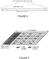
- FIGURE 2 illustrates the LTE time-domain structure.
- LTE downlink transmissions are organized into radio frames of 10 ms.
- subframe length is fixed at 1ms as in LTE.
- a subframe in NR is further divided into a number of slots each with 14 OFDM symbols.
- the slot length for a reference numerology of (15 ⁇ 2 ⁇ ) kHz is exactly 2 - ⁇ ms.
- the resource allocation in LTE is typically described in terms of resource blocks, where a resource block corresponds to one slot (0.5 ms) in the time domain and 12 contiguous subcarriers in the frequency domain. Resource blocks are numbered in the frequency domain, starting with 0 from one end of the system bandwidth. For NR, a resource block is also 12 subcarriers in frequency domain.
- Downlink transmissions are dynamically scheduled. For example, in each subframe or slot, the gNB may transmit control information about to which terminals data is transmitted and upon which resource blocks the data is transmitted, in the current downlink subframe or slot.
- This control signaling is typically transmitted in the first 1, 2, 3 or 4 OFDM symbols in each subframe in LTE and 1 or 2 OFDM symbols of a slot in NR.
- a downlink system with 3 OFDM symbols as control for LTE is illustrated in FIGURE 3 .
- Multi-antenna techniques can significantly increase the data rates and reliability of a wireless communication system. The performance is in particular improved if both the transmitter and the receiver are equipped with multiple antennas, which results in a multiple-input multiple-output (MIMO) communication channel.
- MIMO multiple-input multiple-output
- Such systems and/or related techniques are commonly referred to as MIMO.
- NR is currently evolving with MIMO support.
- a core component in NR is the support of MIMO antenna deployments and MIMO related techniques including beamforming at higher carrier frequencies.
- LTE and NR support an 8-layer spatial multiplexing mode for up to 32 transmit (Tx) antennas with channel dependent precoding.
- the spatial multiplexing mode is aimed for high data rates in favorable channel conditions.
- FIGURE 4 illustrates an example spatial multiplexing operation. More particularly, FIGURE 4 illustrates an example transmission structure of precoded spatial multiplexing mode in LTE and NR.
- the information carrying symbol vector s is multiplied by an N T ⁇ r precoder matrix W, which serves to distribute the transmit energy in a subspace of the N T (corresponding to N T antenna ports) dimensional vector space.
- the precoder matrix is typically selected from a codebook of possible precoder matrices, and typically indicated by means of a precoder matrix indicator (PMI), which specifies a unique precoder matrix in the codebook for a given number of symbol streams.
- the r symbols in s each correspond to a layer and r is referred to as the transmission rank. In this way, spatial multiplexing is achieved since multiple symbols can be transmitted simultaneously over the same time/frequency resource element (TFRE).
- the number of symbols r is typically adapted to suit the current channel properties.
- the precoder W can be a wideband precoder, which is constant over frequency, or frequency selective.
- the precoder matrix is often chosen to match the characteristics of the N R x N T MIMO channel matrix H n , resulting in so-called channel-dependent precoding. This is also commonly referred to as closed-loop precoding and essentially strives for focusing the transmit energy into a subspace which is strong in the sense of conveying much of the transmitted energy to the UE.
- the precoder matrix may also be selected to strive for orthogonalizing the channel, meaning that after proper linear equalization at the UE, the inter-layer interference is reduced.
- the transmission rank and thus the number of spatially multiplexed layers, is reflected in the number of columns of the precoder. For efficient performance, it is important that a transmission rank that matches the channel properties is selected.
- CSI-RS channel state information
- CRS common reference symbols
- CSI-RS provides several advantages over basing the channel state information (CSI) feedback on the common reference symbols (CRS) which were used, for that purpose, in previous releases of LTE. Firstly, the CSI-RS is not used for demodulation of the data signal, and thus does not require the same density as CRS (i.e., the overhead of the CSI-RS is substantially less). Secondly, CSI-RS provides a much more flexible means to configure CSI feedback measurements (e.g., which CSI-RS resource to measure on can be configured in a UE specific manner).
- a UE can estimate the effective channel the CSI-RS is traversing including the radio propagation channel and antenna gains.
- Up to 32 CSI-RS ports can be configured for a LTE or NR UE. That is, the UE can estimate the channel from up to thirty-two transmit antenna ports.
- An antenna port is equivalent to a reference signal resource that the UE shall use to measure the channel.
- a gNB with two antennas could define two CSI-RS ports, where each port is a set of resource elements in the time frequency grid within a subframe or slot.
- the base station transmits each of these two reference signals from each of the two antennas so that the UE can measure the two radio channels and report channel state information back to the base station based on these measurements.
- CSI-RS resources with 1, 2, 4, 8, 12, 16, 20, 24, 28 and 32 ports are supported.
- the CSI-RS utilizes an orthogonal cover code (OCC) of length two to overlay two antenna ports on two consecutive resource elements (REs).
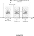
- FIGURES 5A-5C illustrate resource element grids. More particularly, FIGURES 5A-5C illustrate RE grids over a resource block (RB) pair showing potential positions for LTE Release 9/10 UE specific RS, CSI-RS (marked with a number corresponding to the CSI-RS antenna port), and CRS.
- the CSI-RS utilizes an orthogonal cover code (OCC) of length two to overlay two antenna ports on two consecutive REs.
- OCC orthogonal cover code
- many different CSI-RS patterns are available. For the case of 2 CSI-RS antenna ports, we see that there are 20 different patterns within a subframe. The corresponding number of patterns is 10 and 5 for 4 and 8 CSI-RS antenna ports, respectively. For TDD, some additional CSI-RS patterns are available.
- the CSI reference signal configurations are shown in TABLE 6.10.5.2-1 below, taken from TS 36.211 v12.5.0.
- PRB physical resource block
- NR In addition to multiple types of CSI-RS transmissions, NR also supports multiple types of CSI reporting. The following types of CSI reporting will be supported in NR
- LTE control signaling can be carried in a variety of ways, including carrying control information on a physical downlink control channel (PDCCH) or a physical uplink control channel (PUCCH), embedded in a physical uplink shared channel (PUSCH), in medium access control-control elements (MAC-CEs), or in RRC signaling.
- PDCCH physical downlink control channel
- PUCCH physical uplink control channel
- PUSCH physical uplink shared channel
- MAC-CEs medium access control-control elements
- RRC signaling RRC signaling.
- Control information carried on PDCCH, PUCCH, or embedded in PUSCH is physical layer related control information, such as downlink control information (DCI), uplink control information (UCI), as described in 3GPP TS 36.211, 36.212, and 36.213, or corresponding specifications in the 38 series.
- DCI is generally used to instruct the UE to perform some physical layer function, providing the needed information to perform the function.
- UCI generally provides the network with needed information, such as hybrid automatic repeat request-acknowledgment (HARQ-ACK), scheduling request (SR), channel state information (CSI), including channel quality indicator (CQI), pre-coding matrix indicator (PMI), rank indicator (RI), and/or contention resolution identity (CRI).
- HARQ-ACK hybrid automatic repeat request-acknowledgment
- SR scheduling request
- CSI channel state information
- CQI channel quality indicator
- PMI pre-coding matrix indicator
- RI rank indicator
- CRI contention resolution identity
- UCI and DCI can be transmitted on a subframe-by-subframe basis, and so are designed to support rapidly varying parameters, including those that can vary with a fast fading radio channel. Because UCI and DCI can be transmitted in every subframe, UCI or DCI corresponding to a given cell tend to be on the order of tens of bits, in order to limit the amount of control overhead.
- Control information carried in MAC CEs is carried in MAC headers on the uplink and downlink shared transport channels (UL-SCH and DL-SCH), as described in 3GPP TS 36.321. Since a MAC header does not have a fixed size, control information in MAC CEs can be sent when it is needed, and does not necessarily represent a fixed overhead. Furthermore, MAC CEs can carry larger control payloads efficiently, since they are carried in UL-SCH or DL-SCH transport channels, which benefit from link adaptation, HARQ, and can be turbo coded.
- MAC CEs are used to perform repetitive tasks that use a fixed set of parameters, such as maintaining timing advance or buffer status reporting, but these tasks generally do not require transmission of a MAC CE on a subframe-by-subframe or slot-by-slot basis. Consequently, channel state information related to a fast fading radio channel, such as PMI, CQI, RI, and CRI are not carried in MAC CEs in LTE up to Rel-14.
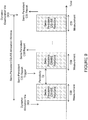
- FIGURE 7 illustrates an example of MAC CE based dynamic allocation signaling for beginning semi-persistent CSI-RS transmission.
- this MAC CE based solution generally there is a delay, denoted as X, between the dynamic allocation signaling and the beginning of semi-persistent CSI-RS measurement. This delay includes the following:
- FIGURE 8 illustrates an example of MAC CE based dynamic deallocation signaling for stopping semi-persistent CSI-RS transmission.
- the delay between the dynamic deallocation signal and the ending of the semi-persistent CSI-RS measurement is denoted as Y.
- Y the delay between the dynamic deallocation signal and the ending of the semi-persistent CSI-RS measurement. Due to reasons stated above, a major problem with the MAC CE based dynamic deallocation to stop semi-persistent CSI-RS transmission is that it involves long deallocation delays. The gNB does not have much control over the time gap between dynamic deallocation and the stopping of semi-persistent CSI-RS measurement as this time gap Y is determined by MAC CE decoding delay and HARQ ACK/NACK feedback delay, etc.
- FIGURE 9 illustrates the problems for the combination of semi-persistent CSI-RS measurement with semi-persistent CSI reporting, the above problems are also present when semi-persistent CSI-RS is combined with aperiodic (single-shot) CSI reporting
- DCI based dynamic indication for semi-persistent CSI-RS measurement provides better control of the time gaps X and Y abovementioned.
- the gNB since there is no HARQ acknowledgement associated with the reception of the DCI, the gNB does not know whether or not the UE has successfully received the DCI indication.
- reliability is a problem associated with DCI based dynamic indication to start/stop semi-persistent CSI-RS measurements.
- FIGURES 7-9 illustrate the problems for the combination of semi-persistent CSI-RS measurement with semi-persistent CSI reporting, the above problems are also present when semi-persistent CSI-RS is combined with aperiodic (single-shot) CSI reporting.
- a method in a wireless device includes receiving, from a network node, dynamic allocation signaling to commence measurement on a semi-persistent CSI-RS resource.
- a first measurement is performed on the CSI-RS resource.
- a first CSI report based only on the first measurement is transmitted to the network node.
- a trigger message is received from the network node that is different from the dynamic allocation signaling. The trigger message triggers semi-persistent CSI reporting, and the wireless device performs semi-persistent reporting.
- a wireless device includes a memory storing instructions and processing circuitry operable to execute the instructions to cause the wireless device to receive, from a network node, dynamic allocation signaling to commence measurement of a semi-persistent CSI-RS resource.
- a first measurement of the CSI-RS resource is performed, and a first CSI report based only on the first measurement is transmitted to the network node.
- a trigger message is received from the network node that is different from the dynamic allocation signaling. The trigger message triggers semi-persistent CSI reporting, and the wireless device performs semi-persistent reporting.
- a method in a network node includes transmitting, to a wireless device, dynamic allocation signaling to initiate measurement of a semi-persistent CSI-RS resource. It is determined whether a first CSI report is transmitted by the wireless device in response to the dynamic allocation signaling and an action is taken based on whether the first CSI report is received in response to the dynamic allocation trigger.
- a network node includes a memory storing instructions and processing circuitry operable to execute the instructions to cause the network node to transmit, to a wireless device, dynamic allocation signaling to initiate measurement of a semi-persistent CSI-RS resource. It is determined whether a first CSI report is transmitted by the wireless device in response to the dynamic allocation signaling and an action is taken based on whether the first CSI report is received in response to the dynamic allocation trigger.
- Certain embodiments of the present disclosure may provide one or more technical advantages. For example, certain embodiments may avoid the long allocation/deallocation latencies associated with schemes such as MAC CE based allocation/deallocation. According to certain embodiments, a technical advantage may be that the semi-persistent CSI-RS measurement can occur in the same subframe or slot as the activation/allocation trigger. Still another technical advantage may be the high reliability of the DCI based allocation or deallocation to start or stop semi-persistent CSI-RS measurements (and thus gNB transmissions of CSI-RS), which has similar reliability as MAC CE based approaches.
- Particular embodiments of the present disclosure may provide solutions reliable dynamic indication for semi-persistent channel state information reference signal (CSI-RS).
- certain embodiments may provide reliable downlink control information (DCI) based dynamic allocation/deallocation for semi-persistent CSI-RS measurements.
- DCI downlink control information
- semi-persistent CSI-RS measurements in the wireless device is initiated with dynamic DCI based allocation signaling.
- the wireless device measures the first instance of the semi-persistent CSI-RS and the wireless device sends a first aperiodic channel state information (CSI) report based on the first measurement to the gNB.
- CSI channel state information
- a wireless device configured to have Aperiodic CSI reporting would begin measurements in response to successfully receiving a semi-persistent allocation but not transmit the CSI report until it receives an Aperiodic CSI trigger.
- the first aperiodic CSI report is triggered by the semi-persistent CSI-RS allocation trigger.
- the gNB can use this first aperiodic CSI report to verify that the UE received the dynamic allocation DCI indication successfully.
- a separate aperiodic CSI measurement report trigger may be sent from gNB to the wireless device after the semi-persistent CSI-RS measurement trigger so that the gNB can use the CSI report to verify the successful reception of the semi-persistent CSI-RS trigger by the wireless device.
- semi-persistent CSI reporting may be triggered in the wireless device by the gNB simultaneously with the same DCI as the semi-persistent CSI-RS measurement, then the gNB can use the semi-persistent CSI reports to verify whether the UE has received the trigger correctly.
- a mechanism is used where after receiving the DCI based dynamic deallocation of semi-persistent CSI-RS from the gNB, the wireless device stops measuring semi-persistent CSI-RS. If the wireless device received the DCI based dynamic deallocation indication successfully, the wireless device may not send further semi-persistent CSI reports after DCI based dynamic deallocation indication (i.e., since semi-persistent CSI-RS measurements have been stopped by the DCI based dynamic deallocation indication). Thus, not receiving further semi-persistent CSI reports can be used by the gNB to verify that the wireless device received the dynamic deallocation DCI indication successfully.
- receiving further semi-persistent CSI reports after DCI based dynamic deallocation indication is a negative acknowledgement that the dynamic deallocation DCI indication was received successfully.
- the gNB may then react by initiating a retransmission of the deallocation indication.
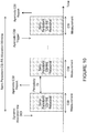
- FIGURE 10 illustrates example reliable DCI based dynamic allocation for semi-persistent CSI-RS with aperiodic CSI reporting, according to certain embodiments.
- a mechanism is used to ensure reliability of DCI based dynamic allocation to start measurement in the wireless device on semi-persistent CSI-RS, and possibly also to start CSI-RS transmissions from gNB. Note that triggering a measurement in the wireless device does not necessarily imply that a CSI-RS transmission is initiated, the CSI-RS may be present in earlier slots as well, used for measurements by other served wireless device.
- gNB when describing triggering of a measurement in the wireless device, it could mean that gNB starts transmitting the corresponding CSI-RS or it could mean that gNB simply continues to transmit that CSI-RS if that CSI-RS has been initiated earlier.
- gNB sends a DCI (possibly over physical downlink control channel (PDCCH)) with an indication of starting a semi-persistent CSI-RS measurement.
- the indication may be included in an uplink data grant.
- the first CSI-RS measurement (and thus a CSI-RS transmission) may occur in the same subframe or slot as the PDCCH.
- the wireless device After receiving the DCI based dynamic allocation of semi-persistent CSI-RS from the gNB, the wireless device measures the first instance of the semi-persistent CSI-RS transmission and sends a first aperiodic CSI report based on the first measurement to the gNB over the uplink resources allocated in the uplink data grant.
- the gNB may use this first aperiodic CSI report to verify that the wireless device received the dynamic allocation DCI indication successfully. If the gNB does not receive the aperiodic CSI report nor has a CSI decoding error after sending the dynamic allocation via DCI, then the gNB assumes that the wireless device has not received the dynamic DCI allocation successfully and retransmits the dynamic DCI allocation to the wireless device.
- the gNB transmission and wireless device measurements of semi-persistent CSI-RS continues with preconfigured periodicity as shown in FIGURE 10 .
- the DCI based dynamic allocation signal is triggered by the DCI based dynamic allocation signal, and separate aperiodic CSI triggers will trigger subsequent aperiodic CSI reports. That is, the DCI based dynamic allocation signals both the start of the semi-persistent CSI-RS measurement and also a request for the first aperiodic CSI report.
- the semi-persistent CSI-RS measurement (and possible initiation of the transmission from gNB if the CSI-RS not already being transmitted) is combined with semi-persistent CSI reporting.
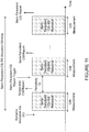
- FIGURE 11 illustrates reliable DCI based dynamic allocation where semi-persistent CSI-RS measurement and the semi-persistent CSI report are triggered by different DCI indications.
- a single-shot CSI report that follows immediately after the first instance of the semi-persistent CSI-RS measurement can be used by the gNB to verify that the wireless device received the dynamic allocation DCI successfully.
- This single-shot CSI report captures the wireless device's measurement of the first instance of the semi-persistent CSI-RS transmission. If the gNB does not receive the single-shot CSI report after sending the dynamic allocation via DCI, then the gNB assumes that the wireless device has not received the dynamic DCI allocation successfully and retransmits the dynamic DCI allocation to the wireless device. As shown in FIGURE 11 , only the single-shot CSI report is triggered by the DCI based dynamic allocation signal, and a separate semi-persistent CSI trigger initiates the semi-persistent CSI reports. That is, the DCI based dynamic allocation signal both starts the semi-persistent CSI-RS measurements (and possibly initiate the gNB transmission of CSI-RS) and also triggers the single-shot CSI report.
- semi-persistent CSI-RS measurement and semi-persistent CSI reporting may be triggered or activated using a single DCI.
- semi-persistent CSI-RS measurement is triggered by the DCI in the same way as in embodiments 2 and 3.
- semi-persistent CSI reporting is also activated by the same DCI. For example, when a wireless device receives the DCI, it assumes that a semi-persistent CSI-RS transmission starts in the same subframe or slot as the one over which the DCI is received and the UE starts measuring CSI based on the configured CSI-RS and reports CSI periodically according the configured reporting periodicity and subframe or slot offsets.
- the gNB receives CSI at the configured subframes or slots successfully from the wireless device, then the semi-persistent CSI-RS measurement is initiated successfully, otherwise if the gNB did not detect the expected CSI reports successfully, then the initiation is not successful and another DCI would be sent to the UE to initiate semi-persistent CSI-RS measurements.
- FIGURE 12 illustrates reliable DCI based dynamic deallocation for semi-persistent CSI-RS with semi-persistent CSI reporting.
- the wireless device after receiving the DCI based dynamic deallocation of semi-persistent CSI-RS from the gNB, the wireless device assumes that the semi-persistent CSI-RS transmission has been stopped after the subframe or slot over which the DCI is received and, thus, stops measuring semi-persistent CSI-RS.
- the wireless device will not send further semi-persistent CSI reports after DCI based dynamic deallocation indication (i.e., since semi-persistent CSI-RS transmissions have been stopped by the DCI based dynamic deallocation indication). As such, not receiving further semi-persistent CSI reports can be used by the gNB to verify that the wireless device received the dynamic deallocation DCI indication successfully.
- receiving further semi-persistent CSI reports after DCI based dynamic deallocation indication is a negative acknowledgement that the dynamic deallocation DCI indication was received successfully.
- the gNB If the gNB does receive further semi-persistent CSI reports after sending the dynamic deallocation via DCI, then the gNB assumes that the wireless device has not received the dynamic DCI deallocation successfully and retransmits the dynamic DCI deallocation to the wireless device. Both "not receiving further semi-persistent CSI reports" and “receive further semi-persistent CSI reports” can be indicated by whether CSI reports are decoded correctly or incorrectly. Multiple report instances may be monitored to ensure detection reliability.
- FIGURE 13 is a block diagram illustrating an embodiment of a wireless network 100 for reliable dynamic indication for semi-persistent CSI-RS, in accordance with certain embodiments.
- Network 100 includes one or more wireless devices 110A-C, which may be interchangeably referred to as wireless devices 110 or UEs 110, and network nodes 115A-C, which may be interchangeably referred to as network nodes 115 or eNodeBs 115.
- a wireless device 110 may communicate with network nodes 115 over a wireless interface.
- wireless device 110A may transmit wireless signals to one or more of network nodes 115, and/or receive wireless signals from one or more of network nodes 115.
- the wireless signals may contain voice traffic, data traffic, control signals, and/or any other suitable information.
- wireless devices 110 may have device to device (D2D) capability. Thus, wireless devices 110 may be able to receive signals from and/or transmit signals directly to another wireless device 110. For example, wireless device 110A may be able to receive signals from and/or transmit signals to wireless device 110B.
- D2D device to device
- network nodes 115 may interface with a radio network controller (not depicted in FIGURE 13 ).
- the radio network controller may control network nodes 115 and may provide certain radio resource management functions, mobility management functions, and/or other suitable functions.
- the functions of the radio network controller may be included in network node 115.
- the radio network controller may interface with a core network node.
- the radio network controller may interface with the core network node via an interconnecting network.
- the interconnecting network may refer to any interconnecting system capable of transmitting audio, video, signals, data, messages, or any combination of the preceding.
- the interconnecting network may include all or a portion of a public switched telephone network (PSTN), a public or private data network, a local area network (LAN), a metropolitan area network (MAN), a wide area network (WAN), a local, regional, or global communication or computer network such as the Internet, a wireline or wireless network, an enterprise intranet, or any other suitable communication link, including combinations thereof.
- PSTN public switched telephone network
- LAN local area network
- MAN metropolitan area network
- WAN wide area network
- Internet a local, regional, or global communication or computer network
- wireline or wireless network such as the Internet
- enterprise intranet an enterprise intranet, or any other suitable communication link, including combinations thereof.
- the core network node may manage the establishment of communication sessions and various other functionalities for wireless devices 110.
- Wireless devices 110 may exchange certain signals with the core network node using the non-access stratum layer.
- signals between wireless devices 110 and the core network node may be transparently passed through the radio access network.
- network nodes 115 may interface with one or more network nodes over an internode interface. For example, network nodes 115A and 115B may interface over an X2 interface.
- example embodiments of network 100 may include one or more wireless devices 110, and one or more different types of network nodes capable of communicating (directly or indirectly) with wireless devices 110.
- Wireless device 110 may refer to any type of wireless device communicating with a node and/or with another wireless device in a cellular or mobile communication system. Examples of wireless device 110 include a mobile phone, a smart phone, a PDA (Personal Digital Assistant), a portable computer (e.g., laptop, tablet), a sensor, a modem, a machine-type-communication (MTC) device / machine-to-machine (M2M) device, laptop embedded equipment (LEE), laptop mounted equipment (LME), USB dongles, a D2D capable device, or another device that can provide wireless communication.
- MTC machine-type-communication
- M2M machine-to-machine
- LME laptop mounted equipment
- USB dongles a D2D capable device, or another device that can provide wireless communication.
- a wireless device 110 may also be referred to as UE, a station (STA), a device, or a terminal in some embodiments.
- radio network node (or simply “network node”) is used. It can be any kind of network node, which may comprise a Node B, base station (BS), multi-standard radio (MSR) radio node such as MSR BS, eNode B, network controller, radio network controller (RNC), base station controller (BSC), relay donor node controlling relay, base transceiver station (BTS), access point (AP), transmission points, transmission nodes, RRU, RRH, nodes in distributed antenna system (DAS), core network node (e.g.
- Example embodiments of wireless devices 110, network nodes 115, and other network nodes are described in more detail with respect to FIGURES 14 , 18 , and 21 , respectively.
- FIGURE 13 illustrates a particular arrangement of network 100
- network 100 may include any suitable number of wireless devices 110 and network nodes 115, as well as any additional elements suitable to support communication between wireless devices or between a wireless device and another communication device (such as a landline telephone).
- network 100 may include any suitable number of wireless devices 110 and network nodes 115, as well as any additional elements suitable to support communication between wireless devices or between a wireless device and another communication device (such as a landline telephone).
- RAT radio access technology
- multi-RAT multi-RAT systems in which the wireless device receives and/or transmits signals (e.g., data).
- the various embodiments described herein may be applicable to LTE, LTE-Advanced, LTE-U Universal Mobile Telecommunications System (UMTS), High Speed Packet Access (HSPA), Global System for Mobile Communications (GSM), cdma2000, WiMax, WiFi, another suitable radio access technology, or any suitable combination of one or more radio access technologies.
- UMTS Universal Mobile Telecommunications System
- HSPA High Speed Packet Access
- GSM Global System for Mobile Communications
- cdma2000 Wireless Fidelity
- WiMax Wireless Fidelity
- WiFi Wireless Fidelity
- LAA Licensed Assisted Access
- standalone LTE operation in license-exempt channels.
- the described techniques are generally applicable for transmissions from both network nodes 115 and wireless devices 110.
- FIGURE 14 illustrates an example wireless device 110 reliable dynamic indication for semi-persistent CSI-RS, in accordance with certain embodiments.
- wireless device 210 includes transceiver 210, processing circuitry 220, and memory 230.
- transceiver 210 facilitates transmitting wireless signals to and receiving wireless signals from network node 115 (e.g., via an antenna 240), processing circuitry 220 executes instructions to provide some or all of the functionality described above as being provided by wireless device 110, and memory 230 stores the instructions executed by processing circuitry 220. Examples of a wireless device 110 are provided above.
- Processing circuitry 220 may include any suitable combination of hardware and software implemented in one or more modules to execute instructions and manipulate data to perform some or all of the described functions of wireless device 110.
- processing circuitry 220 may include, for example, one or more computers, one or more central processing units (CPUs), one or more processors, one or more microprocessors, one or more applications, and/or other logic.
- Memory 230 is generally operable to store instructions, such as a computer program, software, an application including one or more of logic, rules, algorithms, code, tables, etc. and/or other instructions capable of being executed by processing circuitry.
- Examples of memory 230 include computer memory (for example, Random Access Memory (RAM) or Read Only Memory (ROM)), mass storage media (for example, a hard disk), removable storage media (for example, a Compact Disk (CD) or a Digital Video Disk (DVD)), and/or or any other volatile or non-volatile, non-transitory computer-readable and/or computer-executable memory devices that store information.
- RAM Random Access Memory
- ROM Read Only Memory
- mass storage media for example, a hard disk
- removable storage media for example, a Compact Disk (CD) or a Digital Video Disk (DVD)
- CD Compact Disk
- DVD Digital Video Disk
- wireless device 110 may include additional components beyond those shown in FIGURE 14 that may be responsible for providing certain aspects of the wireless device's functionality, including any of the functionality described above and/or any additional functionality (including any functionality necessary to support the solution described above).
- FIGURE 15 illustrates an example method by a wireless device 110 for initiating semi-persistent CSI measurements on a CSI-RS resource configured by higher layers, according to certain embodiments.
- the method begins at step 304 when wireless device 110 receives, from network node 115, a dynamic allocation trigger to commence measurement of a semi-persistent CSI-RS resource.
- a first measurement of the CSI-RS resource is performed.
- a first CSI report based only on the first measurement is transmitted to the network node 115.
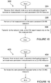
- FIGURE 16 illustrates an example method a wireless device 110 for terminating semi-persistent CSI measurements on a CSI-RS resource configured by higher layers, according to certain embodiments.
- the method begins at step 404 when wireless device 110 receives, from a network node, a dynamic deallocation trigger to terminate semi-persistent measurements on a CSI-RS resource.
- wireless device 110 terminates the semi-persistent measurements on the CSI-RS resource.
- FIGURE 17 illustrates an example method by a wireless device 110, according to certain embodiments.
- the method begins at step 502 when wireless device 110 receives, from a network node 115, dynamic allocation signaling to commence measurement on a semi-persistent CSI-RS resource.
- the semi-persistent CSI-RS resource includes a CSI-RS resource that is configured with at least a CSI-RS transmission periodicity and for which at least one UE assumption on transmission and cessation of CSI-RS transmission applies.
- the semi-persistent CSI-RS resource may be configured for transmission of CSI-RS at a configured periodicity for a limited time duration and receipt of the dynamic allocation may be required to trigger to transmission of the semi-persistent CSI-RS on the semi-persistent CSI-RS resource.
- the dynamic allocation signaling initiates semi-persistent CSI measurements on the CSI-RS resource and also trigger the first CSI report.
- the dynamic allocation signaling includes at least one of an indication of semi-persistent CSI-RS measurement initiation, an indication of semi-persistent CSI-RS resource configuration index/indices, and an uplink resource allocation and associated modulation and coding rate.
- the dynamic allocation signaling comprises a MAC CE.
- wireless device 110 performs a first measurement on the semi-persistent CSI-RS resource.
- Wireless device 110 transmits, to the network node 115, a first CSI report based only on the first measurement at step 506.
- the first CSI report is an aperiodic report.
- the first CSI report is a semi-persistent report.
- wireless device 110 receives, from the network node 115, a trigger message that is different than the dynamic allocation signaling of step 502.
- the trigger message triggers semi-persistent CSI reporting.
- the trigger message includes DCI.
- wireless device 110 initiates semi-persistent reporting in response to the trigger message.
- wireless device 110 may transmit a plurality of semi-persistent CSI reports.
- wireless device 110 may cease transmission of the semi-persistent CSI-RS reports after a predetermined length of time.
- wireless device 110 may receive dynamic deallocation signaling to terminate the measurement of on the semi-persistent CSI-RS resource and cease the semi-persistent measurements on the semi-persistent CSI-RS resource in response to the dynamic deallocation trigger.
- FIGURE 18 illustrate an example network node 115 for reliable dynamic indication for semi-persistent CSI-RS, according to certain embodiments.
- network node 115 may be any type of radio network node or any network node that communicates with a wireless device and/or with another network node. Examples of a network node 115 are provided above.
- Network nodes 115 may be deployed throughout network 100 as a homogenous deployment, heterogeneous deployment, or mixed deployment.
- a homogeneous deployment may generally describe a deployment made up of the same (or similar) type of network nodes 115 and/or similar coverage and cell sizes and inter-site distances.
- a heterogeneous deployment may generally describe deployments using a variety of types of network nodes 115 having different cell sizes, transmit powers, capacities, and inter-site distances.
- a heterogeneous deployment may include a plurality of low-power nodes placed throughout a macro-cell layout.
- Mixed deployments may include a mix of homogenous portions and heterogeneous portions.
- Network node 115 may include one or more of transceiver 610, processing circuitry 620, memory 630, and network interface 640.
- transceiver 610 facilitates transmitting wireless signals to and receiving wireless signals from wireless device 110 (e.g., via an antenna 650)
- processing circuitry 620 executes instructions to provide some or all of the functionality described above as being provided by a network node 115
- memory 630 stores the instructions executed by processing circuitry 620
- network interface 640 communicates signals to backend network components, such as a gateway, switch, router, Internet, Public Switched Telephone Network (PSTN), core network nodes or radio network controllers, etc.
- PSTN Public Switched Telephone Network
- network node 115 may be capable of using multi-antenna techniques, and may be equipped with multiple antennas and capable of supporting MIMO techniques.
- the one or more antennas may have controllable polarization.
- each element may have two co-located sub elements with different polarizations (e.g., 90 degree separation as in cross-polarization), so that different sets of beamforming weights will give the emitted wave different polarization.
- Processing circuitry 620 may include any suitable combination of hardware and software implemented in one or more modules to execute instructions and manipulate data to perform some or all of the described functions of network node 115.
- processing circuitry 620 may include, for example, one or more computers, one or more central processing units (CPUs), one or more microprocessors, one or more applications, and/or other logic.
- Memory 630 is generally operable to store instructions, such as a computer program, software, an application including one or more of logic, rules, algorithms, code, tables, etc. and/or other instructions capable of being executed by a processor.
- Examples of memory 630 include computer memory (for example, Random Access Memory (RAM) or Read Only Memory (ROM)), mass storage media (for example, a hard disk), removable storage media (for example, a Compact Disk (CD) or a Digital Video Disk (DVD)), and/or or any other volatile or non-volatile, non-transitory computer-readable and/or computer-executable memory devices that store information.
- RAM Random Access Memory
- ROM Read Only Memory
- mass storage media for example, a hard disk
- removable storage media for example, a Compact Disk (CD) or a Digital Video Disk (DVD)
- CD Compact Disk
- DVD Digital Video Disk
- network interface 640 is communicatively coupled to processing circuitry 620 and may refer to any suitable device operable to receive input for network node 115, send output from network node 115, perform suitable processing of the input or output or both, communicate to other devices, or any combination of the preceding.
- Network interface 640 may include appropriate hardware (e.g., port, modem, network interface card, etc.) and software, including protocol conversion and data processing capabilities, to communicate through a network.
- network node 115 may include additional components beyond those shown in FIGURE 18 that may be responsible for providing certain aspects of the radio network node's functionality, including any of the functionality described above and/or any additional functionality (including any functionality necessary to support the solutions described above).
- the various different types of network nodes may include components having the same physical hardware but configured (e.g., via programming) to support different radio access technologies, or may represent partly or entirely different physical components. Additionally, the terms first and second are provided for example purposes only and may be interchanged.
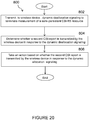
- FIGURE 19 illustrates an example method for initiating semi-persistent CSI measurements on a CSI-RS resource configured by higher layers, according to certain embodiments.
- the method begins at step 702 when network node 115 transmits, to the wireless device 110, dynamic allocation signaling to initiate measurement on a semi-persistent CSI-RS resource.
- the semi-persistent CSI-RS resource includes a CSI-RS resource that is configured with at least a CSI-RS transmission periodicity and for which at least one UE assumption on transmission and cessation of CSI-RS transmission applies.
- the semi-persistent CSI-RS resource may be configured for transmission of CSI-RS at a configured periodicity for a limited time duration and receipt of the dynamic allocation may be required to trigger to transmission of the semi-persistent CSI-RS on the semi-persistent CSI-RS resource.
- the dynamic allocation signaling includes at least one of an indication of semi-persistent CSI-RS measurement initiation, an indication of semi-persistent CSI-RS resource configuration index/indices, and an uplink resource allocation and associated modulation and coding rate.
- the dynamic allocation signaling comprises a MAC CE.
- step 704 it is determined whether a first CSI report is transmitted by wireless device 110 in response to the dynamic allocation signaling.
- network node 115 takes an action based on whether the first CSI report is transmitted by wireless device 110 in response to the dynamic allocation signaling.
- determining whether a first CSI report is transmitted by wireless device 110 may include determining that the first CSI report was received by network node 115.
- the first CSI report may indicate to network node 115 that wireless device 110 successfully received the dynamic allocation signaling.
- network node may continue transmission of semi-persistent CSI-RS with preconfigured periodicity.
- determining whether a first CSI report is transmitted by wireless device 110 may include determining that the first CSI report was not received by network node 115. Not receiving the first CSI report may indicate to network node 115 that wireless device 110 did not successfully receive the dynamic allocation signaling. Thus, network node 115 may retransmit the dynamic allocation signaling to wireless device 110.
- wireless device 110 may cease transmission of the semi-persistent CSI-RS reports after a predetermined length of time.
- network node 115 may transmit dynamic deallocation signaling to terminate the measurement of on the semi-persistent CSI-RS resource by the wireless device 110.
- network node 115 may determine whether a second CSI report is transmitted by the wireless device in response to the dynamic deallocation signaling and take an action based on whether the second CSI report is transmitted by the wireless device in response to the dynamic allocation signaling.
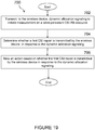
- FIGURE 20 illustrates an example method by network node 115 for terminating semi-persistent CSI measurements on a CSI-RS resource configured by higher layers, according to certain embodiments.
- the method begins at step 802 when network node 115 transmits to wireless device 110 dynamic deallocation signaling to terminate measurement on a semi-persistent CSI-RS resource.
- the dynamic deallocation signaling may include DCI.
- network node 115 determines whether a second CSI report is transmitted by wireless device 110 in response to the dynamic deallocation signaling.
- network node 115 takes an action based on whether the second CSI report is received in response to the dynamic deallocation signaling.
- the second CSI report may be determined that the second CSI report was received. Receipt of the second CSI report may indicate to network node 115 that wireless device 110 did not receive the dynamic deallocation signaling. Thus, network node 115 may take further action to retransmit the dynamic deallocation signaling.
- FIGURE 21 illustrates an exemplary radio network controller or core network node 900, in accordance with certain embodiments.
- network nodes can include a mobile switching center (MSC), a serving GPRS support node (SGSN), a mobility management entity (MME), a radio network controller (RNC), a base station controller (BSC), and so on.
- the radio network controller or core network node 900 include processor or processing circuitry 920, memory 930, and network interface 940.
- processor 920 executes instructions to provide some or all of the functionality described above as being provided by the network node
- memory 930 stores the instructions executed by processor 920
- network interface 940 communicates signals to any suitable node, such as a gateway, switch, router, Internet, Public Switched Telephone Network (PSTN), network nodes 115, radio network controllers or core network nodes 900, etc.
- PSTN Public Switched Telephone Network
- Processor 920 may include any suitable combination of hardware and software implemented in one or more modules to execute instructions and manipulate data to perform some or all of the described functions of the radio network controller or core network node 900.
- processor 920 may include, for example, one or more computers, one or more central processing units (CPUs), one or more microprocessors, one or more applications, and/or other logic.
- Memory 930 is generally operable to store instructions, such as a computer program, software, an application including one or more of logic, rules, algorithms, code, tables, etc. and/or other instructions capable of being executed by a processor.
- Examples of memory 930 include computer memory (for example, Random Access Memory (RAM) or Read Only Memory (ROM)), mass storage media (for example, a hard disk), removable storage media (for example, a Compact Disk (CD) or a Digital Video Disk (DVD)), and/or or any other volatile or non-volatile, non-transitory computer-readable and/or computer-executable memory devices that store information.
- RAM Random Access Memory
- ROM Read Only Memory
- mass storage media for example, a hard disk
- removable storage media for example, a Compact Disk (CD) or a Digital Video Disk (DVD)
- CD Compact Disk
- DVD Digital Video Disk
- network interface 940 is communicatively coupled to processor 920 and may refer to any suitable device operable to receive input for the network node, send output from the network node, perform suitable processing of the input or output or both, communicate to other devices, or any combination of the preceding.
- Network interface 940 may include appropriate hardware (e.g., port, modem, network interface card, etc.) and software, including protocol conversion and data processing capabilities, to communicate through a network.
- network node may include additional components beyond those shown in FIGURE 21 that may be responsible for providing certain aspects of the network node's functionality, including any of the functionality described above and/or any additional functionality (including any functionality necessary to support the solution described above).
- a method in a wireless device may be provided for initiating semi-persistent CSI measurements on a CSI-RS resource configured by higher layers, wherein the resource is used for CSI reporting, for which resource the wireless device is not currently performing measurements.
- the method may include:
- a wireless device for initiating semi-persistent CSI measurements on a CSI-RS resource configured by higher layers, wherein the resource is used for CSI reporting, for which resource the wireless device is not currently performing measurements.
- the wireless device may include:
- method in a wireless device for terminating semi-persistent CSI measurements on a CSI-RS resource configured by higher layers wherein the resource is used for CSI reporting, for which resource the wireless device is currently performing measurements.
- the method may include
- the method may include
- a network node for initiating semi-persistent CSI measurements on a CSI-RS resource by a wireless device configured by higher layers, wherein the resource is used for CSI reporting, for which resource the wireless device is not currently performing measurements.
- the network node may include:
- the method may include:
- a network node for terminating semi-persistent CSI measurements on a CSI-RS resource by a wireless device configured by higher layers, wherein the resource is used for CSI reporting, for which resource the wireless device is currently performing measurements.
Description
- The present disclosure relates, in general, to wireless communications and, more particularly, systems and methods for reliable dynamic indication for semi-persistent channel state information-reference signal (CSI-RS).
- The fifth generation of mobile telecommunications and wireless technology is not yet fully defined but in an advanced draft stage within 3GPP. It includes work on 5G New Radio (NR) Access Technology. Long-Term Evolution (LTE) terminology is used in this disclosure in a forward looking sense, to include equivalent 5G entities or functionalities although a different term is specified in 5G. A general description of the agreements on 5G New Radio (NR) Access Technology so far is contained in 3GPP TR 38.802 VI.0.0 (2016-11). Final specifications may be published inter alia in the future 3GPP TS 38.2** series.
- The next generation mobile wireless communication system (5G or NR) may support a diverse set of use cases and a diverse set of deployment scenarios. The latter may include deployment at both low frequencies (100s of MHz), similar to LTE today, and very high frequencies (mm waves in the tens of GHz). At high frequencies, propagation characteristics make achieving good coverage challenging. One solution to the coverage issue may include employing high-gain beamforming, typically facilitated by analog circuitry, in order to achieve satisfactory link budget. Beamforming will also be used at lower frequencies (typically digital beamforming using mainly digital circuitry), and is expected to be similar in nature to the already standardized 3GPP LTE system (4G).
- Some of the key aspects of LTE are described herein. Of particular relevance is discussion of channel state information-reference signal (CSI-RS). A similar signal is expected to be designed also for NR and is the subject of the disclosure below.
- Note that terminology used here such as gNodeB (gNB) and user equipment (UE) should be considered non-limiting and does in particular not imply a certain hierarchical relation between the two; in general "gNB" could be read as a reference to
generic device 1 and "UE" asdevice 2, wherein these two generic devices communicate with each other over some radio channel. Alternatively, other terminology such as "gNodeB" can be used in place of "gNB" in different communication systems. Herein, the focus is on wireless transmissions in the downlink, but the techniques are equally applicable in the uplink. - LTE and NR use orthogonal frequency division multiplexing (OFDM) in the downlink and discrete Fourier transform spread (DFT-spread) OFDM or OFDM in the uplink.
FIGURE 1 illustrates the basic LTE downlink physical resource. LTE uses OFDM in the downlink and DFT-spread OFDM in the uplink. The basic LTE downlink physical resource can thus be seen as a time-frequency grid, where each resource element (or time/frequency resource element (TFRE)) corresponds to one OFDM subcarrier during one OFDM symbol interval. Although a subcarrier spacing of Δf = 15 kHz is shown inFIGURE 1 , different subcarrier spacing values are supported in NR The supported subcarrier spacing values (also reference to as different numerologies) in NR are given by Δf = (15× 2α) kHz where α is a non-negative integer. -
FIGURE 2 illustrates the LTE time-domain structure. In the time domain, LTE downlink transmissions are organized into radio frames of 10 ms. Each radio frame consists of ten equally-sized subframes of length Tsubframe = 1 ms. In NR, subframe length is fixed at 1ms as in LTE. A subframe in NR is further divided into a number of slots each with 14 OFDM symbols. The slot length for a reference numerology of (15× 2α) kHz is exactly 2-α ms. - The resource allocation in LTE is typically described in terms of resource blocks, where a resource block corresponds to one slot (0.5 ms) in the time domain and 12 contiguous subcarriers in the frequency domain. Resource blocks are numbered in the frequency domain, starting with 0 from one end of the system bandwidth. For NR, a resource block is also 12 subcarriers in frequency domain.
- Downlink transmissions are dynamically scheduled. For example, in each subframe or slot, the gNB may transmit control information about to which terminals data is transmitted and upon which resource blocks the data is transmitted, in the current downlink subframe or slot. This control signaling is typically transmitted in the first 1, 2, 3 or 4 OFDM symbols in each subframe in LTE and 1 or 2 OFDM symbols of a slot in NR. A downlink system with 3 OFDM symbols as control for LTE is illustrated in
FIGURE 3 . - Multi-antenna techniques can significantly increase the data rates and reliability of a wireless communication system. The performance is in particular improved if both the transmitter and the receiver are equipped with multiple antennas, which results in a multiple-input multiple-output (MIMO) communication channel. Such systems and/or related techniques are commonly referred to as MIMO.
- NR is currently evolving with MIMO support. A core component in NR is the support of MIMO antenna deployments and MIMO related techniques including beamforming at higher carrier frequencies. Currently LTE and NR support an 8-layer spatial multiplexing mode for up to 32 transmit (Tx) antennas with channel dependent precoding. The spatial multiplexing mode is aimed for high data rates in favorable channel conditions.
-
FIGURE 4 illustrates an example spatial multiplexing operation. More particularly,FIGURE 4 illustrates an example transmission structure of precoded spatial multiplexing mode in LTE and NR. As depicted, the information carrying symbol vector s is multiplied by an N T × r precoder matrix W, which serves to distribute the transmit energy in a subspace of the N T (corresponding to N T antenna ports) dimensional vector space. The precoder matrix is typically selected from a codebook of possible precoder matrices, and typically indicated by means of a precoder matrix indicator (PMI), which specifies a unique precoder matrix in the codebook for a given number of symbol streams. The r symbols in s each correspond to a layer and r is referred to as the transmission rank. In this way, spatial multiplexing is achieved since multiple symbols can be transmitted simultaneously over the same time/frequency resource element (TFRE). The number of symbols r is typically adapted to suit the current channel properties. - LTE and NR use OFDM in the downlink and hence the received N R x 1 vector yn for a certain TFRE on subcarrier n (or alternatively data TFRE number n) is thus modeled by

- The precoder matrix is often chosen to match the characteristics of the NR x N T MIMO channel matrix H n, resulting in so-called channel-dependent precoding. This is also commonly referred to as closed-loop precoding and essentially strives for focusing the transmit energy into a subspace which is strong in the sense of conveying much of the transmitted energy to the UE. In addition, the precoder matrix may also be selected to strive for orthogonalizing the channel, meaning that after proper linear equalization at the UE, the inter-layer interference is reduced.
- The transmission rank, and thus the number of spatially multiplexed layers, is reflected in the number of columns of the precoder. For efficient performance, it is important that a transmission rank that matches the channel properties is selected.
- In LTE and NR, a reference signal is introduced for the intent to estimate channel state information, the CSI-RS. The CSI-RS provides several advantages over basing the channel state information (CSI) feedback on the common reference symbols (CRS) which were used, for that purpose, in previous releases of LTE. Firstly, the CSI-RS is not used for demodulation of the data signal, and thus does not require the same density as CRS (i.e., the overhead of the CSI-RS is substantially less). Secondly, CSI-RS provides a much more flexible means to configure CSI feedback measurements (e.g., which CSI-RS resource to measure on can be configured in a UE specific manner).
- By measuring on a CSI-RS, a UE can estimate the effective channel the CSI-RS is traversing including the radio propagation channel and antenna gains. In more mathematical rigor, this implies that if a known CSI-RS signal, x, is transmitted, a UE can estimate the coupling between the transmitted signal and the received signal (i.e., the effective channel). Hence, if no virtualization is performed in the transmission, the received signal, y, can be expressed as

- An antenna port is equivalent to a reference signal resource that the UE shall use to measure the channel. Hence, a gNB with two antennas could define two CSI-RS ports, where each port is a set of resource elements in the time frequency grid within a subframe or slot. The base station transmits each of these two reference signals from each of the two antennas so that the UE can measure the two radio channels and report channel state information back to the base station based on these measurements. In LTE, CSI-RS resources with 1, 2, 4, 8, 12, 16, 20, 24, 28 and 32 ports are supported.
- In LTE, the CSI-RS utilizes an orthogonal cover code (OCC) of length two to overlay two antenna ports on two consecutive resource elements (REs).
FIGURES 5A-5C illustrate resource element grids. More particularly,FIGURES 5A-5C illustrate RE grids over a resource block (RB) pair showing potential positions forLTE Release 9/10 UE specific RS, CSI-RS (marked with a number corresponding to the CSI-RS antenna port), and CRS. The CSI-RS utilizes an orthogonal cover code (OCC) of length two to overlay two antenna ports on two consecutive REs. As shown inFIGURES 5A-5C , many different CSI-RS patterns are available. For the case of 2 CSI-RS antenna ports, we see that there are 20 different patterns within a subframe. The corresponding number of patterns is 10 and 5 for 4 and 8 CSI-RS antenna ports, respectively. For TDD, some additional CSI-RS patterns are available. - The CSI reference signal configurations are shown in TABLE 6.10.5.2-1 below, taken from TS 36.211 v12.5.0. For example, the
CSI RS configuration 5 for 4 antennas ports use (k', 1') = (9,5) in slot 1 (the second slot of the subframe). Using the formulas below, it can be determined thatport 15, 16, use OCC over the resource elements (k, 1) = (9,5), (9,6) and ports 17, 18 use OCC over resource elements (3,5), (3,6), respectively (assuming physical resource block (PRB) index m = 0), where k is the subcarrier index and 1 is the OFDM symbol index within each slot. - The OCC is introduced below by the factor w l".


- In NR, the following three types of CSI-RS transmissions are supported:
- Aperiodic CSI-RS Transmission: This is a one-shot CSI-RS transmission that can happen in any subframe or slot. Here, one-shot means that CSI-RS transmission only happens once per trigger in one slot or subframe. The CSI-RS resources (i.e., the resource element locations which consist of subcarrier locations and OFDM symbol locations) for aperiodic CSI-RS are preconfigured to UEs via higher layer signaling. The transmission of aperiodic CSI-RS is triggered by dynamic signaling.
- Periodic CSI-RS Transmission: These CSI-RS transmissions are preconfigured by higher layer signaling and the preconfiguration includes parameters such as periodicity and subframe or slot offset similar to LTE. Periodic CSI-RS is controlled by higher layer signaling only and dynamic signaling is not needed to trigger periodic CSI-RS transmission. That is, the periodic CSI-RS transmission starts following RRC configuration following the configured parameters.
- Semi-Persistent CSI-RS Transmission: Similar to periodic CSI-RS, resources for semi-persistent CSI-RS transmissions are preconfigured via higher layer signaling with parameters such as periodicity and subframe or slot offset. However, unlike periodic CSI-RS, dynamic allocation signaling is needed to begin transmission of semi-persistent CSI-RS on the preconfigured resources.
FIGURE 6 illustrates semi-persistent CSI-RS transmitted for a limited time duration (which is referred to as 'the time duration when semi-persistent CSI-RS' is allocated in the figure). In some cases, dynamic deallocation signaling is needed to stop transmission of semi-persistent CSI-RS. - In addition to multiple types of CSI-RS transmissions, NR also supports multiple types of CSI reporting. The following types of CSI reporting will be supported in NR
- Aperiodic CSI Reporting: This type of CSI reporting involves a single-shot (i.e., one time) CSI report by the UE which is dynamically triggered by the gNB.
- Periodic CSI Reporting: CSI is reported periodically by the UE. Parameters such as periodicity and subframe or slot offset are configured by higher layer signaling.
- Semi-Persistent CSI Reporting: similar to periodic CSI reporting, semi-persistent CSI reporting has a periodicity and subframe or slot offset. However, a dynamic trigger may be needed to begin semi-persistent CSI reporting. In some cases, a dynamic trigger may be needed to stop the semi-persistent CSI reporting.
- With regards to relating the different CSI-RS types to the different CSI reporting types, the following combinations will be supported in NR:
- Aperiodic CSI reporting with aperiodic CSI-RS
- Aperiodic CSI reporting with semi-persistent/periodic CSI-RS
- Semi-persistent or periodic CSI reporting with semi-persistent or periodic CSI-RS
- LTE control signaling can be carried in a variety of ways, including carrying control information on a physical downlink control channel (PDCCH) or a physical uplink control channel (PUCCH), embedded in a physical uplink shared channel (PUSCH), in medium access control-control elements (MAC-CEs), or in RRC signaling. Each of these mechanisms is customized to carry a particular kind of control information.
- Control information carried on PDCCH, PUCCH, or embedded in PUSCH is physical layer related control information, such as downlink control information (DCI), uplink control information (UCI), as described in 3GPP TS 36.211, 36.212, and 36.213, or corresponding specifications in the 38 series. DCI is generally used to instruct the UE to perform some physical layer function, providing the needed information to perform the function. UCI generally provides the network with needed information, such as hybrid automatic repeat request-acknowledgment (HARQ-ACK), scheduling request (SR), channel state information (CSI), including channel quality indicator (CQI), pre-coding matrix indicator (PMI), rank indicator (RI), and/or contention resolution identity (CRI). UCI and DCI can be transmitted on a subframe-by-subframe basis, and so are designed to support rapidly varying parameters, including those that can vary with a fast fading radio channel. Because UCI and DCI can be transmitted in every subframe, UCI or DCI corresponding to a given cell tend to be on the order of tens of bits, in order to limit the amount of control overhead.
- Control information carried in MAC CEs is carried in MAC headers on the uplink and downlink shared transport channels (UL-SCH and DL-SCH), as described in 3GPP TS 36.321. Since a MAC header does not have a fixed size, control information in MAC CEs can be sent when it is needed, and does not necessarily represent a fixed overhead. Furthermore, MAC CEs can carry larger control payloads efficiently, since they are carried in UL-SCH or DL-SCH transport channels, which benefit from link adaptation, HARQ, and can be turbo coded. MAC CEs are used to perform repetitive tasks that use a fixed set of parameters, such as maintaining timing advance or buffer status reporting, but these tasks generally do not require transmission of a MAC CE on a subframe-by-subframe or slot-by-slot basis. Consequently, channel state information related to a fast fading radio channel, such as PMI, CQI, RI, and CRI are not carried in MAC CEs in LTE up to Rel-14.
- With regards to dynamic allocation signaling to begin transmission of semi-persistent CSI-RS, one solution is to use a MAC CE based indication.
FIGURE 7 illustrates an example of MAC CE based dynamic allocation signaling for beginning semi-persistent CSI-RS transmission. With this MAC CE based solution, generally there is a delay, denoted as X, between the dynamic allocation signaling and the beginning of semi-persistent CSI-RS measurement. This delay includes the following: - MAC CE decoding delay at the UE
- The time delay due to HARQ ACK/NACK feedback on the dynamic allocation signal which is sent from the UE to the gNB
- With regards to dynamic deallocation signaling to stop transmission of semi-persistent CSI-RS, one solution is to use a MAC CE based indication.
FIGURE 8 illustrates an example of MAC CE based dynamic deallocation signaling for stopping semi-persistent CSI-RS transmission. InFIGURE 8 , the delay between the dynamic deallocation signal and the ending of the semi-persistent CSI-RS measurement is denoted as Y. Due to reasons stated above, a major problem with the MAC CE based dynamic deallocation to stop semi-persistent CSI-RS transmission is that it involves long deallocation delays. The gNB does not have much control over the time gap between dynamic deallocation and the stopping of semi-persistent CSI-RS measurement as this time gap Y is determined by MAC CE decoding delay and HARQ ACK/NACK feedback delay, etc. - Another solution to dynamically indicate the starting or stopping of semi-persistent CSI-RS measurements is to use DCI.
FIGURE 9 illustrates the problems for the combination of semi-persistent CSI-RS measurement with semi-persistent CSI reporting, the above problems are also present when semi-persistent CSI-RS is combined with aperiodic (single-shot) CSI reporting DCI based dynamic indication for semi-persistent CSI-RS measurement provides better control of the time gaps X and Y abovementioned. However, since there is no HARQ acknowledgement associated with the reception of the DCI, the gNB does not know whether or not the UE has successfully received the DCI indication. Thus, reliability is a problem associated with DCI based dynamic indication to start/stop semi-persistent CSI-RS measurements. - Although
FIGURES 7-9 illustrate the problems for the combination of semi-persistent CSI-RS measurement with semi-persistent CSI reporting, the above problems are also present when semi-persistent CSI-RS is combined with aperiodic (single-shot) CSI reporting. - The following documents are of background relevance: Nokia Alcatel-Lucent Shanghai Bell "On the CSI timing relationships" 3GPP draft R1-1612872; Ericsson "On CSI measurements and reporting" 3GPP draft R1-1612349; Xinwei "Further discussion on Beam Management and CSI Acquisition" 3GPP draft R1-1612258; Huawei Hisilicon "On the need for more flexible configurations related to CSI reporting" 3GPP draft R1-1611237; Huawei Hisilicon "independent and joint control of CSI-RS transmission and CSI reporting for NR MIMO" 3GPP draft R1-1611236; and
US 2016/149679 . - To address the foregoing problems with existing solutions, disclosed is systems and methods for reliable dynamic indication for semi-persistent CSI-RS. The present invention is defined in the independent claims to which reference is now directed. Preferred features are set out in the dependent claims. The embodiments that do not fall under the scope of the claims have to be interpreted as examples useful for understanding the invention.
- According to certain embodiments, a method in a wireless device is provided that includes receiving, from a network node, dynamic allocation signaling to commence measurement on a semi-persistent CSI-RS resource. A first measurement is performed on the CSI-RS resource. A first CSI report based only on the first measurement is transmitted to the network node. A trigger message is received from the network node that is different from the dynamic allocation signaling. The trigger message triggers semi-persistent CSI reporting, and the wireless device performs semi-persistent reporting.
- According to certain embodiments, a wireless device is provided that includes a memory storing instructions and processing circuitry operable to execute the instructions to cause the wireless device to receive, from a network node, dynamic allocation signaling to commence measurement of a semi-persistent CSI-RS resource. A first measurement of the CSI-RS resource is performed, and a first CSI report based only on the first measurement is transmitted to the network node. A trigger message is received from the network node that is different from the dynamic allocation signaling. The trigger message triggers semi-persistent CSI reporting, and the wireless device performs semi-persistent reporting.
- According to certain embodiments, a method in a network node includes transmitting, to a wireless device, dynamic allocation signaling to initiate measurement of a semi-persistent CSI-RS resource. It is determined whether a first CSI report is transmitted by the wireless device in response to the dynamic allocation signaling and an action is taken based on whether the first CSI report is received in response to the dynamic allocation trigger.
- According to certain embodiments, a network node includes a memory storing instructions and processing circuitry operable to execute the instructions to cause the network node to transmit, to a wireless device, dynamic allocation signaling to initiate measurement of a semi-persistent CSI-RS resource. It is determined whether a first CSI report is transmitted by the wireless device in response to the dynamic allocation signaling and an action is taken based on whether the first CSI report is received in response to the dynamic allocation trigger.
- Certain embodiments of the present disclosure may provide one or more technical advantages. For example, certain embodiments may avoid the long allocation/deallocation latencies associated with schemes such as MAC CE based allocation/deallocation. According to certain embodiments, a technical advantage may be that the semi-persistent CSI-RS measurement can occur in the same subframe or slot as the activation/allocation trigger. Still another technical advantage may be the high reliability of the DCI based allocation or deallocation to start or stop semi-persistent CSI-RS measurements (and thus gNB transmissions of CSI-RS), which has similar reliability as MAC CE based approaches.
- Other advantages may be readily apparent to one having skill in the art. Certain embodiments may have none, some, or all of the recited advantages.
- For a more complete understanding of the disclosed embodiments and their features and advantages, reference is now made to the following description, taken in conjunction with the accompanying drawings, in which:
-
FIGURE 1 illustrates the basic Long Term Evolution (LTE) downlink physical resource; -
FIGURE 2 illustrates the LTE time-domain structure; -
FIGURE 3 illustrates a downlink system with 3 orthogonal frequency division multiplexing (OFDM) symbols as control for LTE; -
FIGURE 4 illustrates an example spatial multiplexing operation; -
FIGURES 5A-5C illustrate resource element grids; -
FIGURE 6 illustrates semi-persistent channel state information reference signal (CSI-RS) transmitted for a limited time duration; -
FIGURE 7 illustrates an example of medium access control control element (MAC CE) based dynamic allocation signaling for beginning semi-persistent CSI-RS transmission; -
FIGURE 8 illustrates an example of MAC CE based dynamic deallocation signaling for stopping semi-persistent CSI-RS transmission; -
FIGURE 9 illustrates the problems for the combination of semi-persistent CSI-RS measurement with semi-persistent channel state information (CSI) reporting; -
FIGURE 10 illustrates example reliable downlink control information (DCI) based dynamic allocation for semi-persistent CSI-RS with aperiodic CSI reporting, according to certain embodiments; -
FIGURE 11 illustrates example reliable DCI based dynamic allocation for semi-persistent CSI-RS with semi-persistent CSI reporting, according to certain embodiments; -
FIGURE 12 illustrates example reliable DCI based dynamic deallocation for semi-persistent CSI-RS with semi-persistent CSI reporting, according to certain embodiments; -
FIGURE 13 illustrates an example network for reliable dynamic indication for semi-persistent CSI-RS, according to certain embodiments; -
FIGURE 14 illustrates an example wireless device for facilitating reliable dynamic indication for semi-persistent CSI-RS, according to certain embodiments; -
FIGURE 15 illustrates an example method for initiating semi-persistent CSI measurements on a CSI-RS resource configured by higher layers, according to certain embodiments; -
FIGURE 16 illustrates an example method for terminating semi-persistent CSI measurements on a CSI-RS resource configured by higher layers, according to certain embodiments; -
FIGURE 17 illustrates an example method by a wireless device for facilitating reliable dynamic indication for semi-persistent CSI-RS, according to certain embodiments; -
FIGURE 18 illustrate an example network node for reliable dynamic indication for semi-persistent CSI-RS, according to certain embodiments; -
FIGURE 19 illustrates an example method by a network node for initiating semi-persistent CSI measurements on a CSI-RS resource configured by higher layers, according to certain embodiments; -
FIGURE 20 illustrates an example method by a network node for terminating semi-persistent CSI measurements on a CSI-RS resource configured by higher layers, according to certain embodiments; and -
FIGURE 21 illustrates an exemplary radio network controller or core network node reliable dynamic indication for semi-persistent CSI-RS, according to certain embodiments. - Particular embodiments of the present disclosure may provide solutions reliable dynamic indication for semi-persistent channel state information reference signal (CSI-RS). Specifically, certain embodiments may provide reliable downlink control information (DCI) based dynamic allocation/deallocation for semi-persistent CSI-RS measurements. In some such embodiments, semi-persistent CSI-RS measurements in the wireless device is initiated with dynamic DCI based allocation signaling. To ensure reliability, in one embodiment, after a wireless device receives the DCI based dynamic allocation of semi-persistent CSI-RS from the gNodeB (gNB), the wireless device measures the first instance of the semi-persistent CSI-RS and the wireless device sends a first aperiodic channel state information (CSI) report based on the first measurement to the gNB. By contrast, according to previous reporting systems, a wireless device configured to have Aperiodic CSI reporting would begin measurements in response to successfully receiving a semi-persistent allocation but not transmit the CSI report until it receives an Aperiodic CSI trigger. According to embodiments described herein, however, the first aperiodic CSI report is triggered by the semi-persistent CSI-RS allocation trigger. The gNB can use this first aperiodic CSI report to verify that the UE received the dynamic allocation DCI indication successfully.
- According to certain other embodiments, a separate aperiodic CSI measurement report trigger may be sent from gNB to the wireless device after the semi-persistent CSI-RS measurement trigger so that the gNB can use the CSI report to verify the successful reception of the semi-persistent CSI-RS trigger by the wireless device.
- According to still another embodiment, semi-persistent CSI reporting may be triggered in the wireless device by the gNB simultaneously with the same DCI as the semi-persistent CSI-RS measurement, then the gNB can use the semi-persistent CSI reports to verify whether the UE has received the trigger correctly.
- Accordingly, in an example embodiment, to ensure reliability of DCI based dynamic deallocation to stop semi-persistent CSI-RS measurements, a mechanism is used where after receiving the DCI based dynamic deallocation of semi-persistent CSI-RS from the gNB, the wireless device stops measuring semi-persistent CSI-RS. If the wireless device received the DCI based dynamic deallocation indication successfully, the wireless device may not send further semi-persistent CSI reports after DCI based dynamic deallocation indication (i.e., since semi-persistent CSI-RS measurements have been stopped by the DCI based dynamic deallocation indication). Thus, not receiving further semi-persistent CSI reports can be used by the gNB to verify that the wireless device received the dynamic deallocation DCI indication successfully. Alternatively stated, from the gNB perspective, receiving further semi-persistent CSI reports after DCI based dynamic deallocation indication is a negative acknowledgement that the dynamic deallocation DCI indication was received successfully. The gNB may then react by initiating a retransmission of the deallocation indication.
- Particular embodiments are described in
FIGURES 10-21 of the drawings, like numerals being used for like and corresponding parts of the various drawings.FIGURE 10 illustrates example reliable DCI based dynamic allocation for semi-persistent CSI-RS with aperiodic CSI reporting, according to certain embodiments. Specifically, to ensure reliability of DCI based dynamic allocation to start measurement in the wireless device on semi-persistent CSI-RS, and possibly also to start CSI-RS transmissions from gNB, a mechanism is used. Note that triggering a measurement in the wireless device does not necessarily imply that a CSI-RS transmission is initiated, the CSI-RS may be present in earlier slots as well, used for measurements by other served wireless device. Thus, when describing triggering of a measurement in the wireless device, it could mean that gNB starts transmitting the corresponding CSI-RS or it could mean that gNB simply continues to transmit that CSI-RS if that CSI-RS has been initiated earlier. In this mechanism, gNB sends a DCI (possibly over physical downlink control channel (PDCCH)) with an indication of starting a semi-persistent CSI-RS measurement. The indication may be included in an uplink data grant. In some cases, the first CSI-RS measurement (and thus a CSI-RS transmission) may occur in the same subframe or slot as the PDCCH. After receiving the DCI based dynamic allocation of semi-persistent CSI-RS from the gNB, the wireless device measures the first instance of the semi-persistent CSI-RS transmission and sends a first aperiodic CSI report based on the first measurement to the gNB over the uplink resources allocated in the uplink data grant. The gNB may use this first aperiodic CSI report to verify that the wireless device received the dynamic allocation DCI indication successfully. If the gNB does not receive the aperiodic CSI report nor has a CSI decoding error after sending the dynamic allocation via DCI, then the gNB assumes that the wireless device has not received the dynamic DCI allocation successfully and retransmits the dynamic DCI allocation to the wireless device. - If the first aperiodic CSI report is received correctly and the DCI based dynamic allocation signal is deemed successfully received by the wireless device, then the gNB transmission and wireless device measurements of semi-persistent CSI-RS continues with preconfigured periodicity as shown in
FIGURE 10 . Thus, as shown inFIGURE 10 , only the first aperiodic CSI report is triggered by the DCI based dynamic allocation signal, and separate aperiodic CSI triggers will trigger subsequent aperiodic CSI reports. That is, the DCI based dynamic allocation signals both the start of the semi-persistent CSI-RS measurement and also a request for the first aperiodic CSI report. - The DCI used for the dynamic allocation includes as least some of the following fields:
- Indication of semi-persistent CSI-RS measurement initiation
- Indication of semi-persistent CSI-RS configuration index/indices
- Uplink resource allocation and associated modulation and coding rate
- In certain other embodiments, the semi-persistent CSI-RS measurement (and possible initiation of the transmission from gNB if the CSI-RS not already being transmitted) is combined with semi-persistent CSI reporting.
FIGURE 11 illustrates reliable DCI based dynamic allocation where semi-persistent CSI-RS measurement and the semi-persistent CSI report are triggered by different DCI indications. In this case, to ensure reliability of DCI based dynamic allocation to start semi-persistent CSI-RS measurement, a single-shot CSI report that follows immediately after the first instance of the semi-persistent CSI-RS measurement can be used by the gNB to verify that the wireless device received the dynamic allocation DCI successfully. This single-shot CSI report captures the wireless device's measurement of the first instance of the semi-persistent CSI-RS transmission. If the gNB does not receive the single-shot CSI report after sending the dynamic allocation via DCI, then the gNB assumes that the wireless device has not received the dynamic DCI allocation successfully and retransmits the dynamic DCI allocation to the wireless device. As shown inFIGURE 11 , only the single-shot CSI report is triggered by the DCI based dynamic allocation signal, and a separate semi-persistent CSI trigger initiates the semi-persistent CSI reports. That is, the DCI based dynamic allocation signal both starts the semi-persistent CSI-RS measurements (and possibly initiate the gNB transmission of CSI-RS) and also triggers the single-shot CSI report. - In still another embodiment, semi-persistent CSI-RS measurement and semi-persistent CSI reporting may be triggered or activated using a single DCI. In this case, semi-persistent CSI-RS measurement is triggered by the DCI in the same way as in
embodiments - Mechanisms may also be used to ensure reliability of DCI based dynamic deallocation to stop semi-persistent CSI-RS measurements (and possibly also to stop CSI-RS transmissions from the gNB in case no other wireless device is measuring on this CSI-RS).
FIGURE 12 illustrates reliable DCI based dynamic deallocation for semi-persistent CSI-RS with semi-persistent CSI reporting. According to the depicted embodiment, after receiving the DCI based dynamic deallocation of semi-persistent CSI-RS from the gNB, the wireless device assumes that the semi-persistent CSI-RS transmission has been stopped after the subframe or slot over which the DCI is received and, thus, stops measuring semi-persistent CSI-RS. If the wireless device received the DCI based dynamic deallocation indication successfully, the wireless device will not send further semi-persistent CSI reports after DCI based dynamic deallocation indication (i.e., since semi-persistent CSI-RS transmissions have been stopped by the DCI based dynamic deallocation indication). As such, not receiving further semi-persistent CSI reports can be used by the gNB to verify that the wireless device received the dynamic deallocation DCI indication successfully. Alternatively stated, from the gNB perspective, receiving further semi-persistent CSI reports after DCI based dynamic deallocation indication is a negative acknowledgement that the dynamic deallocation DCI indication was received successfully. If the gNB does receive further semi-persistent CSI reports after sending the dynamic deallocation via DCI, then the gNB assumes that the wireless device has not received the dynamic DCI deallocation successfully and retransmits the dynamic DCI deallocation to the wireless device. Both "not receiving further semi-persistent CSI reports" and "receive further semi-persistent CSI reports" can be indicated by whether CSI reports are decoded correctly or incorrectly. Multiple report instances may be monitored to ensure detection reliability. -
FIGURE 13 is a block diagram illustrating an embodiment of awireless network 100 for reliable dynamic indication for semi-persistent CSI-RS, in accordance with certain embodiments.Network 100 includes one ormore wireless devices 110A-C, which may be interchangeably referred to aswireless devices 110 orUEs 110, andnetwork nodes 115A-C, which may be interchangeably referred to asnetwork nodes 115 oreNodeBs 115. Awireless device 110 may communicate withnetwork nodes 115 over a wireless interface. For example,wireless device 110A may transmit wireless signals to one or more ofnetwork nodes 115, and/or receive wireless signals from one or more ofnetwork nodes 115. The wireless signals may contain voice traffic, data traffic, control signals, and/or any other suitable information. In some embodiments, an area of wireless signal coverage associated with anetwork node 115 may be referred to as a cell. In some embodiments,wireless devices 110 may have device to device (D2D) capability. Thus,wireless devices 110 may be able to receive signals from and/or transmit signals directly to anotherwireless device 110. For example,wireless device 110A may be able to receive signals from and/or transmit signals towireless device 110B. - In certain embodiments,
network nodes 115 may interface with a radio network controller (not depicted inFIGURE 13 ). The radio network controller may controlnetwork nodes 115 and may provide certain radio resource management functions, mobility management functions, and/or other suitable functions. In certain embodiments, the functions of the radio network controller may be included innetwork node 115. The radio network controller may interface with a core network node. In certain embodiments, the radio network controller may interface with the core network node via an interconnecting network. The interconnecting network may refer to any interconnecting system capable of transmitting audio, video, signals, data, messages, or any combination of the preceding. The interconnecting network may include all or a portion of a public switched telephone network (PSTN), a public or private data network, a local area network (LAN), a metropolitan area network (MAN), a wide area network (WAN), a local, regional, or global communication or computer network such as the Internet, a wireline or wireless network, an enterprise intranet, or any other suitable communication link, including combinations thereof. - In some embodiments, the core network node may manage the establishment of communication sessions and various other functionalities for
wireless devices 110.Wireless devices 110 may exchange certain signals with the core network node using the non-access stratum layer. In non-access stratum signaling, signals betweenwireless devices 110 and the core network node may be transparently passed through the radio access network. In certain embodiments,network nodes 115 may interface with one or more network nodes over an internode interface. For example,network nodes - As described above, example embodiments of
network 100 may include one or morewireless devices 110, and one or more different types of network nodes capable of communicating (directly or indirectly) withwireless devices 110.Wireless device 110 may refer to any type of wireless device communicating with a node and/or with another wireless device in a cellular or mobile communication system. Examples ofwireless device 110 include a mobile phone, a smart phone, a PDA (Personal Digital Assistant), a portable computer (e.g., laptop, tablet), a sensor, a modem, a machine-type-communication (MTC) device / machine-to-machine (M2M) device, laptop embedded equipment (LEE), laptop mounted equipment (LME), USB dongles, a D2D capable device, or another device that can provide wireless communication. Awireless device 110 may also be referred to as UE, a station (STA), a device, or a terminal in some embodiments. Also, in some embodiments, generic terminology, "radio network node" (or simply "network node") is used. It can be any kind of network node, which may comprise a Node B, base station (BS), multi-standard radio (MSR) radio node such as MSR BS, eNode B, network controller, radio network controller (RNC), base station controller (BSC), relay donor node controlling relay, base transceiver station (BTS), access point (AP), transmission points, transmission nodes, RRU, RRH, nodes in distributed antenna system (DAS), core network node (e.g. MSC, MME etc.), O&M, OSS, SON, positioning node (e.g. E-SMLC), MDT, or any suitable network node. Example embodiments ofwireless devices 110,network nodes 115, and other network nodes (such as radio network controller or core network node) are described in more detail with respect toFIGURES 14 ,18 , and21 , respectively. - Although
FIGURE 13 illustrates a particular arrangement ofnetwork 100, the present disclosure contemplates that the various embodiments described herein may be applied to a variety of networks having any suitable configuration. For example,network 100 may include any suitable number ofwireless devices 110 andnetwork nodes 115, as well as any additional elements suitable to support communication between wireless devices or between a wireless device and another communication device (such as a landline telephone). Furthermore, although certain embodiments may be described as implemented in a LTE network, the embodiments may be implemented in any appropriate type of telecommunication system supporting any suitable communication standards and using any suitable components, and are applicable to any radio access technology (RAT) or multi-RAT systems in which the wireless device receives and/or transmits signals (e.g., data). For example, the various embodiments described herein may be applicable to LTE, LTE-Advanced, LTE-U Universal Mobile Telecommunications System (UMTS), High Speed Packet Access (HSPA), Global System for Mobile Communications (GSM), cdma2000, WiMax, WiFi, another suitable radio access technology, or any suitable combination of one or more radio access technologies. Although certain embodiments may be described in the context of wireless transmissions in the downlink, the present disclosure contemplates that the various embodiments are equally applicable in the uplink and vice versa. - The techniques described herein are applicable to both Licensed Assisted Access (LAA) LTE and standalone LTE operation in license-exempt channels. The described techniques are generally applicable for transmissions from both
network nodes 115 andwireless devices 110. -
FIGURE 14 illustrates anexample wireless device 110 reliable dynamic indication for semi-persistent CSI-RS, in accordance with certain embodiments. As depicted,wireless device 210 includestransceiver 210,processing circuitry 220, andmemory 230. In some embodiments,transceiver 210 facilitates transmitting wireless signals to and receiving wireless signals from network node 115 (e.g., via an antenna 240),processing circuitry 220 executes instructions to provide some or all of the functionality described above as being provided bywireless device 110, andmemory 230 stores the instructions executed by processingcircuitry 220. Examples of awireless device 110 are provided above. -
Processing circuitry 220 may include any suitable combination of hardware and software implemented in one or more modules to execute instructions and manipulate data to perform some or all of the described functions ofwireless device 110. In some embodiments,processing circuitry 220 may include, for example, one or more computers, one or more central processing units (CPUs), one or more processors, one or more microprocessors, one or more applications, and/or other logic. -
Memory 230 is generally operable to store instructions, such as a computer program, software, an application including one or more of logic, rules, algorithms, code, tables, etc. and/or other instructions capable of being executed by processing circuitry. Examples ofmemory 230 include computer memory (for example, Random Access Memory (RAM) or Read Only Memory (ROM)), mass storage media (for example, a hard disk), removable storage media (for example, a Compact Disk (CD) or a Digital Video Disk (DVD)), and/or or any other volatile or non-volatile, non-transitory computer-readable and/or computer-executable memory devices that store information. - Other embodiments of
wireless device 110 may include additional components beyond those shown inFIGURE 14 that may be responsible for providing certain aspects of the wireless device's functionality, including any of the functionality described above and/or any additional functionality (including any functionality necessary to support the solution described above). -
FIGURE 15 illustrates an example method by awireless device 110 for initiating semi-persistent CSI measurements on a CSI-RS resource configured by higher layers, according to certain embodiments. The method begins atstep 304 whenwireless device 110 receives, fromnetwork node 115, a dynamic allocation trigger to commence measurement of a semi-persistent CSI-RS resource. Atstep 306, a first measurement of the CSI-RS resource is performed. Atstep 308, a first CSI report based only on the first measurement is transmitted to thenetwork node 115. -
FIGURE 16 illustrates an example method awireless device 110 for terminating semi-persistent CSI measurements on a CSI-RS resource configured by higher layers, according to certain embodiments. The method begins atstep 404 whenwireless device 110 receives, from a network node, a dynamic deallocation trigger to terminate semi-persistent measurements on a CSI-RS resource. Atstep 406,wireless device 110 terminates the semi-persistent measurements on the CSI-RS resource. -
FIGURE 17 illustrates an example method by awireless device 110, according to certain embodiments. The method begins atstep 502 whenwireless device 110 receives, from anetwork node 115, dynamic allocation signaling to commence measurement on a semi-persistent CSI-RS resource. According to certain embodiments, the semi-persistent CSI-RS resource includes a CSI-RS resource that is configured with at least a CSI-RS transmission periodicity and for which at least one UE assumption on transmission and cessation of CSI-RS transmission applies. As another example, the semi-persistent CSI-RS resource may be configured for transmission of CSI-RS at a configured periodicity for a limited time duration and receipt of the dynamic allocation may be required to trigger to transmission of the semi-persistent CSI-RS on the semi-persistent CSI-RS resource. - According to certain embodiments, the dynamic allocation signaling initiates semi-persistent CSI measurements on the CSI-RS resource and also trigger the first CSI report. In a particular embodiment, the dynamic allocation signaling includes at least one of an indication of semi-persistent CSI-RS measurement initiation, an indication of semi-persistent CSI-RS resource configuration index/indices, and an uplink resource allocation and associated modulation and coding rate. In a particular embodiment, the dynamic allocation signaling comprises a MAC CE.
- At
step 504,wireless device 110 performs a first measurement on the semi-persistent CSI-RS resource.Wireless device 110 transmits, to thenetwork node 115, a first CSI report based only on the first measurement atstep 506. In a particular embodiment, the first CSI report is an aperiodic report. In another embodiment, the first CSI report is a semi-persistent report. - At
step 508,wireless device 110 receives, from thenetwork node 115, a trigger message that is different than the dynamic allocation signaling ofstep 502. According to certain embodiments, the trigger message triggers semi-persistent CSI reporting. According to a particular embodiment, for example, the trigger message includes DCI. - At
step 510,wireless device 110 initiates semi-persistent reporting in response to the trigger message. According to a particular embodiment,wireless device 110 may transmit a plurality of semi-persistent CSI reports. - According to a particular embodiment,
wireless device 110 may cease transmission of the semi-persistent CSI-RS reports after a predetermined length of time. In other embodiments,wireless device 110 may receive dynamic deallocation signaling to terminate the measurement of on the semi-persistent CSI-RS resource and cease the semi-persistent measurements on the semi-persistent CSI-RS resource in response to the dynamic deallocation trigger. -
FIGURE 18 illustrate anexample network node 115 for reliable dynamic indication for semi-persistent CSI-RS, according to certain embodiments. As described above,network node 115 may be any type of radio network node or any network node that communicates with a wireless device and/or with another network node. Examples of anetwork node 115 are provided above. -
Network nodes 115 may be deployed throughoutnetwork 100 as a homogenous deployment, heterogeneous deployment, or mixed deployment. A homogeneous deployment may generally describe a deployment made up of the same (or similar) type ofnetwork nodes 115 and/or similar coverage and cell sizes and inter-site distances. A heterogeneous deployment may generally describe deployments using a variety of types ofnetwork nodes 115 having different cell sizes, transmit powers, capacities, and inter-site distances. For example, a heterogeneous deployment may include a plurality of low-power nodes placed throughout a macro-cell layout. Mixed deployments may include a mix of homogenous portions and heterogeneous portions. -
Network node 115 may include one or more oftransceiver 610,processing circuitry 620,memory 630, andnetwork interface 640. In some embodiments,transceiver 610 facilitates transmitting wireless signals to and receiving wireless signals from wireless device 110 (e.g., via an antenna 650),processing circuitry 620 executes instructions to provide some or all of the functionality described above as being provided by anetwork node 115,memory 630 stores the instructions executed by processingcircuitry 620, andnetwork interface 640 communicates signals to backend network components, such as a gateway, switch, router, Internet, Public Switched Telephone Network (PSTN), core network nodes or radio network controllers, etc. - In certain embodiments,
network node 115 may be capable of using multi-antenna techniques, and may be equipped with multiple antennas and capable of supporting MIMO techniques. The one or more antennas may have controllable polarization. In other words, each element may have two co-located sub elements with different polarizations (e.g., 90 degree separation as in cross-polarization), so that different sets of beamforming weights will give the emitted wave different polarization. -
Processing circuitry 620 may include any suitable combination of hardware and software implemented in one or more modules to execute instructions and manipulate data to perform some or all of the described functions ofnetwork node 115. In some embodiments,processing circuitry 620 may include, for example, one or more computers, one or more central processing units (CPUs), one or more microprocessors, one or more applications, and/or other logic. -
Memory 630 is generally operable to store instructions, such as a computer program, software, an application including one or more of logic, rules, algorithms, code, tables, etc. and/or other instructions capable of being executed by a processor. Examples ofmemory 630 include computer memory (for example, Random Access Memory (RAM) or Read Only Memory (ROM)), mass storage media (for example, a hard disk), removable storage media (for example, a Compact Disk (CD) or a Digital Video Disk (DVD)), and/or or any other volatile or non-volatile, non-transitory computer-readable and/or computer-executable memory devices that store information. - In some embodiments,
network interface 640 is communicatively coupled toprocessing circuitry 620 and may refer to any suitable device operable to receive input fornetwork node 115, send output fromnetwork node 115, perform suitable processing of the input or output or both, communicate to other devices, or any combination of the preceding.Network interface 640 may include appropriate hardware (e.g., port, modem, network interface card, etc.) and software, including protocol conversion and data processing capabilities, to communicate through a network. - Other embodiments of
network node 115 may include additional components beyond those shown inFIGURE 18 that may be responsible for providing certain aspects of the radio network node's functionality, including any of the functionality described above and/or any additional functionality (including any functionality necessary to support the solutions described above). The various different types of network nodes may include components having the same physical hardware but configured (e.g., via programming) to support different radio access technologies, or may represent partly or entirely different physical components. Additionally, the terms first and second are provided for example purposes only and may be interchanged. -
FIGURE 19 illustrates an example method for initiating semi-persistent CSI measurements on a CSI-RS resource configured by higher layers, according to certain embodiments. The method begins atstep 702 whennetwork node 115 transmits, to thewireless device 110, dynamic allocation signaling to initiate measurement on a semi-persistent CSI-RS resource. According to certain embodiments, the semi-persistent CSI-RS resource includes a CSI-RS resource that is configured with at least a CSI-RS transmission periodicity and for which at least one UE assumption on transmission and cessation of CSI-RS transmission applies. As another example, the semi-persistent CSI-RS resource may be configured for transmission of CSI-RS at a configured periodicity for a limited time duration and receipt of the dynamic allocation may be required to trigger to transmission of the semi-persistent CSI-RS on the semi-persistent CSI-RS resource. - In a particular embodiment, the dynamic allocation signaling includes at least one of an indication of semi-persistent CSI-RS measurement initiation, an indication of semi-persistent CSI-RS resource configuration index/indices, and an uplink resource allocation and associated modulation and coding rate. In a particular embodiment, the dynamic allocation signaling comprises a MAC CE.
- At
step 704, it is determined whether a first CSI report is transmitted bywireless device 110 in response to the dynamic allocation signaling. - At
step 706,network node 115 takes an action based on whether the first CSI report is transmitted bywireless device 110 in response to the dynamic allocation signaling. - In certain embodiments, determining whether a first CSI report is transmitted by
wireless device 110 may include determining that the first CSI report was received bynetwork node 115. The first CSI report may indicate tonetwork node 115 thatwireless device 110 successfully received the dynamic allocation signaling. Thus, network node may continue transmission of semi-persistent CSI-RS with preconfigured periodicity. - In certain other embodiments determining whether a first CSI report is transmitted by
wireless device 110 may include determining that the first CSI report was not received bynetwork node 115. Not receiving the first CSI report may indicate tonetwork node 115 thatwireless device 110 did not successfully receive the dynamic allocation signaling. Thus,network node 115 may retransmit the dynamic allocation signaling towireless device 110. - According to a particular embodiment,
wireless device 110 may cease transmission of the semi-persistent CSI-RS reports after a predetermined length of time. In other embodiments,network node 115 may transmit dynamic deallocation signaling to terminate the measurement of on the semi-persistent CSI-RS resource by thewireless device 110. Additionally,network node 115 may determine whether a second CSI report is transmitted by the wireless device in response to the dynamic deallocation signaling and take an action based on whether the second CSI report is transmitted by the wireless device in response to the dynamic allocation signaling. -
FIGURE 20 illustrates an example method bynetwork node 115 for terminating semi-persistent CSI measurements on a CSI-RS resource configured by higher layers, according to certain embodiments. The method begins atstep 802 whennetwork node 115 transmits towireless device 110 dynamic deallocation signaling to terminate measurement on a semi-persistent CSI-RS resource. In a particular embodiment, the dynamic deallocation signaling may include DCI. - At
step 806,network node 115 determines whether a second CSI report is transmitted bywireless device 110 in response to the dynamic deallocation signaling. At step 808,network node 115 takes an action based on whether the second CSI report is received in response to the dynamic deallocation signaling. - In certain embodiments, it may be determined that the second CSI report was received. Receipt of the second CSI report may indicate to
network node 115 thatwireless device 110 did not receive the dynamic deallocation signaling. Thus,network node 115 may take further action to retransmit the dynamic deallocation signaling. - In certain embodiments, it may be determined that the second CSI report was not received. Failure to receive a second CSI report may indicate to
network node 115 thatwireless device 110 successfully received the dynamic deallocation signaling. Thus,network node 115 may take further action by terminating periodic transmission of CSI-RS. -
FIGURE 21 illustrates an exemplary radio network controller orcore network node 900, in accordance with certain embodiments. Examples of network nodes can include a mobile switching center (MSC), a serving GPRS support node (SGSN), a mobility management entity (MME), a radio network controller (RNC), a base station controller (BSC), and so on. The radio network controller orcore network node 900 include processor orprocessing circuitry 920,memory 930, andnetwork interface 940. In some embodiments,processor 920 executes instructions to provide some or all of the functionality described above as being provided by the network node,memory 930 stores the instructions executed byprocessor 920, andnetwork interface 940 communicates signals to any suitable node, such as a gateway, switch, router, Internet, Public Switched Telephone Network (PSTN),network nodes 115, radio network controllers orcore network nodes 900, etc. -
Processor 920 may include any suitable combination of hardware and software implemented in one or more modules to execute instructions and manipulate data to perform some or all of the described functions of the radio network controller orcore network node 900. In some embodiments,processor 920 may include, for example, one or more computers, one or more central processing units (CPUs), one or more microprocessors, one or more applications, and/or other logic. -
Memory 930 is generally operable to store instructions, such as a computer program, software, an application including one or more of logic, rules, algorithms, code, tables, etc. and/or other instructions capable of being executed by a processor. Examples ofmemory 930 include computer memory (for example, Random Access Memory (RAM) or Read Only Memory (ROM)), mass storage media (for example, a hard disk), removable storage media (for example, a Compact Disk (CD) or a Digital Video Disk (DVD)), and/or or any other volatile or non-volatile, non-transitory computer-readable and/or computer-executable memory devices that store information. - In some embodiments,
network interface 940 is communicatively coupled toprocessor 920 and may refer to any suitable device operable to receive input for the network node, send output from the network node, perform suitable processing of the input or output or both, communicate to other devices, or any combination of the preceding.Network interface 940 may include appropriate hardware (e.g., port, modem, network interface card, etc.) and software, including protocol conversion and data processing capabilities, to communicate through a network. - Other embodiments of the network node may include additional components beyond those shown in
FIGURE 21 that may be responsible for providing certain aspects of the network node's functionality, including any of the functionality described above and/or any additional functionality (including any functionality necessary to support the solution described above). - According to certain embodiments, a method in a wireless device may be provided for initiating semi-persistent CSI measurements on a CSI-RS resource configured by higher layers, wherein the resource is used for CSI reporting, for which resource the wireless device is not currently performing measurements. The method may include:
- receiving, from a network node, a dynamic allocation trigger to commence measurement of a semi-persistent CSI-RS resource;
- performing a first measurement of the CSI-RS resource;
- transmitting, to the network, a first CSI report based only on the first measurement;
- optionally, the dynamic allocation trigger initiates semi-persistent CSI measurements on the CSI-RS resource and also triggers the first CSI report;
- optionally, the CSI reporting except for the first CSI report is triggered by a trigger message different than the dynamic allocation trigger message;
- optionally, the CSI report is an aperiodic report;
- optionally, the CSI report is a semi-persistent report;
- optionally, semi-persistent CSI-RS are transmitted for a predetermined length of time, and semi-persistent CSI-RS transmissions cease after the predetermined length of time, and the UE stops providing CSI reports corresponding to the semi-persistent CSI-RS;
- optionally, the dynamic allocation trigger comprises at least one of the following:
- an indication of semi-persistent CSI-RS measurement initiation, an indication of semi-persistent CSI-RS configuration index/indices, and an uplink resource allocation and associated modulation and coding rate;
- optionally, the method further includes receiving a dynamic deallocation trigger for the semi-persistent CSI-RS and ceasing transmission of CSI reports corresponding to the semi-persistent CSI-RS after receiving the dynamic deallocation trigger.
- According to certain embodiments, a wireless device is provided for initiating semi-persistent CSI measurements on a CSI-RS resource configured by higher layers, wherein the resource is used for CSI reporting, for which resource the wireless device is not currently performing measurements. The wireless device may include:
- a memory storing instructions; and
- processing circuitry operable to execute the instructions to cause the processing circuitry to:
- receive, from a network node, a dynamic allocation trigger to commence measurement of a semi-persistent CSI-RS resource;
- perform a first measurement of the CSI-RS resource; and
- transmit, to the network, a first CSI report based only on the first measurement;
- optionally, the dynamic allocation trigger initiates semi-persistent CSI measurements on the CSI-RS resource and also triggers the first CSI report;
- optionally, the CSI reporting except for the first CSI report is triggered by a trigger message different than the dynamic allocation trigger message;
- optionally, the CSI report is an aperiodic report;
- optionally, the CSI report is a semi-persistent report;
- optionally, semi-persistent CSI-RS are transmitted for a predetermined length of time, and semi-persistent CSI-RS transmissions cease after the predetermined length of time, and the processing circuitry is operable to stop providing CSI reports corresponding to the semi-persistent CSI-RS;
- optionally, the dynamic allocation trigger comprises at least one of the following: an indication of semi-persistent CSI-RS measurement initiation, an indication of semi-persistent CSI-RS configuration index/indices, and an uplink resource allocation and associated modulation and coding rate;
- According to certain embodiments, method in a wireless device for terminating semi-persistent CSI measurements on a CSI-RS resource configured by higher layers, wherein the resource is used for CSI reporting, for which resource the wireless device is currently performing measurements. The method may include
- receiving a dynamic deallocation trigger to terminate semi-persistent measurements on a CSI-RS resource; and
- terminating the semi-persistent measurements on the CSI-RS resource.
- According to certain embodiments, a wireless device for terminating semi-persistent CSI measurements on a CSI-RS resource configured by higher layers, wherein the resource is used for CSI reporting, for which resource the wireless device is currently performing measurements, the wireless device comprising:
- a memory storing instructions; and
- processing circuitry operable to execute the instructions to cause the processing circuitry to:
- receive, from a network node, a dynamic deallocation trigger to terminate semi-persistent measurements on a CSI-RS resource;
- terminate, the semi-persistent measurements on the CSI-RS resource.
- According to certain embodiments, a method in a network node for initiating semi-persistent CSI measurements on a CSI-RS resource by a wireless device configured by higher layers, wherein the resource is used for CSI reporting, for which resource the wireless device is not currently performing measurements. The method may include
- transmitting, to the wireless device, a dynamic allocation trigger to initiate measurement of a semi-persistent CSI-RS resource;
- determining whether a first CSI report is received in response to the dynamic allocation trigger; and
- taking an action based on whether the first CSI report is received in response to the dynamic allocation trigger;
- optionally, it may be determined the first CSI report was received, indicating that the wireless device successfully received the dynamic allocation trigger, and taking the action further comprises continue transmission of semi-persistent CSI-RS with preconfigured periodicity;
- optionally, it may be determined that the first CSI report was not received, indicating that the wireless device did not receive the dynamic allocation trigger; and taking the action further comprises retransmitting the dynamic allocation trigger to the wireless device.
- According to certain embodiments, a network node for initiating semi-persistent CSI measurements on a CSI-RS resource by a wireless device configured by higher layers, wherein the resource is used for CSI reporting, for which resource the wireless device is not currently performing measurements. The network node may include:
- a memory storing instructions; and
- processing circuitry operable to execute the instructions to cause the processing circuitry to:
- transmit, to the wireless device, a dynamic allocation trigger to initiate measurement of a semi-persistent CSI-RS resource;
- determine whether a first CSI report is received in response to the dynamic allocation trigger; and
- take an action based on whether the first CSI report is received in response to the dynamic allocation trigger.
- optionally, it may be determined the first CSI report was received, indicating that the wireless device successfully received the dynamic allocation trigger, and taking the action further comprises continue transmission of semi-persistent CSI-RS with preconfigured periodicity;
- optionally, it may be determined that the first CSI report was not received, indicating that the wireless device did not receive the dynamic allocation trigger; and taking the action further comprises retransmitting the dynamic allocation trigger to the wireless device.
- According to certain embodiments, a method in a network node for terminating semi-persistent CSI measurements on a CSI-RS resource by a wireless device configured by higher layers, wherein the resource is used for CSI reporting, for which resource the wireless device is currently performing measurements. The method may include:
- transmitting, to the wireless device, a dynamic deallocation trigger to terminate measurement of a semi-persistent CSI-RS resource; and
- determining whether a first CSI report is received in response to the dynamic deallocation trigger; and
- taking an action based on whether the first CSI report is received in response to the dynamic deallocation trigger;
- optionally, it may be determined the first CSI report was received, indicating that the wireless device did not receive the dynamic deallocation trigger, and taking the action may include retransmitting the dynamic deallocation trigger;
- optionally, it may be determined that the first CSI report was not received, indicating that the wireless device received the dynamic allocation trigger; and taking the action may include terminating periodic transmission of CSI-RS.
- According to certain embodiments, a network node for terminating semi-persistent CSI measurements on a CSI-RS resource by a wireless device configured by higher layers, wherein the resource is used for CSI reporting, for which resource the wireless device is currently performing measurements. The network node
- a memory storing instructions; and
- processing circuitry operable to execute the instructions to cause the processing circuitry to:
- transmit, to the wireless device, a dynamic deallocation trigger to terminate measurement of a semi-persistent CSI-RS resource;
- determine whether a first CSI report is received in response to the dynamic deallocation trigger; and
- take an action based on whether the first CSI report is received in response to the dynamic deallocation trigger;
- optionally, it may be determined the first CSI report was received, indicating that the wireless device did not receive the dynamic deallocation trigger, and taking the action may include retransmitting the dynamic deallocation trigger;
- optionally, it may be determined that the first CSI report was not received, indicating that the wireless device received the dynamic allocation trigger; and taking the action may include terminating periodic transmission of CSI-RS.
- Modifications, additions, or omissions may be made to the systems and apparatuses described herein without departing from the scope of the disclosure. The components of the systems and apparatuses may be integrated or separated. Moreover, the operations of the systems and apparatuses may be performed by more, fewer, or other components. Additionally, operations of the systems and apparatuses may be performed using any suitable logic comprising software, hardware, and/or other logic. As used in this document, "each" refers to each member of a set or each member of a subset of a set.
- Modifications, additions, or omissions may be made to the methods described herein without departing from the scope of the disclosure. The methods may include more, fewer, or other steps. Additionally, steps may be performed in any suitable order.
- Abbreviations used in the preceding description include:
- CRS - Cell-specific Reference Signal
- CSI-RS - Channel State Information Reference Signal
- gNB - NR base station node
- HARQ - Hybrid Automatic Repeat-reQuest
- NW - Network
- PDCCH - Physical Downlink Control Channel
- PRB - Physical Resource Block
- RRC - Radio Resource Control
- UE - User Equipment
Claims (14)
- A method (500) in a wireless device (110) for initiating semi-persistent channel state information, CSI, measurements, the method comprising:receiving, from a network node (115), dynamic allocation signaling to commence measurement on a semi-persistent channel state information-reference signal, CSI-RS, resource;performing a first measurement on the semi-persistent CSI-RS resource;transmitting, to the network node, a first CSI report based only on the first measurement;receiving, from the network node, a trigger message that is different from the dynamic allocation signaling, the trigger message triggering semi-persistent CSI reporting; andperforming semi-persistent reporting.
- The method according to Claim 1, where the dynamic allocation signaling initiates semi-persistent CSI measurements on the CSI-RS resource and also triggers the first CSI report.
- The method according to any one of Claims 1 to 2, wherein the dynamic allocation signaling is comprised in a MAC control element, MAC CE.
- The method according to any one of Claims 1 to 2, wherein the trigger message is comprised in downlink control information, DCI.
- The method according to any one of Claims 1 to 4, wherein performing semi-persistent reporting comprises transmitting a plurality of semi-persistent CSI reports.
- The method according to Claim 5, further comprising:
ceasing transmission of the plurality of semi-persistent CSI-RS reports after a predetermined length of time. - The method according to any one of Claims 1 to 6, where the first CSI report is an aperiodic report.
- The method according to any one of Claims 1 to 6, where the first CSI report is a semi-persistent report.
- The method according to any one of Claims 1 to 8, wherein the dynamic allocation signaling comprises at least one of the following:an indication of semi-persistent CSI-RS measurement initiation;an indication of semi-persistent CSI-RS resource configuration index/indices; andan uplink resource allocation and associated modulation and coding rate.
- The method according to any one of Claims 1 to 9 wherein:the semi-persistent CSI-RS resource is configured for transmission of CSI-RS at a configured periodicity for a limited time duration andreceipt of the dynamic allocation is required to trigger to transmission of the semi-persistent CSI-RS on the semi-persistent CSI-RS resource.
- The method according to any one of Claims 1 to 10, further comprising:receiving dynamic deallocation signaling to terminate the measurement of on the semi-persistent CSI-RS resource; andin response to the dynamic deallocation signaling, ceasing the semi-persistent measurements on the semi-persistent CSI-RS resource.
- A wireless device (110) for initiating semi-persistent channel state information, CSI, measurements, the wireless device comprising:a memory (230) storing instructions; andprocessing circuitry (220) configured to execute the instructions to cause the wireless device to:receive, from a network node (115), dynamic allocation signaling to commence measurement on a semi-persistent channel state information-reference signal, CSI-RS, resource;perform a first measurement on the semi-persistent CSI-RS resource;transmit, to the network node, a first CSI report based only on the first measurement;receive, from the network node, a trigger message that is different from the dynamic allocation signaling, the trigger message triggering semi-persistent CSI reporting; andperform semi-persistent reporting.
- A method (700) in a network node (115) for initiating semi-persistent channel state information, CSI, measurements, the method comprising:transmitting, to the wireless device (110), dynamic allocation signaling to initiate measurement on a semi-persistent channel state information-reference signal, CSI-RS, resource for which the wireless device is not currently performing measurements;determining whether a first CSI report is transmitted by the wireless device in response to the dynamic allocation signaling; andtaking an action based on whether the first CSI report is received in response to the dynamic allocation signaling.wherein taking an action comprises transmitting a trigger message that is different from the dynamic allocation signaling; andin response to the trigger message, receiving at least one semi-persistent CSI report in addition to the first CSI report.
- A network node (115) for initiating semi-persistent channel state information, CSI, measurements, the network node comprising:a memory (630) storing instructions; andprocessing circuitry (620) configured to execute the instructions to cause the network node to:transmit, to the wireless device (110), dynamic allocation signaling to initiate measurement on a semi-persistent channel state information-reference signal, CSI-RS, resource for which the wireless device is not currently performing measurements;determine whether a first CSI report is transmitted by the wireless device in response to the dynamic allocation signaling; andtake an action based on whether the first CSI report is received in response to the dynamic allocation signaling,wherein the processing circuit is further configured to take the action comprising:transmitting a trigger message that is different from the dynamic allocation signalling; and,in response to the trigger message, receiving at least one semi-persistent CSI report in addition to the first CSI report.
Priority Applications (1)
| Application Number | Priority Date | Filing Date | Title |
|---|---|---|---|
| PL18701936T PL3485597T3 (en) | 2017-01-09 | 2018-01-08 | Systems and methods for reliable dynamic indication for semi-persistent csi-rs |
Applications Claiming Priority (2)
| Application Number | Priority Date | Filing Date | Title |
|---|---|---|---|
| US201762444241P | 2017-01-09 | 2017-01-09 | |
| PCT/SE2018/050006 WO2018128580A1 (en) | 2017-01-09 | 2018-01-08 | Systems and methods for reliable dynamic indication for semi-persistent csi-rs |
Publications (2)
| Publication Number | Publication Date |
|---|---|
| EP3485597A1 EP3485597A1 (en) | 2019-05-22 |
| EP3485597B1 true EP3485597B1 (en) | 2020-03-04 |
Family
ID=61074483
Family Applications (1)
| Application Number | Title | Priority Date | Filing Date |
|---|---|---|---|
| EP18701936.9A Active EP3485597B1 (en) | 2017-01-09 | 2018-01-08 | Systems and methods for reliable dynamic indication for semi-persistent csi-rs |
Country Status (11)
| Country | Link |
|---|---|
| US (2) | US11184787B2 (en) |
| EP (1) | EP3485597B1 (en) |
| JP (1) | JP6869351B2 (en) |
| KR (1) | KR102267376B1 (en) |
| CN (2) | CN110249571B (en) |
| ES (1) | ES2784512T3 (en) |
| HU (1) | HUE049122T2 (en) |
| MX (2) | MX2019008204A (en) |
| PL (1) | PL3485597T3 (en) |
| PT (1) | PT3485597T (en) |
| WO (1) | WO2018128580A1 (en) |
Families Citing this family (22)
| Publication number | Priority date | Publication date | Assignee | Title |
|---|---|---|---|---|
| US11172390B2 (en) * | 2016-12-20 | 2021-11-09 | Sharp Kabushiki Kaisha | Base station apparatus, terminal apparatus, communication method, and integrated circuit |
| PL3485597T3 (en) * | 2017-01-09 | 2020-08-24 | Telefonaktiebolaget Lm Ericsson (Publ) | Systems and methods for reliable dynamic indication for semi-persistent csi-rs |
| US10834733B2 (en) * | 2017-02-01 | 2020-11-10 | Qualcomm Incorporated | Mask for reference signal measurements |
| WO2018147676A1 (en) * | 2017-02-10 | 2018-08-16 | 엘지전자(주) | Method for measuring and reporting channel state information in wireless communication system and apparatus therefor |
| US10771211B2 (en) * | 2017-03-28 | 2020-09-08 | Samsung Electronics Co., Ltd. | Method and apparatus for channel state information (CSI) acquisition with DL and UL reference signals |
| CN109699082A (en) * | 2017-10-20 | 2019-04-30 | 华为技术有限公司 | Channel measuring method and user equipment |
| US11128359B2 (en) * | 2018-01-04 | 2021-09-21 | Comcast Cable Communications, Llc | Methods and systems for information reporting |
| CN109644365B (en) * | 2018-03-02 | 2020-08-04 | Oppo广东移动通信有限公司 | Wireless communication method and apparatus |
| EP3776972A4 (en) * | 2018-03-28 | 2021-04-07 | ZTE Corporation | Channel state information feedback methods and systems |
| CN110831043B (en) * | 2018-08-10 | 2022-09-27 | 维沃移动通信有限公司 | Interference processing method, device and system |
| CN111165010B (en) | 2018-08-21 | 2023-06-23 | Lg 电子株式会社 | Method for transmitting and receiving channel state information in wireless communication system and apparatus therefor |
| WO2020201124A1 (en) * | 2019-03-29 | 2020-10-08 | Telefonaktiebolaget Lm Ericsson (Publ) | Fast channel state information during new radio secondary cell activation |
| JP7312257B2 (en) * | 2019-08-08 | 2023-07-20 | 株式会社Nttドコモ | Terminal, communication system and communication method |
| US11689950B2 (en) | 2019-09-19 | 2023-06-27 | Qualcomm Incorporated | Channel state information reference signal multiplexing with synchronization signal blocks |
| WO2021064641A1 (en) * | 2019-10-01 | 2021-04-08 | Telefonaktiebolaget Lm Ericsson (Publ) | Systems and methods for flexible triggering of csi reports |
| CN114600526A (en) * | 2019-11-05 | 2022-06-07 | 华为技术有限公司 | Communication method and device |
| JP2021082519A (en) * | 2019-11-21 | 2021-05-27 | 株式会社日立製作所 | Secondary battery and manufacturing method thereof |
| CN111245575B (en) * | 2020-01-10 | 2022-12-23 | 展讯半导体(南京)有限公司 | Semi-persistent scheduling method and device, base station, user terminal and readable storage medium |
| WO2021147079A1 (en) * | 2020-01-23 | 2021-07-29 | Qualcomm Incorporated | Dynamic channel state information (csi) measurement gap for bandwidth limited low complexity user equipments |
| US11956044B2 (en) * | 2020-05-13 | 2024-04-09 | Qualcomm Incorporated | Dynamic adaptation of semi-persistent CSI report setting |
| CN114071557A (en) * | 2020-08-06 | 2022-02-18 | 上海诺基亚贝尔股份有限公司 | Method, apparatus, device and storage medium for dynamic channel state information reporting |
| US11533098B2 (en) * | 2020-12-08 | 2022-12-20 | Qualcomm Incorporated | Semi-persistent channel state information reporting |
Family Cites Families (133)
| Publication number | Priority date | Publication date | Assignee | Title |
|---|---|---|---|---|
| US20030125040A1 (en) * | 2001-11-06 | 2003-07-03 | Walton Jay R. | Multiple-access multiple-input multiple-output (MIMO) communication system |
| US8611259B2 (en) * | 2006-09-08 | 2013-12-17 | Samsung Electronics Co., Ltd. | Method and system for providing channel state information feedback in a wireless communication system |
| KR101476202B1 (en) * | 2008-01-08 | 2014-12-24 | 엘지전자 주식회사 | Method For Transmitting And Receiving Channel State Information periodically or aperiodically |
| EP2266358B1 (en) * | 2008-03-26 | 2012-05-30 | Nokia Corporation | Reporting channel state information |
| US8929235B2 (en) * | 2009-06-30 | 2015-01-06 | Telefonaktiebolaget L M Ericsson (Publ) | Controlling CSI reporting in a LTE cellular communication network |
| US20110142095A1 (en) * | 2009-12-10 | 2011-06-16 | Yu-Hsuan Guo | Method and apparatus for periodic sounding reference signal transmission from multiple antennas in a wireless communication system |
| CN105450360B (en) * | 2010-01-08 | 2018-12-11 | 交互数字专利控股公司 | Use the method and WTRU of carrier wave aggregated report channel state information |
| WO2011085230A2 (en) * | 2010-01-08 | 2011-07-14 | Interdigital Patent Holdings, Inc. | Channel state information transmission for multiple carriers |
| US20120327882A1 (en) * | 2010-03-04 | 2012-12-27 | Electronics Telecommunications Research Institute | Base station, mobile station, mimo feedback receiving method, and mimo feedback transmitting method |
| KR101253197B1 (en) * | 2010-03-26 | 2013-04-10 | 엘지전자 주식회사 | Method and base station for receiving reference signal, and method and user equipment for receiving reference signal |
| US8582638B2 (en) * | 2010-04-30 | 2013-11-12 | Blackberry Limited | System and method for channel state feedback in carrier aggregation |
| US8971261B2 (en) * | 2010-06-02 | 2015-03-03 | Samsung Electronics Co., Ltd. | Method and system for transmitting channel state information in wireless communication systems |
| US9762372B2 (en) * | 2010-06-15 | 2017-09-12 | Texas Instruments Incorporated | CSI reporting on PUSCH for carrier aggregation |
| US10135595B2 (en) * | 2010-06-21 | 2018-11-20 | Telefonaktiebolaget L M Ericsson (Publ) | Uplink control information (UCI) mapping indicator for long term evolution (LTE) carrier aggregation |
| WO2012015154A1 (en) * | 2010-07-26 | 2012-02-02 | 엘지전자 주식회사 | Method for aperiodic feedback of channel state information in a wireless access system supporting multi-carrier aggregation |
| US9113472B2 (en) * | 2010-08-09 | 2015-08-18 | Panasonic Intellectual Property Corporation Of America | Wireless communication terminal apparatus and wireless communication method |
| CN102082636B (en) * | 2010-08-16 | 2013-05-08 | 电信科学技术研究院 | Method, base station and system for indicating channel state information CSI feedback |
| CN101908951B (en) * | 2010-08-16 | 2016-05-11 | 中兴通讯股份有限公司 | A kind of method for reporting of channel condition information and base station |
| CN102377532B (en) * | 2010-08-16 | 2014-08-27 | 上海贝尔股份有限公司 | Processing method and equipment for aperiodic information transmission scheduling |
| JP5898087B2 (en) * | 2010-11-05 | 2016-04-06 | パナソニック インテレクチュアル プロパティ コーポレーション オブアメリカPanasonic Intellectual Property Corporation of America | Wireless communication terminal apparatus and power allocation method |
| KR102585652B1 (en) * | 2011-01-07 | 2023-10-05 | 인터디지탈 패튼 홀딩스, 인크 | Communicating channel state information (csi) of multiple transmission points |
| US9131405B2 (en) * | 2011-01-31 | 2015-09-08 | Lg Electronics Inc. | Method of transmitting and receiving channel status information on multi-cell operation in a wireless communication system and apparatus for the same |
| KR101549763B1 (en) * | 2011-02-10 | 2015-09-02 | 엘지전자 주식회사 | Method and device for scheduling in carrier aggregate system |
| US8817647B2 (en) * | 2011-02-15 | 2014-08-26 | Mediatek Inc. | Priority rules of periodic CSI reporting in carrier aggregation |
| JP5529055B2 (en) * | 2011-02-18 | 2014-06-25 | 株式会社Nttドコモ | Radio base station apparatus, terminal and radio communication method |
| KR20140034730A (en) * | 2011-02-25 | 2014-03-20 | 엘지전자 주식회사 | Method and apparatus for transmitting channel status information to macro base station by relay node in wireless communication system to which carrier aggregation is applied |
| WO2012118357A2 (en) * | 2011-03-03 | 2012-09-07 | 엘지전자 주식회사 | Method and device for transmitting control information in wireless communication system |
| US8798011B2 (en) * | 2011-04-29 | 2014-08-05 | Nec Laboratories America, Inc. | Enhancement of download multi-user multiple-input multiple-output wireless communications |
| JP5325928B2 (en) * | 2011-05-02 | 2013-10-23 | 株式会社エヌ・ティ・ティ・ドコモ | Channel state information notification method, radio base station apparatus, user terminal, and radio communication system |
| CN102231643B (en) * | 2011-07-01 | 2014-03-12 | 电信科学技术研究院 | Data transmission method and equipment for carrier aggregation system |
| US9420572B2 (en) * | 2011-09-30 | 2016-08-16 | Lg Electronics Inc. | Method and apparatus for transmitting channel state information in wireless communication system |
| US9591492B2 (en) * | 2011-11-08 | 2017-03-07 | Qualcomm Incorporated | User equipment, base stations, and methods allowing for handling of colliding channel state information reports |
| GB2496451A (en) * | 2011-11-14 | 2013-05-15 | Renesas Mobile Corp | Designating a subframe for channel state information measurement at least a specified number of subframes before a subframe in which it is to be reported |
| CN103167615B (en) | 2011-12-19 | 2016-03-02 | 华为技术有限公司 | The processing method of information and device |
| KR101999094B1 (en) * | 2012-01-25 | 2019-07-11 | 한국전자통신연구원 | Method of device-to-device communication in wireless mobile communication system |
| WO2013116662A1 (en) * | 2012-02-03 | 2013-08-08 | Interdigital Patent Holdings, Inc. | Method and apparatus for coexistence among wireless transmit/receive units (wtrus) operating in the same spectrum |
| US11546787B2 (en) * | 2012-05-09 | 2023-01-03 | Samsung Electronics Co., Ltd. | CSI definitions and feedback modes for coordinated multi-point transmission |
| WO2013172674A1 (en) * | 2012-05-17 | 2013-11-21 | 엘지전자 주식회사 | Method and device for reporting channel state information |
| EP2856796A4 (en) | 2012-05-30 | 2015-07-22 | Ericsson Telefon Ab L M | Methods and network nodes for managing transmission of at least one channel quality report |
| US20130322277A1 (en) * | 2012-05-31 | 2013-12-05 | Interdigital Patent Holdings, Inc | Measurements and interference avoidance for device-to-device links |
| WO2013191441A1 (en) * | 2012-06-18 | 2013-12-27 | Samsung Electronics Co., Ltd. | Aperiodic and periodic csi feedback modes for coordinated multi-point transmission |
| EP3487246B1 (en) * | 2012-07-03 | 2020-06-10 | LG Electronics Inc. | Method and device for allocating resource for uplink control channel in wireless communicaiton system |
| US20140029458A1 (en) * | 2012-07-24 | 2014-01-30 | Acer Incorporated | Apparatuses and methods for signaling coordinated multi-point (comp) measurement configuration |
| US9313694B2 (en) * | 2012-07-26 | 2016-04-12 | Lg Electronics Inc. | Method of supporting signal transmission and reception using at least two radio access technologies and apparatus therefor |
| US9641299B2 (en) * | 2012-07-31 | 2017-05-02 | Lg Electronics Inc. | Method for reporting aperiodic channel information in multi cell-based wireless communication system and device therefor |
| CN103945449B (en) * | 2013-01-18 | 2018-12-04 | 中兴通讯股份有限公司 | CSI measurement method and device |
| CN103973391A (en) * | 2013-01-24 | 2014-08-06 | 北京三星通信技术研究有限公司 | Method and equipment for reporting channel state information (CSI) |
| US9300451B2 (en) * | 2013-03-13 | 2016-03-29 | Samsung Electronics Co., Ltd. | Transmission of sounding reference signals for adaptively configured TDD communication systems |
| US9306725B2 (en) * | 2013-03-13 | 2016-04-05 | Samsung Electronics Co., Ltd. | Channel state information for adaptively configured TDD communication systems |
| CN104104637A (en) * | 2013-04-03 | 2014-10-15 | 中国移动通信集团公司 | Method for transmitting dedicated demodulation signal and equipment thereof |
| KR102079590B1 (en) * | 2013-05-03 | 2020-02-21 | 삼성전자주식회사 | A method and apparatus for measuring channel information and feedback in a communication system using beamforming |
| US10454651B2 (en) * | 2013-07-25 | 2019-10-22 | Lg Electronics Inc. | Method of reporting channel state information and apparatus thereof |
| US9749996B2 (en) * | 2013-07-29 | 2017-08-29 | Lg Electronics Inc. | Method and device for performing coordinated multi-point transmission based on selection of transmission point |
| CN105706481A (en) * | 2013-08-15 | 2016-06-22 | 瑞典爱立信有限公司 | Method and radio node for handling CSI reporting |
| US10314092B2 (en) * | 2013-08-16 | 2019-06-04 | Lg Electronics Inc. | Signal transmission method in device-to-device communication and apparatus therefor |
| WO2015032038A1 (en) * | 2013-09-04 | 2015-03-12 | 华为技术有限公司 | Channel measurement method, terminal device and base station |
| US20150089382A1 (en) * | 2013-09-26 | 2015-03-26 | Wu-chi Feng | Application context migration framework and protocol |
| US10014912B2 (en) * | 2013-09-27 | 2018-07-03 | Telefonaktiebolaget Lm Ericsson (Publ) | Method and wireless device for monitoring a downlink control channel |
| US9445326B2 (en) * | 2013-12-17 | 2016-09-13 | Mbit Wireless, Inc. | Method and apparatus for improved user experience in wireless communication terminals |
| US10063357B2 (en) * | 2013-12-19 | 2018-08-28 | Lg Electronics Inc. | Method for supporting reference signal transmission in multiple antenna-supporting wireless communication system, and apparatus therefor |
| WO2015109153A1 (en) * | 2014-01-17 | 2015-07-23 | Interdigital Patent Holdings, Inc. | 3gpp mmw access link system architecture |
| WO2015130005A1 (en) * | 2014-02-26 | 2015-09-03 | 엘지전자 주식회사 | Method for monitoring pdcch in fdd half-duplex communication and terminal thereof |
| WO2015137690A1 (en) * | 2014-03-12 | 2015-09-17 | 엘지전자 주식회사 | Method and device for transmitting reference signal in multi-antenna supporting wireless communication system |
| JP6388780B2 (en) * | 2014-03-19 | 2018-09-12 | 株式会社Nttドコモ | User terminal, radio base station, and radio communication method |
| US20170094528A1 (en) * | 2014-05-15 | 2017-03-30 | Ntt Docomo, Inc. | User terminal, radio base station, radio communication method and radio communication system |
| CN105207757B (en) * | 2014-06-24 | 2020-01-21 | 中兴通讯股份有限公司 | Carrier aggregation method and device of communication system |
| US20170265225A1 (en) * | 2014-07-31 | 2017-09-14 | Ntt Docomo, Inc. | User terminal, radio base station and radio communication method |
| EP3189699B1 (en) * | 2014-09-01 | 2022-05-04 | Telefonaktiebolaget LM Ericsson (publ) | Collision avoidance for uplink radio resource allocation in reoccurring time intervals |
| US11057921B2 (en) * | 2014-10-01 | 2021-07-06 | Samsung Electronics Co., Ltd. | System and method for improving spectral efficiency and coverage for user equipments |
| US20160105817A1 (en) * | 2014-10-10 | 2016-04-14 | Telefonaktiebolaget L M Ericsson (Publ) | Method for csi feedback |
| US20160149679A1 (en) * | 2014-10-10 | 2016-05-26 | Telefonaktiebolaget L M Ericsson (Publ) | Method for dynamic csi feedback |
| DK3205040T3 (en) * | 2014-10-10 | 2018-03-26 | Ericsson Telefon Ab L M | Process for dynamic CSI feedback |
| CN107148789B (en) * | 2014-11-06 | 2023-04-25 | 夏普株式会社 | Terminal device, base station device, and method |
| CN111954255A (en) * | 2014-11-14 | 2020-11-17 | 交互数字专利控股公司 | Methods and procedures for channel measurement and reporting mechanisms for Long Term Evolution (LTE) operation in unlicensed bands |
| US10397936B2 (en) * | 2014-12-04 | 2019-08-27 | Lg Electronics Inc. | Method for receiving control information for multiple component carrier groups and device therefor |
| WO2016089185A1 (en) * | 2014-12-05 | 2016-06-09 | 엘지전자 주식회사 | Method and apparatus for terminal to transmit and receive signal using sidelinks between devices |
| US10433200B2 (en) * | 2014-12-09 | 2019-10-01 | Lg Electronics Inc. | Method for terminal for reporting channel status information in wireless communication system supporting carrier aggregation, and apparatus for the method |
| WO2016093618A1 (en) * | 2014-12-09 | 2016-06-16 | 엘지전자 주식회사 | Method for terminal for reporting channel status information and apparatus for the method in wireless communication system supporting carrier aggregation |
| US9973249B2 (en) * | 2014-12-23 | 2018-05-15 | Samsung Electronics Co., Ltd. | Channel state information feedback schemes for FD-MIMO |
| EP3240202B1 (en) * | 2014-12-24 | 2020-08-05 | LG Electronics Inc. | Method for reporting channel status in wireless communication system and apparatus therefor |
| US10034277B2 (en) * | 2015-01-16 | 2018-07-24 | Intel Corporation | User equipment and base station for dynamic CSI-RS and CSI-IM transmission in LTE systems |
| JPWO2016117643A1 (en) * | 2015-01-23 | 2017-10-26 | 株式会社Nttドコモ | User terminal, radio base station, and radio communication method |
| US9883491B2 (en) * | 2015-01-29 | 2018-01-30 | Intel Corporation | Aperiodic channel state information (CSI) reporting for carrier aggregation |
| CN106211345B (en) * | 2015-01-29 | 2021-04-27 | 北京三星通信技术研究有限公司 | Method and device for sending uplink control signal |
| US10084577B2 (en) * | 2015-01-30 | 2018-09-25 | Motorola Mobility Llc | Method and apparatus for signaling aperiodic channel state indication reference signals for LTE operation |
| US10129782B2 (en) * | 2015-01-30 | 2018-11-13 | Samsung Electronics Co., Ltd. | Methods and apparatus for CSI measurement configuration and reporting on unlicensed spectrum |
| US9743392B2 (en) * | 2015-01-30 | 2017-08-22 | Motorola Mobility Llc | Method and apparatus for signaling aperiodic channel state indication reference signals for LTE operation |
| WO2016126119A1 (en) * | 2015-02-04 | 2016-08-11 | 엘지전자 주식회사 | Method for transmitting and receiving signal in wireless communication system, and apparatus therefor |
| CN107113789B (en) * | 2015-02-04 | 2020-12-04 | 华为技术有限公司 | Method and equipment for reporting channel state |
| US10637550B2 (en) * | 2015-02-05 | 2020-04-28 | Lg Electronics Inc. | Method for CSI feedback in wireless communication system, and apparatus therefor |
| WO2016126063A1 (en) * | 2015-02-06 | 2016-08-11 | 엘지전자 주식회사 | Method for reporting channel state in wireless communication system, and apparatus therefor |
| US11076345B2 (en) * | 2015-04-08 | 2021-07-27 | Nec Corporation | Radio terminal, radio station, and method therefor |
| US20160302230A1 (en) * | 2015-04-10 | 2016-10-13 | Samsung Electronics Co., Ltd | Methods and apparatus for rrm measurement on unlicensed spectrum |
| US20160323901A1 (en) * | 2015-05-01 | 2016-11-03 | Lg Electronics Inc. | Method for channel measurement and report in wireless communication system and apparatus therefor |
| US10568135B2 (en) * | 2015-05-13 | 2020-02-18 | Lg Electronics Inc. | Method for channel sensing in wireless communication system and apparatus therefor |
| US10530432B2 (en) * | 2015-05-25 | 2020-01-07 | Sony Corporation | Wireless communication device, terminal device, and method |
| WO2016200241A1 (en) * | 2015-06-12 | 2016-12-15 | 삼성전자 주식회사 | Method and device for reporting channel state information in wireless communication system |
| CN115175238A (en) * | 2015-07-22 | 2022-10-11 | Oppo广东移动通信有限公司 | Terminal device, base station device, measurement method, and integrated circuit |
| WO2017026831A1 (en) * | 2015-08-13 | 2017-02-16 | 엘지전자 주식회사 | Method and apparatus for performing measurement in unlicensed band |
| KR102335741B1 (en) * | 2015-08-13 | 2021-12-06 | 삼성전자주식회사 | Scheme for communication using beamformed csi-rs in mobile communication system |
| KR102574954B1 (en) * | 2015-08-13 | 2023-09-05 | 삼성전자주식회사 | Method and apparatus of tranceiving a reference signal in a communication system |
| CN113645012A (en) * | 2015-08-14 | 2021-11-12 | 索尼公司 | Electronic device and method in a wireless communication network |
| EP3340487B1 (en) * | 2015-08-20 | 2021-07-14 | Samsung Electronics Co., Ltd. | Channel state information feedback method and device in wireless communication system |
| US10608725B2 (en) * | 2015-09-09 | 2020-03-31 | Lg Electronics Inc. | Method for reporting channel state and apparatus therefor |
| US10172124B2 (en) * | 2015-09-22 | 2019-01-01 | Comcast Cable Communications, Llc | Carrier selection in a multi-carrier wireless network |
| CN108292942B (en) * | 2015-10-04 | 2021-07-13 | Lg 电子株式会社 | Method for transmitting and receiving channel state information in wireless communication system and apparatus therefor |
| US10064166B1 (en) * | 2015-10-13 | 2018-08-28 | Sprint Spectrum L.P. | Management of channel state information reporting rate in a communications system |
| US11044120B2 (en) * | 2015-11-03 | 2021-06-22 | Apple Inc. | Antenna port multiplexing |
| US10834763B2 (en) * | 2015-11-04 | 2020-11-10 | Lg Electronics Inc. | Method and apparatus for handling overlap of different channels in wireless communication system |
| CN108293248B (en) * | 2015-11-04 | 2022-03-11 | 康维达无线有限责任公司 | Communication device, infrastructure equipment, communication system and method |
| WO2017078785A1 (en) * | 2015-11-05 | 2017-05-11 | Intel Corporation | Full dimension multiple input multiple output communication systems and methods |
| WO2017078826A1 (en) * | 2015-11-06 | 2017-05-11 | Intel IP Corporation | Channel state information (csi) measurements and csi reporting in licensed assisted access (laa) |
| WO2017086011A1 (en) * | 2015-11-17 | 2017-05-26 | ソニー株式会社 | Terminal device, radio communication device and communication method |
| US9991942B2 (en) * | 2015-12-30 | 2018-06-05 | Samsung Electronics Co., Ltd. | Method and apparatus for channel state information reference signal (CSI-RS) |
| WO2017128175A1 (en) * | 2016-01-28 | 2017-08-03 | Qualcomm Incorporated | Energy efficient csi measurement for fd-mimo |
| US20170257848A1 (en) * | 2016-03-07 | 2017-09-07 | Telefonaktiebolaget Lm Ericsson (Publ) | Measurement-relates signaling for wireless communication |
| EP3433953B1 (en) * | 2016-03-21 | 2020-12-02 | Telefonaktiebolaget LM Ericsson (PUBL) | Target carrier radio predictions using source carrier measurements |
| WO2017162287A1 (en) * | 2016-03-24 | 2017-09-28 | Telefonaktiebolaget Lm Ericsson (Publ) | Configuration and reporting of mobility measurements |
| WO2017166192A1 (en) * | 2016-03-31 | 2017-10-05 | 华为技术有限公司 | Method for measuring channel state information, network side equipment, and user equipment |
| US10820336B2 (en) * | 2016-04-01 | 2020-10-27 | Intel Corporation | Geo-information reporting for vehicle-to-vehicle sidelink communications |
| US10630410B2 (en) * | 2016-05-13 | 2020-04-21 | Telefonaktiebolaget Lm Ericsson (Publ) | Network architecture, methods, and devices for a wireless communications network |
| US10367677B2 (en) * | 2016-05-13 | 2019-07-30 | Telefonaktiebolaget Lm Ericsson (Publ) | Network architecture, methods, and devices for a wireless communications network |
| WO2018001452A1 (en) * | 2016-06-27 | 2018-01-04 | Nokia Solutions And Networks Oy | Method, system and apparatus |
| CN107734678B (en) * | 2016-08-12 | 2023-05-23 | 中兴通讯股份有限公司 | Information transmission method, device and system |
| US10945147B2 (en) * | 2016-09-28 | 2021-03-09 | Telefonaktiebolaget Lm Ericsson (Publ) | Dynamic CSI reporting type |
| CN109792643B (en) * | 2016-09-30 | 2022-04-15 | 瑞典爱立信有限公司 | Method and apparatus for measurement-based mobility |
| EP3520463A4 (en) * | 2016-09-30 | 2020-04-29 | Qualcomm Incorporated | Channel state information (csi) acquisition for dynamic mimo transmission |
| US11477671B2 (en) * | 2016-09-30 | 2022-10-18 | Telefonaktiebolaget Lm Ericsson (Publ) | Methods and arrangements for radio link measurement configuration |
| JP2020031248A (en) * | 2016-12-20 | 2020-02-27 | シャープ株式会社 | Base station device, terminal device, communication method, and integrated circuit |
| EP3563601A4 (en) * | 2016-12-27 | 2020-08-19 | Nokia Solutions And Networks System Technology (Beijing) Co., Ltd. | A connection setup method, user equipment, common central control node and communication system |
| PL3485597T3 (en) * | 2017-01-09 | 2020-08-24 | Telefonaktiebolaget Lm Ericsson (Publ) | Systems and methods for reliable dynamic indication for semi-persistent csi-rs |
| WO2019032020A1 (en) * | 2017-08-11 | 2019-02-14 | Telefonaktiebolaget Lm Ericsson (Publ) | Apparatuses, methods, computer programs and computer program products for beam indication |
| US10582489B2 (en) * | 2018-01-12 | 2020-03-03 | Telefonaktiebolaget Lm Ericsson (Publ) | Signaling in RRC and MAC for PDSCH resource mapping for periodic and semipersistent reference signal assumptions |
-
2018
- 2018-01-08 PL PL18701936T patent/PL3485597T3/en unknown
- 2018-01-08 MX MX2019008204A patent/MX2019008204A/en unknown
- 2018-01-08 WO PCT/SE2018/050006 patent/WO2018128580A1/en unknown
- 2018-01-08 HU HUE18701936A patent/HUE049122T2/en unknown
- 2018-01-08 EP EP18701936.9A patent/EP3485597B1/en active Active
- 2018-01-08 JP JP2019530171A patent/JP6869351B2/en active Active
- 2018-01-08 US US15/765,784 patent/US11184787B2/en active Active
- 2018-01-08 CN CN201880006357.7A patent/CN110249571B/en active Active
- 2018-01-08 PT PT187019369T patent/PT3485597T/en unknown
- 2018-01-08 ES ES18701936T patent/ES2784512T3/en active Active
- 2018-01-08 CN CN202210433292.2A patent/CN115086112A/en active Pending
- 2018-01-08 KR KR1020197019845A patent/KR102267376B1/en active IP Right Grant
-
2019
- 2019-07-08 MX MX2023000944A patent/MX2023000944A/en unknown
-
2021
- 2021-11-17 US US17/528,381 patent/US20220078658A1/en not_active Abandoned
Non-Patent Citations (1)
| Title |
|---|
| None * |
Also Published As
| Publication number | Publication date |
|---|---|
| KR20190089216A (en) | 2019-07-30 |
| MX2023000944A (en) | 2023-02-22 |
| CN115086112A (en) | 2022-09-20 |
| JP6869351B2 (en) | 2021-05-12 |
| PT3485597T (en) | 2020-05-06 |
| CN110249571B (en) | 2022-05-10 |
| US20220078658A1 (en) | 2022-03-10 |
| JP2020504493A (en) | 2020-02-06 |
| ES2784512T3 (en) | 2020-09-28 |
| PL3485597T3 (en) | 2020-08-24 |
| CN110249571A (en) | 2019-09-17 |
| US20190098523A1 (en) | 2019-03-28 |
| US11184787B2 (en) | 2021-11-23 |
| MX2019008204A (en) | 2019-09-05 |
| KR102267376B1 (en) | 2021-06-21 |
| WO2018128580A1 (en) | 2018-07-12 |
| HUE049122T2 (en) | 2020-09-28 |
| EP3485597A1 (en) | 2019-05-22 |
Similar Documents
| Publication | Publication Date | Title |
|---|---|---|
| EP3485597B1 (en) | Systems and methods for reliable dynamic indication for semi-persistent csi-rs | |
| US10868653B2 (en) | Upload control signaling for new radio | |
| US10461994B2 (en) | Method for response to beam failure recovery request | |
| US10149286B2 (en) | HARQ-ACK multiplexing in PUSCH | |
| EP3665989A1 (en) | Dynamic management of uplink control signaling resources in wireless network | |
| KR20230070061A (en) | Prioritization of scheduling request and ack/nack | |
| US11929957B2 (en) | Methods and user equipment for handling communication | |
| US11863253B2 (en) | Type-1 codebook construction with multiple aggregation factors | |
| CN115516965A (en) | Method and apparatus for dynamic beam indication mechanism | |
| US11387964B2 (en) | PUCCH configuration with HARQ codebook size | |
| CN110089066B (en) | Collision avoidance between downlink control channel and aperiodic channel state information-reference signal | |
| US20230370139A1 (en) | Method and apparatus for a csi reference resource and reporting window | |
| KR20170112633A (en) | Method and apparatus for multiplexing uplink control channel transmission and sounding reference signal transmission in unlicensed spectrum |
Legal Events
| Date | Code | Title | Description |
|---|---|---|---|
| STAA | Information on the status of an ep patent application or granted ep patent |
Free format text: STATUS: UNKNOWN |
|
| STAA | Information on the status of an ep patent application or granted ep patent |
Free format text: STATUS: THE INTERNATIONAL PUBLICATION HAS BEEN MADE |
|
| PUAI | Public reference made under article 153(3) epc to a published international application that has entered the european phase |
Free format text: ORIGINAL CODE: 0009012 |
|
| STAA | Information on the status of an ep patent application or granted ep patent |
Free format text: STATUS: REQUEST FOR EXAMINATION WAS MADE |
|
| 17P | Request for examination filed |
Effective date: 20190213 |
|
| AK | Designated contracting states |
Kind code of ref document: A1 Designated state(s): AL AT BE BG CH CY CZ DE DK EE ES FI FR GB GR HR HU IE IS IT LI LT LU LV MC MK MT NL NO PL PT RO RS SE SI SK SM TR |
|
| AX | Request for extension of the european patent |
Extension state: BA ME |
|
| REG | Reference to a national code |
Ref country code: DE Ref legal event code: R079 Ref document number: 602018002876 Country of ref document: DE Free format text: PREVIOUS MAIN CLASS: H04L0005000000 Ipc: H04B0007060000 |
|
| RIC1 | Information provided on ipc code assigned before grant |
Ipc: H04L 25/02 20060101ALI20190628BHEP Ipc: H04L 5/00 20060101ALI20190628BHEP Ipc: H04B 7/06 20060101AFI20190628BHEP Ipc: H04W 24/10 20090101ALI20190628BHEP |
|
| GRAP | Despatch of communication of intention to grant a patent |
Free format text: ORIGINAL CODE: EPIDOSNIGR1 |
|
| STAA | Information on the status of an ep patent application or granted ep patent |
Free format text: STATUS: GRANT OF PATENT IS INTENDED |
|
| RIN1 | Information on inventor provided before grant (corrected) |
Inventor name: FRENNE, MATTIAS Inventor name: GRANT, STEPHEN Inventor name: HARRISON, ROBERT MARK Inventor name: MURUGANATHAN, SIVA Inventor name: GAO, SHIWEI |
|
| INTG | Intention to grant announced |
Effective date: 20190823 |
|
| GRAS | Grant fee paid |
Free format text: ORIGINAL CODE: EPIDOSNIGR3 |
|
| GRAA | (expected) grant |
Free format text: ORIGINAL CODE: 0009210 |
|
| STAA | Information on the status of an ep patent application or granted ep patent |
Free format text: STATUS: THE PATENT HAS BEEN GRANTED |
|
| AK | Designated contracting states |
Kind code of ref document: B1 Designated state(s): AL AT BE BG CH CY CZ DE DK EE ES FI FR GB GR HR HU IE IS IT LI LT LU LV MC MK MT NL NO PL PT RO RS SE SI SK SM TR |
|
| DAV | Request for validation of the european patent (deleted) | ||
| DAX | Request for extension of the european patent (deleted) | ||
| REG | Reference to a national code |
Ref country code: GB Ref legal event code: FG4D |
|
| REG | Reference to a national code |
Ref country code: CH Ref legal event code: EP |
|
| REG | Reference to a national code |
Ref country code: AT Ref legal event code: REF Ref document number: 1241590 Country of ref document: AT Kind code of ref document: T Effective date: 20200315 |
|
| REG | Reference to a national code |
Ref country code: DE Ref legal event code: R096 Ref document number: 602018002876 Country of ref document: DE |
|
| REG | Reference to a national code |
Ref country code: IE Ref legal event code: FG4D |
|
| REG | Reference to a national code |
Ref country code: NL Ref legal event code: FP |
|
| REG | Reference to a national code |
Ref country code: SE Ref legal event code: TRGR |
|
| REG | Reference to a national code |
Ref country code: PT Ref legal event code: SC4A Ref document number: 3485597 Country of ref document: PT Date of ref document: 20200506 Kind code of ref document: T Free format text: AVAILABILITY OF NATIONAL TRANSLATION Effective date: 20200427 |
|
| REG | Reference to a national code |
Ref country code: GR Ref legal event code: EP Ref document number: 20200401156 Country of ref document: GR Effective date: 20200615 |
|
| PG25 | Lapsed in a contracting state [announced via postgrant information from national office to epo] |
Ref country code: RS Free format text: LAPSE BECAUSE OF FAILURE TO SUBMIT A TRANSLATION OF THE DESCRIPTION OR TO PAY THE FEE WITHIN THE PRESCRIBED TIME-LIMIT Effective date: 20200304 Ref country code: FI Free format text: LAPSE BECAUSE OF FAILURE TO SUBMIT A TRANSLATION OF THE DESCRIPTION OR TO PAY THE FEE WITHIN THE PRESCRIBED TIME-LIMIT Effective date: 20200304 Ref country code: NO Free format text: LAPSE BECAUSE OF FAILURE TO SUBMIT A TRANSLATION OF THE DESCRIPTION OR TO PAY THE FEE WITHIN THE PRESCRIBED TIME-LIMIT Effective date: 20200604 |
|
| PG25 | Lapsed in a contracting state [announced via postgrant information from national office to epo] |
Ref country code: HR Free format text: LAPSE BECAUSE OF FAILURE TO SUBMIT A TRANSLATION OF THE DESCRIPTION OR TO PAY THE FEE WITHIN THE PRESCRIBED TIME-LIMIT Effective date: 20200304 Ref country code: BG Free format text: LAPSE BECAUSE OF FAILURE TO SUBMIT A TRANSLATION OF THE DESCRIPTION OR TO PAY THE FEE WITHIN THE PRESCRIBED TIME-LIMIT Effective date: 20200604 Ref country code: LV Free format text: LAPSE BECAUSE OF FAILURE TO SUBMIT A TRANSLATION OF THE DESCRIPTION OR TO PAY THE FEE WITHIN THE PRESCRIBED TIME-LIMIT Effective date: 20200304 |
|
| REG | Reference to a national code |
Ref country code: LT Ref legal event code: MG4D |
|
| REG | Reference to a national code |
Ref country code: ES Ref legal event code: FG2A Ref document number: 2784512 Country of ref document: ES Kind code of ref document: T3 Effective date: 20200928 Ref country code: HU Ref legal event code: AG4A Ref document number: E049122 Country of ref document: HU |
|
| PG25 | Lapsed in a contracting state [announced via postgrant information from national office to epo] |
Ref country code: SM Free format text: LAPSE BECAUSE OF FAILURE TO SUBMIT A TRANSLATION OF THE DESCRIPTION OR TO PAY THE FEE WITHIN THE PRESCRIBED TIME-LIMIT Effective date: 20200304 Ref country code: EE Free format text: LAPSE BECAUSE OF FAILURE TO SUBMIT A TRANSLATION OF THE DESCRIPTION OR TO PAY THE FEE WITHIN THE PRESCRIBED TIME-LIMIT Effective date: 20200304 Ref country code: CZ Free format text: LAPSE BECAUSE OF FAILURE TO SUBMIT A TRANSLATION OF THE DESCRIPTION OR TO PAY THE FEE WITHIN THE PRESCRIBED TIME-LIMIT Effective date: 20200304 Ref country code: RO Free format text: LAPSE BECAUSE OF FAILURE TO SUBMIT A TRANSLATION OF THE DESCRIPTION OR TO PAY THE FEE WITHIN THE PRESCRIBED TIME-LIMIT Effective date: 20200304 Ref country code: IS Free format text: LAPSE BECAUSE OF FAILURE TO SUBMIT A TRANSLATION OF THE DESCRIPTION OR TO PAY THE FEE WITHIN THE PRESCRIBED TIME-LIMIT Effective date: 20200704 Ref country code: SK Free format text: LAPSE BECAUSE OF FAILURE TO SUBMIT A TRANSLATION OF THE DESCRIPTION OR TO PAY THE FEE WITHIN THE PRESCRIBED TIME-LIMIT Effective date: 20200304 Ref country code: LT Free format text: LAPSE BECAUSE OF FAILURE TO SUBMIT A TRANSLATION OF THE DESCRIPTION OR TO PAY THE FEE WITHIN THE PRESCRIBED TIME-LIMIT Effective date: 20200304 |
|
| REG | Reference to a national code |
Ref country code: AT Ref legal event code: MK05 Ref document number: 1241590 Country of ref document: AT Kind code of ref document: T Effective date: 20200304 |
|
| REG | Reference to a national code |
Ref country code: DE Ref legal event code: R097 Ref document number: 602018002876 Country of ref document: DE |
|
| PLBE | No opposition filed within time limit |
Free format text: ORIGINAL CODE: 0009261 |
|
| STAA | Information on the status of an ep patent application or granted ep patent |
Free format text: STATUS: NO OPPOSITION FILED WITHIN TIME LIMIT |
|
| PG25 | Lapsed in a contracting state [announced via postgrant information from national office to epo] |
Ref country code: AT Free format text: LAPSE BECAUSE OF FAILURE TO SUBMIT A TRANSLATION OF THE DESCRIPTION OR TO PAY THE FEE WITHIN THE PRESCRIBED TIME-LIMIT Effective date: 20200304 Ref country code: DK Free format text: LAPSE BECAUSE OF FAILURE TO SUBMIT A TRANSLATION OF THE DESCRIPTION OR TO PAY THE FEE WITHIN THE PRESCRIBED TIME-LIMIT Effective date: 20200304 |
|
| 26N | No opposition filed |
Effective date: 20201207 |
|
| PG25 | Lapsed in a contracting state [announced via postgrant information from national office to epo] |
Ref country code: SI Free format text: LAPSE BECAUSE OF FAILURE TO SUBMIT A TRANSLATION OF THE DESCRIPTION OR TO PAY THE FEE WITHIN THE PRESCRIBED TIME-LIMIT Effective date: 20200304 |
|
| PG25 | Lapsed in a contracting state [announced via postgrant information from national office to epo] |
Ref country code: MC Free format text: LAPSE BECAUSE OF FAILURE TO SUBMIT A TRANSLATION OF THE DESCRIPTION OR TO PAY THE FEE WITHIN THE PRESCRIBED TIME-LIMIT Effective date: 20200304 |
|
| PG25 | Lapsed in a contracting state [announced via postgrant information from national office to epo] |
Ref country code: LU Free format text: LAPSE BECAUSE OF NON-PAYMENT OF DUE FEES Effective date: 20210108 |
|
| PGFP | Annual fee paid to national office [announced via postgrant information from national office to epo] |
Ref country code: PL Payment date: 20221220 Year of fee payment: 6 |
|
| PGFP | Annual fee paid to national office [announced via postgrant information from national office to epo] |
Ref country code: IE Payment date: 20230127 Year of fee payment: 6 Ref country code: CH Payment date: 20230130 Year of fee payment: 6 Ref country code: FR Payment date: 20230125 Year of fee payment: 6 Ref country code: ES Payment date: 20230201 Year of fee payment: 6 |
|
| PGFP | Annual fee paid to national office [announced via postgrant information from national office to epo] |
Ref country code: TR Payment date: 20230106 Year of fee payment: 6 Ref country code: SE Payment date: 20230127 Year of fee payment: 6 Ref country code: IT Payment date: 20230120 Year of fee payment: 6 Ref country code: HU Payment date: 20221218 Year of fee payment: 6 Ref country code: GR Payment date: 20230127 Year of fee payment: 6 Ref country code: GB Payment date: 20230127 Year of fee payment: 6 Ref country code: DE Payment date: 20230127 Year of fee payment: 6 Ref country code: BE Payment date: 20230127 Year of fee payment: 6 |
|
| P01 | Opt-out of the competence of the unified patent court (upc) registered |
Effective date: 20230523 |
|
| PG25 | Lapsed in a contracting state [announced via postgrant information from national office to epo] |
Ref country code: CY Free format text: LAPSE BECAUSE OF FAILURE TO SUBMIT A TRANSLATION OF THE DESCRIPTION OR TO PAY THE FEE WITHIN THE PRESCRIBED TIME-LIMIT Effective date: 20200304 |
|
| PGFP | Annual fee paid to national office [announced via postgrant information from national office to epo] |
Ref country code: NL Payment date: 20230126 Year of fee payment: 6 |
|
| PGFP | Annual fee paid to national office [announced via postgrant information from national office to epo] |
Ref country code: PT Payment date: 20231219 Year of fee payment: 7 |
|
| PGFP | Annual fee paid to national office [announced via postgrant information from national office to epo] |
Ref country code: PL Payment date: 20231220 Year of fee payment: 7 Ref country code: NL Payment date: 20240126 Year of fee payment: 7 |
|
| PGFP | Annual fee paid to national office [announced via postgrant information from national office to epo] |
Ref country code: GR Payment date: 20240126 Year of fee payment: 7 |