EP3297204B1 - Method and device for transmitting and receiving discovery signal of device-to-device communication terminal in wireless communication system - Google Patents
Method and device for transmitting and receiving discovery signal of device-to-device communication terminal in wireless communication system Download PDFInfo
- Publication number
- EP3297204B1 EP3297204B1 EP16792940.5A EP16792940A EP3297204B1 EP 3297204 B1 EP3297204 B1 EP 3297204B1 EP 16792940 A EP16792940 A EP 16792940A EP 3297204 B1 EP3297204 B1 EP 3297204B1
- Authority
- EP
- European Patent Office
- Prior art keywords
- subframe
- pscch
- transmission
- transmitted
- signal
- Prior art date
- Legal status (The legal status is an assumption and is not a legal conclusion. Google has not performed a legal analysis and makes no representation as to the accuracy of the status listed.)
- Active
Links
Images


Classifications
-
- H—ELECTRICITY
- H04—ELECTRIC COMMUNICATION TECHNIQUE
- H04W—WIRELESS COMMUNICATION NETWORKS
- H04W8/00—Network data management
- H04W8/005—Discovery of network devices, e.g. terminals
-
- H—ELECTRICITY
- H04—ELECTRIC COMMUNICATION TECHNIQUE
- H04W—WIRELESS COMMUNICATION NETWORKS
- H04W48/00—Access restriction; Network selection; Access point selection
- H04W48/08—Access restriction or access information delivery, e.g. discovery data delivery
-
- H—ELECTRICITY
- H04—ELECTRIC COMMUNICATION TECHNIQUE
- H04L—TRANSMISSION OF DIGITAL INFORMATION, e.g. TELEGRAPHIC COMMUNICATION
- H04L1/00—Arrangements for detecting or preventing errors in the information received
-
- H—ELECTRICITY
- H04—ELECTRIC COMMUNICATION TECHNIQUE
- H04L—TRANSMISSION OF DIGITAL INFORMATION, e.g. TELEGRAPHIC COMMUNICATION
- H04L1/00—Arrangements for detecting or preventing errors in the information received
- H04L1/12—Arrangements for detecting or preventing errors in the information received by using return channel
- H04L1/16—Arrangements for detecting or preventing errors in the information received by using return channel in which the return channel carries supervisory signals, e.g. repetition request signals
- H04L1/18—Automatic repetition systems, e.g. Van Duuren systems
- H04L1/1867—Arrangements specially adapted for the transmitter end
- H04L1/1887—Scheduling and prioritising arrangements
-
- H—ELECTRICITY
- H04—ELECTRIC COMMUNICATION TECHNIQUE
- H04L—TRANSMISSION OF DIGITAL INFORMATION, e.g. TELEGRAPHIC COMMUNICATION
- H04L5/00—Arrangements affording multiple use of the transmission path
- H04L5/003—Arrangements for allocating sub-channels of the transmission path
- H04L5/0032—Distributed allocation, i.e. involving a plurality of allocating devices, each making partial allocation
- H04L5/0033—Distributed allocation, i.e. involving a plurality of allocating devices, each making partial allocation each allocating device acting autonomously, i.e. without negotiation with other allocating devices
-
- H—ELECTRICITY
- H04—ELECTRIC COMMUNICATION TECHNIQUE
- H04L—TRANSMISSION OF DIGITAL INFORMATION, e.g. TELEGRAPHIC COMMUNICATION
- H04L5/00—Arrangements affording multiple use of the transmission path
- H04L5/003—Arrangements for allocating sub-channels of the transmission path
- H04L5/0078—Timing of allocation
- H04L5/0082—Timing of allocation at predetermined intervals
-
- H—ELECTRICITY
- H04—ELECTRIC COMMUNICATION TECHNIQUE
- H04L—TRANSMISSION OF DIGITAL INFORMATION, e.g. TELEGRAPHIC COMMUNICATION
- H04L5/00—Arrangements affording multiple use of the transmission path
- H04L5/0091—Signaling for the administration of the divided path
-
- H—ELECTRICITY
- H04—ELECTRIC COMMUNICATION TECHNIQUE
- H04W—WIRELESS COMMUNICATION NETWORKS
- H04W72/00—Local resource management
- H04W72/04—Wireless resource allocation
- H04W72/044—Wireless resource allocation based on the type of the allocated resource
- H04W72/0446—Resources in time domain, e.g. slots or frames
-
- H—ELECTRICITY
- H04—ELECTRIC COMMUNICATION TECHNIQUE
- H04W—WIRELESS COMMUNICATION NETWORKS
- H04W76/00—Connection management
- H04W76/10—Connection setup
- H04W76/14—Direct-mode setup
-
- H—ELECTRICITY
- H04—ELECTRIC COMMUNICATION TECHNIQUE
- H04L—TRANSMISSION OF DIGITAL INFORMATION, e.g. TELEGRAPHIC COMMUNICATION
- H04L5/00—Arrangements affording multiple use of the transmission path
- H04L5/0001—Arrangements for dividing the transmission path
- H04L5/0003—Two-dimensional division
- H04L5/0005—Time-frequency
- H04L5/0007—Time-frequency the frequencies being orthogonal, e.g. OFDM(A), DMT
- H04L5/001—Time-frequency the frequencies being orthogonal, e.g. OFDM(A), DMT the frequencies being arranged in component carriers
-
- H—ELECTRICITY
- H04—ELECTRIC COMMUNICATION TECHNIQUE
- H04L—TRANSMISSION OF DIGITAL INFORMATION, e.g. TELEGRAPHIC COMMUNICATION
- H04L5/00—Arrangements affording multiple use of the transmission path
- H04L5/0001—Arrangements for dividing the transmission path
- H04L5/0014—Three-dimensional division
- H04L5/0023—Time-frequency-space
-
- H—ELECTRICITY
- H04—ELECTRIC COMMUNICATION TECHNIQUE
- H04L—TRANSMISSION OF DIGITAL INFORMATION, e.g. TELEGRAPHIC COMMUNICATION
- H04L5/00—Arrangements affording multiple use of the transmission path
- H04L5/003—Arrangements for allocating sub-channels of the transmission path
- H04L5/0048—Allocation of pilot signals, i.e. of signals known to the receiver
-
- H—ELECTRICITY
- H04—ELECTRIC COMMUNICATION TECHNIQUE
- H04W—WIRELESS COMMUNICATION NETWORKS
- H04W48/00—Access restriction; Network selection; Access point selection
- H04W48/16—Discovering, processing access restriction or access information
-
- H—ELECTRICITY
- H04—ELECTRIC COMMUNICATION TECHNIQUE
- H04W—WIRELESS COMMUNICATION NETWORKS
- H04W56/00—Synchronisation arrangements
- H04W56/001—Synchronization between nodes
- H04W56/0015—Synchronization between nodes one node acting as a reference for the others
Definitions
- a wireless communication system is a multiple access system that supports communication of multiple users by sharing available system resources (a bandwidth, transmission power, etc.) among them.
- multiple access systems include a Code Division Multiple Access (CDMA) system, a Frequency Division Multiple Access (FDMA) system, a Time Division Multiple Access (TDMA) system, an Orthogonal Frequency Division Multiple Access (OFDMA) system, a Single Carrier Frequency Division Multiple Access (SC-FDMA) system, and a Multi-Carrier Frequency Division Multiple Access (MC-FDMA) system.
- CDMA Code Division Multiple Access
- FDMA Frequency Division Multiple Access
- TDMA Time Division Multiple Access
- OFDMA Orthogonal Frequency Division Multiple Access
- SC-FDMA Single Carrier Frequency Division Multiple Access
- MC-FDMA Multi-Carrier Frequency Division Multiple Access
- D2D communication means a communication system for directly exchanging audio, data and the like between user equipments without passing through a base station (evolved NodeB: eNB) by establishing a direct link between the user equipments.
- D2D communication may include such a system as a UE-to-UE (user equipment-to-user equipment) communication, Peer-to-Peer communication and the like.
- the D2D communication system may be applicable to M2M (Machine-to-Machine) communication, MTC (Machine Type Communication) and the like.
- D2D communication is currently considered as one of schemes for setting a load put on a base station due to the rapidly increasing data traffic.
- D2D communication unlike an existing wireless communication system, since data is exchanged between devices without passing through a base station, overload of a network can be reduced.
- D2D communication it is able to expect effects such as procedure reduction of a base station, power consumption reduction of devices involved in D2D, data transmission speed increase, reception capability increase of a network, load distribution, extension of cell coverage and the like.
- WO 2015/020448 A1 describes a method and apparatus for transmitting and receiving resource allocation information in a wireless communication system.
- the method for transmitting resource allocation information in a base station (BS) is described to include allocating resources for each of one or more device-to-device (D2D) discovery resources pools, generating information about resources allocated for each of the one or more D2D discovery resource pools, and transmitting the generated information.
- D2D device-to-device
- US 2014/0328329 A1 describes a method including configuring one or multiple pools of Device-to-Device (D2D) communication resources by an eNodeB (eNB), signaling of the configured pool(s) of D2D communication resources by the eNB to a first User Equipment (UE) and a plurality of UEs using a common broadcast channel, sending a request for one or multiple D2D communication resources to an eNB by the first UE configured to transmit D2D messages, determining one or multiple resources for D2D communication by an eNB for the first UE, communicating D2D resource allocation information to the first UE, communicating D2D resource allocation information by the first UE to multiple UEs and transmitting D2D data by the first UE to multiple UEs.
- D2D Device-to-Device
- WO 2015/065015 A1 describes a method for transmission of a device-to-device (D2D) signal by a terminal in a wireless communication system.
- the method is described to comprise receiving a location of resources, for transmitting a scheduling assignment, from a base station, and transmitting the scheduling assignment by means of the resources, wherein the scheduling assignment comprises information indicating a subframe, for transmitting a D2D-related signal in a scheduling assignment period that is subsequent to the subframe in which the scheduling assignment is transmitted.
- a technical task of the present invention is to provide a method of transmitting a discovery signal including more information compared to a legacy discovery signal in a D2D communication.
- a method of transmitting a discovery signal by a user equipment in a wireless communication system and its preferred embodiments are provided as defined in the appended claims.
- the present invention is able to transmit an extended discovery signal while reducing blind decoding burden of a UE.
- the BS is a terminal node of a network, which communicates directly with a UE.
- a specific operation described as performed by the BS may be performed by an upper node of the BS.
- a network comprised of a plurality of network nodes including a BS
- various operations performed for communication with a UE may be performed by the BS or network nodes other than the BS.
- the term 'BS' may be replaced with the term 'fixed station', 'Node B', 'evolved Node B (eNode B or eNB)', 'Access Point (AP)', etc.
- the term 'relay' may be replaced with the term 'Relay Node (RN)' or 'Relay Station (RS)'.
- the term 'terminal' may be replaced with the term 'UE', 'Mobile Station (MS)', 'Mobile Subscriber Station (MSS)', 'Subscriber Station (SS)', etc.
- cell may be applied to transmission and reception points such as a base station (eNB), sector, remote radio head (RRH) and relay, and may also be extensively used by a specific transmission/reception point to distinguish between component carriers.
- eNB base station
- RRH remote radio head
- the embodiments of the present invention can be supported by standard documents disclosed for at least one of wireless access systems, Institute of Electrical and Electronics Engineers (IEEE) 802, 3rd Generation Partnership Project (3GPP), 3GPP Long Term Evolution (3GPP LTE), LTE-Advanced (LTE-A), and 3GPP2. Steps or parts that are not described to clarify the technical features of the present invention can be supported by those documents. Further, all terms as set forth herein can be explained by the standard documents.
- IEEE Institute of Electrical and Electronics Engineers
- 3GPP 3rd Generation Partnership Project
- 3GPP LTE 3GPP Long Term Evolution
- LTE-A LTE-Advanced
- 3GPP2 3rd Generation Partnership Project 2
- Steps or parts that are not described to clarify the technical features of the present invention can be supported by those documents. Further, all terms as set forth herein can be explained by the standard documents.
- CDMA Code Division Multiple Access
- FDMA Frequency Division Multiple Access
- TDMA Time Division Multiple Access
- OFDMA Orthogonal Frequency Division Multiple Access
- SC-FDMA Single Carrier-Frequency Division Multiple Access
- CDMA may be implemented as a radio technology such as Universal Terrestrial Radio Access (UTRA) or CDMA2000.
- TDMA may be implemented as a radio technology such as Global System for Mobile communications (GSM)/General Packet Radio Service (GPRS)/Enhanced Data Rates for GSM Evolution (EDGE).
- GSM Global System for Mobile communications
- GPRS General Packet Radio Service
- EDGE Enhanced Data Rates for GSM Evolution
- OFDMA may be implemented as a radio technology such as IEEE 802.11 (Wi-Fi), IEEE 802.16 (WiMAX), IEEE 802.20, Evolved-UTRA (E-UTRA) etc.
- UTRA is a part of Universal Mobile Telecommunications System (UMTS).
- 3GPP LTE is a part of Evolved UMTS (E-UMTS) using E-UTRA.
- 3GPP LTE employs OFDMA for downlink and SC-FDMA for uplink.
- LTE-A is an evolution of 3GPP LTE.
- WiMAX can be described by the IEEE 802.16e standard (Wireless Metropolitan Area Network (WirelessMAN)-OFDMA Reference System) and the IEEE 802.16m standard (WirelessMAN-OFDMA Advanced System). For clarity, this application focuses on the 3GPP LTE and LTE-A systems. However, the technical features of the present invention are not limited thereto.
- uplink and/or downlink data Packets are transmitted in subframes.
- One subframe is defined as a predetermined time period including a plurality of OFDM symbols.
- the 3GPP LTE standard supports a type-1 radio frame structure applicable to Frequency Division Duplex (FDD) and a type-2 radio frame structure applicable to Time Division Duplex (TDD).
- FDD Frequency Division Duplex
- TDD Time Division Duplex
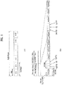
- FIG. 1(a) illustrates the type-1 radio frame structure.
- a downlink radio frame is divided into 10 subframes. Each subframe is further divided into two slots in the time domain.
- a unit time during which one subframe is transmitted is defined as a Transmission Time Interval (TTI).
- TTI Transmission Time Interval
- one subframe may be 1ms in duration and one slot may be 0.5ms in duration.
- a slot includes a plurality of OFDM symbols in the time domain and a plurality of Resource Blocks (RBs) in the frequency domain.
- RBs Resource Blocks
- an OFDM symbol represents one symbol period.
- An OFDM symbol may be referred to as an SC-FDMA symbol or symbol period.
- An RB is a resource allocation unit including a plurality of contiguous subcarriers in a slot.
- the number of OFDM symbols in one slot may vary depending on a Cyclic Prefix (CP) configuration.
- CP Cyclic Prefix
- the normal CP one slot includes 7 OFDM symbols.
- the extended CP the length of one OFDM symbol is increased and thus the number of OFDM symbols in a slot is smaller than in the case of the normal CP.
- the extended CP for example, 6 OFDM symbols may be included in one slot.
- the extended CP may be used to further decrease Inter-Symbol Interference (ISI).
- ISI Inter-Symbol Interference
- one subframe includes 14 OFDM symbols because one slot includes 7 OFDM symbols.
- the first two or three OFDM symbols of each subframe may be allocated to a Physical Downlink Control CHannel (PDCCH) and the other OFDM symbols may be allocated to a Physical Downlink Shared Channel (PDSCH).
- PDCCH Physical Downlink Control CHannel
- PDSCH Physical Downlink Shared Channel
- FIG. 1(b) illustrates the type-2 radio frame structure.
- a type-2 radio frame includes two half frames, each having 5 subframes, a Downlink Pilot Time Slot (DwPTS), a Guard Period (GP), and an Uplink Pilot Time Slot (UpPTS). Each subframe is divided into two slots.
- the DwPTS is used for initial cell search, synchronization, or channel estimation at a UE.
- the UpPTS is used for channel estimation and acquisition of uplink transmission synchronization to a UE at an eNB.
- the GP is a period between an uplink and a downlink, which eliminates uplink interference caused by multipath delay of a downlink signal.
- One subframe includes two slots irrespective of the type of a radio frame.
- radio frame structures are purely exemplary and thus it is to be noted that the number of subframes in a radio frame, the number of slots in a subframe, or the number of symbols in a slot may vary.
- FIG. 2 illustrates the structure of a downlink resource grid for the duration of one downlink slot.
- a downlink slot includes 7 OFDM symbols in the time domain and an RB includes 12 subcarriers in the frequency domain, which does not limit the scope of the present invention.
- a downlink slot may include 7 OFDM symbols in the case of the normal CP, whereas a downlink slot may include 6 OFDM symbols in the case of the extended CP.
- Each element of the resource grid is referred to as a Resource Element (RE).
- An RB includes 12x7 REs.
- the number of RBs in a downlink slot, NDL depends on a downlink transmission bandwidth.
- An uplink slot may have the same structure as a downlink slot.
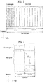
- FIG. 3 illustrates the structure of a downlink subframe.
- Up to three OFDM symbols at the start of the first slot in a downlink subframe are used for a control region to which control channels are allocated and the other OFDM symbols of the downlink subframe are used for a data region to which a PDSCH is allocated.
- Downlink control channels used in the 3GPP LTE system include a Physical Control Format Indicator CHannel (PCFICH), a Physical Downlink Control CHannel (PDCCH), and a Physical Hybrid automatic repeat request (HARQ) Indicator CHannel (PHICH).
- PCFICH Physical Control Format Indicator CHannel
- PDCH Physical Downlink Control CHannel
- HARQ Physical Hybrid automatic repeat request
- PHICH Physical Hybrid automatic repeat request
- the PHICH delivers an HARQ ACKnowledgment/Negative ACKnowledgment (ACK/NACK) signal in response to an uplink transmission.
- Control information carried on the PDCCH is called Downlink Control Information (DCI).
- DCI transports uplink or downlink scheduling information, or uplink transmission power control commands for UE groups.
- the PDCCH delivers information about resource allocation and a transport format for a Downlink Shared CHannel (DL-SCH), resource allocation information about an Uplink Shared CHannel (UL-SCH), paging information of a Paging CHannel (PCH), system information on the DL-SCH, information about resource allocation for a higher-layer control message such as a Random Access Response transmitted on the PDSCH, a set of transmission power control commands for individual UEs of a UE group, transmission power control information, Voice Over Internet Protocol (VoIP) activation information, etc.
- a plurality of PDCCHs may be transmitted in the control region.
- a UE may monitor a plurality of PDCCHs.
- a PDCCH is formed by aggregating one or more consecutive Control Channel Elements (CCEs).
- a CCE is a logical allocation unit used to provide a PDCCH at a coding rate based on the state of a radio channel.
- a CCE includes a plurality of RE groups.
- the format of a PDCCH and the number of available bits for the PDCCH are determined according to the correlation between the number of CCEs and a coding rate provided by the CCEs.
- An eNB determines the PDCCH format according to DCI transmitted to a UE and adds a Cyclic Redundancy Check (CRC) to control information.
- the CRC is masked by an Identifier (ID) known as a Radio Network Temporary Identifier (RNTI) according to the owner or usage of the PDCCH.
- ID Identifier
- RNTI Radio Network Temporary Identifier
- the PDCCH is directed to a specific UE, its CRC may be masked by a cell-RNTI (C-RNTI) of the UE. If the PDCCH is for a paging message, the CRC of the PDCCH may be masked by a Paging Indicator Identifier (P-RNTI). If the PDCCH carries system information, particularly, a System Information Block (SIB), its CRC may be masked by a system information ID and a System Information RNTI (SI-RNTI). To indicate that the PDCCH carries a Random Access Response in response to a Random Access Preamble transmitted by a UE, its CRC may be masked by a Random Access-RNTI (RA-RNTI).
- SIB System Information Block
- SI-RNTI System Information RNTI
- RA-RNTI Random Access-RNTI
- FIG. 4 illustrates the structure of an uplink subframe.
- An uplink subframe may be divided into a control region and a data region in the frequency domain.
- a Physical Uplink Control CHannel (PUCCH) carrying uplink control information is allocated to the control region and a Physical Uplink Shared Channel (PUSCH) carrying user data is allocated to the data region.
- PUCCH Physical Uplink Control CHannel
- PUSCH Physical Uplink Shared Channel
- a UE does not transmit a PUSCH and a PUCCH simultaneously.
- a PUCCH for a UE is allocated to an RB pair in a subframe. The RBs of the RB pair occupy different subcarriers in two slots. Thus it is said that the RB pair allocated to the PUCCH is frequency-hopped over a slot boundary.
- RSs Reference Signals
- a Packet is transmitted on a radio channel.
- the Packet may be distorted during the transmission.
- a receiver should compensate for the distortion of the received signal using channel information.
- a transmitter transmits a signal known to both the transmitter and the receiver and the receiver acquires knowledge of channel information based on the distortion of the signal received on the radio channel. This signal is called a pilot signal or an RS.
- Tx Transmission
- Rx Reception
- the RSs may be divided into downlink RSs and uplink RSs.
- the uplink RSs include:
- the downlink RSs are categorized into:
- RSs may also be divided into two types according to their purposes: RS for channel information acquisition and RS for data demodulation. Since its purpose lies in that a UE acquires downlink channel information, the former should be transmitted in a broad band and received even by a UE that does not receive downlink data in a specific subframe. This RS is also used in a situation like handover. The latter is an RS that an eNB transmits along with downlink data in specific resources. A UE can demodulate the data by measuring a channel using the RS. This RS should be transmitted in a data transmission area.
- FIG. 5 is a diagram illustrating a configuration of a wireless communication system having multiple antennas.
- the transfer rate may be theoretically increased by a product of a maximum transfer rate Ro upon utilization of a single antenna and a rate increase ratio Ri.
- transmit powers can be set different from each other for individual pieces of transmission information s 1 , s 1 , ⁇ , s N T , respectively. If the transmit powers are set to P 1 , P 2 , ⁇ , P N T , respectively, the transmission information with adjusted transmit powers can be represented as Equation 3.
- ⁇ can be represented as Equation 4 using diagonal matrix P of the transmission power.
- s ⁇ P 1 0 P 2 ⁇ 0 P N T
- s 1 s 2 ⁇ s N T Ps
- x 1 , x 2 , ⁇ , x N T can be expressed by using the vector X as follows.
- W ij denotes a weight between an i th transmit antenna and j th information. W is also called a precoding matrix.
- channels are modeled in the MIMO wireless communication system, the channels may be distinguished according to transmit/receive antenna indexes.
- a channel from the transmit antenna j to the receive antenna i is denoted by h ij .
- h ij it is noted that the indexes of the receive antennas precede the indexes of the transmit antennas in view of the order of indexes.
- FIG. 5(b) is a diagram illustrating channels from the NT transmit antennas to the receive antenna i.
- the channels may be combined and expressed in the form of a vector and a matrix.
- AWGN Additional White Gaussian Noise
- the received signals can be expressed as follows.
- the number of rows and columns of the channel matrix H indicating the channel state is determined by the number of transmit and receive antennas.
- the number of rows of the channel matrix H is equal to the number NR of receive antennas and the number of columns thereof is equal to the number NR of transmit antennas. That is, the channel matrix H is an NR ⁇ NT matrix.
- the rank of the matrix is defined by the smaller of the number of rows and the number of columns, which are independent from each other. Accordingly, the rank of the matrix is not greater than the number of rows or columns.
- the rank rank ( H ) of the channel matrix H is restricted as follows. rank H ⁇ min N T N R
- the rank of a matrix can also be defined as the number of non-zero Eigen values when the matrix is Eigen-value-decomposed.
- the rank of a matrix can be defined as the number of non-zero singular values when the matrix is singular-value-decomposed.
- the physical meaning of the rank of a channel matrix can be the maximum number of channels through which different pieces of information can be transmitted.
- 'rank' for MIMO transmission indicates the number of paths capable of sending signals independently on specific time and frequency resources and 'number of layers' indicates the number of signal streams transmitted through the respective paths.
- a transmitting end transmits the number of layers corresponding to the rank number, one rank has the same meaning of the layer number unless mentioned specially.
- some nodes may transmit a D2D Synchronization Signal (D2DSS) and the remaining UEs may transmit and receive signals in synchronization with the D2DSS.
- D2DSS D2D Synchronization Signal
- D2DSSs may include a Primary D2DSS (PD2DSS) or a Primary Sidelink Synchronization Signal (PSSS) and a Secondary D2DSS (SD2DSS) or a Secondary Sidelink Synchronization Signal (SSSS).
- the PD2DSS may be configured to have a similar/modified/repeated structure of a Zadoff-chu sequence of a predetermined length or a Primary Synchronization Signal (PSS).
- PSS Primary Synchronization Signal
- the PD2DSS may use a different Zadoff-chu root index (e.g., 26, 37).
- the SD2DSS may be configured to have a similar/modified/repeated structure of an M-sequence or a Secondary Synchronization Signal (SSS).
- SSS Secondary Synchronization Signal
- the eNB serves as an SRN and the D2DSS is a PSS/SSS.
- the PD2DSS/SD2DSS follows UL subcarrier mapping scheme.
- FIG. 6 shows a subframe in which a D2D synchronization signal is transmitted.
- a Physical D2D Synchronization Channel may be a (broadcast) channel carrying basic (system) information that a UE should first obtain before D2D signal transmission and reception (e.g., D2DSS-related information, a Duplex Mode (DM), a TDD UL/DL configuration, a resource pool-related information, the type of an application related to the D2DSS, etc.).
- the PD2DSCH may be transmitted in the same subframe as the D2DSS or in a subframe subsequent to the frame carrying the D2DSS.
- a DMRS can be used to demodulate the PD2DSCH.
- the SRN may be a node that transmits a D2DSS and a PD2DSCH.
- the D2DSS may be a specific sequence and the PD2DSCH may be a sequence representing specific information or a codeword produced by predetermined channel coding.
- the SRN may be an eNB or a specific D2D UE. In the case of partial network coverage or out of network coverage, the SRN may be a UE.
- a D2DSS may be relayed for D2D communication with an out-of-coverage UE.
- the D2DSS may be relayed over multiple hops.
- relay of an SS covers transmission of a D2DSS in a separate format according to a SS reception time as well as direct Amplify-and-Forward (AF)-relay of an SS transmitted by an eNB.
- AF direct Amplify-and-Forward
- an in-coverage UE may communicate directly with an out-of-coverage UE.
- FIG. 8 shows an example of a UE1, a UE2 and a resource pool used by the UE1 and the UE2 performing D2D communication.
- a UE corresponds to a terminal or such a network device as an eNB transmitting and receiving a signal according to a D2D communication scheme.
- a UE selects a resource unit corresponding to a specific resource from a resource pool corresponding to a set of resources and the UE transmits a D2D signal using the selected resource unit.
- a UE2 corresponding to a reception UE receives a configuration of a resource pool in which the UE1 is able to transmit a signal and detects a signal of the UE1 in the resource pool.
- a resource pool includes a plurality of resource units.
- a UE selects one or more resource units from among a plurality of the resource units and may be able to use the selected resource unit(s) for D2D signal transmission.
- FIG. 8 (b) shows an example of configuring a resource unit. Referring to FIG.
- a resource pool can be repeated with a period of N T subframes.
- one resource unit may periodically and repeatedly appear.
- an index of a physical resource unit to which a logical resource unit is mapped may change with a predetermined pattern according to time to obtain a diversity gain in time domain and/or frequency domain.
- a resource pool may correspond to a set of resource units capable of being used by a UE intending to transmit a D2D signal.
- a resource pool can be classified into various types. First of all, the resource pool can be classified according to contents of a D2D signal transmitted via each resource pool. For example, the contents of the D2D signal can be classified into various signals and a separate resource pool can be configured according to each of the contents.
- the contents of the D2D signal may include SA (scheduling assignment), a D2D data channel, and a discovery channel.
- the SA may correspond to a signal including information on a resource position of a D2D data channel, information on MCS (modulation and coding scheme) necessary for modulating and demodulating a data channel, information on a MIMO transmission scheme, information on TA (timing advance), and the like.
- the SA signal can be transmitted on an identical resource unit in a manner of being multiplexed with D2D data.
- an SA resource pool may correspond to a pool of resources that an SA and D2D data are transmitted in a manner of being multiplexed.
- the SA signal can also be referred to as a D2D control channel or a PSCCH (physical sidelink control channel).
- the D2D data channel (or, PSSCH (physical sidelink shared channel)) corresponds to a resource pool used by a transmission UE to transmit user data. If an SA and a D2D data are transmitted in a manner of being multiplexed in an identical resource unit, D2D data channel except SA information can be transmitted only in a resource pool for the D2D data channel.
- resource elements which are used to transmit SA information in a specific resource unit of an SA resource pool, can also be used for transmitting D2D data in a D2D data channel resource pool.
- the discovery channel may correspond to a resource pool for a message that enables a neighboring UE to discover transmission UE transmitting information such as ID of the UE, and the like.
- contents of D2D signal are identical to each other, it may use a different resource pool according to a transmission/reception attribute of the D2D signal.
- the D2D data channel or the discovery signal can be classified into a different resource pool according to a transmission timing determination scheme (e.g., whether a D2D signal is transmitted at the time of receiving a synchronization reference signal or the timing to which a prescribed timing advance is added) of a D2D signal, a resource allocation scheme (e.g., whether a transmission resource of an individual signal is designated by an eNB or an individual transmission UE selects an individual signal transmission resource from a pool), a signal format (e.g., number of symbols occupied by a D2D signal in a subframe, number of subframes used for transmitting a D2D signal), signal strength from an eNB, strength of transmit power of a D2D UE, and the like.
- a transmission timing determination scheme e.g., whether a D2D signal is transmitted at the time of
- a method for an eNB to directly designate a transmission resource of a D2D transmission UE is referred to as a mode 1. If a transmission resource region is configured in advance or an eNB designates the transmission resource region and a UE directly selects a transmission resource from the transmission resource region, it is referred to as a mode 2. In case of performing D2D discovery, if an eNB directly indicates a resource, it is referred to as a type 2. If a UE directly selects a transmission resource from a predetermined resource region or a resource region indicated by the eNB, it is referred to as a type 1.
- a mode 1 UE can transmit an SA signal (or, a D2D control signal, SCI (sidelink control information)) via a resource configured by an eNB.
- a mode 2 UE receives a configured resource to be used for D2D transmission.
- the mode 2 UE can transmit SA by selecting a time frequency resource from the configured resource.
- the SA period can be defined as FIG. 9 .
- a first SA period can start at a subframe apart from a specific system frame as much as a prescribed offset (SAOffsetIndicator) indicated by higher layer signaling.
- Each SA period can include an SA resource pool and a subframe pool for transmitting D2D data.
- the SA resource pool can include subframes ranging from a first subframe of an SA period to the last subframe among subframes indicated by a subframe bitmap (saSubframeBitmap) to transmit SA.
- T-RPT time-resource pattern for transmission or TRP(time-resource pattern)
- TRPT time-resource pattern for transmission or TRP(time-resource pattern)
- the T-RPT can be repeatedly applied and the lastly applied T-RPT can be applied in a manner of being truncated as many as the number of remaining subframes.
- a method of transmitting a discovery signal is explained according to one embodiment of the present invention based on the aforementioned description, a legacy LTE standard document, and a known technology.
- a length of a discovery message except a CRC corresponds to 232 bits.
- a new discovery format can be defined or a discovery message can be transmitted via a communication channel (PSSCH or PSCCH) (hereinafter, it can be referred to as DTC).
- PSSCH communication channel
- PSCCH PSCCH
- each of DTC embodiments can be independently used.
- at least two or more embodiments can be used in an aggregated form.
- a PSCCH format defined for DTC can be transmitted in a separate resource pool defined for the DTC in a form that a DTC embodiment 2 and a DT embodiment 3 are combined with each other.
- a discovery signal (MAC PDU of a discovery message) can be transmitted in a partial transmission opportunity only in an SA period.
- MAC PDU of a discovery message can be transmitted in a partial transmission opportunity only in an SA period.
- PSSCH D2D data
- a part of the TRP can be used for discovery transmission.
- a part of bits of the TRP can be differently used to indicate discovery.
- the UE determines a sub frame pool for transmitting data and applies a TRP (time resource pattern) bitmap to the subframe pool to determine a subframe set for transmitting a D2D signal.
- the UE transmits a discovery message in a subframe corresponding to the n number of bits of the TRP bitmap and may transmit no signal or D2D data in a subframe corresponding to the remaining bits of the TRP bitmap except the n number of bits.
- a reception UE may be necessary to have a method for a reception UE to identify a discovery signal transmitted on PSSCH.
- a CRC mask of the PSCCH is differently configured when a discovery message is transmitted and (only) a data is transmitted.
- the reception UE checks the CRC of the PSCCH, the reception UE is able to recognize that a discovery message is transmitted in a subframe corresponding to the n number of bits (of a subframe in which data is transmitted) of the PSCCH.
- a DMRS and/or a scrambling sequence can be differently configured when a discovery message is transmitted and (only) a data is transmitted.
- a DMRS of PSCCH for transmitting a discovery message, and/or a DMRS of PSCCH for transmitting a scrambling sequence and data, and/or a scrambling sequence may different from each other.
- the reception UE checks the DMRS and/or the scrambling sequence, the reception UE is able to identify whether the PSCCH is used for transmitting a discovery message or data.
- a discovery message when a discovery message is transmitted, it may use a predetermined MCS or an RB size.
- a discovery signal is transmitted in an RB of a predetermined size only in a subframe corresponding to the n number of bits.
- it may use a state not used in communication for MCS or an RB size to indicate that a discovery signal is transmitted in the n number of subframes corresponding to a part of the PSSCH.
- a CRC mask used for a subframe corresponding to the n number of bits may be different from a CRC mask used for a subframe corresponding to the remaining bits.
- a CRC mask of PSCCH is differently configured when a discovery message is transmitted and a data is transmitted. In this case, if the reception UE checks the CRC, the reception UE is able to distinguish the subframe corresponding to the n number of bits from the subframe corresponding to the remaining bits.
- a DMRS and/or a scrambling sequence can be differently configured when a discovery message is transmitted and a data is transmitted.
- a DMRS sequence transmitted in a subframe corresponding to the n number of bits may be different from a DMRS sequence transmitted in a subframe corresponding to the remaining bits.
- the reception UE checks a DMRS sequence the reception UE is able to distinguish the subframe corresponding to the n number of bits from the subframe corresponding to the remaining bits.
- a discovery message when a discovery message is transmitted, it may use a predetermined MCS or an RB size.
- a discovery signal is transmitted in an RB of a predetermined size only in a subframe corresponding to the n number of bits.
- a discovery signal can be transmitted at the first N number of transmission opportunities only within an SA period. Or, it may be able to UE-specifically distinguish a subframe in which a discovery signal is transmitted in time.
- a transmission opportunity at which a discovery message is transmitted can be configured by a different position between UEs. In this case, if all UEs transmit a discovery message at a common position within an SA period, a reception UE can get rid of a constraint that the reception UE is unable to receive all discovery signals. And, it may be able to configure UEs to receive a mutual discovery message by distributing subframes (time resource) in which a discovery message is transmitted between the UEs.
- a UE A transmitting a discovery message can transmit the discovery message from a first transmission opportunity to an N th transmission opportunity among transmission opportunities within an SA period.
- a UE B can transmit a discovery message from an (N+1) th transmission opportunity to a 2N th transmission opportunity within an SA period.
- it may use a UE-specific ID or a UE group-specific ID such as an ID of a UE, an L2 SA ID, a discovery ID, and the like.
- a position of the n number of bits can be determined by one selected from the group consisting of an ID, an L2 SA (scheduling assignment) ID, and a discovery ID.
- the positon can be determined by a combination of two or more IDs.
- a UE can randomly determine a position at which a discovery message is transmitted within an SA period. For example, it may be able to determine a rule that transmission opportunities within an SA period are divided by 4, a random number is selected from among numbers within quotient, and a discovery message is transmitted at a transmission opportunity corresponding to the selected random number.
- a UE in the TRP bitmap, a UE can randomly determine a position of the n number of bits from among positive integers equal to or less than quotient resulted from dividing the TRP bitmap by 4.
- a reception UE in order to make a reception UE clearly know a subframe position in which a discovery message of a specific UE is transmitted, it may assign a different PSCCH (destination) ID between UEs.
- PSCCH IDs are assigned for DTC and a discovery signal is configured to be transmitted at a different PSSCH subframe position for each of a plurality of the PSCCH IDs.
- PSCCH is transmitted in a manner of including a destination (group) ID (L2 ID) of the PSCCH
- L2 ID destination UE group ID
- a discovery signal when transmitted via the PSCCH, it may be able to configure all UEs or a plurality of destination groups to receive the ID included in the PSCCH or it may define a separate PSCCH format to transmit new information by including the information in the newly defined PSCCH format.
- it may be able to group-commonly configure the ID included in the PSCCH.
- a legacy 1RB PSCCH format 0 can be maintained.
- an ID corresponds to a specific state (e.g., all zero / all one), it may be able to determine a rule that all UEs receive PSCCH indicated by corresponding PSCCH.
- a legacy field e.g., an MCS field and/or a frequency resource indication field
- a legacy field can be fixed by a specific state or can be used for the usage of indicating different information.
- the MCS field and/or the frequency resource field can indicate different information or can be fixed by a specific state without being used.
- a reception UE checks the MCS field and/or the frequency resource field fixed by a specific state and may be able to recognize that the PSCCH is transmitted for the DTC. And, although the ID included in the PSCCH is not a destination group ID of the reception UE, the reception UE can receive a packet for discovery reception.
- a TA field can be used for the usage of a CRC by fixing the TA field by 0 all the time.
- an RB size can be determined from among the N number of limited candidates. In this case, most part of the frequency resource indication field is not used and can be used for a different usage.
- modulation is fixed by QPSK and the MCS field can be used for the usage of indicating different information. For example, since 64QAM is not used in current 3GPP Rel. 12/13 D2D, a part of 64 QAM states can be used for the usage of indicating DTC.
- a combination of a plurality of fields can indicate that PSCCH is used for DTC.
- MCS may use either a state corresponding to 64QAM or a reserved state and a partial state of the frequency resource indication field can indicate that the PSCCH is used for the DTC.
- a network can transmit a signal to a UE via physical layer signaling or higher layer signaling to indicate a usage of PSCCH and/or a PSSCH pool. Or, the information can be determined in advance according to each resource pool.
- a new PSCCH format may be able to define a new PSCCH format to have an RB size identical to an RB size of the legacy 1 RB PSCCH format and have a field configuration different from a field configuration of the legacy 1 RB PSCCH format.
- it may be able to define a PSCCH format of a higher coding rate in a manner of eliminating a partial field from the legacy PSSCH format or adding a new field to the legacy PSSCH format.
- MCS is used in a manner of being fixed and an MCS field and/or an ID field can be eliminated or fixed by a specific state.
- a TA field can be eliminated or fixed by a specific state (all zero). In particular, since the TA field is long (11 bits), if the TA field is eliminated, it may be able to obtain a considerable amount of coding gain.
- a CRC can be differently set to the PSSCH format 0 and a format for DTC to differently perform field interpretation.
- PSCCH format for DTC. For example, it may introduce PSCCH of 2 RBs or 4 RBs. It may be able to configure a plurality of group destination IDs to receive PSSCH by adding a plurality of ID fields. If DMRS measurement is performed on a lengthened RB, since the number of samples increases in frequency domain, it may be able to obtain a measurement result in a shorter time period.
- PSCCH for DTC can introduce CRC masking different from a PSCCH format 0 irrespective of a length or a field configuration of a format.
- a reception UE can distinguish the PSCCH format 0 from the PSCCH for DTC by checking a CRC.
- the PSCCH format for DTC is identical to a legacy PSCCH format, the reception UE can distinguish formats from each other without additional blind decoding.
- the PSCCH format newly defined for DTC can configure CRC masking with a specific bit state (e.g., (1,0,1,0,..., 1,0,1,0)).
- the PSCCH format for DTC may use two CRC masking different from each other for the legacy PSCCH format.
- a DMRS or a scrambling sequence generated for PSCCH for DTC can be configured in a manner of being different from a PSCCH format 0. For example, assume a case that a pool of the PSCCH format 0 is partially overlapped with a pool in which the PSCCH format for DTC is transmitted.
- PSCCHs of the same size are decoded, since the same DMRS is used, SFN (single frequency network) transmission is performed on a DMRS of PSCCH for discovery and a DMRS of PSCCH for communication (in other word, since DMRS sequences for transmitting a signal of a different purpose are the same, if the DMRS sequences are transmitted in a manner of being overlapped, it is difficult to distinguish DMRSs from each other). As a result, no signal can be properly decoded. In this case, it may be able to separate channels from each other by distinguishing DMRS sequences or scrambling sequences from each other according to a purpose to perform decoding separately.
- SFN single frequency network
- Table 1 in the following shows factors used for generating a DMRS of a legacy PSCCH/PSSCH and a scrambling sequence.
- Scrambling DMRS base s equence DM RS Cell ID RNTI Slot number Codeword index Group hopping Sequence hopping Delta shift Cell ID CS
- SA 510 Independent of UE ID Fixed to 0 Independent of the slot number Fixed to 0 Fixed to 0 Disabled Disabled 0 510 0 Fixed to [1 1]
- SA 510 Independent of UE ID Fixed to 0 Independent of the slot number Fixed to 0 Fixed to 0 Disabled Disabled 0 510 0 Fixed to [11]
- DATA 510 SA ID FFS Fixed to 0 Enabled Disabled 0 SA ID By SA ID bit 1, 2, 3 by SA ID bit 0
- a UE transmitting PSCCH/PSSCH for DTC may use a different value (e.g., 511) rather than 510 for a DMRS and a cell ID part of scrambling.
- a DMRS sequence is generated using an SA ID in PSSCH.
- the DMRS sequence may use a predetermined ID or an ID for DTC.
- CS/OCC of PSSCH may use a separate ID for DTC instead of a group destination ID.
- Each of the aforementioned embodiments can be used for a case of configuring a separate PSCCH resource pool. Yet, each of the aforementioned embodiments can be used for a pool of a legacy PSCCH format 0 as well.
- a PSCCH resource pool can be divided into a plurality of sub-pools. For example, it may be able to configure a resource for transmitting a new PSCCH format in a partial resource region of frequency domain, a partial resource region of time domain, or a partial resource region of time-frequency combination.
- a frequency resource is divided into the N number of regions and the M ( ⁇ N) number of regions among the N number of regions can be configured as regions in which PSCCH for transmitting DTC is transmitted.
- a part of subframes can be configured as a subframe for transmitting PSCCH for DTC.
- a part of a combination between a subframe (time) and a subband (frequency) can be configured as a resource for transmitting PSCCH for DTC.
- a part of SA resources can be configured as a resource for transmitting DTC.
- a PSSCH (data) region can also be configured by one of the aforementioned schemes (time, frequency, time + frequency).
- Measurement example 1 measuring reception power applied to DMRS of PSCCH
- all UEs are configured to use the same DMRS.
- DMRS averaging is performed between UEs, it is preferable to perform the averaging on DMRSs of which L2 ID is the same or DMRSs of which a source ID is the same only.
- a separate PSCCH pool or a sub-pool is configured for DTC and an ID of PSCCH includes all or a part of a source ID component in a corresponding region, it may be able to perform measurement averaging between DMRSs of which a source ID is the same.
- Measurement example 2 measuring reception power applied to DMRS of PSSCH
- a reception UE is able to know a position at which PSSCH is transmitted using a TRP indicated by PSCCH. In this case, it is able to measure reception power of a DMRS of the position at which the PSSCH is transmitted. Yet, a bandwidth of the PSCCH may change in every SA period. The bandwidth of the PSCCH can be measured only when averaging is performed within an SA period. If averaging is performed between SA periods, the averaging can be performed by normalizing an RB size.
- 4RB PSSCH when 4RB PSSCH is transmitted in an SA period #n and 6RB PSSCH is transmitted in an SA period #n+1, it may add up measurement values normalized by 1 RB. This is the average measurement per sample performed by normalizing measurement using the number of samples used for the measurement. In case of the latter case, averaging is performed on measurement irrespective of the number of samples. (Or, it may average a measurement result without normalizing.)
- Tx power may change in every SA period in mode 1.
- a UE may measure a genuine channel only except a Tx power value. Or, it may perform measurement averaging irrespective of transmit power.
- Tx UE since a Tx UE is able to increase transmit power for a wider discovery range, discovery measurement can be performed in consideration of the increased transmit power. In case of performing measurement while transmit power is excluded, it may have a merit in that it is able to measure a genuine channel state between D2D UEs.
- a TX UE may be able to regulate a TX UE to perform PSSCH TX of N RBs during at least prescribed time (e.g., X number of transmission opportunities) for reliable measurement.
- N corresponds to 6 RBs. If the N is determined by 6, it may be able to reduce UE complexity in the aspect of possibility capable of having a structure identical to PSBCH measurement. For example, if a BW on which PSSCH is transmitted is configured by 4 RBs, a DTC message or PSSCH of a certain number is transmitted using 6 RBs and the remaining PSSCH is transmitted using 4 RBs.
- a start point of frequency resource allocation is identical to a point indicated by PSCCH
- an end point is extended up to 6RB region when transmission is performed using 6 RBs.
- it may be difficult to perform transmission.
- it may perform transmission using 4RBs in a corresponding subframe.
- a region (X number of transmission opportunities) configured to perform transmission using N RB can be UE-commonly determined in advance. Or, it may determine a rule that transmission is performed at a different position according to a UE. For example, X numbers of transmissions are performed using N RB at a position interlocked with a UE ID among transmission opportunities within an SA period. In this case, a value of the X can be determined by a multiple of a repetition count in order not to change an RB size in the middle of transmitting MAC PDU. And, a start point of the X numbers of transmissions can be determined by a multiple unit of the repetition count.
- the X numbers of transmissions correspond to continuous transmission opportunities
- the X numbers of transmissions can be determined by a predetermined discontinuous pattern.
- a repetition count unit may have a continuous form in order not to change an RB size in the middle of transmitting an MAC PDU.
- the abovementioned methods can be selectively applied only when transmission is performed using RBs equal to or less than N RBs. Since the methods intend to secure measurement accuracy during a prescribed period when transmission is performed using a too small RB size, if an allocated RB size is big enough, since it is able to secure sufficient measurement accuracy, it is not necessary to perform an additional operation.
- a DMRS may be able to transmit a DMRS only using N RBs rather than differently configure a packet for PSSCH transmission.
- regions to which the DMRS is transmitted can be aligned on the basis of a start point, an end point, or a center RB of frequency resource allocation in which data is transmitted.
- a DMRS of a certain size is transmitted to secure measurement accuracy and a codeword of actual data is fixed by a size indicated by PSCCH to prevent encoding from being performed on various sizes.
- an RB size may change between a DTC packet and a data packet.
- measurement averaging can be performed on all packets or averaging can be performed on the DTC packet only. If measurement averaging is performed on all packets, it may apply the aforementioned normalization per RB size.
- Measurement example 3 performing averaging on same source ID only
- the example 3 is presented not as embodiments of the invention but as background art useful for understanding the invention.
- UEs different from each other perform DTC
- a reception UE performs averaging without a distinction of a UE, it is unable to perform relay UE selection.
- it is necessary to perform separate averaging according to a UE.
- it may use methods described in the following.
- PSSCH may perform averaging on PSSCH including the same ID on PSCCH.
- This method can be applied when it is able to set a source UE-specific ID to PSCCH.
- an ID included in PSCCH can be configured as a source ID. Having received the source ID, all UEs can perform measurement averaging on PSSCH/PSCCH having the same source ID only.
- a source ID is checked via a higher layer signal and measurement averaging can be performed on a DMRS of PSSCH/PSCCH having the same ID only. If a destination ID is continuously used as an ID of PSCCH or a UE group common ID is used, it may be difficult to identify a source UE via the PSCCH ID. In this case, it may consider a method that a source ID is obtained from higher layer and measurement averaging is performed on a DMRS of PSCCH/PSSCH only transmitted by a UE having the same source ID.
- PSCCH/PSSCH transmission may not be performed due to WAN or SLSS transmission.
- a DMRS of not transmitted PSCCH/PSSCH may have an incorrect measurement result.
- it may consider a method of performing averaging only when RSRP is equal to or greater than a prescribed threshold or a method of measuring (averaging) a DMRS included in CRC passed packets only. In this case, it may be able to determine a rule that the averaging is performed only when a CRC corresponds to a CRC transmitting a discovery message among the CRC passed packets.
- a memory for performing the measurement can be excessively increased.
- the maximum number of measurement values stored in the memory can be restricted to a prescribed number (the number can be UE-commonly determined by a specific value in advance or each UE may have different capability).
- a measurement result value can be discarded from the firstly measured value in FIFO (first input first output) scheme.
- it may be able to determine a rule that DTC of a relay UE preferentially stores a measurement value. If the DTC of the relay UE and DTC of a different purpose coexist, a measurement value of the relay UE is preferentially stored to help relay path selection in the future.
- Examples for the aforementioned proposed methods can also be included as one of implementation methods of the present invention. Hence, it is apparent that the examples are regarded as a sort of proposed schemes.
- the aforementioned proposed schemes can be independently implemented or can be implemented in a combined (aggregated) form of a part of the proposed schemes. It may be able to configure an eNB to inform a UE of information on whether to apply the proposed methods (information on rules of the proposed methods) via a predefined signal (e.g., physical layer signal or upper layer signal).
- a predefined signal e.g., physical layer signal or upper layer signal.
- FIG. 10 is a diagram for configurations of a transmitter and a receiver.
- a transmit point apparatus 10 may include a receive module 11, a transmit module 12, a processor 13, a memory 14, and a plurality of antennas 15.
- the antennas 15 represent the transmit point apparatus that supports MIMO transmission and reception.
- the receive module 11 may receive various signals, data and information from a UE on an uplink.
- the transmit module 12 may transmit various signals, data and information to a UE on a downlink.
- the processor 13 may control overall operation of the transmit point apparatus 10.
- the processor 13 of the transmit point apparatus 10 may perform processes necessary for the embodiments described above.
- the processor 13 of the transmit point apparatus 10 may function to operationally process information received by the transmit point apparatus 10 or information to be transmitted from the transmit point apparatus 10, and the memory 14, which may be replaced with an element such as a buffer (not shown), may store the processed information for a predetermined time.
- a UE 20 may include a receive module 21, a transmit module 22, a processor 23, a memory 24, and a plurality of antennas 25.
- the antennas 25 represent the UE that supports MIMO transmission and reception.
- the receive module 21 may receive various signals, data and information from an eNB on a downlink.
- the transmit module 22 may transmit various signals, data and information to an eNB on an uplink.
- the processor 23 may control overall operation of the UE 20.
- the processor 23 of the UE 20 may perform processes necessary for the embodiments described above.
- the processor 23 of the UE 20 may function to operationally process information received by the UE 20 or information to be transmitted from the UE 20, and the memory 24, which may be replaced with an element such as a buffer (not shown), may store the processed information for a predetermined time.
- the configurations of the transmit point apparatus and the UE as described above may be implemented such that the above-described embodiments can be independently applied or two or more thereof can be simultaneously applied, and description of redundant parts is omitted for clarity.
- Description of the transmit point apparatus 10 in FIG. 10 may be equally applied to a relay as a downlink transmitter or an uplink receiver, and description of the UE 20 may be equally applied to a relay as a downlink receiver or an uplink transmitter.
- the embodiments of the present invention may be implemented through various means, for example, hardware, firmware, software, or a combination thereof.
- a method according to embodiments of the present invention may be embodied as one or more application specific integrated circuits (ASICs), one or more digital signal processors (DSPs), one or more digital signal processing devices (DSPDs), one or more programmable logic devices (PLDs), one or more field programmable gate arrays (FPGAs), a processor, a controller, a microcontroller, a microprocessor, etc.
- ASICs application specific integrated circuits
- DSPs digital signal processors
- DSPDs digital signal processing devices
- PLDs programmable logic devices
- FPGAs field programmable gate arrays
- processor a controller, a microcontroller, a microprocessor, etc.
- a method according to embodiments of the present invention may be embodied as a module, a procedure, or a function that performs the functions or operations described above.
- Software code may be stored in a memory unit and executed by a processor.
- the memory unit is located at the interior or exterior of the processor and may transmit and receive data to and from the processor via various known means.
- the embodiments of the present invention can be applied to various mobile communication systems.
Description
- Following description relates to a wireless communication system, and more particularly, to a method of transmitting and receiving a discovery signal extended in D2D communication and an apparatus therefor.
- Wireless communication systems have been widely deployed to provide various types of communication services such as voice or data. In general, a wireless communication system is a multiple access system that supports communication of multiple users by sharing available system resources (a bandwidth, transmission power, etc.) among them. For example, multiple access systems include a Code Division Multiple Access (CDMA) system, a Frequency Division Multiple Access (FDMA) system, a Time Division Multiple Access (TDMA) system, an Orthogonal Frequency Division Multiple Access (OFDMA) system, a Single Carrier Frequency Division Multiple Access (SC-FDMA) system, and a Multi-Carrier Frequency Division Multiple Access (MC-FDMA) system.
- Device-to-Device (D2D) communication means a communication system for directly exchanging audio, data and the like between user equipments without passing through a base station (evolved NodeB: eNB) by establishing a direct link between the user equipments. D2D communication may include such a system as a UE-to-UE (user equipment-to-user equipment) communication, Peer-to-Peer communication and the like. And, the D2D communication system may be applicable to M2M (Machine-to-Machine) communication, MTC (Machine Type Communication) and the like.
- D2D communication is currently considered as one of schemes for setting a load put on a base station due to the rapidly increasing data traffic. For instance, according to D2D communication, unlike an existing wireless communication system, since data is exchanged between devices without passing through a base station, overload of a network can be reduced. Moreover, by introducing D2D communication, it is able to expect effects such as procedure reduction of a base station, power consumption reduction of devices involved in D2D, data transmission speed increase, reception capability increase of a network, load distribution, extension of cell coverage and the like.
- The document ("Considerations on ProSe public safety discovery", 3GPP DRAFT; R2-151461) outlines observations from which a proposal to extend the Rel-12 discovery mechanism and suggest SA2 constrain a size of discovery message is derived.
- The document ("UE-to-Network Relay Discovery", 3GPP DRAFT; R1-151865) outlines a possible solution on how to support of public safety discovery, with a particular emphasis on UE-to-Network relay discovery.
-
WO 2015/020448 A1 describes a method and apparatus for transmitting and receiving resource allocation information in a wireless communication system. In the document the method for transmitting resource allocation information in a base station (BS) is described to include allocating resources for each of one or more device-to-device (D2D) discovery resources pools, generating information about resources allocated for each of the one or more D2D discovery resource pools, and transmitting the generated information. -
US 2014/0328329 A1 describes a method including configuring one or multiple pools of Device-to-Device (D2D) communication resources by an eNodeB (eNB), signaling of the configured pool(s) of D2D communication resources by the eNB to a first User Equipment (UE) and a plurality of UEs using a common broadcast channel, sending a request for one or multiple D2D communication resources to an eNB by the first UE configured to transmit D2D messages, determining one or multiple resources for D2D communication by an eNB for the first UE, communicating D2D resource allocation information to the first UE, communicating D2D resource allocation information by the first UE to multiple UEs and transmitting D2D data by the first UE to multiple UEs. -
WO 2015/065015 A1 describes a method for transmission of a device-to-device (D2D) signal by a terminal in a wireless communication system. In the document the method is described to comprise receiving a location of resources, for transmitting a scheduling assignment, from a base station, and transmitting the scheduling assignment by means of the resources, wherein the scheduling assignment comprises information indicating a subframe, for transmitting a D2D-related signal in a scheduling assignment period that is subsequent to the subframe in which the scheduling assignment is transmitted. - A technical task of the present invention is to provide a method of transmitting a discovery signal including more information compared to a legacy discovery signal in a D2D communication.
- Technical tasks obtainable from the present invention are non-limited by the above-mentioned technical task. And, other unmentioned technical tasks can be clearly understood from the following description by those having ordinary skill in the technical field to which the present invention pertains.
- To achieve these and other advantages and in accordance with the purpose of the present invention, as embodied and broadly described, according to one embodiment, a method of transmitting a discovery signal by a user equipment in a wireless communication system and its preferred embodiments are provided as defined in the appended claims.
- According to the present invention, it is able to transmit an extended discovery signal while reducing blind decoding burden of a UE.
- Effects obtainable from the present invention are non-limited by the above mentioned effect. And, other unmentioned effects can be clearly understood from the following description by those having ordinary skill in the technical field to which the present invention pertains.
- The accompanying drawings, which are included to provide a further understanding of the invention and are incorporated in and constitute a part of this specification, illustrate embodiments of the invention and together with the description serve to explain the principles of the invention.
-
FIG. 1 is a diagram for a structure of a radio frame; -
FIG. 2 is a diagram for a resource grid in a downlink slot; -
FIG. 3 is a diagram for a structure of a downlink subframe; -
FIG. 4 is a diagram for a structure of an uplink subframe; -
FIG. 5 is a diagram for a configuration of a wireless communication system having multiple antennas; -
FIG. 6 is a diagram for a subframe in which a D2D synchronization signal is transmitted; -
FIG. 7 is a diagram for explaining relay of a D2D signal; -
FIG. 8 is a diagram for an example of a D2D resource pool for performing D2D communication; -
FIG. 9 is a diagram for explaining an SA period; -
FIG. 10 is a diagram for configurations of a transmitter and a receiver. - The embodiments of the present invention described hereinbelow are combinations of elements and features of the present invention. The elements or features may be considered selective unless otherwise mentioned. Each element or feature may be practiced without being combined with other elements or features. Further, an embodiment of the present invention may be constructed by combining parts of the elements and/or features. Operation orders described in embodiments of the present invention may be rearranged. Some constructions or features of any one embodiment may be included in another embodiment and may be replaced with corresponding constructions or features of another embodiment.
- In the embodiments of the present invention, a description is made, centering on a data transmission and reception relationship between a Base Station (BS) and a User Equipment (UE). The BS is a terminal node of a network, which communicates directly with a UE. In some cases, a specific operation described as performed by the BS may be performed by an upper node of the BS.
- Namely, it is apparent that, in a network comprised of a plurality of network nodes including a BS, various operations performed for communication with a UE may be performed by the BS or network nodes other than the BS. The term 'BS' may be replaced with the term 'fixed station', 'Node B', 'evolved Node B (eNode B or eNB)', 'Access Point (AP)', etc. The term 'relay' may be replaced with the term 'Relay Node (RN)' or 'Relay Station (RS)'. The term 'terminal' may be replaced with the term 'UE', 'Mobile Station (MS)', 'Mobile Subscriber Station (MSS)', 'Subscriber Station (SS)', etc.
- The term "cell", as used herein, may be applied to transmission and reception points such as a base station (eNB), sector, remote radio head (RRH) and relay, and may also be extensively used by a specific transmission/reception point to distinguish between component carriers.
- Specific terms used for the embodiments of the present invention are provided to help the understanding of the present invention. These specific terms may be replaced with other terms within the scope of the present invention.
- In some cases, to prevent the concept of the present invention from being ambiguous, structures and apparatuses of the known art will be omitted, or will be shown in the form of a block diagram based on main functions of each structure and apparatus. Also, wherever possible, the same reference numbers will be used throughout the drawings and the specification to refer to the same or like parts.
- The embodiments of the present invention can be supported by standard documents disclosed for at least one of wireless access systems, Institute of Electrical and Electronics Engineers (IEEE) 802, 3rd Generation Partnership Project (3GPP), 3GPP Long Term Evolution (3GPP LTE), LTE-Advanced (LTE-A), and 3GPP2. Steps or parts that are not described to clarify the technical features of the present invention can be supported by those documents. Further, all terms as set forth herein can be explained by the standard documents.
- Techniques described herein can be used in various wireless access systems such as Code Division Multiple Access (CDMA), Frequency Division Multiple Access (FDMA), Time Division Multiple Access (TDMA), Orthogonal Frequency Division Multiple Access (OFDMA), Single Carrier-Frequency Division Multiple Access (SC-FDMA), etc. CDMA may be implemented as a radio technology such as Universal Terrestrial Radio Access (UTRA) or CDMA2000. TDMA may be implemented as a radio technology such as Global System for Mobile communications (GSM)/General Packet Radio Service (GPRS)/Enhanced Data Rates for GSM Evolution (EDGE). OFDMA may be implemented as a radio technology such as IEEE 802.11 (Wi-Fi), IEEE 802.16 (WiMAX), IEEE 802.20, Evolved-UTRA (E-UTRA) etc. UTRA is a part of Universal Mobile Telecommunications System (UMTS). 3GPP LTE is a part of Evolved UMTS (E-UMTS) using E-UTRA. 3GPP LTE employs OFDMA for downlink and SC-FDMA for uplink. LTE-A is an evolution of 3GPP LTE. WiMAX can be described by the IEEE 802.16e standard (Wireless Metropolitan Area Network (WirelessMAN)-OFDMA Reference System) and the IEEE 802.16m standard (WirelessMAN-OFDMA Advanced System). For clarity, this application focuses on the 3GPP LTE and LTE-A systems. However, the technical features of the present invention are not limited thereto.
- With reference to
FIG. 1 , the structure of a radio frame will be described below. - In a cellular Orthogonal Frequency Division Multiplexing (OFDM) wireless Packet communication system, uplink and/or downlink data Packets are transmitted in subframes. One subframe is defined as a predetermined time period including a plurality of OFDM symbols. The 3GPP LTE standard supports a type-1 radio frame structure applicable to Frequency Division Duplex (FDD) and a type-2 radio frame structure applicable to Time Division Duplex (TDD).
-
FIG. 1(a) illustrates the type-1 radio frame structure. A downlink radio frame is divided into 10 subframes. Each subframe is further divided into two slots in the time domain. A unit time during which one subframe is transmitted is defined as a Transmission Time Interval (TTI). For example, one subframe may be 1ms in duration and one slot may be 0.5ms in duration. A slot includes a plurality of OFDM symbols in the time domain and a plurality of Resource Blocks (RBs) in the frequency domain. Because the 3GPP LTE system adopts OFDMA for downlink, an OFDM symbol represents one symbol period. An OFDM symbol may be referred to as an SC-FDMA symbol or symbol period. An RB is a resource allocation unit including a plurality of contiguous subcarriers in a slot. - The number of OFDM symbols in one slot may vary depending on a Cyclic Prefix (CP) configuration. There are two types of CPs: extended CP and normal CP. In the case of the normal CP, one slot includes 7 OFDM symbols. In the case of the extended CP, the length of one OFDM symbol is increased and thus the number of OFDM symbols in a slot is smaller than in the case of the normal CP. Thus when the extended CP is used, for example, 6 OFDM symbols may be included in one slot. If channel state gets poor, for example, during fast movement of a UE, the extended CP may be used to further decrease Inter-Symbol Interference (ISI).
- In the case of the normal CP, one subframe includes 14 OFDM symbols because one slot includes 7 OFDM symbols. The first two or three OFDM symbols of each subframe may be allocated to a Physical Downlink Control CHannel (PDCCH) and the other OFDM symbols may be allocated to a Physical Downlink Shared Channel (PDSCH).
-
FIG. 1(b) illustrates the type-2 radio frame structure. A type-2 radio frame includes two half frames, each having 5 subframes, a Downlink Pilot Time Slot (DwPTS), a Guard Period (GP), and an Uplink Pilot Time Slot (UpPTS). Each subframe is divided into two slots. The DwPTS is used for initial cell search, synchronization, or channel estimation at a UE. The UpPTS is used for channel estimation and acquisition of uplink transmission synchronization to a UE at an eNB. The GP is a period between an uplink and a downlink, which eliminates uplink interference caused by multipath delay of a downlink signal. One subframe includes two slots irrespective of the type of a radio frame. - The above-described radio frame structures are purely exemplary and thus it is to be noted that the number of subframes in a radio frame, the number of slots in a subframe, or the number of symbols in a slot may vary.
-
FIG. 2 illustrates the structure of a downlink resource grid for the duration of one downlink slot. A downlink slot includes 7 OFDM symbols in the time domain and an RB includes 12 subcarriers in the frequency domain, which does not limit the scope of the present invention. For example, a downlink slot may include 7 OFDM symbols in the case of the normal CP, whereas a downlink slot may include 6 OFDM symbols in the case of the extended CP. Each element of the resource grid is referred to as a Resource Element (RE). An RB includes 12x7 REs. The number of RBs in a downlink slot, NDL depends on a downlink transmission bandwidth. An uplink slot may have the same structure as a downlink slot. -
FIG. 3 illustrates the structure of a downlink subframe. Up to three OFDM symbols at the start of the first slot in a downlink subframe are used for a control region to which control channels are allocated and the other OFDM symbols of the downlink subframe are used for a data region to which a PDSCH is allocated. Downlink control channels used in the 3GPP LTE system include a Physical Control Format Indicator CHannel (PCFICH), a Physical Downlink Control CHannel (PDCCH), and a Physical Hybrid automatic repeat request (HARQ) Indicator CHannel (PHICH). The PCFICH is located in the first OFDM symbol of a subframe, carrying information about the number of OFDM symbols used for transmission of control channels in the subframe. The PHICH delivers an HARQ ACKnowledgment/Negative ACKnowledgment (ACK/NACK) signal in response to an uplink transmission. Control information carried on the PDCCH is called Downlink Control Information (DCI). The DCI transports uplink or downlink scheduling information, or uplink transmission power control commands for UE groups. The PDCCH delivers information about resource allocation and a transport format for a Downlink Shared CHannel (DL-SCH), resource allocation information about an Uplink Shared CHannel (UL-SCH), paging information of a Paging CHannel (PCH), system information on the DL-SCH, information about resource allocation for a higher-layer control message such as a Random Access Response transmitted on the PDSCH, a set of transmission power control commands for individual UEs of a UE group, transmission power control information, Voice Over Internet Protocol (VoIP) activation information, etc. A plurality of PDCCHs may be transmitted in the control region. A UE may monitor a plurality of PDCCHs. A PDCCH is formed by aggregating one or more consecutive Control Channel Elements (CCEs). A CCE is a logical allocation unit used to provide a PDCCH at a coding rate based on the state of a radio channel. A CCE includes a plurality of RE groups. The format of a PDCCH and the number of available bits for the PDCCH are determined according to the correlation between the number of CCEs and a coding rate provided by the CCEs. An eNB determines the PDCCH format according to DCI transmitted to a UE and adds a Cyclic Redundancy Check (CRC) to control information. The CRC is masked by an Identifier (ID) known as a Radio Network Temporary Identifier (RNTI) according to the owner or usage of the PDCCH. If the PDCCH is directed to a specific UE, its CRC may be masked by a cell-RNTI (C-RNTI) of the UE. If the PDCCH is for a paging message, the CRC of the PDCCH may be masked by a Paging Indicator Identifier (P-RNTI). If the PDCCH carries system information, particularly, a System Information Block (SIB), its CRC may be masked by a system information ID and a System Information RNTI (SI-RNTI). To indicate that the PDCCH carries a Random Access Response in response to a Random Access Preamble transmitted by a UE, its CRC may be masked by a Random Access-RNTI (RA-RNTI). -
FIG. 4 illustrates the structure of an uplink subframe. An uplink subframe may be divided into a control region and a data region in the frequency domain. A Physical Uplink Control CHannel (PUCCH) carrying uplink control information is allocated to the control region and a Physical Uplink Shared Channel (PUSCH) carrying user data is allocated to the data region. To maintain the property of a single carrier, a UE does not transmit a PUSCH and a PUCCH simultaneously. A PUCCH for a UE is allocated to an RB pair in a subframe. The RBs of the RB pair occupy different subcarriers in two slots. Thus it is said that the RB pair allocated to the PUCCH is frequency-hopped over a slot boundary. - In a wireless communication system, a Packet is transmitted on a radio channel. In view of the nature of the radio channel, the Packet may be distorted during the transmission. To receive the signal successfully, a receiver should compensate for the distortion of the received signal using channel information. Generally, to enable the receiver to acquire the channel information, a transmitter transmits a signal known to both the transmitter and the receiver and the receiver acquires knowledge of channel information based on the distortion of the signal received on the radio channel. This signal is called a pilot signal or an RS.
- In the case of data transmission and reception through multiple antennas, knowledge of channel states between Transmission (Tx) antennas and Reception (Rx) antennas is required for successful signal reception. Accordingly, an RS should be transmitted through each Tx antenna.
- RSs may be divided into downlink RSs and uplink RSs. In the current LTE system, the uplink RSs include:
- i) DeModulation-Reference Signal (DM-RS) used for channel estimation for coherent demodulation of information delivered on a PUSCH and a PUCCH; and
- ii) Sounding Reference Signal (SRS) used for an eNB or a network to measure the quality of an uplink channel in a different frequency.
- The downlink RSs are categorized into:
- i) Cell-specific Reference Signal (CRS) shared among all UEs of a cell;
- ii) UE-specific RS dedicated to a specific UE;
- iii) DM-RS used for coherent demodulation of a PDSCH, when the PDSCH is transmitted;
- iv) Channel State Information-Reference Signal (CSI-RS) carrying CSI, when downlink DM-RSs are transmitted;
- v) Multimedia Broadcast Single Frequency Network (MBSFN) RS used for coherent demodulation of a signal transmitted in MBSFN mode; and
- vi) positioning RS used to estimate geographical position information about a UE.
- RSs may also be divided into two types according to their purposes: RS for channel information acquisition and RS for data demodulation. Since its purpose lies in that a UE acquires downlink channel information, the former should be transmitted in a broad band and received even by a UE that does not receive downlink data in a specific subframe. This RS is also used in a situation like handover. The latter is an RS that an eNB transmits along with downlink data in specific resources. A UE can demodulate the data by measuring a channel using the RS. This RS should be transmitted in a data transmission area.
-
FIG. 5 is a diagram illustrating a configuration of a wireless communication system having multiple antennas. - As shown in
FIG. 5(a) , if the number of transmit antennas is increased to NT and the number of receive antennas is increased to NR, a theoretical channel transmission capacity is increased in proportion to the number of antennas, unlike the case where a plurality of antennas is used in only a transmitter or a receiver. Accordingly, it is possible to improve a transfer rate and to remarkably improve frequency efficiency. As the channel transmission capacity is increased, the transfer rate may be theoretically increased by a product of a maximum transfer rate Ro upon utilization of a single antenna and a rate increase ratio Ri.
- For instance, in an MIMO communication system, which uses 4 transmit antennas and 4 receive antennas, a
transmission rate 4 times higher than that of a single antenna system can be obtained. Since this theoretical capacity increase of the MIMO system has been proved in the middle of 90's, many ongoing efforts are made to various techniques to substantially improve a data transmission rate. In addition, these techniques are already adopted in part as standards for various wireless communications such as 3G mobile communication, next generation wireless LAN and the like. - The trends for the MIMO relevant studies are explained as follows. First of all, many ongoing efforts are made in various aspects to develop and research information theory study relevant to MIMO communication capacity calculations and the like in various channel configurations and multiple access environments, radio channel measurement and model derivation study for MIMO systems, spatiotemporal signal processing technique study for transmission reliability enhancement and transmission rate improvement and the like.
- In order to explain a communicating method in an MIMO system in detail, mathematical modeling can be represented as follows. It is assumed that there are NT transmit antennas and NR receive antennas.
- Regarding a transmitted signal, if there are NT transmit antennas, the maximum number of pieces of information that can be transmitted is NT. Hence, the transmission information can be represented as shown in
Equation 2.
- Meanwhile, transmit powers can be set different from each other for individual pieces of transmission information s 1, s 1,···, sN
T , respectively. If the transmit powers are set to P 1, P 2, ···, PNT , respectively, the transmission information with adjusted transmit powers can be represented asEquation 3.
- In addition, Ŝ can be represented as
Equation 4 using diagonal matrix P of the transmission power.
- Assuming a case of configuring NT transmitted signals x 1, x 2, ···, xN
T , which are actually transmitted, by applying weight matrix W to the information vector Ŝ having the adjusted transmit powers, the weight matrix W serves to appropriately distribute the transmission information to each antenna according to a transport channel state. x 1, x 2, ···, xNT can be expressed by using the vector X as follows.
- In
Equation 5, Wij denotes a weight between an ith transmit antenna and jth information. W is also called a precoding matrix. - If the NR receive antennas are present, respective received signals y 1, y 2, ···, yN
R of the antennas can be expressed as follows.
- If channels are modeled in the MIMO wireless communication system, the channels may be distinguished according to transmit/receive antenna indexes. A channel from the transmit antenna j to the receive antenna i is denoted by hij. In hij , it is noted that the indexes of the receive antennas precede the indexes of the transmit antennas in view of the order of indexes.
-
FIG. 5(b) is a diagram illustrating channels from the NT transmit antennas to the receive antenna i. The channels may be combined and expressed in the form of a vector and a matrix. InFIG. 5(b) , the channels from the NT transmit antennas to the receive antenna i can be expressed as follows.
- Accordingly, all channels from the NT transmit antennas to the NR receive antennas can be expressed as follows.

- An AWGN (Additive White Gaussian Noise) is added to the actual channels after a channel matrix H. The AWGN n 1, n 2, ···, nN
R respectively added to the NR receive antennas can be expressed as follows.
- Through the above-described mathematical modeling, the received signals can be expressed as follows.

- Meanwhile, the number of rows and columns of the channel matrix H indicating the channel state is determined by the number of transmit and receive antennas. The number of rows of the channel matrix H is equal to the number NR of receive antennas and the number of columns thereof is equal to the number NR of transmit antennas. That is, the channel matrix H is an NR×NT matrix.
- The rank of the matrix is defined by the smaller of the number of rows and the number of columns, which are independent from each other. Accordingly, the rank of the matrix is not greater than the number of rows or columns. The rank rank(H) of the channel matrix H is restricted as follows.

- Additionally, the rank of a matrix can also be defined as the number of non-zero Eigen values when the matrix is Eigen-value-decomposed. Similarly, the rank of a matrix can be defined as the number of non-zero singular values when the matrix is singular-value-decomposed. Accordingly, the physical meaning of the rank of a channel matrix can be the maximum number of channels through which different pieces of information can be transmitted.
- In the description of the present document, 'rank' for MIMO transmission indicates the number of paths capable of sending signals independently on specific time and frequency resources and 'number of layers' indicates the number of signal streams transmitted through the respective paths. Generally, since a transmitting end transmits the number of layers corresponding to the rank number, one rank has the same meaning of the layer number unless mentioned specially.
- Now, a description will be given of synchronization acquisition between UEs in D2D communication based on the foregoing description in the context of the legacy LTE/LTE-A system. In an OFDM system, if time/frequency synchronization is not acquired, the resulting Inter-Cell Interference (ICI) may make it impossible to multiplex different UEs in an OFDM signal. If each individual D2D UE acquires synchronization by transmitting and receiving a synchronization signal directly, this is inefficient. In a distributed node system such as a D2D communication system, therefore, a specific node may transmit a representative synchronization signal and the other UEs may acquire synchronization using the representative synchronization signal. In other words, some nodes (which may be an eNB, a UE, and a Synchronization Reference Node (SRN, also referred to as a synchronization source)) may transmit a D2D Synchronization Signal (D2DSS) and the remaining UEs may transmit and receive signals in synchronization with the D2DSS.
- D2DSSs may include a Primary D2DSS (PD2DSS) or a Primary Sidelink Synchronization Signal (PSSS) and a Secondary D2DSS (SD2DSS) or a Secondary Sidelink Synchronization Signal (SSSS). The PD2DSS may be configured to have a similar/modified/repeated structure of a Zadoff-chu sequence of a predetermined length or a Primary Synchronization Signal (PSS). Unlike a DL PSS, the PD2DSS may use a different Zadoff-chu root index (e.g., 26, 37). And, the SD2DSS may be configured to have a similar/modified/repeated structure of an M-sequence or a Secondary Synchronization Signal (SSS). If UEs synchronize their timing with an eNB, the eNB serves as an SRN and the D2DSS is a PSS/SSS. Unlike PSS/SSS of DL, the PD2DSS/SD2DSS follows UL subcarrier mapping scheme.
FIG. 6 shows a subframe in which a D2D synchronization signal is transmitted. A Physical D2D Synchronization Channel (PD2DSCH) may be a (broadcast) channel carrying basic (system) information that a UE should first obtain before D2D signal transmission and reception (e.g., D2DSS-related information, a Duplex Mode (DM), a TDD UL/DL configuration, a resource pool-related information, the type of an application related to the D2DSS, etc.). The PD2DSCH may be transmitted in the same subframe as the D2DSS or in a subframe subsequent to the frame carrying the D2DSS. A DMRS can be used to demodulate the PD2DSCH. - The SRN may be a node that transmits a D2DSS and a PD2DSCH. The D2DSS may be a specific sequence and the PD2DSCH may be a sequence representing specific information or a codeword produced by predetermined channel coding. The SRN may be an eNB or a specific D2D UE. In the case of partial network coverage or out of network coverage, the SRN may be a UE.
- In a situation illustrated in
FIG. 7 , a D2DSS may be relayed for D2D communication with an out-of-coverage UE. The D2DSS may be relayed over multiple hops. The following description is given with the appreciation that relay of an SS covers transmission of a D2DSS in a separate format according to a SS reception time as well as direct Amplify-and-Forward (AF)-relay of an SS transmitted by an eNB. As the D2DSS is relayed, an in-coverage UE may communicate directly with an out-of-coverage UE. -
FIG. 8 shows an example of a UE1, a UE2 and a resource pool used by the UE1 and the UE2 performing D2D communication. InFIG. 8 (a) , a UE corresponds to a terminal or such a network device as an eNB transmitting and receiving a signal according to a D2D communication scheme. A UE selects a resource unit corresponding to a specific resource from a resource pool corresponding to a set of resources and the UE transmits a D2D signal using the selected resource unit. A UE2 corresponding to a reception UE receives a configuration of a resource pool in which the UE1 is able to transmit a signal and detects a signal of the UE1 in the resource pool. In this case, if the UE1 is located at the inside of coverage of an eNB, the eNB can inform the UE1 of the resource pool. If the UE1 is located at the outside of coverage of the eNB, the resource pool can be informed by a different UE or can be determined by a predetermined resource. In general, a resource pool includes a plurality of resource units. A UE selects one or more resource units from among a plurality of the resource units and may be able to use the selected resource unit(s) for D2D signal transmission.FIG. 8 (b) shows an example of configuring a resource unit. Referring toFIG. 8 (b) , the entire frequency resources are divided into the NF number of resource units and the entire time resources are divided into the NT number of resource units. In particular, it is able to define NF ∗NT number of resource units in total. In particular, a resource pool can be repeated with a period of NT subframes. Specifically, as shown inFIG. 8 , one resource unit may periodically and repeatedly appear. Or, an index of a physical resource unit to which a logical resource unit is mapped may change with a predetermined pattern according to time to obtain a diversity gain in time domain and/or frequency domain. In this resource unit structure, a resource pool may correspond to a set of resource units capable of being used by a UE intending to transmit a D2D signal. - A resource pool can be classified into various types. First of all, the resource pool can be classified according to contents of a D2D signal transmitted via each resource pool. For example, the contents of the D2D signal can be classified into various signals and a separate resource pool can be configured according to each of the contents. The contents of the D2D signal may include SA (scheduling assignment), a D2D data channel, and a discovery channel. The SA may correspond to a signal including information on a resource position of a D2D data channel, information on MCS (modulation and coding scheme) necessary for modulating and demodulating a data channel, information on a MIMO transmission scheme, information on TA (timing advance), and the like. The SA signal can be transmitted on an identical resource unit in a manner of being multiplexed with D2D data. In this case, an SA resource pool may correspond to a pool of resources that an SA and D2D data are transmitted in a manner of being multiplexed. The SA signal can also be referred to as a D2D control channel or a PSCCH (physical sidelink control channel). The D2D data channel (or, PSSCH (physical sidelink shared channel)) corresponds to a resource pool used by a transmission UE to transmit user data. If an SA and a D2D data are transmitted in a manner of being multiplexed in an identical resource unit, D2D data channel except SA information can be transmitted only in a resource pool for the D2D data channel. In other word, resource elements (REs), which are used to transmit SA information in a specific resource unit of an SA resource pool, can also be used for transmitting D2D data in a D2D data channel resource pool. The discovery channel may correspond to a resource pool for a message that enables a neighboring UE to discover transmission UE transmitting information such as ID of the UE, and the like.
- Although contents of D2D signal are identical to each other, it may use a different resource pool according to a transmission/reception attribute of the D2D signal. For example, in case of the same D2D data channel or the same discovery message, the D2D data channel or the discovery signal can be classified into a different resource pool according to a transmission timing determination scheme (e.g., whether a D2D signal is transmitted at the time of receiving a synchronization reference signal or the timing to which a prescribed timing advance is added) of a D2D signal, a resource allocation scheme (e.g., whether a transmission resource of an individual signal is designated by an eNB or an individual transmission UE selects an individual signal transmission resource from a pool), a signal format (e.g., number of symbols occupied by a D2D signal in a subframe, number of subframes used for transmitting a D2D signal), signal strength from an eNB, strength of transmit power of a D2D UE, and the like. For clarity, a method for an eNB to directly designate a transmission resource of a D2D transmission UE is referred to as a
mode 1. If a transmission resource region is configured in advance or an eNB designates the transmission resource region and a UE directly selects a transmission resource from the transmission resource region, it is referred to as amode 2. In case of performing D2D discovery, if an eNB directly indicates a resource, it is referred to as atype 2. If a UE directly selects a transmission resource from a predetermined resource region or a resource region indicated by the eNB, it is referred to as atype 1. - A
mode 1 UE can transmit an SA signal (or, a D2D control signal, SCI (sidelink control information)) via a resource configured by an eNB. Amode 2 UE receives a configured resource to be used for D2D transmission. Themode 2 UE can transmit SA by selecting a time frequency resource from the configured resource. - The SA period can be defined as
FIG. 9 . Referring toFIG. 9 , a first SA period can start at a subframe apart from a specific system frame as much as a prescribed offset (SAOffsetIndicator) indicated by higher layer signaling. Each SA period can include an SA resource pool and a subframe pool for transmitting D2D data. The SA resource pool can include subframes ranging from a first subframe of an SA period to the last subframe among subframes indicated by a subframe bitmap (saSubframeBitmap) to transmit SA. In case ofmode 1, T-RPT (time-resource pattern for transmission or TRP(time-resource pattern)) is applied to the resource pool for transmitting D2D data to determine a subframe in which an actual data is transmitted. As shown in the drawing, if the number of subframes included in an SA period except the SA resource pool is greater than the number of T-RPT bits, the T-RPT can be repeatedly applied and the lastly applied T-RPT can be applied in a manner of being truncated as many as the number of remaining subframes. - In the following, a method of transmitting a discovery signal is explained according to one embodiment of the present invention based on the aforementioned description, a legacy LTE standard document, and a known technology. In a legacy D2D communication, a length of a discovery message except a CRC corresponds to 232 bits. In case of performing relaying or out-coverage discovery, it may be necessary to have bits more than 232 bits to perform discovery. To this end, a new discovery format can be defined or a discovery message can be transmitted via a communication channel (PSSCH or PSCCH) (hereinafter, it can be referred to as DTC). In the following, each of DTC embodiments can be independently used. Or, at least two or more embodiments can be used in an aggregated form. For example, a PSCCH format defined for DTC can be transmitted in a separate resource pool defined for the DTC in a form that a
DTC embodiment 2 and aDT embodiment 3 are combined with each other. - As an embodiment of DTC, a discovery signal (MAC PDU of a discovery message) can be transmitted in a partial transmission opportunity only in an SA period. In other word, when a UE transmits D2D data (PSSCH) by applying a TRP, a part of the TRP can be used for discovery transmission. In particular, a part of bits of the TRP can be differently used to indicate discovery.
- Specifically, the UE determines a sub frame pool for transmitting data and applies a TRP (time resource pattern) bitmap to the subframe pool to determine a subframe set for transmitting a D2D signal. The UE transmits a discovery message in a subframe corresponding to the n number of bits of the TRP bitmap and may transmit no signal or D2D data in a subframe corresponding to the remaining bits of the TRP bitmap except the n number of bits.
- In particular, if it is able to transmit a discovery signal and a D2D data at the same time in subframes indicated by the TRP bitmap, it may be necessary to have a method for a reception UE to identify a discovery signal transmitted on PSSCH. Specifically, a CRC mask of the PSCCH is differently configured when a discovery message is transmitted and (only) a data is transmitted. In this case, if the reception UE checks the CRC of the PSCCH, the reception UE is able to recognize that a discovery message is transmitted in a subframe corresponding to the n number of bits (of a subframe in which data is transmitted) of the PSCCH. Or, a DMRS and/or a scrambling sequence can be differently configured when a discovery message is transmitted and (only) a data is transmitted. In particular, a DMRS of PSCCH for transmitting a discovery message, and/or a DMRS of PSCCH for transmitting a scrambling sequence and data, and/or a scrambling sequence may different from each other. In this case, if the reception UE checks the DMRS and/or the scrambling sequence, the reception UE is able to identify whether the PSCCH is used for transmitting a discovery message or data. As a different example, when a discovery message is transmitted, it may use a predetermined MCS or an RB size. In particular, a discovery signal is transmitted in an RB of a predetermined size only in a subframe corresponding to the n number of bits. Or, it may use a state not used in communication for MCS or an RB size to indicate that a discovery signal is transmitted in the n number of subframes corresponding to a part of the PSSCH.
- Or, if it is able to transmit a discovery signal and a D2D data at the same time in subframes indicated by the TRP bitmap, it may be necessary to have a method of distinguishing a discovery signal from a D2D data. Specifically, a CRC mask used for a subframe corresponding to the n number of bits may be different from a CRC mask used for a subframe corresponding to the remaining bits. In particular, a CRC mask of PSCCH is differently configured when a discovery message is transmitted and a data is transmitted. In this case, if the reception UE checks the CRC, the reception UE is able to distinguish the subframe corresponding to the n number of bits from the subframe corresponding to the remaining bits. Or, a DMRS and/or a scrambling sequence can be differently configured when a discovery message is transmitted and a data is transmitted. In particular, a DMRS sequence transmitted in a subframe corresponding to the n number of bits may be different from a DMRS sequence transmitted in a subframe corresponding to the remaining bits. In this case, if the reception UE checks a DMRS sequence, the reception UE is able to distinguish the subframe corresponding to the n number of bits from the subframe corresponding to the remaining bits. As a further different example, when a discovery message is transmitted, it may use a predetermined MCS or an RB size. In particular, a discovery signal is transmitted in an RB of a predetermined size only in a subframe corresponding to the n number of bits.
- A discovery signal can be transmitted at the first N number of transmission opportunities only within an SA period. Or, it may be able to UE-specifically distinguish a subframe in which a discovery signal is transmitted in time. In particular, a transmission opportunity at which a discovery message is transmitted can be configured by a different position between UEs. In this case, if all UEs transmit a discovery message at a common position within an SA period, a reception UE can get rid of a constraint that the reception UE is unable to receive all discovery signals. And, it may be able to configure UEs to receive a mutual discovery message by distributing subframes (time resource) in which a discovery message is transmitted between the UEs. To this end, for example, a UE A transmitting a discovery message can transmit the discovery message from a first transmission opportunity to an Nth transmission opportunity among transmission opportunities within an SA period. A UE B can transmit a discovery message from an (N+1)th transmission opportunity to a 2Nth transmission opportunity within an SA period. In order to determine transmission position of each UE, it may use a UE-specific ID or a UE group-specific ID such as an ID of a UE, an L2 SA ID, a discovery ID, and the like. In particular, in a TRP bitmap, a position of the n number of bits can be determined by one selected from the group consisting of an ID, an L2 SA (scheduling assignment) ID, and a discovery ID. Or, the positon can be determined by a combination of two or more IDs. Or, a UE can randomly determine a position at which a discovery message is transmitted within an SA period. For example, it may be able to determine a rule that transmission opportunities within an SA period are divided by 4, a random number is selected from among numbers within quotient, and a discovery message is transmitted at a transmission opportunity corresponding to the selected random number. In particular, in the TRP bitmap, a UE can randomly determine a position of the n number of bits from among positive integers equal to or less than quotient resulted from dividing the TRP bitmap by 4. In this case, in order to make a reception UE clearly know a subframe position in which a discovery message of a specific UE is transmitted, it may assign a different PSCCH (destination) ID between UEs. In particular, a plurality of PSCCH IDs are assigned for DTC and a discovery signal is configured to be transmitted at a different PSSCH subframe position for each of a plurality of the PSCCH IDs.
- Since PSCCH is transmitted in a manner of including a destination (group) ID (L2 ID) of the PSCCH, only a destination UE group including the ID can decode a corresponding packet. Hence, when a discovery signal is transmitted via the PSCCH, it may be able to configure all UEs or a plurality of destination groups to receive the ID included in the PSCCH or it may define a separate PSCCH format to transmit new information by including the information in the newly defined PSCCH format. In particular, it may be able to group-commonly configure the ID included in the PSCCH. In this case, a legacy
1RB PSCCH format 0 can be maintained. Or, if an ID corresponds to a specific state (e.g., all zero / all one), it may be able to determine a rule that all UEs receive PSCCH indicated by corresponding PSCCH. - Or, a legacy field (e.g., an MCS field and/or a frequency resource indication field) can be fixed by a specific state or can be used for the usage of indicating different information. For example, in case of PSSCH transmitted for DTC, since MCS or a frequency resource size is fixed by a specific number, the MCS field and/or the frequency resource field can indicate different information or can be fixed by a specific state without being used. A reception UE checks the MCS field and/or the frequency resource field fixed by a specific state and may be able to recognize that the PSCCH is transmitted for the DTC. And, although the ID included in the PSCCH is not a destination group ID of the reception UE, the reception UE can receive a packet for discovery reception. Or, when DTC does not operate in
mode 1, a TA field can be used for the usage of a CRC by fixing the TA field by 0 all the time. As an example of configuring the frequency resource indicating field, in case of performing DTC, an RB size can be determined from among the N number of limited candidates. In this case, most part of the frequency resource indication field is not used and can be used for a different usage. In case of performing DTC, modulation is fixed by QPSK and the MCS field can be used for the usage of indicating different information. For example, since 64QAM is not used in current 3GPP Rel. 12/13 D2D, a part of 64 QAM states can be used for the usage of indicating DTC. A combination of a plurality of fields can indicate that PSCCH is used for DTC. For example, MCS may use either a state corresponding to 64QAM or a reserved state and a partial state of the frequency resource indication field can indicate that the PSCCH is used for the DTC. - It may define a separate PSCCH resource pool for DTC. And, it may also separately define a PSSCH pool for DTC. Since a reception UE is able to know DTC via a resource pool, it may be able to reduce blind decoding burden performed on a plurality of PSCCHs of a different format in a single pool. To this end, a network can transmit a signal to a UE via physical layer signaling or higher layer signaling to indicate a usage of PSCCH and/or a PSSCH pool. Or, the information can be determined in advance according to each resource pool.
- It may define a new PSCCH format for DTC. If a DMRS of a
PSCCH format 0 is used for performing measurement, since a bandwidth is too narrow (1RB), measurement accuracy can be degraded. Hence, it may be able to define a PSSCH format transmitting in wideband. - Specifically, it may be able to define a new PSCCH format to have an RB size identical to an RB size of the
legacy 1 RB PSCCH format and have a field configuration different from a field configuration of thelegacy 1 RB PSCCH format. In particular, it may be able to define a PSCCH format of a higher coding rate in a manner of eliminating a partial field from the legacy PSSCH format or adding a new field to the legacy PSSCH format. For example, in case of DTC, MCS is used in a manner of being fixed and an MCS field and/or an ID field can be eliminated or fixed by a specific state. Similar to type 1 discovery, in case of using DL timing, a TA field can be eliminated or fixed by a specific state (all zero). In particular, since the TA field is long (11 bits), if the TA field is eliminated, it may be able to obtain a considerable amount of coding gain. - As a different example, it may be able to differently define a field configuration while a length of the
legacy PSSCH format 0 is identically maintained. It may use zero padding to maintain the length. In this case, a CRC can be differently set to thePSSCH format 0 and a format for DTC to differently perform field interpretation. - It may be able to newly define a PSCCH format for DTC. For example, it may introduce PSCCH of 2 RBs or 4 RBs. It may be able to configure a plurality of group destination IDs to receive PSSCH by adding a plurality of ID fields. If DMRS measurement is performed on a lengthened RB, since the number of samples increases in frequency domain, it may be able to obtain a measurement result in a shorter time period.
- PSCCH for DTC can introduce CRC masking different from a
PSCCH format 0 irrespective of a length or a field configuration of a format. A reception UE can distinguish thePSCCH format 0 from the PSCCH for DTC by checking a CRC. In particular, when the PSCCH format for DTC is identical to a legacy PSCCH format, the reception UE can distinguish formats from each other without additional blind decoding. For example, while thelegacy PSCCH format 0 does not perform separate CRC masking, the PSCCH format newly defined for DTC can configure CRC masking with a specific bit state (e.g., (1,0,1,0,..., 1,0,1,0)). Or, the PSCCH format for DTC may use two CRC masking different from each other for the legacy PSCCH format. - A DMRS or a scrambling sequence generated for PSCCH for DTC can be configured in a manner of being different from a
PSCCH format 0. For example, assume a case that a pool of thePSCCH format 0 is partially overlapped with a pool in which the PSCCH format for DTC is transmitted. When PSCCHs of the same size are decoded, since the same DMRS is used, SFN (single frequency network) transmission is performed on a DMRS of PSCCH for discovery and a DMRS of PSCCH for communication (in other word, since DMRS sequences for transmitting a signal of a different purpose are the same, if the DMRS sequences are transmitted in a manner of being overlapped, it is difficult to distinguish DMRSs from each other). As a result, no signal can be properly decoded. In this case, it may be able to separate channels from each other by distinguishing DMRS sequences or scrambling sequences from each other according to a purpose to perform decoding separately. - Table 1 in the following shows factors used for generating a DMRS of a legacy PSCCH/PSSCH and a scrambling sequence.
[Table 1] Scrambling DMRS base s equence DM RS Cell ID RNTI Slot number Codeword index Group hopping Sequence hopping Delta shift Cell ID CS OCC Discovery 510 Independent of UE ID Fixed to 0 Independent of the slot number Fixed to 0 Fixed to 0 Disabled Disabled 0 510 0 Fixed to [1 1] SA 510 Independent of UE ID Fixed to 0 Independent of the slot number Fixed to 0 Fixed to 0 Disabled Disabled 0 510 0 Fixed to [11] DATA 510 SA ID FFS Fixed to 0 Enabled Disabled 0 SA ID By SA ID bit by SA ID bit 0 - In this case, a UE transmitting PSCCH/PSSCH for DTC may use a different value (e.g., 511) rather than 510 for a DMRS and a cell ID part of scrambling. A DMRS sequence is generated using an SA ID in PSSCH. In this case, the DMRS sequence may use a predetermined ID or an ID for DTC. Similarly, CS/OCC of PSSCH may use a separate ID for DTC instead of a group destination ID.
- Each of the aforementioned embodiments can be used for a case of configuring a separate PSCCH resource pool. Yet, each of the aforementioned embodiments can be used for a pool of a
legacy PSCCH format 0 as well. In this case, in order to lower blind decoding complexity of a UE, a PSCCH resource pool can be divided into a plurality of sub-pools. For example, it may be able to configure a resource for transmitting a new PSCCH format in a partial resource region of frequency domain, a partial resource region of time domain, or a partial resource region of time-frequency combination. - As a specific method, a frequency resource is divided into the N number of regions and the M (< N) number of regions among the N number of regions can be configured as regions in which PSCCH for transmitting DTC is transmitted. Or, a part of subframes can be configured as a subframe for transmitting PSCCH for DTC. Or, a part of a combination between a subframe (time) and a subband (frequency) can be configured as a resource for transmitting PSCCH for DTC. As an example of implementing the abovementioned scheme, a part of SA resources can be configured as a resource for transmitting DTC. In this case, a PSSCH (data) region can also be configured by one of the aforementioned schemes (time, frequency, time + frequency).
- In the following, measurement of a relay UE in DTC is explained according to embodiment of the present invention based on the aforementioned description.
- The example 1 is presented not as embodiments of the invention but as background art useful for understanding the invention. Since a
PSCCH format 0 transmits PSCCH two times only per SA period via 1RB, it is necessary to measure PSCCH for a considerable amount of time to secure measurement accuracy. Hence, it may be able to determine a rule that it is necessary to measure DMRS of PSCCH during minimum X number of SA periods to perform reliable measurement. Hence, if a separate PSCCH pool is configured for DTC, a repetition count can be increased to a value (e.g., 4 times) greater than two times. If a new PSCCH format is defined, it may use an RB size (>= N RB, e.g., N= 4 or 6) for performing reliable measurement rather than 1RB. - According to current PSCCH, all UEs are configured to use the same DMRS. Hence, when DMRS averaging is performed between UEs, it is preferable to perform the averaging on DMRSs of which L2 ID is the same or DMRSs of which a source ID is the same only. If a separate PSCCH pool or a sub-pool is configured for DTC and an ID of PSCCH includes all or a part of a source ID component in a corresponding region, it may be able to perform measurement averaging between DMRSs of which a source ID is the same.
- The example 2 is presented not as embodiments of the invention but as background art useful for understanding the invention. As mentioned in the foregoing description, a reception UE is able to know a position at which PSSCH is transmitted using a TRP indicated by PSCCH. In this case, it is able to measure reception power of a DMRS of the position at which the PSSCH is transmitted. Yet, a bandwidth of the PSCCH may change in every SA period. The bandwidth of the PSCCH can be measured only when averaging is performed within an SA period. If averaging is performed between SA periods, the averaging can be performed by normalizing an RB size. For example, when 4RB PSSCH is transmitted in an SA period #n and 6RB PSSCH is transmitted in an SA period #n+1, it may add up measurement values normalized by 1 RB. This is the average measurement per sample performed by normalizing measurement using the number of samples used for the measurement. In case of the latter case, averaging is performed on measurement irrespective of the number of samples. (Or, it may average a measurement result without normalizing.)
- Meanwhile, if transmission is performed on a too narrow band, it may have an incorrect measurement result. Hence, measurement can be performed only when an RB size belongs to a prescribed range. For example, measurement can be performed only when an RB size is equal to or greater than A RB and equal to or less than B RB. If the RB size does not belong to the abovementioned range, measurement is not performed. Meanwhile, Tx power may change in every SA period in
mode 1. In this case, although it is able to perform averaging on different power, if Tx power is included in MAC header of a packet, a UE may measure a genuine channel only except a Tx power value. Or, it may perform measurement averaging irrespective of transmit power. This is because, since a Tx UE is able to increase transmit power for a wider discovery range, discovery measurement can be performed in consideration of the increased transmit power. In case of performing measurement while transmit power is excluded, it may have a merit in that it is able to measure a genuine channel state between D2D UEs. - It may be able to regulate a TX UE to perform PSSCH TX of N RBs during at least prescribed time (e.g., X number of transmission opportunities) for reliable measurement. As an example, it may consider a case that the N corresponds to 6 RBs. If the N is determined by 6, it may be able to reduce UE complexity in the aspect of possibility capable of having a structure identical to PSBCH measurement. For example, if a BW on which PSSCH is transmitted is configured by 4 RBs, a DTC message or PSSCH of a certain number is transmitted using 6 RBs and the remaining PSSCH is transmitted using 4 RBs. In this case, although a start point of frequency resource allocation is identical to a point indicated by PSCCH, an end point is extended up to 6RB region when transmission is performed using 6 RBs. In this case, if it deviates from a frequency domain of a D2D resource pool, it may be difficult to perform transmission. Hence, it may perform transmission using 4RBs in a corresponding subframe.
- Meanwhile, a region (X number of transmission opportunities) configured to perform transmission using N RB can be UE-commonly determined in advance. Or, it may determine a rule that transmission is performed at a different position according to a UE. For example, X numbers of transmissions are performed using N RB at a position interlocked with a UE ID among transmission opportunities within an SA period. In this case, a value of the X can be determined by a multiple of a repetition count in order not to change an RB size in the middle of transmitting MAC PDU. And, a start point of the X numbers of transmissions can be determined by a multiple unit of the repetition count. Although the X numbers of transmissions correspond to continuous transmission opportunities, the X numbers of transmissions can be determined by a predetermined discontinuous pattern. In this case, a repetition count unit may have a continuous form in order not to change an RB size in the middle of transmitting an MAC PDU.
- The abovementioned methods can be selectively applied only when transmission is performed using RBs equal to or less than N RBs. Since the methods intend to secure measurement accuracy during a prescribed period when transmission is performed using a too small RB size, if an allocated RB size is big enough, since it is able to secure sufficient measurement accuracy, it is not necessary to perform an additional operation.
- Meanwhile, if transmission is performed using a too wide band, power for the transmission can be restricted. In this case, quality per RE can be considerably degraded. Hence, it may apply the abovementioned principle as well. In particular, it may transmit partial PSSCH using N RBs.
- Meanwhile, as a variation of the abovementioned scheme, it may be able to transmit a DMRS only using N RBs rather than differently configure a packet for PSSCH transmission. In this case, regions to which the DMRS is transmitted can be aligned on the basis of a start point, an end point, or a center RB of frequency resource allocation in which data is transmitted. According to the present scheme, a DMRS of a certain size is transmitted to secure measurement accuracy and a codeword of actual data is fixed by a size indicated by PSCCH to prevent encoding from being performed on various sizes.
- A method of performing transmission on PSSCH using an RB size of N RBs (e.g., N = 6) during a prescribed period within an SA period can be extremely extended as follows. It may be able to determine a rule that transmission using N RBs is performed in all transmissions within the SA period. In other word, when PSSCH is transmitted using DTC, a minimum RB size may correspond to N RBs (e.g., N = 6). Or, when PSSCH is transmitted using DTC, an RB size can be fixed by N RBs all the time. As mentioned in the foregoing description, the present method has a merit in that PSBCH DMRS measurement and commonality are maintained and UE implementation is simplified.
- Meanwhile, if measurement is performed on a packet in which all PSSCHs are transmitted only, an RB size may change between a DTC packet and a data packet. In this case, measurement averaging can be performed on all packets or averaging can be performed on the DTC packet only. If measurement averaging is performed on all packets, it may apply the aforementioned normalization per RB size.
- The example 3 is presented not as embodiments of the invention but as background art useful for understanding the invention. Meanwhile, when UEs different from each other perform DTC, if a reception UE performs averaging without a distinction of a UE, it is unable to perform relay UE selection. Hence, it is necessary to perform separate averaging according to a UE. In order to perform measurement according to a UE, it may use methods described in the following.
- First of all, it may perform averaging on PSSCH including the same ID on PSCCH. This method can be applied when it is able to set a source UE-specific ID to PSCCH. As mentioned in the foregoing description, if a separate resource pool is defined for DTC, an ID included in PSCCH can be configured as a source ID. Having received the source ID, all UEs can perform measurement averaging on PSSCH/PSCCH having the same source ID only.
- Second, a source ID is checked via a higher layer signal and measurement averaging can be performed on a DMRS of PSSCH/PSCCH having the same ID only. If a destination ID is continuously used as an ID of PSCCH or a UE group common ID is used, it may be difficult to identify a source UE via the PSCCH ID. In this case, it may consider a method that a source ID is obtained from higher layer and measurement averaging is performed on a DMRS of PSCCH/PSSCH only transmitted by a UE having the same source ID.
- Meanwhile, in the foregoing description, actual PSCCH/PSSCH transmission may not be performed due to WAN or SLSS transmission. In this case, if a DMRS of not transmitted PSCCH/PSSCH is measured, it may have an incorrect measurement result. In order to prevent this, it may consider a method of performing averaging only when RSRP is equal to or greater than a prescribed threshold or a method of measuring (averaging) a DMRS included in CRC passed packets only. In this case, it may be able to determine a rule that the averaging is performed only when a CRC corresponds to a CRC transmitting a discovery message among the CRC passed packets.
- Meanwhile, when separate measurement is performed on DTC of all UEs, if the number of UEs increases, a memory for performing the measurement (a memory for storing a measurement value) can be excessively increased. In order to prevent excessive UE implementation, the maximum number of measurement values stored in the memory can be restricted to a prescribed number (the number can be UE-commonly determined by a specific value in advance or each UE may have different capability). In this case, a measurement result value can be discarded from the firstly measured value in FIFO (first input first output) scheme. Or, when a UE performs measurement, it may be able to determine a rule that DTC of a relay UE preferentially stores a measurement value. If the DTC of the relay UE and DTC of a different purpose coexist, a measurement value of the relay UE is preferentially stored to help relay path selection in the future.
- Examples for the aforementioned proposed methods can also be included as one of implementation methods of the present invention. Hence, it is apparent that the examples are regarded as a sort of proposed schemes. The aforementioned proposed schemes can be independently implemented or can be implemented in a combined (aggregated) form of a part of the proposed schemes. It may be able to configure an eNB to inform a UE of information on whether to apply the proposed methods (information on rules of the proposed methods) via a predefined signal (e.g., physical layer signal or upper layer signal).
-
FIG. 10 is a diagram for configurations of a transmitter and a receiver. - Referring to
FIG. 10 , a transmitpoint apparatus 10 may include a receivemodule 11, a transmitmodule 12, aprocessor 13, amemory 14, and a plurality ofantennas 15. Theantennas 15 represent the transmit point apparatus that supports MIMO transmission and reception. The receivemodule 11 may receive various signals, data and information from a UE on an uplink. The transmitmodule 12 may transmit various signals, data and information to a UE on a downlink. Theprocessor 13 may control overall operation of the transmitpoint apparatus 10. - The
processor 13 of the transmitpoint apparatus 10 according to one embodiment of the present invention may perform processes necessary for the embodiments described above. - Additionally, the
processor 13 of the transmitpoint apparatus 10 may function to operationally process information received by the transmitpoint apparatus 10 or information to be transmitted from the transmitpoint apparatus 10, and thememory 14, which may be replaced with an element such as a buffer (not shown), may store the processed information for a predetermined time. - Referring to
FIG. 10 , aUE 20 may include a receivemodule 21, a transmitmodule 22, aprocessor 23, amemory 24, and a plurality ofantennas 25. Theantennas 25 represent the UE that supports MIMO transmission and reception. The receivemodule 21 may receive various signals, data and information from an eNB on a downlink. The transmitmodule 22 may transmit various signals, data and information to an eNB on an uplink. Theprocessor 23 may control overall operation of theUE 20. - The
processor 23 of theUE 20 according to one embodiment of the present invention may perform processes necessary for the embodiments described above. - Additionally, the
processor 23 of theUE 20 may function to operationally process information received by theUE 20 or information to be transmitted from theUE 20, and thememory 24, which may be replaced with an element such as a buffer (not shown), may store the processed information for a predetermined time. - The configurations of the transmit point apparatus and the UE as described above may be implemented such that the above-described embodiments can be independently applied or two or more thereof can be simultaneously applied, and description of redundant parts is omitted for clarity.
- Description of the transmit
point apparatus 10 inFIG. 10 may be equally applied to a relay as a downlink transmitter or an uplink receiver, and description of theUE 20 may be equally applied to a relay as a downlink receiver or an uplink transmitter. - The embodiments of the present invention may be implemented through various means, for example, hardware, firmware, software, or a combination thereof.
- When implemented as hardware, a method according to embodiments of the present invention may be embodied as one or more application specific integrated circuits (ASICs), one or more digital signal processors (DSPs), one or more digital signal processing devices (DSPDs), one or more programmable logic devices (PLDs), one or more field programmable gate arrays (FPGAs), a processor, a controller, a microcontroller, a microprocessor, etc.
- When implemented as firmware or software, a method according to embodiments of the present invention may be embodied as a module, a procedure, or a function that performs the functions or operations described above. Software code may be stored in a memory unit and executed by a processor. The memory unit is located at the interior or exterior of the processor and may transmit and receive data to and from the processor via various known means.
- Preferred embodiments of the present invention have been described in detail above to allow those skilled in the art to implement and practice the present invention. Although the preferred embodiments of the present invention have been described above, those skilled in the art will appreciate that various modifications and variations can be made in the present invention without departing from the scope of the invention. For example, those skilled in the art may use a combination of elements set forth in the above-described embodiments. Thus, the present invention is not intended to be limited to the embodiments described herein, but is intended to accord with the widest scope corresponding to the principles and novel features disclosed herein.
- The present invention may be carried out in other specific ways than those set forth herein without departing from the essential characteristics of the present invention. Therefore, the above embodiments should be construed in all aspects as illustrative and not restrictive. The scope of the invention should be determined by the appended claims, and all changes coming within the meaning of the appended claims are intended to be embraced therein. The present invention is not intended to be limited to the embodiments described herein, but is intended to accord with the widest scope consistent with the principles and novel features disclosed herein. In addition, claims that are not explicitly cited in each other in the appended claims may be presented in combination as an embodiment of the present invention or included as a new claim by subsequent amendment after the application is filed.
- The embodiments of the present invention can be applied to various mobile communication systems.
Claims (4)
- A method of transmitting a discovery signal by a user equipment, UE, in a wireless communication system, comprising:determining a first subframe indicated by a time resource pattern, TRP, bitmap in a resource pool for transmitting a D2D data signal within a control period; anddetermining a second subframe for transmission of a discovery signal in the first subframe; andtransmitting the discovery signal in the determined second subframe,characterized in that:
the second subframe is determined based on a randomly selected positive integer within a quotient calculated by dividing the number of the first subframe by 4. - The method of claim 1, wherein the transmission of the discovery signal in the second subframe is identified through a CRC mask of a D2D Physical Sidelink Control Channel, PSCCH, channel associated with the second subframe.
- The method of claim 1, wherein the transmission of the discovery signal in the second subframe is identified through a Demodulation Reference Signal, DMRS, sequence included in a D2D channel associated with the second subframe.
- The method of claim 1, wherein the discovery signal is transmitted in a resource block, RB, of a predetermined size in the second subframe.
Applications Claiming Priority (2)
| Application Number | Priority Date | Filing Date | Title |
|---|---|---|---|
| US201562158554P | 2015-05-08 | 2015-05-08 | |
| PCT/KR2016/004831 WO2016182294A1 (en) | 2015-05-08 | 2016-05-09 | Method and device for transmitting and receiving discovery signal of device-to-device communication terminal in wireless communication system |
Publications (3)
| Publication Number | Publication Date |
|---|---|
| EP3297204A1 EP3297204A1 (en) | 2018-03-21 |
| EP3297204A4 EP3297204A4 (en) | 2019-01-02 |
| EP3297204B1 true EP3297204B1 (en) | 2020-12-16 |
Family
ID=57249296
Family Applications (1)
| Application Number | Title | Priority Date | Filing Date |
|---|---|---|---|
| EP16792940.5A Active EP3297204B1 (en) | 2015-05-08 | 2016-05-09 | Method and device for transmitting and receiving discovery signal of device-to-device communication terminal in wireless communication system |
Country Status (3)
| Country | Link |
|---|---|
| US (1) | US10455481B2 (en) |
| EP (1) | EP3297204B1 (en) |
| WO (1) | WO2016182294A1 (en) |
Families Citing this family (13)
| Publication number | Priority date | Publication date | Assignee | Title |
|---|---|---|---|---|
| US10485038B2 (en) * | 2015-06-10 | 2019-11-19 | Samsung Electronics Co., Ltd. | Method and device for device to device communication |
| CN108028740B (en) * | 2015-09-14 | 2021-07-13 | Lg 电子株式会社 | Method and apparatus for transceiving messages from V2X terminal in wireless communication system |
| EP3709745B1 (en) | 2015-11-05 | 2023-08-09 | Panasonic Intellectual Property Corporation of America | Wireless device and wireless communication method |
| WO2018027822A1 (en) * | 2016-08-11 | 2018-02-15 | 华为技术有限公司 | Scheduling assignment information transmission method, device, and system |
| WO2018135913A1 (en) * | 2017-01-20 | 2018-07-26 | 엘지전자 주식회사 | Method and device for performing relay d2d communication in wireless communication system |
| WO2018174677A1 (en) | 2017-03-24 | 2018-09-27 | Samsung Electronics Co., Ltd. | Method and apparatus for performing data transmission based on multiple transmission time intervals, for transmitting control information, and for transmitting data by employing multiple ports |
| CN108882314B (en) * | 2017-05-12 | 2023-12-01 | 北京三星通信技术研究有限公司 | Method and equipment for multi-port data transmission |
| CN110692279B (en) | 2017-05-01 | 2023-08-25 | Lg电子株式会社 | D2D operation method of terminal in wireless communication system and terminal thereof |
| CN109391921A (en) * | 2017-08-11 | 2019-02-26 | 财团法人工业技术研究院 | Feedback control method for boundary connection communication, transmitting node and receiving node |
| WO2020091380A1 (en) * | 2018-10-31 | 2020-05-07 | 엘지전자 주식회사 | Method and device for transmitting and receiving location information in nr v2x |
| EP3952191B1 (en) * | 2019-05-03 | 2023-09-06 | LG Electronics Inc. | Method and device for transmitting sidelink reference signal in nr v2x |
| CN112737742B (en) * | 2019-10-14 | 2023-04-25 | 维沃移动通信有限公司 | Demodulation reference signal configuration indication method and terminal |
| US11805471B2 (en) * | 2020-11-18 | 2023-10-31 | Qualcomm Incorporated | Discovery indication for sidelink |
Family Cites Families (16)
| Publication number | Priority date | Publication date | Assignee | Title |
|---|---|---|---|---|
| US9763272B2 (en) * | 2012-02-27 | 2017-09-12 | Futurewei Technologies, Inc. | System and method for time resource allocation for device-to-device communication overlaid on a cellular network |
| EP2946630B1 (en) * | 2013-01-16 | 2020-05-27 | Interdigital Patent Holdings, Inc. | Discovery signal generation and reception |
| US9967727B2 (en) * | 2013-02-22 | 2018-05-08 | Intel IP Corporation | Systems and methods for access network selection and traffic routing |
| US9706481B2 (en) * | 2013-03-15 | 2017-07-11 | Futurewei Technologies, Inc. | System and method for time-power frequency hopping for D2D discovery |
| CN104113851B (en) * | 2013-04-16 | 2019-04-16 | 中兴通讯股份有限公司 | A kind of D2D discovery method and base station, user equipment |
| US9974066B2 (en) | 2013-05-01 | 2018-05-15 | Samsung Electronics Co., Ltd. | Methods and apparatus for device-to-device communications system |
| KR102213553B1 (en) * | 2013-08-07 | 2021-02-08 | 삼성전자 주식회사 | Method and apparatus for transmitting and receiving resource allocating information in a wireless communication system |
| US9326122B2 (en) * | 2013-08-08 | 2016-04-26 | Intel IP Corporation | User equipment and method for packet based device-to-device (D2D) discovery in an LTE network |
| US20150089382A1 (en) * | 2013-09-26 | 2015-03-26 | Wu-chi Feng | Application context migration framework and protocol |
| KR102236020B1 (en) * | 2013-10-08 | 2021-04-05 | 삼성전자 주식회사 | Method and apparatus for power control and multiplexing of discovery resource in a wireless communication system |
| KR102281343B1 (en) | 2013-10-28 | 2021-07-23 | 엘지전자 주식회사 | Method and apparatus for transmitting and receiving signal for device-to-device terminal in wireless communication system |
| US20150133102A1 (en) * | 2013-11-10 | 2015-05-14 | Telefonaktiebolaget L M Ericsson (Publ) | Triggering of direct discovery signals |
| US20150264588A1 (en) * | 2014-03-14 | 2015-09-17 | Samsung Electronics Co., Ltd. | Methods and apparatus for synchronization in device-to-device communication networks |
| WO2016008149A1 (en) * | 2014-07-18 | 2016-01-21 | Sony Corporation | Title of the invention |
| DE102014111254B4 (en) | 2014-08-07 | 2018-04-26 | Pierburg Gmbh | For different mounting positions of suitable range extenders |
| US9942742B2 (en) * | 2014-09-26 | 2018-04-10 | Nokia Solutions And Networks Oy | Signal transmission for proximity-based services wireless communications |
-
2016
- 2016-05-09 US US15/572,262 patent/US10455481B2/en active Active
- 2016-05-09 WO PCT/KR2016/004831 patent/WO2016182294A1/en active Application Filing
- 2016-05-09 EP EP16792940.5A patent/EP3297204B1/en active Active
Non-Patent Citations (1)
| Title |
|---|
| None * |
Also Published As
| Publication number | Publication date |
|---|---|
| WO2016182294A1 (en) | 2016-11-17 |
| EP3297204A1 (en) | 2018-03-21 |
| US20180124682A1 (en) | 2018-05-03 |
| US10455481B2 (en) | 2019-10-22 |
| EP3297204A4 (en) | 2019-01-02 |
Similar Documents
| Publication | Publication Date | Title |
|---|---|---|
| US20210144528A1 (en) | Method and apparatus for transceiving messages from v2x terminal in wireless communication system | |
| EP3506543B1 (en) | Method and device for transmitting and receiving pscch and pssch by terminal in wireless communication system | |
| EP3297204B1 (en) | Method and device for transmitting and receiving discovery signal of device-to-device communication terminal in wireless communication system | |
| EP3316647B1 (en) | Method and apparatus for transceiving signal of device-to-device communication terminal in wireless communication system | |
| EP3282628B1 (en) | Method and device for transmitting and receiving plurality of d2d signals in wireless communication system | |
| US11277826B2 (en) | Method and device for transmitting/receiving signal of V2X terminal in wireless communication system | |
| US11700523B2 (en) | Method and apparatus for transmitting/receiving signal of device-to-device communication terminal in wireless communication system | |
| EP3386159B1 (en) | Method and apparatus for transmitting and receiving signal related to qcl of device-to-device communication terminal in wireless communication system | |
| EP3444990A1 (en) | Sidelink signal transmission/reception method of ue in wireless communication system | |
| US10560935B2 (en) | Method and device for transmitting and receiving signal in wireless communication system | |
| US11115958B2 (en) | Method whereby terminal transmits and receives sidelink signals in wireless communication system | |
| US11019618B2 (en) | Method for transmitting and receiving sidelink signal by UE in wireless communication system | |
| EP3648520B1 (en) | Method and apparatus for ue transmitting signal in wireless communication system supporting plurality of tti lengths | |
| US20180054253A1 (en) | Method and device for relaying by device-to-device communication terminal in wireless communication system | |
| EP3573398A1 (en) | Method and device for performing subframe-type-related transmission/reception in wireless communication system | |
| EP3657714A1 (en) | Method and apparatus for transmitting feedback by terminal receiving signal from another terminal in wireless communication system | |
| US10652909B2 (en) | Method and device for transmitting data and control information of terminal in wireless communication system |
Legal Events
| Date | Code | Title | Description |
|---|---|---|---|
| STAA | Information on the status of an ep patent application or granted ep patent |
Free format text: STATUS: THE INTERNATIONAL PUBLICATION HAS BEEN MADE |
|
| PUAI | Public reference made under article 153(3) epc to a published international application that has entered the european phase |
Free format text: ORIGINAL CODE: 0009012 |
|
| STAA | Information on the status of an ep patent application or granted ep patent |
Free format text: STATUS: REQUEST FOR EXAMINATION WAS MADE |
|
| 17P | Request for examination filed |
Effective date: 20171108 |
|
| AK | Designated contracting states |
Kind code of ref document: A1 Designated state(s): AL AT BE BG CH CY CZ DE DK EE ES FI FR GB GR HR HU IE IS IT LI LT LU LV MC MK MT NL NO PL PT RO RS SE SI SK SM TR |
|
| AX | Request for extension of the european patent |
Extension state: BA ME |
|
| DAV | Request for validation of the european patent (deleted) | ||
| DAX | Request for extension of the european patent (deleted) | ||
| A4 | Supplementary search report drawn up and despatched |
Effective date: 20181129 |
|
| RIC1 | Information provided on ipc code assigned before grant |
Ipc: H04L 5/00 20060101AFI20181123BHEP Ipc: H04L 1/00 20060101ALI20181123BHEP Ipc: H04W 48/08 20090101ALI20181123BHEP Ipc: H04W 56/00 20090101ALI20181123BHEP Ipc: H04W 76/14 20180101ALI20181123BHEP Ipc: H04W 8/00 20090101ALI20181123BHEP Ipc: H04W 72/04 20090101ALI20181123BHEP |
|
| STAA | Information on the status of an ep patent application or granted ep patent |
Free format text: STATUS: EXAMINATION IS IN PROGRESS |
|
| 17Q | First examination report despatched |
Effective date: 20191106 |
|
| GRAP | Despatch of communication of intention to grant a patent |
Free format text: ORIGINAL CODE: EPIDOSNIGR1 |
|
| STAA | Information on the status of an ep patent application or granted ep patent |
Free format text: STATUS: GRANT OF PATENT IS INTENDED |
|
| RIC1 | Information provided on ipc code assigned before grant |
Ipc: H04L 1/00 20060101ALI20200623BHEP Ipc: H04W 8/00 20090101ALI20200623BHEP Ipc: H04L 1/18 20060101ALI20200623BHEP Ipc: H04L 5/00 20060101AFI20200623BHEP Ipc: H04W 76/14 20180101ALI20200623BHEP |
|
| INTG | Intention to grant announced |
Effective date: 20200716 |
|
| GRAS | Grant fee paid |
Free format text: ORIGINAL CODE: EPIDOSNIGR3 |
|
| GRAA | (expected) grant |
Free format text: ORIGINAL CODE: 0009210 |
|
| STAA | Information on the status of an ep patent application or granted ep patent |
Free format text: STATUS: THE PATENT HAS BEEN GRANTED |
|
| AK | Designated contracting states |
Kind code of ref document: B1 Designated state(s): AL AT BE BG CH CY CZ DE DK EE ES FI FR GB GR HR HU IE IS IT LI LT LU LV MC MK MT NL NO PL PT RO RS SE SI SK SM TR |
|
| REG | Reference to a national code |
Ref country code: GB Ref legal event code: FG4D |
|
| REG | Reference to a national code |
Ref country code: IE Ref legal event code: FG4D |
|
| REG | Reference to a national code |
Ref country code: DE Ref legal event code: R096 Ref document number: 602016049952 Country of ref document: DE |
|
| REG | Reference to a national code |
Ref country code: AT Ref legal event code: REF Ref document number: 1346574 Country of ref document: AT Kind code of ref document: T Effective date: 20210115 |
|
| PG25 | Lapsed in a contracting state [announced via postgrant information from national office to epo] |
Ref country code: GR Free format text: LAPSE BECAUSE OF FAILURE TO SUBMIT A TRANSLATION OF THE DESCRIPTION OR TO PAY THE FEE WITHIN THE PRESCRIBED TIME-LIMIT Effective date: 20210317 Ref country code: FI Free format text: LAPSE BECAUSE OF FAILURE TO SUBMIT A TRANSLATION OF THE DESCRIPTION OR TO PAY THE FEE WITHIN THE PRESCRIBED TIME-LIMIT Effective date: 20201216 Ref country code: NO Free format text: LAPSE BECAUSE OF FAILURE TO SUBMIT A TRANSLATION OF THE DESCRIPTION OR TO PAY THE FEE WITHIN THE PRESCRIBED TIME-LIMIT Effective date: 20210316 Ref country code: RS Free format text: LAPSE BECAUSE OF FAILURE TO SUBMIT A TRANSLATION OF THE DESCRIPTION OR TO PAY THE FEE WITHIN THE PRESCRIBED TIME-LIMIT Effective date: 20201216 |
|
| REG | Reference to a national code |
Ref country code: AT Ref legal event code: MK05 Ref document number: 1346574 Country of ref document: AT Kind code of ref document: T Effective date: 20201216 |
|
| REG | Reference to a national code |
Ref country code: NL Ref legal event code: MP Effective date: 20201216 |
|
| PG25 | Lapsed in a contracting state [announced via postgrant information from national office to epo] |
Ref country code: BG Free format text: LAPSE BECAUSE OF FAILURE TO SUBMIT A TRANSLATION OF THE DESCRIPTION OR TO PAY THE FEE WITHIN THE PRESCRIBED TIME-LIMIT Effective date: 20210316 Ref country code: LV Free format text: LAPSE BECAUSE OF FAILURE TO SUBMIT A TRANSLATION OF THE DESCRIPTION OR TO PAY THE FEE WITHIN THE PRESCRIBED TIME-LIMIT Effective date: 20201216 Ref country code: SE Free format text: LAPSE BECAUSE OF FAILURE TO SUBMIT A TRANSLATION OF THE DESCRIPTION OR TO PAY THE FEE WITHIN THE PRESCRIBED TIME-LIMIT Effective date: 20201216 |
|
| PG25 | Lapsed in a contracting state [announced via postgrant information from national office to epo] |
Ref country code: NL Free format text: LAPSE BECAUSE OF FAILURE TO SUBMIT A TRANSLATION OF THE DESCRIPTION OR TO PAY THE FEE WITHIN THE PRESCRIBED TIME-LIMIT Effective date: 20201216 Ref country code: HR Free format text: LAPSE BECAUSE OF FAILURE TO SUBMIT A TRANSLATION OF THE DESCRIPTION OR TO PAY THE FEE WITHIN THE PRESCRIBED TIME-LIMIT Effective date: 20201216 |
|
| REG | Reference to a national code |
Ref country code: LT Ref legal event code: MG9D |
|
| PG25 | Lapsed in a contracting state [announced via postgrant information from national office to epo] |
Ref country code: RO Free format text: LAPSE BECAUSE OF FAILURE TO SUBMIT A TRANSLATION OF THE DESCRIPTION OR TO PAY THE FEE WITHIN THE PRESCRIBED TIME-LIMIT Effective date: 20201216 Ref country code: PT Free format text: LAPSE BECAUSE OF FAILURE TO SUBMIT A TRANSLATION OF THE DESCRIPTION OR TO PAY THE FEE WITHIN THE PRESCRIBED TIME-LIMIT Effective date: 20210416 Ref country code: SK Free format text: LAPSE BECAUSE OF FAILURE TO SUBMIT A TRANSLATION OF THE DESCRIPTION OR TO PAY THE FEE WITHIN THE PRESCRIBED TIME-LIMIT Effective date: 20201216 Ref country code: LT Free format text: LAPSE BECAUSE OF FAILURE TO SUBMIT A TRANSLATION OF THE DESCRIPTION OR TO PAY THE FEE WITHIN THE PRESCRIBED TIME-LIMIT Effective date: 20201216 Ref country code: SM Free format text: LAPSE BECAUSE OF FAILURE TO SUBMIT A TRANSLATION OF THE DESCRIPTION OR TO PAY THE FEE WITHIN THE PRESCRIBED TIME-LIMIT Effective date: 20201216 Ref country code: EE Free format text: LAPSE BECAUSE OF FAILURE TO SUBMIT A TRANSLATION OF THE DESCRIPTION OR TO PAY THE FEE WITHIN THE PRESCRIBED TIME-LIMIT Effective date: 20201216 Ref country code: CZ Free format text: LAPSE BECAUSE OF FAILURE TO SUBMIT A TRANSLATION OF THE DESCRIPTION OR TO PAY THE FEE WITHIN THE PRESCRIBED TIME-LIMIT Effective date: 20201216 |
|
| PG25 | Lapsed in a contracting state [announced via postgrant information from national office to epo] |
Ref country code: AT Free format text: LAPSE BECAUSE OF FAILURE TO SUBMIT A TRANSLATION OF THE DESCRIPTION OR TO PAY THE FEE WITHIN THE PRESCRIBED TIME-LIMIT Effective date: 20201216 Ref country code: PL Free format text: LAPSE BECAUSE OF FAILURE TO SUBMIT A TRANSLATION OF THE DESCRIPTION OR TO PAY THE FEE WITHIN THE PRESCRIBED TIME-LIMIT Effective date: 20201216 |
|
| REG | Reference to a national code |
Ref country code: DE Ref legal event code: R097 Ref document number: 602016049952 Country of ref document: DE |
|
| PG25 | Lapsed in a contracting state [announced via postgrant information from national office to epo] |
Ref country code: IS Free format text: LAPSE BECAUSE OF FAILURE TO SUBMIT A TRANSLATION OF THE DESCRIPTION OR TO PAY THE FEE WITHIN THE PRESCRIBED TIME-LIMIT Effective date: 20210416 |
|
| PLBE | No opposition filed within time limit |
Free format text: ORIGINAL CODE: 0009261 |
|
| STAA | Information on the status of an ep patent application or granted ep patent |
Free format text: STATUS: NO OPPOSITION FILED WITHIN TIME LIMIT |
|
| PG25 | Lapsed in a contracting state [announced via postgrant information from national office to epo] |
Ref country code: IT Free format text: LAPSE BECAUSE OF FAILURE TO SUBMIT A TRANSLATION OF THE DESCRIPTION OR TO PAY THE FEE WITHIN THE PRESCRIBED TIME-LIMIT Effective date: 20201216 Ref country code: AL Free format text: LAPSE BECAUSE OF FAILURE TO SUBMIT A TRANSLATION OF THE DESCRIPTION OR TO PAY THE FEE WITHIN THE PRESCRIBED TIME-LIMIT Effective date: 20201216 |
|
| 26N | No opposition filed |
Effective date: 20210917 |
|
| PG25 | Lapsed in a contracting state [announced via postgrant information from national office to epo] |
Ref country code: DK Free format text: LAPSE BECAUSE OF FAILURE TO SUBMIT A TRANSLATION OF THE DESCRIPTION OR TO PAY THE FEE WITHIN THE PRESCRIBED TIME-LIMIT Effective date: 20201216 |
|
| REG | Reference to a national code |
Ref country code: CH Ref legal event code: PL |
|
| GBPC | Gb: european patent ceased through non-payment of renewal fee |
Effective date: 20210509 |
|
| PG25 | Lapsed in a contracting state [announced via postgrant information from national office to epo] |
Ref country code: LI Free format text: LAPSE BECAUSE OF NON-PAYMENT OF DUE FEES Effective date: 20210531 Ref country code: MC Free format text: LAPSE BECAUSE OF FAILURE TO SUBMIT A TRANSLATION OF THE DESCRIPTION OR TO PAY THE FEE WITHIN THE PRESCRIBED TIME-LIMIT Effective date: 20201216 Ref country code: LU Free format text: LAPSE BECAUSE OF NON-PAYMENT OF DUE FEES Effective date: 20210509 Ref country code: CH Free format text: LAPSE BECAUSE OF NON-PAYMENT OF DUE FEES Effective date: 20210531 Ref country code: ES Free format text: LAPSE BECAUSE OF FAILURE TO SUBMIT A TRANSLATION OF THE DESCRIPTION OR TO PAY THE FEE WITHIN THE PRESCRIBED TIME-LIMIT Effective date: 20201216 |
|
| REG | Reference to a national code |
Ref country code: BE Ref legal event code: MM Effective date: 20210531 |
|
| PG25 | Lapsed in a contracting state [announced via postgrant information from national office to epo] |
Ref country code: SI Free format text: LAPSE BECAUSE OF FAILURE TO SUBMIT A TRANSLATION OF THE DESCRIPTION OR TO PAY THE FEE WITHIN THE PRESCRIBED TIME-LIMIT Effective date: 20201216 |
|
| PG25 | Lapsed in a contracting state [announced via postgrant information from national office to epo] |
Ref country code: IE Free format text: LAPSE BECAUSE OF NON-PAYMENT OF DUE FEES Effective date: 20210509 Ref country code: GB Free format text: LAPSE BECAUSE OF NON-PAYMENT OF DUE FEES Effective date: 20210509 |
|
| PG25 | Lapsed in a contracting state [announced via postgrant information from national office to epo] |
Ref country code: IS Free format text: LAPSE BECAUSE OF FAILURE TO SUBMIT A TRANSLATION OF THE DESCRIPTION OR TO PAY THE FEE WITHIN THE PRESCRIBED TIME-LIMIT Effective date: 20210416 Ref country code: FR Free format text: LAPSE BECAUSE OF NON-PAYMENT OF DUE FEES Effective date: 20210531 |
|
| PG25 | Lapsed in a contracting state [announced via postgrant information from national office to epo] |
Ref country code: BE Free format text: LAPSE BECAUSE OF NON-PAYMENT OF DUE FEES Effective date: 20210531 |
|
| PG25 | Lapsed in a contracting state [announced via postgrant information from national office to epo] |
Ref country code: HU Free format text: LAPSE BECAUSE OF FAILURE TO SUBMIT A TRANSLATION OF THE DESCRIPTION OR TO PAY THE FEE WITHIN THE PRESCRIBED TIME-LIMIT; INVALID AB INITIO Effective date: 20160509 |
|
| PG25 | Lapsed in a contracting state [announced via postgrant information from national office to epo] |
Ref country code: CY Free format text: LAPSE BECAUSE OF FAILURE TO SUBMIT A TRANSLATION OF THE DESCRIPTION OR TO PAY THE FEE WITHIN THE PRESCRIBED TIME-LIMIT Effective date: 20201216 |
|
| PGFP | Annual fee paid to national office [announced via postgrant information from national office to epo] |
Ref country code: DE Payment date: 20230405 Year of fee payment: 8 |