EP3063489B1 - Wärmeaustauschanordnung - Google Patents
Wärmeaustauschanordnung Download PDFInfo
- Publication number
- EP3063489B1 EP3063489B1 EP14805324.2A EP14805324A EP3063489B1 EP 3063489 B1 EP3063489 B1 EP 3063489B1 EP 14805324 A EP14805324 A EP 14805324A EP 3063489 B1 EP3063489 B1 EP 3063489B1
- Authority
- EP
- European Patent Office
- Prior art keywords
- heat exchange
- tubes
- tube
- array
- support member
- Prior art date
- Legal status (The legal status is an assumption and is not a legal conclusion. Google has not performed a legal analysis and makes no representation as to the accuracy of the status listed.)
- Active
Links
Images


Classifications
-
- F—MECHANICAL ENGINEERING; LIGHTING; HEATING; WEAPONS; BLASTING
- F28—HEAT EXCHANGE IN GENERAL
- F28D—HEAT-EXCHANGE APPARATUS, NOT PROVIDED FOR IN ANOTHER SUBCLASS, IN WHICH THE HEAT-EXCHANGE MEDIA DO NOT COME INTO DIRECT CONTACT
- F28D7/00—Heat-exchange apparatus having stationary tubular conduit assemblies for both heat-exchange media, the media being in contact with different sides of a conduit wall
- F28D7/02—Heat-exchange apparatus having stationary tubular conduit assemblies for both heat-exchange media, the media being in contact with different sides of a conduit wall the conduits being helically coiled
- F28D7/022—Heat-exchange apparatus having stationary tubular conduit assemblies for both heat-exchange media, the media being in contact with different sides of a conduit wall the conduits being helically coiled the conduits of two or more media in heat-exchange relationship being helically coiled, the coils having a cylindrical configuration
-
- B—PERFORMING OPERATIONS; TRANSPORTING
- B21—MECHANICAL METAL-WORKING WITHOUT ESSENTIALLY REMOVING MATERIAL; PUNCHING METAL
- B21D—WORKING OR PROCESSING OF SHEET METAL OR METAL TUBES, RODS OR PROFILES WITHOUT ESSENTIALLY REMOVING MATERIAL; PUNCHING METAL
- B21D53/00—Making other particular articles
- B21D53/02—Making other particular articles heat exchangers or parts thereof, e.g. radiators, condensers fins, headers
- B21D53/027—Making other particular articles heat exchangers or parts thereof, e.g. radiators, condensers fins, headers by helically or spirally winding elongated elements
-
- F—MECHANICAL ENGINEERING; LIGHTING; HEATING; WEAPONS; BLASTING
- F28—HEAT EXCHANGE IN GENERAL
- F28D—HEAT-EXCHANGE APPARATUS, NOT PROVIDED FOR IN ANOTHER SUBCLASS, IN WHICH THE HEAT-EXCHANGE MEDIA DO NOT COME INTO DIRECT CONTACT
- F28D21/00—Heat-exchange apparatus not covered by any of the groups F28D1/00 - F28D20/00
- F28D21/0001—Recuperative heat exchangers
- F28D21/0003—Recuperative heat exchangers the heat being recuperated from exhaust gases
-
- F—MECHANICAL ENGINEERING; LIGHTING; HEATING; WEAPONS; BLASTING
- F28—HEAT EXCHANGE IN GENERAL
- F28D—HEAT-EXCHANGE APPARATUS, NOT PROVIDED FOR IN ANOTHER SUBCLASS, IN WHICH THE HEAT-EXCHANGE MEDIA DO NOT COME INTO DIRECT CONTACT
- F28D7/00—Heat-exchange apparatus having stationary tubular conduit assemblies for both heat-exchange media, the media being in contact with different sides of a conduit wall
- F28D7/02—Heat-exchange apparatus having stationary tubular conduit assemblies for both heat-exchange media, the media being in contact with different sides of a conduit wall the conduits being helically coiled
- F28D7/024—Heat-exchange apparatus having stationary tubular conduit assemblies for both heat-exchange media, the media being in contact with different sides of a conduit wall the conduits being helically coiled the conduits of only one medium being helically coiled tubes, the coils having a cylindrical configuration
-
- F—MECHANICAL ENGINEERING; LIGHTING; HEATING; WEAPONS; BLASTING
- F28—HEAT EXCHANGE IN GENERAL
- F28F—DETAILS OF HEAT-EXCHANGE AND HEAT-TRANSFER APPARATUS, OF GENERAL APPLICATION
- F28F9/00—Casings; Header boxes; Auxiliary supports for elements; Auxiliary members within casings
- F28F9/02—Header boxes; End plates
- F28F9/0243—Header boxes having a circular cross-section
-
- B—PERFORMING OPERATIONS; TRANSPORTING
- B21—MECHANICAL METAL-WORKING WITHOUT ESSENTIALLY REMOVING MATERIAL; PUNCHING METAL
- B21D—WORKING OR PROCESSING OF SHEET METAL OR METAL TUBES, RODS OR PROFILES WITHOUT ESSENTIALLY REMOVING MATERIAL; PUNCHING METAL
- B21D11/00—Bending not restricted to forms of material mentioned in only one of groups B21D5/00, B21D7/00, B21D9/00; Bending not provided for in groups B21D5/00 - B21D9/00; Twisting
- B21D11/06—Bending into helical or spiral form; Forming a succession of return bends, e.g. serpentine form
-
- F—MECHANICAL ENGINEERING; LIGHTING; HEATING; WEAPONS; BLASTING
- F28—HEAT EXCHANGE IN GENERAL
- F28F—DETAILS OF HEAT-EXCHANGE AND HEAT-TRANSFER APPARATUS, OF GENERAL APPLICATION
- F28F2265/00—Safety or protection arrangements; Arrangements for preventing malfunction
- F28F2265/26—Safety or protection arrangements; Arrangements for preventing malfunction for allowing differential expansion between elements
Definitions
- the present invention relates to a heat exchange array for use in a heat exchange unit for recovering energy from an exhaust gas from a power plant, and a method of manufacture of such a heat exchange array.
- a heat exchange unit is typically implemented to recover energy from the exhaust gas of a gas turbine used in a power plant, or the like.
- the use of such a heat exchange unit can significantly increase the overall efficiency of the plant as less energy is lost in the exhaust gas.
- the exhaust gas is passed through a heat exchange unit comprising a heat exchange array.
- a heat exchange array comprises a series of tubes arranged to carry a heat exchange medium (such as water). The heat exchange medium is heated by the exhaust gas, and can be used for further processes.
- a heat exchange array is made up from a series of concentric coils of tubing, manufactured by winding a straight length of tube around a rotating body.
- stresses are produced within the coil as the metal used to manufacture the tubing undergoes plastic and elastic deformation.
- it can be difficult to keep the tubing wound in a stable shape as the elastic stress forces act to unwind the coil. This becomes less of a problem once the coil is installed into the heat exchange unit, as it is typically fitted to an external housing that adds strength and stability to the coil and prevents it from unwinding.
- GB 1 163 804 discloses a tubular shell heat exchanger arranged to heat water in a tank.
- the coil assembly consists of a plurality of concentrically disposed coil units nested within each other and in which the coil units are wound in opposing directions.
- US 3 083 447 discloses a method of assembling a bundle of coils in heat exchange devices, particularly shell-coil type heat exchangers having coils wound in substantially uniformly spaced concentric layers within the shell. The coils are wound on a dummy core.
- the present invention provides a heat exchange array for use in a heat exchange unit for recovering energy from an exhaust gas having all the features of claim 1 of the appended claims.
- the heat exchange array comprises at least a first heat exchange tube and a second heat exchange tube, each arranged to carry a heat exchange medium.
- the first heat exchange tube may comprise a left-handed helically coiled tube having a first elastic stress.
- the second heat exchange coil may comprise a right-handed helically coiled tube having a second elastic stress.
- the first and second heat exchange tubes are interconnected such that the first elastic stress opposes the second elastic stress.
- both of the first and second heat exchange tubes comprises external fins. This increases the surface area of the heat exchange coils to improve the efficiency of energy transfer from an exhaust gas to the heat transfer medium within the tubes.
- fins could be used.
- some embodiments may use circular fins and/or spiral fins may be used.
- each fin is annular in shape.
- each fin spirals around the tube.
- each turn of substantially 360° of the or each spiral fin may be thought of as a fin.
- the spacing of the fins may be such that on each 5 cm section of tube there are between substantially 1 and 20 fins, or preferably between substantially 5 and 15 fins, or more preferably substantially10 fins.
- Each fin may have a thickness of between 0.5 and 5 mm, or more preferably between 1 and 3 mm.
- finned coils are problematic and they are harder to bend when compared to plain coils.
- the increased difficulty in bending finned coils is due to the nature of the fins.
- fins are relatively thin and may be fragile such that there is a risk of damage to the fins on bending tube is bent.
- any damage or bending of the fins is generally disfavoured as it can lead to a reduction in the available surface area for heat transfer and/or to more uneven heat transfer.
- Embodiments that are wound such that the first and second heat exchange tubes have opposing chirality are believed advantageous as the elastic stress forces therein will act in opposite directions.
- the elastic stress forces are (at least in part) counterbalanced.
- Such embodiments should therefore have a reduced overall resultant stress in the heat exchange array and reduces the chances of its shape becoming distorted or the coils tending to un-wind.
- the use of heat exchange tubes of opposite chirality may also be advantageous because it may allow the tubes to be more efficiently packed into a given volume and may allow the turns of the coils to be distributed more evenly throughout the heat exchange array.
- the first and second heat exchange tubes are interconnected via a support member, which is rigid, arranged to hold the helically coiled tubes in a fixed shape.
- a support member which is rigid, arranged to hold the helically coiled tubes in a fixed shape.
- Embodiments having this feature are believed advantageous as the heat exchange array is helped to stay in a stable shape.
- the support member may act to transmit the elastic stress forces between each coil such that they can be counterbalanced.
- the support member comprises at least one support bracket defining apertures each of which is arranged to receive a turn of the helically coiled tubes.
- Each turn of the helical tubes passes through an aperture in the support member to secure it in position.
- the support member is typically arranged to hold the turns of the helical coils in a fixed position relative to each other such that they maintain their shape.
- each support member has a length (ie a width) along the circumference of the coil supported thereby such that the or each support bracket supports a plurality of fins.
- a typical length for a support may be roughly between 20 and 100 mm, roughly between 40 and 80mm, or more preferably around 60 mm.
- the number of fins supported by each support may be roughly between 3 and 20, roughly between 5 and 15, or more preferably around 12.
- the support members may also be used in assembling the coils, as is explained in more detail below.
- the heat exchange array further comprises a header connected to an end region of the first and an end region of the second heat exchange tubes, the header arranged to provide an input and/or output for a heat exchange medium into the tubes.
- a single connection to the header may therefore be used to input and/or output the heat exchange medium from all of the coils at the same time.
- the first and second heat exchange tubes are connected to the header from different directions, which may typically be from different sides of an axis of the header and in some embodiments may be opposing directions.
- Such embodiments allow easier access to joints between the heat exchange tubes and the header so that they can be more easily bonded together such as by welding, brazing, or the like.
- By connecting to the header from opposite directions the elastic stress forces acting on the header are in opposing directions may, at least partly, be cancelled out.
- the first heat exchange tube has substantially the same length as the second heat exchange tube.
- Such an arrangement means that the heat exchange medium, travelling at a given speed, spends the same amount of time in each of the heat exchange tubes and so is imparted with an equal amount of heat energy.
- the first heat exchange tube comprises a left-handed helically coiled tube having a first pitch and second heat exchange tube comprises a right-handed helically coiled tube having a second pitch, wherein the first pitch is not equal to the second pitch.
- the pitch of the coils By altering the pitch of the coils they can have the substantially the same length whilst also ending at the same position.
- a helical coil with larger radius of curvature can be made the same length as a helical coil of smaller radius of curvature.
- the first and second heat exchange tubes are more easily attached to the header.
- first heat exchange tube and the second heat exchange tube are arranged co-axially and such embodiments provide a compact arrangement of coils.
- the first heat exchange tube surrounds the second heat exchange tube, or vice versa (i.e. the radius of curvature of the left-handed helically coiled tube is greater than the radius of curvature of the left-handed helically coiled tube, or vice versa).
- the heat exchange array comprises a plurality of first and/or second heat exchange tubes arranged into a plurality of concentric layers. This compact formation gives a large number of coils in a small space and so improves the energy transfer to the heat exchange medium.
- each of the concentric layers comprises a plurality of left-handed helically coiled tubes each having the same radius of curvature, or a plurality of right-handed helically coiled tube tubes each having the same radius of curvature. This increases the number of each type of coil in each layer thus producing a compact formation of coils.
- the concentric layers alternate between comprising first heat exchange tubes and comprising second heat exchange tubes.
- the elastic stresses are more evenly balanced throughout the heat exchange array and its shape is less likely to be distorted.
- the heat exchange array comprises an equal number of first and second heat exchange tubes.
- the heat exchange array comprises an equal number of left and right handed helical coils.
- the first and second heat exchange tubes are circular in cross section, and have a diameter of approximately 21 mm and 168mm.
- Such diameters are suited to use for heat reclamation from an exhaust gas of a power station turbine.
- the elastic stress created in winding such large diameter tubes is particularly large and so it is advantages to balance out the stress forces using coils of opposite chirality.
- the radius of the left-handed helically coiled tube and right-handed helically coiled tube is between substantially 1m and 4m.
- Such sized coils are suitable for use in a heat exchange unit for a power station or similar large scale application.
- the present invention provides a heat exchange unit comprising the heat exchange array described above. Such a heat exchange unit is suitable for use in heat recovery from gas exhaust from a power plant from example.
- the present invention provides a method of manufacturing a heat exchange array in accordance with claim 11 of the appended claims.
- the method of manufacture comprising a plurality of heat exchange tubes using a rotatable mandrel, the method comprising one or more of the following steps:
- Such a method produces an array of heat exchange coils comprising a heat exchange coil that has a right-handed helix and a heat exchange coil that has a left-handed helix.
- the elastic stress forces in such an arrangement of coils will be cancelled out to help stabilise the shape of the coils.
- the method further comprises repeating steps (a) to (f) to provide a heat exchange array comprising a plurality of the first and/or the second heat exchange coils in a plurality of concentric layers. This builds the heat exchange array into a series of concentric layers.
- step (b) comprises holding a plurality of first heat exchange tubes to the first support member so that each concentric layer comprises a plurality of first heat exchange coils. This adds additional tubes of the same helically chirality to each layer.
- steps (c) and (f) comprise applying a pulling force to the heat exchange tubes in a direction away from the roller as the roller is rotated.
- the pulling force helps to ensure that the heat exchange tubes are coiled under tension.
- the heat exchange tubes could spring off the support members.
- step (e) comprises holding a plurality of second heat exchange tubes to the second support member so that each concentric layer comprises a plurality of second heat exchange coils. This adds additional tubes of the same helical chirality to each layer.
- the or each heat exchange tube is a finned tube.
- some or all of the support members used have a width sufficient to encompass a plurality of fins on the finned tube.
- this distributes the load over the plurality of fins, so reducing the force on each fin and reducing the likelihood and/or extent of bending or damage of fins.
- one or more shims are inserted between the support members during steps (a) to (f).
- the shims may be positioned parallel to the support members.
- each shim is preferably selected such that the heat exchange tube is supported at the same radius from the coil axis by the shim as by the support members.
- the height of each shim typically extends between the outer edge of the fins of one heat exchange tube to the inner edge of the fins of the next heat exchange tube.
- the shims are typically located between the concentric layers of coils.
- use of the shims helps to ensure that the heat exchange tubes do not kink at the support members and that the coils are substantially circular in cross-section/that the diameter of the coil is constant.
- shims typically, between 1 and 10 and more preferably from 3 to 4 shims are used per support member.
- the width of the shims may be between 20 and 100 mm, between 40 and 80mm, or more preferably around 60 mm.
- the shims are removed once the coil is completed.
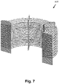
- a typical prior art heat exchange array 600 is shown in Figure 6 .
- the heat exchange array comprises a plurality of helically coiled tubes, the first of which is labelled 602. Each of the coils runs from an input header 604 to an output header 606. All of the coils of the heat exchange array 600 have the same chirality, and so are attached to each of the input header and output header from the same direction. The stress forces within the coils will therefore combine such that they may cause a distortion in the shape of the heat exchange array 600.
- FIG. 7 A cross sectional view of the prior art heat exchange array 600 is shown in Figure 7 . This view shows how helical coils of the same chirality are also difficult to pack efficiently, and cannot be easily distributed uniformly throughout the heat exchange array.
- FIG. 1 shows a heat exchange array 100 according to an embodiment of the present invention.
- the heat exchange array 100 comprises first heat exchange tubes 102 and second heat exchange tubes 104.
- Each of the heat exchange tubes is arranged to carry a heat exchange medium.
- the heat exchange medium may be water, or any other suitable fluid such as steam, oil, gas.
- the first heat exchange tubes 102 each comprise a left-handed helically coiled tube.
- the second heat exchange tubes 104 each comprise a right-handed helically coiled tube.
- a left-handed helix is defined as a helix where when viewed along the helix's axis, a clockwise screwing motion moves the helix towards the observer.
- a right-handed helix is defined as a helix where when viewed along the helix's axis, a clockwise screwing motion moves the helix away the observer.
- the first 102 and second 104 heat exchange tubes are manufactured by winding a straight length of tubing into a helical coil. As the tubing is wound an elastic stress is generated within each tube that acts to return the tube to its original shape. The elastic stress generated within the first heat exchange tubes 102 will act in an opposite direction to that found in the second heat exchange coils 104 due to the tubes being wound into left-handed and right-handed helixes.
- the first 102 and second 104 heat exchange tubes are interconnected such that the elastic stress in the first heat exchange tubes 102 opposes the elastic stress in the second heat exchange tubes 104. The elastic stresses are therefore balanced and at least partly cancel out, thus reducing the overall stress within the heat exchange array 100.
- the first heat exchange coils 102 and the second heat exchange coils 104 are arranged coaxially such that the heat exchange array 100 is made up of layers of concentric helical coils.
- Each layer of the heat exchange array 100 is made up of first heat exchange tubes 102 (having a left-handed helix) or second heat exchange tubes 104 (each having a right-handed helix).
- Each layer of heat exchange tubes surrounds the layer before - i.e. the radius of curvature of the helical coils of each layer increases further from the central axis).
- the composition of each layer alternates between being made up only of first heat exchange tubes 102 and only of second heat exchange tubes 104.
- the inner most layer comprises a pair of left-handed helical coils 102a, 102b.
- the next layer comprises a pair of right-handed helical coils 104a, 104b.
- the third layer comprises a pair of left-handed coils 102c, 102d and so on until the seventh layer, which comprises a pair of left-handed coils 102g, 102h.
- first heat exchange tubes 102 there are four layers of first heat exchange tubes 102 and three layers of second heat exchange tubes 104. In other embodiments, there may be an equal number of layers of first heat exchange tubes 102 and second heat exchange tubes 104.
- each layer may comprise only one first 102 or second 104 heat exchange tube. In other embodiments, each layer may comprise any other suitable number of first 102 or second 104 heat exchange tubes depending on the size requirement of the heat exchange array. For example, each layer may comprise 3, 4, 5, 6 or more first or second heat exchange tubes.
- the first 102 and second heat 104 exchange tubes are interconnected via support members 106, which in this embodiment are rigid, arranged to hold the helically coiled tubes 102, 104 in a fixed shape.
- support members 106 which in this embodiment are rigid, arranged to hold the helically coiled tubes 102, 104 in a fixed shape.
- support members 106a, 106b, 106c, 106d, 106e, 106f there may be any other suitable number of support members.
- the support members 106 each comprise a support bracket defining apertures arranged to receive each turn of the helically coiled tubes 102,104.
- the support members 106 are arranged to keep the heat exchange tubes 102, 104 in their coiled up shape.
- the support members 106 have a width sufficient to support a plurality of fins.
- the heat exchange tubes are mechanically locked to the support members to secure them in position perhaps via a tang dependent from the support members 106.
- the heat exchange tubes may have a tight friction fit with the apertures of the support member to secure them in place.
- the support members may comprise two parts, each having a series of indentations arranged to receive the turns of the coils as they are wound. When the two parts are attached together the indentations are closed off to form apertures to fix the coils in place.
- each indentation may comprise a complementarily shaped recess arranged to receive a portion of a heat exchange tube.
- the heat exchange array 100 further comprises an input header 108 and an output header 110.
- the headers 108, 110 are arranged to provide an input or output for a heat exchange medium into the tubes.
- the input header 108 is connected to a first end of each of the first 102 and second 104 heat exchange tubes.
- the output header 110 is connected to a second end of each of the first 102 and second 104 heat exchange tubes.
- the heat exchange medium can therefore flow into one end of the tubes via the input header, through the tubes such that heat exchange can occur, and then exit the tubes via the output header.
- each of the first heat exchange tubes 102 are connected to the output header 110 from an opposite direction (ie from either side of a vertical, as viewed in the figure, axis through the header) to each of the second heat exchange tubes 104.
- each of the second heat exchange tubes 104 are connected to the input header 108 from an opposite direction (ie from either side of a vertical, as viewed in the figure, axis through the header) to each of the first heat exchange tubes 102.
- This improves access to the heat exchange tubes and allows them to be more easily welded, or otherwise attached, onto the input 108 and output 110 headers. Attaching the heat exchange tubes from opposite directions may also allow the elastic stresses within the first heat exchange tubes 102 acting on the headers 108, 110 to oppose the elastic stresses within the second heat exchange tubes 104.
- Each of the first heat exchange tubes 102 has substantially the same length as each of the second heat exchange tubes 104. This means that the heat exchange medium travels the same distance in each of the heat exchange tubes, and therefore spends an equal amount of time in each of the heat exchange tubes if the heat exchange medium travels at the same speed. As a result the energy imparted to the heat exchange medium is substantially the same for each of the heat exchange tubes.
- the first heat exchange tube 102 comprise a left-handed helically coiled tube having a pitch that is different to that of the second heat exchange tube 104.
- the pitch of the helical coils increases in each consecutive layer moving outward from the central axis.
- the increasing helical radius of curvature in coils further from the central axis is therefore counter balanced by a change in pitch reducing the number of turns required in the coil.
- either one, or both, of the first 102 and second 104 heat exchange tubes comprise external fins or other similar protrusions.
- both heat exchange tubs comprise external fins. These increase the surface area of heat exchange tubes in order to improve the heat exchange efficiency.
- the fins or protrusions may also engage with the support member (i.e. are disposed on either side of the support member at the position where it is connect to the heat exchange tube) to help keep the tube fixed relative to the support member.
- Figures 8a and 8b show schematics of segments 800a, 800b of tubes 102 and/or 104 in an embodiment wherein one or both of the tubes comprise external fins 802a, 802b.
- the external fins 802a, 802b are spiral fins.
- the turns of the external fins 802a, 802b are equispaced along the length of the tube.
- the individual turns of the spiral fin are referred to as external fins below for simplicity.
- equi-spacing of the external fins is not a necessary feature, but may be preferable for even heat distribution in some embodiments.
- the external fins 802a, 802b are substantially parallel to each other and substantially perpendicular to the tube surface.
- the skilled person will understand that, as the tubes 102, 104 are coiled, the tube surfaces bend. The angle between the tube surface and the external fins 802a, 802b may change as the tubes are coiled such that adjacent external fins may no longer be parallel to each other and may even touch within the inner circumference of the coiled tube 102, 104.
- the support members 106 are sufficiently wide (ie have a sufficient width) to support more than one external fin 802a, 802b on each turn of the helically coiled tubes 102,104 received.
- the first 102 and second 104 heat exchange tubes are circular in cross section, and have a diameter of between approximately 21.3 mm and 168.3 mm.
- the radius of curvature of the left-handed helically coiled tube and right-handed helically coiled tube is between roughly 1m and 4m.
- the external fins 802a, 802b of the first 102 and second 104 heat exchange tubes have heights of between approximately 10 mm and 240 mm, and more preferably between 20 mm and 50 mm.
- the heat exchange array 100 may be assembled into a heat exchange unit by enclosing the heat exchange tubes in a duct through which exhaust gas is passed.
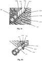
- FIGs 3 and 4 show a method of producing the heat exchange array 100 using a rotating mandrel 200.
- the mandrel 200 comprises a drive means 202 which is arranged to rotate a roller portion 204.
- the rotating portion is substantially cylindrical in shape and is rotated by an axle 205 about central axis XX shown in Figure 3 and 4 .
- the line XX lies substantially along an axial direction of the array that is formed by the method.
- the axle 205 is driven at one end by the drive means 202 and supported at the other by a supporting means 206.
- Coil support frame 208 is provided at the ends of the rolling portion 204 to keep the heat exchange tubes in place.
- the method of producing the heat exchange coil comprises the following steps:
- shims are periodically placed upon the inner heat exchange tube is a outer heat exchange tube is wound therearound.
- the shim is placed at intermediate positions between the support members and helps to ensure that the tubes bend between the support members, and take a curved shape, as the mandrel 200 is rotated.
- the shims may or may not be removed from the after the heat exchange array has been fabricated.
- first heat exchange tube 102 is wound into a helical coil within an opposite chirality to that of the second heat exchange tube 104 (i.e. one forms a left-handed helix and the other a right-handed helix).
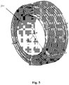
- Steps (a) to (f) above may be repeated to build up a heat exchange array comprising a plurality of the first 102 and/or the second 104 heat exchange coils in a plurality of concentric layers as shown in Figure 5 .
- each of the support member has a length along the circumferential length of a coil such that the or each support member supports a plurality of fins.
- Figure 5 also has labelled for ease of reference two axes: the axial direction 500 of the coils and the array; and the radial direction 502 of the coils and the array.
- the support members and the shims it is convenient to think of the height thereof as being in the radial direction 502 and the width being substantially in the circumferential direction of a coil supported by the shim / support member.
- step (b) a plurality of first heat exchange tubes 102 may be held to the first support member 212 so that each concentric layer comprises a plurality of first heat exchange coils 102.
- step (e) a plurality of second heat exchange tubes 104 may be held to the second support member 213 so that each concentric layer comprises a plurality of first heat exchange coils 104.
- a pulling force away from the roller portion 204 is applied to the heat exchange tubes 102, 104.
- the pulling force helps to ensure that the heat exchange tubes 102, 104 are coiled tightly. If the heat exchange tubes 102, 104 are coiled too loosely, the coil may spring away from the support members 212 and not retain the desired shape.
- the spacing between the indentations of the support members may be adjusted. By increasing the spacing of the indentations along the length of the rotating portion 204, the pitch of the helical coil wound onto it will be increased.
- first direction Y and the second direction Z could be the same i.e. the first and second heat exchange tubes are wound onto the roller portion 204 from the same end.
- direction of rotation of the roller portion 204 can be reversed between each layer to produce helical coils with opposite chirality.
Landscapes
- Engineering & Computer Science (AREA)
- Mechanical Engineering (AREA)
- Physics & Mathematics (AREA)
- Thermal Sciences (AREA)
- General Engineering & Computer Science (AREA)
- Heat-Exchange Devices With Radiators And Conduit Assemblies (AREA)
Claims (15)
- Wärmeaustauschanordnung (100) zur Verwendung in einer Wärmeaustauscheinheit zur Rückgewinnung von Energie aus einem Abgas aus einem Kraftwerk, wobei die Anordnung (100) Folgendes umfasst:ein erstes Wärmeaustauschrohr (102) und ein zweites Wärmeaustauschrohr (104), die jeweils dazu angeordnet sind, ein Wärmeaustauschmedium zu führen, und ferner jeweils eine Reihe von äußeren Rippen (802) umfassen; undwobei das erste Wärmeaustauschrohr ein linksgängiges spiralförmig gewundenes Rohr (102) mit einer ersten elastischen Spannung umfasst und die zweite Wärmeaustauschwindung ein rechtsgängiges spiralförmig gewundenes Rohr (104) mit einer zweiten elastischen Spannung umfasst,und wobei die ersten (102) und zweiten (104) Wärmeaustauschrohre durch mindestens ein starres Stützelement (106; 212, 213), das dazu angeordnet ist, die spiralförmig gewundenen Rohre (102, 104) in einer festen Form zu halten, derart miteinander verbunden und mechanisch arretiert sind, dass die erste elastische Spannung der zweiten elastischen Spannung entgegenwirkt, und wobei das oder jedes Stützelement (106) eine derartige Länge entlang des Umfangs der Windung aufweist, dass das oder jedes Stützelement (106) eine Mehrzahl der äußeren Rippen (802) stützt.
- Wärmeaustauschanordnung (100) nach Anspruch 1, wobei das Stützelement (106) mindestens eine Stützhalterung umfasst, die Öffnungen definiert, die dazu angeordnet sind, jede Wicklung der spiralförmig gewundenen Rohre (102' 104) aufzunehmen.
- Wärmeaustauschanordnung (100) nach einem der vorhergehenden Ansprüche, ferner umfassend ein Sammelrohr (108, 110), das mit einem Endbereich der ersten und einem Endbereich der zweiten Wärmeaustauschrohre verbunden ist, wobei das Sammelrohr (108, 110) dazu angeordnet ist, einen Eingang oder Ausgang für ein Wärmeaustauschmedium in die Rohre (102, 104) bereitzustellen, und vorzugsweise wobei die ersten und zweiten Wärmeaustauschrohre (102, 104) mit dem Sammelrohr (108, 110) aus entgegengesetzten Richtungen verbunden sind.
- Wärmeaustauschanordnung (100) nach einem der vorhergehenden Ansprüche, wobei das erste Wärmeaustauschrohr (102) im Wesentlichen dieselbe Länge wie das zweite Wärmeaustauschrohr (104) aufweist.
- Wärmeaustauschanordnung (100) nach einem der vorhergehenden Ansprüche, wobei das erste Wärmeaustauschrohr (102) ein linksgängiges spiralförmig gewundenes Rohr mit einer ersten Teilung umfasst und das zweite Wärmeaustauschrohr (104) ein rechtsgängiges spiralförmig gewundenes Rohr mit einer zweiten Teilung umfasst, wobei die erste Teilung nicht gleich der zweiten Teilung ist.
- Wärmeaustauschanordnung (100) nach einem der vorhergehenden Ansprüche, wobei das erste Wärmeaustauschrohr (102) und das zweite Wärmeaustauschrohr (104) koaxial angeordnet sind.
- Wärmeaustauschanordnung (100) nach einem der vorhergehenden Ansprüche, wobei das erste Wärmeaustauschrohr (102) das zweite Wärmeaustauschrohr (104) umgibt oder umgekehrt, und vorzugsweise ferner umfassend eine Mehrzahl von ersten und/oder zweiten Wärmeaustauschrohren (102, 104), die in einer Mehrzahl von konzentrischen Schichten angeordnet sind, und optional wobei jede der konzentrischen Schichten eine Mehrzahl von linksgängigen spiralförmig gewundenen Rohren, die jeweils denselben Krümmungsradius aufweisen, oder eine Mehrzahl von rechtsgängigen spiralförmig gewundenen Rohren, die jeweils denselben Krümmungsradius aufweisen, umfasst.
- Wärmeaustauschanordnung (100) nach Anspruch 7, wobei die konzentrischen Schichten abwechselnd erste Wärmeaustauschrohre (102) umfassen und zweite Wärmeaustauschrohre (104) umfassen und vorzugsweise eine gleiche Anzahl von ersten und zweiten Wärmeaustauschrohren (102, 104) umfassen.
- Wärmeaustauschanordnung (100) nach einem der vorhergehenden Ansprüche, wobei die ersten und zweiten Wärmeaustauschrohre (102, 104) im Querschnitt kreisförmig sind und einen Durchmesser von etwa zwischen 21 mm und 168 mm aufweisen oder wobei der Krümmungsradius des linksgängigen spiralförmig gewundenen Rohrs und des rechtsgängigen spiralförmig gewundenen Rohrs zwischen 1 m und 4 m beträgt.
- Wärmeaustauscheinheit, umfassend die Wärmeaustauschanordnung (100) nach einem der vorhergehenden Ansprüche.
- Verfahren zum Herstellen einer Wärmeaustauschanordnung (100) nach Anspruch 1, wobei die Anordnung (100) eine Mehrzahl von Wärmeaustauschrohren (102, 104) umfasst, die jeweils eine Mehrzahl von äußeren Rippen (802) aufweisen, wobei das Verfahren Verwenden eines drehbaren Dorns (200) und die folgenden Schritt umfasst:(a) Bereitstellen mindestens eines ersten starren Stützelements (106) an einem Walzenabschnitt (204) des Dorns zum Aufnehmen eines ersten Wärmeaustauschrohrs;(b) Halten eines Endes des Wärmeaustauschrohrs (102) an dem ersten Stützelement (212);(c) Drehen der Walze (204) während eines Vorschiebens des ersten Wärmeaustauschrohrs (102) entlang einer Länge der Walze (204) in einer ersten Richtung zum Formen des ersten Wärmeaustauschrohrs (102) in eine erste spiralförmige Windung;(d) Anbringen eines zweiten starren Stützelements (213), das zum Aufnehmen eines zweiten Wärmeaustauschrohrs (104) angeordnet ist, an dem ersten Stützelement (212);(e) Halten eines Endes des zweiten Wärmeaustauschrohrs (104) an dem zweiten Stützelement (213); und(f) Drehen der Walze (204) in derselben Richtung während eines Vorschiebens des zweiten Wärmeaustauschrohrs (104) entlang einer Länge der Walze (204) in einer zweiten Richtung zum Formen des zweiten Wärmeaustauschrohrs (104) in eine zweite spiralförmige Windung, wobei die erste Richtung entgegengesetzt zu der zweiten Richtung ist, so dass die erste spiralförmige Windung (102) eine entgegengesetzte Gängigkeit zu der zweiten spiralförmigen Windung (104) aufweist, und wobei die ersten und zweiten Stützelemente (212, 213) die spiralförmig gewundenen Rohre (102, 104) in einer festen Form halten, so dass die erste elastische Spannung der zweiten elastischen Spannung entgegenwirkt, und wobei das oder jedes Stützelement (212, 213) eine derartige Länge entlang des Umfangs der Windung aufweist, dass das oder jedes Stützelement (212, 213) eine Mehrzahl von Rippen stützt.
- Verfahren zum Herstellen einer Wärmeaustauschanordnung (100) nach Anspruch 11, wobei das Verfahren ferner Wiederholen der Schritte (a) bis (f) umfasst, um eine Wärmeaustauschanordnung (100) bereitzustellen, die eine Mehrzahl der ersten und/oder der zweiten Wärmeaustauschwindungen (102, 104) in einer Mehrzahl von konzentrischen Schichten umfasst.
- Verfahren zum Herstellen einer Wärmeaustauschanordnung (100) nach Anspruch 11 oder Anspruch 12, wobei Schritt (b) Halten einer Mehrzahl von ersten Wärmeaustauschrohren (102) an dem ersten Stützelement (212) derart umfasst, dass jede konzentrische Schicht eine Mehrzahl von ersten Wärmeaustauschwindungen umfasst.
- Verfahren zum Herstellen einer Wärmeaustauschanordnung (100) nach einem der Ansprüche 11 bis 13, wobei Schritt (e) Halten einer Mehrzahl von zweiten Wärmeaustauschrohren (104) an dem zweiten Stützelement (213) derart umfasst, dass jede konzentrische Schicht eine Mehrzahl von zweiten Wärmeaustauschwindungen umfasst.
- Verfahren zum Herstellen einer Wärmeaustauschanordnung nach einem der Ansprüche 11 bis 14, wobei Abstandselemente an Zwischenpositionen zwischen Stützelementen (212, 213) platziert werden, während die Rohre (102, 104) aufgewunden werden.
Applications Claiming Priority (2)
| Application Number | Priority Date | Filing Date | Title |
|---|---|---|---|
| GBGB1319284.4A GB201319284D0 (en) | 2013-10-31 | 2013-10-31 | Heat exchange array |
| PCT/GB2014/053247 WO2015063503A1 (en) | 2013-10-31 | 2014-10-31 | Heat exchange array |
Publications (2)
| Publication Number | Publication Date |
|---|---|
| EP3063489A1 EP3063489A1 (de) | 2016-09-07 |
| EP3063489B1 true EP3063489B1 (de) | 2022-07-13 |
Family
ID=49767496
Family Applications (1)
| Application Number | Title | Priority Date | Filing Date |
|---|---|---|---|
| EP14805324.2A Active EP3063489B1 (de) | 2013-10-31 | 2014-10-31 | Wärmeaustauschanordnung |
Country Status (8)
| Country | Link |
|---|---|
| US (2) | US20180195807A1 (de) |
| EP (1) | EP3063489B1 (de) |
| AU (1) | AU2014343444B2 (de) |
| ES (1) | ES2928329T3 (de) |
| GB (1) | GB201319284D0 (de) |
| MX (1) | MX2016005419A (de) |
| MY (1) | MY181816A (de) |
| WO (1) | WO2015063503A1 (de) |
Families Citing this family (11)
| Publication number | Priority date | Publication date | Assignee | Title |
|---|---|---|---|---|
| WO2020007503A1 (de) * | 2018-07-04 | 2020-01-09 | Linde Aktiengesellschaft | Rohrbündelstabilisierung für gewickelte wärmeübertrager |
| US11841194B2 (en) | 2018-07-04 | 2023-12-12 | Linde Gmbh | Directed decoupling between bundle and core tube in wound heat exchangers |
| WO2020025167A1 (de) * | 2018-07-28 | 2020-02-06 | Linde Aktiengesellschaft | Abstützung von rohren gewickelter wärmeübertrager |
| CN108662940A (zh) * | 2018-08-29 | 2018-10-16 | 浙江格洛维能源科技有限公司 | 一种新型盘管固定支撑装置 |
| USD894357S1 (en) * | 2019-01-22 | 2020-08-25 | Nathaniel S. Roady | Refrigerant coil segment |
| WO2020253992A1 (de) * | 2019-06-21 | 2020-12-24 | Linde Gmbh | Thermische vorspannung für die bündelrohre eines gewickelten wärmeübertragers |
| RS20200036A1 (sr) * | 2020-01-13 | 2021-07-30 | Stamenic Aleksandar | Uređaj za razmenu energije između medijuma sa poboljšanom strukturom i performansama |
| CN114061150B (zh) * | 2020-07-29 | 2023-04-07 | 芜湖美的厨卫电器制造有限公司 | 热交换器和热水装置 |
| CN115127381A (zh) * | 2022-05-30 | 2022-09-30 | 广州英诺节能设备有限公司 | 一种换热盘管及制造方法 |
| FI20225776A1 (en) * | 2022-09-05 | 2024-03-06 | Uponor Infra Oy | Heat exchanger and method for its manufacture |
| CN115228995B (zh) * | 2022-09-26 | 2022-12-13 | 东方法马通核泵有限责任公司 | 一种冷却双盘管的绕制装置及绕制方法 |
Family Cites Families (8)
| Publication number | Priority date | Publication date | Assignee | Title |
|---|---|---|---|---|
| US3083447A (en) * | 1957-11-07 | 1963-04-02 | Union Carbide Corp | Method of assembling a bundle of coils in a heat exchange device |
| DE1452409B2 (de) * | 1963-07-20 | 1971-02-04 | Roffelsen, Franciscus, Heimond (Niederlande) | Dreh und Vorschubantrieb an einer Vorrichtung zum schraubenförmigen Aufwickeln von bandförmigen Warmeaustauschkorpern auf Metallrohre |
| GB1163804A (en) * | 1967-06-16 | 1969-09-10 | Richmond Engineering Company I | Water Heating Apparatus |
| MY110237A (en) * | 1987-05-25 | 1998-03-31 | Dunham Bush International Cayman Ltd | Improved method of manufacturing heat exchangers |
| TW445366B (en) * | 1998-05-15 | 2001-07-11 | Noboru Maruyama | Assembly body of heat exchange coils |
| JP2002147976A (ja) * | 2000-11-13 | 2002-05-22 | M Technique Co Ltd | 熱交換器 |
| GB2463482B (en) * | 2008-09-12 | 2012-05-02 | Tanjung Citech Uk Ltd | A heat exchange unit |
| IT1396671B1 (it) * | 2009-04-27 | 2012-12-14 | Mta Spa | Scambiatore a microcanali |
-
2013
- 2013-10-31 GB GBGB1319284.4A patent/GB201319284D0/en not_active Ceased
-
2014
- 2014-10-31 ES ES14805324T patent/ES2928329T3/es active Active
- 2014-10-31 AU AU2014343444A patent/AU2014343444B2/en not_active Ceased
- 2014-10-31 WO PCT/GB2014/053247 patent/WO2015063503A1/en not_active Ceased
- 2014-10-31 MY MYPI2016701527A patent/MY181816A/en unknown
- 2014-10-31 MX MX2016005419A patent/MX2016005419A/es unknown
- 2014-10-31 EP EP14805324.2A patent/EP3063489B1/de active Active
- 2014-10-31 US US15/033,361 patent/US20180195807A1/en not_active Abandoned
-
2022
- 2022-01-26 US US17/584,980 patent/US11802737B2/en active Active
Also Published As
| Publication number | Publication date |
|---|---|
| US11802737B2 (en) | 2023-10-31 |
| EP3063489A1 (de) | 2016-09-07 |
| US20180195807A1 (en) | 2018-07-12 |
| US20220325958A1 (en) | 2022-10-13 |
| WO2015063503A1 (en) | 2015-05-07 |
| GB201319284D0 (en) | 2013-12-18 |
| ES2928329T3 (es) | 2022-11-17 |
| AU2014343444B2 (en) | 2018-01-25 |
| MY181816A (en) | 2021-01-08 |
| MX2016005419A (es) | 2016-08-19 |
Similar Documents
| Publication | Publication Date | Title |
|---|---|---|
| US11802737B2 (en) | Helically coiled heat exchange array | |
| AU2014343444A1 (en) | Heat exchange array | |
| US5690167A (en) | Inner ribbed tube of hard metal and method | |
| US9109844B2 (en) | Nested helical fin tube coil and associated manufacturing methods | |
| EP3367038B1 (de) | Wärmetauscher mit installationsflexibilität | |
| US20120312514A1 (en) | Dense twisted bundle heat exchanger | |
| CN103363820A (zh) | 传热管及使用该传热管的热交换器 | |
| CN107228581B (zh) | 单股流异径管绕管式换热器 | |
| US20130299132A1 (en) | Heat exchanger assembly and method of manufacturing therefor | |
| CN110455097A (zh) | 多股流螺旋缠绕管式高效换热器 | |
| CN105939797A (zh) | 热交换器的制造方法以及扩径治具 | |
| CN102089602B (zh) | 蒸发器 | |
| DE60207689D1 (de) | Wärmetauscher mit gewickelten Rohrschlangen | |
| CN103629968B (zh) | 一种层叠一体式内外翅片换热管及其制造方法 | |
| US4607424A (en) | Thermal regenerator | |
| CN215638937U (zh) | 一种多流程蚊香盘状螺旋管式换热器 | |
| CN210718752U (zh) | 变螺距绕管式换热器 | |
| EP4090901B1 (de) | Energieaustasuchapparat zwischen medien mit verbesserter struktur und leistung | |
| CN113566637A (zh) | 一种新型翅片盘管 | |
| CN115127381A (zh) | 一种换热盘管及制造方法 | |
| CN216245699U (zh) | 一种盘状换热器 | |
| CN210441698U (zh) | 带有套管组装防振支撑的绕管式换热器 | |
| EP2361721B1 (de) | Verfahren und Vorrichtung zur Montage von Schlangen für Wärmetauscher | |
| CN206281397U (zh) | 一种大型绕管式换热器芯体与壳体支撑结构 | |
| CN108981423B (zh) | 一种缠绕管式换热组件 |
Legal Events
| Date | Code | Title | Description |
|---|---|---|---|
| PUAI | Public reference made under article 153(3) epc to a published international application that has entered the european phase |
Free format text: ORIGINAL CODE: 0009012 |
|
| 17P | Request for examination filed |
Effective date: 20160519 |
|
| AK | Designated contracting states |
Kind code of ref document: A1 Designated state(s): AL AT BE BG CH CY CZ DE DK EE ES FI FR GB GR HR HU IE IS IT LI LT LU LV MC MK MT NL NO PL PT RO RS SE SI SK SM TR |
|
| AX | Request for extension of the european patent |
Extension state: BA ME |
|
| RIN1 | Information on inventor provided before grant (corrected) |
Inventor name: BURTON, NEIL Inventor name: WICKHAM, MARK |
|
| DAX | Request for extension of the european patent (deleted) | ||
| GRAP | Despatch of communication of intention to grant a patent |
Free format text: ORIGINAL CODE: EPIDOSNIGR1 |
|
| STAA | Information on the status of an ep patent application or granted ep patent |
Free format text: STATUS: GRANT OF PATENT IS INTENDED |
|
| INTG | Intention to grant announced |
Effective date: 20200707 |
|
| 19U | Interruption of proceedings before grant |
Effective date: 20200131 |
|
| 19W | Proceedings resumed before grant after interruption of proceedings |
Effective date: 20210201 |
|
| GRAJ | Information related to disapproval of communication of intention to grant by the applicant or resumption of examination proceedings by the epo deleted |
Free format text: ORIGINAL CODE: EPIDOSDIGR1 |
|
| GRAP | Despatch of communication of intention to grant a patent |
Free format text: ORIGINAL CODE: EPIDOSNIGR1 |
|
| 111Z | Information provided on other rights and legal means of execution |
Free format text: AL AT BE BG CH CY CZ DE DK EE ES FI FR GB GR HR HU IE IS IT LT LU LV MC MK MT NL NO PL PT RO RS SE SI SK SM TR Effective date: 20210201 |
|
| INTG | Intention to grant announced |
Effective date: 20210211 |
|
| RAP1 | Party data changed (applicant data changed or rights of an application transferred) |
Owner name: STRUTHERS ENERGY & POWER LIMITED |
|
| INTG | Intention to grant announced |
Effective date: 20210216 |
|
| GRAJ | Information related to disapproval of communication of intention to grant by the applicant or resumption of examination proceedings by the epo deleted |
Free format text: ORIGINAL CODE: EPIDOSDIGR1 |
|
| STAA | Information on the status of an ep patent application or granted ep patent |
Free format text: STATUS: REQUEST FOR EXAMINATION WAS MADE |
|
| GRAS | Grant fee paid |
Free format text: ORIGINAL CODE: EPIDOSNIGR3 |
|
| STAA | Information on the status of an ep patent application or granted ep patent |
Free format text: STATUS: GRANT OF PATENT IS INTENDED |
|
| GRAP | Despatch of communication of intention to grant a patent |
Free format text: ORIGINAL CODE: EPIDOSNIGR1 |
|
| INTC | Intention to grant announced (deleted) | ||
| INTG | Intention to grant announced |
Effective date: 20211019 |
|
| GRAA | (expected) grant |
Free format text: ORIGINAL CODE: 0009210 |
|
| STAA | Information on the status of an ep patent application or granted ep patent |
Free format text: STATUS: THE PATENT HAS BEEN GRANTED |
|
| AK | Designated contracting states |
Kind code of ref document: B1 Designated state(s): AL AT BE BG CH CY CZ DE DK EE ES FI FR GB GR HR HU IE IS IT LI LT LU LV MC MK MT NL NO PL PT RO RS SE SI SK SM TR |
|
| REG | Reference to a national code |
Ref country code: GB Ref legal event code: FG4D |
|
| REG | Reference to a national code |
Ref country code: CH Ref legal event code: EP |
|
| REG | Reference to a national code |
Ref country code: IE Ref legal event code: FG4D |
|
| REG | Reference to a national code |
Ref country code: DE Ref legal event code: R096 Ref document number: 602014084303 Country of ref document: DE |
|
| REG | Reference to a national code |
Ref country code: AT Ref legal event code: REF Ref document number: 1504483 Country of ref document: AT Kind code of ref document: T Effective date: 20220815 |
|
| REG | Reference to a national code |
Ref country code: NL Ref legal event code: FP |
|
| REG | Reference to a national code |
Ref country code: LT Ref legal event code: MG9D |
|
| REG | Reference to a national code |
Ref country code: ES Ref legal event code: FG2A Ref document number: 2928329 Country of ref document: ES Kind code of ref document: T3 Effective date: 20221117 |
|
| REG | Reference to a national code |
Ref country code: NO Ref legal event code: T2 Effective date: 20220713 |
|
| PG25 | Lapsed in a contracting state [announced via postgrant information from national office to epo] |
Ref country code: SE Free format text: LAPSE BECAUSE OF FAILURE TO SUBMIT A TRANSLATION OF THE DESCRIPTION OR TO PAY THE FEE WITHIN THE PRESCRIBED TIME-LIMIT Effective date: 20220713 Ref country code: RS Free format text: LAPSE BECAUSE OF FAILURE TO SUBMIT A TRANSLATION OF THE DESCRIPTION OR TO PAY THE FEE WITHIN THE PRESCRIBED TIME-LIMIT Effective date: 20220713 Ref country code: PT Free format text: LAPSE BECAUSE OF FAILURE TO SUBMIT A TRANSLATION OF THE DESCRIPTION OR TO PAY THE FEE WITHIN THE PRESCRIBED TIME-LIMIT Effective date: 20221114 Ref country code: LV Free format text: LAPSE BECAUSE OF FAILURE TO SUBMIT A TRANSLATION OF THE DESCRIPTION OR TO PAY THE FEE WITHIN THE PRESCRIBED TIME-LIMIT Effective date: 20220713 Ref country code: LT Free format text: LAPSE BECAUSE OF FAILURE TO SUBMIT A TRANSLATION OF THE DESCRIPTION OR TO PAY THE FEE WITHIN THE PRESCRIBED TIME-LIMIT Effective date: 20220713 Ref country code: FI Free format text: LAPSE BECAUSE OF FAILURE TO SUBMIT A TRANSLATION OF THE DESCRIPTION OR TO PAY THE FEE WITHIN THE PRESCRIBED TIME-LIMIT Effective date: 20220713 |
|
| REG | Reference to a national code |
Ref country code: AT Ref legal event code: MK05 Ref document number: 1504483 Country of ref document: AT Kind code of ref document: T Effective date: 20220713 |
|
| PG25 | Lapsed in a contracting state [announced via postgrant information from national office to epo] |
Ref country code: PL Free format text: LAPSE BECAUSE OF FAILURE TO SUBMIT A TRANSLATION OF THE DESCRIPTION OR TO PAY THE FEE WITHIN THE PRESCRIBED TIME-LIMIT Effective date: 20220713 Ref country code: IS Free format text: LAPSE BECAUSE OF FAILURE TO SUBMIT A TRANSLATION OF THE DESCRIPTION OR TO PAY THE FEE WITHIN THE PRESCRIBED TIME-LIMIT Effective date: 20221113 Ref country code: HR Free format text: LAPSE BECAUSE OF FAILURE TO SUBMIT A TRANSLATION OF THE DESCRIPTION OR TO PAY THE FEE WITHIN THE PRESCRIBED TIME-LIMIT Effective date: 20220713 Ref country code: GR Free format text: LAPSE BECAUSE OF FAILURE TO SUBMIT A TRANSLATION OF THE DESCRIPTION OR TO PAY THE FEE WITHIN THE PRESCRIBED TIME-LIMIT Effective date: 20221014 |
|
| REG | Reference to a national code |
Ref country code: DE Ref legal event code: R097 Ref document number: 602014084303 Country of ref document: DE |
|
| PG25 | Lapsed in a contracting state [announced via postgrant information from national office to epo] |
Ref country code: SM Free format text: LAPSE BECAUSE OF FAILURE TO SUBMIT A TRANSLATION OF THE DESCRIPTION OR TO PAY THE FEE WITHIN THE PRESCRIBED TIME-LIMIT Effective date: 20220713 Ref country code: RO Free format text: LAPSE BECAUSE OF FAILURE TO SUBMIT A TRANSLATION OF THE DESCRIPTION OR TO PAY THE FEE WITHIN THE PRESCRIBED TIME-LIMIT Effective date: 20220713 Ref country code: DK Free format text: LAPSE BECAUSE OF FAILURE TO SUBMIT A TRANSLATION OF THE DESCRIPTION OR TO PAY THE FEE WITHIN THE PRESCRIBED TIME-LIMIT Effective date: 20220713 Ref country code: CZ Free format text: LAPSE BECAUSE OF FAILURE TO SUBMIT A TRANSLATION OF THE DESCRIPTION OR TO PAY THE FEE WITHIN THE PRESCRIBED TIME-LIMIT Effective date: 20220713 Ref country code: AT Free format text: LAPSE BECAUSE OF FAILURE TO SUBMIT A TRANSLATION OF THE DESCRIPTION OR TO PAY THE FEE WITHIN THE PRESCRIBED TIME-LIMIT Effective date: 20220713 |
|
| PLBE | No opposition filed within time limit |
Free format text: ORIGINAL CODE: 0009261 |
|
| STAA | Information on the status of an ep patent application or granted ep patent |
Free format text: STATUS: NO OPPOSITION FILED WITHIN TIME LIMIT |
|
| PG25 | Lapsed in a contracting state [announced via postgrant information from national office to epo] |
Ref country code: SK Free format text: LAPSE BECAUSE OF FAILURE TO SUBMIT A TRANSLATION OF THE DESCRIPTION OR TO PAY THE FEE WITHIN THE PRESCRIBED TIME-LIMIT Effective date: 20220713 Ref country code: MC Free format text: LAPSE BECAUSE OF FAILURE TO SUBMIT A TRANSLATION OF THE DESCRIPTION OR TO PAY THE FEE WITHIN THE PRESCRIBED TIME-LIMIT Effective date: 20220713 Ref country code: EE Free format text: LAPSE BECAUSE OF FAILURE TO SUBMIT A TRANSLATION OF THE DESCRIPTION OR TO PAY THE FEE WITHIN THE PRESCRIBED TIME-LIMIT Effective date: 20220713 |
|
| REG | Reference to a national code |
Ref country code: CH Ref legal event code: PL |
|
| 26N | No opposition filed |
Effective date: 20230414 |
|
| PG25 | Lapsed in a contracting state [announced via postgrant information from national office to epo] |
Ref country code: LU Free format text: LAPSE BECAUSE OF NON-PAYMENT OF DUE FEES Effective date: 20221031 Ref country code: AL Free format text: LAPSE BECAUSE OF FAILURE TO SUBMIT A TRANSLATION OF THE DESCRIPTION OR TO PAY THE FEE WITHIN THE PRESCRIBED TIME-LIMIT Effective date: 20220713 |
|
| PG25 | Lapsed in a contracting state [announced via postgrant information from national office to epo] |
Ref country code: LI Free format text: LAPSE BECAUSE OF NON-PAYMENT OF DUE FEES Effective date: 20221031 Ref country code: CH Free format text: LAPSE BECAUSE OF NON-PAYMENT OF DUE FEES Effective date: 20221031 |
|
| PG25 | Lapsed in a contracting state [announced via postgrant information from national office to epo] |
Ref country code: SI Free format text: LAPSE BECAUSE OF FAILURE TO SUBMIT A TRANSLATION OF THE DESCRIPTION OR TO PAY THE FEE WITHIN THE PRESCRIBED TIME-LIMIT Effective date: 20220713 |
|
| PG25 | Lapsed in a contracting state [announced via postgrant information from national office to epo] |
Ref country code: HU Free format text: LAPSE BECAUSE OF FAILURE TO SUBMIT A TRANSLATION OF THE DESCRIPTION OR TO PAY THE FEE WITHIN THE PRESCRIBED TIME-LIMIT; INVALID AB INITIO Effective date: 20141031 |
|
| PG25 | Lapsed in a contracting state [announced via postgrant information from national office to epo] |
Ref country code: CY Free format text: LAPSE BECAUSE OF FAILURE TO SUBMIT A TRANSLATION OF THE DESCRIPTION OR TO PAY THE FEE WITHIN THE PRESCRIBED TIME-LIMIT Effective date: 20220713 |
|
| PG25 | Lapsed in a contracting state [announced via postgrant information from national office to epo] |
Ref country code: MK Free format text: LAPSE BECAUSE OF FAILURE TO SUBMIT A TRANSLATION OF THE DESCRIPTION OR TO PAY THE FEE WITHIN THE PRESCRIBED TIME-LIMIT Effective date: 20220713 |
|
| PG25 | Lapsed in a contracting state [announced via postgrant information from national office to epo] |
Ref country code: TR Free format text: LAPSE BECAUSE OF FAILURE TO SUBMIT A TRANSLATION OF THE DESCRIPTION OR TO PAY THE FEE WITHIN THE PRESCRIBED TIME-LIMIT Effective date: 20220713 |
|
| PG25 | Lapsed in a contracting state [announced via postgrant information from national office to epo] |
Ref country code: BG Free format text: LAPSE BECAUSE OF FAILURE TO SUBMIT A TRANSLATION OF THE DESCRIPTION OR TO PAY THE FEE WITHIN THE PRESCRIBED TIME-LIMIT Effective date: 20220713 |
|
| PG25 | Lapsed in a contracting state [announced via postgrant information from national office to epo] |
Ref country code: MT Free format text: LAPSE BECAUSE OF FAILURE TO SUBMIT A TRANSLATION OF THE DESCRIPTION OR TO PAY THE FEE WITHIN THE PRESCRIBED TIME-LIMIT Effective date: 20220713 |
|
| PGFP | Annual fee paid to national office [announced via postgrant information from national office to epo] |
Ref country code: NO Payment date: 20250917 Year of fee payment: 12 |
|
| PGFP | Annual fee paid to national office [announced via postgrant information from national office to epo] |
Ref country code: GB Payment date: 20250916 Year of fee payment: 12 |
|
| PGFP | Annual fee paid to national office [announced via postgrant information from national office to epo] |
Ref country code: IE Payment date: 20250917 Year of fee payment: 12 |
|
| PGFP | Annual fee paid to national office [announced via postgrant information from national office to epo] |
Ref country code: NL Payment date: 20251024 Year of fee payment: 12 |
|
| PGFP | Annual fee paid to national office [announced via postgrant information from national office to epo] |
Ref country code: DE Payment date: 20251028 Year of fee payment: 12 |
|
| PGFP | Annual fee paid to national office [announced via postgrant information from national office to epo] |
Ref country code: IT Payment date: 20251022 Year of fee payment: 12 |
|
| PGFP | Annual fee paid to national office [announced via postgrant information from national office to epo] |
Ref country code: FR Payment date: 20251027 Year of fee payment: 12 |
|
| PGFP | Annual fee paid to national office [announced via postgrant information from national office to epo] |
Ref country code: BE Payment date: 20251024 Year of fee payment: 12 |
|
| PGFP | Annual fee paid to national office [announced via postgrant information from national office to epo] |
Ref country code: ES Payment date: 20251118 Year of fee payment: 12 |