EP3063487B1 - Verfahren zur regelung eines mehrkammer-brennofens mit rotierendem feuer zum brennen von kohlenstoffblöcken - Google Patents
Verfahren zur regelung eines mehrkammer-brennofens mit rotierendem feuer zum brennen von kohlenstoffblöcken Download PDFInfo
- Publication number
- EP3063487B1 EP3063487B1 EP14825373.5A EP14825373A EP3063487B1 EP 3063487 B1 EP3063487 B1 EP 3063487B1 EP 14825373 A EP14825373 A EP 14825373A EP 3063487 B1 EP3063487 B1 EP 3063487B1
- Authority
- EP
- European Patent Office
- Prior art keywords
- heating
- pressure
- ramp
- partitions
- zone
- Prior art date
- Legal status (The legal status is an assumption and is not a legal conclusion. Google has not performed a legal analysis and makes no representation as to the accuracy of the status listed.)
- Active
Links
Images


Classifications
-
- F—MECHANICAL ENGINEERING; LIGHTING; HEATING; WEAPONS; BLASTING
- F27—FURNACES; KILNS; OVENS; RETORTS
- F27B—FURNACES, KILNS, OVENS OR RETORTS IN GENERAL; OPEN SINTERING OR LIKE APPARATUS
- F27B3/00—Hearth-type furnaces, e.g. of reverberatory type; Electric arc furnaces ; Tank furnaces
- F27B3/10—Details, accessories or equipment, e.g. dust-collectors, specially adapted for hearth-type furnaces
- F27B3/12—Working chambers or casings; Supports therefor
- F27B3/14—Arrangements of linings
-
- F—MECHANICAL ENGINEERING; LIGHTING; HEATING; WEAPONS; BLASTING
- F27—FURNACES; KILNS; OVENS; RETORTS
- F27B—FURNACES, KILNS, OVENS OR RETORTS IN GENERAL; OPEN SINTERING OR LIKE APPARATUS
- F27B13/00—Furnaces with both stationary charge and progression of heating, e.g. of ring type or of the type in which a segmental kiln moves over a stationary charge
- F27B13/06—Details, accessories or equipment specially adapted for furnaces of this type
- F27B13/14—Arrangement of controlling, monitoring, alarm or like devices
-
- F—MECHANICAL ENGINEERING; LIGHTING; HEATING; WEAPONS; BLASTING
- F27—FURNACES; KILNS; OVENS; RETORTS
- F27D—DETAILS OR ACCESSORIES OF FURNACES, KILNS, OVENS OR RETORTS, IN SO FAR AS THEY ARE OF KINDS OCCURRING IN MORE THAN ONE KIND OF FURNACE
- F27D19/00—Arrangements of controlling devices
-
- F—MECHANICAL ENGINEERING; LIGHTING; HEATING; WEAPONS; BLASTING
- F27—FURNACES; KILNS; OVENS; RETORTS
- F27D—DETAILS OR ACCESSORIES OF FURNACES, KILNS, OVENS OR RETORTS, IN SO FAR AS THEY ARE OF KINDS OCCURRING IN MORE THAN ONE KIND OF FURNACE
- F27D21/00—Arrangement of monitoring devices; Arrangement of safety devices
- F27D21/04—Arrangement of indicators or alarms
Definitions
- the present invention relates to so-called "fire (x) rotating chambers” furnaces, for firing carbonaceous blocks, more particularly anodes and carbon cathodes intended for the production by electrolysis of aluminum. More particularly, it relates to a method and a device for optimizing the control and safety of combustion in partition lines of such a chamber furnace.
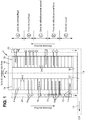
- the baking oven (FAC) 1 comprises two casings or bays 1a and 1b parallel, extending along the longitudinal axis XX along the length of the oven 1 and each having (e) a succession of transverse chambers 2 (perpendicular to the XX axis), separated from each other by transverse walls 3.
- Each chamber 2 is constituted in its length, that is to say in the transverse direction of the furnace 1, by the juxtaposition, alternately, of cells 4, open at their upper part, to enable the loading of the carbonaceous blocks to be cooked and the unloading of the cooled cooked blocks, and in which are stacked the carbonaceous blocks 5 to be embedded in a carbonaceous dust, and hollow heating partitions 6, to thin walls, generally kept spaced by transverse spacers 6a.
- the hollow partitions 6 of a chamber 2 are in the longitudinal extension (parallel to the major axis XX of the furnace 1) of the hollow partitions 6 of the other 2 chambers of the same bay 1a or 1b, and the hollow partitions 6 are in communication with each other by skylights 7 at the upper part of their longitudinal walls, facing longitudinal passages formed at this level in the transverse walls 3 , so that the hollow partitions 6 form rows of longitudinal partitions, arranged parallel to the major axis XX of the furnace and in which will circulate gaseous fluids (combustion air, fuel gas and gas and combustion fumes) to ensure preheating and baking the anodes 5, then cooling them.
- gaseous fluids combustion air, fuel gas and gas and combustion fumes
- the hollow partitions 6 further include baffles 8, to elongate and distribute more uniformly the path of the combustion gases or fumes, and these hollow partitions 6 are provided at their upper part with openings 9, called “openings", closable by removable covers and arranged in a block of crown of the oven 1.
- the two bays 1a and 1b of the oven 1 are placed in communication at their longitudinal ends by turning flues 10, which make it possible to transfer the gaseous fluids of a end of each line of hollow partitions 6 of a bay 1a or 1b at the end of the line of corresponding hollow partitions 6 on the other bay 1b or 1a, so as to form substantially rectangular loops of hollow partition lines 6 .
- fire advance (x) furnaces consists in causing a flame front to move from one chamber 2 to another which is adjacent during a cycle, each chamber 2 successively undergoing stages of preheating, forced heating, fire, then cooling (natural then forced).
- the cooking of the anodes 5 is carried out by one or more fires or groups of fires (two groups of fires being represented on the figure 1 in a position in which one extends, in this example, on thirteen chambers 2 of the span 1a and the other on thirteen chambers 2 of the span 1b) which move cyclically from chamber 2 to chamber 2.
- the blowing ramp 18 and the forced cooling ramp (s) 19 comprise combustion air insufflation pipes fed by motor fans, these pipes being connected, via the openings. 9, to the hollow partitions 6 of the rooms 2 concerned.
- the suction ramp 11 Downstream of the heating ramps 16, the suction ramp 11 is available to extract the combustion gases and fumes, generally designated by the terms “combustion fumes", which circulate in the rows of hollow partitions 6.
- the heating and cooking of the anodes 5 are ensured both by the combustion of the fuel (gaseous or liquid) injected, in a controlled manner, by the heating ramps 16, and, to a substantially equal extent, by the combustion of volatile matter (such as polycyclic aromatic hydrocarbons) pitch diffused by the anodes 5 in the cells 4 of the chambers 2 in preheating and heating zones, these volatiles, largely combustible, diffused into the cells 4 that can flow into the two adjacent hollow partitions 6 by passages formed in these partitions, to ignite in these two partitions, thanks to residual combustion air present, at this level, among the combustion fumes in these hollow partitions 6.
- volatile matter such as polycyclic aromatic hydrocarbons
- the flow of air and combustion fumes takes place along the lines of hollow partitions 6, and a negative pressure, imposed downstream of the heating zone B by the suction ramp 11 at the downstream end.
- the preheating zone A makes it possible to control the flow rate of the combustion fumes inside the hollow partitions 6, whereas the air coming from the cooling zones C and D, thanks to the cooling ramps 19 and especially to the ramp 18, is preheated in the hollow partitions 6, cooling the anodes 5 cooked in the adjacent cells 4, during its journey and serves as an oxidizer when it reaches the heating zone B.
- the whole of the ramps 11, 15, 17, 18 and the equipment and apparatus of the machine are cyclically advanced (for example every 24 hours or so) of a chamber 2. associated measurements and registration.
- the combustion fumes extracted from the fires by the suction ramps 11 are collected in a flue gas duct 20, for example a cylindrical duct partially shown on the figure 2 , with a smoke flue 21 that can have a U-shaped shape (see dotted line on the figure 1 ) or which can circumnavigate the furnace, and whose outlet 22 directs the combustion fumes sucked and collected to a smoke treatment center (CTF) not shown because not forming part of the invention.
- a flue gas duct 20 for example a cylindrical duct partially shown on the figure 2
- a smoke flue 21 that can have a U-shaped shape (see dotted line on the figure 1 ) or which can circumnavigate the furnace, and whose outlet 22 directs the combustion fumes sucked and collected to a smoke treatment center (CTF) not shown because not forming part of the invention.
- CTF smoke treatment center
- the control method of the FAC 1 essentially comprises the temperature and / or pressure regulation of the preheating zones A, heating B and natural blowing or cooling C of the oven 1 according to predefined setpoint laws.
- the regulation of the FAC 1 takes into account a multitude of parameters in order to respect the balances of the thermal transfers in the partitions. Indeed, the cooking of the carbonaceous blocks must respect in particular a curve of rise and fall in cooking temperature between the preheating zone and the working zone, so that the material undergoes the appropriate transformations and that finally the anodes obtained present the mechanical and electrical characteristics required.
- the pressure prevailing in the hollow partitions 6 must also remain, for each partition 6, substantially constant, or at least within a defined pressure range, throughout a cycle.
- the parameters to be considered are numerous, and a control regulation method of FLAC 1 must make it possible to influence one or the other of the parameters according to the measurements and to keep an optimal functioning of the FAC 1.
- the figure 3 schematically illustrates the organization of the control of a FAC 1 according to the state of the art.
- a central control unit 23 makes it possible to centralize all the data provided by the measurements, to account for the overall operation of the FAC 1.
- the injectors of the heating ramps 16 are regulated as a function of the temperature in the partitions 6 of the heating zone B. More specifically, temperature sensors in the partitions 6 of the heating zone B make it possible to regulate the temperature each of the heating ramps 16, the fuel injection being regulated in particular so that the temperature in the partitions 6 in the heating zone B follows a predetermined temperature rise curve.
- the number of heating ramps 16 is three, the ramps being referenced HR1, HR2 and HR3, the temperature of the partition associated with each ramp being respectively denoted T4, T5 and T6.
- Each heating ramp 16 is associated with a controller 24 of the PID type, which are themselves connected to the central control unit 23. The controllers 24 recover the temperature measurements T4, T5 and T6 to regulate the injectors.
- the proportion of air / fuel must approach stoichiometric proportions as much as possible, to ensure combustion both with the fuel injected by the injection ramps and with the volatile materials diffused by the firing of the carbonaceous blocks in the preheating zone A.
- the pressure prevailing in the partitions 6 of each chamber 2 of the FAC 1 must also comply with a set point. For example, it is desirable to maintain, for each partition 6, a substantially constant pressure throughout a cooking cycle, or at least to maintain the pressure within a range of values.
- the speed of the fans of the blowing ramp 18 is adjusted as a function of a pressure value Pzpr measured in a partition 6 upstream of the heating ramps 16, and in particular measured by the zero point ramp 17.
- the shutter of FIG. the suction ramp 11 is regulated according to a temperature T1 and / or a preheating pressure P1 measured in a partition 6 of the preheating zone A.
- the preheating temperature T1 in a partition 6 of the preheating zone A is in particular monitored.
- the temperature in the zone of Preheating A must allow the removal of the volatile matter contained in the pitch of the carbonaceous blocks.
- the resulting gases or vapors must then be sucked into the hollow partitions 6 and be burned immediately in the presence of oxygen in the combustion fumes arriving from the heating zone B. In fact, these gases or vapors may foul the equipment. , and in particular the suction pipes 11a and the pipes which lead to the smoke treatment center. Deposits can ignite and damage equipment.
- the preheating measurement ramp 15 then makes it possible to obtain information on the preheating temperature T1 prevailing in a partition 6 upstream of the suction ramp 11 and downstream of the heating ramps 16, in the preheating zone A, and monitor the cooking.
- the preheating temperature T1 thus measured deviates from too much of a set point, interventions must be made on the FAC 1 to bring the temperature T1 measured by the preheating measurement ramp 15 to an acceptable value.
- the preheating temperature T1 measured by the preheating measurement ramp 15 is in fact controlled while maintaining the preheating pressure P1 measured by said preheating measurement ramp 15 in a predetermined pressure range around a setpoint value.
- the preheating measurement ramp 15 and the suction ramp 11 are connected to the same controller 25 of the PID (Proportional Integral Derivative) type, itself also connected to the central control unit 23.
- the opening of the shutter of the suction ramp 11 can thus be regulated as a function of the measurement of the pressure P1 and the temperature T1 of preheating spoken controller 25.
- the preheating pressure P1 which is generally a vacuum
- the preheating measurement ramp 11 is a static measurement, so that it does not account for a change in the flow rate of flue gases flowing through partitions 6 of FAC 1.
- a problem often encountered in a FAC 1 is the clogging of the partitions 6. Indeed, when a partition 6 is clogged, even partially, the flow of fumes is hindered.
- the plugging phenomenon can have several origins, in particular the accumulation of carbonaceous dust originating from the firing of the carbonaceous blocks in the cells 4 and passing through the walls of the partitions, the debris coming clogged the partitions 6 or the deformation of the partitions 6 disturbing the flow of fumes.
- Clogging can have several undesirable effects.
- the cooking temperature curve is no longer respected. Above all, the heating ramps 16 continuing to inject fuel into the partitions 6 and the blowing ramp 18 continuing to blow combustion air, the accumulation of volatile fuel material upstream of the plug can reach a dangerous level, and to the extreme produce an explosion in the oven.
- the phenomenon of clogging is therefore even more dangerous when it occurs downstream of the heating ramp 16, after the fuel injection. It is therefore important to monitor the clogging phenomenon downstream of the heating ramp 16.
- the preheating pressure P1 does not vary.
- a malfunction of the FAC 1 may not be visible by the measurement of the preheating pressure P1.
- the regulation of the preheating temperature T1 is distorted.
- suction flow rate Q0 is generally only used as an index. Indeed, there are parasitic phenomena that can occur in FAC 1, which distorts flow measurements. The suction flow rate Q0 is therefore not a reliable indicator.
- the walls of the partitions 6 are porous, so that in the preheating zone A in particular, where the static vacuum is normally the most important, air coming from outside can infiltrate through the walls of the walls. partitions 6. The amount of air infiltrated through the porous walls is all the more important as static depression is important.
- parasitic phenomena can mask a drop in flue gas flow due to clogging, and prevent the implementation of the necessary operations to remedy it.
- a problem underlying the invention is therefore the determination of the origin of the air circulating in the partitions 6, at the base of the pressure, temperature and flow measurements, in order to regulate the operation of the FAC 1.
- a control method of a chamber furnace said "fire (x) turning (s)" for cooking carbon blocks.
- the furnace comprises a succession of chambers extending in a preheating zone, a heating zone and a natural cooling zone, the chambers being arranged in series along the longitudinal axis of the furnace.
- Each chamber is constituted by the juxtaposition, transversely to said longitudinal axis and alternately, cells in which are arranged carbon blocks to cook and hollow heating partitions, the partitions of a chamber being in communication and aligned with the partitions of the other chambers, parallel to the longitudinal axis of the furnace, in partition lines in which cooling and oxidizing air circulates and combustion gases.
- a suction ramp is connected to each of the partitions of the first chamber of the preheating zone by one respectively suction pipes.
- the necessary combustion air is partly injected by a discharge ramp of the natural cooling zone, connected to at least one fan, and partly infiltrated by depression through the partition lines.
- the fuel required for cooking the carbonaceous blocks is in turn partially injected by at least one heating ramp each extending over one respectively of at least two adjacent chambers of the heating zone, and capable of injecting in each of the partitions of the corresponding respective chamber of the heating zone.
- the oven further comprises at least one temperature sensor for measuring a preheat temperature in the partition of a chamber of the preheating zone, between the suction ramp and the heating ramp and comprises a flow meter for measuring a flow rate of suction of the air and fumes passing in at least one suction pipe.
- the oven further comprises means for determining, directly or indirectly, the heating pressure, in the heating zone, the preheating temperature is regulated to meet a set point while maintaining the suction flow in a predetermined range around a set value and while keeping the heating pressure below a minimum value.
- the oven further comprises at least one temperature sensor for measuring the suction temperature of the air in at least one a suction pipe, and wherein the suction flow rate measured in the same suction pipe is a flow rate normalized by the suction temperature.
- the means for directly determining the pressure in a partition of the heating zone comprise for example a heating pressure sensor placed on the at least one heating ramp for measuring the pressure in a partition of the heating zone.
- the means for indirectly determining the pressure in a partition of the heating zone comprise a pressure sensor for measuring the pressure in the partition of the chamber immediately downstream from the heating zone and a pressure sensor for measuring the pressure in the heating zone. the partition of the chamber immediately upstream of the heating zone.
- the flowmeter for measuring the suction flow rate measures the flow of air and fumes passing through a sill in the suction pipe in question.
- a furnace with rooms called “fire (s) turning (s)" for cooking carbon blocks.
- the oven is the one presented above, and is particularly suitable for the process presented above is implemented.
- the furnace comprises means for directly determining the heating pressure in the heating zone comprising at least one heating pressure sensor placed on the at least one heating ramp for measuring the pressure in a partition of the heating zone.
- the preheating temperature sensor can then be connected to the suction ramp, so that the oven does not have ramps dedicated exclusively to measurements.
- the claimed detection method is carried out on a furnace 1 as presented on the figures 1 and 2 , and described in the introduction, using a control system such as that shown schematically on the figure 4 .
- the method aims to use the measurement of the suction flow rate Q0 on the suction ramp 11 to regulate the preheating temperature T1 measured in a partition 6 of the preheating zone A: the preheating temperature T1 is regulated in a range of flow Q0.
- the measurement of the suction flow rate Q0 is more reliable than the measurement of the preheating pressure P1 on the preheating measurement ramp 15 according to the state of the art because the preheating measurement ramp 15 measures a static depression. , Thus, the preheating pressure P1 measured by the preheating measurement ramp 15 does not vary or very little, when a partition is clogged.
- Measurement of the flow rate Q0 accounts for a change in the flue gas flow in the event of clogging, provided that the origin of the measured flow is determined, and in particular to distinguish the air inlet from the flue gas flow. of combustion.
- the method according to the claims proposes to further use the determination of the value of the heating pressure, in a partition 6 of a chamber 2 of the heating zone B, to deduce the state of operation of the oven.
- the heating pressure can be determined directly or indirectly.
- the heating pressure is directly measured on at least one heating ramp 16, a pressure sensor being placed as close to an injector of the heating ramp 16 in question to measure a pressure P4.
- the pressure sensor can be inserted in the pup directly upstream of the quarl through which the injector of the heating ramp 16 injects the fuel into the partition 6.
- the determination in a direct way thus makes it possible to eliminate the zero-point measurement ramp 17.
- the suppression of the zero-point ramp 17 makes it possible to achieve substantial material savings. .
- the heating pressure can be determined indirectly, by means of a pressure measurement immediately upstream of the heating zone B and by a pressure measurement immediately downstream of the heating zone B.
- the ramp of zero point 17 provides a measurement of the vacuum Pzpr in a partition 6 of the chamber 2 immediately upstream of the heating zone B and a pressure sensor placed in a partition 6 of the chamber 2 of the preheating zone B immediately in downstream of the heating zone B provides a measure of the P3 depression.
- the value of the heating pressure can be positive, or negative. In the latter case, it is called heating depression.
- the FAC 1 is regulated in particular by taking into account the preheating temperature T1 measured by the preheating measurement ramp 15 in a partition 6 of the preheating zone A.
- the depression in the heating zone B is less than in the preheating zone A, so that the infiltration of air by the partitions 6 in the heating zone B can be considered negligible.
- the pressure in the heating zone B must be as low as possible to ensure suction and flue gas circulation. Thus, from the moment when the pressure in the heating zone is greater than a set value, there is a strong indicator of the presence of a plug in a partition 6.
- Additional indicators may be used as supplements to provide clues as to the state of the oven. These indicators can serve as a clue as to a malfunction, but do not allow to determine the origin of the dysfunction.
- the value of the temperature T0 in the suction pipe 11a can be used as indicating that the cooking is not proceeding as intended.
- a decrease in the temperature T0 may indicate that cooler air coming from the dead bulkheads reaches the suction pipe 11a.
- the temperature T0 also drops when a partition 6 is plugged and the hot air coming from the heating zone B does not completely reach the preheating zone A.
- the measured preheating temperature T1 is maintained, at a given instant of the cycle, at a predetermined value, with possibly a tolerance interval.
- the measurement of the flow rate Q0 and the determination of the pressure in the heating zone B provide nominal values.
- the preheating temperature T1 is decreased if the system maintains the same flow Q0.
- the temperature T1 in the preheating zone A decreases, due to the lack of smoke in the heating zone B.
- Increase the power of the injectors in the hope of increasing the temperature T1 is not effective , because of the plug, in addition to being dangerous, because increasing the risk of explosion, and not respecting the temperature curve in the heating zone B.
- the flow Q0 can be increased by respecting a range determined.
- the temperature T1 does not reach the target value.
- the depression P4 in the heating zone B the operator can see an increase in the heating pressure P4, indicating that the smoke does not circulate properly due to the presence of a plug. Operations can then be undertaken to remove the cap.
- the measurement of the pressure P1 by the preheating measurement ramp 15 becomes superfluous.
- the thermocouple measuring the preheating temperature T1 to the suction ramp 11 the preheating measurement ramp 15 can be suppressed.
- FAC 1 of the figure 4 includes two levels of control to regulate the different parameters of the FAC 1.
- a first level control unit 26 is connected to the suction ramp 11, and records the measurements of the flow rate Q0, the pressure P0 and the suction temperature T0 in at least one suction pipe 11a.
- each suction pipe of the suction ramp 11 is provided with means for measuring the flow, the pressure and the temperature in the pipe in question.
- the preheating measurement ramp of the state of the art is suppressed.
- a thermocouple 27, measuring the preheating temperature T1 in the partition 6 of the chamber 2 above which the suction ramp 11 extends, is connected to the suction ramp 11.
- the flow in each suction pipe 11a is controlled by means of a leaf placed in the suction pipe 11a.
- the leaf comprises a plurality of flaps, pivoting on their axes, and exerting control over the suction flow Q0.
- the suction flow rate Q0 in each suction pipe 11a is then preferably measured directly at the level of the sill so that it is ensured that the flow rate Q0 measured is that actually passing through the adjustable shutter. Since the pressure drops of the sill are known, the suction flow rate Q0 is measured with an increased accuracy compared to a measurement elsewhere in the suction pipe 11a: In addition, the space requirement in the suction pipe 11a is 'is diminished.
- each of the three heating ramps 6 comprises two injectors per partition 6 and a pressure sensor, placed upstream of the injector the most upstream of the heating ramp 16. It is thus obtained three pressure measurements P4, P5 and P6 heating, each associated with a heating ramp 16 to determine the value of the heating pressure. Measurement by the sensors can be synchronized with the injection so as not to damage the sensors if necessary. The heating pressure considered can then be the average of the three measurements P4, P5 and P6 or only one of the measurements, for example the one deviating the most from the reference value, can be taken into account.
- the first level control unit 26 is furthermore connected to the means for determining the depression in the heating zone B. According to the illustrated example, the first level control unit 26 is connected to associated pressure sensors. each injector, so as to collect the measurements of the depressions P4, P5 and P6 in the partitions 6 of the heating zone B. The first level control unit 26 makes it possible to analyze the measurements collected and to act on the suction ramp 11 to regulate the opening of the shutter.
- the first level control unit 26 corrects the measurement of the flow rate Q0 by the temperature T0 and the depression P0 measured in the suction pipe 11a.
- the flowmeter 12 used is calibrated to give a measurement of the flow rate Q0 under normal conditions of pressure and temperature.
- the temperature and pressure can vary greatly, and in any case do not correspond to these normal conditions. Taking into account the temperature T0 and / or the suction pressure P0, it is possible to correct the measurement of the suction flow rate Q0 and obtain reliable values.
- the first level control unit 26 is connected to a second level control unit 28, which centralizes the data of the entire oven and makes decisions on oven control.
- the second level control unit 28 is connected to a controller 24 of each injector.
- the second level control unit 28 performs the calculations based on the parameters collected, and transmits the commands to the injectors controllers 24, in order to regulate the parameters of the injectors, and in particular the order of the injections by the injectors, the time of the injectors. injection and injection power.
- the zero point ramp 17 of the state of the art is also deleted.
- the flow of ambient air blown into each of the hollow partitions 6 by the motor-fans of the blower ramp 18 is then regulated taking into account the vacuum measurements in the heating zone B, and in particular the depression P6 in the partitions 6 the most upstream of the heating zone B.
- Table 1 gives examples of numerical values for the predetermined range of authorized values for the suction flow rate Q0 and for the heating pressures P4, P5, P6 associated with the heating ramps 16, such as expected throughout a cycle. It is also indicated in Table 1, for the temperatures T4, T5, T6 measured respectively under one of the heating ramps 16 of the FAC 1, the beginning of cycle and end of cycle values corresponding to those expected in the context of a nominal operation of the FAC 1.
- Table 2 illustrates that when rear air infiltrations occur, the preheating temperature T1 does not vary, because the rear air does not reach this portion of the oven. However, the rear air reaches the suction pipe, so that the temperature T0 and the pressure P0 in the suction pipe fall. The flow Q0 in the suction pipe can be auglenté to suck the air back and continue to maintain the flow required in the oven to maintain the temperature T1 preheating.
- the preheating temperature T1 decreases.
- the temperature T0 in the suction pipe also decreases.
- the preheating temperature T1 does not return to its nominal value:
- the pressure P4 in the heating zone has however increased, out of the range of authorized values indicated. in Table 1, is thus indicating the presence of a plug.
- connection between the different equipment and the control means of the FAC 1 can be performed by means of a wired network and / or type Wi-Fj.
- the safety of the FAC 1 is enhanced, because it allows to detect more reliably than in the state of the art risk dysfunctions, including plugs in the partitions.
- the new method simplifies the furnace, by eliminating the preheating measurement ramp 11 and the zero point ramp 17 of the furnaces. the state of the art.
- the furnace 1 can advantageously be devoid of any ramp exclusively dedicated to measurements, as are the preheating measurement ramp 11 and the zero point measurement ramp 17.
Landscapes
- Engineering & Computer Science (AREA)
- Mechanical Engineering (AREA)
- General Engineering & Computer Science (AREA)
- Furnace Details (AREA)
- Baking, Grill, Roasting (AREA)
- Tunnel Furnaces (AREA)
- Waste-Gas Treatment And Other Accessory Devices For Furnaces (AREA)
- Regulation And Control Of Combustion (AREA)
- Muffle Furnaces And Rotary Kilns (AREA)
Claims (7)
- Verfahren zur Regelung eines Mehrkammer-Brennofens (1) "mit rotierendem Feuer" zum Brennen von Kohlenstoffblöcken (5), wobei der Ofen (1) eine Aufeinanderfolge von Kammern (2) umfasst, die sich in einer Vorheizzone (A), einer Heizzone (B) und einer natürlichen Kühlzone (C) erstrecken, wobei die Kammern (2) in Reihe entlang der Längsachse (XX) des Ofens (1) angeordnet sind, wobei jede Kammer (2) durch die quer zur Längsachse (XX) verlaufende und abwechselnde Aneinanderreihung von Zellen (4), in denen zu brennende Kohlenstoffblöcke (5) angeordnet sind, und Hohlwänden (6) gebildet wird, wobei die Wände (6) einer Kammer (2) mit den Wänden (6) der anderen Kammern (2) in Kommunikation stehen und parallel zur Längsachse (XX) des Ofens (1) in Wandreihen (6) ausgerichtet sind, in denen Kühl- und Verbrennungsluft und Verbrennungsgase zirkulieren, wobei eine Ansaugrampe (11) jeweils durch einen Ansaugstutzen (11a) mit jeder Wand (6) einer ersten Kammer (2) der Vorheizzone (A) verbunden ist, wobei die notwendige Verbrennungsluft zum Teil durch eine Blasrampe (18) der natürlichen Kühlzone (C), die mit mindestens einem Ventilator verbunden ist, eingespritzt wird und zum Teil durch Unterdruck über die Wandreihen (6) eindringt und wobei der zum Brennen der Kohlenstoffblöcke (5) notwendige Brennstoff zum Teil durch mindestens eine Heizrampe (16) eingespritzt wird, die sich jeweils über eine von mindestens zwei benachbarten Kammern (2) der Heizzone erstreckt und geeignet ist, Brennstoff in jede der Wände (6) der jeweiligen entsprechenden Kammer (2) der Heizzone (B) einzuspritzen, wobei der Ofen außerdem mindestens einen Temperaturfühler zur Messung einer Vorheiztemperatur (T1) in der Wand (6) einer Kammer (2) zwischen der Ansaugrampe (11) und den Heizrampen (16) und einen Mengenmesser (12) zur Messung einer Ansaugmenge (Q0) der mindestens einen Ansaugstutzen (11a) durchströmenden Luft und Rauchgase umfasst, wobei das Verfahren dadurch gekennzeichnet ist, dass der Ofen außerdem Mittel (P3, P4, P5, P6, Pzpr) zur direkten oder indirekten Bestimmung des Heizdrucks in der Heizzone (B) umfasst, wobei das Verfahren einen Schritt zur Regelung der Vorheiztemperatur (T1) umfasst, um einen Sollwert einzuhalten und gleichzeitig die Ansaugmenge (Q0) in einem vorbestimmten Bereich um einen Sollwert herum zu halten und gleichzeitig den Heizdruck unterhalb eines minimalen Schwellenwertes zu halten.
- Regelungsverfahren nach Anspruch 1, wobei der Ofen (1) außerdem mindestens einen Temperaturfühler zur Messung der Ansaugtemperatur (T0) der Luft in mindestens einem Ansaugstutzen (11a) umfasst und wobei die im selben Ansaugstutzen (11a) gemessene Ansaugmenge (Q0) eine durch die Ansaugtemperatur (T0) normierte Menge ist.
- Regelungsverfahren nach Anspruch 1 oder Anspruch 2, wobei die Mittel zur direkten oder indirekten Bestimmung des Drucks in einer Wand (6) der Heizzone (B) einen an der mindestens einen Heizrampe (16) angebrachten Heizdruckfühler (P4, P5, P6) zur Messung des Drucks in einer Wand (6) der Heizzone (B) umfassen, wobei der Druck in der Heizzone (B) dann direkt bestimmt wird.
- Regelungsverfahren nach Anspruch 1 oder Anspruch 2, wobei die Mittel zur direkten oder indirekten Bestimmung des Drucks in einer Wand (6) der Heizzone (B) einen Druckfühler zur Messung des Drucks in der Wand (6) der Kammer (2) unmittelbar unterhalb der Heizzone (B) und einen Druckfühler zur Messung des Drucks in der Wand (6) der Kammer (2) unmittelbar oberhalb der Heizzone (B) umfassen.
- Regelungsverfahren nach einem der vorstehenden Ansprüche, wobei der Mengenmesser (12) zur Messung der Ansaugmenge (Q0) die Luft- und Rauchgasmenge misst, die durch ein Ventil im betreffenden Ansaugstutzen (11a) strömt.
- Regelungsverfahren nach einem der vorstehenden Ansprüche, wobei ein Vorgang zur Öffnung einer oder mehrerer Wände (6) durchgeführt wird, wenn der Heizdruck den minimalen Schwellenwert überschreitet.
- Mehrkammer-Brennofen (1) "mit rotierendem Feuer" zum Brennen von Kohlenstoffblöcken (5), der speziell für die Durchführung eines Verfahrens nach einem der vorstehenden Ansprüche konzipiert ist, wobei der Ofen (1) dadurch gekennzeichnet ist, dass er Mittel (P4, P5, P6) zur direkten Bestimmung des Heizdrucks in der Heizzone (B) umfasst, die mindestens einen an der mindestens einen Heizrampe (16) angebrachten Heizdruckfühler (P4, P5, P6) zur Messung des Drucks in einer Wand (6) der Heizzone (B) umfassen, und dadurch, dass ein Vorheiztemperaturfühler (T1) so mit der Ansaugrampe (11) verbunden ist, dass der Ofen (1) keine ausschließlich für Messungen vorgesehenen Rampen aufweist.
Applications Claiming Priority (2)
| Application Number | Priority Date | Filing Date | Title |
|---|---|---|---|
| FR1360659A FR3012590B1 (fr) | 2013-10-31 | 2013-10-31 | Procede de regulation d'un four a chambres a feu(x) tournant(s) pour la cuisson de blocs carbones |
| PCT/FR2014/052700 WO2015063396A1 (fr) | 2013-10-31 | 2014-10-23 | Procede de regulation d'un four a chambres a feu(x) tournant(s) pour la cuisson de blocs carbones |
Publications (2)
| Publication Number | Publication Date |
|---|---|
| EP3063487A1 EP3063487A1 (de) | 2016-09-07 |
| EP3063487B1 true EP3063487B1 (de) | 2017-11-29 |
Family
ID=50137781
Family Applications (1)
| Application Number | Title | Priority Date | Filing Date |
|---|---|---|---|
| EP14825373.5A Active EP3063487B1 (de) | 2013-10-31 | 2014-10-23 | Verfahren zur regelung eines mehrkammer-brennofens mit rotierendem feuer zum brennen von kohlenstoffblöcken |
Country Status (7)
| Country | Link |
|---|---|
| EP (1) | EP3063487B1 (de) |
| CN (1) | CN105765330B (de) |
| CA (1) | CA2923301A1 (de) |
| FR (1) | FR3012590B1 (de) |
| NO (1) | NO3063487T3 (de) |
| RU (1) | RU2682077C2 (de) |
| WO (1) | WO2015063396A1 (de) |
Families Citing this family (1)
| Publication number | Priority date | Publication date | Assignee | Title |
|---|---|---|---|---|
| CN111425871B (zh) * | 2020-04-16 | 2025-04-04 | 东方电气集团东方锅炉股份有限公司 | 一种合并烟道调节挡板交叉布置结构及方法 |
Family Cites Families (14)
| Publication number | Priority date | Publication date | Assignee | Title |
|---|---|---|---|---|
| FR2600152B1 (fr) * | 1986-06-17 | 1988-08-26 | Pechiney Aluminium | Dispositif et procede d'optimisation de la combustion dans les fours a chambres pour la cuisson de blocs carbones |
| JPS63503560A (ja) * | 1986-06-17 | 1988-12-22 | アリユミニウム・ペシネ | 炭素質ブロック焼成用チャンバ炉内での燃焼を最適化する装置及び方法 |
| NO164376C (no) * | 1988-02-08 | 1990-09-26 | Norsk Hydro As | Fremgangsmaate for vedlikehold av ringkammerovner. |
| WO1991019147A1 (en) * | 1990-05-29 | 1991-12-12 | Alcoa Of Australia Limited | Method and apparatus for control of carbon baking furnaces |
| US6436335B1 (en) * | 1997-08-25 | 2002-08-20 | Innovatherm Prof. Dr. Leisenberg Gmbh & Co. Kg | Method for controlling a carbon baking furnace |
| CN2625825Y (zh) * | 2003-04-02 | 2004-07-14 | 孙建东 | 立式旋转还原炼镁炉 |
| EP1742003A1 (de) * | 2005-07-04 | 2007-01-10 | Innovatherm Prof. Dr. Leisenberg GmbH & Co. KG | Verfahren zur Prozessführung eines offenen Anodenbrennofens |
| FR2918164B1 (fr) * | 2007-06-29 | 2009-09-25 | Solios Environnement Sa | Procede de surveillance d'un conduit des fumees reliant un four de cuisson de blocs carbones a un centre de traitement des fumees |
| FR2928206B1 (fr) * | 2008-02-29 | 2011-04-22 | Solios Carbone | Procede de detection de cloison au moins partiellement bouchee pour four a chambres |
| FR2940417B1 (fr) * | 2008-12-24 | 2012-11-30 | Alcan Int Ltd | Procede et systeme de controle du fonctionnement d'une installation de cuisson de blocs carbones. |
| FR2946737B1 (fr) * | 2009-06-15 | 2013-11-15 | Alcan Int Ltd | Procede de regulation d'un four de cuisson de blocs carbones et four adapte a sa mise en oeuvre. |
| WO2011027042A1 (fr) * | 2009-09-07 | 2011-03-10 | Solios Carbone | Methode de caracterisation de la combustion dans des lignes de cloisons d'un four a chambres a feu(x) tournant(s) |
| FR2963413A1 (fr) * | 2010-07-27 | 2012-02-03 | Alcan Int Ltd | Procede et un systeme de regulation de la cuisson de blocs carbones dans une installation |
| AU2011377913B2 (en) * | 2011-09-29 | 2017-05-11 | Innovatherm Prof. Dr. Leisenberg Gmbh + Co. Kg | Monitoring method |
-
2013
- 2013-10-31 FR FR1360659A patent/FR3012590B1/fr not_active Expired - Fee Related
-
2014
- 2014-10-23 CA CA2923301A patent/CA2923301A1/fr not_active Abandoned
- 2014-10-23 WO PCT/FR2014/052700 patent/WO2015063396A1/fr not_active Ceased
- 2014-10-23 CN CN201480054872.4A patent/CN105765330B/zh active Active
- 2014-10-23 EP EP14825373.5A patent/EP3063487B1/de active Active
- 2014-10-23 RU RU2016121259A patent/RU2682077C2/ru not_active IP Right Cessation
- 2014-10-23 NO NO14825373A patent/NO3063487T3/no unknown
Also Published As
| Publication number | Publication date |
|---|---|
| RU2016121259A3 (de) | 2018-08-01 |
| NO3063487T3 (de) | 2018-04-28 |
| RU2016121259A (ru) | 2017-12-05 |
| RU2682077C2 (ru) | 2019-03-14 |
| CN105765330B (zh) | 2018-04-06 |
| CN105765330A (zh) | 2016-07-13 |
| CA2923301A1 (fr) | 2015-05-07 |
| FR3012590B1 (fr) | 2018-01-05 |
| EP3063487A1 (de) | 2016-09-07 |
| FR3012590A1 (fr) | 2015-05-01 |
| WO2015063396A1 (fr) | 2015-05-07 |
Similar Documents
| Publication | Publication Date | Title |
|---|---|---|
| EP2443407B1 (de) | Verfahren zur einstellung eines ofens zum brennen von anoden und zur umsetzung des verfahrens geeigneter ofen | |
| EP0252856B1 (de) | Verfahren und Vorrichtung zur Optimierung des Brennens in einem offenen Kammerofen zum Brennen von rohstoffhaltigen Blöcken | |
| CA2692307C (fr) | Procede de surveillance d'un conduit des fumees reliant un four de cuisson de blocs carbones a un centre de traitement des fumees | |
| CA2324935C (fr) | Procede et dispositif de regulation des fours de cuisson a feu tournant | |
| CA2772693C (fr) | Methode de caracterisation de la combustion dans des lignes de cloisons d'un four a chambres a feu(x) tournant(s) | |
| CA2747693A1 (fr) | Procede et systeme de controle du fonctionnement d'une installation de cuisson de blocs carbones | |
| FR3012590A1 (fr) | Procede de regulation d'un four a chambres a feu(x) tournant(s) pour la cuisson de blocs carbones | |
| EP2257753B1 (de) | Verfahren zur erkennung eines mindestens partiell verstopften bereichs in einem kammerofen | |
| CA2924723C (fr) | Procede d'injection de combustible gazeux dans un four a chambres a feu(x) tournant(s) | |
| EP2753889B1 (de) | Vorrichtung und verfahren zur optimierung der verbrennung in partitionsreihen eines kammerofens zum brennen von kohlenstoffblöcken |
Legal Events
| Date | Code | Title | Description |
|---|---|---|---|
| PUAI | Public reference made under article 153(3) epc to a published international application that has entered the european phase |
Free format text: ORIGINAL CODE: 0009012 |
|
| 17P | Request for examination filed |
Effective date: 20160509 |
|
| AK | Designated contracting states |
Kind code of ref document: A1 Designated state(s): AL AT BE BG CH CY CZ DE DK EE ES FI FR GB GR HR HU IE IS IT LI LT LU LV MC MK MT NL NO PL PT RO RS SE SI SK SM TR |
|
| AX | Request for extension of the european patent |
Extension state: BA ME |
|
| DAX | Request for extension of the european patent (deleted) | ||
| REG | Reference to a national code |
Ref country code: DE Ref legal event code: R079 Ref document number: 602014018043 Country of ref document: DE Free format text: PREVIOUS MAIN CLASS: F27B0013140000 Ipc: F27D0021040000 |
|
| GRAP | Despatch of communication of intention to grant a patent |
Free format text: ORIGINAL CODE: EPIDOSNIGR1 |
|
| STAA | Information on the status of an ep patent application or granted ep patent |
Free format text: STATUS: GRANT OF PATENT IS INTENDED |
|
| RIC1 | Information provided on ipc code assigned before grant |
Ipc: F27D 21/04 20060101AFI20170615BHEP Ipc: F27B 13/14 20060101ALI20170615BHEP Ipc: F27D 19/00 20060101ALI20170615BHEP |
|
| INTG | Intention to grant announced |
Effective date: 20170719 |
|
| GRAS | Grant fee paid |
Free format text: ORIGINAL CODE: EPIDOSNIGR3 |
|
| GRAA | (expected) grant |
Free format text: ORIGINAL CODE: 0009210 |
|
| STAA | Information on the status of an ep patent application or granted ep patent |
Free format text: STATUS: THE PATENT HAS BEEN GRANTED |
|
| RAP1 | Party data changed (applicant data changed or rights of an application transferred) |
Owner name: FIVES SOLIOS |
|
| AK | Designated contracting states |
Kind code of ref document: B1 Designated state(s): AL AT BE BG CH CY CZ DE DK EE ES FI FR GB GR HR HU IE IS IT LI LT LU LV MC MK MT NL NO PL PT RO RS SE SI SK SM TR |
|
| REG | Reference to a national code |
Ref country code: CH Ref legal event code: EP |
|
| REG | Reference to a national code |
Ref country code: AT Ref legal event code: REF Ref document number: 950771 Country of ref document: AT Kind code of ref document: T Effective date: 20171215 |
|
| REG | Reference to a national code |
Ref country code: RO Ref legal event code: EPE |
|
| REG | Reference to a national code |
Ref country code: IE Ref legal event code: FG4D Free format text: LANGUAGE OF EP DOCUMENT: FRENCH |
|
| REG | Reference to a national code |
Ref country code: DE Ref legal event code: R096 Ref document number: 602014018043 Country of ref document: DE |
|
| REG | Reference to a national code |
Ref country code: NL Ref legal event code: FP |
|
| REG | Reference to a national code |
Ref country code: NO Ref legal event code: T2 Effective date: 20171129 |
|
| REG | Reference to a national code |
Ref country code: LT Ref legal event code: MG4D |
|
| REG | Reference to a national code |
Ref country code: AT Ref legal event code: MK05 Ref document number: 950771 Country of ref document: AT Kind code of ref document: T Effective date: 20171129 |
|
| PG25 | Lapsed in a contracting state [announced via postgrant information from national office to epo] |
Ref country code: ES Free format text: LAPSE BECAUSE OF FAILURE TO SUBMIT A TRANSLATION OF THE DESCRIPTION OR TO PAY THE FEE WITHIN THE PRESCRIBED TIME-LIMIT Effective date: 20171129 Ref country code: SE Free format text: LAPSE BECAUSE OF FAILURE TO SUBMIT A TRANSLATION OF THE DESCRIPTION OR TO PAY THE FEE WITHIN THE PRESCRIBED TIME-LIMIT Effective date: 20171129 Ref country code: FI Free format text: LAPSE BECAUSE OF FAILURE TO SUBMIT A TRANSLATION OF THE DESCRIPTION OR TO PAY THE FEE WITHIN THE PRESCRIBED TIME-LIMIT Effective date: 20171129 Ref country code: LT Free format text: LAPSE BECAUSE OF FAILURE TO SUBMIT A TRANSLATION OF THE DESCRIPTION OR TO PAY THE FEE WITHIN THE PRESCRIBED TIME-LIMIT Effective date: 20171129 |
|
| PG25 | Lapsed in a contracting state [announced via postgrant information from national office to epo] |
Ref country code: RS Free format text: LAPSE BECAUSE OF FAILURE TO SUBMIT A TRANSLATION OF THE DESCRIPTION OR TO PAY THE FEE WITHIN THE PRESCRIBED TIME-LIMIT Effective date: 20171129 Ref country code: LV Free format text: LAPSE BECAUSE OF FAILURE TO SUBMIT A TRANSLATION OF THE DESCRIPTION OR TO PAY THE FEE WITHIN THE PRESCRIBED TIME-LIMIT Effective date: 20171129 Ref country code: BG Free format text: LAPSE BECAUSE OF FAILURE TO SUBMIT A TRANSLATION OF THE DESCRIPTION OR TO PAY THE FEE WITHIN THE PRESCRIBED TIME-LIMIT Effective date: 20180228 Ref country code: HR Free format text: LAPSE BECAUSE OF FAILURE TO SUBMIT A TRANSLATION OF THE DESCRIPTION OR TO PAY THE FEE WITHIN THE PRESCRIBED TIME-LIMIT Effective date: 20171129 Ref country code: GR Free format text: LAPSE BECAUSE OF FAILURE TO SUBMIT A TRANSLATION OF THE DESCRIPTION OR TO PAY THE FEE WITHIN THE PRESCRIBED TIME-LIMIT Effective date: 20180301 Ref country code: AT Free format text: LAPSE BECAUSE OF FAILURE TO SUBMIT A TRANSLATION OF THE DESCRIPTION OR TO PAY THE FEE WITHIN THE PRESCRIBED TIME-LIMIT Effective date: 20171129 |
|
| PG25 | Lapsed in a contracting state [announced via postgrant information from national office to epo] |
Ref country code: DK Free format text: LAPSE BECAUSE OF FAILURE TO SUBMIT A TRANSLATION OF THE DESCRIPTION OR TO PAY THE FEE WITHIN THE PRESCRIBED TIME-LIMIT Effective date: 20171129 Ref country code: SK Free format text: LAPSE BECAUSE OF FAILURE TO SUBMIT A TRANSLATION OF THE DESCRIPTION OR TO PAY THE FEE WITHIN THE PRESCRIBED TIME-LIMIT Effective date: 20171129 Ref country code: CZ Free format text: LAPSE BECAUSE OF FAILURE TO SUBMIT A TRANSLATION OF THE DESCRIPTION OR TO PAY THE FEE WITHIN THE PRESCRIBED TIME-LIMIT Effective date: 20171129 Ref country code: EE Free format text: LAPSE BECAUSE OF FAILURE TO SUBMIT A TRANSLATION OF THE DESCRIPTION OR TO PAY THE FEE WITHIN THE PRESCRIBED TIME-LIMIT Effective date: 20171129 Ref country code: CY Free format text: LAPSE BECAUSE OF FAILURE TO SUBMIT A TRANSLATION OF THE DESCRIPTION OR TO PAY THE FEE WITHIN THE PRESCRIBED TIME-LIMIT Effective date: 20171129 |
|
| REG | Reference to a national code |
Ref country code: DE Ref legal event code: R097 Ref document number: 602014018043 Country of ref document: DE |
|
| PG25 | Lapsed in a contracting state [announced via postgrant information from national office to epo] |
Ref country code: PL Free format text: LAPSE BECAUSE OF FAILURE TO SUBMIT A TRANSLATION OF THE DESCRIPTION OR TO PAY THE FEE WITHIN THE PRESCRIBED TIME-LIMIT Effective date: 20171129 Ref country code: IT Free format text: LAPSE BECAUSE OF FAILURE TO SUBMIT A TRANSLATION OF THE DESCRIPTION OR TO PAY THE FEE WITHIN THE PRESCRIBED TIME-LIMIT Effective date: 20171129 Ref country code: SM Free format text: LAPSE BECAUSE OF FAILURE TO SUBMIT A TRANSLATION OF THE DESCRIPTION OR TO PAY THE FEE WITHIN THE PRESCRIBED TIME-LIMIT Effective date: 20171129 |
|
| REG | Reference to a national code |
Ref country code: FR Ref legal event code: PLFP Year of fee payment: 5 |
|
| PG25 | Lapsed in a contracting state [announced via postgrant information from national office to epo] |
Ref country code: MT Free format text: LAPSE BECAUSE OF FAILURE TO SUBMIT A TRANSLATION OF THE DESCRIPTION OR TO PAY THE FEE WITHIN THE PRESCRIBED TIME-LIMIT Effective date: 20171129 |
|
| PLBE | No opposition filed within time limit |
Free format text: ORIGINAL CODE: 0009261 |
|
| STAA | Information on the status of an ep patent application or granted ep patent |
Free format text: STATUS: NO OPPOSITION FILED WITHIN TIME LIMIT |
|
| 26N | No opposition filed |
Effective date: 20180830 |
|
| PG25 | Lapsed in a contracting state [announced via postgrant information from national office to epo] |
Ref country code: SI Free format text: LAPSE BECAUSE OF FAILURE TO SUBMIT A TRANSLATION OF THE DESCRIPTION OR TO PAY THE FEE WITHIN THE PRESCRIBED TIME-LIMIT Effective date: 20171129 |
|
| PGFP | Annual fee paid to national office [announced via postgrant information from national office to epo] |
Ref country code: TR Payment date: 20181011 Year of fee payment: 11 |
|
| GBPC | Gb: european patent ceased through non-payment of renewal fee |
Effective date: 20181023 |
|
| REG | Reference to a national code |
Ref country code: BE Ref legal event code: MM Effective date: 20181031 |
|
| PG25 | Lapsed in a contracting state [announced via postgrant information from national office to epo] |
Ref country code: LU Free format text: LAPSE BECAUSE OF NON-PAYMENT OF DUE FEES Effective date: 20181023 Ref country code: MC Free format text: LAPSE BECAUSE OF FAILURE TO SUBMIT A TRANSLATION OF THE DESCRIPTION OR TO PAY THE FEE WITHIN THE PRESCRIBED TIME-LIMIT Effective date: 20171129 |
|
| REG | Reference to a national code |
Ref country code: IE Ref legal event code: MM4A |
|
| PG25 | Lapsed in a contracting state [announced via postgrant information from national office to epo] |
Ref country code: BE Free format text: LAPSE BECAUSE OF NON-PAYMENT OF DUE FEES Effective date: 20181031 |
|
| PG25 | Lapsed in a contracting state [announced via postgrant information from national office to epo] |
Ref country code: IE Free format text: LAPSE BECAUSE OF NON-PAYMENT OF DUE FEES Effective date: 20181023 Ref country code: GB Free format text: LAPSE BECAUSE OF NON-PAYMENT OF DUE FEES Effective date: 20181023 |
|
| PG25 | Lapsed in a contracting state [announced via postgrant information from national office to epo] |
Ref country code: TR Free format text: LAPSE BECAUSE OF FAILURE TO SUBMIT A TRANSLATION OF THE DESCRIPTION OR TO PAY THE FEE WITHIN THE PRESCRIBED TIME-LIMIT Effective date: 20171129 |
|
| REG | Reference to a national code |
Ref country code: NO Ref legal event code: MMEP |
|
| PG25 | Lapsed in a contracting state [announced via postgrant information from national office to epo] |
Ref country code: PT Free format text: LAPSE BECAUSE OF FAILURE TO SUBMIT A TRANSLATION OF THE DESCRIPTION OR TO PAY THE FEE WITHIN THE PRESCRIBED TIME-LIMIT Effective date: 20171129 |
|
| REG | Reference to a national code |
Ref country code: NL Ref legal event code: MM Effective date: 20191101 |
|
| PG25 | Lapsed in a contracting state [announced via postgrant information from national office to epo] |
Ref country code: HU Free format text: LAPSE BECAUSE OF FAILURE TO SUBMIT A TRANSLATION OF THE DESCRIPTION OR TO PAY THE FEE WITHIN THE PRESCRIBED TIME-LIMIT; INVALID AB INITIO Effective date: 20141023 Ref country code: MK Free format text: LAPSE BECAUSE OF NON-PAYMENT OF DUE FEES Effective date: 20171129 |
|
| PG25 | Lapsed in a contracting state [announced via postgrant information from national office to epo] |
Ref country code: RO Free format text: LAPSE BECAUSE OF NON-PAYMENT OF DUE FEES Effective date: 20191023 Ref country code: AL Free format text: LAPSE BECAUSE OF FAILURE TO SUBMIT A TRANSLATION OF THE DESCRIPTION OR TO PAY THE FEE WITHIN THE PRESCRIBED TIME-LIMIT Effective date: 20171129 Ref country code: NO Free format text: LAPSE BECAUSE OF NON-PAYMENT OF DUE FEES Effective date: 20191031 Ref country code: IS Free format text: LAPSE BECAUSE OF FAILURE TO SUBMIT A TRANSLATION OF THE DESCRIPTION OR TO PAY THE FEE WITHIN THE PRESCRIBED TIME-LIMIT Effective date: 20180329 |
|
| PG25 | Lapsed in a contracting state [announced via postgrant information from national office to epo] |
Ref country code: NL Free format text: LAPSE BECAUSE OF NON-PAYMENT OF DUE FEES Effective date: 20191101 |
|
| PGFP | Annual fee paid to national office [announced via postgrant information from national office to epo] |
Ref country code: FR Payment date: 20250924 Year of fee payment: 12 |
|
| REG | Reference to a national code |
Ref country code: CH Ref legal event code: U11 Free format text: ST27 STATUS EVENT CODE: U-0-0-U10-U11 (AS PROVIDED BY THE NATIONAL OFFICE) Effective date: 20251101 |
|
| PGFP | Annual fee paid to national office [announced via postgrant information from national office to epo] |
Ref country code: DE Payment date: 20250923 Year of fee payment: 12 |
|
| PGFP | Annual fee paid to national office [announced via postgrant information from national office to epo] |
Ref country code: CH Payment date: 20251101 Year of fee payment: 12 |