EP3063470B1 - Lichtdiffusor - Google Patents
Lichtdiffusor Download PDFInfo
- Publication number
- EP3063470B1 EP3063470B1 EP14777742.9A EP14777742A EP3063470B1 EP 3063470 B1 EP3063470 B1 EP 3063470B1 EP 14777742 A EP14777742 A EP 14777742A EP 3063470 B1 EP3063470 B1 EP 3063470B1
- Authority
- EP
- European Patent Office
- Prior art keywords
- light
- luminaire
- quantum dots
- light source
- diffuser
- Prior art date
- Legal status (The legal status is an assumption and is not a legal conclusion. Google has not performed a legal analysis and makes no representation as to the accuracy of the status listed.)
- Active
Links
- 239000002096 quantum dot Substances 0.000 claims description 75
- 230000003287 optical effect Effects 0.000 claims description 46
- 238000000576 coating method Methods 0.000 claims description 38
- 238000005286 illumination Methods 0.000 claims description 24
- 239000000835 fiber Substances 0.000 claims description 22
- 239000011248 coating agent Substances 0.000 claims description 21
- 239000000463 material Substances 0.000 claims description 13
- 230000027288 circadian rhythm Effects 0.000 claims description 7
- 239000012799 electrically-conductive coating Substances 0.000 claims description 7
- 239000000203 mixture Substances 0.000 claims description 6
- 230000005684 electric field Effects 0.000 claims description 5
- 230000000694 effects Effects 0.000 claims description 4
- 230000004044 response Effects 0.000 claims description 4
- 241000282412 Homo Species 0.000 claims description 3
- 206010041349 Somnolence Diseases 0.000 claims description 3
- 241001465754 Metazoa Species 0.000 claims description 2
- 206010062519 Poor quality sleep Diseases 0.000 claims description 2
- 208000032140 Sleepiness Diseases 0.000 claims description 2
- 230000003679 aging effect Effects 0.000 claims description 2
- 230000037321 sleepiness Effects 0.000 claims description 2
- 239000000758 substrate Substances 0.000 description 12
- 238000009877 rendering Methods 0.000 description 8
- 238000000034 method Methods 0.000 description 7
- OAICVXFJPJFONN-UHFFFAOYSA-N Phosphorus Chemical compound [P] OAICVXFJPJFONN-UHFFFAOYSA-N 0.000 description 6
- 238000009826 distribution Methods 0.000 description 6
- 230000008859 change Effects 0.000 description 5
- 239000011521 glass Substances 0.000 description 5
- 229920000642 polymer Polymers 0.000 description 5
- 238000001228 spectrum Methods 0.000 description 5
- 230000032683 aging Effects 0.000 description 4
- 230000005284 excitation Effects 0.000 description 4
- 239000007788 liquid Substances 0.000 description 4
- 238000004519 manufacturing process Methods 0.000 description 4
- 239000004065 semiconductor Substances 0.000 description 4
- 230000003190 augmentative effect Effects 0.000 description 3
- 230000002060 circadian Effects 0.000 description 3
- 239000011159 matrix material Substances 0.000 description 3
- YJPIGAIKUZMOQA-UHFFFAOYSA-N Melatonin Natural products COC1=CC=C2N(C(C)=O)C=C(CCN)C2=C1 YJPIGAIKUZMOQA-UHFFFAOYSA-N 0.000 description 2
- GWEVSGVZZGPLCZ-UHFFFAOYSA-N Titan oxide Chemical compound O=[Ti]=O GWEVSGVZZGPLCZ-UHFFFAOYSA-N 0.000 description 2
- 230000005540 biological transmission Effects 0.000 description 2
- 230000004456 color vision Effects 0.000 description 2
- 239000003086 colorant Substances 0.000 description 2
- 230000003750 conditioning effect Effects 0.000 description 2
- 238000010586 diagram Methods 0.000 description 2
- 230000004907 flux Effects 0.000 description 2
- 229960003987 melatonin Drugs 0.000 description 2
- DRLFMBDRBRZALE-UHFFFAOYSA-N melatonin Chemical compound COC1=CC=C2NC=C(CCNC(C)=O)C2=C1 DRLFMBDRBRZALE-UHFFFAOYSA-N 0.000 description 2
- 230000003278 mimic effect Effects 0.000 description 2
- 230000000638 stimulation Effects 0.000 description 2
- WUPHOULIZUERAE-UHFFFAOYSA-N 3-(oxolan-2-yl)propanoic acid Chemical compound OC(=O)CCC1CCCO1 WUPHOULIZUERAE-UHFFFAOYSA-N 0.000 description 1
- 241000196324 Embryophyta Species 0.000 description 1
- 229920004142 LEXAN™ Polymers 0.000 description 1
- 239000004418 Lexan Substances 0.000 description 1
- 239000002253 acid Substances 0.000 description 1
- NIXOWILDQLNWCW-UHFFFAOYSA-N acrylic acid group Chemical group C(C=C)(=O)O NIXOWILDQLNWCW-UHFFFAOYSA-N 0.000 description 1
- 239000003570 air Substances 0.000 description 1
- 239000006117 anti-reflective coating Substances 0.000 description 1
- 238000000149 argon plasma sintering Methods 0.000 description 1
- 239000011324 bead Substances 0.000 description 1
- 210000004556 brain Anatomy 0.000 description 1
- 229910052980 cadmium sulfide Inorganic materials 0.000 description 1
- UHYPYGJEEGLRJD-UHFFFAOYSA-N cadmium(2+);selenium(2-) Chemical compound [Se-2].[Cd+2] UHYPYGJEEGLRJD-UHFFFAOYSA-N 0.000 description 1
- 238000005253 cladding Methods 0.000 description 1
- 230000008878 coupling Effects 0.000 description 1
- 238000010168 coupling process Methods 0.000 description 1
- 238000005859 coupling reaction Methods 0.000 description 1
- 230000007423 decrease Effects 0.000 description 1
- 230000001419 dependent effect Effects 0.000 description 1
- 238000005530 etching Methods 0.000 description 1
- 230000004438 eyesight Effects 0.000 description 1
- 239000005338 frosted glass Substances 0.000 description 1
- 230000006870 function Effects 0.000 description 1
- 239000003365 glass fiber Substances 0.000 description 1
- 230000005283 ground state Effects 0.000 description 1
- 229940088597 hormone Drugs 0.000 description 1
- 239000005556 hormone Substances 0.000 description 1
- 230000003993 interaction Effects 0.000 description 1
- 229910052981 lead sulfide Inorganic materials 0.000 description 1
- 229940056932 lead sulfide Drugs 0.000 description 1
- 229910052751 metal Inorganic materials 0.000 description 1
- 239000002184 metal Substances 0.000 description 1
- 239000004005 microsphere Substances 0.000 description 1
- 239000002991 molded plastic Substances 0.000 description 1
- 238000000465 moulding Methods 0.000 description 1
- 239000002159 nanocrystal Substances 0.000 description 1
- 239000002078 nanoshell Substances 0.000 description 1
- 239000002245 particle Substances 0.000 description 1
- 230000008447 perception Effects 0.000 description 1
- 230000035479 physiological effects, processes and functions Effects 0.000 description 1
- 229910052761 rare earth metal Inorganic materials 0.000 description 1
- 238000005488 sandblasting Methods 0.000 description 1
- GGYFMLJDMAMTAB-UHFFFAOYSA-N selanylidenelead Chemical compound [Pb]=[Se] GGYFMLJDMAMTAB-UHFFFAOYSA-N 0.000 description 1
- 230000003595 spectral effect Effects 0.000 description 1
- 230000004936 stimulating effect Effects 0.000 description 1
- 239000004408 titanium dioxide Substances 0.000 description 1
- 239000012780 transparent material Substances 0.000 description 1
- 230000000007 visual effect Effects 0.000 description 1
Images


Classifications
-
- F—MECHANICAL ENGINEERING; LIGHTING; HEATING; WEAPONS; BLASTING
- F21—LIGHTING
- F21V—FUNCTIONAL FEATURES OR DETAILS OF LIGHTING DEVICES OR SYSTEMS THEREOF; STRUCTURAL COMBINATIONS OF LIGHTING DEVICES WITH OTHER ARTICLES, NOT OTHERWISE PROVIDED FOR
- F21V9/00—Elements for modifying spectral properties, polarisation or intensity of the light emitted, e.g. filters
- F21V9/30—Elements containing photoluminescent material distinct from or spaced from the light source
-
- F—MECHANICAL ENGINEERING; LIGHTING; HEATING; WEAPONS; BLASTING
- F21—LIGHTING
- F21S—NON-PORTABLE LIGHTING DEVICES; SYSTEMS THEREOF; VEHICLE LIGHTING DEVICES SPECIALLY ADAPTED FOR VEHICLE EXTERIORS
- F21S8/00—Lighting devices intended for fixed installation
-
- F—MECHANICAL ENGINEERING; LIGHTING; HEATING; WEAPONS; BLASTING
- F21—LIGHTING
- F21V—FUNCTIONAL FEATURES OR DETAILS OF LIGHTING DEVICES OR SYSTEMS THEREOF; STRUCTURAL COMBINATIONS OF LIGHTING DEVICES WITH OTHER ARTICLES, NOT OTHERWISE PROVIDED FOR
- F21V23/00—Arrangement of electric circuit elements in or on lighting devices
- F21V23/003—Arrangement of electric circuit elements in or on lighting devices the elements being electronics drivers or controllers for operating the light source, e.g. for a LED array
-
- F—MECHANICAL ENGINEERING; LIGHTING; HEATING; WEAPONS; BLASTING
- F21—LIGHTING
- F21V—FUNCTIONAL FEATURES OR DETAILS OF LIGHTING DEVICES OR SYSTEMS THEREOF; STRUCTURAL COMBINATIONS OF LIGHTING DEVICES WITH OTHER ARTICLES, NOT OTHERWISE PROVIDED FOR
- F21V7/00—Reflectors for light sources
- F21V7/22—Reflectors for light sources characterised by materials, surface treatments or coatings, e.g. dichroic reflectors
- F21V7/28—Reflectors for light sources characterised by materials, surface treatments or coatings, e.g. dichroic reflectors characterised by coatings
- F21V7/30—Reflectors for light sources characterised by materials, surface treatments or coatings, e.g. dichroic reflectors characterised by coatings the coatings comprising photoluminescent substances
-
- G—PHYSICS
- G02—OPTICS
- G02B—OPTICAL ELEMENTS, SYSTEMS OR APPARATUS
- G02B6/00—Light guides; Structural details of arrangements comprising light guides and other optical elements, e.g. couplings
- G02B6/0001—Light guides; Structural details of arrangements comprising light guides and other optical elements, e.g. couplings specially adapted for lighting devices or systems
- G02B6/0005—Light guides; Structural details of arrangements comprising light guides and other optical elements, e.g. couplings specially adapted for lighting devices or systems the light guides being of the fibre type
- G02B6/0006—Coupling light into the fibre
-
- G—PHYSICS
- G02—OPTICS
- G02B—OPTICAL ELEMENTS, SYSTEMS OR APPARATUS
- G02B6/00—Light guides; Structural details of arrangements comprising light guides and other optical elements, e.g. couplings
- G02B6/0001—Light guides; Structural details of arrangements comprising light guides and other optical elements, e.g. couplings specially adapted for lighting devices or systems
- G02B6/0005—Light guides; Structural details of arrangements comprising light guides and other optical elements, e.g. couplings specially adapted for lighting devices or systems the light guides being of the fibre type
- G02B6/001—Light guides; Structural details of arrangements comprising light guides and other optical elements, e.g. couplings specially adapted for lighting devices or systems the light guides being of the fibre type the light being emitted along at least a portion of the lateral surface of the fibre
-
- G—PHYSICS
- G02—OPTICS
- G02B—OPTICAL ELEMENTS, SYSTEMS OR APPARATUS
- G02B6/00—Light guides; Structural details of arrangements comprising light guides and other optical elements, e.g. couplings
- G02B6/04—Light guides; Structural details of arrangements comprising light guides and other optical elements, e.g. couplings formed by bundles of fibres
-
- F—MECHANICAL ENGINEERING; LIGHTING; HEATING; WEAPONS; BLASTING
- F21—LIGHTING
- F21V—FUNCTIONAL FEATURES OR DETAILS OF LIGHTING DEVICES OR SYSTEMS THEREOF; STRUCTURAL COMBINATIONS OF LIGHTING DEVICES WITH OTHER ARTICLES, NOT OTHERWISE PROVIDED FOR
- F21V23/00—Arrangement of electric circuit elements in or on lighting devices
- F21V23/04—Arrangement of electric circuit elements in or on lighting devices the elements being switches
- F21V23/0442—Arrangement of electric circuit elements in or on lighting devices the elements being switches activated by means of a sensor, e.g. motion or photodetectors
- F21V23/0457—Arrangement of electric circuit elements in or on lighting devices the elements being switches activated by means of a sensor, e.g. motion or photodetectors the sensor sensing the operating status of the lighting device, e.g. to detect failure of a light source or to provide feedback to the device
-
- F—MECHANICAL ENGINEERING; LIGHTING; HEATING; WEAPONS; BLASTING
- F21—LIGHTING
- F21Y—INDEXING SCHEME ASSOCIATED WITH SUBCLASSES F21K, F21L, F21S and F21V, RELATING TO THE FORM OR THE KIND OF THE LIGHT SOURCES OR OF THE COLOUR OF THE LIGHT EMITTED
- F21Y2115/00—Light-generating elements of semiconductor light sources
- F21Y2115/10—Light-emitting diodes [LED]
-
- F—MECHANICAL ENGINEERING; LIGHTING; HEATING; WEAPONS; BLASTING
- F21—LIGHTING
- F21Y—INDEXING SCHEME ASSOCIATED WITH SUBCLASSES F21K, F21L, F21S and F21V, RELATING TO THE FORM OR THE KIND OF THE LIGHT SOURCES OR OF THE COLOUR OF THE LIGHT EMITTED
- F21Y2115/00—Light-generating elements of semiconductor light sources
- F21Y2115/30—Semiconductor lasers
-
- G—PHYSICS
- G02—OPTICS
- G02B—OPTICAL ELEMENTS, SYSTEMS OR APPARATUS
- G02B6/00—Light guides; Structural details of arrangements comprising light guides and other optical elements, e.g. couplings
- G02B6/0001—Light guides; Structural details of arrangements comprising light guides and other optical elements, e.g. couplings specially adapted for lighting devices or systems
- G02B6/0011—Light guides; Structural details of arrangements comprising light guides and other optical elements, e.g. couplings specially adapted for lighting devices or systems the light guides being planar or of plate-like form
- G02B6/0033—Means for improving the coupling-out of light from the light guide
- G02B6/005—Means for improving the coupling-out of light from the light guide provided by one optical element, or plurality thereof, placed on the light output side of the light guide
- G02B6/0051—Diffusing sheet or layer
-
- G—PHYSICS
- G02—OPTICS
- G02B—OPTICAL ELEMENTS, SYSTEMS OR APPARATUS
- G02B6/00—Light guides; Structural details of arrangements comprising light guides and other optical elements, e.g. couplings
- G02B6/0001—Light guides; Structural details of arrangements comprising light guides and other optical elements, e.g. couplings specially adapted for lighting devices or systems
- G02B6/0011—Light guides; Structural details of arrangements comprising light guides and other optical elements, e.g. couplings specially adapted for lighting devices or systems the light guides being planar or of plate-like form
- G02B6/0075—Arrangements of multiple light guides
- G02B6/0076—Stacked arrangements of multiple light guides of the same or different cross-sectional area
Definitions
- the present disclosure relates to a light diffuser, and in particular to apparatus and methods for diffusing light in a luminaire.
- LED based lamps have become popular due to their energy efficiency and long lifetime, and are increasingly being incorporated in luminaires for office and home use.
- a luminaire is an enclosure that provides a way of mounting a lamp and can incorporate electrical connectors, power conditioners or converters, light directing elements such as reflectors and light diffusing elements such as the moulded plastic panels often seen in fluorescent lamp luminaires in an office. While LED based luminaires have advantages there are also disadvantages. LED luminaires are more costly to make, but do not require regular replacement of bulbs or fluorescent tubes because they lose much less of their brightness over time. Older type luminaires required frequent lighting element replacement and so changes in colour illumination properties over time were also easily rectified. This is not the case with LED luminaires, since the LEDs are permanently mounted on electronic circuit boards and generally require replacement of the entire luminaire or at least a major component.
- LED luminaires may be bright and efficient, the colour rendering index may not be suitable for all types of uses.
- an industrial building used for light manufacturing may be subsequently leased by fashion design house requiring higher quality illumination.
- the lighting may need to be adjusted to provide an improved colour rendering index.
- LED luminaires are composed of multiple types of LEDs and over long periods of time the colour properties of the different LEDs may change relative to one another, resulting in changes in colour rendering index.
- Another issue of luminaire aging is that the life times of the different types of LEDs may vary. For example, over a period of years 3% of LEDs of one colour in the luminaire might fail, while 6% of LEDs of another colour in the luminaire might fail, producing a gradual change in colour properties.
- LED luminaires Another issue of LED luminaires results from slight variations between luminaires when newer luminaires or luminaires from other manufacturers are added, to an office for example to increase brightness or replace failed or damaged systems, but then do not quite match in colour. This can produce an undesirable aesthetic effect due to perception of the luminaire colour mismatch.
- WO 2011/005859 and DE 10 2011 017728 A1 describe LEDs which utilise quantum dots.
- US 2005/279915 A1 describres a light source of coaxially stacked volumetric light cells that can be used either in a lamp or a display.
- EP 2 383 590 A1 , US 2011/103757 A1 and US 2007/281155 A1 disclose lighting elements comprising glass fibers.
- DE 10 2010 034774 A1 describes a lamp having a lighting arrangement comprising a set of lighting units for emitting directed light flux and another set of lighting units for diffusing the emitted light flux.
- US 2011/199753 A1 discloses lighting devices and/or systems that offer dynamic control or tuning of color of light.
- a luminaire according to claim 1 comprising a lamp and an active diffuser arranged to diffuse light from the lamp and comprising a second light source.
- a diffuser is a component often added to a light source or luminaire in order to even out the spatial distribution of the light illuminating an area, scene or object. As well as spatially homogenizing the intensity of the light they may be used to spatially homogenize the wavelength of the light. Diffusers may scatter light, reflect light or refract light or be implemented using combinations of these techniques. Common examples of diffusers are the faceted clear panels placed in front of fluorescent tube ceiling panels, or the frosted glass domes mounted in residential ceiling lamps over incandescent or compact fluorescent light bulbs.
- the lamp is for emitting light having a first output spectrum
- the second light source is for emitting light having a second, different, output spectrum
- the second light source comprises quantum dots and one or more energy sources arranged to stimulate the quantum dots to emit light.
- a quantum dot is a nanocrystal made of semiconductor materials such as lead sulfide, lead selenide, cadmium selenide, cadmium sulfide and other materials. They can contain as few as 100 atoms or as many as 100,000. These atoms are typically arranged in a three dimensional shell like structure and can range between 2 nm and 10 nm in diameter. This shell forms a three dimensional confinement region limiting the allowable energy states of excited electrons. This in turn limits the amount of energy in the form of photons that can be generated when the electron collapses to the ground state. By controlling the size of the shell the energy and hence wavelength of emitted photons can be tuned.
- Quantum dots can be mixed to create multiple wavelengths of emission from the same excitation source.
- Quantum dots can be suspended in solution, embedded in substrates, and mixed into coatings that can be painted or evaporated onto surfaces. Quantum dots are commercially available from a number of sources.
- Quantum dots can be excited to emit photons using both optical energy and in some configurations by electrical energy.
- the intensity of light emitted from a quantum dot is proportional to the number of quantum dots available to be excited and the amount of excitation energy applied.
- the energy sources comprise ultraviolet, violet or blue light sources.
- the energy sources comprise circuitry for applying electrical fields to the quantum dots.
- the second light source comprises a sheet of optically transparent or translucent material and the quantum dots are distributed within the sheet.
- the material comprises a polymer or acrylic material.
- a suitable example of a polymer is Lexan.
- a substantially optically clear and electrically conductive coating is applied to upper and lower surfaces of the sheet and connected to a source of energy to create an electrical field which can controllably stimulate the quantum dots to emit light.
- leaky optical fibres are embedded in the sheet or disposed along its surface.
- the leaky optical fibres are arranged orthogonally and may form a grid.
- the leaky optical fibres are arranged in parallel lines.
- the leaky optical fibres are arranged as a woven mat structure.
- the ends of the individual optical fibres are collected at the edge of the sheet into a fibre bundle.
- the fibre bundle is typically circular in cross section, but it may be of other cross sectional shape such a square or rectangular.
- the fibre bundle is connected to a light source that directs light into the optical fibres of the fibre bundle.
- the light source may comprise a blue or violet LED or other light source such as a laser.
- an optical coupler is provided which connects the light source to the fibre bundle.
- the optical coupler may comprise a light guide of any suitable cross-sectional shape, such as circular, hexagonal or square, or a liquid light guide.
- the quantum dots may be disposed within the optical coupler in liquid in case of a liquid light guide or during moulding in the case of a moulded or cast light guide.
- the second light source comprises a sheet of optically transparent or translucent material, leaky optical fibres embedded in the sheet or disposed along its surface, and a coating on the leaky optical fibres, wherein quantum dots are distributed within or form the coating.
- the second light source comprises a sheet of optically transparent or translucent material, leaky optical fibres embedded in the sheet or disposed along its surface, and quantum dots disposed between the energy source and an optical entrance to the fibre optic bundle.
- quantum dots it is also possible for quantum dots to be both distributed within sheets and in addition being provided as a coating on leaky optical fibres embedded in the sheet or disposed along its surface, and/or being disposed between the energy source and the optical entrance to the fibre bundle.
- the sheets that are provided with leaky optical fibres may also share the same characteristics as the sheets that have quantum dots distributed within them, as mentioned above.
- the quantum dots are coated on an entrance to the optical fibres.
- the quantum dots are coated on a surface of a light source.
- the second light source comprises one or more of the sheets described above.
- a plurality of sheets are provided, each comprising quantum dots for emitting a different colour.
- the transparent layers are coated with an optical coating that transmits or reflects certain wavelengths.
- the coating is a dichroic coating that transmits the wavelengths of light emitted by the quantum dots but reflects the wavelengths of light being used to excite the quantum dots.
- an antireflective coatings may also be applied to the layers to improve the transmission of light though any of the layers.
- the transparent layers are bonded.
- the luminaire comprises a control system which selectively chooses which quantum dots are stimulated to emit light.
- the luminaire comprises a sensor for detecting light emitted from the lamp and/or from the luminaire and to determine its relative wavelength composition and intensity.
- the senor is disposed on a surface of the diffuser or within the diffuser.
- the sensor is remote from the luminaire.
- the senor detects light reflected from a region being illuminated.
- control system adjusts the light emitted by the second light source in response to data from the sensors.
- the light emitted by the second light source is adjusted to ensure that light emitted from the luminaire is consistent or constant over time, and/or to correct for lamp ageing effects.
- the light emitted by the second light source is adjusted for aesthetic reasons or to accommodate human responses to light.
- the colour of light affects melatonin production and can affect the natural circadian rhythms of the human body. So making adjustments of this type can help maintain healthy sleeping patterns.
- the second light source may also be adjusted to induce relaxation or to prevent onset of drowsiness or for other similar purposes.
- an active diffuser for a luminaire comprising a light source.
- the light source comprises quantum dots and one or more energy sources arranged to stimulate the quantum dots to emit light.
- the light source forms the secondary light source of the first aspect and the features of the first aspect are provided by the active diffuser.
- the control system which may be provided as part of an active diffuser assembly.
- the control system may be provided as a standalone system for controlling the light source of the active diffuser, or it may be integrated within and form part of a control system for the luminaire.
- luminaires are fixtures that provide a method of producing and directing light. They typically comprise an enclosure 10, provision for connection to a power source 20, a lamp 30 such as an arc lamp, incandescent bulb, fluorescent tube, or LED, a fixture for mounting or holding the lamp 40, a reflector 50 and diffuser 60.
- the reflector 50 ensures light is directed toward a surface or region to be illuminated and the diffuser 60 spatially adjusts and randomizes the propagation of light so that illumination is made more even.
- the reflector 50 may be flat, curved, embossed or faceted to direct light. This directed light may then be further adjusted by passing through a diffuser optimized to work with the reflector to further direct the light.
- the diffuser may flat, curved, embossed or faceted to direct light.
- diffusers are frosted by acid etching or sand blasting, to create a rough surface that will scatter light.
- transparent diffusers may incorporate light scattering particles such as titanium dioxide or materials of a different refractive index such as glass beads or microspheres or air bubbles. What all of these diffusers have in common is that they are passive. They scatter and direct the light impinging on them but they do not contribute additional light.
- the present disclosure provides an active diffuser which in addition to conditioning the light emitted from a luminaire to provide spatial uniformity, can also inject additional illumination at one or more wavelengths to improve the wavelength characteristics of the light.
- a diffuser according to the disclosure can be used with any type of lamp but as an example may be provided for luminaires employing LEDs.
- Figures 2(a) and 2(b) show graphs of the output spectra of these types.
- Figure 2(a) shows the output spectrum of one type of luminaire using a white LED comprising a blue LED coated with a phosphor that fluoresces at green and red wavelengths 100 when excited by the blue light 110 of the LED. This light appears to the eye as white.
- Figure 2(b) shows the output spectrum of another type of luminaire in which three discrete colour LEDs each with different emission wavelengths are combined in the luminaire.
- the wavelength of the blue LED 120 is approximately 470 nm
- the green LED 125 is approximately 525 nm
- the red LED 130 is approximately 620 nm.
- Objects or scenes being illuminated reflect and absorb many different wavelengths. If these wavelengths are missing from the light illuminating an object or scene then colour characteristics of the object or scene may be misperceived by the viewer. It is a further object of some embodiments of this disclosure to provide conditioning of illumination by filling in and adding missing wavelengths, and/or to provide additional illumination of wavelengths that are already present, to augment light created by the LEDs in a LED based luminaire. Typically the LEDs provide most of the light output of the luminaire with the additional illumination adding a smaller amount of light. In most cases this additional illumination will be less than 5% of the total output but may comprise as much as 20% of the output in some configurations.
- Figure 3 (a) shows a graph of the change in illumination output over time of a three LED luminaire.
- Red LED 150 maintains more of its initial illumination intensity over time than green LED 160 or blue LED 170. While the brightness of individual LEDs can be adjusted by changing the current driving them, overdriving LEDs can lead to accelerated aging and depending on the architecture of the LED electronics and control systems it may be impossible to apply separate drive currents to the LEDs.
- Figure 3 (b) shows a graph of the change in illumination output over time of a white LED comprising a blue LED 175 and a phosphor coating 180. While the blue LED output decreases gradually over time 185, the phosphor coating can age more rapidly 190.
- the phosphor is typically composed of a variety of rare earth elements and these various components can be affected differently by the heat and humidity of the ambient environment resulting in slight changes in the spectral output of the phosphor.
- the present disclosure may provide an active diffuser that can selectively and controllably add wavelengths of light to compensate for the differential aging of three LED luminaires, multi LED luminaires and LED plus phosphor luminaires.
- FIG. 4 shows a block diagram of a luminaire equipped with an active diffuser.
- LED light source 200 controlled by luminaire power supply 205 emits LED light 210.
- Active diffuser 215 is operably connected to and controlled by active diffuser controller 220.
- the active diffuser controller 220 contains computer implemented programming that responds to input from user commands and sensors including active diffuser sensor 225.
- the active diffuser sensor 225 senses the wavelength dependent intensity distribution of the combined light output of the luminaire and the active diffuser.
- the sensor 225 may comprise a single sensor or a plurality of sensors. It may for example be an image sensor, a colour image sensor, a spectrometer or an optical filter/detector combination.
- the sensor 225 may be incorporated within or at the active diffuser 215 or in some embodiments of the invention may be located remotely from the active diffuser 215.
- the sensor 225 may also be located within the luminaire or alternatively may be located remotely from the luminaire.
- the sensor 225 may communicate by a wired or wireless connection with controller 220. It is possible for the sensor 225 to be part of a cell-phone or smart phone and may include control software in the form of a smartphone application.
- the active diffuser 215 In response to and under control of signals from the active diffuser controller 220, the active diffuser 215 causes additional light to be emitted to augment the light from the LED luminaire.
- Figure 5 shows a method of control of the active diffuser in conjunction with the operation of the LED luminaire.
- the LED luminaire is activated 300 by a user or automated control system and begins to emit light.
- the active diffuser is in turn activated 305 and begins to emit light at its most recent setting, or under other settings as determined by the system controller according to its programming.
- the sensor 225 measures 310 the light output and communicates it to the active diffuser controller 220 which compares it to a desired value to decide 320 whether adjustment 330 is necessary, or whether to wait to measure again 340.
- the light emitted from active diffuser 215 may be produced by quantum dots which have been electrically or optically stimulated.
- quantum dots which have been electrically or optically stimulated.
- Figure 6 shows an optically transmissive panel comprising a substrate 310 such as a polymer, glass or semiconductor material that has quantum dots distributed through at least a portion of it, preferably evenly.
- the substrate may have one size of quantum dot or many sizes of quantum dots distributed through it. Since the colour emitted by a quantum dot is a function of the size of the nanoshell, the distribution of sizes can be used to determine the colour emitted by the active diffuser layer.
- a clear electrically conductive layer 315, 320 is applied to either side of the substrate and the clear electrically conductive layers are connected to a power supply 340.
- the positive terminal of power supply 340 is connected to conductive layer 315 and the negative terminal of the power supply is connected to conductive layer 320.
- the electrical field created can be used to stimulate the emission of the quantum dots.
- the electrical field may be fixed or variable in voltage, or may comprise an alternating sinusoidal voltage or current or other waveform that provide useful characteristics, such as a square wave or ramp waveform.
- optically transmissive substrate 355 comprising a polymer, glass or semiconductor material and containing quantum dots.
- optical fibres 350 are embedded in the substrate 350.
- Figure 7(b) shows an alternative embodiment comprising a transmissive substrate 380 comprising a polymer, glass or semiconductor material and containing quantum dots.
- optical fibres 375 are disposed on a surface of the transmissive substrate 380.
- the optical fibres 350,375 are "leaky” optical fibres that allow a portion of the light directed into them to leak out through the side of the fibre. Such leaky optical fibres are known in the art and are commercially available.
- the wavelength of light directed into the fibres and leaking out may be selected to stimulate the quantum dots in the transparent substrate. By controlling the amount of light injected into the optical fibres it is possible to control the amount of light emitted by the stimulated quantum dots.
- Figure 7(c) shows a woven mat 385 of leaky optical fibres with no panel substrate. Instead, as shown in Figure 7(d) , a substrate 390 containing quantum dots is coated onto a cladding surface 392 of the leaky optical fibres 395. Different fibres with different size quantum dots in their coatings can be mixed and matched to form different colours of emission from the woven mat 385.
- the woven mat 385 may be incorporated into a transparent matrix or mounted on the surface of a transparent slab that becomes part of the active diffuser.
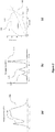
- Figure 8 shows an active diffuser slab 400 incorporating leaky fibre optics.
- the fibre optics may be disposed on the surface of the slab, cast into the matrix of the slab or bonded between slabs. Where the optical fibres 410 exit the slab, they are collected into a bundle which is encapsulated in a connector such as a ferrule 420.
- the bundled fibres are illuminated by a light source 430.
- Light source 430 may be any type of light source that can stimulate the quantum dots to emit light, such as an LED, laser diode, or other type of light source.
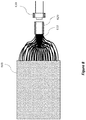
- Figure 9 shows a non-claimed embodiment of the disclosure where the quantum dots of the active diffuser are not disposed in the slab 450 or on the clad surface of the fibres 460.
- the quantum dots are coated onto the input port of ferrule 470.
- Coating 480 containing the quantum dots may be applied to the polished end surface of the leaky optical fibres 460 at the end of ferrule 470, or to a window incorporated in ferrule 470.
- Light for light source 490 is selected to stimulate the emission of the quantum dots.
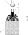
- Figure 10 shows another non claimed embodiment of the disclosure where the quantum dots of the active diffuser are not disposed in the slab 450 or on the clad surface of the fibres 460 or on the input to the ferrule 470.
- the quantum dots 530 are coated onto the surface of light source 540 which may be an LED or laser diode, or similar type of light source.
- Coating 480 containing the quantum dots may be applied to the polished end surface of the LED, or to a window incorporated in light source 540.
- Light for light source 540 is selected to stimulate the emission of the quantum dots.
- Figure 11 shows an example of an optical coupler 580 disposed between the light source 590 and active diffuser fibre optic input ferrule 570.
- Optical couplers are for coupling light sources and fibre bundles or liquid light guides. They are used to homogenize light input and can be found in scientific instruments, digital projectors, etc.
- a common form of optical coupler is a rod of glass or other transparent material. Some optical couplers are square or hexagonal in cross section, while some are circular. Some optical couplers rely on total internal reflection and some rely on coated surfaces.
- Figure 11 shows an optical coupler that is hexagonal in cross section and is composed of a transmissive substrate with quantum dots mixed into it.
- the optical coupler has a reflective coating on the surface of the rod, and filters on the end of the rod to select which wavelengths enter or leave the rod.
- Light source 590 is selected to stimulate the quantum dots in the rod matrix.
- the filter coating on the input of the rod is selected to transmit the exciting wavelengths of light and reflect the emission of the quantum dots.
- the filter coating on the distal end of the rod connecting to the fibre optic bundle ferrule 570 is selected to transmit the quantum dot emission but reflect the excitation wavelengths of light source 590.
- each slab can be selected to emit a different wavelength or range of wavelengths to augment or correct the emission from the primary luminaire.
- slab 610 might emit green light
- slab 615 might emit yellow light
- slab 620 might emit red light when the quantum dots of those slabs are stimulated. Since the same wavelength of light can be used to stimulate all the quantum dots, in order to prevent-cross stimulation between layers we can add a dichroic coating that blocks the excitation wavelength but allows the wavelengths emitted by a particular slab and the slab above it to pass through.
- Dichroic coatings 600, 645, 650, 655 can be selected to optimize transmission and reflection at each layer.
- Figure 13 shows a cross section of an active diffuser combining multiple transparent layers and dichroic coatings and how light enters and is augmented by the active diffuser.
- Luminaire 700 emits primary LED illumination 705.
- Primary LED illumination 705 passes through dichroic coating 710 and proximal active diffuser layer 715, then dichroic coating 720 and medial active diffuser layer 725, then dichroic coating 730 and distal active diffuser layer 735 and then final dichroic coating 740.
- the active diffusers have quantum dots of particular wavelength characteristics disposed within the active layer as previously described.
- Dichroic coatings 710, 720, 730, and 740 are designed to transmit light at wavelengths produced by the luminaire as well as light at wavelengths emitted by the quantum dots of each of the active diffuser layers. These coatings are designed to reflect light containing the wavelengths that stimulate the quantum dots to emit at their characteristic wavelengths. Since each active diffuser layer is sandwiched between dichroic coatings that reflects the wavelengths of light that stimulate the quantum dots, the amount of light emitted from each layer can be controlled individually by controlling the amount of stimulating light injected into the layer.
- Light 745 generated in active diffuser layer 715 which could for example be red light, passes through the subsequent dichroic coatings and diffuser layers, and similarly light 750 generated in active diffuser layer 725, which could for example be green light, passes through the subsequent dichroic coatings and diffuser layers, as does light 755 generated in active diffuser layer 735, which could for example be blue light, passes through the final dichroic coating, and in combination with light from each active diffuser layer and the light form the LED luminaire 700, provides the final mix of illumination light which will illuminate a scene or object.
- Figure 14 shows a cross section of an active diffuser combining multiple transparent layers and electrically conductive coatings and shows how light enters and is augmented by the active diffuser.
- Luminaire 800 emits primary LED illumination 805.
- Primary LED illumination 805 passes through electrically conductive coating 810 and proximal active diffuser layer 815, then electrically conductive coating 820 and medial active diffuser layer 825, then electrically conductive coating 830 and distal active diffuser layer 835 and then final electrically conductive coating 840.
- the active diffusers have quantum dots of particular wavelength characteristics disposed within the active layer as previously described.
- Electrically conductive coatings 810, 820, 830, and 840 are designed to transmit light at wavelengths produced by the luminaire as well as light at wavelengths emitted by the quantum dots of each of the active diffuser layers. These coatings are designed to be electrically conductive in order to transmit electrical energy to stimulate the optical emission of the quantum dots. Since each active diffuser layer is sandwiched between two electrically conductive coatings the amount of light emitted from each layer can be controlled individually by controlling either the voltage or the current provided by the power supply into the layer.
- Light 845 generated in active diffuser layer 815 passes through the subsequent electrically conductive coatings and diffuser layers, and similarly light 850 generated in active diffuser layer 825, which could for example be green light, passes through the subsequent electrically conductive coatings and diffuser layers, and similarly light 855 generated in active diffuser layer 835, which could for example be blue light, passes through the final electrically conductive coating, and in combination with light from each active diffuser layer and the light from the LED luminaire 800, provides the final mix of illumination light which will illuminate a scene or object.
- power supply 865 can control power between conductive layers 820 and 830
- power supply 870 can control power between conductive layers 830 and 840.
- Figures 15(a) and 15(b) show graphs of the circadian cycle and the sleep cycle.
- the circadian cycle is affected by a variety of factors but one of the more significant factors is the quantity and quality of light.
- ambient light affects the production of the hormone melatonin which helps regulate the circadian cycle.
- the active diffuser is controlled to adjust over time the relative mix of wavelengths to produce an effect on the circadian rhythms of humans, animals or plants.
Landscapes
- Physics & Mathematics (AREA)
- Engineering & Computer Science (AREA)
- General Engineering & Computer Science (AREA)
- General Physics & Mathematics (AREA)
- Optics & Photonics (AREA)
- Spectroscopy & Molecular Physics (AREA)
- Microelectronics & Electronic Packaging (AREA)
- Non-Portable Lighting Devices Or Systems Thereof (AREA)
Claims (10)
- Beleuchtungskörper, umfassend eine erste Lichtquelle (200), umfassend eine Lampe und einen aktiven Diffusor (215), der zum Konditionieren von Licht angeordnet ist, das von der Lampe ausgestrahlt wird, um räumliche Gleichförmigkeit bereitzustellen, und umfassend eine zweite Lichtquelle, die zum Einspeisen zusätzlicher Beleuchtung bei einer oder mehreren Wellenlängen angeordnet ist;
wobei die zweite Lichtquelle Quantenpunkte und eine oder mehrere Energiequellen (340) umfasst, die angeordnet sind, die Quantenpunkte zu stimulieren, Licht auszustrahlen; und eine Platte (310) aus optisch transparentem oder durchscheinendem Material umfasst und die Quantenpunkte innerhalb der Platte verteilt sind;
dadurch gekennzeichnet, dass:eine im Wesentlichen optisch klare und elektrisch leitfähige Beschichtung (315, 320) auf oberen und unteren Oberflächen der Platte (310) aufgebracht ist und mit einer Energiequelle (340) verbunden ist, um ein elektrisches Feld zu erzeugen, das steuerbar die Quantenpunkte stimulieren kann, Licht auszustrahlen;und wobei der Beleuchtungskörper weiter ein Steuersystem (220) umfasst, das selektiv wählt, welche Quantenpunkte stimuliert werden, Licht auszustrahlen;und wobei der Beleuchtungskörper weiter einen Sensor (225) zum Detektieren von Licht, das von der Lampe und/oder von dem Beleuchtungskörper ausgestrahlt wird, und zum Bestimmen seiner relativen Wellenlängenzusammensetzung und Intensität umfasst; wobei der Sensor (225) auf einer Oberfläche des Diffusors (215) oder innerhalb des Diffusors (215) angebracht ist;wobei das Steuersystem (220) das Licht, das von der zweiten Lichtquelle ausgestrahlt wird, in Reaktion auf Daten von den Sensoren (225) einstellt. - Beleuchtungskörper nach Anspruch 1, wobei lecke Lichtleitfasern (350, 375, 395, 410, 460, 510, 560) in der Platte (310) eingebettet oder entlang ihrer Oberfläche angebracht sind.
- Beleuchtungskörper nach Anspruch 2, wobei die lecken Lichtleitfasern (350, 375, 395, 410, 460, 510, 560) orthogonal angeordnet sind und ein Gitter bilden können; oder in parallelen Linien angeordnet sind; oder als eine gewebte Mattenstruktur (385) angeordnet sind.
- Beleuchtungskörper nach Anspruch 2 oder Anspruch 3, wobei die Enden der einzelnen Lichtleitfasern (350, 375, 395, 410, 460, 510, 560) am Rand der Platte zu einem Faserbündel (410, 460, 510, 560) zusammengefasst sind; wobei das Faserbündel (410, 460, 510, 560) mit einer Lichtquelle (430, 490, 540, 590) verbunden ist, die Licht in die Lichtleitfasern (350, 375, 395, 410, 460, 510, 560) des Faserbündels (410, 460, 510, 560) lenkt; und ein optischer Koppler (470, 520, 570) bereitgestellt ist, der die Lichtquelle (430, 490, 540, 590) mit dem Faserbündel (410, 460, 510, 560) verbindet.
- Beleuchtungskörper nach einem der Ansprüche 2 bis 4, umfassend eine Beschichtung (392) auf den lecken Lichtleitfasern (350, 375, 395, 410, 460, 510, 560), wobei Quantenpunkte darin verteilt sind oder die Beschichtung (392) bilden.
- Beleuchtungskörper nach Anspruch 4 oder Anspruch 5, wobei Quantenpunkte zwischen der Energiequelle (340) und einem optischen Eingang zum Lichtleitfaserbündel (410, 460, 510, 560) angebracht sind.
- Beleuchtungskörper nach einem der vorstehenden Ansprüche, wobei die zweite Lichtquelle eine Vielzahl von Platten (610, 615, 620, 715, 725, 735) umfasst, die jeweils Quantenpunkte zum Ausstrahlen einer anderen Farbe umfassen.
- Beleuchtungskörper nach einem der vorstehenden Ansprüche, wobei basierend auf den Sensorablesungen die Menge und die Wellenlängen von Licht eingestellt sind, um die natürlichen Biorhythmen des menschlichen Körpers zu beeinflussen, um Biorhythmen zum Fördern eines Wachzustands oder zum Herbeiführen von Schläfrigkeit leicht zu verschieben.
- Beleuchtungskörper nach einem der vorstehenden Ansprüche, wobei der aktive Diffusor gesteuert ist, um im Laufe der Zeit die relative Mischung von Wellenlängen einzustellen, um eine Wirkung auf die Biorhythmen von Menschen, Tieren oder Pflanzen zu erzeugen.
- Beleuchtungskörper nach Anspruch 9, wobei das Licht, das von der zweiten Lichtquelle ausgestrahlt wird, eingestellt ist, um sicherzustellen, dass Licht, das aus dem Beleuchtungskörper ausgestrahlt wird, im Laufe der Zeit beständig oder konstant ist, und/oder um Lampenalterungseffekte zu korrigieren.
Applications Claiming Priority (2)
| Application Number | Priority Date | Filing Date | Title |
|---|---|---|---|
| GBGB1315241.8A GB201315241D0 (en) | 2013-08-27 | 2013-08-27 | Improvements in or relating to lighting |
| PCT/GB2014/052553 WO2015028781A1 (en) | 2013-08-27 | 2014-08-20 | Light diffuser |
Publications (2)
| Publication Number | Publication Date |
|---|---|
| EP3063470A1 EP3063470A1 (de) | 2016-09-07 |
| EP3063470B1 true EP3063470B1 (de) | 2019-11-06 |
Family
ID=49355956
Family Applications (1)
| Application Number | Title | Priority Date | Filing Date |
|---|---|---|---|
| EP14777742.9A Active EP3063470B1 (de) | 2013-08-27 | 2014-08-20 | Lichtdiffusor |
Country Status (4)
| Country | Link |
|---|---|
| US (2) | US10598851B2 (de) |
| EP (1) | EP3063470B1 (de) |
| GB (1) | GB201315241D0 (de) |
| WO (1) | WO2015028781A1 (de) |
Families Citing this family (14)
| Publication number | Priority date | Publication date | Assignee | Title |
|---|---|---|---|---|
| GB201315241D0 (en) * | 2013-08-27 | 2013-10-09 | Nano Lit Technologies Ltd | Improvements in or relating to lighting |
| US11244563B2 (en) | 2017-10-04 | 2022-02-08 | Resilience Magnum IP, LLC | Flow management light |
| US10510251B2 (en) | 2017-10-04 | 2019-12-17 | Resilience Magnum IP, LLC | Parking space light |
| US10677402B2 (en) | 2017-10-04 | 2020-06-09 | Resilience Magnum IP, LLC | Lighting drywall |
| US10574757B2 (en) | 2017-10-04 | 2020-02-25 | Resilience Magnum IP, LLC | Self aware lights that self-configure |
| US10251242B1 (en) | 2017-10-04 | 2019-04-02 | Resilience Magnum IP, LLC | Information and hub lights |
| US11596118B2 (en) | 2017-10-04 | 2023-03-07 | Resilience Magnum IP, LLC | Intelligent horticulture light |
| US10867486B2 (en) | 2017-10-04 | 2020-12-15 | Resilience Magnum IP, LLC | Hospitality light |
| US10408988B2 (en) * | 2017-10-04 | 2019-09-10 | Resilience Magnum IP, LLC | Techniques for enhanced diffusion lighting |
| US10794603B2 (en) | 2017-10-04 | 2020-10-06 | Resilience Magnum IP, LLC | Intelligent purifier light |
| US10473489B1 (en) | 2018-07-24 | 2019-11-12 | Valeo North America, Inc. | Fiber optic panel with integrated sensors |
| CN110702264B (zh) * | 2019-10-31 | 2024-09-17 | 浙江光塔安全科技有限公司 | 一种量子点光纤照明用的检测系统 |
| JPWO2023053318A1 (de) * | 2021-09-30 | 2023-04-06 | ||
| CN115793160A (zh) * | 2022-11-27 | 2023-03-14 | 云南大学 | 一种多光束激励的碳量子点二维光波导阵列系统及应用 |
Citations (4)
| Publication number | Priority date | Publication date | Assignee | Title |
|---|---|---|---|---|
| EP1555477A1 (de) * | 2004-01-15 | 2005-07-20 | Zumtobel Staff GmbH | Leuchte mit verschiedenfarbigen Lichtquellen sowie einer Lichtleiterplatte zum Abgeben von Mischlicht |
| US20070045524A1 (en) * | 2003-06-23 | 2007-03-01 | Advanced Optical Technologies, Llc | Intelligent solid state lighting |
| WO2011005859A2 (en) * | 2009-07-07 | 2011-01-13 | University Of Florida Research Foundation, Inc. | Stable and all solution processable quantum dot light-emitting diodes |
| US20120194068A1 (en) * | 2011-01-31 | 2012-08-02 | Lite-On Technology Corp. | Lamp having light sensor |
Family Cites Families (45)
| Publication number | Priority date | Publication date | Assignee | Title |
|---|---|---|---|---|
| US4026634A (en) | 1969-06-18 | 1977-05-31 | Ricoh Co., Ltd. | Directional light transmitting screen |
| US5356487A (en) | 1983-07-25 | 1994-10-18 | Quantum Group, Inc. | Thermally amplified and stimulated emission radiator fiber matrix burner |
| US6152588A (en) | 1994-09-28 | 2000-11-28 | Sdl, Inc. | Addressable vehicular lighting system |
| US5812252A (en) | 1995-01-31 | 1998-09-22 | Arete Associates | Fingerprint--Acquisition apparatus for access control; personal weapon and other systems controlled thereby |
| US5613751A (en) | 1995-06-27 | 1997-03-25 | Lumitex, Inc. | Light emitting panel assemblies |
| US6712481B2 (en) | 1995-06-27 | 2004-03-30 | Solid State Opto Limited | Light emitting panel assemblies |
| US7108414B2 (en) | 1995-06-27 | 2006-09-19 | Solid State Opto Limited | Light emitting panel assemblies |
| US20090123356A1 (en) | 1997-07-22 | 2009-05-14 | Blacklight Power, Inc. | Inorganic hydrogen compounds |
| US20090142257A1 (en) | 1997-07-22 | 2009-06-04 | Blacklight Power, Inc. | Inorganic hydrogen compounds and applications thereof |
| WO2000007931A2 (en) | 1998-08-03 | 2000-02-17 | Mills Randell L | Inorganic hydrogen and hydrogen polymer compounds and applications thereof |
| US20090148729A1 (en) | 1999-01-06 | 2009-06-11 | Blacklight Power Company | Inorganic-hydrogen-polymer and hydrogen-polymer compounds and applications thereof |
| US20050024849A1 (en) | 1999-02-23 | 2005-02-03 | Parker Jeffery R. | Methods of cutting or forming cavities in a substrate for use in making optical films, components or wave guides |
| US6752505B2 (en) | 1999-02-23 | 2004-06-22 | Solid State Opto Limited | Light redirecting films and film systems |
| US7364341B2 (en) | 1999-02-23 | 2008-04-29 | Solid State Opto Limited | Light redirecting films including non-interlockable optical elements |
| US6538375B1 (en) | 2000-08-17 | 2003-03-25 | General Electric Company | Oled fiber light source |
| US6546174B2 (en) | 2001-01-09 | 2003-04-08 | Polymicro Technologies, Llc. | Long length, side-emitting fiber optic cables |
| US7235792B2 (en) * | 2004-05-19 | 2007-06-26 | Carl Scott Elofson | Color-tuned volumetric light using high quantum yield nanocrystals |
| US7539882B2 (en) | 2005-05-30 | 2009-05-26 | Rambus Inc. | Self-powered devices and methods |
| US7466896B2 (en) * | 2005-10-26 | 2008-12-16 | The Hong Kong Polytechnic University | Photonic fabric display with controlled pattern, color, luminescence intensity, scattering intensity and light self-amplification |
| US20080032794A1 (en) | 2006-07-24 | 2008-02-07 | Rambus, Inc. | Partitioned game console system |
| WO2009014707A2 (en) | 2007-07-23 | 2009-01-29 | Qd Vision, Inc. | Quantum dot light enhancement substrate and lighting device including same |
| TWI397229B (zh) | 2007-11-28 | 2013-05-21 | Chun Chu Yang | 同軸長線形結構雷射二極體組配的發光裝置及其製造方法 |
| US8582943B2 (en) * | 2008-02-14 | 2013-11-12 | Schott Ag | Side-emitting step index fiber |
| US8714776B2 (en) | 2008-05-13 | 2014-05-06 | Research Triangle Institute | Porous and non-porous nanostructures and application thereof |
| US8462292B2 (en) | 2008-07-31 | 2013-06-11 | Rambus Delaware Llc | Optically transmissive substrates and light emitting assemblies and methods of making same, and methods of displaying images using the optically transmissive substrates and light emitting assemblies |
| US20100247893A1 (en) | 2009-03-25 | 2010-09-30 | Goldeneye, Inc. | High quality luminescent materials for solid state lighting applications |
| US8297818B2 (en) | 2009-06-11 | 2012-10-30 | Rambus International Ltd. | Optical system with reflectors and light pipes |
| EP2470829B1 (de) * | 2009-08-28 | 2015-10-07 | Led Illumination Holdings Llc, | Beleuchtungssysteme mit auswechselbarem beleuchtungsmodul |
| KR20120095437A (ko) | 2009-11-18 | 2012-08-28 | 램버스 인터내셔널 리미티드 | 발광다이오드를 이용한 내부 수집 반사 광학체 |
| EP2507052A4 (de) | 2009-12-03 | 2013-05-29 | Res Triangle Inst | Beleuchtungsvorrichtungen mit reflektierenden nanofasern |
| DE102009058939A1 (de) * | 2009-12-17 | 2011-06-22 | ERCO GmbH, 58507 | Leuchte |
| US8517550B2 (en) | 2010-02-15 | 2013-08-27 | Abl Ip Holding Llc | Phosphor-centric control of color of light |
| EP2383590A1 (de) * | 2010-04-30 | 2011-11-02 | Schott Ag | Flächenhaftes Beleuchtungselement |
| DE102010034774A1 (de) * | 2010-08-18 | 2012-02-23 | Trilux Gmbh & Co. Kg | Leuchte |
| KR102496406B1 (ko) | 2010-11-10 | 2023-02-06 | 나노시스, 인크. | 양자 도트 필름들, 조명 디바이스들, 및 조명 방법들 |
| DE102011017728A1 (de) * | 2011-04-28 | 2012-10-31 | Ledon Oled Lighting Gmbh & Co. Kg | Lichtabgebendes Element mit einer OLED oder QLED |
| WO2012158274A1 (en) | 2011-05-13 | 2012-11-22 | Rambus Inc. | Lighting assembly |
| US8423103B2 (en) | 2011-07-12 | 2013-04-16 | Michael J. Hennessy | Energy efficient data center |
| TW201305487A (zh) | 2011-07-13 | 2013-02-01 | Rambus Inc | 具有被控制之可配置的光改向之照明組件 |
| US20140036538A1 (en) | 2012-07-31 | 2014-02-06 | Apple Inc. | Coatings to eliminate led hot spots |
| US20140036536A1 (en) | 2012-07-31 | 2014-02-06 | Apple Inc. | Mems shutter control for a display utilizing quantum dots |
| US20140036203A1 (en) | 2012-07-31 | 2014-02-06 | Apple Inc. | Light mixture for a display utilizing quantum dots |
| US10062334B2 (en) | 2012-07-31 | 2018-08-28 | Apple Inc. | Backlight dimming control for a display utilizing quantum dots |
| GB201315241D0 (en) * | 2013-08-27 | 2013-10-09 | Nano Lit Technologies Ltd | Improvements in or relating to lighting |
| EP3066523B1 (de) * | 2013-11-05 | 2020-02-26 | Nanosys, Inc. | Rückbeleuchtungseinheit für an reduzierten lichtverlust angepasste anzeigevorrichtungen |
-
2013
- 2013-08-27 GB GBGB1315241.8A patent/GB201315241D0/en not_active Ceased
-
2014
- 2014-08-20 EP EP14777742.9A patent/EP3063470B1/de active Active
- 2014-08-20 US US14/914,603 patent/US10598851B2/en not_active Expired - Fee Related
- 2014-08-20 WO PCT/GB2014/052553 patent/WO2015028781A1/en not_active Ceased
-
2020
- 2020-03-13 US US16/818,717 patent/US11098877B2/en not_active Expired - Fee Related
Patent Citations (4)
| Publication number | Priority date | Publication date | Assignee | Title |
|---|---|---|---|---|
| US20070045524A1 (en) * | 2003-06-23 | 2007-03-01 | Advanced Optical Technologies, Llc | Intelligent solid state lighting |
| EP1555477A1 (de) * | 2004-01-15 | 2005-07-20 | Zumtobel Staff GmbH | Leuchte mit verschiedenfarbigen Lichtquellen sowie einer Lichtleiterplatte zum Abgeben von Mischlicht |
| WO2011005859A2 (en) * | 2009-07-07 | 2011-01-13 | University Of Florida Research Foundation, Inc. | Stable and all solution processable quantum dot light-emitting diodes |
| US20120194068A1 (en) * | 2011-01-31 | 2012-08-02 | Lite-On Technology Corp. | Lamp having light sensor |
Also Published As
| Publication number | Publication date |
|---|---|
| GB201315241D0 (en) | 2013-10-09 |
| WO2015028781A1 (en) | 2015-03-05 |
| US11098877B2 (en) | 2021-08-24 |
| EP3063470A1 (de) | 2016-09-07 |
| US10598851B2 (en) | 2020-03-24 |
| US20200284977A1 (en) | 2020-09-10 |
| US20160216443A1 (en) | 2016-07-28 |
Similar Documents
| Publication | Publication Date | Title |
|---|---|---|
| US11098877B2 (en) | Light diffuser | |
| US11729877B2 (en) | Lighting fixture and methods | |
| US10677981B2 (en) | Large area light source and large area luminaire | |
| US8408725B1 (en) | Remote light wavelength conversion device and associated methods | |
| US11156760B2 (en) | Lighting system utilizing waveguides with extraction feature patterns | |
| US7549782B2 (en) | Semiconductor light source configured as a light tube | |
| US20170167675A1 (en) | Linear pendant luminaire | |
| CN104755832A (zh) | 提供直接和间接照明的照明系统 | |
| CN110537056A (zh) | 照明灯具及方法 | |
| US10830405B2 (en) | Sunlight-based large area light source and large area luminaire | |
| CN113661356B (zh) | 发光设备 | |
| US20210316657A1 (en) | Lighting module | |
| CN110081378B (zh) | 一种灯具及照明设备 | |
| US12225643B2 (en) | Lighting fixture and methods | |
| WO2013010717A1 (en) | Illumination device and illumination method for adapting light to characteristic of target object | |
| TW201741589A (zh) | 車用照明模組 | |
| KR20130034873A (ko) | 색가변판을 구비한 led 조명장치 | |
| CN103090195A (zh) | 具方向性光远端激发灯组 | |
| EP4646556A1 (de) | Lichterzeugungssystem mit dreieckigem lichtleiterpaneel |
Legal Events
| Date | Code | Title | Description |
|---|---|---|---|
| PUAI | Public reference made under article 153(3) epc to a published international application that has entered the european phase |
Free format text: ORIGINAL CODE: 0009012 |
|
| 17P | Request for examination filed |
Effective date: 20160314 |
|
| AK | Designated contracting states |
Kind code of ref document: A1 Designated state(s): AL AT BE BG CH CY CZ DE DK EE ES FI FR GB GR HR HU IE IS IT LI LT LU LV MC MK MT NL NO PL PT RO RS SE SI SK SM TR |
|
| AX | Request for extension of the european patent |
Extension state: BA ME |
|
| DAX | Request for extension of the european patent (deleted) | ||
| STAA | Information on the status of an ep patent application or granted ep patent |
Free format text: STATUS: EXAMINATION IS IN PROGRESS |
|
| 17Q | First examination report despatched |
Effective date: 20170302 |
|
| GRAP | Despatch of communication of intention to grant a patent |
Free format text: ORIGINAL CODE: EPIDOSNIGR1 |
|
| STAA | Information on the status of an ep patent application or granted ep patent |
Free format text: STATUS: GRANT OF PATENT IS INTENDED |
|
| INTG | Intention to grant announced |
Effective date: 20190604 |
|
| GRAS | Grant fee paid |
Free format text: ORIGINAL CODE: EPIDOSNIGR3 |
|
| GRAA | (expected) grant |
Free format text: ORIGINAL CODE: 0009210 |
|
| STAA | Information on the status of an ep patent application or granted ep patent |
Free format text: STATUS: THE PATENT HAS BEEN GRANTED |
|
| AK | Designated contracting states |
Kind code of ref document: B1 Designated state(s): AL AT BE BG CH CY CZ DE DK EE ES FI FR GB GR HR HU IE IS IT LI LT LU LV MC MK MT NL NO PL PT RO RS SE SI SK SM TR |
|
| REG | Reference to a national code |
Ref country code: GB Ref legal event code: FG4D |
|
| RIN1 | Information on inventor provided before grant (corrected) |
Inventor name: MORGAN, SARAH Inventor name: MACKINNON, NICHOLAS |
|
| REG | Reference to a national code |
Ref country code: CH Ref legal event code: EP Ref country code: AT Ref legal event code: REF Ref document number: 1199217 Country of ref document: AT Kind code of ref document: T Effective date: 20191115 |
|
| REG | Reference to a national code |
Ref country code: DE Ref legal event code: R096 Ref document number: 602014056351 Country of ref document: DE |
|
| REG | Reference to a national code |
Ref country code: IE Ref legal event code: FG4D |
|
| REG | Reference to a national code |
Ref country code: NL Ref legal event code: FP |
|
| REG | Reference to a national code |
Ref country code: LT Ref legal event code: MG4D |
|
| PG25 | Lapsed in a contracting state [announced via postgrant information from national office to epo] |
Ref country code: SE Free format text: LAPSE BECAUSE OF FAILURE TO SUBMIT A TRANSLATION OF THE DESCRIPTION OR TO PAY THE FEE WITHIN THE PRESCRIBED TIME-LIMIT Effective date: 20191106 Ref country code: LV Free format text: LAPSE BECAUSE OF FAILURE TO SUBMIT A TRANSLATION OF THE DESCRIPTION OR TO PAY THE FEE WITHIN THE PRESCRIBED TIME-LIMIT Effective date: 20191106 Ref country code: PL Free format text: LAPSE BECAUSE OF FAILURE TO SUBMIT A TRANSLATION OF THE DESCRIPTION OR TO PAY THE FEE WITHIN THE PRESCRIBED TIME-LIMIT Effective date: 20191106 Ref country code: GR Free format text: LAPSE BECAUSE OF FAILURE TO SUBMIT A TRANSLATION OF THE DESCRIPTION OR TO PAY THE FEE WITHIN THE PRESCRIBED TIME-LIMIT Effective date: 20200207 Ref country code: NO Free format text: LAPSE BECAUSE OF FAILURE TO SUBMIT A TRANSLATION OF THE DESCRIPTION OR TO PAY THE FEE WITHIN THE PRESCRIBED TIME-LIMIT Effective date: 20200206 Ref country code: LT Free format text: LAPSE BECAUSE OF FAILURE TO SUBMIT A TRANSLATION OF THE DESCRIPTION OR TO PAY THE FEE WITHIN THE PRESCRIBED TIME-LIMIT Effective date: 20191106 Ref country code: PT Free format text: LAPSE BECAUSE OF FAILURE TO SUBMIT A TRANSLATION OF THE DESCRIPTION OR TO PAY THE FEE WITHIN THE PRESCRIBED TIME-LIMIT Effective date: 20200306 Ref country code: BG Free format text: LAPSE BECAUSE OF FAILURE TO SUBMIT A TRANSLATION OF THE DESCRIPTION OR TO PAY THE FEE WITHIN THE PRESCRIBED TIME-LIMIT Effective date: 20200206 Ref country code: FI Free format text: LAPSE BECAUSE OF FAILURE TO SUBMIT A TRANSLATION OF THE DESCRIPTION OR TO PAY THE FEE WITHIN THE PRESCRIBED TIME-LIMIT Effective date: 20191106 |
|
| PG25 | Lapsed in a contracting state [announced via postgrant information from national office to epo] |
Ref country code: RS Free format text: LAPSE BECAUSE OF FAILURE TO SUBMIT A TRANSLATION OF THE DESCRIPTION OR TO PAY THE FEE WITHIN THE PRESCRIBED TIME-LIMIT Effective date: 20191106 Ref country code: IS Free format text: LAPSE BECAUSE OF FAILURE TO SUBMIT A TRANSLATION OF THE DESCRIPTION OR TO PAY THE FEE WITHIN THE PRESCRIBED TIME-LIMIT Effective date: 20200306 Ref country code: HR Free format text: LAPSE BECAUSE OF FAILURE TO SUBMIT A TRANSLATION OF THE DESCRIPTION OR TO PAY THE FEE WITHIN THE PRESCRIBED TIME-LIMIT Effective date: 20191106 |
|
| PG25 | Lapsed in a contracting state [announced via postgrant information from national office to epo] |
Ref country code: AL Free format text: LAPSE BECAUSE OF FAILURE TO SUBMIT A TRANSLATION OF THE DESCRIPTION OR TO PAY THE FEE WITHIN THE PRESCRIBED TIME-LIMIT Effective date: 20191106 |
|
| PG25 | Lapsed in a contracting state [announced via postgrant information from national office to epo] |
Ref country code: CZ Free format text: LAPSE BECAUSE OF FAILURE TO SUBMIT A TRANSLATION OF THE DESCRIPTION OR TO PAY THE FEE WITHIN THE PRESCRIBED TIME-LIMIT Effective date: 20191106 Ref country code: EE Free format text: LAPSE BECAUSE OF FAILURE TO SUBMIT A TRANSLATION OF THE DESCRIPTION OR TO PAY THE FEE WITHIN THE PRESCRIBED TIME-LIMIT Effective date: 20191106 Ref country code: DK Free format text: LAPSE BECAUSE OF FAILURE TO SUBMIT A TRANSLATION OF THE DESCRIPTION OR TO PAY THE FEE WITHIN THE PRESCRIBED TIME-LIMIT Effective date: 20191106 Ref country code: ES Free format text: LAPSE BECAUSE OF FAILURE TO SUBMIT A TRANSLATION OF THE DESCRIPTION OR TO PAY THE FEE WITHIN THE PRESCRIBED TIME-LIMIT Effective date: 20191106 Ref country code: RO Free format text: LAPSE BECAUSE OF FAILURE TO SUBMIT A TRANSLATION OF THE DESCRIPTION OR TO PAY THE FEE WITHIN THE PRESCRIBED TIME-LIMIT Effective date: 20191106 |
|
| REG | Reference to a national code |
Ref country code: DE Ref legal event code: R097 Ref document number: 602014056351 Country of ref document: DE |
|
| REG | Reference to a national code |
Ref country code: AT Ref legal event code: MK05 Ref document number: 1199217 Country of ref document: AT Kind code of ref document: T Effective date: 20191106 |
|
| PG25 | Lapsed in a contracting state [announced via postgrant information from national office to epo] |
Ref country code: SK Free format text: LAPSE BECAUSE OF FAILURE TO SUBMIT A TRANSLATION OF THE DESCRIPTION OR TO PAY THE FEE WITHIN THE PRESCRIBED TIME-LIMIT Effective date: 20191106 Ref country code: SM Free format text: LAPSE BECAUSE OF FAILURE TO SUBMIT A TRANSLATION OF THE DESCRIPTION OR TO PAY THE FEE WITHIN THE PRESCRIBED TIME-LIMIT Effective date: 20191106 |
|
| PLBE | No opposition filed within time limit |
Free format text: ORIGINAL CODE: 0009261 |
|
| STAA | Information on the status of an ep patent application or granted ep patent |
Free format text: STATUS: NO OPPOSITION FILED WITHIN TIME LIMIT |
|
| 26N | No opposition filed |
Effective date: 20200807 |
|
| PG25 | Lapsed in a contracting state [announced via postgrant information from national office to epo] |
Ref country code: SI Free format text: LAPSE BECAUSE OF FAILURE TO SUBMIT A TRANSLATION OF THE DESCRIPTION OR TO PAY THE FEE WITHIN THE PRESCRIBED TIME-LIMIT Effective date: 20191106 Ref country code: AT Free format text: LAPSE BECAUSE OF FAILURE TO SUBMIT A TRANSLATION OF THE DESCRIPTION OR TO PAY THE FEE WITHIN THE PRESCRIBED TIME-LIMIT Effective date: 20191106 |
|
| PG25 | Lapsed in a contracting state [announced via postgrant information from national office to epo] |
Ref country code: IT Free format text: LAPSE BECAUSE OF FAILURE TO SUBMIT A TRANSLATION OF THE DESCRIPTION OR TO PAY THE FEE WITHIN THE PRESCRIBED TIME-LIMIT Effective date: 20191106 |
|
| PG25 | Lapsed in a contracting state [announced via postgrant information from national office to epo] |
Ref country code: MC Free format text: LAPSE BECAUSE OF FAILURE TO SUBMIT A TRANSLATION OF THE DESCRIPTION OR TO PAY THE FEE WITHIN THE PRESCRIBED TIME-LIMIT Effective date: 20191106 |
|
| REG | Reference to a national code |
Ref country code: CH Ref legal event code: PL |
|
| PG25 | Lapsed in a contracting state [announced via postgrant information from national office to epo] |
Ref country code: LI Free format text: LAPSE BECAUSE OF NON-PAYMENT OF DUE FEES Effective date: 20200831 Ref country code: CH Free format text: LAPSE BECAUSE OF NON-PAYMENT OF DUE FEES Effective date: 20200831 Ref country code: LU Free format text: LAPSE BECAUSE OF NON-PAYMENT OF DUE FEES Effective date: 20200820 |
|
| REG | Reference to a national code |
Ref country code: BE Ref legal event code: MM Effective date: 20200831 |
|
| PG25 | Lapsed in a contracting state [announced via postgrant information from national office to epo] |
Ref country code: IE Free format text: LAPSE BECAUSE OF NON-PAYMENT OF DUE FEES Effective date: 20200820 Ref country code: BE Free format text: LAPSE BECAUSE OF NON-PAYMENT OF DUE FEES Effective date: 20200831 |
|
| PG25 | Lapsed in a contracting state [announced via postgrant information from national office to epo] |
Ref country code: TR Free format text: LAPSE BECAUSE OF FAILURE TO SUBMIT A TRANSLATION OF THE DESCRIPTION OR TO PAY THE FEE WITHIN THE PRESCRIBED TIME-LIMIT Effective date: 20191106 Ref country code: MT Free format text: LAPSE BECAUSE OF FAILURE TO SUBMIT A TRANSLATION OF THE DESCRIPTION OR TO PAY THE FEE WITHIN THE PRESCRIBED TIME-LIMIT Effective date: 20191106 Ref country code: CY Free format text: LAPSE BECAUSE OF FAILURE TO SUBMIT A TRANSLATION OF THE DESCRIPTION OR TO PAY THE FEE WITHIN THE PRESCRIBED TIME-LIMIT Effective date: 20191106 |
|
| PG25 | Lapsed in a contracting state [announced via postgrant information from national office to epo] |
Ref country code: MK Free format text: LAPSE BECAUSE OF FAILURE TO SUBMIT A TRANSLATION OF THE DESCRIPTION OR TO PAY THE FEE WITHIN THE PRESCRIBED TIME-LIMIT Effective date: 20191106 |
|
| PGFP | Annual fee paid to national office [announced via postgrant information from national office to epo] |
Ref country code: NL Payment date: 20220824 Year of fee payment: 9 |
|
| PGFP | Annual fee paid to national office [announced via postgrant information from national office to epo] |
Ref country code: GB Payment date: 20220817 Year of fee payment: 9 Ref country code: DE Payment date: 20220817 Year of fee payment: 9 |
|
| PGFP | Annual fee paid to national office [announced via postgrant information from national office to epo] |
Ref country code: FR Payment date: 20220818 Year of fee payment: 9 |
|
| REG | Reference to a national code |
Ref country code: DE Ref legal event code: R119 Ref document number: 602014056351 Country of ref document: DE |
|
| REG | Reference to a national code |
Ref country code: NL Ref legal event code: MM Effective date: 20230901 |
|
| GBPC | Gb: european patent ceased through non-payment of renewal fee |
Effective date: 20230820 |
|
| PG25 | Lapsed in a contracting state [announced via postgrant information from national office to epo] |
Ref country code: NL Free format text: LAPSE BECAUSE OF NON-PAYMENT OF DUE FEES Effective date: 20230901 |
|
| PG25 | Lapsed in a contracting state [announced via postgrant information from national office to epo] |
Ref country code: NL Free format text: LAPSE BECAUSE OF NON-PAYMENT OF DUE FEES Effective date: 20230901 |
|
| PG25 | Lapsed in a contracting state [announced via postgrant information from national office to epo] |
Ref country code: GB Free format text: LAPSE BECAUSE OF NON-PAYMENT OF DUE FEES Effective date: 20230820 |
|
| PG25 | Lapsed in a contracting state [announced via postgrant information from national office to epo] |
Ref country code: GB Free format text: LAPSE BECAUSE OF NON-PAYMENT OF DUE FEES Effective date: 20230820 Ref country code: FR Free format text: LAPSE BECAUSE OF NON-PAYMENT OF DUE FEES Effective date: 20230831 Ref country code: DE Free format text: LAPSE BECAUSE OF NON-PAYMENT OF DUE FEES Effective date: 20240301 |