EP3062415A1 - Mobile terminal charging device and automobile using same - Google Patents
Mobile terminal charging device and automobile using same Download PDFInfo
- Publication number
- EP3062415A1 EP3062415A1 EP14855695.4A EP14855695A EP3062415A1 EP 3062415 A1 EP3062415 A1 EP 3062415A1 EP 14855695 A EP14855695 A EP 14855695A EP 3062415 A1 EP3062415 A1 EP 3062415A1
- Authority
- EP
- European Patent Office
- Prior art keywords
- charging
- mobile terminal
- coil
- charging coil
- stop
- Prior art date
- Legal status (The legal status is an assumption and is not a legal conclusion. Google has not performed a legal analysis and makes no representation as to the accuracy of the status listed.)
- Granted
Links
- 238000009434 installation Methods 0.000 claims abstract description 65
- 230000007423 decrease Effects 0.000 abstract description 9
- 238000001514 detection method Methods 0.000 description 31
- 238000000034 method Methods 0.000 description 11
- 230000008569 process Effects 0.000 description 11
- 230000003247 decreasing effect Effects 0.000 description 3
- 229920003002 synthetic resin Polymers 0.000 description 3
- 239000000057 synthetic resin Substances 0.000 description 3
- VJYFKVYYMZPMAB-UHFFFAOYSA-N ethoprophos Chemical compound CCCSP(=O)(OCC)SCCC VJYFKVYYMZPMAB-UHFFFAOYSA-N 0.000 description 2
- 230000005540 biological transmission Effects 0.000 description 1
- 239000000919 ceramic Substances 0.000 description 1
- 230000008859 change Effects 0.000 description 1
- 238000010586 diagram Methods 0.000 description 1
- 238000011156 evaluation Methods 0.000 description 1
- 230000004907 flux Effects 0.000 description 1
- 230000006870 function Effects 0.000 description 1
- WABPQHHGFIMREM-UHFFFAOYSA-N lead(0) Chemical compound [Pb] WABPQHHGFIMREM-UHFFFAOYSA-N 0.000 description 1
- 239000002184 metal Substances 0.000 description 1
- 230000004044 response Effects 0.000 description 1
- 238000000926 separation method Methods 0.000 description 1
Images


Classifications
-
- B—PERFORMING OPERATIONS; TRANSPORTING
- B60—VEHICLES IN GENERAL
- B60R—VEHICLES, VEHICLE FITTINGS, OR VEHICLE PARTS, NOT OTHERWISE PROVIDED FOR
- B60R16/00—Electric or fluid circuits specially adapted for vehicles and not otherwise provided for; Arrangement of elements of electric or fluid circuits specially adapted for vehicles and not otherwise provided for
- B60R16/02—Electric or fluid circuits specially adapted for vehicles and not otherwise provided for; Arrangement of elements of electric or fluid circuits specially adapted for vehicles and not otherwise provided for electric constitutive elements
- B60R16/03—Electric or fluid circuits specially adapted for vehicles and not otherwise provided for; Arrangement of elements of electric or fluid circuits specially adapted for vehicles and not otherwise provided for electric constitutive elements for supply of electrical power to vehicle subsystems or for
-
- H—ELECTRICITY
- H02—GENERATION; CONVERSION OR DISTRIBUTION OF ELECTRIC POWER
- H02J—CIRCUIT ARRANGEMENTS OR SYSTEMS FOR SUPPLYING OR DISTRIBUTING ELECTRIC POWER; SYSTEMS FOR STORING ELECTRIC ENERGY
- H02J50/00—Circuit arrangements or systems for wireless supply or distribution of electric power
- H02J50/90—Circuit arrangements or systems for wireless supply or distribution of electric power involving detection or optimisation of position, e.g. alignment
-
- H—ELECTRICITY
- H02—GENERATION; CONVERSION OR DISTRIBUTION OF ELECTRIC POWER
- H02J—CIRCUIT ARRANGEMENTS OR SYSTEMS FOR SUPPLYING OR DISTRIBUTING ELECTRIC POWER; SYSTEMS FOR STORING ELECTRIC ENERGY
- H02J2310/00—The network for supplying or distributing electric power characterised by its spatial reach or by the load
- H02J2310/40—The network being an on-board power network, i.e. within a vehicle
- H02J2310/46—The network being an on-board power network, i.e. within a vehicle for ICE-powered road vehicles
-
- H—ELECTRICITY
- H02—GENERATION; CONVERSION OR DISTRIBUTION OF ELECTRIC POWER
- H02J—CIRCUIT ARRANGEMENTS OR SYSTEMS FOR SUPPLYING OR DISTRIBUTING ELECTRIC POWER; SYSTEMS FOR STORING ELECTRIC ENERGY
- H02J50/00—Circuit arrangements or systems for wireless supply or distribution of electric power
- H02J50/10—Circuit arrangements or systems for wireless supply or distribution of electric power using inductive coupling
-
- H—ELECTRICITY
- H02—GENERATION; CONVERSION OR DISTRIBUTION OF ELECTRIC POWER
- H02J—CIRCUIT ARRANGEMENTS OR SYSTEMS FOR SUPPLYING OR DISTRIBUTING ELECTRIC POWER; SYSTEMS FOR STORING ELECTRIC ENERGY
- H02J50/00—Circuit arrangements or systems for wireless supply or distribution of electric power
- H02J50/80—Circuit arrangements or systems for wireless supply or distribution of electric power involving the exchange of data, concerning supply or distribution of electric power, between transmitting devices and receiving devices
-
- H—ELECTRICITY
- H02—GENERATION; CONVERSION OR DISTRIBUTION OF ELECTRIC POWER
- H02J—CIRCUIT ARRANGEMENTS OR SYSTEMS FOR SUPPLYING OR DISTRIBUTING ELECTRIC POWER; SYSTEMS FOR STORING ELECTRIC ENERGY
- H02J7/00—Circuit arrangements for charging or depolarising batteries or for supplying loads from batteries
- H02J7/00032—Circuit arrangements for charging or depolarising batteries or for supplying loads from batteries characterised by data exchange
- H02J7/00034—Charger exchanging data with an electronic device, i.e. telephone, whose internal battery is under charge
Definitions
- the present invention relates to a mobile terminal charging device that charges mobile terminals such as mobile phones, and an automobile using same.
- the following device has been proposed as a mobile terminal charging device satisfying such a demand.
- the mobile terminal charging device includes a body case having an installation plate disposed on an upper surface thereof, a charging coil that is movably provided inside the body case so as to face the lower surface of the installation plate, a drive unit that moves the charging coil while facing the lower surface of the installation plate, and a controller that is connected to the drive unit and the charging coil.
- a plurality of detection coils is provided on the installation plate, as a position detection unit that detects the position of the mobile terminal which is installed on the upper surface of the installation plate (for example, PTL 1).
- An object of the present invention is to provide a mobile terminal charging device with excellent usability.
- a mobile terminal charging device includes a body case, a detector, a charging coil, a drive unit, a charging controller, a charging communication unit, and a memory.
- An installation plate is disposed on an upper surface of the body case.
- the detector is provided on or below the installation plate, and detects a position of a mobile terminal that is present on an upper surface of the installation plate.
- the charging coil is movably disposed inside the body case, in a state of facing a lower surface of the installation plate.
- the drive unit moves the charging coil in a state of facing the lower surface of the installation plate.
- the charging controller is connected to the drive unit and the charging coil, and the charging communication unit is connected to the charging controller and communicates with the mobile terminal.
- the memory is connected to the charging controller.
- the memory stores a first set distance for determining whether or not a difference between a position of the mobile terminal and a position of the charging coil is a first distance or more and a second set distance for determining whether or not a difference between the position of the mobile terminal and the position of the charging coil is a second distance (less than the first distance) or more, as a reference to drive the charging coil using the drive unit, at the time of resumption of charging after the start of charging. If a charging stop request and a stop reason are acquired from the mobile terminal, the charging controller stops charging and sets a determination distance between a position of the mobile terminal and a position of the charging coil, the determination distance being a reference to resume the charging, to a first set distance or a second set distance, depending on the stop reason.
- the charging controller moves the charging coil to a portion corresponding to the position of the mobile terminal which is detected by the detector, using the drive unit, and thereafter resumes charging. It is intended to achieve the intended purpose through this configuration.
- the charging coil is moved to a portion corresponding to the position of the mobile terminal which is detected by the detector, using the drive unit, thereafter charging is resumed, and excellent usability is achieved in this regard.
- charging stop is caused, for example, by a reason that the mobile terminal is slightly moved on the upper surface of the installation plate, due to the vibration and inertia resulting from the driving of the automobile.
- the charging coil is moved to a portion corresponding to the position of the mobile terminal which is detected by the detector, using the drive unit, and thereafter charging is resumed.
- charging is started in a state where the charging coil is held in its position. Then, in a case of full charging or other problems (for example, an increase in the temperature of the mobile terminal, or a decrease in the charging efficiency) occur, charging is stopped.
- the position of the mobile terminal is moved on the upper surface of the installation plate in a state where charging is stopped, it is determined that for example, another mobile terminal is placed, such that the charging coil is moved again to the position of the mobile terminal and charging is resumed.
- the mobile terminal charging device in a case where the mobile terminal charging device is installed in the interior of the automobile, there is a case where the mobile terminal is moved on the upper surface of the installation plate, in response to the driving of the automobile. In this case, if charging is resumed when the moving distance of the mobile terminal is the set distance or more, it is possible to prevent the resumption of inadvertent charging.
- steering wheel 3 is provided in front of interior 2 of automobile 1. Further, electronic device 4 that plays music and displays an image such as a car navigation image is provided on the side of steering wheel 3. Further, mobile terminal charging device 5 is provided in the rear of electronic device 4 in automobile interior 2.
- mobile terminal charging device 5 includes box-like body case 7 having installation plate 6 placed on the upper surface thereof, charging coil 8 that is provided movably in a horizontal direction in a state of facing the lower surface of installation plate 6, inside body case 7, drive unit 9 that moves charging coil 8 in the horizontal direction so as to face the lower surface of installation plate 6, and a charging controller (10 in FIG. 9 ) connected to drive unit 9 and charging coil 8.
- installation plate 6 will be described.
- installation plate 6 is formed by superimposing surface plate 11, intermediate plate 12, and back plate 13.
- Each of surface plate 11 and back plate 13 is made of synthetic resin, and intermediate plate 12 is made of ceramic.
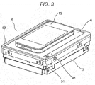
- installation plate 6 is configured to allow the magnetic flux from charging coil 8 to pass through in a direction of mobile terminal 15 placed on installation plate 6 of FIG. 3 .
- position detection coil 14 of FIG. 9 is provided on the surface of intermediate plate 12.
- Position detection coil 14 is used in PTL 1 (Japanese Patent Unexamined Publication No. 2009-247194 ), and is configured to detect a position on the upper surface of installation plate 6 where mobile terminal 15 is placed, as in FIG. 3 .
- position detection coil 14 is an example of a detector which is provided on installation plate 6, or below installation plate 6, and detects the position of mobile terminal 15 which is present on the upper surface of installation plate 6.
- the present exemplary embodiment is configured such that first, a position on the upper surface of installation plate 6 where mobile terminal 15 is placed, as in FIG. 3 , is detected using position detection coil 14, next, charging coil 8 is moved to a position facing the charging coil (15a in FIG. 9 ) of mobile terminal 15 by drive unit 9, and thereafter, charging is started.
- charging coil 8 is formed by turning a lead wire into an annular shape a plurality of times, and the circumference side and the lower surface side are held in a state in which they are covered with holder 16 made of synthetic resin.
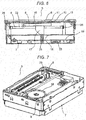
- support leg 17 extending downward towards charging coil 8 is integrally formed of synthetic resin on the lower surface of holder 16, as in FIG. 6 .
- a gap of 0.3 mm is provided between the lower surface of support leg 17 and the upper surface of metal support plate 18 that is disposed below support leg 17. Therefore, the lower surface of support leg 17 does not come into contact with the upper surface of support plate 18 during movement of charging coil 8 in a normal state.
- Control board 19, and lower plate 20 of body case 7 are disposed below support plate 18, and support body 21 passing through control board 19 is provided between the lower surface of support plate 18 and the upper surface of lower plate 20.
- installation plate 6 in a state where mobile terminal 15 is not placed on installation plate 6 of body case 7, installation plate 6 is in a state of being exposed in automobile interior 2 as in FIG. 1 .
- charging coil 8 is moved to the center of body case 7, and the above-mentioned excessive weight is supported by charging coil 8, holder 16, support leg 17, and support plate 18.
- installation plate 6 is in a state where excessive weight is applied thereto, installation plate 6 is curved downward slightly, but in this state, charging coil 8, holder 16, and support leg 17 also move downward, and the lower surface of support leg 17 comes into contact with the upper surface of support plate 18.
- the present exemplary embodiment it is configured such that the lower surface of support plate 18 is supported by lower plate 20 of body case 7 through support body 21 in order to increase the strength against the excessive weight.
- installation plate 6 elastically returns upward, and charging coil 8 and holder 16 also return upward by X-axis direction drive shaft 22 and Y-axis direction drive shaft 23 returning elastically, such that the lower surface of support leg 17 is disposed with a gap on the upper surface of support plate 18.
- drive unit 9 includes X-axis direction drive shaft 22, and Y-axis direction drive shaft 23, and the respective intermediate portions of X-axis direction drive shaft 22 and Y-axis direction drive shaft 23 are engaged with holder 16, in the outside of the charging coil hold unit of holder 16.
- a through hole (not illustrated) through which X-axis direction drive shaft 22 passes and through hole 24 through which Y-axis direction drive shaft 23 passes are provided in holder 16, with a predetermined interval in the vertical direction, in a cross-state, and X-axis direction drive shaft 22 and Y-axis direction drive shaft 23 pass through each other and are engaged.
- worm wheel 25 is provided on one end side of X-axis direction drive shaft 22, and gear 26 is provided on one end and gear 26 is also provided on the other end.
- Worm wheel 25 is engaged with worm 27, and worm 27 is connected to motor 28. Further, gears 26 on both sides are respectively engaged with gear plate 29. Therefore, if motor 28 is driven, worm 27 rotates such that worm wheel 25 and X-axis direction drive shaft 22 move in an X-axis direction, and thus charging coil 8 moves in the X-axis direction.
- worm wheel 30 is provided on one end side of Y-axis direction drive shaft 23, and gear 31 is provided on one end and gear 31 is also provided on the other end.
- Worm wheel 30 is engaged with worm 32, and worm 32 is connected to motor 33. Further, gears 31 on both sides are respectively engaged with gear plate 34. Therefore, if motor 33 is driven, worm 32 rotates such that worm wheel 30 and Y-axis direction drive shaft 23 move in a Y-axis direction, and thus charging coil 8 moves in the Y-axis direction.
- Flexible wiring 35 illustrated in FIG. 4 is provided for energizing charging coil 8, and the end of flexible wiring 35 is fixed to the side of support leg 17 described above.
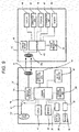
- motor 28 is connected to charging controller 10 through X-axis motor controller 36, or motor 33 is connected thereto through Y-axis motor controller 37.
- charging coil 8 is connected to charging controller 10 through charging drive circuit 38, and charging communication unit 39 that communicates information with position detection coil 14 and mobile terminal 15 installed on the upper surface of installation plate 6, memory 40, display 41 that informs the state of charging are connected to charging controller 10.
- memory 40 stores respective pieces of data of a first set distance (for example 10, mm) when a difference between the position of mobile terminal 15 and the position of charging coil 8 is a first distance or more, and a second set distance (for example, 6 mm) when a difference between the position of mobile terminal 15 and the position of charging coil 8 is a second distance (smaller than the first distance) or more, as a reference for drive unit 9 to drive charging coil 8.
- a first set distance for example 10, mm
- a second set distance for example, 6 mm
- mobile terminal 15 since mobile terminal 15 is a general device, it includes terminal charging coil 15a, and charging battery 42 and controller 43 which are connected to terminal charging coil 15a.
- controller 43 Further, display 44, operation unit 45, speaker 46, communication unit 47, memory 48, and charging communication unit 49 are connected to controller 43.
- Charging communication unit 49 communicates various types of information on charging with charging communication unit 39 of mobile terminal charging device 5, conforming to wireless power consortium (WPC).
- WPC wireless power consortium
- a charging request, a charging capacity, and the like from the mobile terminal 15 side are transmitted from charging communication unit 49 of mobile terminal 15 to charging communication unit 39 of mobile terminal charging device 5, and thus the optimal charging of charging battery 42 of mobile terminal 15 is intended to be performed.
- charging efficiency is measured on mobile terminal charging device 5 side (or mobile terminal 15 side), and if the charging efficiency of mobile terminal 15 is lower than the set efficiency value, the charging is stopped.
- charging stop is caused by a reason that charging efficiency of mobile terminal 15 is lower than the set efficiency value
- charging is intended to be resumed a predetermined number of times (for example, two times).
- charging coil 8 of mobile terminal charging device 5 and terminal charging coil 15a of mobile terminal 15 are shifted, and the second set distance (6 mm) less than the first set distance (10 mm) which is a reference at the time of full charging is used as the reference for the deviation at this time.
- charging efficiency of mobile terminal 15 is lower than the set efficiency value.
- charging is intended to be resumed (retried), for example, two times, in this state (charging efficiency decrease).
- retry counter 50 is connected to charging controller 10 of FIG. 9 .
- charging controller 10 determines that charging stop is caused by a reason that the charging efficiency of mobile terminal 15 is lower than the set efficiency value, based on charging communication information from charging communication units 39, 49, after the start of charging mobile terminal 15.
- a counter input to retry counter 50 is performed, and if the count number of retry counter 50 is the set count value (above twice) or more, it is configured to end resumption of the power supply to charging coil 8.
- position detection coil 14 detects the position of mobile terminal 15 and the position of charging coil 8.
- drive unit 9 Only when the detected position is away by the first set distance (10 mm) or more, drive unit 9 moves charging coil 8 to a portion corresponding to the position of mobile terminal 15 which is detected by position detection coil 14, and thereafter charging is resumed.
- charging controller 10 checks whether or not charging coil 8 is present at an intermediate point as in FIG. 4 , as an initialization process (S2 in FIG. 10 ).
- the checking can be determined based on the driving amounts of motors 28 and 33 that are stored in X-axis motor controller 36 and Y-axis motor controller 37.
- charging coil 8 is moved to the midpoint by charging controller 10, and is in a charging standby state at the midpoint.
- retry counter 50 is in a clear state (S3 in FIG. 10 ).
- charging controller 10 detects a position on the upper surface of installation plate 6 in which mobile terminal 15 is placed, using position detection coil 14, as in FIG. 3 (S4 and S5 in FIG. 10 ).
- the location where mobile terminal 15 is placed is actually the location of terminal charging coil 15a built into mobile terminal 15.
- charging controller 10 drives motors 28 and 33 using X-axis motor controller 36 and Y-axis motor controller 37 so as to move charging coil 8 to the detected position of terminal charging coil 15a that is provided in mobile terminal 15 (S6 in FIG. 10 ), and thereafter, starts charging using charging drive circuit 38 (S7 in FIG. 10 ).
- charging controller 10 ends the charging operation (S9 in FIG. 10 ).
- a charging request, a charging capacity, and the like from mobile terminal 15 side are transmitted from charging communication unit 49 of mobile terminal 15 to charging communication unit 39 side of mobile terminal charging device 5, and thus the optimal charging of charging battery 42 of mobile terminal 15 is intended to be performed.
- charging controller 10 (or mobile terminal 15 side) of mobile terminal charging device 5 determines whether or not the charging stop is caused by a reason that the charging efficiency of mobile terminal 15 is lower than the set efficiency value.
- drive unit 9 moves charging coil 8 to a portion corresponding to the position of mobile terminal 15 which is detected by position detection coil 14, and thereafter charging is resumed (retried).
- charging controller 10 determines whether or not charging stop is caused by "a reason that charging efficiency of mobile terminal 15 is lower than a set efficiency value", and if the result is NO, next, whether or not the position of mobile terminal 15 which is detected by position detection coil 14 and the position of charging coil 8 are separated from each other by the first set distance (10 mm) or more is determined as a condition for the start of charging (S10, S11 in FIG. 10 ).
- This state is, for example, a state where full charging is performed, and at this time, then, the presence or absence and the position of mobile terminal 15 are detected by position detection coil 14 (S12 in FIG. 10 ).
- mobile terminal 15 since mobile terminal 15 is present in the same position on installation plate 6 in the case where it becomes fully charged as described above, it becomes "Presence” in S13 of FIG. 10 , and next, since the position of mobile terminal 15 and the position of charging coil 8 are not separated from each other by the first set distance (10 mm) or more in S14 of FIG. 10 , it becomes "No” in S12 of FIG. 10 , and next, the process returns to S12 of FIG. 10 , and circulates S12, 13, 14 of FIG. 10 .
- the present exemplary embodiment it is configured to resume the charging when the fine movement of mobile terminal 15 has occurred up to two times.
- the set distance is the second set distance (6 mm)
- a determination as to whether or not the positions of mobile terminal 15 and charging coil 8 are separated from each other by the second set distance (6 mm) or more is performed.
- a condition of start of re-charging is that the position of mobile terminal 15 and the position of charging coil 8 are separated from each other by the second set distance (6 mm) or more.
- a counter input to retry counter 50 is performed (S16 of FIG. 10 ) in S16 of FIG. 10 , and next, a determination as to whether or not the count number of retry counter 50 is the set count value (for example, three times) or more is performed (S17 of FIG. 10 ), and thereafter, charging is resumed through S18, S12, S13, S14, S19, S4, and the like of FIG. 10 .
- drive unit 9 moves charging coil 8 to a portion corresponding to the position of mobile terminal 15 which is detected by position detection coil 14, and thereafter charging is resumed. Therefore, excellent usability is achieved in this regard.
- the reason for charging stop is caused by a reason that the mobile terminal is slightly moved on the upper surface of the installation plate, due to the vibration and inertia resulting from the driving of the automobile.
- position detection coil 14 is installed on installation plate 6 in the above embodiment, but position detection coil 14 may be installed below installation plate 6.
- the mobile terminal charging device since a drive unit moves the charging coil in a state of facing the lower surface of the installation plate, and thereafter charging is started, at the time of charging start, there is no concern about a location to place the mobile terminal, and excellent usability is achieved in this regard.
- the drive unit moves the charging coil to a portion corresponding to the position of the mobile terminal which is detected by the detector, and thereafter charging is resumed.
- the drive unit moves the charging coil to a portion corresponding to the position of the mobile terminal which is detected by the detector, and thereafter charging is resumed, such that excellent usability is achieved in this regard.
- the reason for charging stop is caused, for example, by a reason that the mobile terminal is slightly moved on the upper surface of the installation plate, due to the vibration and inertia resulting from the driving of the automobile, such that in this case, if the position of the mobile terminal which is detected by the detector and the position of the charging coil are separated from each other by the second set distance or more, it is configured such that the drive unit moves the charging coil to a portion corresponding to the position of the mobile terminal which is detected by the detector, and thereafter charging is resumed.
- the present invention is expected to be applied as the mobile terminal charging device for the automotive or home.
Abstract
Description
- The present invention relates to a mobile terminal charging device that charges mobile terminals such as mobile phones, and an automobile using same.
- As mobile terminals such as mobile phones have significantly advanced functions, power consumption increases.
- Therefore, charging is allowed to be performed in many places including the interior of an automobile, and so-called contactless charging without using a cable has become popular as a recent trend.
- Thus, the following device has been proposed as a mobile terminal charging device satisfying such a demand.
- In other words, the mobile terminal charging device includes a body case having an installation plate disposed on an upper surface thereof, a charging coil that is movably provided inside the body case so as to face the lower surface of the installation plate, a drive unit that moves the charging coil while facing the lower surface of the installation plate, and a controller that is connected to the drive unit and the charging coil.
- Further, a plurality of detection coils is provided on the installation plate, as a position detection unit that detects the position of the mobile terminal which is installed on the upper surface of the installation plate (for example, PTL 1).
- PTL 1: Japanese Patent Unexamined Publication No.
2009-247194 - An object of the present invention is to provide a mobile terminal charging device with excellent usability.
- A mobile terminal charging device according to a first aspect of the present invention includes a body case, a detector, a charging coil, a drive unit, a charging controller, a charging communication unit, and a memory. An installation plate is disposed on an upper surface of the body case. The detector is provided on or below the installation plate, and detects a position of a mobile terminal that is present on an upper surface of the installation plate. The charging coil is movably disposed inside the body case, in a state of facing a lower surface of the installation plate. The drive unit moves the charging coil in a state of facing the lower surface of the installation plate. The charging controller is connected to the drive unit and the charging coil, and the charging communication unit is connected to the charging controller and communicates with the mobile terminal. The memory is connected to the charging controller. The memory stores a first set distance for determining whether or not a difference between a position of the mobile terminal and a position of the charging coil is a first distance or more and a second set distance for determining whether or not a difference between the position of the mobile terminal and the position of the charging coil is a second distance (less than the first distance) or more, as a reference to drive the charging coil using the drive unit, at the time of resumption of charging after the start of charging. If a charging stop request and a stop reason are acquired from the mobile terminal, the charging controller stops charging and sets a determination distance between a position of the mobile terminal and a position of the charging coil, the determination distance being a reference to resume the charging, to a first set distance or a second set distance, depending on the stop reason. If a distance between the position of the mobile terminal which is acquired from the detector and the position of the charging coil is greater than the determination distance, the charging controller moves the charging coil to a portion corresponding to the position of the mobile terminal which is detected by the detector, using the drive unit, and thereafter resumes charging. It is intended to achieve the intended purpose through this configuration.
- Through the above configuration, it is possible to change a reference for determination as to whether or not to resume charging, depending on the reason for charging stop.
- Further, since a drive unit moves the charging coil in a state of facing the lower surface of the installation plate, and thereafter charging is started, at the time of charging start, there is no concern about a location to place the mobile terminal, and excellent usability is achieved in this regard.
- Further, at the time of charging stop after the start of charging, for example, in a case where it is determined that charging stop is caused by a reason that the charging efficiency of the mobile terminal is lower than the set efficiency value, and the position of the mobile terminal which is detected by the detector and the position of the charging coil are separated from each other by the second set distance or more, the charging coil is moved to a portion corresponding to the position of the mobile terminal which is detected by the detector, using the drive unit, thereafter charging is resumed, and excellent usability is achieved in this regard.
- In other words, since the mobile terminal is moved during driving, position deviation from the charging coil is generated, the charging efficiency decreases significantly, and thus charging stop is often generated. Therefore, during driving, since the driver is unlikely to be aware of such a charging stop, when the driver realizes the charging stop, a situation where charging is not possible may frequently occur, and this is indicated as poor usability.
- Therefore, in a case where the charging efficiency is decreased, charging stop is caused, for example, by a reason that the mobile terminal is slightly moved on the upper surface of the installation plate, due to the vibration and inertia resulting from the driving of the automobile. In this case, if the position of the mobile terminal which is detected by the detector and the position of the charging coil are separated from each other by the second set distance (less than the first set distance) or more, the charging coil is moved to a portion corresponding to the position of the mobile terminal which is detected by the detector, using the drive unit, and thereafter charging is resumed.
- Therefore, for example, since charging is performed while the charging is not inadvertently stopped during the driving of the automobile or the like, excellent usability is achieved in this regard.
-
-
FIG. 1 is a perspective view illustrating a state where a mobile terminal charging device according to an exemplary embodiment of the present invention is provided in an interior of an automobile. -
FIG. 2 is a perspective view of the mobile terminal charging device illustrated inFIG. 1 . -
FIG. 3 is a perspective view illustrating a state where a mobile terminal is placed on the mobile terminal charging device illustrated inFIG. 2 . -
FIG. 4 is a perspective view illustrating a state where a part of the mobile terminal charging device illustrated inFIG. 2 is removed. -
FIG. 5 is a plan view of the mobile terminal charging device that is in a state illustrated inFIG. 4 . -
FIG. 6 is a cross-sectional view of a broken-line part of the mobile terminal charging device illustrated inFIG. 2 . -
FIG. 7 is a perspective view illustrating another state of the mobile terminal charging device illustrated inFIG. 2 . -
FIG. 8 is a plan view of the mobile terminal charging device that is in a state illustrated inFIG. 7 . -
FIG. 9 is a control block diagram of the mobile terminal charging device illustrated inFIG. 2 . -
FIG. 10 is an operation flowchart of the mobile terminal charging device illustrated inFIG. 2 . - Prior to a description of embodiments of the present invention, problems in the example of the prior art described above will be described. In the example of the prior art, if the mobile terminal is placed on the upper surface of the installation plate, the position of the placed mobile terminal is detected by the detection coil. Since the charging coil is moved to the detected position, and charging is started in the state, there is no concern about a location to place the mobile terminal, and thus a high evaluation is achieved in this regard.
- In such a mobile terminal charging device, charging is started in a state where the charging coil is held in its position. Then, in a case of full charging or other problems (for example, an increase in the temperature of the mobile terminal, or a decrease in the charging efficiency) occur, charging is stopped.
- Further, if the position of the mobile terminal is moved on the upper surface of the installation plate in a state where charging is stopped, it is determined that for example, another mobile terminal is placed, such that the charging coil is moved again to the position of the mobile terminal and charging is resumed.
- For example, in a case where the mobile terminal charging device is installed in the interior of the automobile, there is a case where the mobile terminal is moved on the upper surface of the installation plate, in response to the driving of the automobile. In this case, if charging is resumed when the moving distance of the mobile terminal is the set distance or more, it is possible to prevent the resumption of inadvertent charging.
- However, in a case where the reason for charging stop is caused by a reason that the mobile terminal is slightly moved on the upper surface of the installation plate, due to the vibration and inertia resulting from the driving of the automobile, due to a decrease of the charging efficiency, resumption of charging improves usability.
- In other words, since the mobile terminal is moved so as to generate position deviation from the charging coil, the charging efficiency decreases significantly, and thus charging stop is often generated. Therefore, during driving, since the driver is unlikely to be aware of such a charging stop, when the driver realizes the charging stop, a situation where charging is not possible may frequently occur, and this is indicated as poor usability.
- Hereinafter, an example in which a mobile terminal charging device according to an exemplary embodiment of the present invention is installed in the interior of an automobile will be described with reference to the accompanying drawings.
- In
FIG. 1 ,steering wheel 3 is provided in front ofinterior 2 ofautomobile 1. Further,electronic device 4 that plays music and displays an image such as a car navigation image is provided on the side ofsteering wheel 3. Further, mobileterminal charging device 5 is provided in the rear ofelectronic device 4 inautomobile interior 2. - As illustrated in
FIGS. 2 to 8 , mobileterminal charging device 5 includes box-like body case 7 havinginstallation plate 6 placed on the upper surface thereof,charging coil 8 that is provided movably in a horizontal direction in a state of facing the lower surface ofinstallation plate 6, insidebody case 7,drive unit 9 that movescharging coil 8 in the horizontal direction so as to face the lower surface ofinstallation plate 6, and a charging controller (10 inFIG. 9 ) connected to driveunit 9 andcharging coil 8. - Hereinafter, respective units will be described in detail. First,
installation plate 6 will be described. - As illustrated in
FIG. 6 ,installation plate 6 is formed bysuperimposing surface plate 11,intermediate plate 12, andback plate 13. - Each of
surface plate 11 andback plate 13 is made of synthetic resin, andintermediate plate 12 is made of ceramic. In other words,installation plate 6 is configured to allow the magnetic flux fromcharging coil 8 to pass through in a direction ofmobile terminal 15 placed oninstallation plate 6 ofFIG. 3 . - Further,
position detection coil 14 ofFIG. 9 is provided on the surface ofintermediate plate 12. -
Position detection coil 14 is used in PTL 1 (Japanese Patent Unexamined Publication No.2009-247194 installation plate 6 wheremobile terminal 15 is placed, as inFIG. 3 . In other words,position detection coil 14 is an example of a detector which is provided oninstallation plate 6, or belowinstallation plate 6, and detects the position of mobile terminal 15 which is present on the upper surface ofinstallation plate 6. - The present exemplary embodiment is configured such that first, a position on the upper surface of
installation plate 6 wheremobile terminal 15 is placed, as inFIG. 3 , is detected usingposition detection coil 14, next, chargingcoil 8 is moved to a position facing the charging coil (15a inFIG. 9 ) ofmobile terminal 15 bydrive unit 9, and thereafter, charging is started. - Next, a charging
coil 8 part will be described. As will be understood fromFIGS. 4 and5 , chargingcoil 8 is formed by turning a lead wire into an annular shape a plurality of times, and the circumference side and the lower surface side are held in a state in which they are covered withholder 16 made of synthetic resin. - Further,
support leg 17 extending downward towards chargingcoil 8 is integrally formed of synthetic resin on the lower surface ofholder 16, as inFIG. 6 . - In addition, a gap of 0.3 mm is provided between the lower surface of
support leg 17 and the upper surface ofmetal support plate 18 that is disposed belowsupport leg 17. Therefore, the lower surface ofsupport leg 17 does not come into contact with the upper surface ofsupport plate 18 during movement of chargingcoil 8 in a normal state. -
Control board 19, and lower plate 20 ofbody case 7 are disposed belowsupport plate 18, andsupport body 21 passing throughcontrol board 19 is provided between the lower surface ofsupport plate 18 and the upper surface of lower plate 20. - In other words, as in
FIG. 2 , in a state wheremobile terminal 15 is not placed oninstallation plate 6 ofbody case 7,installation plate 6 is in a state of being exposed inautomobile interior 2 as inFIG. 1 . - Therefore, a situation also occurs in which the user puts their hand on
installation plate 6 by mistake, and in this case, excessive weight may be applied depending oninstallation plate 6. - Thus, in the present exemplary embodiment, as illustrated in
FIGS. 4 to 6 , chargingcoil 8 is moved to the center ofbody case 7, and the above-mentioned excessive weight is supported by chargingcoil 8,holder 16,support leg 17, andsupport plate 18. - In other words, if
installation plate 6 is in a state where excessive weight is applied thereto,installation plate 6 is curved downward slightly, but in this state, chargingcoil 8,holder 16, andsupport leg 17 also move downward, and the lower surface ofsupport leg 17 comes into contact with the upper surface ofsupport plate 18. - As a result, the excessive weight is supported by
support plate 18 throughinstallation plate 6, chargingcoil 8,holder 16, andsupport leg 17, and thus it is possible to suppress damage toinstallation plate 6 and chargingcoil 8. - In the present exemplary embodiment, it is configured such that the lower surface of
support plate 18 is supported by lower plate 20 ofbody case 7 throughsupport body 21 in order to increase the strength against the excessive weight. - Further, if such excessive weight is removed,
installation plate 6 elastically returns upward, and chargingcoil 8 andholder 16 also return upward by X-axis direction driveshaft 22 and Y-axis direction driveshaft 23 returning elastically, such that the lower surface ofsupport leg 17 is disposed with a gap on the upper surface ofsupport plate 18. - This does not become an obstacle during the following movement of charging
coil 8. - Next,
drive unit 9 will be described. As illustrated inFIGS. 4 and5 , driveunit 9 includes X-axis direction driveshaft 22, and Y-axis direction driveshaft 23, and the respective intermediate portions of X-axis direction driveshaft 22 and Y-axis direction driveshaft 23 are engaged withholder 16, in the outside of the charging coil hold unit ofholder 16. - In other words, a through hole (not illustrated) through which X-axis direction drive
shaft 22 passes and throughhole 24 through which Y-axis direction driveshaft 23 passes are provided inholder 16, with a predetermined interval in the vertical direction, in a cross-state, and X-axis direction driveshaft 22 and Y-axis direction driveshaft 23 pass through each other and are engaged. - Further,
worm wheel 25 is provided on one end side of X-axis direction driveshaft 22, andgear 26 is provided on one end andgear 26 is also provided on the other end. -
Worm wheel 25 is engaged withworm 27, andworm 27 is connected tomotor 28. Further, gears 26 on both sides are respectively engaged withgear plate 29. Therefore, ifmotor 28 is driven,worm 27 rotates such thatworm wheel 25 and X-axis direction driveshaft 22 move in an X-axis direction, and thus chargingcoil 8 moves in the X-axis direction. - Further,
worm wheel 30 is provided on one end side of Y-axis direction driveshaft 23, andgear 31 is provided on one end andgear 31 is also provided on the other end.Worm wheel 30 is engaged withworm 32, andworm 32 is connected tomotor 33. Further, gears 31 on both sides are respectively engaged withgear plate 34. Therefore, ifmotor 33 is driven,worm 32 rotates such thatworm wheel 30 and Y-axis direction driveshaft 23 move in a Y-axis direction, and thus chargingcoil 8 moves in the Y-axis direction. -
Flexible wiring 35 illustrated inFIG. 4 is provided for energizing chargingcoil 8, and the end offlexible wiring 35 is fixed to the side ofsupport leg 17 described above. - Further, as illustrated in
FIG. 9 ,motor 28 is connected to chargingcontroller 10 throughX-axis motor controller 36, ormotor 33 is connected thereto through Y-axis motor controller 37. - Further, charging
coil 8 is connected to chargingcontroller 10 through chargingdrive circuit 38, and chargingcommunication unit 39 that communicates information withposition detection coil 14 and mobile terminal 15 installed on the upper surface ofinstallation plate 6,memory 40,display 41 that informs the state of charging are connected to chargingcontroller 10. - Further,
memory 40 stores respective pieces of data of a first set distance (for example 10, mm) when a difference between the position ofmobile terminal 15 and the position of chargingcoil 8 is a first distance or more, and a second set distance (for example, 6 mm) when a difference between the position ofmobile terminal 15 and the position of chargingcoil 8 is a second distance (smaller than the first distance) or more, as a reference fordrive unit 9 to drive chargingcoil 8. - Further, since
mobile terminal 15 is a general device, it includesterminal charging coil 15a, and chargingbattery 42 andcontroller 43 which are connected toterminal charging coil 15a. - Further,
display 44,operation unit 45,speaker 46,communication unit 47,memory 48, and chargingcommunication unit 49 are connected tocontroller 43. -
Charging communication unit 49 communicates various types of information on charging with chargingcommunication unit 39 of mobileterminal charging device 5, conforming to wireless power consortium (WPC). - For example, a charging request, a charging capacity, and the like from the
mobile terminal 15 side are transmitted from chargingcommunication unit 49 of mobile terminal 15 to chargingcommunication unit 39 of mobileterminal charging device 5, and thus the optimal charging of chargingbattery 42 ofmobile terminal 15 is intended to be performed. - Further, when charging
battery 42 is fully charged, the charging is stopped, due to the charging information transmission. - Further, charging efficiency is measured on mobile
terminal charging device 5 side (or mobile terminal 15 side), and if the charging efficiency ofmobile terminal 15 is lower than the set efficiency value, the charging is stopped. - For example, when
mobile terminal 15 is moved on the upper surface ofinstallation plate 6, due to the vibration and inertia resulting from the driving ofautomobile 1, chargingcoil 8 of mobileterminal charging device 5 andterminal charging coil 15a of mobile terminal 15 enter a state of being shifted, and as a result, the charging efficiency ofmobile terminal 15 is lower than the set efficiency value, such that in this case, charging is stopped once. - Although the features of the present exemplary embodiment will be described in more detail below, for example, when charging stop is caused by a reason that charging efficiency of
mobile terminal 15 is lower than the set efficiency value, charging is intended to be resumed a predetermined number of times (for example, two times). - Further, as a condition to start re-charging, charging
coil 8 of mobileterminal charging device 5 andterminal charging coil 15a of mobile terminal 15 are shifted, and the second set distance (6 mm) less than the first set distance (10 mm) which is a reference at the time of full charging is used as the reference for the deviation at this time. - Specifically, in a case where the position of mobile terminal 15 that is detected by
position detection coil 14 and the position of chargingcoil 8 are separated from each other by the second set distance (6 mm) or more, it is configured such that first,drive unit 9moves charging coil 8 to a portion corresponding to the position of mobile terminal 15 which is detected byposition detection coil 14, and thereafter charging is resumed (retried). - Even after the charging is resumed, a determination as to whether or not the charging efficiency of
mobile terminal 15 is lower than the set efficiency value is performed. In the present exemplary embodiment, charging is intended to be resumed (retried), for example, two times, in this state (charging efficiency decrease). - In order to perform such an operation, retry
counter 50 is connected to chargingcontroller 10 ofFIG. 9 . - In other words, charging
controller 10 determines that charging stop is caused by a reason that the charging efficiency ofmobile terminal 15 is lower than the set efficiency value, based on charging communication information from chargingcommunication units mobile terminal 15. - In this case, a counter input to retry
counter 50 is performed, and if the count number of retrycounter 50 is the set count value (above twice) or more, it is configured to end resumption of the power supply to chargingcoil 8. - If charging stop is not caused by a reason that charging efficiency of
mobile terminal 15 is lower than a set efficiency value,position detection coil 14 detects the position ofmobile terminal 15 and the position of chargingcoil 8. - Only when the detected position is away by the first set distance (10 mm) or more, drive
unit 9moves charging coil 8 to a portion corresponding to the position of mobile terminal 15 which is detected byposition detection coil 14, and thereafter charging is resumed. - Hereinafter, such an operation will be described in detail. First, if
power switch 51 ofFIG. 9 andFIG. 2 is turned on (S1 inFIG. 10 ), power is supplied frompower supply 52 to chargingcontroller 10. - Thus, charging
controller 10 checks whether or not chargingcoil 8 is present at an intermediate point as inFIG. 4 , as an initialization process (S2 inFIG. 10 ). - The checking can be determined based on the driving amounts of
motors X-axis motor controller 36 and Y-axis motor controller 37. - In the case where it is determined that charging
coil 8 is not present at the midpoint, chargingcoil 8 is moved to the midpoint by chargingcontroller 10, and is in a charging standby state at the midpoint. - Next, retry
counter 50 is in a clear state (S3 inFIG. 10 ). - Thereafter, charging
controller 10 detects a position on the upper surface ofinstallation plate 6 in whichmobile terminal 15 is placed, usingposition detection coil 14, as inFIG. 3 (S4 and S5 inFIG. 10 ). - The location where
mobile terminal 15 is placed is actually the location ofterminal charging coil 15a built intomobile terminal 15. - Thereafter, charging
controller 10drives motors X-axis motor controller 36 and Y-axis motor controller 37 so as to move chargingcoil 8 to the detected position ofterminal charging coil 15a that is provided in mobile terminal 15 (S6 inFIG. 10 ), and thereafter, starts charging using charging drive circuit 38 (S7 inFIG. 10 ). - Further, during charging, it is determined whether or not charging needs to be continued (whether or not charging is completed) by the same operation as in Japanese Patent Unexamined Publication No.
2009-247194 FIG. 10 ), and if charging is completed (full charging), chargingcontroller 10 ends the charging operation (S9 inFIG. 10 ). - In other words, in the present exemplary embodiment, a charging request, a charging capacity, and the like from mobile terminal 15 side are transmitted from charging
communication unit 49 of mobile terminal 15 to chargingcommunication unit 39 side of mobileterminal charging device 5, and thus the optimal charging of chargingbattery 42 ofmobile terminal 15 is intended to be performed. - Further, in a case where such charging stop communication is performed, charging controller 10 (or mobile terminal 15 side) of mobile
terminal charging device 5 determines whether or not the charging stop is caused by a reason that the charging efficiency ofmobile terminal 15 is lower than the set efficiency value. - For example, when
mobile terminal 15 is moved on the upper surface ofinstallation plate 6, due to the vibration and inertia resulting from the driving ofautomobile 1, chargingcoil 8 of mobileterminal charging device 5 andterminal charging coil 15a of mobile terminal 15 enter a state of being shifted. - As a result, since the charging efficiency of
mobile terminal 15 is lower than the set efficiency value, in this case, charging is stopped once. - Further, in this case (where charging efficiency of
mobile terminal 15 is lower than the set efficiency value), in a condition that the position of mobile terminal 15 which is detected byposition detection coil 14 and the position of chargingcoil 8 are separated from each other by the second set distance (6 mm) or more, first,drive unit 9moves charging coil 8 to a portion corresponding to the position of mobile terminal 15 which is detected byposition detection coil 14, and thereafter charging is resumed (retried). - Even after the charging is resumed, a determination as to whether or not the charging efficiency of
mobile terminal 15 is lower than the set efficiency value is performed, but in the present exemplary embodiment, charging is intended to be resumed (retried), for example, two times, in this state (charging efficiency decrease). - If charging is stopped in S9 of
FIG. 10 , chargingcontroller 10 determines whether or not charging stop is caused by "a reason that charging efficiency ofmobile terminal 15 is lower than a set efficiency value", and if the result is NO, next, whether or not the position of mobile terminal 15 which is detected byposition detection coil 14 and the position of chargingcoil 8 are separated from each other by the first set distance (10 mm) or more is determined as a condition for the start of charging (S10, S11 inFIG. 10 ). - This state is, for example, a state where full charging is performed, and at this time, then, the presence or absence and the position of mobile terminal 15 are detected by position detection coil 14 (S12 in
FIG. 10 ). - For example, since
mobile terminal 15 is present in the same position oninstallation plate 6 in the case where it becomes fully charged as described above, it becomes "Presence" in S13 ofFIG. 10 , and next, since the position ofmobile terminal 15 and the position of chargingcoil 8 are not separated from each other by the first set distance (10 mm) or more in S14 ofFIG. 10 , it becomes "No" in S12 ofFIG. 10 , and next, the process returns to S12 ofFIG. 10 , and circulates S12, 13, 14 ofFIG. 10 . - In other words, in the full charging, the charging stop state continues.
- However, even in this fully charged state, in a case where another
mobile terminal 15 is placed oninstallation plate 6, in S13 ofFIG. 10 , the state wheremobile terminal 15 does not exist occurs, such that retrycounter 50 is cleared (S15 ofFIG. 10 ), and then the process returns to S4 ofFIG. 10 . - That is, in this process (S4 of
FIG. 10 ), the charging operation is started from the position of detecting nextmobile terminal 15. - On the contrary, if charging stop is caused by "a reason that charging efficiency of
mobile terminal 15 is lower than a set efficiency value", it becomes "Yes" in S10 ofFIG. 10 , first, the count input is performed to retry counter 50 (S16 ofFIG. 10 ), next, a determination as to whether or not the count number of retrycounter 50 is the set count value (for example, three times) or more is performed (S17 ofFIG. 10 ). - For example, when
mobile terminal 15 is moved on the upper surface ofinstallation plate 6, due to the vibration and inertia resulting from the driving ofautomobile 1, chargingcoil 8 of mobileterminal charging device 5 andterminal charging coil 15a of mobile terminal 15 enter a state of being shifted, and as a result, the charging efficiency ofmobile terminal 15 is lower than the set efficiency value, such that in this case, charging is stopped once. - However, if charging is stopped in a fine-moving state of
mobile terminal 15, charging of mobile terminal 15 inautomobile 1 becomes hard realistically. - Therefore, in the present exemplary embodiment, it is configured to resume the charging when the fine movement of
mobile terminal 15 has occurred up to two times. - In other words, if the number of fine movements of
mobile terminal 15 is equal to 2 times, in a case where the position of mobile terminal 15 which is detected byposition detection coil 14 and the position of chargingcoil 8 are separated from each other by the second set distance (6 mm) or more, it is configured such thatdrive unit 9moves charging coil 8 to a portion corresponding to the position of mobile terminal 15 which is detected byposition detection coil 14, and thereafter charging is resumed (retried) (S17 and S18 inFIG. 10 ). - In other words, at this time, in subsequent S12 of
FIG. 10 , "presence" ofmobile terminal 15 is detected byposition detection coil 14, and next, since "mobile terminal 15 presence" in (S13 ofFIG. 10 ), the process proceeds to S14 ofFIG. 10 . - Since S14 of
FIG. 10 is in a state of passing through S18 ofFIG. 10 at this time, the set distance is the second set distance (6 mm), in the process (S14 ofFIG. 10 ), a determination as to whether or not the positions ofmobile terminal 15 and chargingcoil 8 are separated from each other by the second set distance (6 mm) or more is performed. - In other words, if charging stop is caused by "a reason that the charging efficiency of
mobile terminal 15 is lower than the set efficiency value", a condition of start of re-charging is that the position ofmobile terminal 15 and the position of chargingcoil 8 are separated from each other by the second set distance (6 mm) or more. - This is likely to occur during driving of
automobile 1, as described above, and since mobile terminal 15 finely moves on the upper surface ofinstallation plate 6 at this time, separation by the second set distance (6 mm) or more is set as the setting condition. - If the position of
mobile terminal 15 and the position of chargingcoil 8 are separated from each other by the second set distance (6 mm) or more, S14 ofFIG. 10 is "Yes", the process proceeds to S19 ofFIG. 10 , in this process (S19 ofFIG. 10 ), after it is confirmed that the setting condition is the second set distance (6 mm) (Yes), the process returns to S4 ofFIG. 10 , and a recharging operation is performed. - In other words, in a state where
mobile terminal 15 is finely moved on the upper surface ofinstallation plate 6, resulting from the driving ofautomobile 1, it does not continuously become a charging stop state, and has excellent usability. - However, even though charging is resumed in this way, "a reason is that the charging efficiency of
mobile terminal 15 is lower than the set efficiency value", such that charging is stopped. - For example, in a state where a foreign object is interposed between mobile terminal 15 and the upper surface of
installation plate 6, even if charging is started again, "the reason is that the charging efficiency ofmobile terminal 15 is lower than the set efficiency value", and charging is stopped. - At this time, a counter input to retry
counter 50 is performed (S16 ofFIG. 10 ) in S16 ofFIG. 10 , and next, a determination as to whether or not the count number of retrycounter 50 is the set count value (for example, three times) or more is performed (S17 ofFIG. 10 ), and thereafter, charging is resumed through S18, S12, S13, S14, S19, S4, and the like ofFIG. 10 . - However, even if charging is resumed two times, in a state where a foreign object is interposed between mobile terminal 15 and the upper surface of
installation plate 6, "the reason is that the charging efficiency ofmobile terminal 15 is lower than the set efficiency value", and thus the charging is stopped. - Therefore, in the present exemplary embodiment, in a case where the charging resumption is caused by "a reason that the charging efficiency of
mobile terminal 15 is lower than the set efficiency value", if the recharging operation becomes the third time, a determination as to whether or not the count number of retrycounter 50 is the set count value (for example, three times) or more is "No" (S17 ofFIG. 10 ), next, such that the process proceeds to S11 ofFIG. 10 . - Then, as determination for recharging, a determination as to whether or not the position of mobile terminal 15 which is detected by
position detection coil 14 and the position of chargingcoil 8 are separated from each other by the first set distance (10 mm) or more is used (S11 ofFIG. 10 ). - Then, through S11, S12, S13 of
FIG. 10 , since the position of mobile terminal 15 which is detected byposition detection coil 14 and the position of chargingcoil 8 are not separated from each other by the first set distance (10 mm) or more in S14 ofFIG. 10 , the process returns to S12 ofFIG. 10 , and charging is stopped. - In other words, in a state where a foreign object is interposed between mobile terminal 15 and the upper surface of
installation plate 6, charging is stopped. - As described above, in the present exemplary embodiment, since
drive unit 9moves charging coil 8 in a state of facing the lower surface ofinstallation plate 6, and thereafter charging is started, at the time of charging start, there is no concern about a location to placemobile terminal 15, and excellent usability is achieved in this regard. - Further, at the time of charging stop after the start of charging, in a case where it is determined that charging stop is caused by a reason other than the reason that the charging efficiency of
mobile terminal 15 is lower than the set efficiency value, and the position of mobile terminal 15 which is detected byposition detection coil 14 and the position of chargingcoil 8 are separated from each other by the first set distance (10 mm) or more, it is configured such thatdrive unit 9moves charging coil 8 to a portion corresponding to the position of mobile terminal 15 which is detected byposition detection coil 14, and thereafter charging is resumed. - Therefore, in a state where charging is stopped, in a case where another
mobile terminal 15 is placed on the upper surface ofinstallation plate 6, again, chargingcoil 8 is moved to the position ofmobile terminal 15, charging is resumed, and excellent usability is achieved in this regard. - Further, at the time of charging stop after the start of charging, in a case where it is determined that charging stop is caused by a reason that the charging efficiency of
mobile terminal 15 is lower than the set efficiency value, and the position of mobile terminal 15 which is detected byposition detection coil 14 and the position of chargingcoil 8 are separated from each other by the second set distance (6 mm) or more, driveunit 9moves charging coil 8 to a portion corresponding to the position of mobile terminal 15 which is detected byposition detection coil 14, and thereafter charging is resumed. Therefore, excellent usability is achieved in this regard. - In other words, since
mobile terminal 15 is moved during driving so as to generate position deviation from chargingcoil 8, the charging efficiency decreases significantly, and thus charging is likely to be stopped. Therefore, the driver is not aware of such a charging stop during driving, and when the driver realizes the charging stop, the charging cannot be performed, and this is indicated as poor usability. - Therefore, in the present exemplary embodiment, for example, in a case where the charging efficiency is decreased, the reason for charging stop is caused by a reason that the mobile terminal is slightly moved on the upper surface of the installation plate, due to the vibration and inertia resulting from the driving of the automobile.
- In this case, in a condition that the position of mobile terminal 15 which is detected by
position detection coil 14 and the position of chargingcoil 8 are separated from each other by the second set distance (6 mm) or more, it is configured such thatdrive unit 9moves charging coil 8 to a portion corresponding to the position of mobile terminal 15 which is detected byposition detection coil 14, and thereafter charging is resumed. - Therefore, for example, since charging is performed while the charging is not inadvertently stopped during driving of the automobile or the like, excellent usability is achieved.
- In addition,
position detection coil 14 is installed oninstallation plate 6 in the above embodiment, butposition detection coil 14 may be installed belowinstallation plate 6. - As described above, in the mobile terminal charging device according to an embodiment of the present invention, since a drive unit moves the charging coil in a state of facing the lower surface of the installation plate, and thereafter charging is started, at the time of charging start, there is no concern about a location to place the mobile terminal, and excellent usability is achieved in this regard.
- Further, at the time of charging stop after the start of charging, in a case where it is determined that charging stop is caused by a reason other than the reason that the charging efficiency of the mobile terminal is lower than the set efficiency value, and the position of the mobile terminal which is detected by the detector and the position of the charging coil are separated from each other by the first set distance or more, the drive unit moves the charging coil to a portion corresponding to the position of the mobile terminal which is detected by the detector, and thereafter charging is resumed. Through this configuration, in a case where another mobile terminal is placed on the upper surface of the installation plate in a state where charging is stopped, the charging coil is moved again to the position of the mobile terminal, charging is resumed, and excellent usability is achieved in this regard.
- Further, at the time of charging stop after the start of charging, in a case where it is determined that charging stop is caused by a reason that the charging efficiency of the mobile terminal is lower than the set efficiency value, and the position of the mobile terminal which is detected by the detector and the position of the charging coil are separated from each other by the second set distance or more, the drive unit moves the charging coil to a portion corresponding to the position of the mobile terminal which is detected by the detector, and thereafter charging is resumed, such that excellent usability is achieved in this regard.
- In other words, during driving, since the mobile terminal is moved so as to generate position deviation from the charging coil, the charging efficiency decreases significantly, and thus charging stop is often generated. Therefore, during driving, since the driver is unlikely to be aware of such a charging stop, when the driver realizes the charging stop, a situation where charging is not possible may frequently occur, and this is indicated as poor usability.
- Therefore, in a case where the charging efficiency is decreased, the reason for charging stop is caused, for example, by a reason that the mobile terminal is slightly moved on the upper surface of the installation plate, due to the vibration and inertia resulting from the driving of the automobile, such that in this case, if the position of the mobile terminal which is detected by the detector and the position of the charging coil are separated from each other by the second set distance or more, it is configured such that the drive unit moves the charging coil to a portion corresponding to the position of the mobile terminal which is detected by the detector, and thereafter charging is resumed.
- Therefore, for example, since charging is performed while the charging is not inadvertently stopped during driving of the automobile or the like, excellent usability is achieved in this regard.
- Therefore, the present invention is expected to be applied as the mobile terminal charging device for the automotive or home.
-
- 1
- AUTOMOBILE
- 2
- AUTOMOBILE INTERIOR
- 3
- STEERING WHEEL
- 4
- ELECTRONIC DEVICE
- 5
- MOBILE TERMINAL CHARGING DEVICE
- 6
- INSTALLATION PLATE
- 7
- BODY CASE
- 8
- CHARGING COIL
- 9
- DRIVE UNIT
- 10
- CHARGING CONTROLLER
- 11
- SURFACE PLATE
- 12
- INTERMEDIATE PLATE
- 13
- BACK PLATE
- 14
- POSITION DETECTION COIL
- 15
- MOBILE TERMINAL
- 15a
- TERMINAL CHARGING COIL
- 16
- HOLDER
- 17
- SUPPORT LEG
- 18
- SUPPORT PLATE
- 19
- CONTROL BOARD
- 20
- LOWER PLATE
- 21
- SUPPORT BODY
- 22
- X-AXIS DIRECTION DRIVE SHAFT
- 23
- Y-AXIS DIRECTION DRIVE SHAFT
- 24
- THROUGH HOLE
- 25
- WORM WHEEL
- 26
- GEAR
- 27
- WORM
- 28
- MOTOR
- 29
- GEAR PLATE
- 30
- WORM WHEEL
- 31
- GEAR
- 32
- WORM
- 33
- MOTOR
- 34
- GEAR PLATE
- 35
- FLEXIBLE WIRING
- 36
- X-AXIS MOTOR CONTROLLER
- 37
- Y-AXIS MOTOR CONTROLLER
- 38
- CHARGING DRIVE CIRCUIT
- 39
- CHARGING COMMUNICATION UNIT
- 40
- MEMORY
- 41
- DISPLAY
- 42
- CHARGING BATTERY
- 43
- CONTROLLER
- 44
- DISPLAY
- 45
- OPERATION UNIT
- 46
- SPEAKER
- 47
- COMMUNICATION UNIT
- 48
- MEMORY
- 49
- CHARGING COMMUNICATION UNIT
- 50
- RETRY COUNTER
- 51
- POWER SWITCH
- 52
- POWER SUPPLY
Claims (6)
- A mobile terminal charging device comprising:a body case having an installation plate disposed on an upper surface of the body case;a detector that is provided on or below the installation plate, and detects a position of a mobile terminal that is present on an upper surface of the installation plate;a charging coil that is movably disposed inside the body case, in a state of facing a lower surface of the installation plate;a drive unit that moves the charging coil in a state of facing the lower surface of the installation plate;a charging controller that is connected to the drive unit and the charging coil; anda charging communication unit that is connected to the charging controller and communicates with the mobile terminal,wherein if a charging stop request and a stop reason are acquired from the mobile terminal, the charging controller stops charging and sets a determination distance between a position of the mobile terminal and a position of the charging coil to a first set distance or a second set distance which is less than the first set distance, depending on the stop reason, the determination distance being a reference to resume the charging, and
wherein if a distance between the position of the mobile terminal which is acquired from the detector and the position of the charging coil is greater than the determination distance, the charging controller moves the charging coil to a portion corresponding to the position of the mobile terminal which is detected by the detector, using the drive unit, and thereafter resumes charging. - The mobile terminal charging device of Claim 1,
wherein the charging controllermoves the charging coil in a state of facing the lower surface of the installation plate, using the drive unit, and thereafter resumes charging, at a time of charging start,moves the charging coil to a portion corresponding to the position of the mobile terminal which is detected by the detector, using the drive unit, and thereafter resumes charging, in a case where it is determined that charging stop is caused by a reason that charging efficiency of the mobile terminal is lower than a set efficiency value, and the position of the mobile terminal which is detected by the detector and the position of the charging coil are separated from each other by the second set distance or more, at the time of charging stop after the start of charging, andmoves the charging coil to a portion corresponding to the position of the mobile terminal which is detected by the detector, using the drive unit, and thereafter resumes charging, in a case where it is determined that charging stop is caused by a reason other than the reason that the charging efficiency of the mobile terminal is lower than the set efficiency value, and the position of the mobile terminal which is detected by the detector and the position of the charging coil are separated from each other by the first set distance or more, at the time of charging stop after the start of charging. - The mobile terminal charging device of Claim 2,
wherein a retry counter is connected to the charging controller, and
wherein the charging controller performs a count input to the retry counter in a case where it is determined that charging stop is caused by a reason that the charging efficiency of the mobile terminal is lower than the set efficiency value, after the charging start of the mobile terminal, based on charging communication information from the charging communication unit, and ends resumption of power supply to the charging coil if a count number of the retry counter is a set count value or more. - The mobile terminal charging device of Claim 3,
wherein the charging controllerstops power supply to the charging coil according to a stop request from the mobile terminal,performs a count input to the retry counter, and thereafter resumes power supply to the charging coil, in a case where it is determined that the stop request is caused by a reason that the charging efficiency of the mobile terminal is lower than the set efficiency value, andends resumption of power supply to the charging coil if the count number of the retry counter is the set count value or more. - The mobile terminal charging device of Claim 4,
wherein the charging controllerstops power supply to the charging coil according to a stop request from the mobile terminal,performs a count input to the retry counter, and sets a movable reference of the charging coil to the second set distance, in a case where it is determined that the stop request is caused by a reason that the charging efficiency of the mobile terminal is lower than the set efficiency value,moves the charging coil to the position of the mobile terminal which is detected by the detector, using the drive unit, and thereafter resumes power supply to the charging coil, in a case where it is determined that the position of the mobile terminal which is detected by the detector and the position of the charging coil are separated from each other by the second set distance or more, andends resumption of power supply to the charging coil if the count number of the retry counter is the set count value or more. - An automobile comprising:an automobile interior; andthe mobile terminal charging device according to any one of Claims 1 to 5, which is disposed in the automobile interior.
Applications Claiming Priority (2)
| Application Number | Priority Date | Filing Date | Title |
|---|---|---|---|
| JP2013218082 | 2013-10-21 | ||
| PCT/JP2014/005299 WO2015059912A1 (en) | 2013-10-21 | 2014-10-20 | Mobile terminal charging device and automobile using same |
Publications (3)
| Publication Number | Publication Date |
|---|---|
| EP3062415A1 true EP3062415A1 (en) | 2016-08-31 |
| EP3062415A4 EP3062415A4 (en) | 2016-11-23 |
| EP3062415B1 EP3062415B1 (en) | 2018-09-19 |
Family
ID=52992531
Family Applications (1)
| Application Number | Title | Priority Date | Filing Date |
|---|---|---|---|
| EP14855695.4A Active EP3062415B1 (en) | 2013-10-21 | 2014-10-20 | Mobile terminal charging device and automobile using same |
Country Status (5)
| Country | Link |
|---|---|
| US (1) | US10014711B2 (en) |
| EP (1) | EP3062415B1 (en) |
| JP (1) | JP6398087B2 (en) |
| CN (1) | CN105659468B (en) |
| WO (1) | WO2015059912A1 (en) |
Cited By (1)
| Publication number | Priority date | Publication date | Assignee | Title |
|---|---|---|---|---|
| EP3107183A3 (en) * | 2015-06-19 | 2016-12-28 | Samsung Electronics Co., Ltd. | Device and method for providing notification on wireless charging state |
Families Citing this family (9)
| Publication number | Priority date | Publication date | Assignee | Title |
|---|---|---|---|---|
| CN105006893A (en) * | 2015-05-25 | 2015-10-28 | 福建联迪商用设备有限公司 | Charging system of wireless password keyboard, and charging base |
| US10688874B2 (en) * | 2016-06-14 | 2020-06-23 | Intel Corporation | Vehicular inductive power transfer systems and methods |
| US10790703B2 (en) * | 2016-12-19 | 2020-09-29 | Koji Yoden | Smart wireless power transfer between devices |
| US10566822B2 (en) | 2017-07-28 | 2020-02-18 | Toyota Motor Engineering & Manufacturing North America, Inc. | Providing a movable charging coil |
| WO2020130162A1 (en) * | 2017-12-15 | 2020-06-25 | 경문건 | Autonomous wireless charging system and method based on power loss tracking |
| CN110893778A (en) * | 2018-08-22 | 2020-03-20 | 郑州宇通客车股份有限公司 | Dynamic wireless charging method and device for electric automobile |
| JP7253996B2 (en) | 2019-07-29 | 2023-04-07 | 株式会社Subaru | In-vehicle non-contact charging device and vehicle |
| WO2023249085A1 (en) * | 2022-06-24 | 2023-12-28 | パナソニックIpマネジメント株式会社 | Charging device |
| KR102644778B1 (en) * | 2023-02-10 | 2024-03-08 | 주식회사 스마트아이디어 | Smart device charging storage |
Family Cites Families (15)
| Publication number | Priority date | Publication date | Assignee | Title |
|---|---|---|---|---|
| JP2008109762A (en) * | 2006-10-24 | 2008-05-08 | Olympus Imaging Corp | Power transmission device |
| US20090001941A1 (en) * | 2007-06-29 | 2009-01-01 | Microsoft Corporation | Inductive Powering Surface for Powering Portable Devices |
| JP4788693B2 (en) * | 2007-09-26 | 2011-10-05 | セイコーエプソン株式会社 | Structure |
| JP5362330B2 (en) * | 2007-12-18 | 2013-12-11 | 三洋電機株式会社 | Charging stand |
| JP2009189087A (en) * | 2008-02-04 | 2009-08-20 | Fujifilm Corp | Non-contact charger |
| KR20100130215A (en) * | 2008-03-17 | 2010-12-10 | 파우워매트 엘티디. | Inductive transmission system |
| NZ593750A (en) * | 2009-01-06 | 2013-09-27 | Access Business Group Int Llc | Inductive power supply |
| US9407327B2 (en) * | 2009-02-13 | 2016-08-02 | Qualcomm Incorporated | Wireless power for chargeable and charging devices |
| EP2410630B1 (en) * | 2009-03-17 | 2016-09-28 | Fujitsu Limited | Wireless power supply system |
| JP5362453B2 (en) * | 2009-06-16 | 2013-12-11 | 三洋電機株式会社 | Charging stand |
| JP5635983B2 (en) * | 2009-06-25 | 2014-12-03 | タナシン電機株式会社 | Two-dimensional moving mechanism |
| US8525471B2 (en) * | 2009-12-28 | 2013-09-03 | Toyoda Gosei Co., Ltd | Moveable magnet and panel assembly useful in a vehicle |
| JP5713874B2 (en) * | 2011-11-14 | 2015-05-07 | 株式会社Nttドコモ | Wireless charger, foreign object detection method |
| JP6002931B2 (en) * | 2011-12-07 | 2016-10-05 | パナソニックIpマネジメント株式会社 | Car charger |
| TW201328104A (en) * | 2011-12-22 | 2013-07-01 | Primax Electronics Ltd | Wireless charger |
-
2014
- 2014-10-20 WO PCT/JP2014/005299 patent/WO2015059912A1/en active Application Filing
- 2014-10-20 US US15/026,988 patent/US10014711B2/en active Active
- 2014-10-20 CN CN201480057628.3A patent/CN105659468B/en active Active
- 2014-10-20 JP JP2015543710A patent/JP6398087B2/en active Active
- 2014-10-20 EP EP14855695.4A patent/EP3062415B1/en active Active
Cited By (1)
| Publication number | Priority date | Publication date | Assignee | Title |
|---|---|---|---|---|
| EP3107183A3 (en) * | 2015-06-19 | 2016-12-28 | Samsung Electronics Co., Ltd. | Device and method for providing notification on wireless charging state |
Also Published As
| Publication number | Publication date |
|---|---|
| CN105659468B (en) | 2018-09-11 |
| JPWO2015059912A1 (en) | 2017-03-09 |
| US20160261135A1 (en) | 2016-09-08 |
| CN105659468A (en) | 2016-06-08 |
| EP3062415B1 (en) | 2018-09-19 |
| WO2015059912A1 (en) | 2015-04-30 |
| US10014711B2 (en) | 2018-07-03 |
| EP3062415A4 (en) | 2016-11-23 |
| JP6398087B2 (en) | 2018-10-03 |
Similar Documents
| Publication | Publication Date | Title |
|---|---|---|
| EP3062415B1 (en) | Mobile terminal charging device and automobile using same | |
| EP3065262B1 (en) | Mobile-terminal charging device, and vehicle provided with same | |
| EP3121924B1 (en) | Portable terminal charging apparatus and automobile having portable terminal charging apparatus mounted therein | |
| WO2015177994A1 (en) | Mobile-terminal-charging device and vehicle in which same is mounted | |
| JP6226302B2 (en) | Non-contact charging device, program thereof, and automobile using the same | |
| JP6364625B2 (en) | Non-contact charger, its program, and car equipped with it | |
| EP3007308B1 (en) | Mobile terminal charging device, and vehicle using same | |
| US20160056661A1 (en) | Contactless charging device, device to be charged, vehicle equipped with contactless charging device and program | |
| JPWO2017017959A1 (en) | Wireless charger | |
| JP5229414B1 (en) | Portable terminal charger and car using it | |
| EP3131179B1 (en) | Mobile terminal charging device and vehicle mounted with same | |
| JP6340559B2 (en) | Portable terminal charger and car using it | |
| JP6311132B2 (en) | Portable terminal charger and car equipped with it | |
| JP2013243906A (en) | Portable terminal charging apparatus and vehicle using the same | |
| JP2014166130A (en) | Portable terminal charging apparatus and a vehicle using the same |
Legal Events
| Date | Code | Title | Description |
|---|---|---|---|
| PUAI | Public reference made under article 153(3) epc to a published international application that has entered the european phase |
Free format text: ORIGINAL CODE: 0009012 |
|
| 17P | Request for examination filed |
Effective date: 20160331 |
|
| AK | Designated contracting states |
Kind code of ref document: A1 Designated state(s): AL AT BE BG CH CY CZ DE DK EE ES FI FR GB GR HR HU IE IS IT LI LT LU LV MC MK MT NL NO PL PT RO RS SE SI SK SM TR |
|
| AX | Request for extension of the european patent |
Extension state: BA ME |
|
| A4 | Supplementary search report drawn up and despatched |
Effective date: 20161024 |
|
| RIC1 | Information provided on ipc code assigned before grant |
Ipc: H02J 50/90 20160101ALI20161018BHEP Ipc: H02J 50/00 20160101ALI20161018BHEP Ipc: H02J 7/00 20060101AFI20161018BHEP |
|
| DAX | Request for extension of the european patent (deleted) | ||
| GRAP | Despatch of communication of intention to grant a patent |
Free format text: ORIGINAL CODE: EPIDOSNIGR1 |
|
| INTG | Intention to grant announced |
Effective date: 20180326 |
|
| GRAS | Grant fee paid |
Free format text: ORIGINAL CODE: EPIDOSNIGR3 |
|
| GRAA | (expected) grant |
Free format text: ORIGINAL CODE: 0009210 |
|
| AK | Designated contracting states |
Kind code of ref document: B1 Designated state(s): AL AT BE BG CH CY CZ DE DK EE ES FI FR GB GR HR HU IE IS IT LI LT LU LV MC MK MT NL NO PL PT RO RS SE SI SK SM TR |
|
| REG | Reference to a national code |
Ref country code: GB Ref legal event code: FG4D |
|
| REG | Reference to a national code |
Ref country code: CH Ref legal event code: EP |
|
| REG | Reference to a national code |
Ref country code: AT Ref legal event code: REF Ref document number: 1044382 Country of ref document: AT Kind code of ref document: T Effective date: 20181015 |
|
| REG | Reference to a national code |
Ref country code: IE Ref legal event code: FG4D |
|
| REG | Reference to a national code |
Ref country code: DE Ref legal event code: R096 Ref document number: 602014032753 Country of ref document: DE |
|
| REG | Reference to a national code |
Ref country code: NL Ref legal event code: MP Effective date: 20180919 |
|
| PG25 | Lapsed in a contracting state [announced via postgrant information from national office to epo] |
Ref country code: BG Free format text: LAPSE BECAUSE OF FAILURE TO SUBMIT A TRANSLATION OF THE DESCRIPTION OR TO PAY THE FEE WITHIN THE PRESCRIBED TIME-LIMIT Effective date: 20181219 Ref country code: LT Free format text: LAPSE BECAUSE OF FAILURE TO SUBMIT A TRANSLATION OF THE DESCRIPTION OR TO PAY THE FEE WITHIN THE PRESCRIBED TIME-LIMIT Effective date: 20180919 Ref country code: NO Free format text: LAPSE BECAUSE OF FAILURE TO SUBMIT A TRANSLATION OF THE DESCRIPTION OR TO PAY THE FEE WITHIN THE PRESCRIBED TIME-LIMIT Effective date: 20181219 Ref country code: RS Free format text: LAPSE BECAUSE OF FAILURE TO SUBMIT A TRANSLATION OF THE DESCRIPTION OR TO PAY THE FEE WITHIN THE PRESCRIBED TIME-LIMIT Effective date: 20180919 Ref country code: GR Free format text: LAPSE BECAUSE OF FAILURE TO SUBMIT A TRANSLATION OF THE DESCRIPTION OR TO PAY THE FEE WITHIN THE PRESCRIBED TIME-LIMIT Effective date: 20181220 Ref country code: FI Free format text: LAPSE BECAUSE OF FAILURE TO SUBMIT A TRANSLATION OF THE DESCRIPTION OR TO PAY THE FEE WITHIN THE PRESCRIBED TIME-LIMIT Effective date: 20180919 Ref country code: SE Free format text: LAPSE BECAUSE OF FAILURE TO SUBMIT A TRANSLATION OF THE DESCRIPTION OR TO PAY THE FEE WITHIN THE PRESCRIBED TIME-LIMIT Effective date: 20180919 |
|
| REG | Reference to a national code |
Ref country code: LT Ref legal event code: MG4D |
|
| PG25 | Lapsed in a contracting state [announced via postgrant information from national office to epo] |
Ref country code: LV Free format text: LAPSE BECAUSE OF FAILURE TO SUBMIT A TRANSLATION OF THE DESCRIPTION OR TO PAY THE FEE WITHIN THE PRESCRIBED TIME-LIMIT Effective date: 20180919 Ref country code: AL Free format text: LAPSE BECAUSE OF FAILURE TO SUBMIT A TRANSLATION OF THE DESCRIPTION OR TO PAY THE FEE WITHIN THE PRESCRIBED TIME-LIMIT Effective date: 20180919 Ref country code: HR Free format text: LAPSE BECAUSE OF FAILURE TO SUBMIT A TRANSLATION OF THE DESCRIPTION OR TO PAY THE FEE WITHIN THE PRESCRIBED TIME-LIMIT Effective date: 20180919 |
|
| REG | Reference to a national code |
Ref country code: AT Ref legal event code: MK05 Ref document number: 1044382 Country of ref document: AT Kind code of ref document: T Effective date: 20180919 |
|
| REG | Reference to a national code |
Ref country code: DE Ref legal event code: R084 Ref document number: 602014032753 Country of ref document: DE |
|
| PG25 | Lapsed in a contracting state [announced via postgrant information from national office to epo] |
Ref country code: IT Free format text: LAPSE BECAUSE OF FAILURE TO SUBMIT A TRANSLATION OF THE DESCRIPTION OR TO PAY THE FEE WITHIN THE PRESCRIBED TIME-LIMIT Effective date: 20180919 Ref country code: PL Free format text: LAPSE BECAUSE OF FAILURE TO SUBMIT A TRANSLATION OF THE DESCRIPTION OR TO PAY THE FEE WITHIN THE PRESCRIBED TIME-LIMIT Effective date: 20180919 Ref country code: ES Free format text: LAPSE BECAUSE OF FAILURE TO SUBMIT A TRANSLATION OF THE DESCRIPTION OR TO PAY THE FEE WITHIN THE PRESCRIBED TIME-LIMIT Effective date: 20180919 Ref country code: AT Free format text: LAPSE BECAUSE OF FAILURE TO SUBMIT A TRANSLATION OF THE DESCRIPTION OR TO PAY THE FEE WITHIN THE PRESCRIBED TIME-LIMIT Effective date: 20180919 Ref country code: IS Free format text: LAPSE BECAUSE OF FAILURE TO SUBMIT A TRANSLATION OF THE DESCRIPTION OR TO PAY THE FEE WITHIN THE PRESCRIBED TIME-LIMIT Effective date: 20190119 Ref country code: EE Free format text: LAPSE BECAUSE OF FAILURE TO SUBMIT A TRANSLATION OF THE DESCRIPTION OR TO PAY THE FEE WITHIN THE PRESCRIBED TIME-LIMIT Effective date: 20180919 Ref country code: NL Free format text: LAPSE BECAUSE OF FAILURE TO SUBMIT A TRANSLATION OF THE DESCRIPTION OR TO PAY THE FEE WITHIN THE PRESCRIBED TIME-LIMIT Effective date: 20180919 Ref country code: CZ Free format text: LAPSE BECAUSE OF FAILURE TO SUBMIT A TRANSLATION OF THE DESCRIPTION OR TO PAY THE FEE WITHIN THE PRESCRIBED TIME-LIMIT Effective date: 20180919 Ref country code: RO Free format text: LAPSE BECAUSE OF FAILURE TO SUBMIT A TRANSLATION OF THE DESCRIPTION OR TO PAY THE FEE WITHIN THE PRESCRIBED TIME-LIMIT Effective date: 20180919 |
|
| PG25 | Lapsed in a contracting state [announced via postgrant information from national office to epo] |
Ref country code: PT Free format text: LAPSE BECAUSE OF FAILURE TO SUBMIT A TRANSLATION OF THE DESCRIPTION OR TO PAY THE FEE WITHIN THE PRESCRIBED TIME-LIMIT Effective date: 20190119 Ref country code: SM Free format text: LAPSE BECAUSE OF FAILURE TO SUBMIT A TRANSLATION OF THE DESCRIPTION OR TO PAY THE FEE WITHIN THE PRESCRIBED TIME-LIMIT Effective date: 20180919 Ref country code: SK Free format text: LAPSE BECAUSE OF FAILURE TO SUBMIT A TRANSLATION OF THE DESCRIPTION OR TO PAY THE FEE WITHIN THE PRESCRIBED TIME-LIMIT Effective date: 20180919 |
|
| REG | Reference to a national code |
Ref country code: CH Ref legal event code: PL |
|
| REG | Reference to a national code |
Ref country code: DE Ref legal event code: R097 Ref document number: 602014032753 Country of ref document: DE |
|
| REG | Reference to a national code |
Ref country code: BE Ref legal event code: MM Effective date: 20181031 |
|
| PG25 | Lapsed in a contracting state [announced via postgrant information from national office to epo] |
Ref country code: LU Free format text: LAPSE BECAUSE OF NON-PAYMENT OF DUE FEES Effective date: 20181020 |
|
| REG | Reference to a national code |
Ref country code: IE Ref legal event code: MM4A |
|
| PLBE | No opposition filed within time limit |
Free format text: ORIGINAL CODE: 0009261 |
|
| STAA | Information on the status of an ep patent application or granted ep patent |
Free format text: STATUS: NO OPPOSITION FILED WITHIN TIME LIMIT |
|
| PG25 | Lapsed in a contracting state [announced via postgrant information from national office to epo] |
Ref country code: DK Free format text: LAPSE BECAUSE OF FAILURE TO SUBMIT A TRANSLATION OF THE DESCRIPTION OR TO PAY THE FEE WITHIN THE PRESCRIBED TIME-LIMIT Effective date: 20180919 Ref country code: MC Free format text: LAPSE BECAUSE OF FAILURE TO SUBMIT A TRANSLATION OF THE DESCRIPTION OR TO PAY THE FEE WITHIN THE PRESCRIBED TIME-LIMIT Effective date: 20180919 |
|
| 26N | No opposition filed |
Effective date: 20190620 |
|
| GBPC | Gb: european patent ceased through non-payment of renewal fee |
Effective date: 20181219 |
|
| PG25 | Lapsed in a contracting state [announced via postgrant information from national office to epo] |
Ref country code: BE Free format text: LAPSE BECAUSE OF NON-PAYMENT OF DUE FEES Effective date: 20181031 Ref country code: LI Free format text: LAPSE BECAUSE OF NON-PAYMENT OF DUE FEES Effective date: 20181031 Ref country code: CH Free format text: LAPSE BECAUSE OF NON-PAYMENT OF DUE FEES Effective date: 20181031 |
|
| PG25 | Lapsed in a contracting state [announced via postgrant information from national office to epo] |
Ref country code: IE Free format text: LAPSE BECAUSE OF NON-PAYMENT OF DUE FEES Effective date: 20181020 Ref country code: FR Free format text: LAPSE BECAUSE OF NON-PAYMENT OF DUE FEES Effective date: 20181119 Ref country code: SI Free format text: LAPSE BECAUSE OF FAILURE TO SUBMIT A TRANSLATION OF THE DESCRIPTION OR TO PAY THE FEE WITHIN THE PRESCRIBED TIME-LIMIT Effective date: 20180919 |
|
| PG25 | Lapsed in a contracting state [announced via postgrant information from national office to epo] |
Ref country code: GB Free format text: LAPSE BECAUSE OF NON-PAYMENT OF DUE FEES Effective date: 20181219 |
|
| PG25 | Lapsed in a contracting state [announced via postgrant information from national office to epo] |
Ref country code: MT Free format text: LAPSE BECAUSE OF NON-PAYMENT OF DUE FEES Effective date: 20181020 |
|
| PG25 | Lapsed in a contracting state [announced via postgrant information from national office to epo] |
Ref country code: TR Free format text: LAPSE BECAUSE OF FAILURE TO SUBMIT A TRANSLATION OF THE DESCRIPTION OR TO PAY THE FEE WITHIN THE PRESCRIBED TIME-LIMIT Effective date: 20180919 |
|
| PG25 | Lapsed in a contracting state [announced via postgrant information from national office to epo] |
Ref country code: CY Free format text: LAPSE BECAUSE OF FAILURE TO SUBMIT A TRANSLATION OF THE DESCRIPTION OR TO PAY THE FEE WITHIN THE PRESCRIBED TIME-LIMIT Effective date: 20180919 Ref country code: HU Free format text: LAPSE BECAUSE OF FAILURE TO SUBMIT A TRANSLATION OF THE DESCRIPTION OR TO PAY THE FEE WITHIN THE PRESCRIBED TIME-LIMIT; INVALID AB INITIO Effective date: 20141020 Ref country code: MK Free format text: LAPSE BECAUSE OF NON-PAYMENT OF DUE FEES Effective date: 20180919 |
|
| PGFP | Annual fee paid to national office [announced via postgrant information from national office to epo] |
Ref country code: DE Payment date: 20231020 Year of fee payment: 10 |
|
| REG | Reference to a national code |
Ref country code: DE Ref legal event code: R081 Ref document number: 602014032753 Country of ref document: DE Owner name: PANASONIC AUTOMOTIVE SYSTEMS CO., LTD., YOKOHA, JP Free format text: FORMER OWNER: PANASONIC INTELLECTUAL PROPERTY MANAGEMENT CO., LTD, OSAKA-SHI, OSAKA, JP |