EP3062378A1 - Fuel cell - Google Patents
Fuel cell Download PDFInfo
- Publication number
- EP3062378A1 EP3062378A1 EP14856611.0A EP14856611A EP3062378A1 EP 3062378 A1 EP3062378 A1 EP 3062378A1 EP 14856611 A EP14856611 A EP 14856611A EP 3062378 A1 EP3062378 A1 EP 3062378A1
- Authority
- EP
- European Patent Office
- Prior art keywords
- fuel cell
- impact
- outer cover
- stacked body
- impact transmission
- Prior art date
- Legal status (The legal status is an assumption and is not a legal conclusion. Google has not performed a legal analysis and makes no representation as to the accuracy of the status listed.)
- Granted
Links
Images


Classifications
-
- H—ELECTRICITY
- H01—ELECTRIC ELEMENTS
- H01M—PROCESSES OR MEANS, e.g. BATTERIES, FOR THE DIRECT CONVERSION OF CHEMICAL ENERGY INTO ELECTRICAL ENERGY
- H01M8/00—Fuel cells; Manufacture thereof
- H01M8/24—Grouping of fuel cells, e.g. stacking of fuel cells
- H01M8/2465—Details of groupings of fuel cells
- H01M8/247—Arrangements for tightening a stack, for accommodation of a stack in a tank or for assembling different tanks
- H01M8/248—Means for compression of the fuel cell stacks
-
- H—ELECTRICITY
- H01—ELECTRIC ELEMENTS
- H01M—PROCESSES OR MEANS, e.g. BATTERIES, FOR THE DIRECT CONVERSION OF CHEMICAL ENERGY INTO ELECTRICAL ENERGY
- H01M8/00—Fuel cells; Manufacture thereof
- H01M8/10—Fuel cells with solid electrolytes
- H01M8/1004—Fuel cells with solid electrolytes characterised by membrane-electrode assemblies [MEA]
-
- H—ELECTRICITY
- H01—ELECTRIC ELEMENTS
- H01M—PROCESSES OR MEANS, e.g. BATTERIES, FOR THE DIRECT CONVERSION OF CHEMICAL ENERGY INTO ELECTRICAL ENERGY
- H01M8/00—Fuel cells; Manufacture thereof
- H01M8/10—Fuel cells with solid electrolytes
- H01M8/1016—Fuel cells with solid electrolytes characterised by the electrolyte material
- H01M8/1018—Polymeric electrolyte materials
- H01M8/102—Polymeric electrolyte materials characterised by the chemical structure of the main chain of the ion-conducting polymer
- H01M8/1023—Polymeric electrolyte materials characterised by the chemical structure of the main chain of the ion-conducting polymer having only carbon, e.g. polyarylenes, polystyrenes or polybutadiene-styrenes
-
- H—ELECTRICITY
- H01—ELECTRIC ELEMENTS
- H01M—PROCESSES OR MEANS, e.g. BATTERIES, FOR THE DIRECT CONVERSION OF CHEMICAL ENERGY INTO ELECTRICAL ENERGY
- H01M8/00—Fuel cells; Manufacture thereof
- H01M8/10—Fuel cells with solid electrolytes
- H01M8/1016—Fuel cells with solid electrolytes characterised by the electrolyte material
- H01M8/1018—Polymeric electrolyte materials
- H01M8/1039—Polymeric electrolyte materials halogenated, e.g. sulfonated polyvinylidene fluorides
-
- H—ELECTRICITY
- H01—ELECTRIC ELEMENTS
- H01M—PROCESSES OR MEANS, e.g. BATTERIES, FOR THE DIRECT CONVERSION OF CHEMICAL ENERGY INTO ELECTRICAL ENERGY
- H01M8/00—Fuel cells; Manufacture thereof
- H01M8/24—Grouping of fuel cells, e.g. stacking of fuel cells
- H01M8/241—Grouping of fuel cells, e.g. stacking of fuel cells with solid or matrix-supported electrolytes
-
- H—ELECTRICITY
- H01—ELECTRIC ELEMENTS
- H01M—PROCESSES OR MEANS, e.g. BATTERIES, FOR THE DIRECT CONVERSION OF CHEMICAL ENERGY INTO ELECTRICAL ENERGY
- H01M8/00—Fuel cells; Manufacture thereof
- H01M8/24—Grouping of fuel cells, e.g. stacking of fuel cells
- H01M8/2457—Grouping of fuel cells, e.g. stacking of fuel cells with both reactants being gaseous or vaporised
-
- H—ELECTRICITY
- H01—ELECTRIC ELEMENTS
- H01M—PROCESSES OR MEANS, e.g. BATTERIES, FOR THE DIRECT CONVERSION OF CHEMICAL ENERGY INTO ELECTRICAL ENERGY
- H01M8/00—Fuel cells; Manufacture thereof
- H01M8/10—Fuel cells with solid electrolytes
- H01M2008/1095—Fuel cells with polymeric electrolytes
-
- H—ELECTRICITY
- H01—ELECTRIC ELEMENTS
- H01M—PROCESSES OR MEANS, e.g. BATTERIES, FOR THE DIRECT CONVERSION OF CHEMICAL ENERGY INTO ELECTRICAL ENERGY
- H01M2250/00—Fuel cells for particular applications; Specific features of fuel cell system
- H01M2250/20—Fuel cells in motive systems, e.g. vehicle, ship, plane
-
- H—ELECTRICITY
- H01—ELECTRIC ELEMENTS
- H01M—PROCESSES OR MEANS, e.g. BATTERIES, FOR THE DIRECT CONVERSION OF CHEMICAL ENERGY INTO ELECTRICAL ENERGY
- H01M2300/00—Electrolytes
- H01M2300/0017—Non-aqueous electrolytes
- H01M2300/0065—Solid electrolytes
- H01M2300/0082—Organic polymers
-
- H—ELECTRICITY
- H01—ELECTRIC ELEMENTS
- H01M—PROCESSES OR MEANS, e.g. BATTERIES, FOR THE DIRECT CONVERSION OF CHEMICAL ENERGY INTO ELECTRICAL ENERGY
- H01M8/00—Fuel cells; Manufacture thereof
- H01M8/24—Grouping of fuel cells, e.g. stacking of fuel cells
- H01M8/2465—Details of groupings of fuel cells
- H01M8/247—Arrangements for tightening a stack, for accommodation of a stack in a tank or for assembling different tanks
- H01M8/2475—Enclosures, casings or containers of fuel cell stacks
-
- Y—GENERAL TAGGING OF NEW TECHNOLOGICAL DEVELOPMENTS; GENERAL TAGGING OF CROSS-SECTIONAL TECHNOLOGIES SPANNING OVER SEVERAL SECTIONS OF THE IPC; TECHNICAL SUBJECTS COVERED BY FORMER USPC CROSS-REFERENCE ART COLLECTIONS [XRACs] AND DIGESTS
- Y02—TECHNOLOGIES OR APPLICATIONS FOR MITIGATION OR ADAPTATION AGAINST CLIMATE CHANGE
- Y02E—REDUCTION OF GREENHOUSE GAS [GHG] EMISSIONS, RELATED TO ENERGY GENERATION, TRANSMISSION OR DISTRIBUTION
- Y02E60/00—Enabling technologies; Technologies with a potential or indirect contribution to GHG emissions mitigation
- Y02E60/10—Energy storage using batteries
-
- Y—GENERAL TAGGING OF NEW TECHNOLOGICAL DEVELOPMENTS; GENERAL TAGGING OF CROSS-SECTIONAL TECHNOLOGIES SPANNING OVER SEVERAL SECTIONS OF THE IPC; TECHNICAL SUBJECTS COVERED BY FORMER USPC CROSS-REFERENCE ART COLLECTIONS [XRACs] AND DIGESTS
- Y02—TECHNOLOGIES OR APPLICATIONS FOR MITIGATION OR ADAPTATION AGAINST CLIMATE CHANGE
- Y02E—REDUCTION OF GREENHOUSE GAS [GHG] EMISSIONS, RELATED TO ENERGY GENERATION, TRANSMISSION OR DISTRIBUTION
- Y02E60/00—Enabling technologies; Technologies with a potential or indirect contribution to GHG emissions mitigation
- Y02E60/30—Hydrogen technology
- Y02E60/50—Fuel cells
-
- Y—GENERAL TAGGING OF NEW TECHNOLOGICAL DEVELOPMENTS; GENERAL TAGGING OF CROSS-SECTIONAL TECHNOLOGIES SPANNING OVER SEVERAL SECTIONS OF THE IPC; TECHNICAL SUBJECTS COVERED BY FORMER USPC CROSS-REFERENCE ART COLLECTIONS [XRACs] AND DIGESTS
- Y02—TECHNOLOGIES OR APPLICATIONS FOR MITIGATION OR ADAPTATION AGAINST CLIMATE CHANGE
- Y02T—CLIMATE CHANGE MITIGATION TECHNOLOGIES RELATED TO TRANSPORTATION
- Y02T90/00—Enabling technologies or technologies with a potential or indirect contribution to GHG emissions mitigation
- Y02T90/40—Application of hydrogen technology to transportation, e.g. using fuel cells
Definitions
- the present invention relates to a fuel cell.
- a proposed configuration of a fuel cell includes an elastic material such as silicon or urethane rubber that is filled between a fuel cell stack and a tension plate extended along a stacking direction of a plurality of single fuel cells constituting the fuel cell stack (Patent Literature 1).
- Another proposed configuration of a fuel cell divides a fuel cell stack into multi-cell modules, each including a plurality of single fuel cells, and fixes an end cell of each of the multi-cell modules to a binding shaft placed along a stacking direction of the fuel cell stack, so as to distribute an impact load applied to the fuel cell stack (Patent Literature 2).
- the elastic material has low rigidity and is readily deformed when an inertial force is applied to the fuel cell by an external impact or the like to press the fuel cell against the elastic material. This suppresses damage of the single fuel cells but is likely to cause positional misalignment of the respective single fuel cells. The positional misalignment between adjacent single fuel cells is likely to damage seal between the single fuel cells and cause leakage of a reactive gas or a cooling medium.
- This problem is not characteristic of the configuration that the elastic material is filled between the tension plate and the fuel cell stack but is commonly found in any configuration that the elastic material is filled between the fuel cell stack and an outer cover provided to cover the fuel cell stack, for example, a configuration that the elastic material is filled between the fuel cell stack and a casing provided to contain the fuel cell stack therein.
- a material having high rigidity is used to suppress positional misalignment caused by an external impact, however, this interferes with motion of the single fuel cell in the stacking direction due to a change in environment such as temperature or humidity. This makes it likely to apply a larger load than an expected fastening load to the stacked body and reduce the durability of the single fuel cells.
- an insulating member needs to be placed, for example, between the end cell and the binding shaft, in order to provide insulation between the respective end cells of the plurality of multi-cell modules. This need increases the number of components and thereby increases the manufacturing cost of the fuel cell.
- the invention may be implemented by any of the following aspects.
- the invention may be implemented by various aspects, for example, a method of manufacturing a fuel cell, a fuel cell system and a vehicle equipped with a fuel cell.
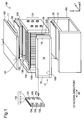
- Fig. 1 is an exploded perspective view illustrating the configuration of a fuel cell according to a first embodiment of the invention.
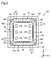
- Fig. 2 is a sectional view illustrating the fuel cell according to the first embodiment.
- Fig. 2 shows a cross section taken on a line 1-1 in Fig. 1 .
- a fuel cell 100 includes a stacked body 101, a deformation absorbing member 102, a pair of terminal plates 140, four fastening support members 130, four impact protection members 20, a first outer cover 161 and a second outer cover 162.
- the fuel cell 100 also includes four impact transmission members 10.
- the fuel cell 100 is combined with, for example, supply systems of reactive gases (fuel gas and oxidizing gas) and a supply system of a cooling medium to constitute a fuel cell system.
- This fuel cell system may be mounted on an electric vehicle or the like to be used as a system of providing power supply for driving.
- the stacked body 101 has a stacked configuration of a plurality of single fuel cells 110 along a stacking direction SD.
- the stacking direction SD of the single fuel cells 110 is parallel to X-axis direction (+X direction and -X direction).
- X-axis direction and Y-axis direction (+Y direction and -Y direction) are directions parallel to the horizontal plane; +Z direction indicates vertically upward direction; and -Z direction indicates vertically downward direction.
- the single fuel cell 110 is a polymer electrolyte fuel cell.
- the single fuel cell 110 has an approximately cubic outer shape.
- the single fuel cell 110 has a first side face S10 that forms a bottom face in the state that the fuel cell 100 is mounted, a second side face S20 that is arranged adjacent to the first side face S10, a third side face S30 that is arranged adjacent to the first side face S10 and is opposed to the second side face S20, and a fourth side face S40 that forms a top face and is opposed to the first side face S10. All these four side faces S10, S20, S30 and S40 are side faces along the stacking direction SD.
- This term "along the stacking direction SD" is used in a wide sense including a direction that crosses the stacking direction SD other than a direction perpendicular to the stacking direction SD, in addition to a direction parallel to the stacking direction SD.
- the single fuel cell 110 includes a membrane electrode assembly 111 and a pair of separators 112 and 113 arranged to place the membrane electrode assembly 111 therebetween.
- the membrane electrode assembly 111 includes an electrolyte membrane, two catalyst layers provided on respective surfaces of the electrolyte membrane, and two gas diffusion layers provided to place the electrolyte membrane and the two catalyst layers therebetween.
- the electrolyte membrane is a sulfonate group-containing fluororesin-based ion exchange membrane.
- the electrolyte membrane is, however, not limited to the sulfonate group-containing membrane but may be another ion exchange group-containing membrane such as phosphate group-containing membrane or carboxylate group-containing membrane.
- the catalyst layer is formed from a base material (catalyst carrier) in which a catalyst such as platinum or a platinum alloy is supported on a conductive carrier (for example, carbon particles).
- the gas diffusion layer is formed from a porous material.
- the porous material may be, for example, a carbon porous material such as carbon paper or a metal porous material such as metal mesh or foamed metal.
- the separator is formed from a gas-impermeable conductive material. Available examples of such material include dense carbon formed by compression of carbon to be gas impermeable and a press-molded metal plate.
- the single fuel cell 110 includes an oxidizing gas supply passage 151, an oxidizing gas exhaust passage 152, a fuel gas supply passage 153, a fuel gas exhaust passage 154, a cooling medium supply passage 155 and a cooling medium discharge passage 156.
- the stacked arrangement of the individual flow passages of the respective single fuel cells 110 in the stacking direction SD forms an oxidizing gas supply manifold, an oxidizing gas exhaust manifold, a fuel gas supply manifold, a fuel gas exhaust manifold, a cooling medium supply manifold and a cooling medium discharge manifold (not shown) in the stacked body 101.
- the deformation absorbing member 102 is provided outside of an end cell (outermost single fuel cell 110) on one side of the stacked body 101 to be placed between this end cell and the terminal plate 120.
- the deformation absorbing member 102 is made of an elastomer such as rubber and serves to absorb deformation of the stacked body 101 in the stacking direction SD caused by thermal expansion of the single fuel cells 110.
- the deformation absorbing member 102 may be formed from any elastic body such as spring, instead of the elastomer.
- one terminal plate 120 is placed outside of the deformation absorbing member 102 to be adjacent to the deformation absorbing member 102, while the other terminal plate 120 is placed outside of an end cell on a side without the deformation absorbing member 102 to be adjacent to this end cell.
- the respective terminal plates 120 serve to collect the electric current generated in the stacked body 101.
- the pair of terminal plates 120 serve to apply a predetermined fastening force in the stacking direction SD to a stacked assembly including the stacked body 101 and the deformation absorbing member 102.
- the terminal plate 120 that is not adjacent to the deformation absorbing member 102 has six connection ports 121 that are connected with the respective manifolds formed in the stacked body 101. Planes of each terminal plate 120 perpendicular to the stacking direction SD are formed in a rectangular shape.
- the four fastening support members 130 are rod-like members and are arranged between the pair of terminal plates 120 along the stacking direction SD. As shown in Fig. 2 , each fastening support member 130 is arranged to connect its corners at corresponding positions of the two terminal plates 120 with each other. The respective fastening support members 130 are connected with both the terminal plates 120 to maintain the fastening force in the stacking direction SD applied to the stacked assembly including the stacked body 101 and the deformation absorbing member 102.
- the impact transmission member 10 has an outer shape having its longitudinal direction identical with the stacking direction SD.
- the impact transmission member 10 includes a bag body 11 and a dilatant fluid 12 filled inside of the bag body 11.
- the dilatant fluid 12 is omitted from the illustration of Fig. 1 .
- the bag body 11 has a thin bag-like outer shape with an opening and includes a main wall portion 19 and a pair of side wall portions 18.
- the main wall portion 19 is arranged to face one of the four side faces S10, S20, S30 and S40 of the stacked body 101 ad to be adjacent to the impact protection member 20.
- the main wall portion 19 has a +X-direction edge connected with one side wall portion 18 and a -X-direction edge connected with the other side wall portion 18.
- the pair of side wall portions 18 are arranged to be adjacent to the respective terminal plates 120.
- the bag body 11 is made of a material having low permeability of the dilatant fluid 12. More specifically, the bag body 11 is made of polypropylene according to this embodiment. Another resin or an elastomer such as urethane may be used in place of polypropylene.
- An edge portion 190 that forms an opening of each impact transmission member 10 as shown in Fig. 1 is joined with an inner surface of the second outer cover 162 or an inner surface of the first outer cover 161 as shown in Fig. 2 .
- the opening of each impact transmission member 10 is closed by the first outer cover 161 or by the second outer cover 162. More specifically, as shown in Fig. 2 , an inner top face S1 of the second outer cover 162, two inner side faces S2 and S3 along the vertical direction of the first outer cover 161 and an inner bottom face S4 of the first outer cover 161 are respectively joined with the edge portions 190 of the bag bodies 11.
- a bonding method using an adhesive is employed to join the edge portion 190 with the inner surface of the second outer cover 162 or the inner surface of the first outer cover 161.
- the bonding method using the adhesive may be replaced by any other joining method such as welding or simple insertion.
- the dilatant fluid 12 behaves like a solid in response to an abrupt change and shows fluidity in response to a slow deformation.
- the dilatant fluid 12 is made of a material obtained by kneading and drying a mixture of silicone oil and boric acid with a small amount of a catalyst (for example, iron chloride or nickel chloride) in a high temperature environment (for example, temperature of not lower than 100 degrees Celsius).
- a catalyst for example, iron chloride or nickel chloride
- a high temperature environment for example, temperature of not lower than 100 degrees Celsius.
- available examples of such material include Dow Corning 3179 ("Dow Corning" is registered trademark) manufactured by Dow Corning Corporation and M48 and M49 manufactured by Wacker GmbH.
- each bag body 11 is closed by the first outer cover 161 or the second outer cover 162, so as to prevent leakage of the dilatant fluid 12 from the bag body 11.
- the impact protection member 20 is a thin flexible cloth member and has a rectangular outer shape having its longitudinal direction identical with the stacking direction SD.
- the impact protection member 20 is formed from Kevlar (registered trademark).
- the impact protection member 20 may be formed from any other material, such as glass fiber, having the higher rigidity than that of the bag body 11, in place of Kevlar.
- the impact protection member 20 may alternatively be formed from a material having the lower rigidity than that of the bag body 11.
- the impact protection member 20 has the lower rigidity than that of the dilatant fluid 12.
- the rigidity of the dilatant fluid 12 to be compared with the rigidity of the impact protection member 20 herein means the rigidity measured by application of a sudden impact to the impact transmission member 10.
- the impact protection member 20 is placed between the impact transmission member 10 and each side face along the stacking direction SD of the stacked body 101. More specifically, one impact protection member 20 is placed between the first side face S10 of the stacked body 101 and the impact transmission member 10 joined with the bottom face S4 of the first outer cover 161. One impact protection member 20 is placed between the second side face S20 of the stacked body 101 and the impact transmission member 10 joined with the side face S2 of the first outer cover 161. One impact protection member 20 is placed between the third side face S30 of the stacked body 101 and the impact transmission member 10 joined with the side face S3 of the first outer cover 161. One impact protection member 20 is placed between the fourth side face S40 of the stacked body 101 and the impact transmission member 10 joined with the second outer cover 162.
- each impact transmission member 10 and the corresponding impact protection member 20 are entirely bonded to each other.
- the contact areas of each impact transmission member 10 and the corresponding impact protection member 20 may be only partly bonded to each other. Such contact areas may not be bonded to each other.
- the impact protection member 20 serves to protect the bag body 11 from an impact.
- the impact protection member 20 suppresses the bag body 11 from being damaged by the corner of the single fuel cell 110 when a sudden force is applied to the fuel cell 100.
- the first outer cover 161 is formed in an outer shape of an approximately U-shaped cross section viewed in the X-axis direction.
- the length in the X-axis direction of the first outer cover 161 is approximately equal to the length in the X-axis direction of an assembly including the stacked body 101, the deformation absorbing member 102 and the pair of terminal plates 120.
- the first outer cover 161 is configured to cover the entire fuel cell 100 except the first outer cover 161 and the second outer cover 162 upward (in the +Z direction) and sideways (in the +Y direction and -Y direction).
- the second outer cover 162 is a plate-like member having its thickness direction identical with the Z-axis direction and is arrange to cover the upper opening of the first outer cover 161.
- the first outer cover 161 and the second outer cover 162 described above correspond to the fastening support member and the outer cover in the claims.
- the bag body 11 corresponds to the bag-like member in the claims.
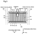
- Fig. 3 is a diagram illustrating an inertial force applied to the fuel cell 100 in the state that the fuel cell 100 is mounted on a vehicle.
- the first outer cover 161 is fixed to a side member 500 of the vehicle.
- an inertial force Fg in a traveling direction is applied to the stacked body 101 that is not directly connected with the side member 500.
- the respective single fuel cells 110 constituting the stacked body 101 are likely to be shifted in the traveling direction.
- the impact transmission member 10 is provided on a traveling direction side of the stacked body 101.
- the dilatant fluid 12 of the impact transmission member 10 behaves like a solid in response to an abrupt change. Accordingly the dilatant fluid 12 transmits the inertial force Fg to the first outer cover 161, while suppressing deformation or more specifically suppressing absorption of the inertial force Fg.
- the first outer cover 161 then transmits a stress FB in the reverse direction to the inertial force Fg to the impact transmission member 10, and the impact transmission member 10 transmits the stress FB via the impact protection member 20 to the stacked body 101. This results in suppressing positional misalignment of the respective single fuel cells 110 in the stacked body 101.
- the dilatant fluid 12 behaves as a fluid and is deformed to fill a gap caused by the displacement of the single fuel cell 110 (gap between the single fuel cell 110 and the impact protection member 20). This suppresses the occurrence of a gap between the single fuel cell 110 and the impact protection member 20. In the case of a collision, this accordingly causes the inertial force Fg to be transmitted via the impact transmission member 10 to the first outer cover 161, while suppressing positional misalignment of the single fuel cell 110.
- the impact transmission member 10 including the dilatant fluid 12 is placed between the stacked body 101 and the first outer cover 161 or the second outer cover 162.
- this configuration transmits this force to the first outer cover 161 or the second outer cover 162, while suppressing absorption of this force.
- This configuration also transmits a stress resulting from this force to the stacked body 101, while suppressing absorption of the stress. This results in suppressing positional misalignment of the respective single fuel cells 110 and thereby suppresses leakage of the reactive gas or the cooling medium due to the positional misalignment of the single fuel cells 110.
- each single fuel cell 110 is slowly displaced due to, for example, thermal expansion of the single fuel cell 110
- the impact transmission member 10 is deformed along with such displacement.
- This configuration does not interfere with displacement of the single fuel cell 110. This accordingly suppresses application of an excessive stress to the single fuel cell 110 and improves the durability of the single fuel cell 110.
- the impact transmission member 10 is deformed along with such displacement of the single fuel cell 110. This suppresses the occurrence of a gap caused by the displacement of the single fuel cell 110. Accordingly this configuration more stably suppresses positional misalignment of the respective single fuel cells 110 in the case where a sudden force is applied to the stacked body 101.
- the impact transmission member 10 has an elongated shape having its longitudinal direction identical with the stacking direction SD, so that the dilatant fluid 12 is placed in a location corresponding to a large number of the single fuel cells 110 out of the respective fuel cells 100 of the stacked body 101. This configuration suppresses positional misalignment of the large number of the single fuel cells 110.
- the impact transmission member 10 is configured such that the opening of the bag body 11 is closed by the first outer cover 161 or the second outer cover 162 and that the dilatant fluid 12 is placed in the bag body 11. This configuration suppresses leakage of the dilatant fluid 12 in the course of detachment of the first outer cover 161 or the second outer cover 162, thus improving the workability.
- the impact protection member 20 is placed between the impact transmission member 10 and the stacked body 101. This suppresses the bag body 11 from being damaged by the corner of the single fuel cell 110 in the case where a sudden force is applied to the fuel cell 100.
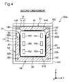
- Fig. 4 is a sectional view illustrating a fuel cell according to a second embodiment.
- a fuel cell 100a of the second embodiment differs from the fuel cell 100 of the first embodiment by having a second impact transmission member 17 in place of the three impact transmission members 10 that are joined with the first outer cover 161. Otherwise the configuration of the fuel cell 100a is similar to that of the fuel cell 100, so that its detailed description is omitted.
- the impact transmission member 10 of the first embodiment is called "first impact transmission member 10".
- Fig. 4 shows a cross section of the fuel cell 100a at a corresponding position to the 1-1 cross section shown in Fig. 1 .
- the fuel cell 100a includes the second impact transmission member 17.
- the second impact transmission member 17 includes an impact support film 15 and a dilatant fluid 16.
- the impact support film 15 is a cloth member and is arranged to continuously cover a first side face S10, a second side face S20 and a third side face S30 of the fuel cell 100a.
- the impact support film 15 is arranged to be adjacent to three impact protection members 20 that are respectively placed adjacent to the above three side faces S10, S20 and S30. These three impact protection members 20 are bonded to the impact support film 15.
- the impact support film 15 is formed from the same material as that of the bag body 11 of the first embodiment.
- the positions in the Z-axis direction of +Z-direction ends 21 of the impact support film 15 are approximately equal to the position in the Z-axis direction of a fourth side face S40 of single fuel cells 110.
- the ends 21 of the impact support film 15 are not in contact with the first outer cover 161 or the second outer cover 162. In other words, the ends 21 of the impact support film 15 are free ends. Openings 22 are accordingly formed between the ends 21 and the first outer cover 161. Ends in the X-axis direction (+X-direction end and -X-direction end) of the impact support film 15 are joined with the pair of terminal plates 120.
- the dilatant fluid 16 is placed in a space defined by the impact support film 15, the inner walls (side face S2, side face S3 and bottom face S4) of the first outer cover 161 and the pair of terminal plates 120.
- the entire bottom face S4, a vertically lower portion of the side face S2 and a vertically lower portion of the side face S3 of the first outer cover 161 are directly exposed to the dilatant fluid 16.
- the dilatant fluid 16 is made of the same material as that of the dilatant fluid 12 of the first embodiment. As shown in Fig. 4 , the positions in the Z-axis direction of upper ends S50 of the dilatant fluid 16 are located below (lower than) the positions in the Z-axis direction of the ends 21 (openings 22) of the impact support film 15.
- the first impact transmission member 10 is joined with the second outer cover 162, like the first embodiment.
- the fuel cell 100a of the second embodiment having the above configuration has similar advantageous effects to those of the fuel cell 100 of the first embodiment.
- the second impact transmission member 17 is readily formed by placing the impact support film 15 around the stacked body 101 joined with the impact protection members 20 and injecting the dilatant fluid 16 between the impact support film 15 and the first outer cover 161.
- the ends 21 are free ends, and the openings 22 are formed between the end 21 and the side face S2 and between the end 21 and the side face S3.
- this configuration suppresses the pressure of the dilatant fluid 16 from increasing to break off the second impact transmission member 17.
- the positions in the Z-axis direction (vertically upward positions) of the upper ends S50 of the dilatant fluid 16 are located below the positions in the Z-axis direction of the ends 21 (openings 22) of the impact support film 15. In the case where a large force is applied to the second impact transmission member 17, this configuration suppresses the dilatant fluid 16 from being ejected from the openings 22 beyond the ends 21.
- FIG. 5 is an exploded perspective view illustrating a fuel cell according to a third embodiment.
- a fuel cell 100b of the third embodiment differs from the fuel cell 100 of the first embodiment by having a second outer cover 162a in place of the second outer cover 162, having a third impact transmission member 10a and a fourth impact transmission member 17a in place of the four impact transmission members 10, and having four impact protection members 20a in place of the four impact protection members 20, but otherwise has similar configuration to that of the fuel cell 100.
- the second outer cover 162a differs from the second outer cover 162 of the first embodiment by a through hole 163 formed in the thickness direction (Z-axis direction) in its center portion. Otherwise the configuration of the second outer cover 162a is similar to that of the second outer cover 162, so that its detailed description is omitted.
- the third impact transmission member 10a includes a bag body 11a and a dilatant fluid 12a.
- the bag body 11a differs from the bag body 11 of the first embodiment by having a hemispherical outer shape.
- the other configuration and the material of the bag body 11a are similar to those of the bag body 11.
- the bag body 11a has a circular +Z-direction end that is joined with a center portion on a lower surface (surface facing the stacked body 101) of the second outer cover 162a.
- a space defined by the bag body 11a and the second outer cover 162a communicates with the through hole 163.
- the dilatant fluid 12a is placed in the space defined by the bag body 11a and the second outer cover 162a.
- the position in the Z-axis direction of an upper end of the dilatant fluid 12a is located below (lower than) the position in the Z-axis direction of an upper surface of the second outer cover 162a.
- the third impact transmission member 10a has a length in the X-axis direction that is shorter than the length in the X-axis direction of the stacked body 101.
- the dilatant fluid 12a is injected into the bag body 11a via the through hole 163 provided in the second outer cover 162a.
- the fourth impact transmission member 17a includes an impact support film 15a and a dilatant fluid 16a.
- the impact support film 15a is in an approximately U shape formed by bending a rectangular film along its short sides and deforming the rectangular film along the side face S2, the side face S3 and the bottom face S4.
- the respective sides other than +Z-direction ends of the impact support film 15a are respectively joined with the side face S2, the side face S3 and the bottom face S4.
- the +Z-direction ends of the impact support film 15a are not joined with the first outer cover 161 or the second outer cover 162.
- Openings 22a are accordingly formed at the +Z-direction ends of the fourth impact transmission member 17a.
- the positions in the Z-axis direction of the +Z-direction ends of the impact support film 15a are located below (lower than) the positions of the ends in the Z-axis direction of the first outer cover 161.
- the dilatant fluid 16a is placed in a space defined by the impact support film 15a and the side face S2, a space defined by the impact support film 15a and the side face S3 and a space defined by the impact support film 15a and the bottom face S4.
- the dilatant fluid 16a is made of the same material as that of the dilatant fluid 12 of the first embodiment. As shown in Fig. 5 , the positions in the Z-axis direction of upper ends of the dilatant fluid 16a are located below (lower than) the positions in the Z-axis direction of the openings 22a.
- the impact protection member 20a differs from the impact protection member 20 by having the length in the X-axis direction that is shorter than the length in the X-axis direction of the impact protection member 20 of the first embodiment, but otherwise has similar configuration to that of the impact protection member 20.
- the length in the X-axis direction of the impact protection member 20a is shorter than the length in the X-axis direction of the stacked body 101.
- the length in the X-axis direction of the impact protection member 20a may be, for example, equivalent to the total length (total thickness) in the X-axis direction of several to several tens of single fuel cells 110.
- Each impact protection member 20a is placed in a location corresponding to a middle portion in the X-axis direction of the stacked body 101. In other words, each impact protection member 20a is placed in a location corresponding to at least a center single fuel cell 110 of the stacked body 101 and several single fuel cells 110 adjacent to the center single fuel cell 110.
- the fuel cell 100b of the third embodiment having the above configuration has similar advantageous effects to those of the fuel cell 100 of the first embodiment. More specifically, the third impact transmission member 10a and the fourth impact transmission member 17a are placed in a location corresponding to the single fuel cells 110 in the middle portion that are more likely to have positional misalignment by application of a sudden impact. This configuration suppresses the positional misalignment of such single fuel cells 110.
- the lengths in the X-axis direction of the third impact transmission member 10a and the fourth impact transmission member 17a are shorter than the length in the X-axis direction of the stacked body 101.
- This configuration allows for downsizing of the third impact transmission member 10a and the fourth impact transmission member 17a, compared with the configuration that the lengths in the X-axis direction of the third impact transmission member 10a and the fourth impact transmission member 17a are equivalent to the length in the X-axis direction of the stacked body 101. This achieves weight reduction of the fuel cell 100b.
- Both the third impact transmission member 10a and the fourth impact transmission member 17a have the open +Z-direction ends.
- this configuration suppresses the pressure of the dilatant fluid 12a or the dilatant fluid 16a from increasing to break off the bag body 11a or the impact support film 15a.
- Fig. 6 is a sectional view illustrating a fuel cell according to a fourth embodiment.
- a fuel cell 100c of the fourth embodiment differs from the fuel cell 100 of the first embodiment by having twenty impact transmission members 10b in place of the four impact transmission members 10 and having four impact protection members 30 in place of the four impact transmission members 20. Otherwise the configuration of the fuel cell 100c is similar to that of the fuel cell 100, so that its detailed description is omitted.
- Fig. 7 is a perspective view illustrating the first outer cover 161 and the impact transmission members 10b in the fuel cell 100c according to the fourth embodiment.
- five impact transmission members 10b are joined with each of the inner side face S2, the inner side face S3 and the inner bottom face S4 of the first outer cover 161.
- five impact transmission members 10b are joined with the inner top face S1 of the second outer cover 162.
- each impact transmission member 10b has a columnar outer shape of semi-elliptical cross section and is extended along the X-axis direction.
- the respective impact transmission members 10b are arrayed and arranged at predetermined intervals in the Z-axis direction or in the Y-axis direction to be parallel to one another on the second outer cover 162 or the first outer cover 161.
- the impact transmission member 10b of the fourth embodiment includes a bag body 11b and a dilatant fluid 12b.
- the bag body 11b has a different outer shape from that of the bag body 11 of the first embodiment.
- the other configuration and the material of the bag body 11b are similar to those of the bag body 11.
- the bag body 11b has an opening that is closed by the second outer cover 162 or the first outer cover 161.
- the dilatant fluid 12b is placed in a space defined by each bag body 11b and the second outer cover 162 or the first outer cover 161.
- the dilatant fluid 12b is made of the same material as that of the dilatant fluid 12 of the first embodiment.
- the impact protection member 30 is a cloth member and is placed between the impact transmission member 10b and each side face of the stacked body 101 along the stacking direction SD.
- the impact protection member 30 differs from the impact transmission member 10 of the first embodiment by having a surface that is opposed to the impact transmission members 10b and is partly not in contact with the impact transmission members 10b.
- the other configuration and the material of the impact protection member 30 are similar to those of the impact transmission member 10.
- each impact protection member 30 opposed to the impact transmission members 10b is in contact with only the tops of the impact transmission members 10b (i.e., most distant portions of the impact transmission members 10b that are farthest toward the stacked body 101 from contact portions of the impact transmission members 10b in contact with the second cover 162 or the first cover 161), and the residual surface is not in contact with the impact transmission members 10b.
- the contact regions between the impact protection member 30 and the impact transmission members 10b are fully joined with each other, like the contact regions between the impact transmission member 10 and the impact protection member 20 of the first embodiment.
- the fuel cell 100c of the fourth embodiment having the above configuration has similar advantageous effects to those of the fuel cell 100 of the first embodiment. Additionally, each of the faces S10, S20, S30 and S40 of the stacked body 101 is supported by the plurality of impact transmission members 10b. This enhances the bearing power on each face.
- FIG. 8 is an exploded perspective view illustrating the configuration of a fuel cell according to a fifth embodiment.
- a fuel cell 100d of the fifth embodiment differs from the fuel cell 100 of the first embodiment by having fastening support manifolds that are formed inside of a stacked body 101a and the deformation absorbing member 102, having two fastening support members 41 and 42 in place of the four fastening support members 130, having two impact transmission members 10c in place of the four impact transmission members 10 and having two impact protection members 31 in place of the four impact protection members 20, but otherwise has similar configuration to that of the fuel cell 100.
- a single fuel cell 110a of the fifth embodiment differs from the single fuel cell 110 of the first embodiment by having two through holes 157 and 158 that are formed in the thickness direction, but otherwise has similar configuration to that of the single fuel cell 110.
- the stacked arrangement of the individual through holes 157 and 158 of the respective single fuel cells 100 in the stacking direction SD forms two manifolds (fastening support manifolds) along the stacking direction SD inside of the stacked body 101a.
- the two fastening support manifolds are omitted from the illustration of Fig. 8 .
- Two through holes (not shown) are also formed in the thickness direction in the deformation absorbing member 102. These two through holes are arranged at the corresponding positions to the through holes 157 and 158 of the respective single fuel cells 110a in the X-axis direction.
- the two fastening support members 41 and 42 differ from the fastening support members 130 of the first embodiment by being placed in the fastening support manifolds (not shown) and having a quadrangular prism outer shape, but otherwise have similar configuration to that of the fastening support members 130.
- the fastening support members 41 and 42 may be formed in a columnar outer shape like the outer shape of the fastening support members 130 of the first embodiment.
- Fig. 9 is a diagram illustrating a cross section of the fastening support manifold, the impact transmission member 10c, the fastening support member 41 and the impact protection member 31. Like Fig. 2 , Fig. 9 shows a cross section perpendicular to the stacking direction SD.
- the fastening support manifold 57 shown in Fig. 9 is formed by stacking the through holes 157 of the respective single fuel cells 110a shown in Fig. 8 .
- the impact transmission member 10c of the fifth embodiment is placed inside of the fastening support manifold 57.
- the impact transmission member 10c includes a bag body 11c and a dilatant fluid 12c.
- the bag body 11c has a tubular outer shape having its longitudinal direction identical with the X-axis direction and is configured to cover the fastening support member 41.
- the bag body 11c has two ends in the X-axis direction that are joined with the pair of terminal plates 120.
- the bag body 11c is formed from the same material as that of the bag body 11 of the first embodiment.
- the dilatant fluid 12c is placed in a space defined by the bag body 11c, the outer surface of the fastening support member 41 and the pair of terminal plates 120.
- the dilatant fluid 12c is made of the same material as that of the dilatant fluid 12 of the first embodiment.
- the impact protection member 31 has a similar shape to that of the bag body 11c and is placed inside of the fastening support manifold 57 to cover the bag body 11c.
- the impact protection member 31 is placed between the respective wall surfaces of the respective single fuel cells 110a forming the fastening support manifold 57 (through holes 157) (i.e., respective wall surfaces exposed on the through holes 157) and the impact transmission member 10c.
- the impact protection member 31 is formed from the same material as that of the impact protection member 20 of the first embodiment.
- the impact protection member 31 is joined with the above respective wall surfaces of the respective single fuel cells 110a forming the fastening support manifold 57 (through holes 157).
- the internal configuration of the fastening support manifold (not shown) formed by stacking the through holes 158 of the respective single fuel cells 110a is similar to the internal configuration of the fastening support manifold 57 described above and is thus not specifically described.
- the fuel cell 100d of the fifth embodiment having the above configuration has similar advantageous effects to those of the fuel cell 100 of the first embodiment. More specifically, in the case where a large inertial force is applied to the stacked body 101a in a short time period by a collision or the like, the dilatant fluid 12c behaves like a solid to transmit the inertial force to the fastening support members 41 and 42, while suppressing deformation or more specifically suppressing absorption of the inertial force.
- the fastening support members 41 and 42 then transmit a stress in the reverse direction to the inertial force to the impact transmission members 10c, and the impact transmission members 10c transmit the stress via the impact protection members 31 to the stacked body 101a.
- This configuration suppress positional misalignment of the respective single fuel cells 110a in the stacked body 101a.
- the dilatant fluid 12c behaves as a fluid and is deformed to fill a gap caused by the displacement of the single fuel cell 110a (gap between the wall surface forming the fastening support manifold and the impact protection member 31). This suppresses the occurrence of a gap between the wall surface forming the fastening support manifold and the impact protection member 31.
- fastening support members 41 and 42 of the fifth embodiment described above correspond to the fastening support member and the rod-like member in the claims.
- the bag body 11 of the first embodiment has an opening that is joined with the top face S1 of the second outer cover 162 or with the side face S2, the side face S3 and the bottom face S4 of the first outer cover 161.
- the invention is, however, not limited to this configuration.
- the opening of the bag body 11 may be joined with the surface of the stacked body 101 or with the impact protection member 20, in place of the first outer cover 161 and the second outer cover 162.
- a sealed bag body (without an opening) previously filled with the dilatant fluid 12 may be used as the impact transmission member 10.
- This impact transmission member 10 may be placed between the stacked body 101 (impact protection member 20) and the first outer cover 161 and between the stacked body 101 (impact protection member 20) and the second outer cover 162. In this modified configuration, the impact transmission member 10 may not be joined with the first outer cover 161 and may not be joined with the second outer cover 162.
- a configuration that the bag body 11 is filled with the dilatant fluid 12 with leaving some room i.e., the dilatant fluid 12 filled in the bag body 11 has the smaller volume than the internal capacity of the bag body 11
- the dilatant fluid 12 filled in the bag body 11 has the smaller volume than the internal capacity of the bag body 11
- the bag body 11 In the configuration that the bag body 11 is filled with the dilatant fluid 12 with leaving some room, forming the bag body 11 from a material having high permeability to the air but low permeability to the dilatant fluid 12 allows the air inside of the bag body 11 to be released outside in the case where a sudden external force is applied.
- the impact protection member using this bag body 11 has the similar functions and the similar advantageous effects to those of the impact protection member 20 of the first embodiment.
- Another modification may omit the first impact transmission member 10 from the fuel cell 100a of the second embodiment.
- Another modification may omit the impact protection members 20, 20a, 30 or 31 from the respective embodiments.
- the number of the impact transmission members 10b placed on each of the top face S1 of the second outer cover 162 and the side face S2, the side face S3 and the bottom face S4 of the first outer cover 161 is five.
- the number of the impact transmission members 10b is, however, not limited to five but may be any arbitrary number.
- the four fastening support members 130 of the first embodiment may be provided, in addition to the two fastening support members 41 and 42.
- the impact protection members 20 or 20a are configured to have the lower rigidity than the dilatant fluid 12 or 12a to 12d.
- the rigidity of the impact protection members 20 or 20a may alternatively be configured to have the higher rigidity than the dilatant fluid 12 or 12a to 12d.
- This modified configuration enables a force to be evenly applied to the stacked body 101 or 101a (force to be distributed) in the case where a stress is applied to the fuel cell 100 or 100a to 100d, while the impact protection members 20 or 20a serve to suppress the bag body 11 or 11a to 11d from being broken off
- Fig. 10 is a diagram illustrating the outer shape of impact transmission members 10d according to a modification.
- the impact transmission member 10b of the fourth embodiment has the columnar outer shape of the semi-elliptical cross section as shown in Fig. 7 .
- the invention is, however, not limited to this outer shape.
- the impact transmission member 10d has an approximately cone-like outer shape as shown in Fig. 10 and includes a leading edge that is in contact with the impact protection member 30 and an opening that is formed in its bottom to be joined with the top face S1 of the second outer cover 162 or with the side face S2, the side face S3 and the bottom face S4 of the first outer cover 161.
- Fig. 10 illustrates only the impact transmission members 10d and the surface joined with the impact transmission members 10d, while omitting the residual components.
- the impact transmission member 10d includes a bag body 11d and a dilatant fluid 12d.
- the bag body 11d is formed from the same material as that of the bag body 11 of the first embodiment.
- the dilatant fluid 12d is made of the same material as that of the dilatant fluid 12 of the first embodiment.
- the impact transmission member 10d of this outer shape have similar advantageous effects to those of the fuel cell 100c of the fourth embodiment.
- the impact transmission member may have any arbitrary outer shape to be joined with the top face S1 of the second cover 162 or with the side face S2, the side face S3 and the bottom face S4 of the first outer cover 161.
- the length of the impact transmission members 10 or 10a to 10d along the stacking direction SD may be changed adequately.
- the length of the impact transmission member 10 of the first embodiment, the length of the impact transmission member 10b of the fourth embodiment or the length of the impact transmission member 10c of the fifth embodiment along the stacking direction SD may be shorter than the length of the stacked body 101 or the stacked body 101a along the stacking direction SD.
- the length along the stacking direction SD of an area in which the impact transmission members 10d are arranged may be shorter than the length of the stacked body 101 along the stacking direction SD.
- the lengths along the stacking direction SD of the third impact transmission member 10a and the fourth impact transmission member 17a of the third embodiment may be approximately equal to the length of the stacked body 101 along the stacking direction SD.
- the dilatant fluid 12 or 12a to 12d is made of the material obtained by kneading and drying a mixture of silicone oil and boric acid with a small amount of a catalyst in a high temperature environment.
- the invention is, however, not limited to this material. Any "mixture of a fluid and a solid powder" may be used as the material of the dilatant fluid 12 or 12a to 12d.
- the fluid employed may be water, aside from the above "material obtained by kneading and drying a mixture of silicone oil and boric acid with a small amount of a catalyst in a high temperature environment".
- the solid powder employed may be silica, resin powder, sand or starch.
- the four faces S10 to S40 of the stacked body 101 or 101a along the stacking direction SD are entirely covered by the first outer cover 161 and the second outer cover 162.
- at least one face among these four faces may be partly covered by the first outer cover 161 or the second outer cover 162.
- placing the impact transmission member 10 or 10a to 10d in a location corresponding to the partly covered portion of this face covered by the first outer cover 161 or the second outer cover 162 suppresses positional misalignment of the respective single fuel cells 110 or 110a.
- the cross section of the stacked body 101 or 101a perpendicular to the stacking direction SD has a rectangular shape in the respective embodiments, but may have any arbitrary shape.
- the first outer cover 161 and the second outer cover 162 may have any outer shape to cover at least part of the side faces of the stacked body 101 or 101a along the stacking direction.
- the positions in the Z-axis direction of the ends 21 of the impact support film 15 are approximately equal to the position in the Z-axis direction of the fourth side face S40 of the single fuel cell 110.
- the invention is, however, not limited to this configuration.
- the positions in the Z-axis direction of the ends 21 of the impact support film 15 may be positions shifted in the -Z direction (i.e., vertically lower positions) from the position in the Z-axis direction of the fourth side face S40 of the single fuel cell 110.
- the impact support film 15 employed in the fuel cell of the invention may be a cloth member that is configured to continuously cover the first side face S10 of the stacked body 101, at least a vertically lower portion on the second side face S20 of the stacked body 101 and at least a vertically lower portion on the third side face S30 of the stacked body 101.
- the ends 21 of the impact support film 15 are free ends. According to a modification, each of the ends 21 may be joined with one of the first outer cover 161, the second outer cover 162 and the stacked body 101, such as not to form an opening. Similarly, in the third embodiment, each of the +Z-direction ends of the impact support film 15a may be joined with the first outer cover 161 or the second outer cover 162, such as not to form the opening 22a.
- the fuel cell 100 or 100a to 100d is mounted on the electric vehicle.
- the fuel cell may, however, be applied to any of various moving bodies such as a hybrid vehicle, a ship or a robot, instead of the electric vehicle.
- the fuel cell 100 or 100a may be used as a stationary power supply
- X-axis direction and Y-axis direction (+Y direction and -Y direction) are directions parallel to the horizontal plane; +Z direction indicates vertically upward direction; and -Z direction indicates vertically downward direction.
- the invention is, however, not limited to this orientation.
- the X-axis direction and the Y-axis direction may be directions parallel to a plane intersecting with the horizontal plane, and the Z-axis direction may be a direction shifted from the vertical direction.
- the first side face S10 and the fourth side face S40 of the fuel cell 100 or 100a to 100d may not be necessarily parallel to the horizontal plane.
- the second side face S20 and the third side face S30 of the fuel cell 100 or 100a to 100d may not be necessarily parallel to the vertical direction.
Landscapes
- Chemical & Material Sciences (AREA)
- Life Sciences & Earth Sciences (AREA)
- Engineering & Computer Science (AREA)
- Manufacturing & Machinery (AREA)
- Sustainable Development (AREA)
- Sustainable Energy (AREA)
- Chemical Kinetics & Catalysis (AREA)
- Electrochemistry (AREA)
- General Chemical & Material Sciences (AREA)
- Crystallography & Structural Chemistry (AREA)
- Fuel Cell (AREA)
Description
- The present invention relates to a fuel cell.
- In order to improve the vibration resistance and the impact resistance, a proposed configuration of a fuel cell includes an elastic material such as silicon or urethane rubber that is filled between a fuel cell stack and a tension plate extended along a stacking direction of a plurality of single fuel cells constituting the fuel cell stack (Patent Literature 1). Another proposed configuration of a fuel cell divides a fuel cell stack into multi-cell modules, each including a plurality of single fuel cells, and fixes an end cell of each of the multi-cell modules to a binding shaft placed along a stacking direction of the fuel cell stack, so as to distribute an impact load applied to the fuel cell stack (Patent Literature 2).
-
- PTL 1:
JP 2003-203670A - PTL 2:
JP 2005-183358A - In the fuel cell described in
Patent Literature 1, however, the elastic material has low rigidity and is readily deformed when an inertial force is applied to the fuel cell by an external impact or the like to press the fuel cell against the elastic material. This suppresses damage of the single fuel cells but is likely to cause positional misalignment of the respective single fuel cells. The positional misalignment between adjacent single fuel cells is likely to damage seal between the single fuel cells and cause leakage of a reactive gas or a cooling medium. This problem is not characteristic of the configuration that the elastic material is filled between the tension plate and the fuel cell stack but is commonly found in any configuration that the elastic material is filled between the fuel cell stack and an outer cover provided to cover the fuel cell stack, for example, a configuration that the elastic material is filled between the fuel cell stack and a casing provided to contain the fuel cell stack therein. In the case where a material having high rigidity is used to suppress positional misalignment caused by an external impact, however, this interferes with motion of the single fuel cell in the stacking direction due to a change in environment such as temperature or humidity. This makes it likely to apply a larger load than an expected fastening load to the stacked body and reduce the durability of the single fuel cells. - In the fuel cell described in Patent Literature 2, on the other hand, an insulating member needs to be placed, for example, between the end cell and the binding shaft, in order to provide insulation between the respective end cells of the plurality of multi-cell modules. This need increases the number of components and thereby increases the manufacturing cost of the fuel cell.
- With regard to prior art fuel cells, other needs include improvement of the manufacturing efficiency of the fuel cell, power saving and easy manufacture.
- In order to solve at least part of the above problems, the invention may be implemented by any of the following aspects.
-
- (1) According to one aspect of the invention, there is provided a fuel cell. The fuel cell comprises a stacked body that has a stacked configuration by stacking a plurality of single fuel cells; a fastening support member that is extended along a stacking direction of the plurality of single fuel cells and is configured to fasten the stacked body in the stacking direction; and an impact transmission member that is configured to include a dilatant fluid and is placed between the stacked body and the fastening support member to be arranged in a location corresponding to multiple consecutive single fuel cells along the stacking direction among the plurality of single fuel cells. In the fuel cell of this aspect, the impact transmission member including the dilatant fluid is placed between the stacked body and the fastening support member. In the case where a sudden force is applied to the stacked body by a collision or the like, this configuration causes this force to be transmitted to the fastening support member, while suppressing absorption of this force. This configuration also causes a stress received from the fastening support member to be transmitted to the stacked body, while suppressing absorption of the stress. This accordingly suppresses positional misalignment of the respective single fuel cells. Additionally, in the case where each single fuel cell is slowly displaced in the stacking direction or the like due to, for example, thermal expansion of the single fuel cell, the impact transmission member is deformed along with such displacement and thereby suppresses the occurrence of a gap caused by the displacement of the single fuel cell. In the case where an external force is applied, this configuration causes this force to be transmitted to the fastening support member, while suppressing absorption of this force. This configuration also causes a stress received from the fastening support member to be transmitted to the stacked body, while suppressing absorption of the stress. Additionally, this configuration does not interfere with displacement of the single fuel cell in the stacking direction caused by expansion or contraction. This accordingly suppresses application of an excessive stress to the single fuel cell and improves the durability of the single fuel cell.
- (2) In the fuel cell of the above aspect, the fastening support member may include an outer cover that is configured to cover at least part of a side face of the stacked body along the stacking direction. The fuel cell of this aspect causes a sudden force applied to the stacked body to be transmitted to the outer cover, while suppressing absorption of this force. The fuel cell of this aspect also causes a stress received from the outer cover to be transmitted to the stacked body, while suppressing absorption of this stress.
- (3) In the fuel cell of the above aspect, the stacked body may have a through hole that is extended along the stacking direction, and the fastening support member may have a rod-like member that is placed in the through hole. The fuel cell of this aspect causes a sudden force applied to the stacked body to be transmitted to the rod-like member, while suppressing absorption of this force. The fuel cell of this aspect also causes a stress received from the rod-like member to be transmitted to the stacked body, while suppressing absorption of this stress.
- (4) In the fuel cell of the above aspect, the impact transmission member may include a bag-like member in which the dilatant fluid is placed. The fuel cell of this aspect suppresses leakage of the dilatant fluid in the course of disassembly of the fuel cell for the purpose of maintenance or the like, thus improving the workability.
- (5) The fuel cell of the above aspect may further comprise an impact protection member that is placed between the impact transmission member and the stacked body. For example, in the case where a sudden force is applied to the stacked body, the fuel cell of this aspect suppresses the impact transmission member from being damaged by the corner of the single fuel cell.
- (6) In the fuel cell of the above aspect, the impact transmission member may be placed in a location corresponding to multiple single fuel cells constituting a middle portion of the stacked body along the stacking direction. In general, when the fuel cell is mounted, the stacked body is fastened by fixing an end of the stacked body in the stacking direction to a support member. In this state, the fastening force applied to the single fuel cells in a middle portion along the stacking direction among the plurality of single fuel cells constituting the stacked body is smaller than the fastening force applied to the single fuel cells in an end portion along the stacking direction. In the case where a sudden force is applied to the stacked body, the single fuel cells in the middle portion along the stacking direction are thus more likely to have positional misalignment. In the fuel cell of this aspect, however, the impact transmission member is placed in the location corresponding to the multiple single fuel cells constituting the middle portion of the stacked body along the stacking direction. This configuration suppresses positional misalignment of the single fuel cells that are more likely to have positional misalignment.
- The invention may be implemented by various aspects, for example, a method of manufacturing a fuel cell, a fuel cell system and a vehicle equipped with a fuel cell.
-
-
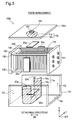
Fig. 1 is an exploded perspective view illustrating the configuration of a fuel cell according to a first embodiment of the invention; -
Fig. 2 is a sectional view illustrating the fuel cell according to the first embodiment; -
Fig. 3 is a diagram illustrating an inertial force applied tofuel cell 100 in the state that thefuel cell 100 is mounted on a vehicle; -
Fig. 4 is a sectional view illustrating a fuel cell according to a second embodiment; -
Fig. 5 is an exploded perspective view illustrating a fuel cell according to a third embodiment; -
Fig. 6 is a sectional view illustrating a fuel cell according to a fourth embodiment; -
Fig. 7 is a perspective view illustrating a firstouter cover 161 and impacttransmission members 10b in thefuel cell 100c according to the fourth embodiment; -
Fig. 8 is an exploded perspective view illustrating the configuration of a fuel cell according to a fifth embodiment; -
Fig. 9 is a diagram illustrating a cross section of a fastening support manifold, animpact transmission member 10c, afastening support member 41 and animpact protection member 31; and -
Fig. 10 is a diagram illustrating the outer shape ofimpact transmission members 10d according to a modification. -
Fig. 1 is an exploded perspective view illustrating the configuration of a fuel cell according to a first embodiment of the invention.Fig. 2 is a sectional view illustrating the fuel cell according to the first embodiment.Fig. 2 shows a cross section taken on a line 1-1 inFig. 1 . As shown inFig. 1 , afuel cell 100 includes astacked body 101, adeformation absorbing member 102, a pair of terminal plates 140, fourfastening support members 130, fourimpact protection members 20, a firstouter cover 161 and a secondouter cover 162. As shown inFig. 2 , thefuel cell 100 also includes fourimpact transmission members 10. Thefuel cell 100 is combined with, for example, supply systems of reactive gases (fuel gas and oxidizing gas) and a supply system of a cooling medium to constitute a fuel cell system. This fuel cell system may be mounted on an electric vehicle or the like to be used as a system of providing power supply for driving. - As shown in
Fig. 1 , thestacked body 101 has a stacked configuration of a plurality ofsingle fuel cells 110 along a stacking direction SD. The stacking direction SD of thesingle fuel cells 110 is parallel to X-axis direction (+X direction and -X direction). In the state that thefuel cell 100 is mounted, X-axis direction and Y-axis direction (+Y direction and -Y direction) are directions parallel to the horizontal plane; +Z direction indicates vertically upward direction; and -Z direction indicates vertically downward direction. - According to this embodiment, the
single fuel cell 110 is a polymer electrolyte fuel cell. Thesingle fuel cell 110 has an approximately cubic outer shape. As shown inFig. 2 , thesingle fuel cell 110 has a first side face S10 that forms a bottom face in the state that thefuel cell 100 is mounted, a second side face S20 that is arranged adjacent to the first side face S10, a third side face S30 that is arranged adjacent to the first side face S10 and is opposed to the second side face S20, and a fourth side face S40 that forms a top face and is opposed to the first side face S10. All these four side faces S10, S20, S30 and S40 are side faces along the stacking direction SD. This term "along the stacking direction SD" is used in a wide sense including a direction that crosses the stacking direction SD other than a direction perpendicular to the stacking direction SD, in addition to a direction parallel to the stacking direction SD. - As shown in
Fig. 1 , thesingle fuel cell 110 includes amembrane electrode assembly 111 and a pair ofseparators membrane electrode assembly 111 therebetween. Themembrane electrode assembly 111 includes an electrolyte membrane, two catalyst layers provided on respective surfaces of the electrolyte membrane, and two gas diffusion layers provided to place the electrolyte membrane and the two catalyst layers therebetween. According to this embodiment, the electrolyte membrane is a sulfonate group-containing fluororesin-based ion exchange membrane. The electrolyte membrane is, however, not limited to the sulfonate group-containing membrane but may be another ion exchange group-containing membrane such as phosphate group-containing membrane or carboxylate group-containing membrane. The catalyst layer is formed from a base material (catalyst carrier) in which a catalyst such as platinum or a platinum alloy is supported on a conductive carrier (for example, carbon particles). The gas diffusion layer is formed from a porous material. The porous material may be, for example, a carbon porous material such as carbon paper or a metal porous material such as metal mesh or foamed metal. The separator is formed from a gas-impermeable conductive material. Available examples of such material include dense carbon formed by compression of carbon to be gas impermeable and a press-molded metal plate. - Flow passages of reactive gases and a flow passage of a cooling medium are formed along the stacking direction SD in the
single fuel cell 110. More specifically, as shown inFig. 1 , thesingle fuel cell 110 includes an oxidizinggas supply passage 151, an oxidizinggas exhaust passage 152, a fuelgas supply passage 153, a fuelgas exhaust passage 154, a coolingmedium supply passage 155 and a coolingmedium discharge passage 156. The stacked arrangement of the individual flow passages of the respectivesingle fuel cells 110 in the stacking direction SD forms an oxidizing gas supply manifold, an oxidizing gas exhaust manifold, a fuel gas supply manifold, a fuel gas exhaust manifold, a cooling medium supply manifold and a cooling medium discharge manifold (not shown) in thestacked body 101. - The
deformation absorbing member 102 is provided outside of an end cell (outermost single fuel cell 110) on one side of thestacked body 101 to be placed between this end cell and theterminal plate 120. Thedeformation absorbing member 102 is made of an elastomer such as rubber and serves to absorb deformation of thestacked body 101 in the stacking direction SD caused by thermal expansion of thesingle fuel cells 110. Thedeformation absorbing member 102 may be formed from any elastic body such as spring, instead of the elastomer. - With regard to the pair of
terminal plates 120, oneterminal plate 120 is placed outside of thedeformation absorbing member 102 to be adjacent to thedeformation absorbing member 102, while the otherterminal plate 120 is placed outside of an end cell on a side without thedeformation absorbing member 102 to be adjacent to this end cell. The respectiveterminal plates 120 serve to collect the electric current generated in thestacked body 101. The pair ofterminal plates 120 serve to apply a predetermined fastening force in the stacking direction SD to a stacked assembly including the stackedbody 101 and thedeformation absorbing member 102. Theterminal plate 120 that is not adjacent to thedeformation absorbing member 102 has six connection ports 121 that are connected with the respective manifolds formed in thestacked body 101. Planes of eachterminal plate 120 perpendicular to the stacking direction SD are formed in a rectangular shape. - The four
fastening support members 130 are rod-like members and are arranged between the pair ofterminal plates 120 along the stacking direction SD. As shown inFig. 2 , eachfastening support member 130 is arranged to connect its corners at corresponding positions of the twoterminal plates 120 with each other. The respectivefastening support members 130 are connected with both theterminal plates 120 to maintain the fastening force in the stacking direction SD applied to the stacked assembly including the stackedbody 101 and thedeformation absorbing member 102. - As shown in
Fig. 1 , theimpact transmission member 10 has an outer shape having its longitudinal direction identical with the stacking direction SD. As shown inFig. 2 , theimpact transmission member 10 includes abag body 11 and a dilatant fluid 12 filled inside of thebag body 11. For convenience of illustration, thedilatant fluid 12 is omitted from the illustration ofFig. 1 . As shown inFig. 1 , thebag body 11 has a thin bag-like outer shape with an opening and includes amain wall portion 19 and a pair ofside wall portions 18. Themain wall portion 19 is arranged to face one of the four side faces S10, S20, S30 and S40 of thestacked body 101 ad to be adjacent to theimpact protection member 20. Themain wall portion 19 has a +X-direction edge connected with oneside wall portion 18 and a -X-direction edge connected with the otherside wall portion 18. The pair ofside wall portions 18 are arranged to be adjacent to the respectiveterminal plates 120. Thebag body 11 is made of a material having low permeability of thedilatant fluid 12. More specifically, thebag body 11 is made of polypropylene according to this embodiment. Another resin or an elastomer such as urethane may be used in place of polypropylene. - An
edge portion 190 that forms an opening of eachimpact transmission member 10 as shown inFig. 1 is joined with an inner surface of the secondouter cover 162 or an inner surface of the firstouter cover 161 as shown inFig. 2 . In other words, the opening of eachimpact transmission member 10 is closed by the firstouter cover 161 or by the secondouter cover 162. More specifically, as shown inFig. 2 , an inner top face S1 of the secondouter cover 162, two inner side faces S2 and S3 along the vertical direction of the firstouter cover 161 and an inner bottom face S4 of the firstouter cover 161 are respectively joined with theedge portions 190 of thebag bodies 11. According to this embodiment, a bonding method using an adhesive is employed to join theedge portion 190 with the inner surface of the secondouter cover 162 or the inner surface of the firstouter cover 161. The bonding method using the adhesive may be replaced by any other joining method such as welding or simple insertion. - The
dilatant fluid 12 behaves like a solid in response to an abrupt change and shows fluidity in response to a slow deformation. According to this embodiment, thedilatant fluid 12 is made of a material obtained by kneading and drying a mixture of silicone oil and boric acid with a small amount of a catalyst (for example, iron chloride or nickel chloride) in a high temperature environment (for example, temperature of not lower than 100 degrees Celsius). Available examples of such material include Dow Corning 3179 ("Dow Corning" is registered trademark) manufactured by Dow Corning Corporation and M48 and M49 manufactured by Wacker GmbH. - As described above, the opening of each
bag body 11 is closed by the firstouter cover 161 or the secondouter cover 162, so as to prevent leakage of the dilatant fluid 12 from thebag body 11. - The
impact protection member 20 is a thin flexible cloth member and has a rectangular outer shape having its longitudinal direction identical with the stacking direction SD. According to this embodiment, theimpact protection member 20 is formed from Kevlar (registered trademark). Theimpact protection member 20 may be formed from any other material, such as glass fiber, having the higher rigidity than that of thebag body 11, in place of Kevlar. Theimpact protection member 20 may alternatively be formed from a material having the lower rigidity than that of thebag body 11. According to this embodiment, theimpact protection member 20 has the lower rigidity than that of thedilatant fluid 12. The rigidity of thedilatant fluid 12 to be compared with the rigidity of theimpact protection member 20 herein means the rigidity measured by application of a sudden impact to theimpact transmission member 10. - The
impact protection member 20 is placed between theimpact transmission member 10 and each side face along the stacking direction SD of thestacked body 101. More specifically, oneimpact protection member 20 is placed between the first side face S10 of thestacked body 101 and theimpact transmission member 10 joined with the bottom face S4 of the firstouter cover 161. Oneimpact protection member 20 is placed between the second side face S20 of thestacked body 101 and theimpact transmission member 10 joined with the side face S2 of the firstouter cover 161. Oneimpact protection member 20 is placed between the third side face S30 of thestacked body 101 and theimpact transmission member 10 joined with the side face S3 of the firstouter cover 161. Oneimpact protection member 20 is placed between the fourth side face S40 of thestacked body 101 and theimpact transmission member 10 joined with the secondouter cover 162. According to this embodiment, the contact areas of eachimpact transmission member 10 and the correspondingimpact protection member 20 are entirely bonded to each other. The contact areas of eachimpact transmission member 10 and the correspondingimpact protection member 20 may be only partly bonded to each other. Such contact areas may not be bonded to each other. Theimpact protection member 20 serves to protect thebag body 11 from an impact. For example, theimpact protection member 20 suppresses thebag body 11 from being damaged by the corner of thesingle fuel cell 110 when a sudden force is applied to thefuel cell 100. - As shown in
Figs. 1 and2 , the firstouter cover 161 is formed in an outer shape of an approximately U-shaped cross section viewed in the X-axis direction. The length in the X-axis direction of the firstouter cover 161 is approximately equal to the length in the X-axis direction of an assembly including the stackedbody 101, thedeformation absorbing member 102 and the pair ofterminal plates 120. The firstouter cover 161 is configured to cover theentire fuel cell 100 except the firstouter cover 161 and the secondouter cover 162 upward (in the +Z direction) and sideways (in the +Y direction and -Y direction). The secondouter cover 162 is a plate-like member having its thickness direction identical with the Z-axis direction and is arrange to cover the upper opening of the firstouter cover 161. - The first
outer cover 161 and the secondouter cover 162 described above correspond to the fastening support member and the outer cover in the claims. Thebag body 11 corresponds to the bag-like member in the claims. -
Fig. 3 is a diagram illustrating an inertial force applied to thefuel cell 100 in the state that thefuel cell 100 is mounted on a vehicle. As shown inFig. 3 , the firstouter cover 161 is fixed to aside member 500 of the vehicle. For example, in the case of a head-on collision of the vehicle in this state, an inertial force Fg in a traveling direction is applied to thestacked body 101 that is not directly connected with theside member 500. The respectivesingle fuel cells 110 constituting thestacked body 101 are likely to be shifted in the traveling direction. Especially thesingle fuel cells 110 located in a middle portion in the stacking direction SD (X-axis direction) of thesingle fuel cells 110 receive only a weak fastening force applied by the pair ofterminal plates 120 and are thus likely to be shifted significantly. Theimpact transmission member 10 is provided on a traveling direction side of thestacked body 101. Thedilatant fluid 12 of theimpact transmission member 10 behaves like a solid in response to an abrupt change. Accordingly thedilatant fluid 12 transmits the inertial force Fg to the firstouter cover 161, while suppressing deformation or more specifically suppressing absorption of the inertial force Fg. The firstouter cover 161 then transmits a stress FB in the reverse direction to the inertial force Fg to theimpact transmission member 10, and theimpact transmission member 10 transmits the stress FB via theimpact protection member 20 to thestacked body 101. This results in suppressing positional misalignment of the respectivesingle fuel cells 110 in thestacked body 101. - In the case where each
single fuel cell 110 is slowly displaced in the stacking direction SD due to, for example, thermal expansion of thesingle fuel cell 110, unlike the case of the collision described above, thedilatant fluid 12 behaves as a fluid and is deformed to fill a gap caused by the displacement of the single fuel cell 110 (gap between thesingle fuel cell 110 and the impact protection member 20). This suppresses the occurrence of a gap between thesingle fuel cell 110 and theimpact protection member 20. In the case of a collision, this accordingly causes the inertial force Fg to be transmitted via theimpact transmission member 10 to the firstouter cover 161, while suppressing positional misalignment of thesingle fuel cell 110. - In the
fuel cell 100 of the first embodiment described above, theimpact transmission member 10 including thedilatant fluid 12 is placed between thestacked body 101 and the firstouter cover 161 or the secondouter cover 162. In the case where a sudden force is applied to thestacked body 101 by a collision or the like, this configuration transmits this force to the firstouter cover 161 or the secondouter cover 162, while suppressing absorption of this force. This configuration also transmits a stress resulting from this force to thestacked body 101, while suppressing absorption of the stress. This results in suppressing positional misalignment of the respectivesingle fuel cells 110 and thereby suppresses leakage of the reactive gas or the cooling medium due to the positional misalignment of thesingle fuel cells 110. - Additionally, in the case where each
single fuel cell 110 is slowly displaced due to, for example, thermal expansion of thesingle fuel cell 110, theimpact transmission member 10 is deformed along with such displacement. This configuration does not interfere with displacement of thesingle fuel cell 110. This accordingly suppresses application of an excessive stress to thesingle fuel cell 110 and improves the durability of thesingle fuel cell 110. Theimpact transmission member 10 is deformed along with such displacement of thesingle fuel cell 110. This suppresses the occurrence of a gap caused by the displacement of thesingle fuel cell 110. Accordingly this configuration more stably suppresses positional misalignment of the respectivesingle fuel cells 110 in the case where a sudden force is applied to thestacked body 101. - The
impact transmission member 10 has an elongated shape having its longitudinal direction identical with the stacking direction SD, so that thedilatant fluid 12 is placed in a location corresponding to a large number of thesingle fuel cells 110 out of therespective fuel cells 100 of thestacked body 101. This configuration suppresses positional misalignment of the large number of thesingle fuel cells 110. - The
impact transmission member 10 is configured such that the opening of thebag body 11 is closed by the firstouter cover 161 or the secondouter cover 162 and that thedilatant fluid 12 is placed in thebag body 11. This configuration suppresses leakage of thedilatant fluid 12 in the course of detachment of the firstouter cover 161 or the secondouter cover 162, thus improving the workability. - The
impact protection member 20 is placed between theimpact transmission member 10 and thestacked body 101. This suppresses thebag body 11 from being damaged by the corner of thesingle fuel cell 110 in the case where a sudden force is applied to thefuel cell 100. -
Fig. 4 is a sectional view illustrating a fuel cell according to a second embodiment. Afuel cell 100a of the second embodiment differs from thefuel cell 100 of the first embodiment by having a secondimpact transmission member 17 in place of the threeimpact transmission members 10 that are joined with the firstouter cover 161. Otherwise the configuration of thefuel cell 100a is similar to that of thefuel cell 100, so that its detailed description is omitted. In the second embodiment, theimpact transmission member 10 of the first embodiment is called "firstimpact transmission member 10". -
Fig. 4 shows a cross section of thefuel cell 100a at a corresponding position to the 1-1 cross section shown inFig. 1 . As shown inFig. 4 , thefuel cell 100a includes the secondimpact transmission member 17. The secondimpact transmission member 17 includes an impact support film 15 and adilatant fluid 16. - The impact support film 15 is a cloth member and is arranged to continuously cover a first side face S10, a second side face S20 and a third side face S30 of the
fuel cell 100a. The impact support film 15 is arranged to be adjacent to threeimpact protection members 20 that are respectively placed adjacent to the above three side faces S10, S20 and S30. These threeimpact protection members 20 are bonded to the impact support film 15. The impact support film 15 is formed from the same material as that of thebag body 11 of the first embodiment. The positions in the Z-axis direction of +Z-direction ends 21 of the impact support film 15 are approximately equal to the position in the Z-axis direction of a fourth side face S40 ofsingle fuel cells 110. The ends 21 of the impact support film 15 are not in contact with the firstouter cover 161 or the secondouter cover 162. In other words, the ends 21 of the impact support film 15 are free ends.Openings 22 are accordingly formed between theends 21 and the firstouter cover 161. Ends in the X-axis direction (+X-direction end and -X-direction end) of the impact support film 15 are joined with the pair ofterminal plates 120. - In the second embodiment, the
dilatant fluid 16 is placed in a space defined by the impact support film 15, the inner walls (side face S2, side face S3 and bottom face S4) of the firstouter cover 161 and the pair ofterminal plates 120. The entire bottom face S4, a vertically lower portion of the side face S2 and a vertically lower portion of the side face S3 of the firstouter cover 161 are directly exposed to thedilatant fluid 16. Thedilatant fluid 16 is made of the same material as that of thedilatant fluid 12 of the first embodiment. As shown inFig. 4 , the positions in the Z-axis direction of upper ends S50 of thedilatant fluid 16 are located below (lower than) the positions in the Z-axis direction of the ends 21 (openings 22) of the impact support film 15. - The first
impact transmission member 10 is joined with the secondouter cover 162, like the first embodiment. - The
fuel cell 100a of the second embodiment having the above configuration has similar advantageous effects to those of thefuel cell 100 of the first embodiment. Additionally, the secondimpact transmission member 17 is readily formed by placing the impact support film 15 around thestacked body 101 joined with theimpact protection members 20 and injecting thedilatant fluid 16 between the impact support film 15 and the firstouter cover 161. The ends 21 are free ends, and theopenings 22 are formed between theend 21 and the side face S2 and between theend 21 and the side face S3. In the case where a large force is applied to the secondimpact transmission member 17, this configuration suppresses the pressure of the dilatant fluid 16 from increasing to break off the secondimpact transmission member 17. The positions in the Z-axis direction (vertically upward positions) of the upper ends S50 of thedilatant fluid 16 are located below the positions in the Z-axis direction of the ends 21 (openings 22) of the impact support film 15. In the case where a large force is applied to the secondimpact transmission member 17, this configuration suppresses the dilatant fluid 16 from being ejected from theopenings 22 beyond the ends 21. -
Fig. 5 is an exploded perspective view illustrating a fuel cell according to a third embodiment. Afuel cell 100b of the third embodiment differs from thefuel cell 100 of the first embodiment by having a secondouter cover 162a in place of the secondouter cover 162, having a third impact transmission member 10a and a fourthimpact transmission member 17a in place of the fourimpact transmission members 10, and having fourimpact protection members 20a in place of the fourimpact protection members 20, but otherwise has similar configuration to that of thefuel cell 100. - The second
outer cover 162a differs from the secondouter cover 162 of the first embodiment by a throughhole 163 formed in the thickness direction (Z-axis direction) in its center portion. Otherwise the configuration of the secondouter cover 162a is similar to that of the secondouter cover 162, so that its detailed description is omitted. - The third impact transmission member 10a includes a
bag body 11a and a dilatant fluid 12a. Thebag body 11a differs from thebag body 11 of the first embodiment by having a hemispherical outer shape. The other configuration and the material of thebag body 11a are similar to those of thebag body 11. Thebag body 11a has a circular +Z-direction end that is joined with a center portion on a lower surface (surface facing the stacked body 101) of the secondouter cover 162a. A space defined by thebag body 11a and the secondouter cover 162a communicates with the throughhole 163. The dilatant fluid 12a is placed in the space defined by thebag body 11a and the secondouter cover 162a. The position in the Z-axis direction of an upper end of the dilatant fluid 12a is located below (lower than) the position in the Z-axis direction of an upper surface of the secondouter cover 162a. The third impact transmission member 10a has a length in the X-axis direction that is shorter than the length in the X-axis direction of thestacked body 101. The dilatant fluid 12a is injected into thebag body 11a via the throughhole 163 provided in the secondouter cover 162a. - The fourth
impact transmission member 17a includes animpact support film 15a and adilatant fluid 16a. Theimpact support film 15a is in an approximately U shape formed by bending a rectangular film along its short sides and deforming the rectangular film along the side face S2, the side face S3 and the bottom face S4. The respective sides other than +Z-direction ends of theimpact support film 15a are respectively joined with the side face S2, the side face S3 and the bottom face S4. The +Z-direction ends of theimpact support film 15a are not joined with the firstouter cover 161 or the secondouter cover 162.Openings 22a are accordingly formed at the +Z-direction ends of the fourthimpact transmission member 17a. The positions in the Z-axis direction of the +Z-direction ends of theimpact support film 15a are located below (lower than) the positions of the ends in the Z-axis direction of the firstouter cover 161. - The
dilatant fluid 16a is placed in a space defined by theimpact support film 15a and the side face S2, a space defined by theimpact support film 15a and the side face S3 and a space defined by theimpact support film 15a and the bottom face S4. Thedilatant fluid 16a is made of the same material as that of thedilatant fluid 12 of the first embodiment. As shown inFig. 5 , the positions in the Z-axis direction of upper ends of thedilatant fluid 16a are located below (lower than) the positions in the Z-axis direction of theopenings 22a. - The
impact protection member 20a differs from theimpact protection member 20 by having the length in the X-axis direction that is shorter than the length in the X-axis direction of theimpact protection member 20 of the first embodiment, but otherwise has similar configuration to that of theimpact protection member 20. The length in the X-axis direction of theimpact protection member 20a is shorter than the length in the X-axis direction of thestacked body 101. The length in the X-axis direction of theimpact protection member 20a may be, for example, equivalent to the total length (total thickness) in the X-axis direction of several to several tens ofsingle fuel cells 110. Eachimpact protection member 20a is placed in a location corresponding to a middle portion in the X-axis direction of thestacked body 101. In other words, eachimpact protection member 20a is placed in a location corresponding to at least a centersingle fuel cell 110 of thestacked body 101 and severalsingle fuel cells 110 adjacent to the centersingle fuel cell 110. - The
fuel cell 100b of the third embodiment having the above configuration has similar advantageous effects to those of thefuel cell 100 of the first embodiment. More specifically, the third impact transmission member 10a and the fourthimpact transmission member 17a are placed in a location corresponding to thesingle fuel cells 110 in the middle portion that are more likely to have positional misalignment by application of a sudden impact. This configuration suppresses the positional misalignment of suchsingle fuel cells 110. - The lengths in the X-axis direction of the third impact transmission member 10a and the fourth
impact transmission member 17a are shorter than the length in the X-axis direction of thestacked body 101. This configuration allows for downsizing of the third impact transmission member 10a and the fourthimpact transmission member 17a, compared with the configuration that the lengths in the X-axis direction of the third impact transmission member 10a and the fourthimpact transmission member 17a are equivalent to the length in the X-axis direction of thestacked body 101. This achieves weight reduction of thefuel cell 100b. Both the third impact transmission member 10a and the fourthimpact transmission member 17a have the open +Z-direction ends. Like the configuration of the second embodiment described above, in the case where a large force is applied to the third impact transmission member 10a or the fourthimpact transmission member 17a, this configuration suppresses the pressure of the dilatant fluid 12a or thedilatant fluid 16a from increasing to break off thebag body 11a or theimpact support film 15a. -
Fig. 6 is a sectional view illustrating a fuel cell according to a fourth embodiment. Afuel cell 100c of the fourth embodiment differs from thefuel cell 100 of the first embodiment by having twentyimpact transmission members 10b in place of the fourimpact transmission members 10 and having fourimpact protection members 30 in place of the fourimpact transmission members 20. Otherwise the configuration of thefuel cell 100c is similar to that of thefuel cell 100, so that its detailed description is omitted. -
Fig. 7 is a perspective view illustrating the firstouter cover 161 and theimpact transmission members 10b in thefuel cell 100c according to the fourth embodiment. As shown inFigs. 6 and7 , fiveimpact transmission members 10b are joined with each of the inner side face S2, the inner side face S3 and the inner bottom face S4 of the firstouter cover 161. As shown inFig. 6 , fiveimpact transmission members 10b are joined with the inner top face S1 of the secondouter cover 162. As shown inFigs. 6 and7 , eachimpact transmission member 10b has a columnar outer shape of semi-elliptical cross section and is extended along the X-axis direction. The respectiveimpact transmission members 10b are arrayed and arranged at predetermined intervals in the Z-axis direction or in the Y-axis direction to be parallel to one another on the secondouter cover 162 or the firstouter cover 161. - As shown in
Figs. 6 and7 , theimpact transmission member 10b of the fourth embodiment includes abag body 11b and adilatant fluid 12b. Thebag body 11b has a different outer shape from that of thebag body 11 of the first embodiment. The other configuration and the material of thebag body 11b are similar to those of thebag body 11. Thebag body 11b has an opening that is closed by the secondouter cover 162 or the firstouter cover 161. - The
dilatant fluid 12b is placed in a space defined by eachbag body 11b and the secondouter cover 162 or the firstouter cover 161. Thedilatant fluid 12b is made of the same material as that of thedilatant fluid 12 of the first embodiment. - The
impact protection member 30 is a cloth member and is placed between theimpact transmission member 10b and each side face of thestacked body 101 along the stacking direction SD. Theimpact protection member 30 differs from theimpact transmission member 10 of the first embodiment by having a surface that is opposed to theimpact transmission members 10b and is partly not in contact with theimpact transmission members 10b. The other configuration and the material of theimpact protection member 30 are similar to those of theimpact transmission member 10. The surface of eachimpact protection member 30 opposed to theimpact transmission members 10b is in contact with only the tops of theimpact transmission members 10b (i.e., most distant portions of theimpact transmission members 10b that are farthest toward thestacked body 101 from contact portions of theimpact transmission members 10b in contact with thesecond cover 162 or the first cover 161), and the residual surface is not in contact with theimpact transmission members 10b. The contact regions between theimpact protection member 30 and theimpact transmission members 10b are fully joined with each other, like the contact regions between theimpact transmission member 10 and theimpact protection member 20 of the first embodiment. - The
fuel cell 100c of the fourth embodiment having the above configuration has similar advantageous effects to those of thefuel cell 100 of the first embodiment. Additionally, each of the faces S10, S20, S30 and S40 of thestacked body 101 is supported by the plurality ofimpact transmission members 10b. This enhances the bearing power on each face. -
Fig. 8 is an exploded perspective view illustrating the configuration of a fuel cell according to a fifth embodiment. Afuel cell 100d of the fifth embodiment differs from thefuel cell 100 of the first embodiment by having fastening support manifolds that are formed inside of astacked body 101a and thedeformation absorbing member 102, having twofastening support members fastening support members 130, having twoimpact transmission members 10c in place of the fourimpact transmission members 10 and having twoimpact protection members 31 in place of the fourimpact protection members 20, but otherwise has similar configuration to that of thefuel cell 100. - As shown in
Fig. 8 , asingle fuel cell 110a of the fifth embodiment differs from thesingle fuel cell 110 of the first embodiment by having two throughholes single fuel cell 110. The stacked arrangement of the individual throughholes single fuel cells 100 in the stacking direction SD forms two manifolds (fastening support manifolds) along the stacking direction SD inside of thestacked body 101a. For convenience of illustration, the two fastening support manifolds are omitted from the illustration ofFig. 8 . Two through holes (not shown) are also formed in the thickness direction in thedeformation absorbing member 102. These two through holes are arranged at the corresponding positions to the throughholes single fuel cells 110a in the X-axis direction. - The two
fastening support members fastening support members 130 of the first embodiment by being placed in the fastening support manifolds (not shown) and having a quadrangular prism outer shape, but otherwise have similar configuration to that of thefastening support members 130. Thefastening support members fastening support members 130 of the first embodiment. -
Fig. 9 is a diagram illustrating a cross section of the fastening support manifold, theimpact transmission member 10c, thefastening support member 41 and theimpact protection member 31. LikeFig. 2 ,Fig. 9 shows a cross section perpendicular to the stacking direction SD. - The
fastening support manifold 57 shown inFig. 9 is formed by stacking the throughholes 157 of the respectivesingle fuel cells 110a shown inFig. 8 . As shown inFig. 9 , theimpact transmission member 10c of the fifth embodiment is placed inside of thefastening support manifold 57. Theimpact transmission member 10c includes abag body 11c and adilatant fluid 12c. Thebag body 11c has a tubular outer shape having its longitudinal direction identical with the X-axis direction and is configured to cover thefastening support member 41. Thebag body 11c has two ends in the X-axis direction that are joined with the pair ofterminal plates 120. Thebag body 11c is formed from the same material as that of thebag body 11 of the first embodiment. - The
dilatant fluid 12c is placed in a space defined by thebag body 11c, the outer surface of thefastening support member 41 and the pair ofterminal plates 120. Thedilatant fluid 12c is made of the same material as that of thedilatant fluid 12 of the first embodiment. - The
impact protection member 31 has a similar shape to that of thebag body 11c and is placed inside of thefastening support manifold 57 to cover thebag body 11c. Theimpact protection member 31 is placed between the respective wall surfaces of the respectivesingle fuel cells 110a forming the fastening support manifold 57 (through holes 157) (i.e., respective wall surfaces exposed on the through holes 157) and theimpact transmission member 10c. Theimpact protection member 31 is formed from the same material as that of theimpact protection member 20 of the first embodiment. Theimpact protection member 31 is joined with the above respective wall surfaces of the respectivesingle fuel cells 110a forming the fastening support manifold 57 (through holes 157). The internal configuration of the fastening support manifold (not shown) formed by stacking the throughholes 158 of the respectivesingle fuel cells 110a is similar to the internal configuration of thefastening support manifold 57 described above and is thus not specifically described. - The
fuel cell 100d of the fifth embodiment having the above configuration has similar advantageous effects to those of thefuel cell 100 of the first embodiment. More specifically, in the case where a large inertial force is applied to thestacked body 101a in a short time period by a collision or the like, thedilatant fluid 12c behaves like a solid to transmit the inertial force to thefastening support members fastening support members impact transmission members 10c, and theimpact transmission members 10c transmit the stress via theimpact protection members 31 to thestacked body 101a. This configuration suppress positional misalignment of the respectivesingle fuel cells 110a in thestacked body 101a. In the case where eachsingle fuel cell 110a is slowly displaced in the stacking direction SD due to, for example, thermal expansion of thesingle fuel cell 110a, thedilatant fluid 12c behaves as a fluid and is deformed to fill a gap caused by the displacement of thesingle fuel cell 110a (gap between the wall surface forming the fastening support manifold and the impact protection member 31). This suppresses the occurrence of a gap between the wall surface forming the fastening support manifold and theimpact protection member 31. In the case of a collision, this accordingly causes the inertial force to be transmitted via theimpact transmission members 10c to thefastening support members single fuel cell 110a. Additionally, this configuration does not interfere with displacement of thesingle fuel cell 110a in the stacking direction SD caused by expansion or contraction. This accordingly suppresses application of an excessive stress to thesingle fuel cell 110a and improves the durability of thesingle fuel cell 110a. - The
fastening support members - The configurations of the
fuel cells bag body 11 of the first embodiment has an opening that is joined with the top face S1 of the secondouter cover 162 or with the side face S2, the side face S3 and the bottom face S4 of the firstouter cover 161. The invention is, however, not limited to this configuration. According to a modification, the opening of thebag body 11 may be joined with the surface of thestacked body 101 or with theimpact protection member 20, in place of the firstouter cover 161 and the secondouter cover 162. According to another modification, a sealed bag body (without an opening) previously filled with thedilatant fluid 12 may be used as theimpact transmission member 10. Thisimpact transmission member 10 may be placed between the stacked body 101 (impact protection member 20) and the firstouter cover 161 and between the stacked body 101 (impact protection member 20) and the secondouter cover 162. In this modified configuration, theimpact transmission member 10 may not be joined with the firstouter cover 161 and may not be joined with the secondouter cover 162. In this modified configuration, a configuration that thebag body 11 is filled with the dilatant fluid 12 with leaving some room (i.e., thedilatant fluid 12 filled in thebag body 11 has the smaller volume than the internal capacity of the bag body 11) may be employed, in addition to the configuration that thebag body 11 is filled with thedilatant fluid 12 without leaving any room. In the configuration that thebag body 11 is filled with the dilatant fluid 12 with leaving some room, forming thebag body 11 from a material having high permeability to the air but low permeability to thedilatant fluid 12 allows the air inside of thebag body 11 to be released outside in the case where a sudden external force is applied. The impact protection member using thisbag body 11 has the similar functions and the similar advantageous effects to those of theimpact protection member 20 of the first embodiment. - Another modification may omit the first
impact transmission member 10 from thefuel cell 100a of the second embodiment. Another modification may omit theimpact protection members fuel cell 100c of the fourth embodiment, the number of theimpact transmission members 10b placed on each of the top face S1 of the secondouter cover 162 and the side face S2, the side face S3 and the bottom face S4 of the firstouter cover 161 is five. The number of theimpact transmission members 10b is, however, not limited to five but may be any arbitrary number. In thefuel cell 100d of the fifth embodiment, the fourfastening support members 130 of the first embodiment may be provided, in addition to the twofastening support members - According to the respective embodiments, the
impact protection members dilatant fluid 12 or 12a to 12d. The rigidity of theimpact protection members dilatant fluid 12 or 12a to 12d. This modified configuration enables a force to be evenly applied to thestacked body fuel cell impact protection members bag body -
Fig. 10 is a diagram illustrating the outer shape ofimpact transmission members 10d according to a modification. Theimpact transmission member 10b of the fourth embodiment has the columnar outer shape of the semi-elliptical cross section as shown inFig. 7 . The invention is, however, not limited to this outer shape. Theimpact transmission member 10d has an approximately cone-like outer shape as shown inFig. 10 and includes a leading edge that is in contact with theimpact protection member 30 and an opening that is formed in its bottom to be joined with the top face S1 of the secondouter cover 162 or with the side face S2, the side face S3 and the bottom face S4 of the firstouter cover 161.Fig. 10 illustrates only theimpact transmission members 10d and the surface joined with theimpact transmission members 10d, while omitting the residual components. - The
impact transmission member 10d includes abag body 11d and adilatant fluid 12d. Thebag body 11d is formed from the same material as that of thebag body 11 of the first embodiment. Thedilatant fluid 12d is made of the same material as that of thedilatant fluid 12 of the first embodiment. - The fuel cell using the
impact transmission members 10d of this outer shape have similar advantageous effects to those of thefuel cell 100c of the fourth embodiment. As understood from the modification, the first embodiment and the fourth embodiment described above, the impact transmission member may have any arbitrary outer shape to be joined with the top face S1 of thesecond cover 162 or with the side face S2, the side face S3 and the bottom face S4 of the firstouter cover 161. - According to the respective embodiments, the length of the
impact transmission members 10 or 10a to 10d along the stacking direction SD may be changed adequately. For example, the length of theimpact transmission member 10 of the first embodiment, the length of theimpact transmission member 10b of the fourth embodiment or the length of theimpact transmission member 10c of the fifth embodiment along the stacking direction SD may be shorter than the length of thestacked body 101 or thestacked body 101a along the stacking direction SD. In this modified configuration, it is preferable to place eachimpact transmission member stacked body 101 or thestacked body 101a along the stacking direction. In the fuel cell of the modification shown inFig. 10 , the length along the stacking direction SD of an area in which theimpact transmission members 10d are arranged may be shorter than the length of thestacked body 101 along the stacking direction SD. In this modified configuration, it is preferable to place the area in which theimpact transmission members 10d are arranged in a location corresponding to a middle portion of thestacked body 101 along the stacking direction. - The lengths along the stacking direction SD of the third impact transmission member 10a and the fourth
impact transmission member 17a of the third embodiment may be approximately equal to the length of thestacked body 101 along the stacking direction SD. - According to the respective embodiments, the
dilatant fluid 12 or 12a to 12d is made of the material obtained by kneading and drying a mixture of silicone oil and boric acid with a small amount of a catalyst in a high temperature environment. The invention is, however, not limited to this material. Any "mixture of a fluid and a solid powder" may be used as the material of thedilatant fluid 12 or 12a to 12d. The fluid employed may be water, aside from the above "material obtained by kneading and drying a mixture of silicone oil and boric acid with a small amount of a catalyst in a high temperature environment". The solid powder employed may be silica, resin powder, sand or starch. - According to the respective embodiments, the four faces S10 to S40 of the
stacked body outer cover 161 and the secondouter cover 162. According to a modification, at least one face among these four faces may be partly covered by the firstouter cover 161 or the secondouter cover 162. In this modified configuration, placing theimpact transmission member 10 or 10a to 10d in a location corresponding to the partly covered portion of this face covered by the firstouter cover 161 or the secondouter cover 162 suppresses positional misalignment of the respectivesingle fuel cells - The cross section of the
stacked body outer cover 161 and the secondouter cover 162 may have any outer shape to cover at least part of the side faces of thestacked body - According to the second embodiment, the positions in the Z-axis direction of the
ends 21 of the impact support film 15 are approximately equal to the position in the Z-axis direction of the fourth side face S40 of thesingle fuel cell 110. The invention is, however, not limited to this configuration. According to a modification, the positions in the Z-axis direction of theends 21 of the impact support film 15 may be positions shifted in the -Z direction (i.e., vertically lower positions) from the position in the Z-axis direction of the fourth side face S40 of thesingle fuel cell 110. In general, the impact support film 15 employed in the fuel cell of the invention may be a cloth member that is configured to continuously cover the first side face S10 of thestacked body 101, at least a vertically lower portion on the second side face S20 of thestacked body 101 and at least a vertically lower portion on the third side face S30 of thestacked body 101. - According to the second embodiment, the ends 21 of the impact support film 15 are free ends. According to a modification, each of the
ends 21 may be joined with one of the firstouter cover 161, the secondouter cover 162 and thestacked body 101, such as not to form an opening. Similarly, in the third embodiment, each of the +Z-direction ends of theimpact support film 15a may be joined with the firstouter cover 161 or the secondouter cover 162, such as not to form theopening 22a. - According to the respective embodiments, the
fuel cell fuel cell - According to the respective embodiments, in the state that the
fuel cell fuel cell fuel cell - The invention is not limited to any of the embodiments and the modifications described above but may be implemented by a diversity of other configurations without departing from the scope of the invention. For example, the technical features of any of the embodiments and modifications corresponding to the technical features of each of the aspects described in Summary may be replaced or combined appropriately, in order to solve part or all of the problems described above or in order to achieve part or all of the advantageous effects described above. Any of the technical features may be omitted appropriately unless the technical feature is described as essential herein.
-
- 10
- impact transmission member (first impact transmission member)
- 10a
- third impact transmission member
- 10b, 10c, 10d
- impact transmission member
- 11, 11a - 11d
- bag body
- 12, 12a - 12d
- dilatant fluid
- 15, 15a
- impact support film
- 16, 16a
- dilatant fluid
- 17
- second impact transmission member
- 17a
- fourth impact transmission member
- 18
- side wall portion
- 19
- main wall portion
- 20, 20a
- impact protection member
- 21
- end
- 22, 22a
- opening
- 30
- impact protection member
- 31
- impact protection member
- 41, 42
- fastening support member
- 57
- fastening support manifold
- 100, 100a - 100d
- fuel cell
- 101, 101a
- stacked body
- 102
- deformation absorbing member
- 110, 110a
- single fuel cell
- 111
- membrane electrode assembly
- 112
- separator
- 120
- terminal plate
- 121
- connection port
- 130
- fastening support member
- 151
- oxidizing gas supply passage
- 152
- oxidizing gas exhaust passage
- 153
- fuel gas supply passage
- 154
- fuel gas exhaust passage
- 155
- cooling medium supply passage
- 156
- cooling medium discharge passage
- 157, 158
- through hole
- 161
- first outer cover
- 162, 162a
- second outer cover
- 163
- through hole
- 190
- edge portion
- 500
- side member
- S1
- top face
- S2
- side face
- S3
- side face
- S4
- bottom face
- FB
- stress
- SD
- stacking direction
- Fg
- inertial force
- S10
- first side face
- S20
- second side face
- S30
- third side face
- S40
- fourth side face
Claims (6)
- A fuel cell, comprising:a stacked body that has a stacked configuration by stacking a plurality of single fuel cells;a fastening support member that is extended along a stacking direction of the plurality of single fuel cells and is configured to fasten the stacked body in the stacking direction; andan impact transmission member that is configured to include a dilatant fluid and is placed between the stacked body and the fastening support member to be arranged in a location corresponding to multiple consecutive single fuel cells along the stacking direction among the plurality of single fuel cells.
- The fuel cell according to claim 1, wherein
the fastening support member includes an outer cover that is configured to cover at least part of a side face of the stacked body along the stacking direction. - The fuel cell according to either claim 1 or claim 2, wherein
the stacked body has a through hole that is extended along the stacking direction, and
the fastening support member has a rod-like member that is placed in the through hole. - The fuel cell according to any one of claims 1 to 3, wherein
the impact transmission member includes a bag-like member in which the dilatant fluid is placed. - The fuel cell according to any one of claims 1 to 4, further comprising an impact protection member that is placed between the impact transmission member and the stacked body.
- The fuel cell according to any one of claims 1 to 5, wherein
the impact transmission member is placed in a location corresponding to multiple single fuel cells constituting a middle portion of the stacked body along the stacking direction.
Applications Claiming Priority (2)
| Application Number | Priority Date | Filing Date | Title |
|---|---|---|---|
| JP2013218988A JP5834059B2 (en) | 2013-10-22 | 2013-10-22 | Fuel cell |
| PCT/JP2014/004523 WO2015059858A1 (en) | 2013-10-22 | 2014-09-03 | Fuel cell |
Publications (3)
| Publication Number | Publication Date |
|---|---|
| EP3062378A1 true EP3062378A1 (en) | 2016-08-31 |
| EP3062378A4 EP3062378A4 (en) | 2016-08-31 |
| EP3062378B1 EP3062378B1 (en) | 2017-03-08 |
Family
ID=52992482
Family Applications (1)
| Application Number | Title | Priority Date | Filing Date |
|---|---|---|---|
| EP14856611.0A Active EP3062378B1 (en) | 2013-10-22 | 2014-09-03 | Fuel cell |
Country Status (5)
| Country | Link |
|---|---|
| US (1) | US9520612B2 (en) |
| EP (1) | EP3062378B1 (en) |
| JP (1) | JP5834059B2 (en) |
| CN (1) | CN105637691B (en) |
| WO (1) | WO2015059858A1 (en) |
Cited By (1)
| Publication number | Priority date | Publication date | Assignee | Title |
|---|---|---|---|---|
| EP3342828A1 (en) | 2016-12-28 | 2018-07-04 | Shin-Etsu Chemical Co., Ltd. | Silicone composition and cured product |
Families Citing this family (12)
| Publication number | Priority date | Publication date | Assignee | Title |
|---|---|---|---|---|
| CN105074988A (en) * | 2013-02-26 | 2015-11-18 | 丰田自动车株式会社 | Fuel cell device and manufacturing method thereof |
| JP6512118B2 (en) * | 2016-01-22 | 2019-05-15 | トヨタ自動車株式会社 | Fuel cell |
| WO2017145294A1 (en) * | 2016-02-24 | 2017-08-31 | 堺ディスプレイプロダクト株式会社 | Light source device and display device |
| JP6388004B2 (en) | 2016-06-21 | 2018-09-12 | トヨタ自動車株式会社 | Fuel cell and fuel cell manufacturing method |
| JP6365947B2 (en) * | 2016-08-24 | 2018-08-01 | 本田技研工業株式会社 | Fuel cell stack |
| JP6690471B2 (en) * | 2016-08-29 | 2020-04-28 | トヨタ自動車株式会社 | Fuel cell manufacturing method |
| JP6910802B2 (en) * | 2017-01-16 | 2021-07-28 | 本田技研工業株式会社 | Battery pack protection structure |
| US11289764B2 (en) * | 2017-08-29 | 2022-03-29 | Panasonic Intellectual Property Management Co., Ltd. | Battery pack |
| KR102506933B1 (en) * | 2017-12-11 | 2023-03-07 | 현대자동차 주식회사 | Fuel cell stack and assembly method of the same |
| JP7047706B2 (en) * | 2018-10-31 | 2022-04-05 | トヨタ自動車株式会社 | Fuel cell stack case and external restraint |
| DE102020104569A1 (en) | 2020-02-21 | 2021-08-26 | Dr. Ing. H.C. F. Porsche Aktiengesellschaft | Electrically powered motor vehicle |
| US11873111B2 (en) * | 2021-01-07 | 2024-01-16 | Textron Innovations Inc. | Fuel cell protection system |
Family Cites Families (12)
| Publication number | Priority date | Publication date | Assignee | Title |
|---|---|---|---|---|
| JPS58164170A (en) | 1982-03-25 | 1983-09-29 | Kansai Electric Power Co Inc:The | Cell stack of fuel cell |
| JP3673155B2 (en) | 2000-08-11 | 2005-07-20 | 本田技研工業株式会社 | Fuel cell stack |
| JP4228597B2 (en) * | 2001-06-08 | 2009-02-25 | トヨタ自動車株式会社 | Fuel cell |
| JP4639583B2 (en) * | 2003-03-06 | 2011-02-23 | トヨタ自動車株式会社 | Fuel cell |
| JP4956890B2 (en) | 2003-11-25 | 2012-06-20 | トヨタ自動車株式会社 | Fuel cell |
| JP5169024B2 (en) * | 2007-05-23 | 2013-03-27 | トヨタ自動車株式会社 | Fuel cell and fastening device for fuel cell |
| JP2010091096A (en) * | 2008-10-10 | 2010-04-22 | Nissan Motor Co Ltd | Collision energy absorbing material, and collision energy absorption system using the same |
| WO2012081173A1 (en) * | 2010-12-16 | 2012-06-21 | パナソニック株式会社 | Battery pack |
| WO2012101810A1 (en) * | 2011-01-27 | 2012-08-02 | トヨタ自動車株式会社 | Automobile front structure |
| JP2012195259A (en) * | 2011-03-18 | 2012-10-11 | Panasonic Corp | Battery |
| JP2013211240A (en) * | 2012-03-30 | 2013-10-10 | Honda Motor Co Ltd | Fuel cell stack |
| CN105074988A (en) | 2013-02-26 | 2015-11-18 | 丰田自动车株式会社 | Fuel cell device and manufacturing method thereof |
-
2013
- 2013-10-22 JP JP2013218988A patent/JP5834059B2/en active Active
-
2014
- 2014-09-03 US US15/027,306 patent/US9520612B2/en active Active
- 2014-09-03 WO PCT/JP2014/004523 patent/WO2015059858A1/en not_active Ceased
- 2014-09-03 EP EP14856611.0A patent/EP3062378B1/en active Active
- 2014-09-03 CN CN201480055141.1A patent/CN105637691B/en active Active
Cited By (2)
| Publication number | Priority date | Publication date | Assignee | Title |
|---|---|---|---|---|
| EP3342828A1 (en) | 2016-12-28 | 2018-07-04 | Shin-Etsu Chemical Co., Ltd. | Silicone composition and cured product |
| US10752775B2 (en) | 2016-12-28 | 2020-08-25 | Shin-Etsu Chemical Co., Ltd. | Silicone composition and cured product |
Also Published As
| Publication number | Publication date |
|---|---|
| US9520612B2 (en) | 2016-12-13 |
| CN105637691B (en) | 2017-06-16 |
| WO2015059858A1 (en) | 2015-04-30 |
| CN105637691A (en) | 2016-06-01 |
| JP2015082370A (en) | 2015-04-27 |
| JP5834059B2 (en) | 2015-12-16 |
| EP3062378B1 (en) | 2017-03-08 |
| EP3062378A4 (en) | 2016-08-31 |
| US20160254563A1 (en) | 2016-09-01 |
Similar Documents
| Publication | Publication Date | Title |
|---|---|---|
| EP3062378B1 (en) | Fuel cell | |
| EP2654100B1 (en) | Battery pack | |
| KR102006430B1 (en) | Battery heat exchanger | |
| US9214658B2 (en) | Battery pack | |
| US12062768B2 (en) | Battery, electricity-consuming apparatus, method for manufacturing battery and system of manufacturing battery | |
| CN219476924U (en) | Batteries and electrical devices | |
| US20160126514A1 (en) | Battery module | |
| CN219226522U (en) | Battery and electricity utilization device | |
| JP2018006314A (en) | Battery submodule carrier, battery submodule, battery system, and vehicle | |
| JP6192509B2 (en) | Assembled battery | |
| WO2011013905A2 (en) | Battery module having improved cooling efficiency | |
| WO2013168934A1 (en) | Battery module having improved stability | |
| EP4312305A1 (en) | Battery pack, method for manufacturing battery pack, and vehicle | |
| JP7470136B2 (en) | HEAT EXCHANGE MEMBER AND ITS MANUFACTURING METHOD, MANUFACTURING SYSTEM, BATTERY AND ELECTRIC DEVICE | |
| WO2024000086A1 (en) | Battery and electric apparatus | |
| KR20150138198A (en) | Rechargeable battery | |
| EP4358260A1 (en) | Battery pack | |
| KR20240120670A (en) | Battery pack | |
| CN111435719A (en) | Battery module, battery pack, battery module, battery system, and electric vehicle | |
| WO2023240462A1 (en) | Battery and electric device | |
| JP7130528B2 (en) | Support structure and method of installation | |
| CN221828082U (en) | Explosion-proof valves, battery packs and electrical devices | |
| CN111435840A (en) | Signal transmission parts, battery modules, battery systems and electric vehicles | |
| US20250300313A1 (en) | Electric storage device | |
| WO2023070396A1 (en) | Battery, electric device, and battery manufacturing method |
Legal Events
| Date | Code | Title | Description |
|---|---|---|---|
| PUAI | Public reference made under article 153(3) epc to a published international application that has entered the european phase |
Free format text: ORIGINAL CODE: 0009012 |
|
| 17P | Request for examination filed |
Effective date: 20160404 |
|
| A4 | Supplementary search report drawn up and despatched |
Effective date: 20160712 |
|
| AK | Designated contracting states |
Kind code of ref document: A1 Designated state(s): AL AT BE BG CH CY CZ DE DK EE ES FI FR GB GR HR HU IE IS IT LI LT LU LV MC MK MT NL NO PL PT RO RS SE SI SK SM TR |
|
| AX | Request for extension of the european patent |
Extension state: BA ME |
|
| GRAP | Despatch of communication of intention to grant a patent |
Free format text: ORIGINAL CODE: EPIDOSNIGR1 |
|
| DAX | Request for extension of the european patent (deleted) | ||
| INTG | Intention to grant announced |
Effective date: 20161103 |
|
| GRAS | Grant fee paid |
Free format text: ORIGINAL CODE: EPIDOSNIGR3 |
|
| GRAA | (expected) grant |
Free format text: ORIGINAL CODE: 0009210 |
|
| AK | Designated contracting states |
Kind code of ref document: B1 Designated state(s): AL AT BE BG CH CY CZ DE DK EE ES FI FR GB GR HR HU IE IS IT LI LT LU LV MC MK MT NL NO PL PT RO RS SE SI SK SM TR |
|
| REG | Reference to a national code |
Ref country code: GB Ref legal event code: FG4D |
|
| REG | Reference to a national code |
Ref country code: CH Ref legal event code: EP Ref country code: AT Ref legal event code: REF Ref document number: 874291 Country of ref document: AT Kind code of ref document: T Effective date: 20170315 |
|
| REG | Reference to a national code |
Ref country code: IE Ref legal event code: FG4D |
|
| REG | Reference to a national code |
Ref country code: DE Ref legal event code: R096 Ref document number: 602014007476 Country of ref document: DE |
|
| REG | Reference to a national code |
Ref country code: DE Ref legal event code: R084 Ref document number: 602014007476 Country of ref document: DE |
|
| REG | Reference to a national code |
Ref country code: LT Ref legal event code: MG4D |
|
| REG | Reference to a national code |
Ref country code: NL Ref legal event code: MP Effective date: 20170308 |
|
| PG25 | Lapsed in a contracting state [announced via postgrant information from national office to epo] |
Ref country code: FI Free format text: LAPSE BECAUSE OF FAILURE TO SUBMIT A TRANSLATION OF THE DESCRIPTION OR TO PAY THE FEE WITHIN THE PRESCRIBED TIME-LIMIT Effective date: 20170308 Ref country code: HR Free format text: LAPSE BECAUSE OF FAILURE TO SUBMIT A TRANSLATION OF THE DESCRIPTION OR TO PAY THE FEE WITHIN THE PRESCRIBED TIME-LIMIT Effective date: 20170308 Ref country code: LT Free format text: LAPSE BECAUSE OF FAILURE TO SUBMIT A TRANSLATION OF THE DESCRIPTION OR TO PAY THE FEE WITHIN THE PRESCRIBED TIME-LIMIT Effective date: 20170308 Ref country code: GR Free format text: LAPSE BECAUSE OF FAILURE TO SUBMIT A TRANSLATION OF THE DESCRIPTION OR TO PAY THE FEE WITHIN THE PRESCRIBED TIME-LIMIT Effective date: 20170609 Ref country code: NO Free format text: LAPSE BECAUSE OF FAILURE TO SUBMIT A TRANSLATION OF THE DESCRIPTION OR TO PAY THE FEE WITHIN THE PRESCRIBED TIME-LIMIT Effective date: 20170608 |
|
| REG | Reference to a national code |
Ref country code: AT Ref legal event code: MK05 Ref document number: 874291 Country of ref document: AT Kind code of ref document: T Effective date: 20170308 |
|
| PG25 | Lapsed in a contracting state [announced via postgrant information from national office to epo] |
Ref country code: ES Free format text: LAPSE BECAUSE OF FAILURE TO SUBMIT A TRANSLATION OF THE DESCRIPTION OR TO PAY THE FEE WITHIN THE PRESCRIBED TIME-LIMIT Effective date: 20170308 Ref country code: BG Free format text: LAPSE BECAUSE OF FAILURE TO SUBMIT A TRANSLATION OF THE DESCRIPTION OR TO PAY THE FEE WITHIN THE PRESCRIBED TIME-LIMIT Effective date: 20170608 Ref country code: SE Free format text: LAPSE BECAUSE OF FAILURE TO SUBMIT A TRANSLATION OF THE DESCRIPTION OR TO PAY THE FEE WITHIN THE PRESCRIBED TIME-LIMIT Effective date: 20170308 Ref country code: LV Free format text: LAPSE BECAUSE OF FAILURE TO SUBMIT A TRANSLATION OF THE DESCRIPTION OR TO PAY THE FEE WITHIN THE PRESCRIBED TIME-LIMIT Effective date: 20170308 Ref country code: RS Free format text: LAPSE BECAUSE OF FAILURE TO SUBMIT A TRANSLATION OF THE DESCRIPTION OR TO PAY THE FEE WITHIN THE PRESCRIBED TIME-LIMIT Effective date: 20170308 |
|
| PG25 | Lapsed in a contracting state [announced via postgrant information from national office to epo] |
Ref country code: NL Free format text: LAPSE BECAUSE OF FAILURE TO SUBMIT A TRANSLATION OF THE DESCRIPTION OR TO PAY THE FEE WITHIN THE PRESCRIBED TIME-LIMIT Effective date: 20170308 |
|
| PG25 | Lapsed in a contracting state [announced via postgrant information from national office to epo] |
Ref country code: EE Free format text: LAPSE BECAUSE OF FAILURE TO SUBMIT A TRANSLATION OF THE DESCRIPTION OR TO PAY THE FEE WITHIN THE PRESCRIBED TIME-LIMIT Effective date: 20170308 Ref country code: SK Free format text: LAPSE BECAUSE OF FAILURE TO SUBMIT A TRANSLATION OF THE DESCRIPTION OR TO PAY THE FEE WITHIN THE PRESCRIBED TIME-LIMIT Effective date: 20170308 Ref country code: AT Free format text: LAPSE BECAUSE OF FAILURE TO SUBMIT A TRANSLATION OF THE DESCRIPTION OR TO PAY THE FEE WITHIN THE PRESCRIBED TIME-LIMIT Effective date: 20170308 Ref country code: RO Free format text: LAPSE BECAUSE OF FAILURE TO SUBMIT A TRANSLATION OF THE DESCRIPTION OR TO PAY THE FEE WITHIN THE PRESCRIBED TIME-LIMIT Effective date: 20170308 Ref country code: IT Free format text: LAPSE BECAUSE OF FAILURE TO SUBMIT A TRANSLATION OF THE DESCRIPTION OR TO PAY THE FEE WITHIN THE PRESCRIBED TIME-LIMIT Effective date: 20170308 Ref country code: CZ Free format text: LAPSE BECAUSE OF FAILURE TO SUBMIT A TRANSLATION OF THE DESCRIPTION OR TO PAY THE FEE WITHIN THE PRESCRIBED TIME-LIMIT Effective date: 20170308 |
|
| PG25 | Lapsed in a contracting state [announced via postgrant information from national office to epo] |
Ref country code: SM Free format text: LAPSE BECAUSE OF FAILURE TO SUBMIT A TRANSLATION OF THE DESCRIPTION OR TO PAY THE FEE WITHIN THE PRESCRIBED TIME-LIMIT Effective date: 20170308 Ref country code: PT Free format text: LAPSE BECAUSE OF FAILURE TO SUBMIT A TRANSLATION OF THE DESCRIPTION OR TO PAY THE FEE WITHIN THE PRESCRIBED TIME-LIMIT Effective date: 20170710 Ref country code: PL Free format text: LAPSE BECAUSE OF FAILURE TO SUBMIT A TRANSLATION OF THE DESCRIPTION OR TO PAY THE FEE WITHIN THE PRESCRIBED TIME-LIMIT Effective date: 20170308 Ref country code: IS Free format text: LAPSE BECAUSE OF FAILURE TO SUBMIT A TRANSLATION OF THE DESCRIPTION OR TO PAY THE FEE WITHIN THE PRESCRIBED TIME-LIMIT Effective date: 20170708 |
|
| REG | Reference to a national code |
Ref country code: DE Ref legal event code: R097 Ref document number: 602014007476 Country of ref document: DE |
|
| PLBE | No opposition filed within time limit |
Free format text: ORIGINAL CODE: 0009261 |
|
| STAA | Information on the status of an ep patent application or granted ep patent |
Free format text: STATUS: NO OPPOSITION FILED WITHIN TIME LIMIT |
|
| PG25 | Lapsed in a contracting state [announced via postgrant information from national office to epo] |
Ref country code: DK Free format text: LAPSE BECAUSE OF FAILURE TO SUBMIT A TRANSLATION OF THE DESCRIPTION OR TO PAY THE FEE WITHIN THE PRESCRIBED TIME-LIMIT Effective date: 20170308 |
|
| 26N | No opposition filed |
Effective date: 20171211 |
|
| PG25 | Lapsed in a contracting state [announced via postgrant information from national office to epo] |
Ref country code: SI Free format text: LAPSE BECAUSE OF FAILURE TO SUBMIT A TRANSLATION OF THE DESCRIPTION OR TO PAY THE FEE WITHIN THE PRESCRIBED TIME-LIMIT Effective date: 20170308 |
|
| REG | Reference to a national code |
Ref country code: CH Ref legal event code: PL |
|
| PG25 | Lapsed in a contracting state [announced via postgrant information from national office to epo] |
Ref country code: MC Free format text: LAPSE BECAUSE OF FAILURE TO SUBMIT A TRANSLATION OF THE DESCRIPTION OR TO PAY THE FEE WITHIN THE PRESCRIBED TIME-LIMIT Effective date: 20170308 |
|
| REG | Reference to a national code |
Ref country code: IE Ref legal event code: MM4A |
|
| REG | Reference to a national code |
Ref country code: BE Ref legal event code: MM Effective date: 20170930 |
|
| PG25 | Lapsed in a contracting state [announced via postgrant information from national office to epo] |
Ref country code: LU Free format text: LAPSE BECAUSE OF NON-PAYMENT OF DUE FEES Effective date: 20170903 |
|
| REG | Reference to a national code |
Ref country code: FR Ref legal event code: ST Effective date: 20180531 |
|
| PG25 | Lapsed in a contracting state [announced via postgrant information from national office to epo] |
Ref country code: LI Free format text: LAPSE BECAUSE OF NON-PAYMENT OF DUE FEES Effective date: 20170930 Ref country code: IE Free format text: LAPSE BECAUSE OF NON-PAYMENT OF DUE FEES Effective date: 20170903 Ref country code: CH Free format text: LAPSE BECAUSE OF NON-PAYMENT OF DUE FEES Effective date: 20170930 |
|
| PG25 | Lapsed in a contracting state [announced via postgrant information from national office to epo] |
Ref country code: BE Free format text: LAPSE BECAUSE OF NON-PAYMENT OF DUE FEES Effective date: 20170930 Ref country code: FR Free format text: LAPSE BECAUSE OF NON-PAYMENT OF DUE FEES Effective date: 20171002 |
|
| PG25 | Lapsed in a contracting state [announced via postgrant information from national office to epo] |
Ref country code: MT Free format text: LAPSE BECAUSE OF NON-PAYMENT OF DUE FEES Effective date: 20170903 |
|
| GBPC | Gb: european patent ceased through non-payment of renewal fee |
Effective date: 20180903 |
|
| PG25 | Lapsed in a contracting state [announced via postgrant information from national office to epo] |
Ref country code: HU Free format text: LAPSE BECAUSE OF FAILURE TO SUBMIT A TRANSLATION OF THE DESCRIPTION OR TO PAY THE FEE WITHIN THE PRESCRIBED TIME-LIMIT; INVALID AB INITIO Effective date: 20140903 |
|
| PG25 | Lapsed in a contracting state [announced via postgrant information from national office to epo] |
Ref country code: CY Free format text: LAPSE BECAUSE OF FAILURE TO SUBMIT A TRANSLATION OF THE DESCRIPTION OR TO PAY THE FEE WITHIN THE PRESCRIBED TIME-LIMIT Effective date: 20170308 Ref country code: GB Free format text: LAPSE BECAUSE OF NON-PAYMENT OF DUE FEES Effective date: 20180903 |
|
| PG25 | Lapsed in a contracting state [announced via postgrant information from national office to epo] |
Ref country code: MK Free format text: LAPSE BECAUSE OF FAILURE TO SUBMIT A TRANSLATION OF THE DESCRIPTION OR TO PAY THE FEE WITHIN THE PRESCRIBED TIME-LIMIT Effective date: 20170308 |
|
| PG25 | Lapsed in a contracting state [announced via postgrant information from national office to epo] |
Ref country code: TR Free format text: LAPSE BECAUSE OF FAILURE TO SUBMIT A TRANSLATION OF THE DESCRIPTION OR TO PAY THE FEE WITHIN THE PRESCRIBED TIME-LIMIT Effective date: 20170308 |
|
| PG25 | Lapsed in a contracting state [announced via postgrant information from national office to epo] |
Ref country code: AL Free format text: LAPSE BECAUSE OF FAILURE TO SUBMIT A TRANSLATION OF THE DESCRIPTION OR TO PAY THE FEE WITHIN THE PRESCRIBED TIME-LIMIT Effective date: 20170308 |
|
| P01 | Opt-out of the competence of the unified patent court (upc) registered |
Effective date: 20230427 |
|
| PGFP | Annual fee paid to national office [announced via postgrant information from national office to epo] |
Ref country code: DE Payment date: 20250730 Year of fee payment: 12 |