EP3062158A1 - Electroconductive roller, process cartridge, and electrophotographic apparatus - Google Patents
Electroconductive roller, process cartridge, and electrophotographic apparatus Download PDFInfo
- Publication number
- EP3062158A1 EP3062158A1 EP16155437.3A EP16155437A EP3062158A1 EP 3062158 A1 EP3062158 A1 EP 3062158A1 EP 16155437 A EP16155437 A EP 16155437A EP 3062158 A1 EP3062158 A1 EP 3062158A1
- Authority
- EP
- European Patent Office
- Prior art keywords
- electroconductive
- supporting shaft
- roller
- adhesive layer
- content
- Prior art date
- Legal status (The legal status is an assumption and is not a legal conclusion. Google has not performed a legal analysis and makes no representation as to the accuracy of the status listed.)
- Granted
Links
Images
Classifications
-
- G—PHYSICS
- G03—PHOTOGRAPHY; CINEMATOGRAPHY; ANALOGOUS TECHNIQUES USING WAVES OTHER THAN OPTICAL WAVES; ELECTROGRAPHY; HOLOGRAPHY
- G03G—ELECTROGRAPHY; ELECTROPHOTOGRAPHY; MAGNETOGRAPHY
- G03G15/00—Apparatus for electrographic processes using a charge pattern
- G03G15/02—Apparatus for electrographic processes using a charge pattern for laying down a uniform charge, e.g. for sensitising; Corona discharge devices
- G03G15/0208—Apparatus for electrographic processes using a charge pattern for laying down a uniform charge, e.g. for sensitising; Corona discharge devices by contact, friction or induction, e.g. liquid charging apparatus
- G03G15/0216—Apparatus for electrographic processes using a charge pattern for laying down a uniform charge, e.g. for sensitising; Corona discharge devices by contact, friction or induction, e.g. liquid charging apparatus by bringing a charging member into contact with the member to be charged, e.g. roller, brush chargers
- G03G15/0233—Structure, details of the charging member, e.g. chemical composition, surface properties
-
- C—CHEMISTRY; METALLURGY
- C22—METALLURGY; FERROUS OR NON-FERROUS ALLOYS; TREATMENT OF ALLOYS OR NON-FERROUS METALS
- C22C—ALLOYS
- C22C38/00—Ferrous alloys, e.g. steel alloys
- C22C38/001—Ferrous alloys, e.g. steel alloys containing N
-
- C—CHEMISTRY; METALLURGY
- C22—METALLURGY; FERROUS OR NON-FERROUS ALLOYS; TREATMENT OF ALLOYS OR NON-FERROUS METALS
- C22C—ALLOYS
- C22C38/00—Ferrous alloys, e.g. steel alloys
- C22C38/004—Very low carbon steels, i.e. having a carbon content of less than 0,01%
-
- C—CHEMISTRY; METALLURGY
- C22—METALLURGY; FERROUS OR NON-FERROUS ALLOYS; TREATMENT OF ALLOYS OR NON-FERROUS METALS
- C22C—ALLOYS
- C22C38/00—Ferrous alloys, e.g. steel alloys
- C22C38/008—Ferrous alloys, e.g. steel alloys containing tin
-
- C—CHEMISTRY; METALLURGY
- C22—METALLURGY; FERROUS OR NON-FERROUS ALLOYS; TREATMENT OF ALLOYS OR NON-FERROUS METALS
- C22C—ALLOYS
- C22C38/00—Ferrous alloys, e.g. steel alloys
- C22C38/02—Ferrous alloys, e.g. steel alloys containing silicon
-
- C—CHEMISTRY; METALLURGY
- C22—METALLURGY; FERROUS OR NON-FERROUS ALLOYS; TREATMENT OF ALLOYS OR NON-FERROUS METALS
- C22C—ALLOYS
- C22C38/00—Ferrous alloys, e.g. steel alloys
- C22C38/04—Ferrous alloys, e.g. steel alloys containing manganese
-
- C—CHEMISTRY; METALLURGY
- C22—METALLURGY; FERROUS OR NON-FERROUS ALLOYS; TREATMENT OF ALLOYS OR NON-FERROUS METALS
- C22C—ALLOYS
- C22C38/00—Ferrous alloys, e.g. steel alloys
- C22C38/18—Ferrous alloys, e.g. steel alloys containing chromium
- C22C38/22—Ferrous alloys, e.g. steel alloys containing chromium with molybdenum or tungsten
-
- C—CHEMISTRY; METALLURGY
- C22—METALLURGY; FERROUS OR NON-FERROUS ALLOYS; TREATMENT OF ALLOYS OR NON-FERROUS METALS
- C22C—ALLOYS
- C22C38/00—Ferrous alloys, e.g. steel alloys
- C22C38/18—Ferrous alloys, e.g. steel alloys containing chromium
- C22C38/26—Ferrous alloys, e.g. steel alloys containing chromium with niobium or tantalum
-
- C—CHEMISTRY; METALLURGY
- C22—METALLURGY; FERROUS OR NON-FERROUS ALLOYS; TREATMENT OF ALLOYS OR NON-FERROUS METALS
- C22C—ALLOYS
- C22C38/00—Ferrous alloys, e.g. steel alloys
- C22C38/18—Ferrous alloys, e.g. steel alloys containing chromium
- C22C38/28—Ferrous alloys, e.g. steel alloys containing chromium with titanium or zirconium
-
- C—CHEMISTRY; METALLURGY
- C22—METALLURGY; FERROUS OR NON-FERROUS ALLOYS; TREATMENT OF ALLOYS OR NON-FERROUS METALS
- C22C—ALLOYS
- C22C38/00—Ferrous alloys, e.g. steel alloys
- C22C38/60—Ferrous alloys, e.g. steel alloys containing lead, selenium, tellurium, or antimony, or more than 0.04% by weight of sulfur
Definitions
- the present invention relates to an electroconductive roller, and a process cartridge and an electrophotographic apparatus each including the electroconductive roller.
- an electroconductive roller has been used in various applications. Examples thereof include a charging roller, a developing roller, and a transfer roller.
- electroconductive roller there is known a roller obtained by laminating an adhesive layer and an electroconductive layer on an electroconductive supporting shaft made of a metal, such as iron.
- an electroconductive roller including an electroconductive layer containing an epichlorohydrin rubber when used under high-temperature and high-humidity conditions over a long time period, its electroconductive supporting shaft is corroded by a chloride derived from chlorine that has been liberated in the electroconductive layer in some cases.
- Japanese Patent Application Laid-Open No. 2012- 189748 discloses a charging member using stainless steel or the like as its electroconductive supporting shaft, containing a phenol resin as its adhesive layer, and using an epichlorohydrin rubber as its electroconductive layer.
- the present invention is directed to the providing an electroconductive roller having the following characteristics.
- the roller is excellent in adhesive force between an electroconductive layer containing an epichlorohydrin rubber and an electroconductive supporting shaft, and even when the roller is used under high temperature and high humidity, the corrosion of the electroconductive supporting shaft resulting from liberated chlorine hardly occurs.
- the present invention is also directed to providing a process cartridge and an electrophotographic apparatus conducive to stable formation of high-quality electrophotographic images.
- an electroconductive roller including: an electroconductive supporting shaft; an adhesive layer on the electroconductive supporting shaft; and an electroconductive layer on the adhesive layer, in which: the adhesive layer contains a phenol resin; the electroconductive layer contains an epichlorohydrin rubber; the electroconductive supporting shaft includes ferrite-based stainless steel; a mass% composition of the ferrite-based stainless steel contains 0.001% to 0.020% of carbon, 0.001% to 0.020% of nitrogen, 0.010% to 0.500% of silicon, 0.050% to 1.000% of manganese, 0.040% or less of phosphorus, 0.010% or less of sulfur, 12.000% to 25.000% of chromium, at least one of titanium and niobium, the titanium being incorporated at a content of from 0.020% to 0.500%, and the niobium being incorporated at a content of from 0.020% to 1.000%, and at least one of tin and antimony, the tin being incorporated at a content of from phenol resin; the electroconductive layer contains an epichlor
- a process cartridge including: an electrophotographic photosensitive member; and a charging roller arranged to be in contact with the electrophotographic photosensitive member, the process cartridge being removably mounted onto a main body of an electrophotographic apparatus, in which the charging roller includes the above-mentioned electroconductive roller.
- an electrophotographic apparatus including: an electrophotographic photosensitive member; and a charging roller arranged to be in contact with the electrophotographic photosensitive member, in which the charging roller includes the above-mentioned electroconductive roller.
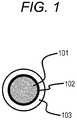
- FIG.1 is a schematic sectional view for illustrating an example of an electroconductive roller according to the present invention.
- An electroconductive supporting shaft of the present invention is ferrite-based stainless steel
- the mass% composition of the ferrite-based stainless steel contains 0.001% to 0.020% of carbon, 0.001% to 0.020% of nitrogen, 0.010% to 0.500% of silicon, 0.050% to 1.000% of manganese, 0.040% or less of phosphorus, 0.010% or less of sulfur, 12.000% to 25.000% of chromium, at least one of titanium and niobium, the titanium being incorporated at a content of from 0.020% to 0.500%, and the niobium being incorporated at a content of from 0.020% to 1.000%, and at least one of tin and antimony, the tin being incorporated at a content of from 0.005% to 2.000%, and the antimony being incorporated at a content of from 0.0050% to 1.000%, and the balance of the composition includes iron and an inevitable impurity.
- the stainless steel of such composition has high corrosion resistance, and has extremely large resistance to the corrosion of an electroconductive supporting shaft due to chlorine in an electroconductive layer containing epichlorohydrin. Meanwhile, the stainless steel of the composition can express a satisfactory adhesive force with an adhesive layer containing a phenol resin from the initial stage of adhesion.
- the content of carbon becomes lower, the corrosion resistance and moldability of the stainless steel improve. However, excessively reducing the content leads to an increase in cost. Accordingly, the content is from 0.001% to 0.020%.
- Nitrogen reduces the moldability, though the element is effective in improving the corrosion resistance. Accordingly, its content is preferably as low as possible. However, as in carbon, excessively reducing the content leads to an increase in cost. Accordingly, the content is from 0.001% to 0.020%.
- Silicon reduces the moldability, though the element is effective in improving the corrosion resistance. Accordingly, its content is from 0.010% to 0.500%.
- Manganese is an element effective for deacidification. On the other hand, excessive incorporation thereof reduces the corrosion resistance. Accordingly, its content is from 0.050% to 1.000%.
- Phosphorus is an element reducing the weldability and workability of the stainless steel. Accordingly, its content is 0.040% or less.
- sulfur is present as a sulfide that easily dissolves, such as calcium sulfide or manganese sulfide, the sulfide is liable to be a starting point for the corrosion of the stainless steel. Accordingly, its content is 0.010% or less.
- Chromium is an element extremely important for improving the corrosion resistance. As its content becomes higher, the corrosion resistance improves. On the other hand, as the content becomes higher, the moldability reduces. Accordingly, the content is from 12.000% to 25.000%.
- nitrogen, silicon, and chromium are elements important for improving the corrosion resistance.
- the corrosion resistance obtained merely by adding those elements is insufficient for resisting corrosion caused by a chloride derived from, for example, chlorine that has been liberated in the electroconductive layer containing the epichlorohydrin rubber. Accordingly, titanium, niobium, tin, and antimony need to be added.
- titanium or niobium or titanium and niobium is/are contained. Titanium and niobium are elements that improve the corrosion resistance and the moldability. However, excessive incorporation of titanium is responsible for surface defects of the stainless steel at the time of its production. In addition, excessive incorporation of niobium deteriorates the moldability. Accordingly, the content of titanium is from 0.020% to 0.500%, and the content of niobium is from 0.020% to 1.000%.
- tin or antimony or tin and antimony is/are contained.
- Tin and antimony are elements extremely effective in improving the corrosion resistance.
- excessive incorporation of any such element deteriorates the moldability. Accordingly, the content of tin is from 0.005% to 2.000%, and the content of antimony is from 0.005% to 1.000%.
- the term "inevitable impurity" refers to a trace component in a raw material or the like.
- examples thereof include oxygen, zirconium, lead, bismuth, zinc, vanadium, magnesium, cobalt, nickel, and molybdenum.
- Stainless steel having added thereto molybdenum has a high suppressing effect on the corrosion caused by a chloride derived from, for example, chlorine that has been liberated in the electroconductive layer containing the epichlorohydrin rubber, but as its content becomes higher, the adhesive force of the stainless steel with the adhesive layer reduces. Accordingly, the content is 0.2% or less.
- composition analysis of materials constituting the electroconductive supporting shaft can be performed by, for example, a fluorescent X-ray analysis method.
- a fully automatic fluorescent X-ray analyzer (trade name: Axios, manufactured by PANalytical, vessel: end window-type Rh, target: 2.4 kW, measurement environment: vacuum, elements to be measured: boron (B) to uranium (U)) can be used.
- quantification is performed from a fluorescent X-ray chart obtained with the fully automatic fluorescent X-ray analyzer by using the "Spectral Evaluation" of the dedicated software (trade name: Super Q MANAGER, manufactured by PANalytical) of the analyzer.
- the shape of the electroconductive supporting shaft is as follows: the outer periphery of a sectional shape of a portion to be held by a process cartridge has a circular shape. Examples thereof include a columnar shape, and such a shape that both of its end portions are each of a columnar shape and its central portion has a polygonal shape.
- the inside of the electroconductive supporting shaft may be solid, or may be hollow. When the electroconductive supporting shaft has a hollow structure, a cost therefor can be reduced. In addition, its weight is reduced, and hence rigidity which the process cartridge is required to have can be reduced, and a reduction in weight of the process cartridge and the simplification of its construction can be achieved.
- the electroconductive supporting shaft can be produced by a known method. Examples thereof include a method involving producing a columnar solid body or a columnar hollow body through drawing, and a method involving producing the columnar hollow body (cylindrical body) through press working from a flat plate.
- the material described in the foregoing is excellent in press workability, and is hence suitably used.
- seams occur on the outer peripheral surface of the electroconductive supporting shaft, but the seams can be changed in shape, or can be bonded by welding or the like, as required.
- the electroconductive supporting shaft is specifically, for example, an electroconductive supporting shaft obtained by subjecting a metal plate to press working to form the plate into a cylindrical shape.
- An adhesive layer of the present invention contains a phenol resin.
- the phenol resin has low permeabilities to gases, such as water vapor and a chlorine gas, and hence has the effect by which the difficulty with which chlorine in the electroconductive layer containing epichlorohydrin reaches the surface of the electroconductive supporting shaft is raised.
- the adhesive layer of the present invention may further contain another resin, a rubber, an electroconductive agent, a plasticizer, a thixotropy-imparting agent, a pigment, a dye, an anti-aging agent, an antioxidant, a dispersant, a solvent, and the like in addition to the phenol resin within the range in which the object of the present invention is not impaired.
- a resin such as a thermosetting resin or a thermoplastic resin is used.
- the resin to be suitably used include a urethane resin, an acrylic resin, an amide resin, an olefin resin, and an epoxy resin.
- an epoxy resin is particularly suitably used because the resin can trap chlorine that has been liberated from the epichlorohydrin rubber in the electroconductive layer, and hence has a suppressing effect on the corrosion of the electroconductive supporting shaft.
- any one of the following rubber components may also be mixed for improving the heat resistance of the adhesive layer, and improving an adhesive force between the adhesive layer and the electroconductive layer: a natural rubber, a butadiene rubber, a styrene-butadiene rubber (SBR), a nitrile rubber, an ethylene-propylene rubber (EPDM), a nitrile-butadiene rubber (NBR), a butyl rubber, and a urethane rubber.
- SBR styrene-butadiene rubber
- EPDM ethylene-propylene rubber
- NBR nitrile-butadiene rubber
- a butyl rubber a urethane rubber.
- a nitrile-butadiene rubber is particularly preferred because the rubber can improve the adhesive force between the electroconductive layer and the adhesive layer.
- electroconductive agent examples include: electroconductive particles of carbon black, graphite, electroconductive metal oxides (e.g., electroconductive titanium oxide and electroconductive tin oxide), and the like; and electroconductive composite particles obtained by compositing these electroconductive particles and other particles.
- the adhesive layer contains the phenol resin can be confirmed by, for example, a pyrolysis GC-MS method or FT-IR.
- an adhesive containing the phenol resin is commercially available as, for example, "METALOC U-20” or “METALOC N-23” (each of which is a trade name, manufactured by Toyokagaku Kenkyusho Co., Ltd.).
- the adhesive layer can be formed by an application method, such as roll application, electrostatic spray application, or dipping application.
- a solvent to be used in an application liquid needs only to be a solvent that can dissolve the phenol resin, and specific examples thereof include the following solvents: ketones, such as acetone, methyl ethyl ketone, and cyclohexanone; ethers, such as tetrahydrofuran, dioxane, and ethylene glycol monomethyl ether; esters, such as methyl acetate and ethyl acetate; and aromatic compounds, such as xylene, chlorobenzene, and dichlorobenzene.
- the adhesive layer may contain a fatty acid metal salt, a phosphite, and the like in order that the corrosion of the electroconductive supporting shaft may be suppressed by the adhesive layer.
- An electroconductive layer of the present invention contains an epichlorohydrin rubber.
- the epichlorohydrin rubber include an epichlorohydrin homopolymer, an epichlorohydrin-ethylene oxide copolymer, and an epichlorohydrin-ethylene oxide-allyl glycidyl ether terpolymer. Each of such polymers is used alone or in combination with another material. Examples of the other material to be used in combination include an acrylonitrile-butadiene copolymer, a hydrogenated acrylonitrile-butadiene copolymer, a silicone rubber, an acrylic rubber, and a urethane rubber.
- An electronic electroconductive agent or an ionic electroconductive agent can be added to the rubber forming the electroconductive layer as required for adjusting the electric resistance value of the layer.
- the electronic electroconductive agent include carbon black, graphite, oxides, such as tin oxide, metals, such as copper and silver, and electroconductive particles having imparted thereto electroconductivity by covering a particle surface with an oxide or a metal.
- the ionic electroconductive agent include materials each having an ion exchange property, such as a quaternary ammonium salt and a sulfonate.
- the electric resistance value of the electroconductive layer is 1 ⁇ 10 3 ⁇ cm or more and 1 ⁇ 10 9 ⁇ cm or less.
- the electroconductive layer contains the epichlorohydrin rubber can be confirmed by, for example, a pyrolysis GC-MS method or FT-IR.
- An electroconductive roller of the present invention can be used as an electroconductive member to be mounted on an image-forming apparatus (electrophotographic apparatus) adopting an electrophotographic process (electrophotographic system), such as a copying machine or a laser printer.
- the roller can be used as a charging roller, a developing roller, a transfer roller, or a charge-eliminating roller, or a conveying member, such as a sheet-feeding roller.
- FIG.1 is a schematic sectional view of an example of the electroconductive roller according to the present invention (schematic sectional view when the electroconductive roller is cut vertically to the axial direction of the electroconductive supporting shaft).
- the electroconductive roller of the present invention includes an electroconductive supporting shaft 101, an adhesive layer 102 arranged on its outer periphery, and an electroconductive layer 103 arranged on the adhesive layer 102.
- a surface layer may be arranged on the electroconductive layer as required.
- each of which the electroconductive roller of the present invention is used as a charging roller include the following process cartridge and electrophotographic apparatus. That is, the process cartridge includes: an electrophotographic photosensitive member; and a charging roller arranged to be in contact with the electrophotographic photosensitive member, the process cartridge being removably mounted onto a main body of an electrophotographic apparatus. Further, the electrophotographic apparatus includes: an electrophotographic photosensitive member; and a charging roller arranged to be in contact with the electrophotographic photosensitive member.
- an electroconductive roller having the following characteristics can be obtained.
- the roller is excellent in adhesive force between an electroconductive layer containing an epichlorohydrin rubber and an electroconductive supporting shaft, and even when the roller is used under high temperature and high humidity, the corrosion of the electroconductive supporting shaft resulting from liberated chlorine hardly occurs.
- Adhesive No. Material Parts by mass Adhesive 1 METALOC U-20 (trade name; manufactured by Toyokagaku Kenkyusho Co., Ltd.) 100 Adhesive 2 METALOC N-23 (trade name; manufactured by Toyokagaku Kenkyusho Co., Ltd.) 100 Carbon black (trade name: "MA100"; manufactured by Mitsubishi Chemical Corporation) 5
- Zinc oxide Zinc oxide of JIS 2 grade manufactured by Seido Chemical Industry Co., Ltd.
- Tetrabutylammonium perchlorate manufactured by Wako Pure Chemical Industries, Ltd.
- 1 Calcium carbonate (trade name: SILVER W; manufactured by Shiraishi Calcium Kaisha, Ltd.) 55 Carbon black (trade name: SEAST SO; manufactured by Tokai Carbon Co., Ltd.) 8 Stearic acid (processing aid) (manufactured by Kishida Chemical Co.,Ltd.) 2 Adipate (plasticizer) (trade name: POLYCIZER W305ELS; manufactured by DIC Corporation) 10 Sulfur (vulcanizing agent) (trade name: Sulfax; manufactured by Tsurumi Chemical Industries Co. Ltd.) 0.5 Dipentamethylenethiuram tetrasulfide (crosslinking aid) (trade name: NOCCELER TRA; manufactured by Ouchi Shinko Chemical
- an unvulcanized rubber composition 2 was obtained in the same manner as in the unvulcanized rubber composition 1 except that the epichlorohydrin rubber was changed to a product available under the trade name "CG-102" from Daiso Co., Ltd. (new company name: Osaka Soda Co., Ltd.).
- the adhesive 1 was applied over the whole periphery of the 230-mm range of the electroconductive supporting shaft 1 having a total length of 252 mm excluding both of its 11-mm end portions with a roll coater. After the adhesive had been applied, the electroconductive supporting shaft was heated in a hot-air drying furnace at a temperature of 170°C for 20 minutes to form an adhesive layer.
- a crosshead extruder having a mechanism for supplying the electroconductive supporting shaft having formed thereon the adhesive layer and a mechanism for discharging an unvulcanized rubber roller was prepared, and a die having an inner diameter of 12.5 mm was mounted on a crosshead.
- the temperatures of the extruder and the crosshead were each set to 80°C, and the speed at which the electroconductive supporting shaft having formed thereon the adhesive layer was conveyed was set to 60 mm/sec.
- the unvulcanized rubber composition 1 was supplied from the extruder under the conditions. Thus, such an unvulcanized rubber roller 1 that the coating layer (electroconductive layer) of the unvulcanized rubber composition 1 was formed on the outer periphery of the electroconductive supporting shaft in the crosshead was obtained.
- the unvulcanized rubber roller 1 was loaded into a hot-air vulcanizing furnace at a temperature of 170°C, and was heated for 60 minutes to provide a vulcanized rubber roller. After that, the end portions of the electroconductive layer were cut and removed. Finally, the surface of the electroconductive layer was polished with a rotary grindstone.
- an electroconductive elastic roller 1 having a diameter at each of positions distant from its central portion toward both of its end portions by 90 mm each of 8.4 mm, and having a diameter at the central portion of 8.5 mm was obtained.
- a solution having a solid content of 18 mass% was prepared by adding methyl isobutyl ketone to a caprolactone-modified acrylic polyol solution.
- a mixed solution was prepared by mixing 555.6 parts by mass of the solution (solid content of the caprolactone-modified acrylic polyol: 100 parts by mass) with other four kinds of materials shown in Table 4 below.
- the electroconductive elastic roller 1 was immersed in the application liquid for forming a surface layer while the upper end portion of the electroconductive supporting shaft was held with the longitudinal direction of the roller set to a vertical direction, and the liquid was applied by a dipping method.
- the time period for which the roller was immersed in the application liquid was set to 9 seconds, the initial and final speeds at which the roller was pulled up from the application liquid were set to 20 mm/s and 2 mm/s, respectively, and the speed was linearly changed with time between these speeds.
- the resultant applied product was air-dried at 23°C for 30 minutes.
- the dried product was dried in a hot-air circulating dryer set to 90°C for 1 hour. Further, the dried product was dried in a hot-air circulating dryer set to 160°C for 1 hour to form a surface layer on the outer peripheral surface of the electroconductive elastic roller.
- an electroconductive roller 1 was produced, and its performances were evaluated by the following methods.
- a cut was made in the surface layer of the electroconductive roller 1 along its axial direction with a cutter so as to reach the surface of the electroconductive supporting shaft. Further, a similar cut was made at a position distant from the position of the cut by 5 mm, and the coating layer (electroconductive layer+surface layer) having a width of 5 mm was slowly peeled from the electroconductive supporting shaft with a hand with an end portion thereof as a starting point. The state of a peeling interface at that time was observed, and the result of the evaluation was ranked by the following criteria.
- the resultant electroconductive roller was left to stand under a high-temperature and high-humidity environment (temperature: 40°C, relative humidity: 95%) for 1 month, and was then subjected to the following evaluation.
- an electrophotographic laser printer (trade name: LBP5400, manufactured by Canon Inc.) reconstructed so as to have a speed at which a recording medium was output of 200 mm/sec and an image resolution of 600 dpi.
- a charging roller was removed from the cartridge of the electrophotographic apparatus, and the electroconductive roller 1 was incorporated instead, followed by an image evaluation. All image evaluations were performed under low temperature and low humidity (temperature: 15°C, relative humidity: 10%), and a halftone image (such an image that horizontal lines each having a width of 1 dot in a direction vertical to the rotation direction of a photosensitive member were drawn at an interval of 2 dots in the rotation direction) was output and ranked by the following criteria.
- the resultant electroconductive roller was left to stand under a high-temperature and high-humidity environment (temperature: 40°C, relative humidity: 95%) for 1 month. After that, the same evaluation as the evaluation was performed and the result of the evaluation was ranked by the following criteria.
- the electroconductive layer of the electroconductive roller at a position corresponding to a site where the white hazy image appeared was peeled, and the surface of the electroconductive supporting shaft was observed and ranked by the following criteria.
- Electroconductive rollers 2 to 33 (Examples 2 to 33), an electroconductive roller C1 (Comparative Example 1), and an electroconductive roller C2 (Comparative Example 2) were each produced in the same manner as in Example 1 except that the electroconductive supporting shaft, the adhesive layer, and the unvulcanized rubber composition for the electroconductive layer were changed as shown in Table 5, and their performances were evaluated. The results of the evaluations are shown in Table 6.
- the electroconductive rollers of Examples 1 to 33 each having the adhesive layer containing the phenol resin on the electroconductive supporting shaft of the present invention, and each having the electroconductive layer containing the epichlorohydrin rubber on the adhesive layer are each excellent in initial adhesive force between the electroconductive supporting shaft and the adhesive layer.
- the corrosion of the electroconductive supporting shaft can be suppressed.
- the standing under high temperature and high humidity is prolonged, no problems occur in practical use.
- the electroconductive roller described in Comparative Example 2 had an insufficient initial adhesive force between the electroconductive supporting shaft and the adhesive layer. This is interpreted as being because the electroconductive supporting shaft contains molybdenum.
- an electroconductive roller including: an electroconductive supporting shaft; an adhesive layer on the electroconductive supporting shaft; and an electroconductive layer on the adhesive layer, in which: the adhesive layer contains a phenol resin; the electroconductive layer contains an epichlorohydrin rubber; the electroconductive supporting shaft includes ferrite-based stainless steel.
Landscapes
- Chemical & Material Sciences (AREA)
- Engineering & Computer Science (AREA)
- Materials Engineering (AREA)
- Mechanical Engineering (AREA)
- Metallurgy (AREA)
- Organic Chemistry (AREA)
- Physics & Mathematics (AREA)
- Plasma & Fusion (AREA)
- General Physics & Mathematics (AREA)
- Rolls And Other Rotary Bodies (AREA)
- Electrostatic Charge, Transfer And Separation In Electrography (AREA)
- Dry Development In Electrophotography (AREA)
- Electrophotography Configuration And Component (AREA)
Abstract
Description
- The present invention relates to an electroconductive roller, and a process cartridge and an electrophotographic apparatus each including the electroconductive roller.
- In an electrophotographic apparatus serving as an image-forming apparatus adopting an electrophotographic system, an electroconductive roller has been used in various applications. Examples thereof include a charging roller, a developing roller, and a transfer roller. As such electroconductive roller, there is known a roller obtained by laminating an adhesive layer and an electroconductive layer on an electroconductive supporting shaft made of a metal, such as iron.
- Incidentally, when an electroconductive roller including an electroconductive layer containing an epichlorohydrin rubber is used under high-temperature and high-humidity conditions over a long time period, its electroconductive supporting shaft is corroded by a chloride derived from chlorine that has been liberated in the electroconductive layer in some cases.
-
Japanese Patent Application Laid-Open No. 2012- 189748 - However, an investigation made by the inventors of the present invention has found that in the case where stainless steel excellent in corrosion resistance is used in an electroconductive supporting shaft, an adhesive property between the electroconductive supporting shaft and an electroconductive layer containing an epichlorohydrin rubber involves a problem even when a phenol resin-based adhesive having a high adhesive force is used.
- The present invention is directed to the providing an electroconductive roller having the following characteristics. The roller is excellent in adhesive force between an electroconductive layer containing an epichlorohydrin rubber and an electroconductive supporting shaft, and even when the roller is used under high temperature and high humidity, the corrosion of the electroconductive supporting shaft resulting from liberated chlorine hardly occurs. The present invention is also directed to providing a process cartridge and an electrophotographic apparatus conducive to stable formation of high-quality electrophotographic images.
- According to one embodiment of the present invention, there is provided an electroconductive roller, including: an electroconductive supporting shaft; an adhesive layer on the electroconductive supporting shaft; and an electroconductive layer on the adhesive layer, in which: the adhesive layer contains a phenol resin; the electroconductive layer contains an epichlorohydrin rubber; the electroconductive supporting shaft includes ferrite-based stainless steel; a mass% composition of the ferrite-based stainless steel contains 0.001% to 0.020% of carbon, 0.001% to 0.020% of nitrogen, 0.010% to 0.500% of silicon, 0.050% to 1.000% of manganese, 0.040% or less of phosphorus, 0.010% or less of sulfur, 12.000% to 25.000% of chromium, at least one of titanium and niobium, the titanium being incorporated at a content of from 0.020% to 0.500%, and the niobium being incorporated at a content of from 0.020% to 1.000%, and at least one of tin and antimony, the tin being incorporated at a content of from 0.005% to 2.000%, and the antimony being incorporated at a content of from 0.0050% to 1.000%; and the balance of the composition includes iron and an inevitable impurity.
- Further, according to another embodiment of the present invention, there is provided a process cartridge, including: an electrophotographic photosensitive member; and a charging roller arranged to be in contact with the electrophotographic photosensitive member, the process cartridge being removably mounted onto a main body of an electrophotographic apparatus, in which the charging roller includes the above-mentioned electroconductive roller.
- According to yet another embodiment of the present invention, there is provided an electrophotographic apparatus, including: an electrophotographic photosensitive member; and a charging roller arranged to be in contact with the electrophotographic photosensitive member, in which the charging roller includes the above-mentioned electroconductive roller.
- Further features of the present invention will become apparent from the following description of exemplary embodiments with reference to the attached drawings.
-
FIG.1 is a schematic sectional view for illustrating an example of an electroconductive roller according to the present invention. - Preferred embodiments of the present invention will now be described in detail in accordance with the accompanying drawings.
- In view of the knowledge that when stainless steel having high corrosion resistance, such as SUS444, is used as an electroconductive supporting shaft, and a phenol resin-based adhesive is used as an adhesive, an adhesive force between the electroconductive supporting shaft and an electroconductive layer containing an epichlorohydrin rubber is insufficient, the inventors of the present invention have made extensive investigations on a material for the electroconductive supporting shaft. As a result, the inventors have found the composition of an alloy suitable for adhesion with the electroconductive layer containing the epichlorohydrin rubber as the material for the electroconductive supporting shaft.
- An electroconductive supporting shaft of the present invention is ferrite-based stainless steel, the mass% composition of the ferrite-based stainless steel contains 0.001% to 0.020% of carbon, 0.001% to 0.020% of nitrogen, 0.010% to 0.500% of silicon, 0.050% to 1.000% of manganese, 0.040% or less of phosphorus, 0.010% or less of sulfur, 12.000% to 25.000% of chromium, at least one of titanium and niobium, the titanium being incorporated at a content of from 0.020% to 0.500%, and the niobium being incorporated at a content of from 0.020% to 1.000%, and at least one of tin and antimony, the tin being incorporated at a content of from 0.005% to 2.000%, and the antimony being incorporated at a content of from 0.0050% to 1.000%, and the balance of the composition includes iron and an inevitable impurity.
- The stainless steel of such composition has high corrosion resistance, and has extremely large resistance to the corrosion of an electroconductive supporting shaft due to chlorine in an electroconductive layer containing epichlorohydrin. Meanwhile, the stainless steel of the composition can express a satisfactory adhesive force with an adhesive layer containing a phenol resin from the initial stage of adhesion.
- As the content of carbon becomes lower, the corrosion resistance and moldability of the stainless steel improve. However, excessively reducing the content leads to an increase in cost. Accordingly, the content is from 0.001% to 0.020%.
- Nitrogen reduces the moldability, though the element is effective in improving the corrosion resistance. Accordingly, its content is preferably as low as possible. However, as in carbon, excessively reducing the content leads to an increase in cost. Accordingly, the content is from 0.001% to 0.020%.
- Silicon reduces the moldability, though the element is effective in improving the corrosion resistance. Accordingly, its content is from 0.010% to 0.500%.
- Manganese is an element effective for deacidification. On the other hand, excessive incorporation thereof reduces the corrosion resistance. Accordingly, its content is from 0.050% to 1.000%.
- Phosphorus is an element reducing the weldability and workability of the stainless steel. Accordingly, its content is 0.040% or less.
- When sulfur is present as a sulfide that easily dissolves, such as calcium sulfide or manganese sulfide, the sulfide is liable to be a starting point for the corrosion of the stainless steel. Accordingly, its content is 0.010% or less.
- Chromium is an element extremely important for improving the corrosion resistance. As its content becomes higher, the corrosion resistance improves. On the other hand, as the content becomes higher, the moldability reduces. Accordingly, the content is from 12.000% to 25.000%.
- Of the above-mentioned elements, nitrogen, silicon, and chromium are elements important for improving the corrosion resistance. On the other hand, the corrosion resistance obtained merely by adding those elements is insufficient for resisting corrosion caused by a chloride derived from, for example, chlorine that has been liberated in the electroconductive layer containing the epichlorohydrin rubber. Accordingly, titanium, niobium, tin, and antimony need to be added.
- In the stainless-steel, titanium or niobium or titanium and niobium is/are contained. Titanium and niobium are elements that improve the corrosion resistance and the moldability. However, excessive incorporation of titanium is responsible for surface defects of the stainless steel at the time of its production. In addition, excessive incorporation of niobium deteriorates the moldability. Accordingly, the content of titanium is from 0.020% to 0.500%, and the content of niobium is from 0.020% to 1.000%.
- In the stainless-steel, tin or antimony or tin and antimony is/are contained. Tin and antimony are elements extremely effective in improving the corrosion resistance. However, excessive incorporation of any such element deteriorates the moldability. Accordingly, the content of tin is from 0.005% to 2.000%, and the content of antimony is from 0.005% to 1.000%.
- In the present invention, the term "inevitable impurity" refers to a trace component in a raw material or the like. Examples thereof include oxygen, zirconium, lead, bismuth, zinc, vanadium, magnesium, cobalt, nickel, and molybdenum. Stainless steel having added thereto molybdenum has a high suppressing effect on the corrosion caused by a chloride derived from, for example, chlorine that has been liberated in the electroconductive layer containing the epichlorohydrin rubber, but as its content becomes higher, the adhesive force of the stainless steel with the adhesive layer reduces. Accordingly, the content is 0.2% or less.
- The composition analysis of materials constituting the electroconductive supporting shaft can be performed by, for example, a fluorescent X-ray analysis method.
- More specifically, for example, a fully automatic fluorescent X-ray analyzer (trade name: Axios, manufactured by PANalytical, vessel: end window-type Rh, target: 2.4 kW, measurement environment: vacuum, elements to be measured: boron (B) to uranium (U)) can be used. In addition, quantification is performed from a fluorescent X-ray chart obtained with the fully automatic fluorescent X-ray analyzer by using the "Spectral Evaluation" of the dedicated software (trade name: Super Q MANAGER, manufactured by PANalytical) of the analyzer.
- The shape of the electroconductive supporting shaft is as follows: the outer periphery of a sectional shape of a portion to be held by a process cartridge has a circular shape. Examples thereof include a columnar shape, and such a shape that both of its end portions are each of a columnar shape and its central portion has a polygonal shape. In addition, the inside of the electroconductive supporting shaft may be solid, or may be hollow. When the electroconductive supporting shaft has a hollow structure, a cost therefor can be reduced. In addition, its weight is reduced, and hence rigidity which the process cartridge is required to have can be reduced, and a reduction in weight of the process cartridge and the simplification of its construction can be achieved.
- The electroconductive supporting shaft can be produced by a known method. Examples thereof include a method involving producing a columnar solid body or a columnar hollow body through drawing, and a method involving producing the columnar hollow body (cylindrical body) through press working from a flat plate. The material described in the foregoing is excellent in press workability, and is hence suitably used. When the columnar hollow body is produced through the press working from the flat plate, seams occur on the outer peripheral surface of the electroconductive supporting shaft, but the seams can be changed in shape, or can be bonded by welding or the like, as required. The electroconductive supporting shaft is specifically, for example, an electroconductive supporting shaft obtained by subjecting a metal plate to press working to form the plate into a cylindrical shape.
- An adhesive layer of the present invention contains a phenol resin. The phenol resin has low permeabilities to gases, such as water vapor and a chlorine gas, and hence has the effect by which the difficulty with which chlorine in the electroconductive layer containing epichlorohydrin reaches the surface of the electroconductive supporting shaft is raised. The adhesive layer of the present invention may further contain another resin, a rubber, an electroconductive agent, a plasticizer, a thixotropy-imparting agent, a pigment, a dye, an anti-aging agent, an antioxidant, a dispersant, a solvent, and the like in addition to the phenol resin within the range in which the object of the present invention is not impaired.
- As the other resin, a resin such as a thermosetting resin or a thermoplastic resin is used. Specific examples of the resin to be suitably used include a urethane resin, an acrylic resin, an amide resin, an olefin resin, and an epoxy resin. Of those, an epoxy resin is particularly suitably used because the resin can trap chlorine that has been liberated from the epichlorohydrin rubber in the electroconductive layer, and hence has a suppressing effect on the corrosion of the electroconductive supporting shaft.
- In addition to those resins, for example, any one of the following rubber components may also be mixed for improving the heat resistance of the adhesive layer, and improving an adhesive force between the adhesive layer and the electroconductive layer: a natural rubber, a butadiene rubber, a styrene-butadiene rubber (SBR), a nitrile rubber, an ethylene-propylene rubber (EPDM), a nitrile-butadiene rubber (NBR), a butyl rubber, and a urethane rubber. Of those, a nitrile-butadiene rubber is particularly preferred because the rubber can improve the adhesive force between the electroconductive layer and the adhesive layer.
- Examples of the electroconductive agent include: electroconductive particles of carbon black, graphite, electroconductive metal oxides (e.g., electroconductive titanium oxide and electroconductive tin oxide), and the like; and electroconductive composite particles obtained by compositing these electroconductive particles and other particles.
- Whether or not the adhesive layer contains the phenol resin can be confirmed by, for example, a pyrolysis GC-MS method or FT-IR.
- In addition, an adhesive containing the phenol resin is commercially available as, for example, "METALOC U-20" or "METALOC N-23" (each of which is a trade name, manufactured by Toyokagaku Kenkyusho Co., Ltd.).
- The adhesive layer can be formed by an application method, such as roll application, electrostatic spray application, or dipping application. A solvent to be used in an application liquid needs only to be a solvent that can dissolve the phenol resin, and specific examples thereof include the following solvents: ketones, such as acetone, methyl ethyl ketone, and cyclohexanone; ethers, such as tetrahydrofuran, dioxane, and ethylene glycol monomethyl ether; esters, such as methyl acetate and ethyl acetate; and aromatic compounds, such as xylene, chlorobenzene, and dichlorobenzene.
- Further, the adhesive layer may contain a fatty acid metal salt, a phosphite, and the like in order that the corrosion of the electroconductive supporting shaft may be suppressed by the adhesive layer.
- It has been generally known that when the epoxy resin, the fatty acid metal salt, and the phosphite are mixed, these three kinds of materials react with a halogen atom, such as chlorine, to produce a stable compound, thereby making the halogen atom, such as chlorine, harmless.
- An electroconductive layer of the present invention contains an epichlorohydrin rubber. Specific examples of the epichlorohydrin rubber include an epichlorohydrin homopolymer, an epichlorohydrin-ethylene oxide copolymer, and an epichlorohydrin-ethylene oxide-allyl glycidyl ether terpolymer. Each of such polymers is used alone or in combination with another material. Examples of the other material to be used in combination include an acrylonitrile-butadiene copolymer, a hydrogenated acrylonitrile-butadiene copolymer, a silicone rubber, an acrylic rubber, and a urethane rubber.
- An electronic electroconductive agent or an ionic electroconductive agent can be added to the rubber forming the electroconductive layer as required for adjusting the electric resistance value of the layer. Examples of the electronic electroconductive agent include carbon black, graphite, oxides, such as tin oxide, metals, such as copper and silver, and electroconductive particles having imparted thereto electroconductivity by covering a particle surface with an oxide or a metal. Examples of the ionic electroconductive agent include materials each having an ion exchange property, such as a quaternary ammonium salt and a sulfonate.
- In addition, a filler, a softener, a processing aid, a tackifier, an antitack agent, a dispersant, a foaming agent, roughening particles, and the like, which are generally used as a resin compounding agent, can be added to the rubber within the range in which the effect of the present invention is not impaired. As a guideline, the electric resistance value of the electroconductive layer is 1×10³ Ω·cm or more and 1×10⁹ Ω·cm or less.
- Whether or not the electroconductive layer contains the epichlorohydrin rubber can be confirmed by, for example, a pyrolysis GC-MS method or FT-IR.
- An electroconductive roller of the present invention can be used as an electroconductive member to be mounted on an image-forming apparatus (electrophotographic apparatus) adopting an electrophotographic process (electrophotographic system), such as a copying machine or a laser printer. Specifically, the roller can be used as a charging roller, a developing roller, a transfer roller, or a charge-eliminating roller, or a conveying member, such as a sheet-feeding roller.
- The electroconductive roller of the present invention is described below by way of Examples in each of which a charging roller serving as a typical example of the electroconductive roller is used, but the present invention is not limited thereto.
FIG.1 is a schematic sectional view of an example of the electroconductive roller according to the present invention (schematic sectional view when the electroconductive roller is cut vertically to the axial direction of the electroconductive supporting shaft). As illustrated inFIG.1 , the electroconductive roller of the present invention includes anelectroconductive supporting shaft 101, anadhesive layer 102 arranged on its outer periphery, and anelectroconductive layer 103 arranged on theadhesive layer 102. In addition, a surface layer may be arranged on the electroconductive layer as required. - Specific examples in each of which the electroconductive roller of the present invention is used as a charging roller include the following process cartridge and electrophotographic apparatus. That is, the process cartridge includes: an electrophotographic photosensitive member; and a charging roller arranged to be in contact with the electrophotographic photosensitive member, the process cartridge being removably mounted onto a main body of an electrophotographic apparatus. Further, the electrophotographic apparatus includes: an electrophotographic photosensitive member; and a charging roller arranged to be in contact with the electrophotographic photosensitive member.
- According to one embodiment of the present invention, an electroconductive roller having the following characteristics can be obtained. The roller is excellent in adhesive force between an electroconductive layer containing an epichlorohydrin rubber and an electroconductive supporting shaft, and even when the roller is used under high temperature and high humidity, the corrosion of the electroconductive supporting shaft resulting from liberated chlorine hardly occurs.
- The present invention is specifically described below by way of Production Examples and Examples.
- Columnar solid rods formed of materials 1 to 29 of compositions shown in Table 1 below (the compositions were represented in a mass% unit), the rods each having a total length of 252 mm and a diameter of 6 mm, were prepared as electroconductive supporting shafts 1 to 29. It should be noted that the material 29 is SUS444. In addition, flat plates (thickness: 0.6 mm) formed of the material 1 and the material 2 were subjected to press working to prepare columnar hollow rods (cylindrical bodies) each having a total length of 252 mm and a diameter of 6 mm as electroconductive supporting shafts 30 and 31.
Table 1 Electroconductive supporting shaft No 1 2 3 4 5 6 7 8 9 10 Material 1 Material 2 Material 3 Material 4 Material 5 Material 6 Material 7 Material 8 Material 9 Material 10 C 0.004 0.004 0.003 0.004 0.003 0.004 0.004 0.004 0.004 0.004 Si 0.110 0.060 0.120 0.050 0.130 0.070 0.110 0.050 0.110 0.070 Mn 0.190 0.100 0.200 0.110 0.210 0.110 0.190 0.110 0.190 0.110 P 0.024 0.023 0.026 0.022 0.022 0.024 0.024 0.039 0.040 0.024 S 0.001 0.001 0.001 0.002 0.009 0.001 0.002 0.001 0.001 0.001 Ni Cr 14.050 17.320 14.300 17.700 14.050 17.400 14.080 17.250 14.210 17.250 Ti 0.080 0.070 0.070 0.070 0.080 0.180 0.190 0.170 0.120 0.160 Nb 0.130 0.120 0.110 0.130 0.140 Sn 0.120 0.210 0.050 0.005 1.990 0.005 Sb 0.060 0.110 0.100 0.005 0.980 0.005 N 0.009 0.011 0.010 0.011 0.012 0.009 0.009 0.009 0.008 0.010 Mo Electroconductive supporting shaft No 11 12 13 14 15 16 17 18 19 20 Material 11 Material 12 Material 13 Material 14 Material 15 Material 16 Material 17 Material 18 Material 19 Material 20 C 0.004 0.004 0.004 0.004 0.001 0.002 0.002 0.020 0.020 0.002 Si 0.110 0.080 0.120 0.080 0.010 0.090 0.080 0.090 0.500 0.090 Mn 0.200 0.100 0.200 0.100 0.200 0.100 0.180 0.100 0.180 0.100 P 0.024 0.021 0.022 0.021 0.026 0.024 0.026 0.024 0.026 0.024 S 0.002 0.001 0.002 0.001 0.001 0.003 0.001 0.003 0.001 0.003 Ni Cr 14.110 17.330 14.080 17.400 14.810 17.600 14.080 16.980 14.810 17.720 Ti 0.130 0.160 0.190 0.180 0.021 0.180 0.020 0.490 0.031 Nb 0.020 0.021 0.990 Sn 0.011 0.990 0.050 0.011 0.990 Sb 0.005 0.490 0.100 0.110 0.120 0.100 N 0.009 0.007 0.009 0.009 0.001 0.003 0.004 0.019 0.020 0.005 Mo Electroconductive supporting shaft No 21 22 23 24 25 26 27 28 29 Material 21 Material 22 Material 23 Material 24 Material 25 Material 26 Material 27 Material 28 Material 29 C 0.001 0.002 0.020 0.004 0.004 0.004 0.004 0.070 0.007 Si 0.080 0.080 0.090 0.070 0.110 0.080 0.120 0.290 0.310 Mn 1.000 0.100 0.050 0.110 0.190 0.110 0.170 0.600 0.180 P 0.027 0.021 0.026 0.023 0.024 0.024 0.024 0.025 0.026 S 0.001 0.001 0.001 0.001 0.001 0.001 0.001 0.001 0.002 Ni 0.110 0.130 Cr 14.330 17.680 14.420 12.010 15.030 21.980 24.890 16.230 18.400 Ti 0.032 0.290 0.080 0.080 0.070 0.070 Nb 0.052 0.051 0.580 0.120 0.130 0.120 0.130 0.400 Sn 0.050 0.060 0.200 0.140 0.210 0.120 Sb 0.130 0.090 0.100 N 0.002 0.003 0.009 0.011 0.009 0.011 0.009 0.010 Mo 1.960 - An adhesive 1 and an adhesive 2 shown in Table 2 below were prepared as adhesives for forming adhesive layers each containing a phenol resin.
Table 2 Adhesive No. Material Parts by mass Adhesive 1 METALOC U-20 (trade name; manufactured by Toyokagaku Kenkyusho Co., Ltd.) 100 Adhesive 2 METALOC N-23 (trade name; manufactured by Toyokagaku Kenkyusho Co., Ltd.) 100 Carbon black (trade name: "MA100"; manufactured by Mitsubishi Chemical Corporation) 5 - Materials shown in Table 3 below were mixed with an open roll to provide an unvulcanized rubber composition 1 containing epichlorohydrin.
Table 3 Material Part(s) by mass Epichlorohydrin rubber (trade name; EPION 301; manufactured by Daiso Co., Ltd. (new company name: Osaka Soda Co., Ltd.)) 100 Zinc oxide (zinc oxide of JIS 2 grade manufactured by Seido Chemical Industry Co., Ltd.) 5 Tetrabutylammonium perchlorate (manufactured by Wako Pure Chemical Industries, Ltd.) 1 Calcium carbonate (trade name: SILVER W; manufactured by Shiraishi Calcium Kaisha, Ltd.) 55 Carbon black (trade name: SEAST SO; manufactured by Tokai Carbon Co., Ltd.) 8 Stearic acid (processing aid) (manufactured by Kishida Chemical Co.,Ltd.) 2 Adipate (plasticizer) (trade name: POLYCIZER W305ELS; manufactured by DIC Corporation) 10 Sulfur (vulcanizing agent) (trade name: Sulfax; manufactured by Tsurumi Chemical Industries Co. Ltd.) 0.5 Dipentamethylenethiuram tetrasulfide (crosslinking aid) (trade name: NOCCELER TRA; manufactured by Ouchi Shinko Chemical Industrial Co., Ltd.) 2 - In addition, an unvulcanized rubber composition 2 was obtained in the same manner as in the unvulcanized rubber composition 1 except that the epichlorohydrin rubber was changed to a product available under the trade name "CG-102" from Daiso Co., Ltd. (new company name: Osaka Soda Co., Ltd.).
- The adhesive 1 was applied over the whole periphery of the 230-mm range of the electroconductive supporting shaft 1 having a total length of 252 mm excluding both of its 11-mm end portions with a roll coater. After the adhesive had been applied, the electroconductive supporting shaft was heated in a hot-air drying furnace at a temperature of 170°C for 20 minutes to form an adhesive layer.
- Next, a crosshead extruder having a mechanism for supplying the electroconductive supporting shaft having formed thereon the adhesive layer and a mechanism for discharging an unvulcanized rubber roller was prepared, and a die having an inner diameter of 12.5 mm was mounted on a crosshead. The temperatures of the extruder and the crosshead were each set to 80°C, and the speed at which the electroconductive supporting shaft having formed thereon the adhesive layer was conveyed was set to 60 mm/sec. The unvulcanized rubber composition 1 was supplied from the extruder under the conditions. Thus, such an unvulcanized rubber roller 1 that the coating layer (electroconductive layer) of the unvulcanized rubber composition 1 was formed on the outer periphery of the electroconductive supporting shaft in the crosshead was obtained.
- Next, the unvulcanized rubber roller 1 was loaded into a hot-air vulcanizing furnace at a temperature of 170°C, and was heated for 60 minutes to provide a vulcanized rubber roller. After that, the end portions of the electroconductive layer were cut and removed. Finally, the surface of the electroconductive layer was polished with a rotary grindstone. Thus, an electroconductive elastic roller 1 having a diameter at each of positions distant from its central portion toward both of its end portions by 90 mm each of 8.4 mm, and having a diameter at the central portion of 8.5 mm was obtained.
- A solution having a solid content of 18 mass% was prepared by adding methyl isobutyl ketone to a caprolactone-modified acrylic polyol solution. A mixed solution was prepared by mixing 555.6 parts by mass of the solution (solid content of the caprolactone-modified acrylic polyol: 100 parts by mass) with other four kinds of materials shown in Table 4 below.
Table 4 Material Part(s) by mass Caprolactone-modified acrylic polyol (trade name: PLACCEL DC2016; manufactured by Daicel Chemical Industries, Ltd.) 100 Carbon black (HAF) (trade name: MA100; manufactured by Mitsubishi Chemical Corporation) 16 Acicular rutile titanium oxide fine particles (trade name: SMY150IB;; manufactured by Tayca Corporation) 35 Modified dimethyl silicone oil (trade name: SH28PA; manufactured by Dow Corning Toray Co., Ltd.) 0.1 7:3 Mixture of hexamethylene diisocyanate (HDI) and isophorone diisocyanate (IPDI) (trade name: VESTANAT B1370; manufactured by Degussa-Hüls AG (EVONIK Industries AG)) 80.14 - 210 Grams of the mixed solution and 200 g of glass beads having an average particle diameter of 0.8 mm serving as media were mixed in a 450-mL glass bottle, and were dispersed with a paint shaker disperser for 24 hours. After the dispersion, 5.44 parts by mass (amount corresponding to 20 parts by mass with respect to 100 parts by mass of the acrylic polyol) of crosslinking-type acrylic particles "MR50G" (trade name: manufactured by Soken Chemical & Engineering Co., Ltd.) were added as resin particles to the resultant, and then the mixture was further dispersed for 30 minutes to provide an application liquid 1 for forming a surface layer.
- Next, the electroconductive elastic roller 1 was immersed in the application liquid for forming a surface layer while the upper end portion of the electroconductive supporting shaft was held with the longitudinal direction of the roller set to a vertical direction, and the liquid was applied by a dipping method. The time period for which the roller was immersed in the application liquid was set to 9 seconds, the initial and final speeds at which the roller was pulled up from the application liquid were set to 20 mm/s and 2 mm/s, respectively, and the speed was linearly changed with time between these speeds. The resultant applied product was air-dried at 23°C for 30 minutes. Next, the dried product was dried in a hot-air circulating dryer set to 90°C for 1 hour. Further, the dried product was dried in a hot-air circulating dryer set to 160°C for 1 hour to form a surface layer on the outer peripheral surface of the electroconductive elastic roller. Thus, an electroconductive roller 1 was produced, and its performances were evaluated by the following methods.
- A cut was made in the surface layer of the electroconductive roller 1 along its axial direction with a cutter so as to reach the surface of the electroconductive supporting shaft. Further, a similar cut was made at a position distant from the position of the cut by 5 mm, and the coating layer (electroconductive layer+surface layer) having a width of 5 mm was slowly peeled from the electroconductive supporting shaft with a hand with an end portion thereof as a starting point. The state of a peeling interface at that time was observed, and the result of the evaluation was ranked by the following criteria. It should be noted that when an adhesive force between the electroconductive supporting shaft and the adhesive layer is sufficient, the electroconductive layer or the adhesive layer undergoes a cohesive failure, and when the adhesive force between the electroconductive supporting shaft and the adhesive layer is insufficient, the electroconductive supporting shaft and the adhesive layer easily peel off each other. In addition, an electroconductive roller in which peeling occurred at an interface between an electroconductive supporting shaft and an adhesive layer was not subjected to evaluations "4-2" and thereafter.
- Rank A: The peeling occurred by virtue of the cohesive failure of the electroconductive layer or the adhesive layer.
- Rank C: The peeling occurred at the interface between the electroconductive supporting shaft and the adhesive layer.
- The resultant electroconductive roller was left to stand under a high-temperature and high-humidity environment (temperature: 40°C, relative humidity: 95%) for 1 month, and was then subjected to the following evaluation.
- Prepared as an electrophotographic apparatus was an electrophotographic laser printer (trade name: LBP5400, manufactured by Canon Inc.) reconstructed so as to have a speed at which a recording medium was output of 200 mm/sec and an image resolution of 600 dpi. A charging roller was removed from the cartridge of the electrophotographic apparatus, and the electroconductive roller 1 was incorporated instead, followed by an image evaluation. All image evaluations were performed under low temperature and low humidity (temperature: 15°C, relative humidity: 10%), and a halftone image (such an image that horizontal lines each having a width of 1 dot in a direction vertical to the rotation direction of a photosensitive member were drawn at an interval of 2 dots in the rotation direction) was output and ranked by the following criteria.
- Rank A: No white hazy image is present.
- Rank C: The image has a white hazy product.
- Further, after the evaluation, the resultant electroconductive roller was left to stand under a high-temperature and high-humidity environment (temperature: 40°C, relative humidity: 95%) for 1 month. After that, the same evaluation as the evaluation was performed and the result of the evaluation was ranked by the following criteria.
- Rank A: No white hazy image is present.
- Rank B: A slight white hazy image is observed but causes no problems in practical use.
- Rank C: The image has a white hazy product.
- With regard to such an electroconductive roller that a white hazy image appeared in the image evaluation after standing under high temperature and high humidity described in the section "4-2", the electroconductive layer of the electroconductive roller at a position corresponding to a site where the white hazy image appeared was peeled, and the surface of the electroconductive supporting shaft was observed and ranked by the following criteria.
- Rank A: No rust occurs.
- Rank B: No rust occurs, but extremely slight peeling occurs at the interface between the adhesive layer and the electroconductive supporting shaft.
- Rank C: Rust occurs.
- The results of the evaluations are shown in Table 6.
- Electroconductive rollers 2 to 33 (Examples 2 to 33), an electroconductive roller C1 (Comparative Example 1), and an electroconductive roller C2 (Comparative Example 2) were each produced in the same manner as in Example 1 except that the electroconductive supporting shaft, the adhesive layer, and the unvulcanized rubber composition for the electroconductive layer were changed as shown in Table 5, and their performances were evaluated. The results of the evaluations are shown in Table 6.
Table 5 Electroconductive roller No Electroconductive supporting shaft No Adhesive layer Electroconductive layer Example 1 1 1 Adhesive 1 Unvulcanized rubber composition 1 Example 2 2 2 Same as above Same as above Example 3 3 3 Same as above Same as above Example 4 4 4 Same as above Same as above Example 5 5 5 Same as above Same as above Example 6 6 6 Same as above Same as above Example 7 7 7 Same as above Same as above Example 8 8 8 Same as above Same as above Example 9 9 9 Same as above Same as above Example 10 10 10 Same as above Same as above Example 11 11 11 Same as above Same as above Example 12 12 12 Same as above Same as above Example 13 13 13 Same as above Same as above Example 14 14 14 Same as above Same as above Example 15 15 15 Same as above Same as above Example 16 16 16 Same as above Same as above Example 17 17 17 Same as above Same as above Example 18 18 18 Same as above Same as above Example 19 19 19 Same as above Same as above Example 20 20 20 Same as above Same as above Example 21 21 21 Same as above Same as above Example 22 22 22 Same as above Same as above Example 23 23 23 Same as above Same as above Example 24 24 24 Same as above Same as above Example 25 25 25 Same as above Same as above Example 26 26 26 Same as above Same as above Example 27 27 27 Same as above Same as above Example 28 28 1 Same as above Unvulcanized rubber composition 2 Example 29 29 2 Same as above Same as above Example 30 30 1 Adhesive 2 Unvulcanized rubber composition 1 Example 31 31 2 Same as above Same as above Example 32 32 30 Adhesive 1 Same as above Example 33 33 31 Same as above Unvulcanized rubber composition 2 Comparative Example 1 C1 28 Same as above Unvulcanized rubber composition 1 Comparative Example 2 C2 29 Same as above Same as above Table 6 Initial adhesive force Image after standing under high temperature and high humidity Corrosion and peeling After 1 month After 2 months Example 1 A A A - Example 2 A A A - Example 3 A A A - Example 4 A A A - Example 5 A A A - Example 6 A A B B Example 7 A A B B Example 8 A A A - Example 9 A A A - Example 10 A A B B Example 11 A A A - Example 12 A A A - Example 13 A A A - Example 14 A A A - Example 15 A A B B Example 16 A A B B Example 17 A A B B Example 18 A A A - Example 19 A A A - Example 20 A A A - Example 21 A A A - Example 22 A A A - Example 23 A A A - Example 24 A A B B Example 25 A A A - Example 26 A A A - Example 27 A A A - Example 28 A A A - Example 29 A A A - Example 30 A A A - Example 31 A A A - Example 32 A A A - Example 33 A A A - Comparative Example 1 A C - C Comparative Example 2 C - - - - As shown in Table 6, the electroconductive rollers of Examples 1 to 33 each having the adhesive layer containing the phenol resin on the electroconductive supporting shaft of the present invention, and each having the electroconductive layer containing the epichlorohydrin rubber on the adhesive layer are each excellent in initial adhesive force between the electroconductive supporting shaft and the adhesive layer. In addition, even when each of the rollers is left to stand under high temperature and high humidity, the corrosion of the electroconductive supporting shaft can be suppressed. In addition, even when the standing under high temperature and high humidity is prolonged, no problems occur in practical use.
- With regard to the electroconductive roller described in Comparative Example 1, a white hazy image occurred in an image after standing under high temperature and high humidity. When the electroconductive layer and the adhesive layer were peeled, and the surface of the electroconductive supporting shaft was observed, it was found that corrosion occurred in a portion corresponding to a site causing white haze on the image. This is interpreted as being because the electroconductive supporting shaft is completely free of titanium, niobium, tin, and antimony that improve its corrosion resistance.
- The electroconductive roller described in Comparative Example 2 had an insufficient initial adhesive force between the electroconductive supporting shaft and the adhesive layer. This is interpreted as being because the electroconductive supporting shaft contains molybdenum.
- While the present invention has been described with reference to exemplary embodiments, it is to be understood that the invention is not limited to the disclosed exemplary embodiments. The scope of the following claims is to be accorded the broadest interpretation so as to encompass all such modifications and equivalent structures and functions.
- Provided is an electroconductive roller, including: an electroconductive supporting shaft; an adhesive layer on the electroconductive supporting shaft; and an electroconductive layer on the adhesive layer, in which: the adhesive layer contains a phenol resin; the electroconductive layer contains an epichlorohydrin rubber; the electroconductive supporting shaft includes ferrite-based stainless steel.
Claims (5)
- An electroconductive roller, comprising:an electroconductive supporting shaft;an adhesive layer on the electroconductive supporting shaft; andan electroconductive layer on the adhesive layer,wherein:the adhesive layer contains a phenol resin;the electroconductive layer contains an epichlorohydrin rubber;the electroconductive supporting shaft comprises ferrite-based stainless steel;a mass% composition of the ferrite-based stainless steel contains:0.001% to 0.020% of carbon,0.001% to 0.020% of nitrogen,0.010% to 0.500% of silicon,0.050% to 1.000% of manganese,0.040% or less of phosphorus,0.010% or less of sulfur,12.000% to 25.000% of chromium,at least one of titanium and niobium, the titanium being incorporated at a content of from 0.020% to 0.500%, and the niobium being incorporated at a content of from 0.020% to 1.000%, andat least one of tin and antimony, the tin being incorporated at a content of from 0.005% to 2.000%, and the antimony being incorporated at a content of from 0.0050% to 1.000%; andthe balance of the composition comprises iron and an inevitable impurity.
- The electroconductive roller according to claim 1, wherein the electroconductive supporting shaft is obtained by subjecting a metal plate to press working to form the plate into a cylindrical shape.
- The electroconductive roller according to claim 1 or 2, wherein the epichlorohydrin rubber comprises at least one selected from the group consisting of an epichlorohydrin homopolymer, an epichlorohydrin-ethylene oxide copolymer, and an epichlorohydrin-ethylene oxide-allyl glycidyl ether terpolymer.
- A process cartridge, comprising:an electrophotographic photosensitive member; anda charging roller arranged to be in contact with the electrophotographic photosensitive member,the process cartridge being removably mounted onto a main body of an electrophotographic apparatus,wherein the charging roller comprises the electroconductive roller of any one of claims 1 to 3.
- An electrophotographic apparatus, comprising:an electrophotographic photosensitive member; anda charging roller arranged to be in contact with the electrophotographic photosensitive member,wherein the charging roller comprises the electroconductive roller of any one of claims 1 to 3.
Applications Claiming Priority (1)
| Application Number | Priority Date | Filing Date | Title |
|---|---|---|---|
| JP2015039019 | 2015-02-27 |
Publications (2)
| Publication Number | Publication Date |
|---|---|
| EP3062158A1 true EP3062158A1 (en) | 2016-08-31 |
| EP3062158B1 EP3062158B1 (en) | 2018-08-29 |
Family
ID=55357901
Family Applications (1)
| Application Number | Title | Priority Date | Filing Date |
|---|---|---|---|
| EP16155437.3A Not-in-force EP3062158B1 (en) | 2015-02-27 | 2016-02-12 | Electroconductive roller, process cartridge, and electrophotographic apparatus |
Country Status (4)
| Country | Link |
|---|---|
| US (1) | US20160252836A1 (en) |
| EP (1) | EP3062158B1 (en) |
| JP (1) | JP6671996B2 (en) |
| CN (1) | CN105929655B (en) |
Families Citing this family (4)
| Publication number | Priority date | Publication date | Assignee | Title |
|---|---|---|---|---|
| CN106687869B (en) | 2014-09-10 | 2019-04-16 | 佳能株式会社 | Electroconductive member and quaternary ammonium salt for electrophotography |
| JP6702087B2 (en) | 2016-08-25 | 2020-05-27 | 株式会社デンソー | Semiconductor device |
| JP7409932B2 (en) * | 2020-03-24 | 2024-01-09 | 住友理工株式会社 | Conductive roll for electrophotographic equipment |
| JP2026036816A (en) * | 2024-08-21 | 2026-03-06 | 住友理工株式会社 | Conductive rolls for electrophotographic equipment |
Citations (3)
| Publication number | Priority date | Publication date | Assignee | Title |
|---|---|---|---|---|
| JP2007193001A (en) * | 2006-01-18 | 2007-08-02 | Canon Inc | Manufacturing method of conductive roller |
| US20090180795A1 (en) * | 2008-01-15 | 2009-07-16 | Karasawa Shinya | Charging device capable of efficiently charging image carrier |
| EP2692891A1 (en) * | 2011-03-29 | 2014-02-05 | Nippon Steel & Sumikin Stainless Steel Corporation | Ferrite stainless steel exhibiting excellent corrosion resistance and strength in weld zones, and tig-welded structure |
Family Cites Families (9)
| Publication number | Priority date | Publication date | Assignee | Title |
|---|---|---|---|---|
| JPH10293440A (en) * | 1997-04-21 | 1998-11-04 | Ricoh Co Ltd | Charge roller member and method of manufacturing the same |
| US8470237B2 (en) * | 2006-05-09 | 2013-06-25 | Nippon Steel & Sumikin Stainless Steel Corporation | Stainless steel excellent in corrosion resistance, ferritic stainless steel excellent in resistance to crevice corrosion and formability, and ferritic stainless steel excellent in resistance to crevice corrosion |
| JP4727601B2 (en) * | 2007-02-06 | 2011-07-20 | 新日鐵住金ステンレス株式会社 | Ferritic stainless steel with excellent crevice corrosion resistance |
| JP4913533B2 (en) * | 2006-10-17 | 2012-04-11 | 株式会社イノアックコーポレーション | Roller and roller manufacturing method |
| JP5124131B2 (en) * | 2006-12-20 | 2013-01-23 | ヤマウチ株式会社 | Conductive rubber roller |
| JP5504713B2 (en) * | 2009-07-02 | 2014-05-28 | 富士ゼロックス株式会社 | Conductive roll, charging device, process cartridge, and image forming apparatus |
| JP5500578B2 (en) * | 2009-09-30 | 2014-05-21 | シンジーテック株式会社 | Conductive rubber member |
| JP2012252146A (en) * | 2011-06-02 | 2012-12-20 | Canon Inc | Charging member, process cartridge and electrophotographic apparatus |
| CN103866194B (en) * | 2014-03-21 | 2015-11-04 | 东北大学 | Stanniferous low gap ferritic stainless steel of a kind of unusual segregation and preparation method thereof |
-
2016
- 2016-02-04 JP JP2016019648A patent/JP6671996B2/en not_active Expired - Fee Related
- 2016-02-05 US US15/017,585 patent/US20160252836A1/en not_active Abandoned
- 2016-02-12 EP EP16155437.3A patent/EP3062158B1/en not_active Not-in-force
- 2016-02-26 CN CN201610109620.8A patent/CN105929655B/en not_active Expired - Fee Related
Patent Citations (3)
| Publication number | Priority date | Publication date | Assignee | Title |
|---|---|---|---|---|
| JP2007193001A (en) * | 2006-01-18 | 2007-08-02 | Canon Inc | Manufacturing method of conductive roller |
| US20090180795A1 (en) * | 2008-01-15 | 2009-07-16 | Karasawa Shinya | Charging device capable of efficiently charging image carrier |
| EP2692891A1 (en) * | 2011-03-29 | 2014-02-05 | Nippon Steel & Sumikin Stainless Steel Corporation | Ferrite stainless steel exhibiting excellent corrosion resistance and strength in weld zones, and tig-welded structure |
Also Published As
| Publication number | Publication date |
|---|---|
| EP3062158B1 (en) | 2018-08-29 |
| JP6671996B2 (en) | 2020-03-25 |
| CN105929655A (en) | 2016-09-07 |
| CN105929655B (en) | 2019-11-22 |
| US20160252836A1 (en) | 2016-09-01 |
| JP2016164650A (en) | 2016-09-08 |
Similar Documents
| Publication | Publication Date | Title |
|---|---|---|
| JP7730630B2 (en) | Conductive member, process cartridge, and electrophotographic image forming apparatus | |
| EP2950151B1 (en) | Electrophotographic member, process cartridge and electrophotographic image forming apparatus | |
| JP6410664B2 (en) | Electrophotographic member, process cartridge, and electrophotographic apparatus | |
| JP6516571B2 (en) | Developer carrier, electrophotographic process cartridge and electrophotographic image forming apparatus | |
| EP3062158B1 (en) | Electroconductive roller, process cartridge, and electrophotographic apparatus | |
| EP2799931B1 (en) | Conductive member for electrophotography, process cartridge, and electrophotographic apparatus | |
| JP5326002B2 (en) | Developing roll for electrophotographic equipment | |
| EP2820485B1 (en) | Charge roller | |
| JP7319907B2 (en) | Conductive roll for electrophotographic equipment | |
| JP4662542B2 (en) | Conductive roller and image forming apparatus | |
| JP2009116009A (en) | Conductive roll | |
| JP2011059480A (en) | Charging roller, electrophotographic device and process cartridge | |
| JP4438808B2 (en) | Conductive roll | |
| JP2007155769A (en) | Conductive rubber roller | |
| JP4383943B2 (en) | Semiconductive member for image formation | |
| JP5166810B2 (en) | Developing roll for electrophotographic equipment | |
| JP2007286498A (en) | Conductive roller | |
| US11314180B2 (en) | Charging roller | |
| JP2007271731A (en) | Charging roll | |
| JP2013050532A (en) | Conductive roll | |
| JP2009211003A (en) | Conductive roller, method for manufacturing conductive roller, process cartridge and electrophotographic unit | |
| JP2019105765A (en) | Charging roller and image forming apparatus | |
| JP2026036816A (en) | Conductive rolls for electrophotographic equipment | |
| JP2009210699A (en) | Conductive roller, manufacturing method for same, process cartridge, and electrophotographic device | |
| JP2008107622A (en) | Conductive roller and method of manufacturing conductive roller |
Legal Events
| Date | Code | Title | Description |
|---|---|---|---|
| PUAI | Public reference made under article 153(3) epc to a published international application that has entered the european phase |
Free format text: ORIGINAL CODE: 0009012 |
|
| AK | Designated contracting states |
Kind code of ref document: A1 Designated state(s): AL AT BE BG CH CY CZ DE DK EE ES FI FR GB GR HR HU IE IS IT LI LT LU LV MC MK MT NL NO PL PT RO RS SE SI SK SM TR |
|
| AX | Request for extension of the european patent |
Extension state: BA ME |
|
| STAA | Information on the status of an ep patent application or granted ep patent |
Free format text: STATUS: REQUEST FOR EXAMINATION WAS MADE |
|
| 17P | Request for examination filed |
Effective date: 20170228 |
|
| RBV | Designated contracting states (corrected) |
Designated state(s): AL AT BE BG CH CY CZ DE DK EE ES FI FR GB GR HR HU IE IS IT LI LT LU LV MC MK MT NL NO PL PT RO RS SE SI SK SM TR |
|
| GRAP | Despatch of communication of intention to grant a patent |
Free format text: ORIGINAL CODE: EPIDOSNIGR1 |
|
| RIC1 | Information provided on ipc code assigned before grant |
Ipc: G03G 15/02 20060101AFI20180202BHEP Ipc: C22C 38/18 20060101ALI20180202BHEP Ipc: C22C 38/00 20060101ALI20180202BHEP |
|
| STAA | Information on the status of an ep patent application or granted ep patent |
Free format text: STATUS: GRANT OF PATENT IS INTENDED |
|
| INTG | Intention to grant announced |
Effective date: 20180315 |
|
| GRAS | Grant fee paid |
Free format text: ORIGINAL CODE: EPIDOSNIGR3 |
|
| GRAA | (expected) grant |
Free format text: ORIGINAL CODE: 0009210 |
|
| STAA | Information on the status of an ep patent application or granted ep patent |
Free format text: STATUS: THE PATENT HAS BEEN GRANTED |
|
| AK | Designated contracting states |
Kind code of ref document: B1 Designated state(s): AL AT BE BG CH CY CZ DE DK EE ES FI FR GB GR HR HU IE IS IT LI LT LU LV MC MK MT NL NO PL PT RO RS SE SI SK SM TR |
|
| REG | Reference to a national code |
Ref country code: GB Ref legal event code: FG4D |
|
| REG | Reference to a national code |
Ref country code: CH Ref legal event code: EP |
|
| REG | Reference to a national code |
Ref country code: AT Ref legal event code: REF Ref document number: 1035833 Country of ref document: AT Kind code of ref document: T Effective date: 20180915 |
|
| REG | Reference to a national code |
Ref country code: IE Ref legal event code: FG4D |
|
| REG | Reference to a national code |
Ref country code: DE Ref legal event code: R096 Ref document number: 602016005046 Country of ref document: DE |
|
| REG | Reference to a national code |
Ref country code: NL Ref legal event code: MP Effective date: 20180829 |
|
| REG | Reference to a national code |
Ref country code: LT Ref legal event code: MG4D |
|
| PG25 | Lapsed in a contracting state [announced via postgrant information from national office to epo] |
Ref country code: NO Free format text: LAPSE BECAUSE OF FAILURE TO SUBMIT A TRANSLATION OF THE DESCRIPTION OR TO PAY THE FEE WITHIN THE PRESCRIBED TIME-LIMIT Effective date: 20181129 Ref country code: FI Free format text: LAPSE BECAUSE OF FAILURE TO SUBMIT A TRANSLATION OF THE DESCRIPTION OR TO PAY THE FEE WITHIN THE PRESCRIBED TIME-LIMIT Effective date: 20180829 Ref country code: RS Free format text: LAPSE BECAUSE OF FAILURE TO SUBMIT A TRANSLATION OF THE DESCRIPTION OR TO PAY THE FEE WITHIN THE PRESCRIBED TIME-LIMIT Effective date: 20180829 Ref country code: NL Free format text: LAPSE BECAUSE OF FAILURE TO SUBMIT A TRANSLATION OF THE DESCRIPTION OR TO PAY THE FEE WITHIN THE PRESCRIBED TIME-LIMIT Effective date: 20180829 Ref country code: IS Free format text: LAPSE BECAUSE OF FAILURE TO SUBMIT A TRANSLATION OF THE DESCRIPTION OR TO PAY THE FEE WITHIN THE PRESCRIBED TIME-LIMIT Effective date: 20181229 Ref country code: SE Free format text: LAPSE BECAUSE OF FAILURE TO SUBMIT A TRANSLATION OF THE DESCRIPTION OR TO PAY THE FEE WITHIN THE PRESCRIBED TIME-LIMIT Effective date: 20180829 Ref country code: BG Free format text: LAPSE BECAUSE OF FAILURE TO SUBMIT A TRANSLATION OF THE DESCRIPTION OR TO PAY THE FEE WITHIN THE PRESCRIBED TIME-LIMIT Effective date: 20181129 Ref country code: GR Free format text: LAPSE BECAUSE OF FAILURE TO SUBMIT A TRANSLATION OF THE DESCRIPTION OR TO PAY THE FEE WITHIN THE PRESCRIBED TIME-LIMIT Effective date: 20181130 Ref country code: LT Free format text: LAPSE BECAUSE OF FAILURE TO SUBMIT A TRANSLATION OF THE DESCRIPTION OR TO PAY THE FEE WITHIN THE PRESCRIBED TIME-LIMIT Effective date: 20180829 |
|
| REG | Reference to a national code |
Ref country code: AT Ref legal event code: MK05 Ref document number: 1035833 Country of ref document: AT Kind code of ref document: T Effective date: 20180829 |
|
| PG25 | Lapsed in a contracting state [announced via postgrant information from national office to epo] |
Ref country code: AL Free format text: LAPSE BECAUSE OF FAILURE TO SUBMIT A TRANSLATION OF THE DESCRIPTION OR TO PAY THE FEE WITHIN THE PRESCRIBED TIME-LIMIT Effective date: 20180829 Ref country code: LV Free format text: LAPSE BECAUSE OF FAILURE TO SUBMIT A TRANSLATION OF THE DESCRIPTION OR TO PAY THE FEE WITHIN THE PRESCRIBED TIME-LIMIT Effective date: 20180829 Ref country code: HR Free format text: LAPSE BECAUSE OF FAILURE TO SUBMIT A TRANSLATION OF THE DESCRIPTION OR TO PAY THE FEE WITHIN THE PRESCRIBED TIME-LIMIT Effective date: 20180829 |
|
| PG25 | Lapsed in a contracting state [announced via postgrant information from national office to epo] |
Ref country code: ES Free format text: LAPSE BECAUSE OF FAILURE TO SUBMIT A TRANSLATION OF THE DESCRIPTION OR TO PAY THE FEE WITHIN THE PRESCRIBED TIME-LIMIT Effective date: 20180829 Ref country code: AT Free format text: LAPSE BECAUSE OF FAILURE TO SUBMIT A TRANSLATION OF THE DESCRIPTION OR TO PAY THE FEE WITHIN THE PRESCRIBED TIME-LIMIT Effective date: 20180829 Ref country code: PL Free format text: LAPSE BECAUSE OF FAILURE TO SUBMIT A TRANSLATION OF THE DESCRIPTION OR TO PAY THE FEE WITHIN THE PRESCRIBED TIME-LIMIT Effective date: 20180829 Ref country code: CZ Free format text: LAPSE BECAUSE OF FAILURE TO SUBMIT A TRANSLATION OF THE DESCRIPTION OR TO PAY THE FEE WITHIN THE PRESCRIBED TIME-LIMIT Effective date: 20180829 Ref country code: RO Free format text: LAPSE BECAUSE OF FAILURE TO SUBMIT A TRANSLATION OF THE DESCRIPTION OR TO PAY THE FEE WITHIN THE PRESCRIBED TIME-LIMIT Effective date: 20180829 Ref country code: EE Free format text: LAPSE BECAUSE OF FAILURE TO SUBMIT A TRANSLATION OF THE DESCRIPTION OR TO PAY THE FEE WITHIN THE PRESCRIBED TIME-LIMIT Effective date: 20180829 Ref country code: IT Free format text: LAPSE BECAUSE OF FAILURE TO SUBMIT A TRANSLATION OF THE DESCRIPTION OR TO PAY THE FEE WITHIN THE PRESCRIBED TIME-LIMIT Effective date: 20180829 |
|
| PG25 | Lapsed in a contracting state [announced via postgrant information from national office to epo] |
Ref country code: SM Free format text: LAPSE BECAUSE OF FAILURE TO SUBMIT A TRANSLATION OF THE DESCRIPTION OR TO PAY THE FEE WITHIN THE PRESCRIBED TIME-LIMIT Effective date: 20180829 Ref country code: SK Free format text: LAPSE BECAUSE OF FAILURE TO SUBMIT A TRANSLATION OF THE DESCRIPTION OR TO PAY THE FEE WITHIN THE PRESCRIBED TIME-LIMIT Effective date: 20180829 Ref country code: DK Free format text: LAPSE BECAUSE OF FAILURE TO SUBMIT A TRANSLATION OF THE DESCRIPTION OR TO PAY THE FEE WITHIN THE PRESCRIBED TIME-LIMIT Effective date: 20180829 |
|
| REG | Reference to a national code |
Ref country code: DE Ref legal event code: R097 Ref document number: 602016005046 Country of ref document: DE |
|
| PLBE | No opposition filed within time limit |
Free format text: ORIGINAL CODE: 0009261 |
|
| STAA | Information on the status of an ep patent application or granted ep patent |
Free format text: STATUS: NO OPPOSITION FILED WITHIN TIME LIMIT |
|
| 26N | No opposition filed |
Effective date: 20190531 |
|
| PG25 | Lapsed in a contracting state [announced via postgrant information from national office to epo] |
Ref country code: SI Free format text: LAPSE BECAUSE OF FAILURE TO SUBMIT A TRANSLATION OF THE DESCRIPTION OR TO PAY THE FEE WITHIN THE PRESCRIBED TIME-LIMIT Effective date: 20180829 |
|
| REG | Reference to a national code |
Ref country code: CH Ref legal event code: PL |
|
| PG25 | Lapsed in a contracting state [announced via postgrant information from national office to epo] |
Ref country code: LU Free format text: LAPSE BECAUSE OF NON-PAYMENT OF DUE FEES Effective date: 20190212 Ref country code: MC Free format text: LAPSE BECAUSE OF FAILURE TO SUBMIT A TRANSLATION OF THE DESCRIPTION OR TO PAY THE FEE WITHIN THE PRESCRIBED TIME-LIMIT Effective date: 20180829 |
|
| REG | Reference to a national code |
Ref country code: BE Ref legal event code: MM Effective date: 20190228 |
|
| REG | Reference to a national code |
Ref country code: IE Ref legal event code: MM4A |
|
| PG25 | Lapsed in a contracting state [announced via postgrant information from national office to epo] |
Ref country code: CH Free format text: LAPSE BECAUSE OF NON-PAYMENT OF DUE FEES Effective date: 20190228 Ref country code: LI Free format text: LAPSE BECAUSE OF NON-PAYMENT OF DUE FEES Effective date: 20190228 |
|
| PG25 | Lapsed in a contracting state [announced via postgrant information from national office to epo] |
Ref country code: IE Free format text: LAPSE BECAUSE OF NON-PAYMENT OF DUE FEES Effective date: 20190212 |
|
| PG25 | Lapsed in a contracting state [announced via postgrant information from national office to epo] |
Ref country code: BE Free format text: LAPSE BECAUSE OF NON-PAYMENT OF DUE FEES Effective date: 20190228 Ref country code: FR Free format text: LAPSE BECAUSE OF NON-PAYMENT OF DUE FEES Effective date: 20190228 |
|
| PG25 | Lapsed in a contracting state [announced via postgrant information from national office to epo] |
Ref country code: TR Free format text: LAPSE BECAUSE OF FAILURE TO SUBMIT A TRANSLATION OF THE DESCRIPTION OR TO PAY THE FEE WITHIN THE PRESCRIBED TIME-LIMIT Effective date: 20180829 |
|
| PG25 | Lapsed in a contracting state [announced via postgrant information from national office to epo] |
Ref country code: PT Free format text: LAPSE BECAUSE OF FAILURE TO SUBMIT A TRANSLATION OF THE DESCRIPTION OR TO PAY THE FEE WITHIN THE PRESCRIBED TIME-LIMIT Effective date: 20181229 Ref country code: MT Free format text: LAPSE BECAUSE OF NON-PAYMENT OF DUE FEES Effective date: 20190212 |
|
| GBPC | Gb: european patent ceased through non-payment of renewal fee |
Effective date: 20200212 |
|
| PG25 | Lapsed in a contracting state [announced via postgrant information from national office to epo] |
Ref country code: GB Free format text: LAPSE BECAUSE OF NON-PAYMENT OF DUE FEES Effective date: 20200212 |
|
| PG25 | Lapsed in a contracting state [announced via postgrant information from national office to epo] |
Ref country code: CY Free format text: LAPSE BECAUSE OF FAILURE TO SUBMIT A TRANSLATION OF THE DESCRIPTION OR TO PAY THE FEE WITHIN THE PRESCRIBED TIME-LIMIT Effective date: 20180829 |
|
| PG25 | Lapsed in a contracting state [announced via postgrant information from national office to epo] |
Ref country code: HU Free format text: LAPSE BECAUSE OF FAILURE TO SUBMIT A TRANSLATION OF THE DESCRIPTION OR TO PAY THE FEE WITHIN THE PRESCRIBED TIME-LIMIT; INVALID AB INITIO Effective date: 20160212 |
|
| PGFP | Annual fee paid to national office [announced via postgrant information from national office to epo] |
Ref country code: DE Payment date: 20220119 Year of fee payment: 7 |
|
| PG25 | Lapsed in a contracting state [announced via postgrant information from national office to epo] |
Ref country code: MK Free format text: LAPSE BECAUSE OF FAILURE TO SUBMIT A TRANSLATION OF THE DESCRIPTION OR TO PAY THE FEE WITHIN THE PRESCRIBED TIME-LIMIT Effective date: 20180829 |
|
| REG | Reference to a national code |
Ref country code: DE Ref legal event code: R119 Ref document number: 602016005046 Country of ref document: DE |
|
| PG25 | Lapsed in a contracting state [announced via postgrant information from national office to epo] |
Ref country code: DE Free format text: LAPSE BECAUSE OF NON-PAYMENT OF DUE FEES Effective date: 20230901 |