EP3062138A1 - Scanner, scanning-type lighting apparatus, and scanning-type observation apparatus - Google Patents
Scanner, scanning-type lighting apparatus, and scanning-type observation apparatus Download PDFInfo
- Publication number
- EP3062138A1 EP3062138A1 EP14855352.2A EP14855352A EP3062138A1 EP 3062138 A1 EP3062138 A1 EP 3062138A1 EP 14855352 A EP14855352 A EP 14855352A EP 3062138 A1 EP3062138 A1 EP 3062138A1
- Authority
- EP
- European Patent Office
- Prior art keywords
- optical fiber
- drive unit
- light
- scanner
- scanning
- Prior art date
- Legal status (The legal status is an assumption and is not a legal conclusion. Google has not performed a legal analysis and makes no representation as to the accuracy of the status listed.)
- Granted
Links
- 239000013307 optical fiber Substances 0.000 claims abstract description 99
- 230000005484 gravity Effects 0.000 claims abstract description 31
- 230000003287 optical effect Effects 0.000 claims abstract description 9
- 230000010355 oscillation Effects 0.000 claims description 37
- 238000001514 detection method Methods 0.000 claims description 5
- 230000001902 propagating effect Effects 0.000 claims description 4
- 239000000463 material Substances 0.000 claims description 2
- 238000005286 illumination Methods 0.000 description 24
- 230000000644 propagated effect Effects 0.000 description 9
- HFGPZNIAWCZYJU-UHFFFAOYSA-N lead zirconate titanate Chemical compound [O-2].[O-2].[O-2].[O-2].[O-2].[Ti+4].[Zr+4].[Pb+2] HFGPZNIAWCZYJU-UHFFFAOYSA-N 0.000 description 6
- 229910052451 lead zirconate titanate Inorganic materials 0.000 description 6
- 239000000853 adhesive Substances 0.000 description 4
- 230000001070 adhesive effect Effects 0.000 description 4
- 238000006073 displacement reaction Methods 0.000 description 4
- 239000000470 constituent Substances 0.000 description 3
- 238000012986 modification Methods 0.000 description 2
- 230000004048 modification Effects 0.000 description 2
- 238000013459 approach Methods 0.000 description 1
- 230000003247 decreasing effect Effects 0.000 description 1
- 238000010586 diagram Methods 0.000 description 1
- 230000000694 effects Effects 0.000 description 1
- 239000002184 metal Substances 0.000 description 1
- 230000005855 radiation Effects 0.000 description 1
- 239000011347 resin Substances 0.000 description 1
- 229920005989 resin Polymers 0.000 description 1
Images




Classifications
-
- G—PHYSICS
- G02—OPTICS
- G02B—OPTICAL ELEMENTS, SYSTEMS OR APPARATUS
- G02B26/00—Optical devices or arrangements for the control of light using movable or deformable optical elements
- G02B26/08—Optical devices or arrangements for the control of light using movable or deformable optical elements for controlling the direction of light
- G02B26/10—Scanning systems
- G02B26/103—Scanning systems having movable or deformable optical fibres, light guides or waveguides as scanning elements
-
- A—HUMAN NECESSITIES
- A61—MEDICAL OR VETERINARY SCIENCE; HYGIENE
- A61B—DIAGNOSIS; SURGERY; IDENTIFICATION
- A61B1/00—Instruments for performing medical examinations of the interior of cavities or tubes of the body by visual or photographical inspection, e.g. endoscopes; Illuminating arrangements therefor
- A61B1/00002—Operational features of endoscopes
- A61B1/00004—Operational features of endoscopes characterised by electronic signal processing
- A61B1/00006—Operational features of endoscopes characterised by electronic signal processing of control signals
-
- A—HUMAN NECESSITIES
- A61—MEDICAL OR VETERINARY SCIENCE; HYGIENE
- A61B—DIAGNOSIS; SURGERY; IDENTIFICATION
- A61B1/00—Instruments for performing medical examinations of the interior of cavities or tubes of the body by visual or photographical inspection, e.g. endoscopes; Illuminating arrangements therefor
- A61B1/00163—Optical arrangements
- A61B1/00172—Optical arrangements with means for scanning
-
- A—HUMAN NECESSITIES
- A61—MEDICAL OR VETERINARY SCIENCE; HYGIENE
- A61B—DIAGNOSIS; SURGERY; IDENTIFICATION
- A61B1/00—Instruments for performing medical examinations of the interior of cavities or tubes of the body by visual or photographical inspection, e.g. endoscopes; Illuminating arrangements therefor
- A61B1/06—Instruments for performing medical examinations of the interior of cavities or tubes of the body by visual or photographical inspection, e.g. endoscopes; Illuminating arrangements therefor with illuminating arrangements
- A61B1/07—Instruments for performing medical examinations of the interior of cavities or tubes of the body by visual or photographical inspection, e.g. endoscopes; Illuminating arrangements therefor with illuminating arrangements using light-conductive means, e.g. optical fibres
-
- G—PHYSICS
- G02—OPTICS
- G02B—OPTICAL ELEMENTS, SYSTEMS OR APPARATUS
- G02B23/00—Telescopes, e.g. binoculars; Periscopes; Instruments for viewing the inside of hollow bodies; Viewfinders; Optical aiming or sighting devices
- G02B23/24—Instruments or systems for viewing the inside of hollow bodies, e.g. fibrescopes
- G02B23/2476—Non-optical details, e.g. housings, mountings, supports
- G02B23/2484—Arrangements in relation to a camera or imaging device
-
- G—PHYSICS
- G02—OPTICS
- G02B—OPTICAL ELEMENTS, SYSTEMS OR APPARATUS
- G02B23/00—Telescopes, e.g. binoculars; Periscopes; Instruments for viewing the inside of hollow bodies; Viewfinders; Optical aiming or sighting devices
- G02B23/24—Instruments or systems for viewing the inside of hollow bodies, e.g. fibrescopes
- G02B23/26—Instruments or systems for viewing the inside of hollow bodies, e.g. fibrescopes using light guides
Definitions
- the present invention relates to scanners, scanning illuminators, and scanning observation apparatuses.
- constituent components such as the cantilever optical fiber and the PZT actuator
- constituent components such as the cantilever optical fiber and the PZT actuator
- the center of gravity of the cantilever optical fiber which is responsible for scanning, will shift from an ideal one.
- a desired scanning trajectory of the distal end of the optical fiber cannot be achieved.
- the present invention has been conceived in light of the above-described circumstances, and an object thereof is to provide a scanner, scanning illuminator, and scanning observation apparatus that allow a desired scanning trajectory to be achieved with high accuracy.
- a first aspect of the present invention is a scanner including: an optical fiber that guides light from a light source; a drive unit including at least one actuator that, when a voltage is applied thereto, displaces an exit end of the optical fiber in a direction intersecting an optical axis; a support portion that is provided on a basal end side from the drive unit and that is spaced from the drive unit to support the optical fiber; and a correction portion that performs correction so as to bring the center of gravity of the drive unit and a combined center of gravity of the optical fiber, the drive unit, and the support portion close to each other on a cross-section of the drive unit.
- the electrical energy is converted into kinetic energy for oscillating the optical fiber, and oscillation with a direction and an amplitude based on the applied voltage signal is propagated from the actuator to the optical fiber.
- the amplitude of the oscillation becomes larger due to resonance, thereby allowing the drive unit to scan the light emitted from the exit end of the optical fiber in a direction intersecting the optical axis.
- the correction portion performs correction such that the center of gravity of the scanner, namely, the combined center of gravity of the optical fiber, the drive unit, and the support portion arranged away from the drive unit, and the center of gravity of the drive unit are brought closer to each other on a cross-section of the drive unit. For this reason, even if the center of gravity of the drive unit does not coincide with the center of gravity of the scanner, the two centers of gravity can be corrected using the correction portion, thereby allowing a desired scanning trajectory as specified by the applied voltage signal to be achieved with high accuracy in the form of the scanning trajectory of the exit end of the optical fiber.
- the drive unit may be fixed to a flat surface section that is formed in a part of an outer surface of at least the optical fiber and that is substantially parallel to the optical axis.
- the extent of the contacting surface between the drive unit and the outer surface of the optical fiber can be enlarged.
- relative displacement between the drive unit and the optical fiber when oscillation is propagated from the drive unit to the optical fiber can be controlled, thereby efficiently propagating oscillation in a desired direction.
- the drive unit may include a polygonal tubular oscillation propagation member that has a through-hole in an axial direction thereof and that is composed of a material capable of propagating oscillation, the optical fiber may pass through the through-hole of the oscillation propagation member, and the actuator may be fixed to the outer surface of the oscillation propagation member.
- the extent of the contacting surface between the actuator and the oscillation propagation member can be enlarged on a cross-section of the drive unit.
- relative displacement between the actuator and the oscillation propagation member when oscillation is propagated from the actuator to the oscillation propagation member can be controlled, thereby efficiently propagating oscillation to the optical fiber held in the through-hole.
- the actuator may displace the exit end of the optical fiber in one axial direction.
- the actuator can displace the exit end of the optical fiber one-dimensionally, thereby allowing light emitted from the exit end of the optical fiber to be scanned one-dimensionally.
- the drive unit may include at least two of the actuators, which produce oscillations in a radial direction of the optical fiber, and the actuators adjacent to each other in a circumferential direction may be arranged so as to be spaced apart by substantially 90° in a circumferential direction of the optical fiber.
- the exit end of the optical fiber can be displaced in two axial directions substantially orthogonal to each other.
- the exit end of the optical fiber can be placed at a position corresponding to the applied voltage with high accuracy, thereby allowing illumination light to be radiated according to a desired scanning trajectory.
- the exit end of the optical fiber can be displaced in a helical shape with high accuracy, thereby allowing illumination light emitted from the exit end of the optical fiber to be scanned two-dimensionally in a helical shape.
- a second aspect of the present invention is a scanning illuminator including: a light source that generates light to be guided to the aforementioned optical fiber; any of the aforementioned scanners; and a light-focusing lens that focuses illumination light scanned by the scanner onto an irradiated subject.
- the diffusing illumination light emitted from the exit end of the optical fiber is focused by the light-focusing lens, the illumination light is radiated onto the irradiated subject as a spot of light.
- a third aspect of the present invention is a scanning observation apparatus including: the aforementioned scanning illuminator; and a light detection unit that receives return light of light radiated from the scanning illuminator onto an irradiated subject and detects the intensity of the return light.
- the present invention affords an advantage in that a desired scanning trajectory can be achieved with high accuracy.
- a scanner, a scanning illuminator, and a scanning observation apparatus according to a first embodiment of the present invention will now be described with reference to the drawings.
- a scanning observation apparatus 1 includes: a cylindrical apparatus main body 4; a scanning illuminator 2 that is accommodated inside the apparatus main body 4 and irradiates a surface of an irradiated subject P with illumination light; and a light detection unit 3 that receives return light (e.g., reflected light, fluorescence) from the irradiated subject P, namely, return light of the illumination light radiated from the scanning illuminator 2 onto the surface of the irradiated subject P, and that detects the intensity of the return light.
- return light e.g., reflected light, fluorescence
- the scanning illuminator 2 includes: a light source 10 that generates illumination light; a scanner 6 according to this embodiment that one-dimensionally scans the illumination light emitted from the light source 10; a light-focusing lens 11 that focuses the illumination light; and a control unit 13 that controls the scanner 6.
- the scanner 6 includes: an optical fiber 14 that guides the illumination light emitted from the light source 10; a drive unit 16 that scans the illumination light emitted from an exit end 15 of the optical fiber 14; a support portion 17 that supports the optical fiber 14; and a correction portion 18 that corrects the center of gravity of the drive unit 16.
- the optical fiber 14 has a flat surface section 20 composed of a flat surface substantially parallel to an optical axis S such that the flat surface section 20 is formed in a part of an outer surface 14a in the circumferential direction.
- the drive unit 16 includes: a single actuator 21 fixed to the flat surface section 20; the optical fiber 14 serving as a section to which the actuator 21 is fixed; and a correction portion 18.
- the actuator 21 is electromagnetic or piezoelectric and includes electrodes 22a and 22b on both surfaces in the thickness direction. When a drive voltage is applied to the electrodes 22a and 22b, the actuator 21 produces an oscillation with a direction and an amplitude based on the applied voltage signal. Because the actuator 21 is fixed to the optical fiber 14 with the electrode 22a in contact with the flat surface section 20, the actuator 21 can propagate its oscillation to the optical fiber 14 so as to oscillate the exit end 15 of the optical fiber 14 in one axial direction orthogonal to the flat surface section 20.
- the support portion 17 is a ring-shaped member that is provided away from the drive unit 16 towards the longitudinal basal end of the apparatus main body 4 and that includes a through-hole 23 in the thickness direction thereof along the longitudinal axis of the apparatus main body 4.
- the optical fiber 14 is fixed in the support portion 17 so as to penetrate the through-hole 23, and an outer surface 17a of the support portion 17 is in close contact with an inner surface 4b of the apparatus main body 4.
- the support portion 17 fixes the optical fiber 14 to the apparatus main body 4 at a position towards the basal end from the drive unit 16 so that the oscillation propagated from the drive unit 16 to the optical fiber 14 can be inhibited from being propagated towards the basal end beyond the support portion 17.
- the correction portion 18 is an adhesive.
- the correction portion 18 is fixed to part of the optical fiber 14 and adjusts a center of gravity Y of the scanner 6 on a cross-section of the drive unit 16 to a center of gravity Z, shown in Fig. 4 , at which the two centers of gravity X and Y shown in Fig. 3 coincide with each other.
- the light-focusing lens 11 is held at a lens support portion 12, which is provided on the inner surface 4b of the apparatus main body 4 and closer to the distal end side than the scanner 6 is, and converges illumination light scanned by the scanner 6 onto the surface of the irradiated subject P.
- control unit 13 supplies a voltage signal based on a predetermined scanning trajectory to the actuator 21 such that the illumination light emitted from the exit end 15 of the optical fiber 14 forms a predetermined scanning trajectory input by the user.
- the light detection unit 3 includes detecting optical fibers 7 that receive return light from the irradiated subject P and guide it to the basal end side of the apparatus main body 4 and a sensor 31 that detects the intensity of the return light guided by the detecting optical fibers 7.
- the plurality of detecting optical fibers 7 extend along a longitudinal direction and are arranged in a circumferential direction on the outer circumferential surface 4a of the apparatus main body 4, with the light-entrance ends 8 oriented towards the front.
- the sensor 31 receives the return light guided by these detecting optical fibers 7 simultaneously to detect the total intensity of the return light.
- the actuator 21 When a voltage signal is supplied from the control unit 13 to the electrodes 22a and 22b of the actuator 21, the actuator 21 is oscillated in a manner corresponding to the supplied voltage signal, and that oscillation is propagated from the actuator 21 to the optical fiber 14.
- the exit end 15 of the optical fiber 14 When the oscillation is propagated to the optical fiber 14, the exit end 15 of the optical fiber 14 is greatly oscillated in one axial direction due to resonance.
- the illumination light that has been guided through the optical fiber 14 is emitted from the exit end 15 in a state where the exit end 15 is greatly oscillated in one axial direction, the illumination light can be oscillated in a direction intersecting the optical axis S of the optical fiber 14 so as to scan the surface of the irradiated subject P.
- illumination light that has been emitted from the light source 10 of the scanning illuminator 2 and has exited from the exit end 15 of the optical fiber 14 is scanned by the scanner 6 in a direction intersecting the optical axis S, is focused by the light-focusing lens 11, and is radiated onto the surface of the irradiated subject P as a spot of light.
- each of the scanning positions of the optical fiber 14 scanned by the scanner 6 is associated with the intensity of return light received by the sensor 31, thereby allowing an image of a strain-free return light distribution to be generated.
- the actuator 21 is fixed to the flat surface section 20 of the optical fiber 14, the actuator 21 and the outer surface 14a of the optical fiber 14 are in stable contact with each other via a large region of the contacting surface. By doing so, displacement of the actuator 21 and the optical fiber 14 relative to each other when oscillation is propagated from the actuator 21 to the optical fiber 14 is controlled, and propagation of the oscillation in a desired direction can be efficiently performed.
- optical fiber 14 including the flat surface section 20 but is not limited to this as long as the optical fiber guides the illumination light.
- correction portion 18 As an adhesive but is not limited to this. Any member, such as resin or metal member, may be fixed with an adhesive.
- a scanner 24, a scanning illuminator 25 (not shown in the drawings), and a scanning observation apparatus 26 (not shown in the drawings) will now be described with reference to the drawings.
- a drive unit 27 includes a rectangular tubular oscillation propagation member 29 having an axial through-hole 28 through which the optical fiber 14 passes.
- the scanner 24 differs from the scanner 6 according to the first embodiment in that the actuators 21 are fixed to two respective outer surfaces 29a adjacent to each other in the circumferential direction of the oscillation propagation member 29.
- the actuators 21 fixed to the neighboring outer surfaces 29a of the rectangular tubular oscillation propagation member 29 are arranged with their oscillation directions being shifted by substantially 90°.
- a correction portion 30 is made of an adhesive fixed to an outer surface 29a and/or an inner surface 29b of the oscillation propagation member 29.
- the correction portion 30 adjusts the center of gravity K of the scanner 24 and the center of gravity L of the drive unit 27 shown in Fig. 6 , on a cross-section of the drive unit 27, so that the two centers of gravity K and L are corrected to be the center of gravity Q, where the positions K and L coincide with each other.
- the exit end 15 of the optical fiber 14 can be displaced in two axial directions substantially orthogonal to each other.
- the exit end 15 of the optical fiber 14 can be displaced two-dimensionally along an arbitrary trajectory. By doing so, the illumination light emitted from the exit end 15 of the optical fiber 14 can be scanned two-dimensionally.
- illumination light in a helical shape can be radiated onto the surface of the irradiated subject P.
- the scanner 24 of this embodiment because the center of gravity L of the drive unit 27 is adjusted by the correction portion 30, illumination light can be radiated onto a position corresponding to the voltage signal with high accuracy.
- an advantage is afforded in that the scanning position of the illumination light corresponding to the voltage signal can be made to highly accurately coincide with an actual radiation position of the illumination light, thereby making it possible to generate a strain-free return light image on the basis of information about the scanning position and the intensity of return light detected by the sensor 31.
- each of the actuators 21 is stably fixed to the outer surfaces 29a on a flat surface of the oscillation propagation member 29, displacement of the actuators 21 relative to the oscillation propagation member 29 can be controlled, thereby efficiently oscillating the optical fiber 14 held in the through-hole 28.
- the drive units 16 and 7 may include four actuators 21 that provide oscillation in the radial direction of the optical fiber 14, so that the actuators 21 may be disposed adjacent to one another and spaced apart from one another at substantially 90° intervals in the circumferential direction of the optical fiber 14.
- three actuators 21 or five or more actuators 21 may be provided.
Landscapes
- Physics & Mathematics (AREA)
- Health & Medical Sciences (AREA)
- Life Sciences & Earth Sciences (AREA)
- Surgery (AREA)
- Optics & Photonics (AREA)
- Engineering & Computer Science (AREA)
- Animal Behavior & Ethology (AREA)
- Veterinary Medicine (AREA)
- Pathology (AREA)
- Nuclear Medicine, Radiotherapy & Molecular Imaging (AREA)
- Biomedical Technology (AREA)
- Heart & Thoracic Surgery (AREA)
- Medical Informatics (AREA)
- Molecular Biology (AREA)
- Biophysics (AREA)
- General Health & Medical Sciences (AREA)
- Public Health (AREA)
- Radiology & Medical Imaging (AREA)
- General Physics & Mathematics (AREA)
- Astronomy & Astrophysics (AREA)
- Signal Processing (AREA)
- Multimedia (AREA)
- Mechanical Optical Scanning Systems (AREA)
- Microscoopes, Condenser (AREA)
- Instruments For Viewing The Inside Of Hollow Bodies (AREA)
- Endoscopes (AREA)
- Mechanical Light Control Or Optical Switches (AREA)
- Length Measuring Devices By Optical Means (AREA)
Abstract
Description
- The present invention relates to scanners, scanning illuminators, and scanning observation apparatuses.
- There is a known fiber-optic scanner that has a light-guiding cantilever optical fiber inside a tubular PZT (lead zirconate titanate) actuator and that supplies electrical power to pairs of electrodes provided on a surface of the PZT actuator to scan, in a desired pattern, the light emitted from a distal end of the cantilever optical fiber (refer to, for example, Patent Literature PTL 1 below). When a voltage is applied to the two pairs of electrodes, which are disposed in different quadrants on a cross-section of the PZT actuator such that the electrodes have phases shifted by 90° relative to one another, this fiber-optic scanner drives the cantilever optical fiber in two directions, thereby scanning light in a helical shape.
- {PTL 1} PCT Japanese Translation Patent Publication No.
2008-504557 - It is difficult to fabricate constituent components, such as the cantilever optical fiber and the PZT actuator, so that they exhibit a uniform specific gravity and an accurate geometry, and errors in the specific gravity and geometry of such constituent components may cause their centers of gravity to shift from ideal ones. In addition, if the cantilever optical fiber is displaced in the PZT actuator, the center of gravity of the cantilever optical fiber, which is responsible for scanning, will shift from an ideal one. Thus, with a deviated center of gravity of each constituent component, a desired scanning trajectory of the distal end of the optical fiber cannot be achieved.
- The present invention has been conceived in light of the above-described circumstances, and an object thereof is to provide a scanner, scanning illuminator, and scanning observation apparatus that allow a desired scanning trajectory to be achieved with high accuracy.
- A first aspect of the present invention is a scanner including: an optical fiber that guides light from a light source; a drive unit including at least one actuator that, when a voltage is applied thereto, displaces an exit end of the optical fiber in a direction intersecting an optical axis; a support portion that is provided on a basal end side from the drive unit and that is spaced from the drive unit to support the optical fiber; and a correction portion that performs correction so as to bring the center of gravity of the drive unit and a combined center of gravity of the optical fiber, the drive unit, and the support portion close to each other on a cross-section of the drive unit.
- According to this aspect, when a voltage is applied to the actuator in a state where the optical fiber is supported at the support portion, the electrical energy is converted into kinetic energy for oscillating the optical fiber, and oscillation with a direction and an amplitude based on the applied voltage signal is propagated from the actuator to the optical fiber. Thereafter, as the oscillation propagated to the optical fiber advances away from the support portion and approaches the exit end of the optical fiber, the amplitude of the oscillation becomes larger due to resonance, thereby allowing the drive unit to scan the light emitted from the exit end of the optical fiber in a direction intersecting the optical axis.
- In this case, the correction portion performs correction such that the center of gravity of the scanner, namely, the combined center of gravity of the optical fiber, the drive unit, and the support portion arranged away from the drive unit, and the center of gravity of the drive unit are brought closer to each other on a cross-section of the drive unit. For this reason, even if the center of gravity of the drive unit does not coincide with the center of gravity of the scanner, the two centers of gravity can be corrected using the correction portion, thereby allowing a desired scanning trajectory as specified by the applied voltage signal to be achieved with high accuracy in the form of the scanning trajectory of the exit end of the optical fiber.
- In the aforementioned aspect, the drive unit may be fixed to a flat surface section that is formed in a part of an outer surface of at least the optical fiber and that is substantially parallel to the optical axis.
- By doing so, the extent of the contacting surface between the drive unit and the outer surface of the optical fiber can be enlarged. As a result, relative displacement between the drive unit and the optical fiber when oscillation is propagated from the drive unit to the optical fiber can be controlled, thereby efficiently propagating oscillation in a desired direction.
- In the aforementioned aspect, the drive unit may include a polygonal tubular oscillation propagation member that has a through-hole in an axial direction thereof and that is composed of a material capable of propagating oscillation, the optical fiber may pass through the through-hole of the oscillation propagation member, and the actuator may be fixed to the outer surface of the oscillation propagation member.
- By doing so, the extent of the contacting surface between the actuator and the oscillation propagation member can be enlarged on a cross-section of the drive unit. As a result, relative displacement between the actuator and the oscillation propagation member when oscillation is propagated from the actuator to the oscillation propagation member can be controlled, thereby efficiently propagating oscillation to the optical fiber held in the through-hole.
- In the aforementioned aspect, the actuator may displace the exit end of the optical fiber in one axial direction.
- By doing so, when a voltage is applied, the actuator can displace the exit end of the optical fiber one-dimensionally, thereby allowing light emitted from the exit end of the optical fiber to be scanned one-dimensionally.
- In the aforementioned aspect, the drive unit may include at least two of the actuators, which produce oscillations in a radial direction of the optical fiber, and the actuators adjacent to each other in a circumferential direction may be arranged so as to be spaced apart by substantially 90° in a circumferential direction of the optical fiber.
- By doing so, the exit end of the optical fiber can be displaced in two axial directions substantially orthogonal to each other. As a result of the center of gravity being corrected, the exit end of the optical fiber can be placed at a position corresponding to the applied voltage with high accuracy, thereby allowing illumination light to be radiated according to a desired scanning trajectory. When, for example, voltages with phases shifted by 90° and linearly changing amplitudes are applied to the actuators adjacent to each other in the circumferential direction, the exit end of the optical fiber can be displaced in a helical shape with high accuracy, thereby allowing illumination light emitted from the exit end of the optical fiber to be scanned two-dimensionally in a helical shape.
- A second aspect of the present invention is a scanning illuminator including: a light source that generates light to be guided to the aforementioned optical fiber; any of the aforementioned scanners; and a light-focusing lens that focuses illumination light scanned by the scanner onto an irradiated subject.
- According to this aspect, because the diffusing illumination light emitted from the exit end of the optical fiber is focused by the light-focusing lens, the illumination light is radiated onto the irradiated subject as a spot of light.
- A third aspect of the present invention is a scanning observation apparatus including: the aforementioned scanning illuminator; and a light detection unit that receives return light of light radiated from the scanning illuminator onto an irradiated subject and detects the intensity of the return light.
- According to this aspect, when each of the irradiation positions at which light is radiated onto the irradiated subject by the scanning illuminator in precise accordance with a desired trajectory is associated with the intensity of return light from each of the irradiation positions, a strain-free return light distribution can be acquired.
- The present invention affords an advantage in that a desired scanning trajectory can be achieved with high accuracy.
-
- {
Fig. 1 }
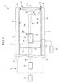
Fig. 1 is a diagram depicting a scanning observation apparatus according to a first embodiment of the present invention. - {
Fig. 2 }
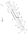
Fig. 2 is a perspective view of a scanner according to the first embodiment of the present invention provided in the scanning illuminator ofFig. 1 . - {
Fig. 3 }
Fig. 3 is a cross-section of a drive unit, as viewed from the exit end of an optical fiber, before a correction portion of the scanner according to the first embodiment of the present invention is provided. - {
Fig. 4 }
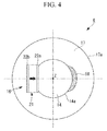
Fig. 4 is a cross-section of the drive unit, as viewed from the exit end of the optical fiber, after the correction portion of the scanner according to the first embodiment of the present invention has been provided. - {
Fig. 5 }
Fig. 5 is a perspective view of a scanner according to a second embodiment of the present invention. - {
Fig. 6 }
Fig. 6 is a cross-section of a drive unit, as viewed from the exit end of an optical fiber, before a correction portion of the scanner according to the second embodiment of the present invention is provided. - {
Fig. 7 }
Fig. 7 is a cross-section of the drive unit, as viewed from the exit end of the optical fiber, after the correction portion of the scanner according to the second embodiment of the present invention has been provided. - {
Fig. 8 }
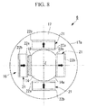
Fig. 8 is a cross-section of a drive unit of a scanner according to a modification of the first embodiment of the present invention, as viewed from the exit end of an optical fiber. - {
Fig. 9 }
Fig. 9 is a cross-section of a drive unit of a scanner according to a modification of the second embodiment of the present invention, as viewed from the exit end of an optical fiber. - A scanner, a scanning illuminator, and a scanning observation apparatus according to a first embodiment of the present invention will now be described with reference to the drawings.
- As shown in
Fig. 1 , a scanning observation apparatus 1 according to this embodiment includes: a cylindrical apparatusmain body 4; ascanning illuminator 2 that is accommodated inside the apparatusmain body 4 and irradiates a surface of an irradiated subject P with illumination light; and a light detection unit 3 that receives return light (e.g., reflected light, fluorescence) from the irradiated subject P, namely, return light of the illumination light radiated from thescanning illuminator 2 onto the surface of the irradiated subject P, and that detects the intensity of the return light. - As shown in
Fig. 1 , thescanning illuminator 2 includes: alight source 10 that generates illumination light; ascanner 6 according to this embodiment that one-dimensionally scans the illumination light emitted from thelight source 10; a light-focusinglens 11 that focuses the illumination light; and acontrol unit 13 that controls thescanner 6. - As shown in
Figs. 2 and4 , thescanner 6 according to this embodiment includes: anoptical fiber 14 that guides the illumination light emitted from thelight source 10; adrive unit 16 that scans the illumination light emitted from anexit end 15 of theoptical fiber 14; asupport portion 17 that supports theoptical fiber 14; and acorrection portion 18 that corrects the center of gravity of thedrive unit 16. - As shown in
Fig. 2 , theoptical fiber 14 has aflat surface section 20 composed of a flat surface substantially parallel to an optical axis S such that theflat surface section 20 is formed in a part of anouter surface 14a in the circumferential direction. - As shown in
Figs. 2 and4 , thedrive unit 16 includes: asingle actuator 21 fixed to theflat surface section 20; theoptical fiber 14 serving as a section to which theactuator 21 is fixed; and acorrection portion 18. - The
actuator 21 is electromagnetic or piezoelectric and includeselectrodes electrodes actuator 21 produces an oscillation with a direction and an amplitude based on the applied voltage signal. Because theactuator 21 is fixed to theoptical fiber 14 with theelectrode 22a in contact with theflat surface section 20, theactuator 21 can propagate its oscillation to theoptical fiber 14 so as to oscillate theexit end 15 of theoptical fiber 14 in one axial direction orthogonal to theflat surface section 20. - As shown in
Figs. 1 and2 , thesupport portion 17 is a ring-shaped member that is provided away from thedrive unit 16 towards the longitudinal basal end of the apparatusmain body 4 and that includes a through-hole 23 in the thickness direction thereof along the longitudinal axis of the apparatusmain body 4. Theoptical fiber 14 is fixed in thesupport portion 17 so as to penetrate the through-hole 23, and anouter surface 17a of thesupport portion 17 is in close contact with aninner surface 4b of the apparatusmain body 4. - Furthermore, the
support portion 17 fixes theoptical fiber 14 to the apparatusmain body 4 at a position towards the basal end from thedrive unit 16 so that the oscillation propagated from thedrive unit 16 to theoptical fiber 14 can be inhibited from being propagated towards the basal end beyond thesupport portion 17. - As shown in
Figs. 2 and4 , thecorrection portion 18 is an adhesive. Thecorrection portion 18 is fixed to part of theoptical fiber 14 and adjusts a center of gravity Y of thescanner 6 on a cross-section of thedrive unit 16 to a center of gravity Z, shown inFig. 4 , at which the two centers of gravity X and Y shown inFig. 3 coincide with each other. - As shown in
Fig. 1 , the light-focusinglens 11 is held at alens support portion 12, which is provided on theinner surface 4b of the apparatusmain body 4 and closer to the distal end side than thescanner 6 is, and converges illumination light scanned by thescanner 6 onto the surface of the irradiated subject P. - As shown in
Fig. 1 , thecontrol unit 13 supplies a voltage signal based on a predetermined scanning trajectory to theactuator 21 such that the illumination light emitted from the exit end 15 of theoptical fiber 14 forms a predetermined scanning trajectory input by the user. - As shown in
Fig. 1 , the light detection unit 3 includes detectingoptical fibers 7 that receive return light from the irradiated subject P and guide it to the basal end side of the apparatusmain body 4 and asensor 31 that detects the intensity of the return light guided by the detectingoptical fibers 7. - As shown in
Fig. 1 , the plurality of detectingoptical fibers 7 extend along a longitudinal direction and are arranged in a circumferential direction on the outercircumferential surface 4a of the apparatusmain body 4, with the light-entrance ends 8 oriented towards the front. - The
sensor 31 receives the return light guided by these detectingoptical fibers 7 simultaneously to detect the total intensity of the return light. - The operation of the scanning observation apparatus 1 with the above-described structure according to this embodiment will now be described.
- When a voltage signal is supplied from the
control unit 13 to theelectrodes actuator 21, theactuator 21 is oscillated in a manner corresponding to the supplied voltage signal, and that oscillation is propagated from theactuator 21 to theoptical fiber 14. When the oscillation is propagated to theoptical fiber 14, the exit end 15 of theoptical fiber 14 is greatly oscillated in one axial direction due to resonance. When the illumination light that has been guided through theoptical fiber 14 is emitted from theexit end 15 in a state where theexit end 15 is greatly oscillated in one axial direction, the illumination light can be oscillated in a direction intersecting the optical axis S of theoptical fiber 14 so as to scan the surface of the irradiated subject P. - In other words, according to the scanning observation apparatus 1 of this embodiment, illumination light that has been emitted from the
light source 10 of thescanning illuminator 2 and has exited from the exit end 15 of theoptical fiber 14 is scanned by thescanner 6 in a direction intersecting the optical axis S, is focused by the light-focusinglens 11, and is radiated onto the surface of the irradiated subject P as a spot of light. - Thereafter, the return light from the irradiated subject P as a result of being irradiated with the illumination light is incident upon the light-entrance ends 8 of the detecting
optical fibers 7 and is received by thesensor 31 through the detectingoptical fibers 7. By doing so, each of the scanning positions of theoptical fiber 14 scanned by thescanner 6 is associated with the intensity of return light received by thesensor 31, thereby allowing an image of a strain-free return light distribution to be generated. - In this case, because the center of gravity Y of the
scanner 6 is corrected by thecorrection portion 18 provided on thedrive unit 16 so as to coincide with the center of gravity X of thedrive unit 16, as shown inFig. 4 , an advantage is afforded in that a desired scanning trajectory faithfully reflecting the applied voltage signal can be achieved with high accuracy in the form of a scanning trajectory of the exit end 15 of theoptical fiber 14. - According to the
scanner 6 of this embodiment, because theactuator 21 is fixed to theflat surface section 20 of theoptical fiber 14, theactuator 21 and theouter surface 14a of theoptical fiber 14 are in stable contact with each other via a large region of the contacting surface. By doing so, displacement of theactuator 21 and theoptical fiber 14 relative to each other when oscillation is propagated from theactuator 21 to theoptical fiber 14 is controlled, and propagation of the oscillation in a desired direction can be efficiently performed. - This embodiment has been described by way of example of the
optical fiber 14 including theflat surface section 20 but is not limited to this as long as the optical fiber guides the illumination light. - This embodiment has been described by way of example of the
correction portion 18 as an adhesive but is not limited to this. Any member, such as resin or metal member, may be fixed with an adhesive. - For the
correction portion 18, not only members that completely match the two centers of gravity X and Y, but also members that bring the two centers of gravity X and Y close to each other are also acceptable. - A
scanner 24, a scanning illuminator 25 (not shown in the drawings), and a scanning observation apparatus 26 (not shown in the drawings) according to a second embodiment of the present invention will now be described with reference to the drawings. - In describing this embodiment, components with the same structures as those of components used in the
scanner 6, thescanning illuminator 2, and the scanning observation apparatus 1 according to the first embodiment are denoted by the same reference signs, and thus will not be described. - As shown in
Figs. 5 and7 , in thescanner 24 according to this embodiment, adrive unit 27 includes a rectangular tubularoscillation propagation member 29 having an axial through-hole 28 through which theoptical fiber 14 passes. Thescanner 24 differs from thescanner 6 according to the first embodiment in that theactuators 21 are fixed to two respectiveouter surfaces 29a adjacent to each other in the circumferential direction of theoscillation propagation member 29. - The
actuators 21 fixed to the neighboringouter surfaces 29a of the rectangular tubularoscillation propagation member 29 are arranged with their oscillation directions being shifted by substantially 90°. - As shown in
Fig. 7 , acorrection portion 30 is made of an adhesive fixed to anouter surface 29a and/or aninner surface 29b of theoscillation propagation member 29. Thecorrection portion 30 adjusts the center of gravity K of thescanner 24 and the center of gravity L of thedrive unit 27 shown inFig. 6 , on a cross-section of thedrive unit 27, so that the two centers of gravity K and L are corrected to be the center of gravity Q, where the positions K and L coincide with each other. - The operation of the
scanner 24, the scanning illuminator 25 (not shown in the figure), and the scanning observation apparatus 26 (not shown in the figure) according to this embodiment with the above-described structure will now be described. - When a voltage signal is supplied to each of the
electrodes actuators 21 from thecontrol unit 13, the exit end 15 of theoptical fiber 14 can be displaced in two axial directions substantially orthogonal to each other. - Then, by adjusting the amplitude and phase of the voltage signal supplied to each of the
electrodes actuators 21, the exit end 15 of theoptical fiber 14 can be displaced two-dimensionally along an arbitrary trajectory. By doing so, the illumination light emitted from the exit end 15 of theoptical fiber 14 can be scanned two-dimensionally. - For example, by supplying the two
actuators 21 with voltage signals that are sine waves having linearly decreasing amplitudes and phases shifted by 90° relative to each other, illumination light in a helical shape can be radiated onto the surface of the irradiated subject P. - In this case, according to the
scanner 24 of this embodiment, because the center of gravity L of thedrive unit 27 is adjusted by thecorrection portion 30, illumination light can be radiated onto a position corresponding to the voltage signal with high accuracy. As a result, an advantage is afforded in that the scanning position of the illumination light corresponding to the voltage signal can be made to highly accurately coincide with an actual radiation position of the illumination light, thereby making it possible to generate a strain-free return light image on the basis of information about the scanning position and the intensity of return light detected by thesensor 31. - Also in this embodiment, because each of the
actuators 21 is stably fixed to theouter surfaces 29a on a flat surface of theoscillation propagation member 29, displacement of theactuators 21 relative to theoscillation propagation member 29 can be controlled, thereby efficiently oscillating theoptical fiber 14 held in the through-hole 28. - As shown in
Figs. 8 and9 , in thescanners drive units actuators 21 that provide oscillation in the radial direction of theoptical fiber 14, so that theactuators 21 may be disposed adjacent to one another and spaced apart from one another at substantially 90° intervals in the circumferential direction of theoptical fiber 14. In addition, threeactuators 21 or five ormore actuators 21 may be provided. -
- 1
- Scanning observation apparatus
- 2
- Scanning illuminator
- 3
- Light detection unit
- 6, 24
- Scanner
- 10
- Light source
- 11
- Light-focusing lens
- 14
- Optical fiber
- 14a
- Outer surface of optical fiber
- 15
- Exit end of optical fiber
- 16, 27
- Drive unit
- 17
- Support portion
- 18, 30
- Correction portion
- 20
- Flat surface section
- 21
- Actuator
- 28
- Through-hole of oscillation propagation member
- 29
- Oscillation propagation member
Claims (7)
- A scanner comprising:an optical fiber that guides light from a light source;a drive unit including at least one actuator that, when a voltage is applied thereto, displaces an exit end of the optical fiber in a direction intersecting an optical axis;a support portion that is provided on a basal end side from the drive unit and that is spaced from the drive unit to support the optical fiber; anda correction portion that performs correction so as to bring the center of gravity of the drive unit and a combined center of gravity of the optical fiber, the drive unit, and the support portion close to each other on a cross-section of the drive unit.
- The scanner according to claim 1,
wherein the drive unit is fixed to a flat surface section that is formed in a part of an outer surface of at least the optical fiber and that is substantially parallel to the optical axis. - The scanner according to claim 1 or 2,
wherein the drive unit includes a polygonal tubular oscillation propagation member that has a through-hole in an axial direction thereof and that is composed of a material capable of propagating oscillation, the optical fiber passes through the through-hole of the oscillation propagation member, and the actuator is fixed to the outer surface of the oscillation propagation member. - The scanner according to one of claims 1 to 3,
wherein the actuator displaces the exit end of the optical fiber in one axial direction. - The scanner according to claim 4,
wherein the drive unit includes at least two of the actuators, which produces oscillations in a radial direction of the optical fiber, and
the actuators adjacent to each other in a circumferential direction are arranged so as to be spaced apart by substantially 90° in a circumferential direction of the optical fiber. - A scanning illuminator comprising:a light source that generates light to be guided to the optical fiber;the scanner according to one of claims 1 to 5; anda light-focusing lens that focuses light scanned by the scanner onto an irradiated subject.
- A scanning observation apparatus comprising:the scanning illuminator according to claim 6; anda light detection unit that receives return light of light radiated from the scanning illuminator onto an irradiated subject and detects the intensity of the return light.
Applications Claiming Priority (2)
| Application Number | Priority Date | Filing Date | Title |
|---|---|---|---|
| JP2013218227A JP6321939B2 (en) | 2013-10-21 | 2013-10-21 | Scanner, scanning illumination device, and scanning observation device |
| PCT/JP2014/075733 WO2015060067A1 (en) | 2013-10-21 | 2014-09-26 | Scanner, scanning-type lighting apparatus, and scanning-type observation apparatus |
Publications (3)
| Publication Number | Publication Date |
|---|---|
| EP3062138A1 true EP3062138A1 (en) | 2016-08-31 |
| EP3062138A4 EP3062138A4 (en) | 2017-05-17 |
| EP3062138B1 EP3062138B1 (en) | 2018-06-06 |
Family
ID=52992670
Family Applications (1)
| Application Number | Title | Priority Date | Filing Date |
|---|---|---|---|
| EP14855352.2A Not-in-force EP3062138B1 (en) | 2013-10-21 | 2014-09-26 | Scanner, scanning-type lighting apparatus, and scanning-type observation apparatus |
Country Status (5)
| Country | Link |
|---|---|
| US (1) | US10151918B2 (en) |
| EP (1) | EP3062138B1 (en) |
| JP (1) | JP6321939B2 (en) |
| CN (1) | CN105637406B (en) |
| WO (1) | WO2015060067A1 (en) |
Cited By (2)
| Publication number | Priority date | Publication date | Assignee | Title |
|---|---|---|---|---|
| US20210191108A1 (en) * | 2018-06-26 | 2021-06-24 | Magic Leap, Inc. | Hybrid optical fiber mems scanner |
| US11899197B2 (en) | 2018-06-26 | 2024-02-13 | Magic Leap, Inc. | Raster scanned projector with microelectromechanical system scanner |
Families Citing this family (6)
| Publication number | Priority date | Publication date | Assignee | Title |
|---|---|---|---|---|
| DE102016011647A1 (en) | 2016-09-26 | 2018-03-29 | Blickfeld GmbH | Excitation of fibers with bending piezoactuators |
| WO2018061525A1 (en) | 2016-09-30 | 2018-04-05 | 東レ株式会社 | Negative photosensitive resin composition, cured film, element provided with cured film, display device provided with cured film and method for producing same |
| WO2018139514A1 (en) * | 2017-01-27 | 2018-08-02 | オリンパス株式会社 | Optical scanning-type observation probe and optical scanning-type observation device |
| CN111258057A (en) * | 2018-11-30 | 2020-06-09 | 成都理想境界科技有限公司 | Scanning driver and optical fiber scanner |
| CN112305754B (en) * | 2019-07-26 | 2023-07-07 | 成都理想境界科技有限公司 | Scanning actuator, optical fiber scanning device and scanning display equipment |
| JP7585459B2 (en) * | 2020-08-13 | 2024-11-18 | アースレックス インコーポレイテッド | Endoscopic Instruments |
Family Cites Families (6)
| Publication number | Priority date | Publication date | Assignee | Title |
|---|---|---|---|---|
| US7616986B2 (en) * | 2001-05-07 | 2009-11-10 | University Of Washington | Optical fiber scanner for performing multimodal optical imaging |
| EP1592992B1 (en) * | 2003-01-24 | 2012-05-30 | University of Washington | Optical beam scanning system for compact image display or image acquisition |
| DE112005002322B4 (en) * | 2004-09-24 | 2021-04-22 | Hoya Corp. | Scanning device, optical head, optical instrument and scanning method |
| JP5210894B2 (en) * | 2009-01-13 | 2013-06-12 | Hoya株式会社 | Optical scanning endoscope |
| JP2012229976A (en) | 2011-04-26 | 2012-11-22 | Hoya Corp | Optical scanning probe |
| CN105852787B (en) | 2011-11-09 | 2018-01-23 | 奥林巴斯株式会社 | Endoscope apparatus |
-
2013
- 2013-10-21 JP JP2013218227A patent/JP6321939B2/en active Active
-
2014
- 2014-09-26 EP EP14855352.2A patent/EP3062138B1/en not_active Not-in-force
- 2014-09-26 WO PCT/JP2014/075733 patent/WO2015060067A1/en not_active Ceased
- 2014-09-26 CN CN201480057265.3A patent/CN105637406B/en active Active
-
2016
- 2016-04-15 US US15/130,141 patent/US10151918B2/en active Active
Cited By (3)
| Publication number | Priority date | Publication date | Assignee | Title |
|---|---|---|---|---|
| US20210191108A1 (en) * | 2018-06-26 | 2021-06-24 | Magic Leap, Inc. | Hybrid optical fiber mems scanner |
| US11899197B2 (en) | 2018-06-26 | 2024-02-13 | Magic Leap, Inc. | Raster scanned projector with microelectromechanical system scanner |
| US12117609B2 (en) * | 2018-06-26 | 2024-10-15 | Magic Leap, Inc. | Hybrid optical fiber MEMS scanner |
Also Published As
| Publication number | Publication date |
|---|---|
| US20160231561A1 (en) | 2016-08-11 |
| CN105637406A (en) | 2016-06-01 |
| CN105637406B (en) | 2018-06-15 |
| JP2015081935A (en) | 2015-04-27 |
| JP6321939B2 (en) | 2018-05-09 |
| EP3062138A4 (en) | 2017-05-17 |
| WO2015060067A1 (en) | 2015-04-30 |
| EP3062138B1 (en) | 2018-06-06 |
| US10151918B2 (en) | 2018-12-11 |
Similar Documents
| Publication | Publication Date | Title |
|---|---|---|
| EP3062138B1 (en) | Scanner, scanning-type lighting apparatus, and scanning-type observation apparatus | |
| CN105188502B (en) | Fiber optic scanner, lighting device and observation device | |
| US10330916B2 (en) | Optical-fiber scanner, illumination apparatus, and observation apparatus | |
| CN106132268B (en) | Fibre optic scanner, lighting device and observation device | |
| US9874739B2 (en) | Optical fiber scanner, illumination apparatus, and observation apparatus | |
| US10534168B2 (en) | Light-scanning apparatus and light-scanning-apparatus control method | |
| US20170090181A1 (en) | Optical scanning endoscope apparatus | |
| JP2012231911A (en) | Optical scanner and scan type observation device | |
| JP5745922B2 (en) | Optical scanning observation device | |
| US20180252910A1 (en) | Optical fiber scanner, illumination device, and observation device | |
| JP6401382B2 (en) | Optical fiber scanner and scanning observation apparatus | |
| JPWO2016116962A1 (en) | Optical scanning method and optical scanning device | |
| US10356287B2 (en) | Optical scanning apparatus and method of controlling optical scanning apparatus | |
| US20190235231A1 (en) | Optical fiber scanner, illumination device, and observation device | |
| JPWO2016189627A1 (en) | Optical fiber scanner, illumination device and observation device | |
| WO2020021658A1 (en) | Light projection device and light projection method | |
| JPWO2017068924A1 (en) | Optical fiber scanner, illumination device and observation device | |
| JPWO2017068651A1 (en) | Optical fiber scanner, illumination device and observation device | |
| WO2020021659A1 (en) | Light projection device and light projection method |
Legal Events
| Date | Code | Title | Description |
|---|---|---|---|
| PUAI | Public reference made under article 153(3) epc to a published international application that has entered the european phase |
Free format text: ORIGINAL CODE: 0009012 |
|
| 17P | Request for examination filed |
Effective date: 20160429 |
|
| AK | Designated contracting states |
Kind code of ref document: A1 Designated state(s): AL AT BE BG CH CY CZ DE DK EE ES FI FR GB GR HR HU IE IS IT LI LT LU LV MC MK MT NL NO PL PT RO RS SE SI SK SM TR |
|
| AX | Request for extension of the european patent |
Extension state: BA ME |
|
| RAP1 | Party data changed (applicant data changed or rights of an application transferred) |
Owner name: OLYMPUS CORPORATION |
|
| RAP1 | Party data changed (applicant data changed or rights of an application transferred) |
Owner name: OLYMPUS CORPORATION |
|
| DAX | Request for extension of the european patent (deleted) | ||
| A4 | Supplementary search report drawn up and despatched |
Effective date: 20170421 |
|
| RIC1 | Information provided on ipc code assigned before grant |
Ipc: A61B 1/00 20060101ALI20170413BHEP Ipc: A61B 1/07 20060101ALI20170413BHEP Ipc: G02B 23/26 20060101ALI20170413BHEP Ipc: A61B 1/06 20060101ALI20170413BHEP Ipc: G02B 23/24 20060101ALI20170413BHEP Ipc: G02B 26/10 20060101AFI20170413BHEP |
|
| GRAP | Despatch of communication of intention to grant a patent |
Free format text: ORIGINAL CODE: EPIDOSNIGR1 |
|
| STAA | Information on the status of an ep patent application or granted ep patent |
Free format text: STATUS: GRANT OF PATENT IS INTENDED |
|
| INTG | Intention to grant announced |
Effective date: 20180108 |
|
| RIN1 | Information on inventor provided before grant (corrected) |
Inventor name: KASAI, YASUAKI Inventor name: TSURUTA, HIROSHI |
|
| GRAS | Grant fee paid |
Free format text: ORIGINAL CODE: EPIDOSNIGR3 |
|
| GRAA | (expected) grant |
Free format text: ORIGINAL CODE: 0009210 |
|
| STAA | Information on the status of an ep patent application or granted ep patent |
Free format text: STATUS: THE PATENT HAS BEEN GRANTED |
|
| AK | Designated contracting states |
Kind code of ref document: B1 Designated state(s): AL AT BE BG CH CY CZ DE DK EE ES FI FR GB GR HR HU IE IS IT LI LT LU LV MC MK MT NL NO PL PT RO RS SE SI SK SM TR |
|
| REG | Reference to a national code |
Ref country code: GB Ref legal event code: FG4D |
|
| REG | Reference to a national code |
Ref country code: CH Ref legal event code: EP Ref country code: AT Ref legal event code: REF Ref document number: 1006736 Country of ref document: AT Kind code of ref document: T Effective date: 20180615 |
|
| REG | Reference to a national code |
Ref country code: IE Ref legal event code: FG4D |
|
| REG | Reference to a national code |
Ref country code: DE Ref legal event code: R096 Ref document number: 602014026812 Country of ref document: DE |
|
| REG | Reference to a national code |
Ref country code: NL Ref legal event code: MP Effective date: 20180606 |
|
| REG | Reference to a national code |
Ref country code: LT Ref legal event code: MG4D |
|
| PG25 | Lapsed in a contracting state [announced via postgrant information from national office to epo] |
Ref country code: BG Free format text: LAPSE BECAUSE OF FAILURE TO SUBMIT A TRANSLATION OF THE DESCRIPTION OR TO PAY THE FEE WITHIN THE PRESCRIBED TIME-LIMIT Effective date: 20180906 Ref country code: FI Free format text: LAPSE BECAUSE OF FAILURE TO SUBMIT A TRANSLATION OF THE DESCRIPTION OR TO PAY THE FEE WITHIN THE PRESCRIBED TIME-LIMIT Effective date: 20180606 Ref country code: NO Free format text: LAPSE BECAUSE OF FAILURE TO SUBMIT A TRANSLATION OF THE DESCRIPTION OR TO PAY THE FEE WITHIN THE PRESCRIBED TIME-LIMIT Effective date: 20180906 Ref country code: SE Free format text: LAPSE BECAUSE OF FAILURE TO SUBMIT A TRANSLATION OF THE DESCRIPTION OR TO PAY THE FEE WITHIN THE PRESCRIBED TIME-LIMIT Effective date: 20180606 Ref country code: LT Free format text: LAPSE BECAUSE OF FAILURE TO SUBMIT A TRANSLATION OF THE DESCRIPTION OR TO PAY THE FEE WITHIN THE PRESCRIBED TIME-LIMIT Effective date: 20180606 Ref country code: ES Free format text: LAPSE BECAUSE OF FAILURE TO SUBMIT A TRANSLATION OF THE DESCRIPTION OR TO PAY THE FEE WITHIN THE PRESCRIBED TIME-LIMIT Effective date: 20180606 Ref country code: CY Free format text: LAPSE BECAUSE OF FAILURE TO SUBMIT A TRANSLATION OF THE DESCRIPTION OR TO PAY THE FEE WITHIN THE PRESCRIBED TIME-LIMIT Effective date: 20180606 |
|
| PG25 | Lapsed in a contracting state [announced via postgrant information from national office to epo] |
Ref country code: RS Free format text: LAPSE BECAUSE OF FAILURE TO SUBMIT A TRANSLATION OF THE DESCRIPTION OR TO PAY THE FEE WITHIN THE PRESCRIBED TIME-LIMIT Effective date: 20180606 Ref country code: HR Free format text: LAPSE BECAUSE OF FAILURE TO SUBMIT A TRANSLATION OF THE DESCRIPTION OR TO PAY THE FEE WITHIN THE PRESCRIBED TIME-LIMIT Effective date: 20180606 Ref country code: LV Free format text: LAPSE BECAUSE OF FAILURE TO SUBMIT A TRANSLATION OF THE DESCRIPTION OR TO PAY THE FEE WITHIN THE PRESCRIBED TIME-LIMIT Effective date: 20180606 Ref country code: GR Free format text: LAPSE BECAUSE OF FAILURE TO SUBMIT A TRANSLATION OF THE DESCRIPTION OR TO PAY THE FEE WITHIN THE PRESCRIBED TIME-LIMIT Effective date: 20180907 |
|
| REG | Reference to a national code |
Ref country code: AT Ref legal event code: MK05 Ref document number: 1006736 Country of ref document: AT Kind code of ref document: T Effective date: 20180606 |
|
| PG25 | Lapsed in a contracting state [announced via postgrant information from national office to epo] |
Ref country code: NL Free format text: LAPSE BECAUSE OF FAILURE TO SUBMIT A TRANSLATION OF THE DESCRIPTION OR TO PAY THE FEE WITHIN THE PRESCRIBED TIME-LIMIT Effective date: 20180606 |
|
| PG25 | Lapsed in a contracting state [announced via postgrant information from national office to epo] |
Ref country code: SK Free format text: LAPSE BECAUSE OF FAILURE TO SUBMIT A TRANSLATION OF THE DESCRIPTION OR TO PAY THE FEE WITHIN THE PRESCRIBED TIME-LIMIT Effective date: 20180606 Ref country code: EE Free format text: LAPSE BECAUSE OF FAILURE TO SUBMIT A TRANSLATION OF THE DESCRIPTION OR TO PAY THE FEE WITHIN THE PRESCRIBED TIME-LIMIT Effective date: 20180606 Ref country code: AT Free format text: LAPSE BECAUSE OF FAILURE TO SUBMIT A TRANSLATION OF THE DESCRIPTION OR TO PAY THE FEE WITHIN THE PRESCRIBED TIME-LIMIT Effective date: 20180606 Ref country code: IS Free format text: LAPSE BECAUSE OF FAILURE TO SUBMIT A TRANSLATION OF THE DESCRIPTION OR TO PAY THE FEE WITHIN THE PRESCRIBED TIME-LIMIT Effective date: 20181006 Ref country code: RO Free format text: LAPSE BECAUSE OF FAILURE TO SUBMIT A TRANSLATION OF THE DESCRIPTION OR TO PAY THE FEE WITHIN THE PRESCRIBED TIME-LIMIT Effective date: 20180606 Ref country code: PL Free format text: LAPSE BECAUSE OF FAILURE TO SUBMIT A TRANSLATION OF THE DESCRIPTION OR TO PAY THE FEE WITHIN THE PRESCRIBED TIME-LIMIT Effective date: 20180606 Ref country code: CZ Free format text: LAPSE BECAUSE OF FAILURE TO SUBMIT A TRANSLATION OF THE DESCRIPTION OR TO PAY THE FEE WITHIN THE PRESCRIBED TIME-LIMIT Effective date: 20180606 |
|
| PGFP | Annual fee paid to national office [announced via postgrant information from national office to epo] |
Ref country code: DE Payment date: 20180927 Year of fee payment: 5 |
|
| PG25 | Lapsed in a contracting state [announced via postgrant information from national office to epo] |
Ref country code: SM Free format text: LAPSE BECAUSE OF FAILURE TO SUBMIT A TRANSLATION OF THE DESCRIPTION OR TO PAY THE FEE WITHIN THE PRESCRIBED TIME-LIMIT Effective date: 20180606 Ref country code: IT Free format text: LAPSE BECAUSE OF FAILURE TO SUBMIT A TRANSLATION OF THE DESCRIPTION OR TO PAY THE FEE WITHIN THE PRESCRIBED TIME-LIMIT Effective date: 20180606 |
|
| REG | Reference to a national code |
Ref country code: DE Ref legal event code: R097 Ref document number: 602014026812 Country of ref document: DE |
|
| PLBE | No opposition filed within time limit |
Free format text: ORIGINAL CODE: 0009261 |
|
| STAA | Information on the status of an ep patent application or granted ep patent |
Free format text: STATUS: NO OPPOSITION FILED WITHIN TIME LIMIT |
|
| PG25 | Lapsed in a contracting state [announced via postgrant information from national office to epo] |
Ref country code: MC Free format text: LAPSE BECAUSE OF FAILURE TO SUBMIT A TRANSLATION OF THE DESCRIPTION OR TO PAY THE FEE WITHIN THE PRESCRIBED TIME-LIMIT Effective date: 20180606 |
|
| REG | Reference to a national code |
Ref country code: CH Ref legal event code: PL |
|
| 26N | No opposition filed |
Effective date: 20190307 |
|
| GBPC | Gb: european patent ceased through non-payment of renewal fee |
Effective date: 20180926 |
|
| PG25 | Lapsed in a contracting state [announced via postgrant information from national office to epo] |
Ref country code: DK Free format text: LAPSE BECAUSE OF FAILURE TO SUBMIT A TRANSLATION OF THE DESCRIPTION OR TO PAY THE FEE WITHIN THE PRESCRIBED TIME-LIMIT Effective date: 20180606 Ref country code: SI Free format text: LAPSE BECAUSE OF FAILURE TO SUBMIT A TRANSLATION OF THE DESCRIPTION OR TO PAY THE FEE WITHIN THE PRESCRIBED TIME-LIMIT Effective date: 20180606 |
|
| REG | Reference to a national code |
Ref country code: BE Ref legal event code: MM Effective date: 20180930 |
|
| REG | Reference to a national code |
Ref country code: IE Ref legal event code: MM4A |
|
| PG25 | Lapsed in a contracting state [announced via postgrant information from national office to epo] |
Ref country code: LU Free format text: LAPSE BECAUSE OF NON-PAYMENT OF DUE FEES Effective date: 20180926 |
|
| PG25 | Lapsed in a contracting state [announced via postgrant information from national office to epo] |
Ref country code: IE Free format text: LAPSE BECAUSE OF NON-PAYMENT OF DUE FEES Effective date: 20180926 |
|
| PG25 | Lapsed in a contracting state [announced via postgrant information from national office to epo] |
Ref country code: BE Free format text: LAPSE BECAUSE OF NON-PAYMENT OF DUE FEES Effective date: 20180930 Ref country code: LI Free format text: LAPSE BECAUSE OF NON-PAYMENT OF DUE FEES Effective date: 20180930 Ref country code: FR Free format text: LAPSE BECAUSE OF NON-PAYMENT OF DUE FEES Effective date: 20180930 Ref country code: CH Free format text: LAPSE BECAUSE OF NON-PAYMENT OF DUE FEES Effective date: 20180930 |
|
| PG25 | Lapsed in a contracting state [announced via postgrant information from national office to epo] |
Ref country code: GB Free format text: LAPSE BECAUSE OF NON-PAYMENT OF DUE FEES Effective date: 20180926 |
|
| PG25 | Lapsed in a contracting state [announced via postgrant information from national office to epo] |
Ref country code: AL Free format text: LAPSE BECAUSE OF FAILURE TO SUBMIT A TRANSLATION OF THE DESCRIPTION OR TO PAY THE FEE WITHIN THE PRESCRIBED TIME-LIMIT Effective date: 20180606 |
|
| PG25 | Lapsed in a contracting state [announced via postgrant information from national office to epo] |
Ref country code: MT Free format text: LAPSE BECAUSE OF NON-PAYMENT OF DUE FEES Effective date: 20180926 |
|
| PG25 | Lapsed in a contracting state [announced via postgrant information from national office to epo] |
Ref country code: TR Free format text: LAPSE BECAUSE OF FAILURE TO SUBMIT A TRANSLATION OF THE DESCRIPTION OR TO PAY THE FEE WITHIN THE PRESCRIBED TIME-LIMIT Effective date: 20180606 |
|
| REG | Reference to a national code |
Ref country code: DE Ref legal event code: R119 Ref document number: 602014026812 Country of ref document: DE |
|
| PG25 | Lapsed in a contracting state [announced via postgrant information from national office to epo] |
Ref country code: PT Free format text: LAPSE BECAUSE OF FAILURE TO SUBMIT A TRANSLATION OF THE DESCRIPTION OR TO PAY THE FEE WITHIN THE PRESCRIBED TIME-LIMIT Effective date: 20180606 |
|
| PG25 | Lapsed in a contracting state [announced via postgrant information from national office to epo] |
Ref country code: HU Free format text: LAPSE BECAUSE OF FAILURE TO SUBMIT A TRANSLATION OF THE DESCRIPTION OR TO PAY THE FEE WITHIN THE PRESCRIBED TIME-LIMIT; INVALID AB INITIO Effective date: 20140926 Ref country code: MK Free format text: LAPSE BECAUSE OF NON-PAYMENT OF DUE FEES Effective date: 20180606 |
|
| PG25 | Lapsed in a contracting state [announced via postgrant information from national office to epo] |
Ref country code: DE Free format text: LAPSE BECAUSE OF NON-PAYMENT OF DUE FEES Effective date: 20200401 |