EP3062082A1 - Preparation of sample for charged-particle microscopy - Google Patents
Preparation of sample for charged-particle microscopy Download PDFInfo
- Publication number
- EP3062082A1 EP3062082A1 EP15156546.2A EP15156546A EP3062082A1 EP 3062082 A1 EP3062082 A1 EP 3062082A1 EP 15156546 A EP15156546 A EP 15156546A EP 3062082 A1 EP3062082 A1 EP 3062082A1
- Authority
- EP
- European Patent Office
- Prior art keywords
- sample
- membrane
- sample holder
- aqueous liquid
- aperture
- Prior art date
- Legal status (The legal status is an assumption and is not a legal conclusion. Google has not performed a legal analysis and makes no representation as to the accuracy of the status listed.)
- Granted
Links
Images

Classifications
-
- G—PHYSICS
- G01—MEASURING; TESTING
- G01N—INVESTIGATING OR ANALYSING MATERIALS BY DETERMINING THEIR CHEMICAL OR PHYSICAL PROPERTIES
- G01N1/00—Sampling; Preparing specimens for investigation
- G01N1/28—Preparing specimens for investigation including physical details of (bio-)chemical methods covered elsewhere, e.g. G01N33/50, C12Q
- G01N1/2813—Producing thin layers of samples on a substrate, e.g. smearing, spinning-on
-
- H—ELECTRICITY
- H01—ELECTRIC ELEMENTS
- H01J—ELECTRIC DISCHARGE TUBES OR DISCHARGE LAMPS
- H01J37/00—Discharge tubes with provision for introducing objects or material to be exposed to the discharge, e.g. for the purpose of examination or processing thereof
- H01J37/26—Electron or ion microscopes; Electron or ion diffraction tubes
-
- G—PHYSICS
- G01—MEASURING; TESTING
- G01N—INVESTIGATING OR ANALYSING MATERIALS BY DETERMINING THEIR CHEMICAL OR PHYSICAL PROPERTIES
- G01N1/00—Sampling; Preparing specimens for investigation
- G01N1/28—Preparing specimens for investigation including physical details of (bio-)chemical methods covered elsewhere, e.g. G01N33/50, C12Q
- G01N1/42—Low-temperature sample treatment, e.g. cryofixation
-
- H—ELECTRICITY
- H01—ELECTRIC ELEMENTS
- H01J—ELECTRIC DISCHARGE TUBES OR DISCHARGE LAMPS
- H01J37/00—Discharge tubes with provision for introducing objects or material to be exposed to the discharge, e.g. for the purpose of examination or processing thereof
- H01J37/02—Details
- H01J37/20—Means for supporting or positioning the object or the material; Means for adjusting diaphragms or lenses associated with the support
-
- H—ELECTRICITY
- H01—ELECTRIC ELEMENTS
- H01J—ELECTRIC DISCHARGE TUBES OR DISCHARGE LAMPS
- H01J37/00—Discharge tubes with provision for introducing objects or material to be exposed to the discharge, e.g. for the purpose of examination or processing thereof
- H01J37/26—Electron or ion microscopes; Electron or ion diffraction tubes
- H01J37/28—Electron or ion microscopes; Electron or ion diffraction tubes with scanning beams
-
- H—ELECTRICITY
- H01—ELECTRIC ELEMENTS
- H01J—ELECTRIC DISCHARGE TUBES OR DISCHARGE LAMPS
- H01J2237/00—Discharge tubes exposing object to beam, e.g. for analysis treatment, etching, imaging
- H01J2237/002—Cooling arrangements
-
- H—ELECTRICITY
- H01—ELECTRIC ELEMENTS
- H01J—ELECTRIC DISCHARGE TUBES OR DISCHARGE LAMPS
- H01J2237/00—Discharge tubes exposing object to beam, e.g. for analysis treatment, etching, imaging
- H01J2237/20—Positioning, supporting, modifying or maintaining the physical state of objects being observed or treated
- H01J2237/2001—Maintaining constant desired temperature
-
- H—ELECTRICITY
- H01—ELECTRIC ELEMENTS
- H01J—ELECTRIC DISCHARGE TUBES OR DISCHARGE LAMPS
- H01J2237/00—Discharge tubes exposing object to beam, e.g. for analysis treatment, etching, imaging
- H01J2237/20—Positioning, supporting, modifying or maintaining the physical state of objects being observed or treated
- H01J2237/2002—Controlling environment of sample
-
- H—ELECTRICITY
- H01—ELECTRIC ELEMENTS
- H01J—ELECTRIC DISCHARGE TUBES OR DISCHARGE LAMPS
- H01J2237/00—Discharge tubes exposing object to beam, e.g. for analysis treatment, etching, imaging
- H01J2237/20—Positioning, supporting, modifying or maintaining the physical state of objects being observed or treated
- H01J2237/201—Positioning, supporting, modifying or maintaining the physical state of objects being observed or treated for mounting multiple objects
-
- H—ELECTRICITY
- H01—ELECTRIC ELEMENTS
- H01J—ELECTRIC DISCHARGE TUBES OR DISCHARGE LAMPS
- H01J2237/00—Discharge tubes exposing object to beam, e.g. for analysis treatment, etching, imaging
- H01J2237/20—Positioning, supporting, modifying or maintaining the physical state of objects being observed or treated
- H01J2237/208—Elements or methods for movement independent of sample stage for influencing or moving or contacting or transferring the sample or parts thereof, e.g. prober needles or transfer needles in FIB/SEM systems
Definitions
- the invention relates to a method of preparing a sample for study in a charged-particle microscope, comprising the following steps:
- the invention also relates to a method of examining a sample in a charged-particle microscope (CPM), which microscope comprises:
- a sample of a type as referred to above will be solidified / rapidly frozen / vitrified, e.g. by plunging it into a bath of cryogen, and then removing it from the bath and maintaining it at cryogenic temperatures during transport/storage.
- Charged particle microscopy is a well-known and increasingly important technique for imaging microscopic objects, particularly in the form of electron microscopy.
- the basic genus of electron microscope has undergone evolution into a number of well-known apparatus species, such as the Transmission Electron Microscope (TEM), Scanning Electron Microscope (SEM), and Scanning Transmission Electron Microscope (STEM), and also into various sub-species, such as so-called “dual-beam” tools (e.g. a FIB-SEM), which additionally employ a "machining" Focused Ion Beam (FIB), allowing supportive activities such as ion-beam milling or Ion-Beam-Induced Deposition (IBID), for example. More specifically:
- a Charged Particle Microscope will comprise at least the following components:
- this improved method should be more versatile and efficient than known methods, and that it should produce a better-quality sample than prior-art approaches.
- the inventive method is characterized in that, before removing said blotting sheet, said depositing step is performed in at least two different zones of the sample holder, whereby:
- said depositing step is performed using a dispensing device selected from the group comprising a contactless dispenser and a touch-off dispenser.
- a dispensing device selected from the group comprising a contactless dispenser and a touch-off dispenser.
- Such dispensers have the advantage of allowing (very) localized deposition of aqueous liquid, if desired, but they can also be used to deposit liquid on relatively large areas, e.g . by employing a scanning motion of their dispensing "head" relative to the sample holder. It should hereby be noted that:
- At least said depositing step is performed in a space (enclosure/chamber/room) having a relative humidity (RH) of at least 95%.
- RH relative humidity
- a relatively high aerial humidity helps to prevent drying out of the sample during sample preparation (prior to vitrification), particularly in a situation in which different zones of the sample holder are provided with different aqueous liquids - which typically consumes more time than deposition of just one type of aqueous liquid.
- Such relatively high RH levels - which may preferably exceed 95% - can, for example, be achieved/maintained using a humidifier.
- the blotting sheet is pre-wetted prior to said depositing step. It has already been stated above that, when the blotting sheet is moistened, its hydrophilicity helps draw the deposited aqueous liquid through the perforation(s) from the deposition side (backside). Instead of waiting for the blotting sheet to become moistened by the deposited aqueous liquid itself, one can "kick start" this process by pre-wetting the blotting sheet prior to the depositing step. Such pre-wetting can occur before or after placing the blotting sheet against the membrane; in the latter case, one could, for example, use a spray to moisten the exposed surface of the blotting sheet that points away from the membrane.
- Pre-wetting can occur with pure water, or with a water-based solution/suspension that does not have a detrimental effect on the aqueous liquid that will subsequently be deposited; in that respect, pre-wetting can, if desired, be performed with the same type of aqueous liquid as will subsequently be deposited. Pre-wetting the blotting sheet in this manner also helps to maintain an elevated RH in the vicinity of the sample holder (see previous paragraph).
- the blotting sheet can be removed ( e.g . peeled or slid) from the sample holder, leaving behind a thin film of aqueous liquid in the perforation(s) of the membrane.
- the sample holder (+ aqueous liquid sample(s) thereon) will then be plunge-cooled by dipping it into a cryogen such as liquid ethane (e.g . at a temperature in the range -160 °C to -183 °C).
- a cryogen such as liquid ethane (e.g . at a temperature in the range -160 °C to -183 °C).
- cryo-transfer holder suitable for use in this context is for example, contained in European Patent Application EP 14197422 (FNL1423) [incorporated herein by reference].
- a sample prepared according to the current invention can, in principle, also be investigated in apparatus other than a CPM, e.g . in an X-Ray diffractometer (for crystallography studies, for instance).
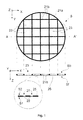
- FIG. 1 (not necessarily to scale) renders various views of aspects of a particular embodiment of a sample holder S that can be used in conjunction with the current invention
- This particular type of sample holder S comprises what is often referred to as a "grid” or “autogrid”. It comprises a circular ring 21a of Cu (or other metal) wire, the diameter of the ring being ca . 3 mm and the diameter of the wire being of the order of about 50-100 ⁇ m (typically).
- Located/attached within the ring 21 a are straight wire portions 21 b, which are arranged to form an orthogonal grid pattern, thus defining a matrix-like array of (substantially square) apertures (openings/holes/windows) 23.
- FIG. 1 shows a transverse cross-sectional view of the upper portion of the Figure, taken along the diameter A-A'. It shows that the sample holder S has a substantially planar (flat / plate-like) form, with opposed "front” (Sf) and “back” (Sb) faces substantially parallel to one another. Any given aperture 23 “connects" these faces Sb, Sf in that it acts as a connecting passage between them. As here depicted, a membrane 25 has been mounted (laid, stretched) upon the front face Sf (and, optionally, affixed to the wires 21b, e.g . using an adhesive or by molten bonding).
- This membrane 25 may, for example, comprise a carbonaceous material such as nylon or graphene, and will typically have a thickness (in the Z direction) ranging from about 0.3 nm to hundreds of nm.
- the membrane 25 contains a distribution of perforations 27, which are clearly visible in the detailed view at the bottom of the Figure. These perforations 27 typically have a diameter/width (parallel to the XY plane) of the order of about 2 ⁇ m. Note that the membrane 25 has:
- sample holders S as depicted in Figure 1 are commercially available, e.g . from firms such as Ted Pella, Inc., of Redding, California, USA. It is also possible to purchase (a variety of) pre-manufactured holey carbon films (corresponding to the perforated membrane 25, 27), e.g . from firms such as Quantifoil Micro Tools GmbH, Jena, Germany.
- a sample holder S for use in the current invention basically requires only one aperture 23 and only one perforation 27; however, a plurality of these structures 23, 27 is certainly allowed by the invention, and is generally advantageous in that it typically allows more sample material to be present on a given area of the sample holder S.
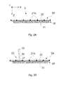
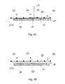
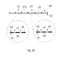
- FIGs. 2A-2E show a sample holder S such as that depicted in Figure 1 , during execution of various steps of an embodiment of a method according to the present invention. In particular, the following is depicted:
- Figure 3 is a highly schematic depiction of an embodiment a CPM in which the current invention can be applied; more specifically, it shows an embodiment of a transmission-type microscope M, which, in this case, is a TEM/STEM (though, in the context of the current invention, it could just as validly be an ion-based microscope, and/or a non-transmission type microscope such as a SEM, for example).
- a transmission-type microscope M which, in this case, is a TEM/STEM (though, in the context of the current invention, it could just as validly be an ion-based microscope, and/or a non-transmission type microscope such as a SEM, for example).
- an electron source 4 such as a Schottky emitter, for example
- This illuminator 6 has an electron-optical axis B', and will generally comprise a variety of electrostatic / magnetic lenses, (scan) deflector(s) D, correctors (such as stigmators), etc .; typically, it can also comprise a condenser system (in fact, the whole of item 6 is sometimes referred to as "a condenser system").
- the sample holder S is held on a (rod-like) supporting device H that seats into a cradle A' (such as the FEI CompuStage) connected to a positioning device (stage, actuator) A; this cradle A' can typically be moved/positioned in X, Y, Z, and can also often be rotated about X and/or Y (see the depicted Cartesian coordinate system).
- a positioning device stage, actuator
- Such positioning allows different parts of the sample holder S to be irradiated / imaged / inspected by the electron beam traveling along axis B', and also allows the sample holder S to be tilted as part of a tomographic measurement series (sinogram acquisition), for example; in principle, it also allows scanning motion to be performed, as an alternative to beam scanning.
- the (focused) electron beam B traveling along axis B' will interact with (specimens suspended in) film 29 (see Figures 1 , 2E ) on the sample holder S in such a manner as to cause various types of "stimulated" radiation flux to emanate from film 29, including (for example) secondary electrons, backscattered electrons, X-rays and optical radiation (cathodoluminescence). If desired, one or more of these radiation types can be detected using detector 22. However, in addition / alternatively, one can study electrons that traverse (pass through) the film 29, emerge (emanate) from it and continue to propagate (substantially, though generally with some deflection/scattering) along axis B'.
- Such a transmitted electron flux enters an imaging system (combined objective/projection lens) 24, which will generally comprise a variety of electrostatic / magnetic lenses, deflectors, correctors (such as stigmators), etc.
- this imaging system 24 can focus the transmitted electron flux onto a fluorescent screen 26, which, if desired, can be retracted/withdrawn (as schematically indicated by arrows 26') so as to get it out of the way of axis B'.
- An image (or diffractogram) of (part of) the (specimens suspended in) film 29 will be formed by imaging system 24 on screen 26, and this may be viewed through viewing port 28 located in a suitable part of a wall of enclosure E.
- the retraction mechanism for screen 26 may, for example, be mechanical and/or electrical in nature, and is not depicted here.
- controller C (computer processor) C (which may have a unitary or composite structure, as desired) is connected to various illustrated components via control lines (buses) C'.
- This controller C can provide a variety of functions, such as synchronizing actions, providing setpoints, processing signals, performing calculations, and displaying messages/information on a display device (not depicted).
- the interior of the enclosure E does not have to be kept at a strict vacuum; for example, in a so-called "Environmental TEM/STEM", a background atmosphere of a given gas is deliberately introduced/maintained within the enclosure E.
Landscapes
- Chemical & Material Sciences (AREA)
- Analytical Chemistry (AREA)
- Physics & Mathematics (AREA)
- Health & Medical Sciences (AREA)
- Life Sciences & Earth Sciences (AREA)
- Biochemistry (AREA)
- General Health & Medical Sciences (AREA)
- General Physics & Mathematics (AREA)
- Immunology (AREA)
- Pathology (AREA)
- Sampling And Sample Adjustment (AREA)
- Analysing Materials By The Use Of Radiation (AREA)
Abstract
- Providing a substantially planar sample holder having opposed faces substantially parallel to one another, comprising at least one aperture that connects said faces and across which a membrane has been mounted, which membrane comprises at least one perforation;
- Spanning a film of aqueous liquid across said perforation, which liquid comprises at least one study specimen suspended therein,
particularly comprising the following steps:
- Prior to said spanning step, placing a blotting sheet of blotting material in intimate contact with a first surface of said membrane, at a side distal from said sample holder;
- Depositing said aqueous liquid through said aperture and onto a second surface of said membrane, opposite said first surface;
- Subsequently removing said blotting sheet from said membrane.
Description
- The invention relates to a method of preparing a sample for study in a charged-particle microscope, comprising the following steps:
- Providing a substantially planar sample holder having opposed faces substantially parallel to one another, comprising at least one aperture that connects said faces and across which a membrane has been mounted, which membrane comprises at least one perforation;
- Spanning a film of aqueous liquid across said perforation, which liquid comprises at least one study specimen suspended therein.
- The invention also relates to a method of examining a sample in a charged-particle microscope (CPM), which microscope comprises:
- A supporting device, for supporting a sample holder on which the sample is mounted;
- A charged-particle source, for producing a beam of charged particles;
- An illuminator, for directing said beam so as to irradiate the sample;
- A detector, for detecting a flux of output radiation emanating from the sample in response to said irradiation.
- In general, after preparation and prior to examination in a CPM, a sample of a type as referred to above will be solidified / rapidly frozen / vitrified, e.g. by plunging it into a bath of cryogen, and then removing it from the bath and maintaining it at cryogenic temperatures during transport/storage.
- As used throughout this text, the ensuing terms should be interpreted consistent with the following explanation:
- The substantially planar sample holder may comprise more than one of the described apertures; in particular, it may be a grid-like structure that contains a matrix arrangement of such apertures. Similarly, the membrane spanned across a given aperture may contain more than one of the described perforations; in particular, it may comprise a (random or regular) distribution of such perforations. The perforations themselves may be deliberately created (e.g. using a boring, pricking, punching or etching technique), or they may be naturally present in the membrane. In the current context, the sample holder may be regarded as a "scaffolding" that serves to support the thin membrane mounted (stretched) thereon. Pre-manufactured, disposable, grid-like sample holders as described here are commercially available, e.g. in the form of so-called "TEM grids" or "autogrids". Similarly, perforated membranes are also commercially available, e.g. in the form of so-called "holey carbon" or Quantifoil® membranes.
- The phrase "aqueous liquid" is intended to encompass pure liquid water, but also water-based solutions or suspensions. The term therefore includes electrolytes, in addition to biological liquids such as cytoplasm, blood plasma, lymphatic fluid or amniotic fluid, for example. This aqueous liquid film is essentially "spanned" across said perforation(s) with the aid of surface tension effects.
- The term "cryogen" should be interpreted as referring to a liquid at cryogenic temperatures, i.e. at or below -150°C.
- The "sample" in the current case may be regarded as being said spanned film of (solidified/vitrified) aqueous liquid, including its suspended study specimen(s). In practice, a CPM study performed on such a sample will generally tend to concentrate on said specimen(s) rather than on the (solidified) liquid in which they are encapsulated.
- Charged particle microscopy is a well-known and increasingly important technique for imaging microscopic objects, particularly in the form of electron microscopy. Historically, the basic genus of electron microscope has undergone evolution into a number of well-known apparatus species, such as the Transmission Electron Microscope (TEM), Scanning Electron Microscope (SEM), and Scanning Transmission Electron Microscope (STEM), and also into various sub-species, such as so-called "dual-beam" tools (e.g. a FIB-SEM), which additionally employ a "machining" Focused Ion Beam (FIB), allowing supportive activities such as ion-beam milling or Ion-Beam-Induced Deposition (IBID), for example. More specifically:
- In a SEM, irradiation of a sample by a scanning electron beam precipitates emanation of "auxiliary" radiation from the sample, in the form of secondary electrons, backscattered electrons, X-rays and photoluminescence (infrared, visible and/or ultraviolet photons), for example; one or more components of this flux of emanating radiation is/are then detected and used for image accumulation purposes.
- In a TEM, the electron beam used to irradiate the sample is chosen to be of a high-enough energy to penetrate the sample (which, to this end, will generally be thinner than in the case of a SEM sample); the flux of transmitted electrons emanating from the sample can then be used to create an image. When such a TEM is operated in scanning mode (thus becoming a STEM), the image in question will be accumulated during a scanning (e.g. raster or serpentine) motion of the irradiating electron beam.
- More information on some of the topics elucidated here can, for example, be gleaned from the following Wikipedia links:
- http://en.wikipedia.org/wiki/Electron microscope
- http://en.wikipedia.org/wiki/Scanning electron microscope
- http://en.wikipedia.org/wiki/Transmission electron microscopy
- http://en.wikipedia.org/wiki/Scannina transmission electron microscopy
- http://en.wikipedia.org/wiki/Scanning Helium Ion Microscope
- - W.H. Escovitz, T.R. Fox and R. Levi-Setti, Scanning Transmission Ion Microscope with a Field Ion Source, Proc. Nat. Acad. Sci. USA 72(5), pp. 1826-1828 (1975).
- In all cases, a Charged Particle Microscope (CPM) will comprise at least the following components:
- A radiation source, such as a Schottky electron source or ion gun.
- An illuminator, which serves to manipulate a "raw" radiation beam from the source and perform upon it certain operations such as focusing, aberration mitigation, cropping (with an aperture), filtering, etc. It will generally comprise one or more (charged-particle) lenses, and may comprise other types of (particle-)optical component also. If desired, the illuminator can be provided with a deflector system that can be invoked to cause its output beam to perform a scanning motion across the sample being investigated.
- A supporting device, on which a sample holder / sample under investigation can be held and positioned (e.g. tilted, rotated). If desired, this supporting device can be moved so as to effect scanning motion of the beam w.r.t. the sample. In general, such a supporting device will be connected to a positioning system such as a mechanical stage, for example.
- A detector, which may be unitary or compound/distributed in nature, and which can take many different forms, depending on the radiation being detected (in response to irradiation of a sample). Examples include photomultipliers (including solid state photomultipliers, SSPMs), photodiodes, CMOS detectors, CCD detectors, photovoltaic cells, etc., which may, for example, be used in conjunction with a scintillator film, for instance. For X-ray detection, use is typically made of a so-called Silicon Drift Detector (SDD), or a Silicon Lithium (Si(Li)) detector, for example. Typically, a CPM will comprise several detectors, of various types.
- An imaging system, which essentially takes charged particles that are transmitted through a sample (plane) and directs (focuses) them onto analysis apparatus, such as a detection/imaging device, spectroscopic apparatus (such as an EELS module; EELS = Electron Energy-Loss Spectroscopy), etc. As with the illuminator referred to above, the imaging system may also perform other functions, such as aberration mitigation, cropping, filtering, etc., and it will generally comprise one or more charged-particle lenses and/or other types of particle-optical components.
- The examination of certain types of sample in a CPM can present significant challenges as regards their preparation, transport and handling. In particular, biological specimens (such as cells, cell components, single-cellular organisms, etc.) that need to be stored and studied in a body of aqueous liquid (such as water, electrolyte, cell fluid, blood plasma, etc.) can be difficult to work with, since:
- An aqueous liquid introduced into a (quasi-)vacuum environment of a CPM will start to outgas/boil, thus tending to degrade the sample.
- In order to prevent this, the sample is typically frozen/solidified before being introduced into said vacuum.
- However, so as to prevent damage to the sample caused by the formation of (sharp) ice crystals, such freezing must generally be performed very rapidly, with the aim of achieving sample vitrification (solidification into an amorphous, glass-like phase) without significant ice crystallization. Such vitrification is typically achieved by rapidly plunging the sample into a cryogen bath.
- To facilitate acceptable vitrification, the sample should preferably have a relatively large surface-area-to-volume ratio. Moreover, if the sample is to be subsequently examined in a transmission-type CPM (such as a (S)TEM), then the irradiating charged-particle beam must be able to penetrate the sample, and enter an imaging system downstream of the sample. These demands require the sample to be relatively thin, and to be mounted on a sample holder that does not appreciably interfere with (occlude) the nominal path of said beam - which essentially requires the sample to be supportable by/along its edges.
- Although the technique set forth in the previous paragraph has produced tolerable results up to now, the current inventors have worked extensively to improve upon the conventional approach. The results of this endeavor are the subject of the current invention.
- It is an object of the invention to provide an improved method of sample preparation. In particular, it is an object of the invention that this improved method should be more versatile and efficient than known methods, and that it should produce a better-quality sample than prior-art approaches.
- These and other objects are achieved in a method as set forth in the opening paragraph above, which method is characterized by the following steps:
- Prior to said spanning step, placing a blotting sheet of blotting material in intimate contact with a first surface of said membrane, at a side distal from said sample holder;
- Depositing said aqueous liquid through said aperture and onto a second surface of said membrane, opposite said first surface;
- Subsequently removing said blotting sheet from said membrane.
- The blotting sheet is applied to the sample holder prior to (rather than after) the depositing step;
- The depositing step occurs from the side of the membrane (second surface) opposite the side to which the blotting sheet is applied (first surface);
- The depositing step occurs through the aperture (grid), so that it can be regarded as "backside deposition" rather than "frontside deposition".
- In experiments leading to the invention, the inventors made a number of important observations, as follows:
- Post-application of blotting paper to a membrane that has already received a deposit of aqueous liquid can cause mechanical damage to delicate specimens (such as biological cells) present in the liquid.
- The liquid layer left behind on the sample holder after post-deposition blotting is relatively irregular in thickness, leading to relatively poor thickness uniformity of the portions of this layer present in the membrane perforations (i.e. the spanned films that will undergo subsequent study in a CPM).
- "Blanket" deposition of liquid on the sample holder (prior to application of blotting paper) is a relatively inefficient process, since most of the liquid will settle outside rather than inside the perforations in the membrane. If the concentration of floating specimens in the aqueous liquid is relatively low, then such inefficiency can lead to loss of valuable/rare specimens.
- In a particular embodiment of the invention, the following applies:
- Said membrane comprises multiple perforations, and is mounted across a plurality of said apertures such that at least one perforation occurs within each aperture of said plurality;
- Said depositing step is localized, and is confined to a particular zone of the sample holder, which zone comprises a subset of said plurality of apertures.
- In a special case of the embodiment just described, the inventive method is characterized in that, before removing said blotting sheet, said depositing step is performed in at least two different zones of the sample holder, whereby:
- A first aqueous liquid is deposited through a first aperture in a first of said zones;
- A second aqueous liquid, different from said first aqueous liquid, is deposited through a second aperture in a second of said zones.
- In a particular embodiment of the invention, said depositing step is performed using a dispensing device selected from the group comprising a contactless dispenser and a touch-off dispenser. Such dispensers have the advantage of allowing (very) localized deposition of aqueous liquid, if desired, but they can also be used to deposit liquid on relatively large areas, e.g. by employing a scanning motion of their dispensing "head" relative to the sample holder. It should hereby be noted that:
- An example of a contactless dispenser in the current context is an inkjet-type dispenser, which can be used to controllably fire a well-aimed train of small droplets at a target location. Another example is a so-called "continuous flow dispenser" (or "volumetric dispenser"), which produces a continuous fine stream of liquid (from a very narrow nozzle) rather than a discrete burst of droplets.
- In the case of a touch-off dispenser, a droplet of liquid at the end of a pin is touched against - and "rubbed off" onto - a sample holder by using viscosity / adhesion / surface tension effects to transfer ("pull") the droplet from source to destination.
- Use a different dispenser for each different liquid; or
- Use the same dispensing head / nozzle / capillary / pin in conjunction with different reservoirs / storage vessels for the various different liquids, or supply of the different liquids serially through a single supply line/tube with a suitable "separator" (such as a small quantity ("plug") of DiMethyl SulfOxide (DMSO), for example) between successive/consecutive bodies of liquid.
- In another embodiment of the invention, at least said depositing step is performed in a space (enclosure/chamber/room) having a relative humidity (RH) of at least 95%. A relatively high aerial humidity helps to prevent drying out of the sample during sample preparation (prior to vitrification), particularly in a situation in which different zones of the sample holder are provided with different aqueous liquids - which typically consumes more time than deposition of just one type of aqueous liquid. Such relatively high RH levels - which may preferably exceed 95% - can, for example, be achieved/maintained using a humidifier.
- In a particular embodiment of the invention, the blotting sheet is pre-wetted prior to said depositing step. It has already been stated above that, when the blotting sheet is moistened, its hydrophilicity helps draw the deposited aqueous liquid through the perforation(s) from the deposition side (backside). Instead of waiting for the blotting sheet to become moistened by the deposited aqueous liquid itself, one can "kick start" this process by pre-wetting the blotting sheet prior to the depositing step. Such pre-wetting can occur before or after placing the blotting sheet against the membrane; in the latter case, one could, for example, use a spray to moisten the exposed surface of the blotting sheet that points away from the membrane. Pre-wetting can occur with pure water, or with a water-based solution/suspension that does not have a detrimental effect on the aqueous liquid that will subsequently be deposited; in that respect, pre-wetting can, if desired, be performed with the same type of aqueous liquid as will subsequently be deposited. Pre-wetting the blotting sheet in this manner also helps to maintain an elevated RH in the vicinity of the sample holder (see previous paragraph).
- When the depositing step in the inventive method has been completed, the blotting sheet can be removed (e.g. peeled or slid) from the sample holder, leaving behind a thin film of aqueous liquid in the perforation(s) of the membrane. Typically, the sample holder (+ aqueous liquid sample(s) thereon) will then be plunge-cooled by dipping it into a cryogen such as liquid ethane (e.g. at a temperature in the range -160 °C to -183 °C). A description of such a plunge-cooling process is, for example, contained in European Patent Application
EP 13186632 EP 14197422 - As a general matter, the skilled artisan will understand that a sample prepared according to the current invention can, in principle, also be investigated in apparatus other than a CPM, e.g. in an X-Ray diffractometer (for crystallography studies, for instance).
- The invention will now be elucidated in more detail on the basis of exemplary embodiments and the accompanying schematic drawings, in which:
-
Figure 1 renders a plan view (top), transverse cross-sectional view (middle) and enlarged detail view (bottom) of aspects of a particular embodiment of a sample holder that can be used to bear a sample comprising a film of aqueous liquid, and that can be prepared using a method according to the present invention. -
Figs. 2A-2E show a sample holder such as that depicted inFigure 1 , during execution of various steps of an embodiment of a method according to the present invention. -
Figure 3 renders an elevational view of a charged-particle microscope that lends itself to use with the current invention. - In the Figures, where pertinent, corresponding parts may be indicated using corresponding reference symbols. It should be noted that, in general, the Figures are not to scale.
-
Figure 1 (not necessarily to scale) renders various views of aspects of a particular embodiment of a sample holder S that can be used in conjunction with the current invention This particular type of sample holder S comprises what is often referred to as a "grid" or "autogrid". It comprises acircular ring 21a of Cu (or other metal) wire, the diameter of the ring being ca. 3 mm and the diameter of the wire being of the order of about 50-100 µm (typically). Located/attached within thering 21 a arestraight wire portions 21 b, which are arranged to form an orthogonal grid pattern, thus defining a matrix-like array of (substantially square) apertures (openings/holes/windows) 23. The middle portion ofFigure 1 shows a transverse cross-sectional view of the upper portion of the Figure, taken along the diameter A-A'. It shows that the sample holder S has a substantially planar (flat / plate-like) form, with opposed "front" (Sf) and "back" (Sb) faces substantially parallel to one another. Any givenaperture 23 "connects" these faces Sb, Sf in that it acts as a connecting passage between them.
As here depicted, amembrane 25 has been mounted (laid, stretched) upon the front face Sf (and, optionally, affixed to thewires 21b, e.g. using an adhesive or by molten bonding). Thismembrane 25 may, for example, comprise a carbonaceous material such as nylon or graphene, and will typically have a thickness (in the Z direction) ranging from about 0.3 nm to hundreds of nm. Themembrane 25 contains a distribution ofperforations 27, which are clearly visible in the detailed view at the bottom of the Figure. Theseperforations 27 typically have a diameter/width (parallel to the XY plane) of the order of about 2 µm. Note that themembrane 25 has: - A first surface S1, which faces away from the
grid - A second surface S2, which faces toward the
grid - It should be noted that sample holders S as depicted in
Figure 1 (grid membrane 25, 27) and as described above are commercially available, e.g. from firms such as Ted Pella, Inc., of Redding, California, USA. It is also possible to purchase (a variety of) pre-manufactured holey carbon films (corresponding to theperforated membrane 25, 27), e.g. from firms such as Quantifoil Micro Tools GmbH, Jena, Germany. It should be noted that, in principle, a sample holder S for use in the current invention basically requires only oneaperture 23 and only oneperforation 27; however, a plurality of thesestructures -
Figs. 2A-2E show a sample holder S such as that depicted inFigure 1 , during execution of various steps of an embodiment of a method according to the present invention. In particular, the following is depicted: -
Fig. 2A : Prior to deposition of aqueous liquid on themembrane 25, ablotting sheet 31 of blotting material (e.g. Whatman Paper no. 1) is placed in intimate contact with first surface S1 of the membrane 25 (which surface S1 is distal fromgrid wires 21 b). Thisblotting sheet 31 may be dry or pre-wetted, as desired. -
Fig. 2B : Using a dispensing device 33 (such as an inkjet-type nozzle), a stream/train of droplets ofaqueous liquid 35 is locally deposited onto the second surface S2 ofmembrane 25, forming a "pool" 37 of liquid. This occurs from the back side Sb of the holder S, throughaperture 23. Thegrid wires 21 b along the perimeter ofaperture 23 contain thepool 37 laterally, thus confining spread in the XY plane. Typically, a dose of the order of ca. 20 nanoliters (for example) may be deposited in this way inaperture 23. -
Fig. 2C : Here, the procedure performed inFig. 2B is being repeated at a different aperture 23'. As shown here, this is being done with a different aqueous liquid 35', deposited from a different dispensing device 33'; however, as explained above, it is also possible to use thesame device 33 as inFig. 2B , if desired. Note that thepool 37 initially present in aperture 23 (Fig. 2B ) has started to soak intoblotting sheet 31, forming a blottedpatch 39. If desired, procedures such as those shown inFigs. 2B and2C may be repeated at other apertures. In addition, if desired, after performing deposition in a given aperture, prior depositions in other apertures may be "topped up" before moving on to the next major step (blotting sheet removal); generalizing, the deposition procedure in one or more apertures may be a multi-step process, if desired. -
Fig. 2D : The deposition step has been completed, andblotting sheet 31 has been removed (e.g. peeled, slid, stripped) from themembrane 25. Note the blotted patch 39' that has formed as a result of blotting of the pool 37' out of aperture 23'. -
Fig. 2E : After removal of theblotting sheet 31,thin films 29, 29' ofaqueous liquids 35, 35' (respectively) have been left behind in theperforations 27, 27' withinapertures 23, 23' (respectively). -
Figure 3 is a highly schematic depiction of an embodiment a CPM in which the current invention can be applied; more specifically, it shows an embodiment of a transmission-type microscope M, which, in this case, is a TEM/STEM (though, in the context of the current invention, it could just as validly be an ion-based microscope, and/or a non-transmission type microscope such as a SEM, for example). In the Figure, within a vacuum enclosure E, an electron source 4 (such as a Schottky emitter, for example) produces a beam (B) of electrons that traverse an electron-optical illuminator 6, serving to direct/focus them onto a chosen part of study object S; although a large variety of different types of study object S can be investigated in a (S)TEM, it will be assumed in the current context that the study object S is a sample holder S prepared according to the current invention, e.g. as set forth in Embodiment 2 (comprising vitrified aqueous film 29). Thisilluminator 6 has an electron-optical axis B', and will generally comprise a variety of electrostatic / magnetic lenses, (scan) deflector(s) D, correctors (such as stigmators), etc.; typically, it can also comprise a condenser system (in fact, the whole ofitem 6 is sometimes referred to as "a condenser system"). - The sample holder S is held on a (rod-like) supporting device H that seats into a cradle A' (such as the FEI CompuStage) connected to a positioning device (stage, actuator) A; this cradle A' can typically be moved/positioned in X, Y, Z, and can also often be rotated about X and/or Y (see the depicted Cartesian coordinate system). Such positioning allows different parts of the sample holder S to be irradiated / imaged / inspected by the electron beam traveling along axis B', and also allows the sample holder S to be tilted as part of a tomographic measurement series (sinogram acquisition), for example; in principle, it also allows scanning motion to be performed, as an alternative to beam scanning.
- The (focused) electron beam B traveling along axis B' will interact with (specimens suspended in) film 29 (see
Figures 1 ,2E ) on the sample holder S in such a manner as to cause various types of "stimulated" radiation flux to emanate fromfilm 29, including (for example) secondary electrons, backscattered electrons, X-rays and optical radiation (cathodoluminescence). If desired, one or more of these radiation types can be detected usingdetector 22. However, in addition / alternatively, one can study electrons that traverse (pass through) thefilm 29, emerge (emanate) from it and continue to propagate (substantially, though generally with some deflection/scattering) along axis B'. Such a transmitted electron flux enters an imaging system (combined objective/projection lens) 24, which will generally comprise a variety of electrostatic / magnetic lenses, deflectors, correctors (such as stigmators), etc. In normal (non-scanning) TEM mode, thisimaging system 24 can focus the transmitted electron flux onto afluorescent screen 26, which, if desired, can be retracted/withdrawn (as schematically indicated by arrows 26') so as to get it out of the way of axis B'. An image (or diffractogram) of (part of) the (specimens suspended in)film 29 will be formed byimaging system 24 onscreen 26, and this may be viewed through viewingport 28 located in a suitable part of a wall of enclosure E. The retraction mechanism forscreen 26 may, for example, be mechanical and/or electrical in nature, and is not depicted here. - As an alternative to viewing an image on
screen 26, one can instead make use of the fact that the depth of focus of the electron flux emerging from imagingsystem 24 is generally quite large (e.g. of the order of 1 meter). Consequently, various other types of analysis apparatus can be used downstream ofscreen 26, such as: -
TEM camera 30. Atcamera 30, the electron flux can form a static image (or diffractogram) that can be processed by controller C and displayed on a display device (not depicted), such as a flat panel display, for example. When not required,camera 30 can be retracted/withdrawn (as schematically indicated by arrows 30') so as to get it out of the way of axis B'. -
STEM recorder 32. An output fromrecorder 32 can be recorded as a function of (X,Y) scanning position of the beam B on thefilm 29, and an image can be constructed that is a "map" of output fromrecorder 32 as a function of X,Y.Recorder 32 can comprise a single pixel with a diameter of e.g. 20 mm, as opposed to the matrix of pixels characteristically present incamera 30. Moreover,recorder 32 will generally have a much higher acquisition rate (e.g. 106 points per second) than camera 30 (e.g. 102 images per second). Once again, when not required,recorder 32 can be retracted/withdrawn (as schematically indicated by arrows 32') so as to get it out of the way of axis B' (although such retraction would not be a necessity in the case of a donut-shaped annulardark field recorder 32, for example; in such a recorder, a central hole would allow beam passage when the recorder was not in use). - As an alternative to
imaging using camera 30 orrecorder 32, one can also invokespectroscopic apparatus 34, which could be an EELS module, for example. - Note that the controller (computer processor) C (which may have a unitary or composite structure, as desired) is connected to various illustrated components via control lines (buses) C'. This controller C can provide a variety of functions, such as synchronizing actions, providing setpoints, processing signals, performing calculations, and displaying messages/information on a display device (not depicted). The skilled artisan will understand that the interior of the enclosure E does not have to be kept at a strict vacuum; for example, in a so-called "Environmental TEM/STEM", a background atmosphere of a given gas is deliberately introduced/maintained within the enclosure E. The skilled artisan will also understand that, in practice, it may be advantageous to confine the volume of enclosure E so that, where possible, it essentially hugs the axis B', taking the form of a small tube (e.g. of the order of 1 cm in diameter) through which the employed electron beam passes, but widening out to accommodate structures such as the source 4, supporting device H,
screen 26,camera 30,recorder 32,spectroscopic apparatus 34, etc.
Claims (9)
- A method of preparing a sample for study in a charged-particle microscope, comprising the following steps:- Providing a substantially planar sample holder having opposed faces substantially parallel to one another, comprising at least one aperture that connects said faces and across which a membrane has been mounted, which membrane comprises at least one perforation;- Spanning a film of aqueous liquid across said perforation, which liquid comprises at least one study specimen suspended therein,characterized by the following steps:- Prior to said spanning step, placing a blotting sheet of blotting material in intimate contact with a first surface of said membrane, at a side distal from said sample holder;- Depositing said aqueous liquid through said aperture and onto a second surface of said membrane, opposite said first surface;- Subsequently removing said blotting sheet from said membrane.
- A method according to claim 1, wherein:- Said membrane comprises multiple perforations, and is mounted across a plurality of said apertures such that at least one perforation occurs within each aperture of said plurality;- Said depositing step is localized, and is confined to a particular zone of the sample holder, which zone comprises a subset of said plurality of apertures.
- A method according to claim 2, wherein, before removing said blotting sheet, said depositing step is performed in at least two different zones of the sample holder, whereby:- A first aqueous liquid is deposited through a first aperture in a first of said zones;- A second aqueous liquid, different from said first aqueous liquid, is deposited through a second aperture in a second of said zones.
- A method according to any of claims 1-3, wherein said depositing step is performed using a dispensing device selected from the group comprising a contactless dispenser and a touch-off dispenser.
- A method according to any of claims 1-4, wherein at least said depositing step is performed in a space having a relative humidity of at least 95%.
- A method according to any of claims 1-5, wherein the blotting sheet is pre-wetted prior to said depositing step.
- A method according to any of claims 1-6, wherein, after removing said blotting sheet, said sample holder is plunged into a cryogenic coolant.
- A method of examining a sample in a charged-particle microscope, which microscope comprises:- A supporting device, for supporting a sample holder on which the sample is mounted;- A charged-particle source, for producing a beam of charged particles;- An illuminator, for directing said beam so as to irradiate the sample;- A detector arrangement, for detecting a flux of output radiation emanating from the sample in response to said irradiation;characterized in that, prior to being placed on said supporting device, the sample is prepared using a method as claimed in any of the claims 1-7.
- A method according to claim 8, wherein said microscope is provided with a cooling device for maintaining said sample holder at a cryogenic temperature while it is on said supporting device.
Priority Applications (4)
| Application Number | Priority Date | Filing Date | Title |
|---|---|---|---|
| EP15156546.2A EP3062082B1 (en) | 2015-02-25 | 2015-02-25 | Preparation of sample for charged-particle microscopy |
| JP2016031701A JP6416809B2 (en) | 2015-02-25 | 2016-02-23 | Sample preparation for charged particle microscopy |
| US15/052,313 US9772265B2 (en) | 2015-02-25 | 2016-02-24 | Preparation of sample for charged-particle microscopy |
| CN201610103111.4A CN105914122B (en) | 2015-02-25 | 2016-02-25 | The preparation of sample for charged particle microscopy |
Applications Claiming Priority (1)
| Application Number | Priority Date | Filing Date | Title |
|---|---|---|---|
| EP15156546.2A EP3062082B1 (en) | 2015-02-25 | 2015-02-25 | Preparation of sample for charged-particle microscopy |
Publications (2)
| Publication Number | Publication Date |
|---|---|
| EP3062082A1 true EP3062082A1 (en) | 2016-08-31 |
| EP3062082B1 EP3062082B1 (en) | 2018-04-18 |
Family
ID=52574076
Family Applications (1)
| Application Number | Title | Priority Date | Filing Date |
|---|---|---|---|
| EP15156546.2A Active EP3062082B1 (en) | 2015-02-25 | 2015-02-25 | Preparation of sample for charged-particle microscopy |
Country Status (4)
| Country | Link |
|---|---|
| US (1) | US9772265B2 (en) |
| EP (1) | EP3062082B1 (en) |
| JP (1) | JP6416809B2 (en) |
| CN (1) | CN105914122B (en) |
Cited By (6)
| Publication number | Priority date | Publication date | Assignee | Title |
|---|---|---|---|---|
| WO2018234930A1 (en) * | 2017-06-21 | 2018-12-27 | King Abdullah University Of Science And Technology | Membraneless platform for correlated analysis of nanomaterials |
| EP3696530A1 (en) * | 2019-02-14 | 2020-08-19 | Nanosoft, LLC | Cryogenic transmission electron microscopy sample preparation |
| EP3260839B1 (en) * | 2016-06-22 | 2021-01-27 | Universiteit Maastricht | Method for preparing samples for imaging or diffraction experiments under cryogenic conditions |
| EP3840011A1 (en) * | 2019-12-19 | 2021-06-23 | Universiteit Leiden | Methods and system for fabricating thin film liquid cells |
| EP4105632A1 (en) * | 2021-06-14 | 2022-12-21 | Nanosoft, LLC | Cryogenic transmission electron microscopy sample preparation |
| US11703429B2 (en) | 2019-02-14 | 2023-07-18 | Nanosoft, LLC | Cryogenic transmission electron microscopy sample preparation |
Families Citing this family (21)
| Publication number | Priority date | Publication date | Assignee | Title |
|---|---|---|---|---|
| EP3062082B1 (en) * | 2015-02-25 | 2018-04-18 | Fei Company | Preparation of sample for charged-particle microscopy |
| EP3179229B1 (en) | 2015-12-11 | 2019-01-30 | FEI Company | Preparation of cryogenic sample for charged-particle microscopy |
| JP7056859B2 (en) | 2017-07-07 | 2022-04-20 | ウイスコンシン アラムナイ リサーチ ファウンデーシヨン | Cryogenic electron microscope gas phase sample preparation |
| JP6433550B1 (en) * | 2017-07-19 | 2018-12-05 | 株式会社日立製作所 | Sample holding mechanism and charged particle beam apparatus |
| EP3477679B1 (en) | 2017-10-26 | 2025-01-08 | FEI Company | Improved cryogenic cell for mounting a specimen in a charged particle microscope |
| EP3495798B1 (en) | 2017-12-08 | 2021-01-20 | FEI Company | Improved preparation of cryogenic sample, e.g. for charged particle microscopy |
| EP3531439B1 (en) | 2018-02-22 | 2020-06-24 | FEI Company | Intelligent pre-scan in scanning transmission charged particle microscopy |
| KR102201993B1 (en) * | 2018-07-12 | 2021-01-12 | 주식회사 엑스템바이오랩 | Manufacturing apparatus of electron microscopy grids sample |
| US11322334B2 (en) * | 2018-07-12 | 2022-05-03 | XTEM Biolab Co., Ltd. | Grid sample production apparatus for electron microscope |
| EP3647763B1 (en) * | 2018-10-29 | 2021-07-14 | FEI Company | A method of preparing a biological sample for study in an analysis device |
| WO2021217274A1 (en) * | 2020-04-30 | 2021-11-04 | The Hospital For Sick Children | High-speed cryoem specimen preparation using through-grid wicking |
| CN116195024B (en) * | 2020-09-29 | 2026-04-03 | 国立研究开发法人物质·材料研究机构 | Sample holder for hydrogen permeation detection and hydrogen permeation diffusion path observation device |
| US11728146B2 (en) | 2021-01-13 | 2023-08-15 | Wisconsin Alumni Research Foundation | Retractable ion guide, grid holder, and technology for removal of cryogenic sample from vacuum |
| US20220252514A1 (en) * | 2021-02-10 | 2022-08-11 | Star Voltaic, LLC | Fluorescent solid-state materials for optical calibration and methods thereof |
| KR102636920B1 (en) * | 2021-02-25 | 2024-02-16 | 주식회사 코엠에스 | An apparatus for inspecting presence of liquid in a translucent container |
| EP4067860B1 (en) | 2021-03-31 | 2024-07-24 | FEI Company | Method of preparing a cryogenic sample with improved cooling characteristics |
| EP4109069A1 (en) * | 2021-06-25 | 2022-12-28 | FEI Company | Blotting material with profiled region, method of manufacturing same, and uses thereof |
| US12553812B2 (en) * | 2021-09-13 | 2026-02-17 | Gregory Hirsch | Vacuum ultraviolet cryo-EM grid screening tool |
| US20230282470A1 (en) * | 2022-03-04 | 2023-09-07 | Wisconsin Alumni Research Foundation | Surface Hydration with an Ion Beam |
| EP4368963A1 (en) | 2022-11-08 | 2024-05-15 | Fei Company | Method of preparing a cryogenic sample with improved cooling characteristics |
| EP4667900A1 (en) | 2024-06-17 | 2025-12-24 | Fei Company | A device for preparing samples for use in a cryo-electron microscope |
Family Cites Families (11)
| Publication number | Priority date | Publication date | Assignee | Title |
|---|---|---|---|---|
| JP2001074621A (en) * | 1999-09-08 | 2001-03-23 | Toshiba Microelectronics Corp | Preparation method for electron microscope sample |
| JP2005114578A (en) * | 2003-10-08 | 2005-04-28 | Jeol Ltd | Sample preparation method, sample preparation apparatus, and sample observation apparatus |
| JP2005249414A (en) * | 2004-03-01 | 2005-09-15 | Toyota Motor Corp | Cross-sectional observation method of carbon nanotube |
| JP2005345422A (en) * | 2004-06-07 | 2005-12-15 | Canon Inc | Sample substance observation method and observation apparatus |
| JP4891830B2 (en) * | 2007-04-18 | 2012-03-07 | 日本電子株式会社 | Sample holder for electron microscope and observation method |
| EP2458354A1 (en) * | 2010-11-24 | 2012-05-30 | Fei Company | Method of measuring the temperature of a sample carrier in a charged particle-optical apparatus |
| JP5951223B2 (en) * | 2011-11-02 | 2016-07-13 | 株式会社日立ハイテクノロジーズ | Electron microscopy, electron microscope and observation specimen preparation device |
| US8884248B2 (en) * | 2012-02-13 | 2014-11-11 | Fei Company | Forming a vitrified sample for electron microscopy |
| EP2853847B1 (en) * | 2013-09-30 | 2016-02-03 | Fei Company | Preparation of cryogenic sample for charged-particle microscopy |
| EP3032564A1 (en) | 2014-12-11 | 2016-06-15 | FEI Company | Improved cryogenic specimen holder for a charged particle microscope |
| EP3062082B1 (en) * | 2015-02-25 | 2018-04-18 | Fei Company | Preparation of sample for charged-particle microscopy |
-
2015
- 2015-02-25 EP EP15156546.2A patent/EP3062082B1/en active Active
-
2016
- 2016-02-23 JP JP2016031701A patent/JP6416809B2/en active Active
- 2016-02-24 US US15/052,313 patent/US9772265B2/en active Active
- 2016-02-25 CN CN201610103111.4A patent/CN105914122B/en active Active
Non-Patent Citations (4)
| Title |
|---|
| "Single Cell Analysis: Technologies and Applications", 2009, WILEY VCH PUBLISHERS, pages: 44,45 |
| LINDA MELANSON: "Cryo TEM Cryo TEM from specimen prep to the microscope", CRYO TEM WORKSHOP BAYLOR COLLEGE OF MEDICINE, 17 October 2006 (2006-10-17), pages 1 - 33, XP055159850, Retrieved from the Internet <URL:http://www.stehm.uvic.ca/facility/instruments/Cryoplunge3/Gatan_CryoTEM_presentation.pdf> [retrieved on 20141222] * |
| NATHAN D BURROWS ET AL: "Cryogenic Transmission Electron Microscopy: Aqueous Suspensions of Nanoscale Objects", MICROSCOPY AND MICROANALYSIS, SPRINGER, NEW YORK, NY, US, vol. 19, no. 6, 1 December 2013 (2013-12-01), pages 1542 - 1553, XP001585592, ISSN: 1431-9276, [retrieved on 20130904], DOI: 10.1017/S1431927613013354 * |
| W.H. ESCOVITZ; T.R. FOX; R. LEVI-SETTI: "Scanning Transmission Ion Microscope with a Field Ion Source", PROC. NAT. ACAD. SCI. USA, vol. 72, no. 5, 1975, pages 1826 - 1828, XP002402529, DOI: doi:10.1073/pnas.72.5.1826 |
Cited By (9)
| Publication number | Priority date | Publication date | Assignee | Title |
|---|---|---|---|---|
| EP3260839B1 (en) * | 2016-06-22 | 2021-01-27 | Universiteit Maastricht | Method for preparing samples for imaging or diffraction experiments under cryogenic conditions |
| WO2018234930A1 (en) * | 2017-06-21 | 2018-12-27 | King Abdullah University Of Science And Technology | Membraneless platform for correlated analysis of nanomaterials |
| US10879034B2 (en) | 2017-06-21 | 2020-12-29 | King Abdullah University Of Science And Technology | Membraneless platform for correlated analysis of nanomaterials |
| EP3696530A1 (en) * | 2019-02-14 | 2020-08-19 | Nanosoft, LLC | Cryogenic transmission electron microscopy sample preparation |
| US11703429B2 (en) | 2019-02-14 | 2023-07-18 | Nanosoft, LLC | Cryogenic transmission electron microscopy sample preparation |
| EP3840011A1 (en) * | 2019-12-19 | 2021-06-23 | Universiteit Leiden | Methods and system for fabricating thin film liquid cells |
| WO2021123458A1 (en) * | 2019-12-19 | 2021-06-24 | Universiteit Leiden | Fabricating thin film liquid cells |
| US12209979B2 (en) | 2019-12-19 | 2025-01-28 | Universiteit Leiden | Fabricating thin film liquid cells |
| EP4105632A1 (en) * | 2021-06-14 | 2022-12-21 | Nanosoft, LLC | Cryogenic transmission electron microscopy sample preparation |
Also Published As
| Publication number | Publication date |
|---|---|
| CN105914122A (en) | 2016-08-31 |
| JP6416809B2 (en) | 2018-10-31 |
| CN105914122B (en) | 2019-03-19 |
| EP3062082B1 (en) | 2018-04-18 |
| JP2016156823A (en) | 2016-09-01 |
| US20160245732A1 (en) | 2016-08-25 |
| US9772265B2 (en) | 2017-09-26 |
Similar Documents
| Publication | Publication Date | Title |
|---|---|---|
| US9772265B2 (en) | Preparation of sample for charged-particle microscopy | |
| US9865428B2 (en) | Preparation of cryogenic sample for charged-particle microscopy | |
| EP2853847B1 (en) | Preparation of cryogenic sample for charged-particle microscopy | |
| US8723144B2 (en) | Apparatus for sample formation and microanalysis in a vacuum chamber | |
| CN107084869B (en) | High throughput TEM fabrication process and hardware for backside thinning of cross-sectional view thin layers | |
| US10672587B2 (en) | Preparation of cryogenic sample, e.g. for charged particle microscopy | |
| US12270602B2 (en) | Method of preparing a cryogenic sample with improved cooling characteristic | |
| US20240151615A1 (en) | Method of preparing a cryogenic sample with improved cooling characteristics | |
| US20140124367A1 (en) | Sample preparation apparatus, sample preparation method, and charged particle beam apparatus using the same | |
| US10651007B2 (en) | Cryogenic cell for mounting a specimen in a charged particle microscope | |
| JP2002148162A (en) | Method of fixing sliced sample and sample using this method |
Legal Events
| Date | Code | Title | Description |
|---|---|---|---|
| PUAI | Public reference made under article 153(3) epc to a published international application that has entered the european phase |
Free format text: ORIGINAL CODE: 0009012 |
|
| AK | Designated contracting states |
Kind code of ref document: A1 Designated state(s): AL AT BE BG CH CY CZ DE DK EE ES FI FR GB GR HR HU IE IS IT LI LT LU LV MC MK MT NL NO PL PT RO RS SE SI SK SM TR |
|
| AX | Request for extension of the european patent |
Extension state: BA ME |
|
| 17P | Request for examination filed |
Effective date: 20161006 |
|
| RBV | Designated contracting states (corrected) |
Designated state(s): AL AT BE BG CH CY CZ DE DK EE ES FI FR GB GR HR HU IE IS IT LI LT LU LV MC MK MT NL NO PL PT RO RS SE SI SK SM TR |
|
| GRAP | Despatch of communication of intention to grant a patent |
Free format text: ORIGINAL CODE: EPIDOSNIGR1 |
|
| STAA | Information on the status of an ep patent application or granted ep patent |
Free format text: STATUS: GRANT OF PATENT IS INTENDED |
|
| RIC1 | Information provided on ipc code assigned before grant |
Ipc: G01N 1/42 20060101ALN20171204BHEP Ipc: G01N 1/28 20060101AFI20171204BHEP Ipc: H01J 37/26 20060101ALI20171204BHEP Ipc: H01J 37/20 20060101ALI20171204BHEP |
|
| INTG | Intention to grant announced |
Effective date: 20180104 |
|
| GRAS | Grant fee paid |
Free format text: ORIGINAL CODE: EPIDOSNIGR3 |
|
| GRAA | (expected) grant |
Free format text: ORIGINAL CODE: 0009210 |
|
| STAA | Information on the status of an ep patent application or granted ep patent |
Free format text: STATUS: THE PATENT HAS BEEN GRANTED |
|
| AK | Designated contracting states |
Kind code of ref document: B1 Designated state(s): AL AT BE BG CH CY CZ DE DK EE ES FI FR GB GR HR HU IE IS IT LI LT LU LV MC MK MT NL NO PL PT RO RS SE SI SK SM TR |
|
| REG | Reference to a national code |
Ref country code: GB Ref legal event code: FG4D |
|
| REG | Reference to a national code |
Ref country code: CH Ref legal event code: EP |
|
| REG | Reference to a national code |
Ref country code: AT Ref legal event code: REF Ref document number: 991006 Country of ref document: AT Kind code of ref document: T Effective date: 20180515 |
|
| REG | Reference to a national code |
Ref country code: IE Ref legal event code: FG4D |
|
| REG | Reference to a national code |
Ref country code: DE Ref legal event code: R096 Ref document number: 602015010007 Country of ref document: DE |
|
| REG | Reference to a national code |
Ref country code: NL Ref legal event code: MP Effective date: 20180418 |
|
| REG | Reference to a national code |
Ref country code: LT Ref legal event code: MG4D |
|
| PG25 | Lapsed in a contracting state [announced via postgrant information from national office to epo] |
Ref country code: NL Free format text: LAPSE BECAUSE OF FAILURE TO SUBMIT A TRANSLATION OF THE DESCRIPTION OR TO PAY THE FEE WITHIN THE PRESCRIBED TIME-LIMIT Effective date: 20180418 |
|
| PG25 | Lapsed in a contracting state [announced via postgrant information from national office to epo] |
Ref country code: LT Free format text: LAPSE BECAUSE OF FAILURE TO SUBMIT A TRANSLATION OF THE DESCRIPTION OR TO PAY THE FEE WITHIN THE PRESCRIBED TIME-LIMIT Effective date: 20180418 Ref country code: PL Free format text: LAPSE BECAUSE OF FAILURE TO SUBMIT A TRANSLATION OF THE DESCRIPTION OR TO PAY THE FEE WITHIN THE PRESCRIBED TIME-LIMIT Effective date: 20180418 Ref country code: NO Free format text: LAPSE BECAUSE OF FAILURE TO SUBMIT A TRANSLATION OF THE DESCRIPTION OR TO PAY THE FEE WITHIN THE PRESCRIBED TIME-LIMIT Effective date: 20180718 Ref country code: SE Free format text: LAPSE BECAUSE OF FAILURE TO SUBMIT A TRANSLATION OF THE DESCRIPTION OR TO PAY THE FEE WITHIN THE PRESCRIBED TIME-LIMIT Effective date: 20180418 Ref country code: FI Free format text: LAPSE BECAUSE OF FAILURE TO SUBMIT A TRANSLATION OF THE DESCRIPTION OR TO PAY THE FEE WITHIN THE PRESCRIBED TIME-LIMIT Effective date: 20180418 Ref country code: BG Free format text: LAPSE BECAUSE OF FAILURE TO SUBMIT A TRANSLATION OF THE DESCRIPTION OR TO PAY THE FEE WITHIN THE PRESCRIBED TIME-LIMIT Effective date: 20180718 Ref country code: AL Free format text: LAPSE BECAUSE OF FAILURE TO SUBMIT A TRANSLATION OF THE DESCRIPTION OR TO PAY THE FEE WITHIN THE PRESCRIBED TIME-LIMIT Effective date: 20180418 Ref country code: ES Free format text: LAPSE BECAUSE OF FAILURE TO SUBMIT A TRANSLATION OF THE DESCRIPTION OR TO PAY THE FEE WITHIN THE PRESCRIBED TIME-LIMIT Effective date: 20180418 |
|
| PG25 | Lapsed in a contracting state [announced via postgrant information from national office to epo] |
Ref country code: LV Free format text: LAPSE BECAUSE OF FAILURE TO SUBMIT A TRANSLATION OF THE DESCRIPTION OR TO PAY THE FEE WITHIN THE PRESCRIBED TIME-LIMIT Effective date: 20180418 Ref country code: HR Free format text: LAPSE BECAUSE OF FAILURE TO SUBMIT A TRANSLATION OF THE DESCRIPTION OR TO PAY THE FEE WITHIN THE PRESCRIBED TIME-LIMIT Effective date: 20180418 Ref country code: GR Free format text: LAPSE BECAUSE OF FAILURE TO SUBMIT A TRANSLATION OF THE DESCRIPTION OR TO PAY THE FEE WITHIN THE PRESCRIBED TIME-LIMIT Effective date: 20180719 Ref country code: RS Free format text: LAPSE BECAUSE OF FAILURE TO SUBMIT A TRANSLATION OF THE DESCRIPTION OR TO PAY THE FEE WITHIN THE PRESCRIBED TIME-LIMIT Effective date: 20180418 |
|
| REG | Reference to a national code |
Ref country code: AT Ref legal event code: MK05 Ref document number: 991006 Country of ref document: AT Kind code of ref document: T Effective date: 20180418 |
|
| REG | Reference to a national code |
Ref country code: DE Ref legal event code: R097 Ref document number: 602015010007 Country of ref document: DE |
|
| PG25 | Lapsed in a contracting state [announced via postgrant information from national office to epo] |
Ref country code: DK Free format text: LAPSE BECAUSE OF FAILURE TO SUBMIT A TRANSLATION OF THE DESCRIPTION OR TO PAY THE FEE WITHIN THE PRESCRIBED TIME-LIMIT Effective date: 20180418 Ref country code: AT Free format text: LAPSE BECAUSE OF FAILURE TO SUBMIT A TRANSLATION OF THE DESCRIPTION OR TO PAY THE FEE WITHIN THE PRESCRIBED TIME-LIMIT Effective date: 20180418 Ref country code: EE Free format text: LAPSE BECAUSE OF FAILURE TO SUBMIT A TRANSLATION OF THE DESCRIPTION OR TO PAY THE FEE WITHIN THE PRESCRIBED TIME-LIMIT Effective date: 20180418 Ref country code: CZ Free format text: LAPSE BECAUSE OF FAILURE TO SUBMIT A TRANSLATION OF THE DESCRIPTION OR TO PAY THE FEE WITHIN THE PRESCRIBED TIME-LIMIT Effective date: 20180418 Ref country code: RO Free format text: LAPSE BECAUSE OF FAILURE TO SUBMIT A TRANSLATION OF THE DESCRIPTION OR TO PAY THE FEE WITHIN THE PRESCRIBED TIME-LIMIT Effective date: 20180418 Ref country code: SK Free format text: LAPSE BECAUSE OF FAILURE TO SUBMIT A TRANSLATION OF THE DESCRIPTION OR TO PAY THE FEE WITHIN THE PRESCRIBED TIME-LIMIT Effective date: 20180418 |
|
| PLBE | No opposition filed within time limit |
Free format text: ORIGINAL CODE: 0009261 |
|
| STAA | Information on the status of an ep patent application or granted ep patent |
Free format text: STATUS: NO OPPOSITION FILED WITHIN TIME LIMIT |
|
| PG25 | Lapsed in a contracting state [announced via postgrant information from national office to epo] |
Ref country code: SM Free format text: LAPSE BECAUSE OF FAILURE TO SUBMIT A TRANSLATION OF THE DESCRIPTION OR TO PAY THE FEE WITHIN THE PRESCRIBED TIME-LIMIT Effective date: 20180418 Ref country code: IT Free format text: LAPSE BECAUSE OF FAILURE TO SUBMIT A TRANSLATION OF THE DESCRIPTION OR TO PAY THE FEE WITHIN THE PRESCRIBED TIME-LIMIT Effective date: 20180418 |
|
| 26N | No opposition filed |
Effective date: 20190121 |
|
| PG25 | Lapsed in a contracting state [announced via postgrant information from national office to epo] |
Ref country code: SI Free format text: LAPSE BECAUSE OF FAILURE TO SUBMIT A TRANSLATION OF THE DESCRIPTION OR TO PAY THE FEE WITHIN THE PRESCRIBED TIME-LIMIT Effective date: 20180418 |
|
| REG | Reference to a national code |
Ref country code: CH Ref legal event code: PL |
|
| GBPC | Gb: european patent ceased through non-payment of renewal fee |
Effective date: 20190225 |
|
| PG25 | Lapsed in a contracting state [announced via postgrant information from national office to epo] |
Ref country code: MC Free format text: LAPSE BECAUSE OF FAILURE TO SUBMIT A TRANSLATION OF THE DESCRIPTION OR TO PAY THE FEE WITHIN THE PRESCRIBED TIME-LIMIT Effective date: 20180418 Ref country code: LU Free format text: LAPSE BECAUSE OF NON-PAYMENT OF DUE FEES Effective date: 20190225 |
|
| REG | Reference to a national code |
Ref country code: BE Ref legal event code: MM Effective date: 20190228 |
|
| REG | Reference to a national code |
Ref country code: IE Ref legal event code: MM4A |
|
| PG25 | Lapsed in a contracting state [announced via postgrant information from national office to epo] |
Ref country code: CH Free format text: LAPSE BECAUSE OF NON-PAYMENT OF DUE FEES Effective date: 20190228 Ref country code: LI Free format text: LAPSE BECAUSE OF NON-PAYMENT OF DUE FEES Effective date: 20190228 |
|
| PG25 | Lapsed in a contracting state [announced via postgrant information from national office to epo] |
Ref country code: GB Free format text: LAPSE BECAUSE OF NON-PAYMENT OF DUE FEES Effective date: 20190225 Ref country code: IE Free format text: LAPSE BECAUSE OF NON-PAYMENT OF DUE FEES Effective date: 20190225 |
|
| PG25 | Lapsed in a contracting state [announced via postgrant information from national office to epo] |
Ref country code: FR Free format text: LAPSE BECAUSE OF NON-PAYMENT OF DUE FEES Effective date: 20190228 Ref country code: BE Free format text: LAPSE BECAUSE OF NON-PAYMENT OF DUE FEES Effective date: 20190228 |
|
| PG25 | Lapsed in a contracting state [announced via postgrant information from national office to epo] |
Ref country code: TR Free format text: LAPSE BECAUSE OF FAILURE TO SUBMIT A TRANSLATION OF THE DESCRIPTION OR TO PAY THE FEE WITHIN THE PRESCRIBED TIME-LIMIT Effective date: 20180418 |
|
| PG25 | Lapsed in a contracting state [announced via postgrant information from national office to epo] |
Ref country code: MT Free format text: LAPSE BECAUSE OF NON-PAYMENT OF DUE FEES Effective date: 20190225 Ref country code: PT Free format text: LAPSE BECAUSE OF FAILURE TO SUBMIT A TRANSLATION OF THE DESCRIPTION OR TO PAY THE FEE WITHIN THE PRESCRIBED TIME-LIMIT Effective date: 20180820 |
|
| PG25 | Lapsed in a contracting state [announced via postgrant information from national office to epo] |
Ref country code: CY Free format text: LAPSE BECAUSE OF FAILURE TO SUBMIT A TRANSLATION OF THE DESCRIPTION OR TO PAY THE FEE WITHIN THE PRESCRIBED TIME-LIMIT Effective date: 20180418 |
|
| PG25 | Lapsed in a contracting state [announced via postgrant information from national office to epo] |
Ref country code: IS Free format text: LAPSE BECAUSE OF FAILURE TO SUBMIT A TRANSLATION OF THE DESCRIPTION OR TO PAY THE FEE WITHIN THE PRESCRIBED TIME-LIMIT Effective date: 20180818 |
|
| PG25 | Lapsed in a contracting state [announced via postgrant information from national office to epo] |
Ref country code: HU Free format text: LAPSE BECAUSE OF FAILURE TO SUBMIT A TRANSLATION OF THE DESCRIPTION OR TO PAY THE FEE WITHIN THE PRESCRIBED TIME-LIMIT; INVALID AB INITIO Effective date: 20150225 |
|
| PG25 | Lapsed in a contracting state [announced via postgrant information from national office to epo] |
Ref country code: MK Free format text: LAPSE BECAUSE OF FAILURE TO SUBMIT A TRANSLATION OF THE DESCRIPTION OR TO PAY THE FEE WITHIN THE PRESCRIBED TIME-LIMIT Effective date: 20180418 |
|
| PGFP | Annual fee paid to national office [announced via postgrant information from national office to epo] |
Ref country code: DE Payment date: 20260113 Year of fee payment: 12 |