EP3061993A1 - Stepless transmission and method for controlling stepless transmission - Google Patents
Stepless transmission and method for controlling stepless transmission Download PDFInfo
- Publication number
- EP3061993A1 EP3061993A1 EP14855170.8A EP14855170A EP3061993A1 EP 3061993 A1 EP3061993 A1 EP 3061993A1 EP 14855170 A EP14855170 A EP 14855170A EP 3061993 A1 EP3061993 A1 EP 3061993A1
- Authority
- EP
- European Patent Office
- Prior art keywords
- pulley
- motor generator
- rotation
- clutch
- conical plate
- Prior art date
- Legal status (The legal status is an assumption and is not a legal conclusion. Google has not performed a legal analysis and makes no representation as to the accuracy of the status listed.)
- Granted
Links
Images
Classifications
-
- F—MECHANICAL ENGINEERING; LIGHTING; HEATING; WEAPONS; BLASTING
- F16—ENGINEERING ELEMENTS AND UNITS; GENERAL MEASURES FOR PRODUCING AND MAINTAINING EFFECTIVE FUNCTIONING OF MACHINES OR INSTALLATIONS; THERMAL INSULATION IN GENERAL
- F16H—GEARING
- F16H9/00—Gearings for conveying rotary motion with variable gear ratio, or for reversing rotary motion, by endless flexible members
- F16H9/02—Gearings for conveying rotary motion with variable gear ratio, or for reversing rotary motion, by endless flexible members without members having orbital motion
- F16H9/04—Gearings for conveying rotary motion with variable gear ratio, or for reversing rotary motion, by endless flexible members without members having orbital motion using belts, V-belts, or ropes
- F16H9/12—Gearings for conveying rotary motion with variable gear ratio, or for reversing rotary motion, by endless flexible members without members having orbital motion using belts, V-belts, or ropes engaging a pulley built-up out of relatively axially-adjustable parts in which the belt engages the opposite flanges of the pulley directly without interposed belt-supporting members
- F16H9/16—Gearings for conveying rotary motion with variable gear ratio, or for reversing rotary motion, by endless flexible members without members having orbital motion using belts, V-belts, or ropes engaging a pulley built-up out of relatively axially-adjustable parts in which the belt engages the opposite flanges of the pulley directly without interposed belt-supporting members using two pulleys, both built-up out of adjustable conical parts
- F16H9/18—Gearings for conveying rotary motion with variable gear ratio, or for reversing rotary motion, by endless flexible members without members having orbital motion using belts, V-belts, or ropes engaging a pulley built-up out of relatively axially-adjustable parts in which the belt engages the opposite flanges of the pulley directly without interposed belt-supporting members using two pulleys, both built-up out of adjustable conical parts only one flange of each pulley being adjustable
-
- F—MECHANICAL ENGINEERING; LIGHTING; HEATING; WEAPONS; BLASTING
- F16—ENGINEERING ELEMENTS AND UNITS; GENERAL MEASURES FOR PRODUCING AND MAINTAINING EFFECTIVE FUNCTIONING OF MACHINES OR INSTALLATIONS; THERMAL INSULATION IN GENERAL
- F16H—GEARING
- F16H61/00—Control functions within control units of change-speed- or reversing-gearings for conveying rotary motion ; Control of exclusively fluid gearing, friction gearing, gearings with endless flexible members or other particular types of gearing
- F16H61/66—Control functions within control units of change-speed- or reversing-gearings for conveying rotary motion ; Control of exclusively fluid gearing, friction gearing, gearings with endless flexible members or other particular types of gearing specially adapted for continuously variable gearings
- F16H61/662—Control functions within control units of change-speed- or reversing-gearings for conveying rotary motion ; Control of exclusively fluid gearing, friction gearing, gearings with endless flexible members or other particular types of gearing specially adapted for continuously variable gearings with endless flexible members
-
- F—MECHANICAL ENGINEERING; LIGHTING; HEATING; WEAPONS; BLASTING
- F16—ENGINEERING ELEMENTS AND UNITS; GENERAL MEASURES FOR PRODUCING AND MAINTAINING EFFECTIVE FUNCTIONING OF MACHINES OR INSTALLATIONS; THERMAL INSULATION IN GENERAL
- F16H—GEARING
- F16H63/00—Control outputs from the control unit to change-speed- or reversing-gearings for conveying rotary motion or to other devices than the final output mechanism
- F16H63/02—Final output mechanisms therefor; Actuating means for the final output mechanisms
- F16H63/04—Final output mechanisms therefor; Actuating means for the final output mechanisms a single final output mechanism being moved by a single final actuating mechanism
- F16H63/06—Final output mechanisms therefor; Actuating means for the final output mechanisms a single final output mechanism being moved by a single final actuating mechanism the final output mechanism having an indefinite number of positions
- F16H63/062—Final output mechanisms therefor; Actuating means for the final output mechanisms a single final output mechanism being moved by a single final actuating mechanism the final output mechanism having an indefinite number of positions electric or electro-mechanical actuating means
-
- B—PERFORMING OPERATIONS; TRANSPORTING
- B60—VEHICLES IN GENERAL
- B60L—PROPULSION OF ELECTRICALLY-PROPELLED VEHICLES; SUPPLYING ELECTRIC POWER FOR AUXILIARY EQUIPMENT OF ELECTRICALLY-PROPELLED VEHICLES; ELECTRODYNAMIC BRAKE SYSTEMS FOR VEHICLES IN GENERAL; MAGNETIC SUSPENSION OR LEVITATION FOR VEHICLES; MONITORING OPERATING VARIABLES OF ELECTRICALLY-PROPELLED VEHICLES; ELECTRIC SAFETY DEVICES FOR ELECTRICALLY-PROPELLED VEHICLES
- B60L50/00—Electric propulsion with power supplied within the vehicle
- B60L50/10—Electric propulsion with power supplied within the vehicle using propulsion power supplied by engine-driven generators, e.g. generators driven by combustion engines
-
- F—MECHANICAL ENGINEERING; LIGHTING; HEATING; WEAPONS; BLASTING
- F02—COMBUSTION ENGINES; HOT-GAS OR COMBUSTION-PRODUCT ENGINE PLANTS
- F02B—INTERNAL-COMBUSTION PISTON ENGINES; COMBUSTION ENGINES IN GENERAL
- F02B63/00—Adaptations of engines for driving pumps, hand-held tools or electric generators; Portable combinations of engines with engine-driven devices
- F02B63/04—Adaptations of engines for driving pumps, hand-held tools or electric generators; Portable combinations of engines with engine-driven devices for electric generators
-
- Y—GENERAL TAGGING OF NEW TECHNOLOGICAL DEVELOPMENTS; GENERAL TAGGING OF CROSS-SECTIONAL TECHNOLOGIES SPANNING OVER SEVERAL SECTIONS OF THE IPC; TECHNICAL SUBJECTS COVERED BY FORMER USPC CROSS-REFERENCE ART COLLECTIONS [XRACs] AND DIGESTS
- Y02—TECHNOLOGIES OR APPLICATIONS FOR MITIGATION OR ADAPTATION AGAINST CLIMATE CHANGE
- Y02T—CLIMATE CHANGE MITIGATION TECHNOLOGIES RELATED TO TRANSPORTATION
- Y02T10/00—Road transport of goods or passengers
- Y02T10/60—Other road transportation technologies with climate change mitigation effect
-
- Y—GENERAL TAGGING OF NEW TECHNOLOGICAL DEVELOPMENTS; GENERAL TAGGING OF CROSS-SECTIONAL TECHNOLOGIES SPANNING OVER SEVERAL SECTIONS OF THE IPC; TECHNICAL SUBJECTS COVERED BY FORMER USPC CROSS-REFERENCE ART COLLECTIONS [XRACs] AND DIGESTS
- Y02—TECHNOLOGIES OR APPLICATIONS FOR MITIGATION OR ADAPTATION AGAINST CLIMATE CHANGE
- Y02T—CLIMATE CHANGE MITIGATION TECHNOLOGIES RELATED TO TRANSPORTATION
- Y02T10/00—Road transport of goods or passengers
- Y02T10/60—Other road transportation technologies with climate change mitigation effect
- Y02T10/70—Energy storage systems for electromobility, e.g. batteries
-
- Y—GENERAL TAGGING OF NEW TECHNOLOGICAL DEVELOPMENTS; GENERAL TAGGING OF CROSS-SECTIONAL TECHNOLOGIES SPANNING OVER SEVERAL SECTIONS OF THE IPC; TECHNICAL SUBJECTS COVERED BY FORMER USPC CROSS-REFERENCE ART COLLECTIONS [XRACs] AND DIGESTS
- Y02—TECHNOLOGIES OR APPLICATIONS FOR MITIGATION OR ADAPTATION AGAINST CLIMATE CHANGE
- Y02T—CLIMATE CHANGE MITIGATION TECHNOLOGIES RELATED TO TRANSPORTATION
- Y02T10/00—Road transport of goods or passengers
- Y02T10/60—Other road transportation technologies with climate change mitigation effect
- Y02T10/7072—Electromobility specific charging systems or methods for batteries, ultracapacitors, supercapacitors or double-layer capacitors
Definitions
- the present invention relates to a continuously variable transmission that electrically drives a movable pulley, and a control method of the same.
- a conventional belt continuously variable transmission includes an endless belt or chain extending between V-grooves of a first pulley and a second pulley, and performs shift by changing widths of the V-grooves. These pulleys are driven by hydraulic pressure generated by a hydraulic pump, in order to maintain thrust for transmitting a rotation torque while sandwiching the belt.
- JP2001-349401A discloses such a control mechanism of a continuously variable transmission that is provided with slide driving means for sliding a movable disc in the axial direction by a motor for driving the movable disc and rotation of the motor.
- a hydraulic mechanism is replaced by the motor, so as to reduce space near a rotation shaft, and to achieve a compact configuration.
- the weight of the motor is added, and a generator and a battery for driving the motor are required, as a result of which the fuel efficiency is not necessarily improved.
- JP2001-349401A The technology as described in JP2001-349401A is particularly made based on the assumption that it is used for relatively small-sized vehicles, such as two-wheeled vehicles.
- the weight When such technology is applied to heavy vehicles requiring a large torque, such as automobiles, the weight may be increased by the motor and the battery, and the fuel efficiency may be deteriorated.
- the present invention is made in view of the above-described problems, and its object is to provide a continuously variable transmission that electrically drives the movable conical plate and that can improve the fuel efficiency.
- a continuously variable transmission which comprises a first pulley and a second pulley capable of changing groove widths; and a belt, extended between the first pulley and the second pulley, for transmitting rotation, wherein shift is performed by changing the groove widths of the first pulley and the second pulley.
- the second pulley comprises a fixed conical plate fixed to a rotation shaft, a movable conical plate moving in an axial direction of the rotation shaft with respect to the fixed conical plate, a slide mechanism moving the movable conical plate, and a controller controlling a state of the slide mechanism.
- the slide mechanism comprises a piston causing the movable conical plate to advance/retreat, a motor generator moving the piston in the axial direction, a planetary gear mechanism interposed between the motor generator and the piston, a first clutch making rotation between the motor generator and the planetary gear mechanism discontinuous/continuous, and a second clutch making rotation between the rotation shaft and the motor generator discontinuous/continuous.
- the controller changes the groove width of the second pulley by driving the motor generator, while the first clutch is engaged, and thus moving the movable conical plate, and drives the motor generator as a generator by the rotation of the rotation shaft, by engaging the second clutch.
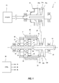
- Fig. 1 is an explanatory view illustrating the structure of a continuously variable transmission 1 according to a first embodiment of the present invention.
- the continuously variable transmission 1 is mounted on a vehicle, and drives the vehicle by changing the speed of rotation of an engine 10 as a driving source and outputting it.
- the continuously variable transmission 1 is formed by a primary pulley 21, a secondary pulley 22, and a V-belt 23.
- the rotation from the engine 10, as a driving power source, is inputted to a rotation shaft (primary shaft) 11 of the primary pulley 21.
- Rotation outputted from a rotation shaft (secondary shaft) 12 of the secondary pulley 22 rotates not-illustrated driving wheels and drives the vehicle.
- the V-belt 23 is extended between a V-groove 21c that is formed by a fixed conical plate 21a and a movable conical plate 21 b of the primary pulley 21, and a V-groove 22c that is formed by a fixed conical plate 22a and a movable conical plate 22b of the secondary pulley 22.
- the speed of rotation that is inputted from the primary shaft 11 is changed and outputted from the secondary shaft 12.
- the shift is performed in this manner.
- the upper side from the dashed line illustrates the case where a speed ratio (pulley ratio) is on a Lo side
- the lower side illustrates the case where the speed ratio is on a Hi side.
- the primary pulley 21 is provided with a hydraulic chamber 25.
- the movable conical plate 21b is advanced/retreated so as to change the groove width of the V-groove 21c.
- the secondary pulley 22 is formed by the fixed conical plate 22a that is coupled to the secondary shaft 12 and rotated integrally with the secondary shaft 12, and the movable conical plate 22b that is fitted to the secondary shaft 12 to be able to slide in the axial direction of the secondary shaft 12.
- the movable conical plate 22b is provided with a slide mechanism 50.
- the slide mechanism 50 changes the groove width of the V-groove 22c of the secondary pulley 22 when a controller 60 drives a motor generator 30 to advance/retreat the movable conical plate 22b, as will be described later.
- the slide mechanism 50 is formed by the motor generator 30, a planetary gear mechanism 40, a slide piston 52, several clutches and the like.
- the motor generator 30 is rotatably provided on the outer periphery of the secondary shaft 12 via a bearing 33.
- a stator 31 of the motor generator 30 is fixed to a case 2.
- a rotor 32 that is fitted inside the stator 31 is rotatably provided on the secondary shaft 12 via the bearing 33.
- the rotor 32 is connected to a sun gear 41 of the planetary gear mechanism 40 via a first clutch 34, and is formed in such a manner that rotation between the rotor 32 and the sun gear 41 is made discontinuous/continuous.
- the rotor 32 is also connected to the secondary shaft 12 via a second clutch 35, and is formed in such a manner that rotation between the rotor 32 and the secondary shaft 12 is made discontinuous/continuous.
- Each of the first clutch 34 and the second clutch 35 whose engaging power is controlled by an electromagnetic solenoid, for example, is controlled by the controller 60 to become an engaging state, a releasing state, and a slipping state with which rotation is transmitted with differential rotation between input rotation speed and output rotation speed.
- the engaging power of the first clutch 34 and the second clutch 35 may be controlled by hydraulic pressure.
- the planetary gear mechanism 40 is formed by the sun gear 41, pinions 42, and a ring gear 43.
- the inner periphery of the sun gear 41 is rotatably fitted on the secondary shaft 12 via a bearing 44.
- a carrier that connects the pinions 42 is fixed to the case 2, and the planetary gear mechanism 40 decelerates rotation of the sun gear 41 and transmits it to the ring gear 43.
- the slide piston 52 is provided on the outer periphery side of the ring gear 43.
- a ball screw 53 is interposed between the ring gear 43 and the slide piston 52 so that the slide piston 52 makes forward/backward movement in the axial direction of the secondary shaft 12 by rotation of the ring gear 43.
- the ball screw 53 causes the slide piston 52 to make the forward/backward movement by rotation of the planetary gear mechanism 40, but an angle of repose is set in such a manner that the planetary gear mechanism 40 does not rotate depending on the power of the slide piston 52 in the axial direction.
- the slide piston 52 does not move depending on thrust of the secondary pulley 22.
- the slide piston 52 is spline-fitted to the case 2, and is formed to make the forward/backward movement by the planetary gear mechanism 40, as described above.
- the slide piston 52 has a cylindrical shape that is coaxial with the secondary shaft 12, and, at the end part of its cylindrical shape, abuts against the end part side, in the radial direction, of the movable conical plate 22b of the secondary pulley 22, via a bearing 55.
- the controller 60 changes the groove width of the V-groove 22c of the secondary pulley 22, by controlling driving of the motor generator 30 and engagement and release of the first clutch 34 and the second clutch 35.
- the controller 60 controls the groove width of the V-groove 22c of the secondary pulley 22 in response to the groove width of the V-groove 21c of the primary pulley 21, so as to control the speed ratio of the continuously variable transmission 1.
- the continuously variable transmission 1 is a combination of the conventionally-known primary pulley 21 that changes the groove width by moving the movable conical plate 21b by the hydraulic pressure, and the secondary pulley 22 that changes the groove width by moving the movable conical plate 22b by driving the motor generator 30.
- the controller 60 decides a target value of the speed ratio based on the vehicle speed, an acceleration/deceleration request, engine rotation speed and the like, and decides indicated oil pressure to the primary pulley 21 so that an actual speed ratio of the continuously variable transmission 1 follows the target value. Based on the indicated oil pressure, the hydraulic pressure is supplied to the hydraulic chamber 25 of the primary pulley 21, the movable conical plate 21 b advances/ retreats, and the groove width is changed.
- the controller 60 causes the first clutch 34 and the second clutch 35 to be in the engaging state and in the releasing state, respectively, makes the motor generator 30 to perform power running, and causes the movable conical plate 22b of the secondary pulley 22 to advance/retreat.
- the groove width of the V-groove 22c of the secondary pulley 22 is changed in response to the movement of the primary pulley 21.
- the hydraulic mechanism is used only on the primary pulley 21 side, and thus the hydraulic pressure, required for shift, can be reduced, the friction of the hydraulic pump can be reduced, and the fuel efficiency can be improved.
- controller 60 drives the motor generator 30 by the rotation of the secondary shaft 12 of the secondary pulley 22, and regenerates rotational energy as power.
- the regenerated power is charged to a battery or the like. The details will be explained below.
- the controller 60 When the vehicle is decelerating and when the speed ratio of the continuously variable transmission 1 is not changed, the controller 60 causes the first clutch 34 to be in the releasing state and the second clutch 35 to be in the engaging state. Thereby, the rotor 32 of the motor generator 30 rotates together with the secondary shaft 12. The controller 60 causes the motor generator 30 to function as a generator, so as to regenerate the rotational energy of the secondary shaft 12 as power. The regenerated power is charged to the battery or the like by the controller 60.
- the controller 60 causes the motor generator 30 to function as a motor. Thereby, the rotor 32 of the motor generator 30 rotates, and the rotation is transmitted via the second clutch 35 to the secondary shaft 12.
- an assist can be provided to driving power of the driving power source that applies rotation to the secondary pulley 22.
- the power to drive the motor generator 30 is obtained by the regeneration, the energy efficiency of the driving power source can be improved.
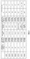
- Fig. 2 is an explanatory view illustrating the state of the secondary pulley 22 according to this embodiment.
- Fig. 2 illustrates the state of an accelerator pedal, the rotation direction of the primary shaft 11, the direction of the shift, the operation state of the motor generator 30, the rotation direction of the motor generator 30, and the states of the first clutch 34 and the second clutch 35, respectively.
- the controller 60 When a driver depresses the accelerator pedal (accelerator is ON) and when the speed ratio is shifted from the Lo side to the Hi side, the controller 60 causes the first clutch 34 to be in the engaging state (ON), and the second clutch 35 to be in the releasing state (OFF), and makes shift operation of the motor generator 30 in the direction of reverse rotation. Thereby, the groove width of the secondary pulley 22 is changed in response to the operation of the primary pulley 21, and the speed ratio is shifted from the Lo side to the Hi side (mode 1).
- the controller 60 causes the first clutch 34 to be ON and the second clutch 35 to be OFF, and makes the shift operation of the motor generator 30 in the direction of forward rotation.
- the groove width of the secondary pulley 22 is changed in response to the operation of the primary pulley 21, and the speed ratio is shifted from the Hi side to the Lo side (mode 2).
- the controller 60 When the driver does not depress the accelerator pedal (accelerator is OFF) and when the speed ratio is shifted from the Lo side to the Hi side, the controller 60 causes the first clutch 34 to be ON and the second clutch 35 to be OFF, and makes the shift operation of the motor generator 30 in the direction of the reverse rotation. Thereby, the groove width of the secondary pulley 22 is changed in response to the operation of the primary pulley 21, and the speed ratio is shifted from the Lo side to the Hi side (mode 3).
- the controller 60 causes the first clutch 34 to be ON and the second clutch 35 to be OFF, and makes the shift operation of the motor generator 30 in the direction of the forward rotation.
- the groove width of the secondary pulley 22 is changed in response to the operation of the primary pulley 21, and the speed ratio is shifted from the Hi side to the Lo side (mode 4).
- the controller 60 causes the first clutch 34 to be OFF and the second clutch 35 to be ON, causes the motor generator 30 to function as the generator, and makes regeneration operation in the direction of the forward rotation. Thereby, power is generated as the rotation of the secondary shaft 12 is transmitted to the motor generator 30, and the rotational energy is regenerated as power (mode 5).
- the controller 60 controls the first clutch 34 to become OFF from ON, and the second clutch 35 to become ON from OFF, respectively, and starts the regeneration by the motor generator 30. This operation will be described in detail with reference to Fig. 3 (mode 6).
- the controller 60 causes the first clutch 34 to be OFF and the second clutch 35 to be ON, and drives the motor generator 30 in the direction of the forward rotation. Thereby, the rotation of the motor generator 30 is transmitted to the secondary shaft 12, and an assist can be provided to the driving power of the vehicle (mode 7).
- controller 60 controls the first clutch 34, the second clutch 35, and the motor generator 30 based on the state of the accelerator pedal, as described above, it is possible to control the speed ratio and to regenerate the rotational energy as power.
- the controller 60 changes the speed ratio to the Lo side and starts the regeneration by the motor generator 30 by the following operation.
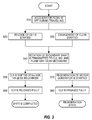
- Fig. 3 is a flowchart of the control of the mode 6 according to this embodiment.
- the controller 60 starts the flowchart of Fig. 3 when it is determined that the accelerator is OFF.
- the controller 60 starts the release of the first clutch 34 and at the same time, starts the engagement of the second clutch 35.
- the engaging state of the first clutch 34 and the second clutch 35 is respectively controlled by the solenoids.
- the controller 60 controls a current to be applied to the solenoids, and starts the engagement of the first clutch 34 and the release of the second clutch 35 (steps S20, S30).
- both of the first clutch 34 and the second clutch 35 become the slipping state (half-clutch state), and the rotation is transmitted with a speed difference between the input rotation speed and the output rotation speed.
- the rotation of the secondary shaft 12 is transmitted via the second clutch 35 to the rotor 32 of the motor generator 30.
- the rotation of the rotor 32 is also transmitted via the first clutch 34 in the slipping state to the sun gear 41 of the planetary gear mechanism 40 (S40).
- the rotation transmitted to the sun gear 41 acts in such a manner that the planetary gear mechanism 40 retreats the slide piston 52.
- the movable conical plate 22b of the secondary pulley 22 can be moved.
- the groove width of the V-groove 22c of the secondary pulley 22 increases.
- the rotor 32 of the motor generator 30 rotates via the second clutch 35.
- the controller 60 causes the motor generator 30 to function as the generator, and starts the regeneration of this rotational energy (S70).
- the motor generator 30 rotates by the rotation of the secondary shaft 12 (S80).
- the motor generator 30 regenerates this rotational energy as power.
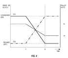
- Fig. 4 is a time chart illustrating the control of the mode 6 according to this embodiment.
- the solid line illustrates the engaging state of the first clutch 34
- the alternate long and short dashed line illustrates the engaging state of the second clutch 35
- the dotted line illustrates the speed ratio (pulley ratio), respectively.
- the first clutch 34 is in the engaging state and the second clutch 35 is in the releasing state.
- the speed ratio at this time is the predetermined speed ratio on the Hi side.
- the rotation of the secondary shaft 12 rotates the motor generator 30 and the planetary gear mechanism 40 and moves the slide piston 52.
- the groove widths of the primary pulley 21 and the secondary pulley 22 respond to each other appropriately, and the speed ratio is gradually shifted to the Lo side.
- the speed ratio can be shifted from Hi to Lo by using kinetic energy of the vehicle only, without causing the motor generator 30 to consume power for driving.
- the regeneration by the motor generator 30 can also be made during the shift, and thus the energy efficiency can be improved.
- the first embodiment according to the present invention is formed as the continuously variable transmission 1 that is provided with the primary pulley 21, the secondary pulley 22, and the V-belt 23, and that performs shift by changing the groove widths of the primary pulley 21 and the secondary pulley 22.
- the secondary pulley 22 is provided with the fixed conical plate 22a that is fixed to the secondary shaft 12, the movable conical plate 22b that moves in the axial direction of the secondary shaft 12 with respect to the fixed conical plate 22a, and the slide mechanism 50 that moves the movable conical plate 22b.
- the slide mechanism 50 is provided with the slide piston 52 that causes the movable conical plate 22b to advance/retreat, the motor generator 30 that moves the slide piston 52, the planetary gear mechanism 40 that is interposed between the motor generator 30 and the slide piston 52, the first clutch 34 that makes the rotation between the motor generator 30 and the planetary gear mechanism 40 discontinuous/continuous, the second clutch 35 that makes the rotation between the secondary shaft 12 and the motor generator 30 discontinuous/continuous, and the controller 60 that controls the operation of the motor generator 30.
- the movable conical plate 22b can be moved and the groove width of the secondary pulley 22 can be changed, by rotating the motor generator 30 and moving the slide piston in the axial direction of the secondary shaft 12.
- the primary pulley 21 is subjected to the hydraulic control, and the size and the capacity of the hydraulic pump that generates the hydraulic pressure can be reduced, as a result of which the friction is reduced and the fuel efficiency of the driving source can be improved.
- the secondary pulley 22 does not use the hydraulic pressure for changing the groove width, it does not have a hydraulic chamber, and it is not necessary for the secondary pulley 22 to be provided with a centrifugal hydraulic chamber in order to avoid an influence of centrifugal hydraulic pressure of the hydraulic chamber.
- the hydraulic pressure and oil quantity used for changing the speed can be reduced like this, the size and the capacity of the hydraulic pump can be reduced, the friction can be reduced, and the fuel efficiency of the driving source can be improved.
- the motor generator 30 is rotated by the rotation of the secondary shaft 12, and the rotational energy can be regenerated as power.
- the regenerated power is used for driving the motor generator 30.
- the slide piston 52 is structured in such a manner that it abuts against the movable conical plate 22b on the side of the outer periphery in the radial direction of the movable conical plate 22b, so as to move the movable conical plate 22b in the axial direction.
- the structure like this it is possible to prevent the power (thrust) applied to the V-belt 23 and a sheave surface of the movable conical plate 22b from making elastic deformation of the movable conical plate 22b in the direction expanding in the axial direction, and to minimize the energy for moving the slide piston 52.
- the controller 60 causes the first clutch 34 and the second clutch 35 to be in the slipping state during when the vehicle is decelerating, the rotation of the secondary shaft 12 causes the rotor 32 of the motor generator 30 that is being driven to rotate, and the rotation causes the slide piston 52 to move in the axial direction via the planetary gear mechanism 40.
- the movable conical plate 22b can be moved and the speed ratio can be changed by only the energy of the vehicle during deceleration, without driving the motor generator 30, and thus the fuel efficiency of the driving source can be improved.
- the second embodiment is a modified example of the first embodiment, and is provided with a second planetary gear mechanism 80 in order to improve regeneration efficiency at this time when the motor generator 30 is caused to function as the generator.
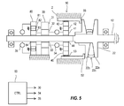
- Fig. 5 is an explanatory view of the secondary pulley 22 according to the second embodiment of the present invention.
- the motor generator 30 is rotatably provided on the outer periphery of the secondary shaft 12 via the bearing 33.
- the stator 31 of the motor generator 30 is fixed to the case 2.
- the rotor 32 of the motor generator 30 is connected to the sun gear 41 of the planetary gear mechanism 40 via the first clutch 34, and the rotation between the rotor 32 and the sun gear 41 can be made discontinuous/continuous.
- the rotor 32 is coupled to a sun gear 81 of the second planetary gear mechanism 80, and rotates together with the sun gear 81.
- the second planetary gear mechanism 80 is formed by the sun gear 81, double pinions 82, and a ring gear 83.
- the inner periphery of the sun gear 81 is provided to be able to rotate on the secondary shaft via a bearing 85.
- a carrier that connects the double pinions 82 is fixed to the case 2.
- the ring gear 83 is connected to the secondary shaft 12 via the second clutch 35, and the rotation between the ring gear 83 and the secondary shaft 12 can be made discontinuous / continuous.
- the first clutch 34 and the second clutch 35 are caused to become OFF and ON, respectively, and the rotation of the secondary shaft 12 is transmitted via the second planetary gear mechanism 80 to the motor generator 30.
- the rotation inputted to the sun gear 81 is transmitted via the double pinions 82 to the sun gear 81, and to the rotor 32 of the motor generator 30.
- the rotation of the secondary shaft 12 is transmitted via the second planetary gear mechanism 80, having the double pinions 82, to the motor generator 30, so that the rotation speed of the motor generator 30 can be increased. This makes it possible to improve the regeneration efficiency by the motor generator 30.
- the rotation of the motor generator 30 is decelerated by the second planetary gear mechanism 80 having the double pinions 82, and transmitted to the secondary shaft 12, resulting in a reduction in a torque to drive the motor generator 30 and a reduction in power consumption.
- the slide mechanism 50 may be provided on the primary pulley 21, and the secondary pulley 22 may be driven by the hydraulic pressure. More specifically, the controller 60 decides the target value of the speed ratio based on the vehicle speed, the acceleration/deceleration request, the engine rotation speed and the like, and controls the groove width of the primary pulley 21 in such a manner that the desired pulley ratio can be obtained from the vehicle speed, the input torque to the continuously variable transmission 1, the rotation speed of the primary pulley 21 and the secondary pulley 22 and the like. The groove width of the secondary pulley 22 is controlled in response to the groove width of the primary pulley 21.
- the slide mechanism 50 may be provided on each of the primary pulley 21 and the secondary pulley 22, and the groove widths may be changed by the operation of the motor generator 30.
- the size and the capacity of the hydraulic pump that generates the hydraulic pressure can be reduced, as a result of which the friction can be reduced, and the fuel efficiency of the driving source can be improved.
- the vehicle is provided with the engine 10 only as its power source, but it may be provided with the engine 10 and a motor for driving as the power sources, or it may be provided with the motor for driving only.
- the V-belt 23 may be formed by a plurality of pieces that are coupled by an endless metal belt, or by a rubber belt or a chain.
- the vehicle is provided with the continuously variable transmission 1 only, but it may be provided with a stepped transmission in series with the continuously variable transmission 1, so as to increase the range of the speed ratio.
- the hydraulic control of the second pulley, whose groove width is changed by the motor generator can be omitted, and the size and the capacity of the hydraulic pump that generates the hydraulic pressure can be reduced, as a result of which the friction can be reduced.
- the motor generator may be driven as the generator by the rotation of the rotation shaft, and the rotational energy can be regenerated as power.
Landscapes
- Engineering & Computer Science (AREA)
- General Engineering & Computer Science (AREA)
- Mechanical Engineering (AREA)
- Hybrid Electric Vehicles (AREA)
- Control Of Transmission Device (AREA)
- Chemical & Material Sciences (AREA)
- Combustion & Propulsion (AREA)
- Control Of Driving Devices And Active Controlling Of Vehicle (AREA)
- Electric Propulsion And Braking For Vehicles (AREA)
- Transmission Devices (AREA)
Abstract
Description
- The present invention relates to a continuously variable transmission that electrically drives a movable pulley, and a control method of the same.
- A conventional belt continuously variable transmission includes an endless belt or chain extending between V-grooves of a first pulley and a second pulley, and performs shift by changing widths of the V-grooves. These pulleys are driven by hydraulic pressure generated by a hydraulic pump, in order to maintain thrust for transmitting a rotation torque while sandwiching the belt.
- Meanwhile, friction of the hydraulic pump becomes a load for a driving power source, resulting in deterioration of fuel efficiency of the driving power source.
- In response to this,
JP2001-349401A - According to the conventional art as described in
JP2001-349401A - The technology as described in
JP2001-349401A - The present invention is made in view of the above-described problems, and its object is to provide a continuously variable transmission that electrically drives the movable conical plate and that can improve the fuel efficiency.
- According to an aspect of the present invention, a continuously variable transmission is provided which comprises a first pulley and a second pulley capable of changing groove widths; and a belt, extended between the first pulley and the second pulley, for transmitting rotation, wherein shift is performed by changing the groove widths of the first pulley and the second pulley. The second pulley comprises a fixed conical plate fixed to a rotation shaft, a movable conical plate moving in an axial direction of the rotation shaft with respect to the fixed conical plate, a slide mechanism moving the movable conical plate, and a controller controlling a state of the slide mechanism. The slide mechanism comprises a piston causing the movable conical plate to advance/retreat, a motor generator moving the piston in the axial direction, a planetary gear mechanism interposed between the motor generator and the piston, a first clutch making rotation between the motor generator and the planetary gear mechanism discontinuous/continuous, and a second clutch making rotation between the rotation shaft and the motor generator discontinuous/continuous. The controller changes the groove width of the second pulley by driving the motor generator, while the first clutch is engaged, and thus moving the movable conical plate, and drives the motor generator as a generator by the rotation of the rotation shaft, by engaging the second clutch.
-
-
Fig. 1 is an explanatory view illustrating the structure of a continuouslyvariable transmission 1 according to a first embodiment of the present invention; -
Fig. 2 is an explanatory view illustrating the state of a secondary pulley according to the first embodiment of the present invention; -
Fig. 3 is a flowchart of control of a mode 6 according to the first embodiment of the present invention; -
Fig. 4 is a time chart illustrating the control of the mode 6 according to the first embodiment of the present invention; and -
Fig. 5 is an explanatory view of a secondary pulley according to a second embodiment of the present invention. - Hereinafter, embodiments of the present invention will be explained with reference to the drawings.
-
Fig. 1 is an explanatory view illustrating the structure of a continuouslyvariable transmission 1 according to a first embodiment of the present invention. - The continuously
variable transmission 1 according to this embodiment is mounted on a vehicle, and drives the vehicle by changing the speed of rotation of anengine 10 as a driving source and outputting it. - The continuously
variable transmission 1 is formed by aprimary pulley 21, asecondary pulley 22, and a V-belt 23. The rotation from theengine 10, as a driving power source, is inputted to a rotation shaft (primary shaft) 11 of theprimary pulley 21. Rotation outputted from a rotation shaft (secondary shaft) 12 of thesecondary pulley 22 rotates not-illustrated driving wheels and drives the vehicle. - The V-
belt 23 is extended between a V-groove 21c that is formed by a fixedconical plate 21a and a movableconical plate 21 b of theprimary pulley 21, and a V-groove 22c that is formed by a fixedconical plate 22a and a movableconical plate 22b of thesecondary pulley 22. - By changing groove widths of the V-
grooves secondary shaft 12. The shift is performed in this manner. InFig. 1 , the upper side from the dashed line illustrates the case where a speed ratio (pulley ratio) is on a Lo side, and the lower side illustrates the case where the speed ratio is on a Hi side. - The
primary pulley 21 is provided with ahydraulic chamber 25. By changing hydraulic pressure to be supplied to the hydraulic chamber, the movableconical plate 21b is advanced/retreated so as to change the groove width of the V-groove 21c. - The
secondary pulley 22 is formed by the fixedconical plate 22a that is coupled to thesecondary shaft 12 and rotated integrally with thesecondary shaft 12, and the movableconical plate 22b that is fitted to thesecondary shaft 12 to be able to slide in the axial direction of thesecondary shaft 12. The movableconical plate 22b is provided with aslide mechanism 50. Theslide mechanism 50 changes the groove width of the V-groove 22c of thesecondary pulley 22 when acontroller 60 drives amotor generator 30 to advance/retreat the movableconical plate 22b, as will be described later. - The
slide mechanism 50 is formed by themotor generator 30, aplanetary gear mechanism 40, aslide piston 52, several clutches and the like. - The
motor generator 30 is rotatably provided on the outer periphery of thesecondary shaft 12 via abearing 33. Astator 31 of themotor generator 30 is fixed to acase 2. Arotor 32 that is fitted inside thestator 31 is rotatably provided on thesecondary shaft 12 via thebearing 33. Therotor 32 is connected to asun gear 41 of theplanetary gear mechanism 40 via afirst clutch 34, and is formed in such a manner that rotation between therotor 32 and thesun gear 41 is made discontinuous/continuous. Therotor 32 is also connected to thesecondary shaft 12 via asecond clutch 35, and is formed in such a manner that rotation between therotor 32 and thesecondary shaft 12 is made discontinuous/continuous. - Each of the
first clutch 34 and thesecond clutch 35, whose engaging power is controlled by an electromagnetic solenoid, for example, is controlled by thecontroller 60 to become an engaging state, a releasing state, and a slipping state with which rotation is transmitted with differential rotation between input rotation speed and output rotation speed. The engaging power of thefirst clutch 34 and thesecond clutch 35 may be controlled by hydraulic pressure. - The
planetary gear mechanism 40 is formed by thesun gear 41,pinions 42, and aring gear 43. The inner periphery of thesun gear 41 is rotatably fitted on thesecondary shaft 12 via abearing 44. A carrier that connects thepinions 42 is fixed to thecase 2, and theplanetary gear mechanism 40 decelerates rotation of thesun gear 41 and transmits it to thering gear 43. Theslide piston 52 is provided on the outer periphery side of thering gear 43. - A
ball screw 53 is interposed between thering gear 43 and theslide piston 52 so that theslide piston 52 makes forward/backward movement in the axial direction of thesecondary shaft 12 by rotation of thering gear 43. Theball screw 53 causes theslide piston 52 to make the forward/backward movement by rotation of theplanetary gear mechanism 40, but an angle of repose is set in such a manner that theplanetary gear mechanism 40 does not rotate depending on the power of theslide piston 52 in the axial direction. Thus, theslide piston 52 does not move depending on thrust of thesecondary pulley 22. - The
slide piston 52 is spline-fitted to thecase 2, and is formed to make the forward/backward movement by theplanetary gear mechanism 40, as described above. Theslide piston 52 has a cylindrical shape that is coaxial with thesecondary shaft 12, and, at the end part of its cylindrical shape, abuts against the end part side, in the radial direction, of the movableconical plate 22b of thesecondary pulley 22, via abearing 55. - The
controller 60 changes the groove width of the V-groove 22c of thesecondary pulley 22, by controlling driving of themotor generator 30 and engagement and release of thefirst clutch 34 and thesecond clutch 35. Thecontroller 60 controls the groove width of the V-groove 22c of thesecondary pulley 22 in response to the groove width of the V-groove 21c of theprimary pulley 21, so as to control the speed ratio of the continuouslyvariable transmission 1. - The operation of thus-structured continuously
variable transmission 1 according to the first embodiment will be explained. - The continuously
variable transmission 1 according to this embodiment is a combination of the conventionally-knownprimary pulley 21 that changes the groove width by moving the movableconical plate 21b by the hydraulic pressure, and thesecondary pulley 22 that changes the groove width by moving the movableconical plate 22b by driving themotor generator 30. - The
controller 60 decides a target value of the speed ratio based on the vehicle speed, an acceleration/deceleration request, engine rotation speed and the like, and decides indicated oil pressure to theprimary pulley 21 so that an actual speed ratio of the continuouslyvariable transmission 1 follows the target value. Based on the indicated oil pressure, the hydraulic pressure is supplied to thehydraulic chamber 25 of theprimary pulley 21, the movableconical plate 21 b advances/ retreats, and the groove width is changed. - According to the change in the groove width of the
primary pulley 21, thecontroller 60 causes thefirst clutch 34 and thesecond clutch 35 to be in the engaging state and in the releasing state, respectively, makes themotor generator 30 to perform power running, and causes the movableconical plate 22b of thesecondary pulley 22 to advance/retreat. Thus, the groove width of the V-groove 22c of thesecondary pulley 22 is changed in response to the movement of theprimary pulley 21. - With the structure like this according to this embodiment, the hydraulic mechanism is used only on the
primary pulley 21 side, and thus the hydraulic pressure, required for shift, can be reduced, the friction of the hydraulic pump can be reduced, and the fuel efficiency can be improved. - Further, the
controller 60 drives themotor generator 30 by the rotation of thesecondary shaft 12 of thesecondary pulley 22, and regenerates rotational energy as power. The regenerated power is charged to a battery or the like. The details will be explained below. - When the vehicle is decelerating and when the speed ratio of the continuously
variable transmission 1 is not changed, thecontroller 60 causes the first clutch 34 to be in the releasing state and the second clutch 35 to be in the engaging state. Thereby, therotor 32 of themotor generator 30 rotates together with thesecondary shaft 12. Thecontroller 60 causes themotor generator 30 to function as a generator, so as to regenerate the rotational energy of thesecondary shaft 12 as power. The regenerated power is charged to the battery or the like by thecontroller 60. - When the vehicle is required to accelerate at this time, the
controller 60 causes themotor generator 30 to function as a motor. Thereby, therotor 32 of themotor generator 30 rotates, and the rotation is transmitted via the second clutch 35 to thesecondary shaft 12. Thus, an assist can be provided to driving power of the driving power source that applies rotation to thesecondary pulley 22. As the power to drive themotor generator 30 is obtained by the regeneration, the energy efficiency of the driving power source can be improved. -
Fig. 2 is an explanatory view illustrating the state of thesecondary pulley 22 according to this embodiment. -
Fig. 2 illustrates the state of an accelerator pedal, the rotation direction of the primary shaft 11, the direction of the shift, the operation state of themotor generator 30, the rotation direction of themotor generator 30, and the states of the first clutch 34 and the second clutch 35, respectively. - When a driver depresses the accelerator pedal (accelerator is ON) and when the speed ratio is shifted from the Lo side to the Hi side, the
controller 60 causes the first clutch 34 to be in the engaging state (ON), and the second clutch 35 to be in the releasing state (OFF), and makes shift operation of themotor generator 30 in the direction of reverse rotation. Thereby, the groove width of thesecondary pulley 22 is changed in response to the operation of theprimary pulley 21, and the speed ratio is shifted from the Lo side to the Hi side (mode 1). - Similarly, when the accelerator is ON and when the speed ratio is shifted from the Hi side to the Lo side, the
controller 60 causes the first clutch 34 to be ON and the second clutch 35 to be OFF, and makes the shift operation of themotor generator 30 in the direction of forward rotation. Thereby, the groove width of thesecondary pulley 22 is changed in response to the operation of theprimary pulley 21, and the speed ratio is shifted from the Hi side to the Lo side (mode 2). - When the driver does not depress the accelerator pedal (accelerator is OFF) and when the speed ratio is shifted from the Lo side to the Hi side, the
controller 60 causes the first clutch 34 to be ON and the second clutch 35 to be OFF, and makes the shift operation of themotor generator 30 in the direction of the reverse rotation. Thereby, the groove width of thesecondary pulley 22 is changed in response to the operation of theprimary pulley 21, and the speed ratio is shifted from the Lo side to the Hi side (mode 3). - Similarly, when the accelerator is OFF and when the speed ratio is shifted from the Hi side to the Lo side, the
controller 60 causes the first clutch 34 to be ON and the second clutch 35 to be OFF, and makes the shift operation of themotor generator 30 in the direction of the forward rotation. Thereby, the groove width of thesecondary pulley 22 is changed in response to the operation of theprimary pulley 21, and the speed ratio is shifted from the Hi side to the Lo side (mode 4). - When the accelerator is OFF and when the speed ratio is not changed (when the speed ratio is fixed), the
controller 60 causes the first clutch 34 to be OFF and the second clutch 35 to be ON, causes themotor generator 30 to function as the generator, and makes regeneration operation in the direction of the forward rotation. Thereby, power is generated as the rotation of thesecondary shaft 12 is transmitted to themotor generator 30, and the rotational energy is regenerated as power (mode 5). - When the accelerator is OFF and when the mode is changed from the mode 3 or the mode 4 to the mode 5, by which the regeneration operation of the
motor generator 30 is made, thecontroller 60 controls the first clutch 34 to become OFF from ON, and the second clutch 35 to become ON from OFF, respectively, and starts the regeneration by themotor generator 30. This operation will be described in detail with reference toFig. 3 (mode 6). - Further, when the driver depresses the accelerator and when the speed ratio is not changed, the
controller 60 causes the first clutch 34 to be OFF and the second clutch 35 to be ON, and drives themotor generator 30 in the direction of the forward rotation. Thereby, the rotation of themotor generator 30 is transmitted to thesecondary shaft 12, and an assist can be provided to the driving power of the vehicle (mode 7). - As the
controller 60 controls the first clutch 34, the second clutch 35, and themotor generator 30 based on the state of the accelerator pedal, as described above, it is possible to control the speed ratio and to regenerate the rotational energy as power. - Next, the control of the above-described mode 6 in
Fig. 2 will be explained. - When the driver releases the depression of the accelerator pedal and the accelerator becomes OFF, during when the vehicle is travelling, the
controller 60 changes the speed ratio to the Lo side and starts the regeneration by themotor generator 30 by the following operation. -
Fig. 3 is a flowchart of the control of the mode 6 according to this embodiment. - The
controller 60 starts the flowchart ofFig. 3 when it is determined that the accelerator is OFF. - First, the
controller 60 starts the release of the first clutch 34 and at the same time, starts the engagement of thesecond clutch 35. The engaging state of the first clutch 34 and the second clutch 35 is respectively controlled by the solenoids. Thecontroller 60 controls a current to be applied to the solenoids, and starts the engagement of the first clutch 34 and the release of the second clutch 35 (steps S20, S30). Thereby, both of the first clutch 34 and the second clutch 35 become the slipping state (half-clutch state), and the rotation is transmitted with a speed difference between the input rotation speed and the output rotation speed. - As the second clutch 35 becomes the slipping state, the rotation of the
secondary shaft 12 is transmitted via the second clutch 35 to therotor 32 of themotor generator 30. In addition, the rotation of therotor 32 is also transmitted via the first clutch 34 in the slipping state to thesun gear 41 of the planetary gear mechanism 40 (S40). - The rotation transmitted to the
sun gear 41 acts in such a manner that theplanetary gear mechanism 40 retreats theslide piston 52. Thus, the movableconical plate 22b of thesecondary pulley 22 can be moved. When theslide piston 52 retreats, the groove width of the V-groove 22c of thesecondary pulley 22 increases. By appropriately controlling the groove width of theprimary pulley 21, in response to the operation of thesecondary pulley 22, the speed ratio of the continuouslyvariable transmission 1 can be shifted to the Lo side, without driving the motor generator 30 (S50). As the speed ratio is shifted to the Lo side during deceleration like this, it is possible to prepare for the subsequent acceleration request to be made by the driver. - Further, the
rotor 32 of themotor generator 30 rotates via thesecond clutch 35. Thecontroller 60 causes themotor generator 30 to function as the generator, and starts the regeneration of this rotational energy (S70). - Thereafter, when the first clutch 34 becomes the releasing state fully, the operation of the
slide piston 52 stops, and the groove width of the V-groove 22c of thesecondary pulley 22 is set at the predetermined groove width (S60). - Further, when the second clutch 35 becomes the engaging state fully, the
motor generator 30 rotates by the rotation of the secondary shaft 12 (S80). Themotor generator 30 regenerates this rotational energy as power. -
Fig. 4 is a time chart illustrating the control of the mode 6 according to this embodiment. InFig. 4 , the solid line illustrates the engaging state of the first clutch 34, the alternate long and short dashed line illustrates the engaging state of the second clutch 35, and the dotted line illustrates the speed ratio (pulley ratio), respectively. - In the
mode 1 to the mode 4, the first clutch 34 is in the engaging state and the second clutch 35 is in the releasing state. The speed ratio at this time is the predetermined speed ratio on the Hi side. - When the accelerator becomes OFF and a decision on the shift to the mode 6 is made at timing t1, the release of the first clutch 34 is started and the engagement of the second clutch 35 is started. Thereby, both of the first clutch 34 and the second clutch 35 become the slipping state (steps S10 and S20 in
Fig. 3 ). - As engaging capacity of the second clutch 35 gradually increases, the rotation of the
secondary shaft 12 rotates themotor generator 30 and theplanetary gear mechanism 40 and moves theslide piston 52. By appropriately controlling the hydraulic pressure in theprimary pulley 21, the groove widths of theprimary pulley 21 and thesecondary pulley 22 respond to each other appropriately, and the speed ratio is gradually shifted to the Lo side. - When the first clutch 34 becomes the releasing state fully and the second clutch 35 becomes the engaging state fully, the
slide piston 52 is stopped and the speed ratio is fixed at the predetermined speed ratio Lo (timing t2). Under this state, the rotation from thesecondary shaft 12 is transmitted via the second clutch to themotor generator 30, and the rotational energy is regenerated as power. - Thus, by the operation of the mode 6, the speed ratio can be shifted from Hi to Lo by using kinetic energy of the vehicle only, without causing the
motor generator 30 to consume power for driving. The regeneration by themotor generator 30 can also be made during the shift, and thus the energy efficiency can be improved. - As has been explained thus far, the first embodiment according to the present invention is formed as the continuously
variable transmission 1 that is provided with theprimary pulley 21, thesecondary pulley 22, and the V-belt 23, and that performs shift by changing the groove widths of theprimary pulley 21 and thesecondary pulley 22. - The
secondary pulley 22 is provided with the fixedconical plate 22a that is fixed to thesecondary shaft 12, the movableconical plate 22b that moves in the axial direction of thesecondary shaft 12 with respect to the fixedconical plate 22a, and theslide mechanism 50 that moves the movableconical plate 22b. - The
slide mechanism 50 is provided with theslide piston 52 that causes the movableconical plate 22b to advance/retreat, themotor generator 30 that moves theslide piston 52, theplanetary gear mechanism 40 that is interposed between themotor generator 30 and theslide piston 52, the first clutch 34 that makes the rotation between themotor generator 30 and theplanetary gear mechanism 40 discontinuous/continuous, the second clutch 35 that makes the rotation between thesecondary shaft 12 and themotor generator 30 discontinuous/continuous, and thecontroller 60 that controls the operation of themotor generator 30. - According to this structure, the movable
conical plate 22b can be moved and the groove width of thesecondary pulley 22 can be changed, by rotating themotor generator 30 and moving the slide piston in the axial direction of thesecondary shaft 12. Thereby, only theprimary pulley 21 is subjected to the hydraulic control, and the size and the capacity of the hydraulic pump that generates the hydraulic pressure can be reduced, as a result of which the friction is reduced and the fuel efficiency of the driving source can be improved. - Further, as the
secondary pulley 22 does not use the hydraulic pressure for changing the groove width, it does not have a hydraulic chamber, and it is not necessary for thesecondary pulley 22 to be provided with a centrifugal hydraulic chamber in order to avoid an influence of centrifugal hydraulic pressure of the hydraulic chamber. As the hydraulic pressure and oil quantity used for changing the speed can be reduced like this, the size and the capacity of the hydraulic pump can be reduced, the friction can be reduced, and the fuel efficiency of the driving source can be improved. - Further, the
motor generator 30 is rotated by the rotation of thesecondary shaft 12, and the rotational energy can be regenerated as power. The regenerated power is used for driving themotor generator 30. By the structure like this, the fuel efficiency of the driving source can be improved. - Furthermore, the
slide piston 52 is structured in such a manner that it abuts against the movableconical plate 22b on the side of the outer periphery in the radial direction of the movableconical plate 22b, so as to move the movableconical plate 22b in the axial direction. By the structure like this, it is possible to prevent the power (thrust) applied to the V-belt 23 and a sheave surface of the movableconical plate 22b from making elastic deformation of the movableconical plate 22b in the direction expanding in the axial direction, and to minimize the energy for moving theslide piston 52. - Further, according to this embodiment, the
controller 60 causes the first clutch 34 and the second clutch 35 to be in the slipping state during when the vehicle is decelerating, the rotation of thesecondary shaft 12 causes therotor 32 of themotor generator 30 that is being driven to rotate, and the rotation causes theslide piston 52 to move in the axial direction via theplanetary gear mechanism 40. Thereby, the movableconical plate 22b can be moved and the speed ratio can be changed by only the energy of the vehicle during deceleration, without driving themotor generator 30, and thus the fuel efficiency of the driving source can be improved. - Next, the continuously
variable transmission 1 according to a second embodiment of the present invention will be explained. - The second embodiment is a modified example of the first embodiment, and is provided with a second
planetary gear mechanism 80 in order to improve regeneration efficiency at this time when themotor generator 30 is caused to function as the generator. -
Fig. 5 is an explanatory view of thesecondary pulley 22 according to the second embodiment of the present invention. - The
motor generator 30 is rotatably provided on the outer periphery of thesecondary shaft 12 via thebearing 33. Thestator 31 of themotor generator 30 is fixed to thecase 2. Therotor 32 of themotor generator 30 is connected to thesun gear 41 of theplanetary gear mechanism 40 via the first clutch 34, and the rotation between therotor 32 and thesun gear 41 can be made discontinuous/continuous. Therotor 32 is coupled to asun gear 81 of the secondplanetary gear mechanism 80, and rotates together with thesun gear 81. - The second
planetary gear mechanism 80 is formed by thesun gear 81,double pinions 82, and aring gear 83. The inner periphery of thesun gear 81 is provided to be able to rotate on the secondary shaft via a bearing 85. A carrier that connects thedouble pinions 82 is fixed to thecase 2. Thering gear 83 is connected to thesecondary shaft 12 via the second clutch 35, and the rotation between thering gear 83 and thesecondary shaft 12 can be made discontinuous / continuous. - The operation of thus-structured second embodiment is the same as that of the first embodiment.
- In the above-described mode 5, the first clutch 34 and the second clutch 35 are caused to become OFF and ON, respectively, and the rotation of the
secondary shaft 12 is transmitted via the secondplanetary gear mechanism 80 to themotor generator 30. - With the second
planetary gear mechanism 80, the rotation inputted to thesun gear 81 is transmitted via thedouble pinions 82 to thesun gear 81, and to therotor 32 of themotor generator 30. Thus, the rotation of thesecondary shaft 12 is transmitted via the secondplanetary gear mechanism 80, having thedouble pinions 82, to themotor generator 30, so that the rotation speed of themotor generator 30 can be increased. This makes it possible to improve the regeneration efficiency by themotor generator 30. - Further, in the mode 7, when the first clutch 34 and the second clutch 35 are caused to become OFF and ON, respectively, and the
motor generator 30 is driven to provide an assist to the rotation of thesecondary shaft 12, the rotation of themotor generator 30 is transmitted via the secondplanetary gear mechanism 80 to the secondary shaft. - In this case, the rotation of the
motor generator 30 is decelerated by the secondplanetary gear mechanism 80 having thedouble pinions 82, and transmitted to thesecondary shaft 12, resulting in a reduction in a torque to drive themotor generator 30 and a reduction in power consumption. - The embodiments of the present invention have been explained thus far. However, the above-described embodiments are only a part of application examples of the present invention, and are not intended to limit the technical scope of the present invention to the concrete structures of the above-described embodiments.
- According to the above-described embodiments, the structure of providing the
slide mechanism 50 in thesecondary pulley 22 has been explained. This is because the control can be simplified, as the groove width of thesecondary pulley 22 has only to be changed in response to the groove width of theprimary pulley 21, in a belt continuouslyvariable transmission 1. - Meanwhile, the
slide mechanism 50 may be provided on theprimary pulley 21, and thesecondary pulley 22 may be driven by the hydraulic pressure. More specifically, thecontroller 60 decides the target value of the speed ratio based on the vehicle speed, the acceleration/deceleration request, the engine rotation speed and the like, and controls the groove width of theprimary pulley 21 in such a manner that the desired pulley ratio can be obtained from the vehicle speed, the input torque to the continuouslyvariable transmission 1, the rotation speed of theprimary pulley 21 and thesecondary pulley 22 and the like. The groove width of thesecondary pulley 22 is controlled in response to the groove width of theprimary pulley 21. - Alternatively, the
slide mechanism 50 may be provided on each of theprimary pulley 21 and thesecondary pulley 22, and the groove widths may be changed by the operation of themotor generator 30. By the structure like this, the size and the capacity of the hydraulic pump that generates the hydraulic pressure can be reduced, as a result of which the friction can be reduced, and the fuel efficiency of the driving source can be improved. - According to the above-described embodiments, the vehicle is provided with the
engine 10 only as its power source, but it may be provided with theengine 10 and a motor for driving as the power sources, or it may be provided with the motor for driving only. - According to the above-described embodiments, the V-
belt 23 may be formed by a plurality of pieces that are coupled by an endless metal belt, or by a rubber belt or a chain. - According to the above-described embodiments, the vehicle is provided with the continuously
variable transmission 1 only, but it may be provided with a stepped transmission in series with the continuouslyvariable transmission 1, so as to increase the range of the speed ratio. - According to the embodiments of the present invention, the hydraulic control of the second pulley, whose groove width is changed by the motor generator, can be omitted, and the size and the capacity of the hydraulic pump that generates the hydraulic pressure can be reduced, as a result of which the friction can be reduced. Further, the motor generator may be driven as the generator by the rotation of the rotation shaft, and the rotational energy can be regenerated as power. By the structure like this, it is possible to improve the fuel efficiency of the driving source.
- The present application claims a priority of Japanese Patent Application No.
2013-220318 filed with the Japan Patent Office on October 23, 2013
Claims (7)
- A continuously variable transmission comprising:a first pulley and a second pulley capable of changing groove widths; anda belt, extended between the first pulley and the second pulley, for transmitting rotation,wherein shift is performed by changing the groove widths of the first pulley and the second pulley,wherein the second pulley comprisesa fixed conical plate fixed to a rotation shaft,a movable conical plate moving in an axial direction of the rotation shaft with respect to the fixed conical plate,a slide mechanism moving the movable conical plate, anda controller controlling a state of the slide mechanism,wherein the slide mechanism comprisesa piston causing the movable conical plate to advance/retreat,a motor generator moving the piston in the axial direction,a planetary gear mechanism interposed between the motor generator and the piston,a first clutch making rotation between the motor generator and the planetary gear mechanism discontinuous/continuous, anda second clutch making rotation between the rotation shaft and the motor generator discontinuous/continuous,and wherein the controller changes the groove width of the second pulley by driving the motor generator, while the first clutch is engaged, and thus moving the movable conical plate, and drives the motor generator as a generator by the rotation of the rotation shaft, by engaging the second clutch.
- The continuously variable transmission according to claim 1, wherein the piston abuts against the movable conical plate on an outer periphery side in a radial direction of the movable conical plate.
- The continuously variable transmission according to claim 1 or claim 2,
wherein the controller causes the first clutch and the second clutch to be in a slipping state, rotates the motor generator and the planetary gear mechanism by the rotation of the rotation shaft, and moves the piston in the axial direction. - The continuously variable transmission according to any one of claim 1 to claim 3,
wherein a second planetary gear mechanism is provided between the motor generator and the rotation shaft, and
wherein, when the second clutch is engaged, the rotation of the rotation shaft is accelerated by the second planetary gear mechanism, and transmitted to the motor generator. - The continuously variable transmission according to any one of claim 1 to claim 4,
wherein the first pulley is provided on a side of a driving power source, and the rotation shaft of the second pulley outputs the rotation after the shift. - The continuously variable transmission according to any one of claim 1 to claim 4,
wherein the second pulley is provided on a side of a driving power source, and the rotation shaft of the first pulley outputs the rotation after the shift. - A control method of a continuously variable transmission, including a first pulley and a second pulley capable of changing groove widths, and a belt, extended between the first pulley and the second pulley, for transmitting rotation, the second pulley including a fixed conical plate fixed to a rotation shaft, a movable conical plate moving in an axial direction of the rotation shaft with respect to the fixed conical plate, and a slide mechanism moving the movable conical plate, and the slide mechanism including a piston causing the movable conical plate to advance/retreat, a motor generator moving the piston in the axial direction, a planetary gear mechanism interposed between the motor generator and the piston, a first clutch making rotation between the motor generator and the planetary gear mechanism discontinuous/continuous, and a second clutch making rotation between the rotation shaft and the motor generator discontinuous/continuous, the control method of the continuously variable transmission comprising:changing the groove width of the second pulley by driving the motor generator, while the first clutch is engaged, and thus moving the movable conical plate; anddriving the motor generator as a generator by the rotation of the rotation shaft, by engaging the second clutch.
Applications Claiming Priority (2)
| Application Number | Priority Date | Filing Date | Title |
|---|---|---|---|
| JP2013220318A JP5945527B2 (en) | 2013-10-23 | 2013-10-23 | Continuously variable transmission and control method of continuously variable transmission |
| PCT/JP2014/077729 WO2015060219A1 (en) | 2013-10-23 | 2014-10-17 | Stepless transmission and method for controlling stepless transmission |
Publications (3)
| Publication Number | Publication Date |
|---|---|
| EP3061993A1 true EP3061993A1 (en) | 2016-08-31 |
| EP3061993A4 EP3061993A4 (en) | 2017-01-04 |
| EP3061993B1 EP3061993B1 (en) | 2017-12-13 |
Family
ID=52992816
Family Applications (1)
| Application Number | Title | Priority Date | Filing Date |
|---|---|---|---|
| EP14855170.8A Not-in-force EP3061993B1 (en) | 2013-10-23 | 2014-10-17 | Continuously variable transmission and control method of continuously variable transmission |
Country Status (6)
| Country | Link |
|---|---|
| US (1) | US9689476B2 (en) |
| EP (1) | EP3061993B1 (en) |
| JP (1) | JP5945527B2 (en) |
| KR (1) | KR101764077B1 (en) |
| CN (1) | CN105518349B (en) |
| WO (1) | WO2015060219A1 (en) |
Families Citing this family (5)
| Publication number | Priority date | Publication date | Assignee | Title |
|---|---|---|---|---|
| JP6859631B2 (en) * | 2016-08-29 | 2021-04-14 | 日産自動車株式会社 | Control method and control device for continuously variable transmission |
| CN109642647B (en) * | 2016-10-11 | 2021-07-20 | 加特可株式会社 | Pulley propulsion device for automatic transmission and control device for automatic transmission |
| JP6874656B2 (en) * | 2017-11-27 | 2021-05-19 | 日産自動車株式会社 | Control method and control device for automatic transmission |
| WO2019229490A1 (en) * | 2018-05-30 | 2019-12-05 | Carrier Corporation | Energy management systems (ems) for transportation refrigeration units (tru) |
| CN108895130A (en) * | 2018-08-08 | 2018-11-27 | 李兆勇 | A chain type continuously variable transmission mechanism |
Family Cites Families (14)
| Publication number | Priority date | Publication date | Assignee | Title |
|---|---|---|---|---|
| IT1032839B (en) * | 1975-05-09 | 1979-06-20 | Sira Societa Ind Richerche Aut | CONTINUOUS SPEED VARIATOR FOR MOTORPOWER GROUPS |
| NL1011732C2 (en) * | 1999-04-06 | 2000-10-09 | Skf Engineering & Res Services | Pulley kit for a continuously variable transmission unit. |
| JP2001349401A (en) | 2000-06-02 | 2001-12-21 | Yamaha Motor Co Ltd | Control mechanism for continuously variable transmission |
| JP2001355697A (en) * | 2000-06-12 | 2001-12-26 | Yamaha Motor Co Ltd | Continuously variable transmission |
| EP1579126B1 (en) | 2002-12-23 | 2006-08-16 | Van Doorne's Transmissie B.V. | Continuously variable transmission |
| US7237638B2 (en) * | 2003-09-30 | 2007-07-03 | Honda Motor Co., Ltd. | V-belt type continuously variable transmission |
| JP4449441B2 (en) * | 2003-12-09 | 2010-04-14 | トヨタ自動車株式会社 | Belt type continuously variable transmission |
| JP4819633B2 (en) * | 2006-09-26 | 2011-11-24 | ヤマハ発動機株式会社 | Belt type continuously variable transmission for saddle riding type vehicle and saddle riding type vehicle |
| DE102007043780A1 (en) * | 2007-09-13 | 2009-03-19 | Zf Friedrichshafen Ag | Variator adjusting device for continuously variable transmission of internal combustion engine, has electrical actuator operating as electric motor in direction and operating as generator in opposite direction during variator adjustment |
| CN102472180B (en) * | 2009-07-22 | 2014-05-28 | 本田技研工业株式会社 | Control device for vehicle |
| TWI401375B (en) * | 2009-12-10 | 2013-07-11 | Ind Tech Res Inst | Power transmission v-shaped belt non-section speed-change mechanism |
| TWI456126B (en) * | 2010-10-25 | 2014-10-11 | Ind Tech Res Inst | System of electrical control belt variable speed transmission |
| JP5209759B2 (en) * | 2011-06-17 | 2013-06-12 | ヤマハ発動機株式会社 | Belt type continuously variable transmission for saddle riding type vehicle and saddle riding type vehicle |
| JP2015202768A (en) | 2014-04-14 | 2015-11-16 | トヨタ自動車株式会社 | vehicle |
-
2013
- 2013-10-23 JP JP2013220318A patent/JP5945527B2/en active Active
-
2014
- 2014-10-17 EP EP14855170.8A patent/EP3061993B1/en not_active Not-in-force
- 2014-10-17 WO PCT/JP2014/077729 patent/WO2015060219A1/en not_active Ceased
- 2014-10-17 CN CN201480049362.8A patent/CN105518349B/en active Active
- 2014-10-17 US US15/021,259 patent/US9689476B2/en active Active
- 2014-10-17 KR KR1020167004642A patent/KR101764077B1/en not_active Expired - Fee Related
Also Published As
| Publication number | Publication date |
|---|---|
| CN105518349B (en) | 2017-10-13 |
| CN105518349A (en) | 2016-04-20 |
| WO2015060219A1 (en) | 2015-04-30 |
| US20160223056A1 (en) | 2016-08-04 |
| JP2015081652A (en) | 2015-04-27 |
| KR101764077B1 (en) | 2017-08-01 |
| EP3061993B1 (en) | 2017-12-13 |
| EP3061993A4 (en) | 2017-01-04 |
| JP5945527B2 (en) | 2016-07-05 |
| KR20160037189A (en) | 2016-04-05 |
| US9689476B2 (en) | 2017-06-27 |
Similar Documents
| Publication | Publication Date | Title |
|---|---|---|
| US10024428B2 (en) | Hydraulic control device, control method of thereof, and automatic transmission | |
| JP5937751B2 (en) | Control device for belt type continuously variable transmission | |
| US9689476B2 (en) | Continuously variable transmission and control method of continuously variable transmission | |
| US8892323B2 (en) | Control device and method for stepped transmission ensuring smooth transition in engine idle stop and resumption cycle | |
| CN103158712B (en) | The control method of coast stop vehicle and coast stop vehicle | |
| US20110271790A1 (en) | Flywheel module as well as method for energy storage and delivery in the fly-wheel module | |
| EP2428702A2 (en) | Hydraulic control device, control method of thereof and automatic transmission | |
| CN112706745B (en) | vehicle | |
| JP5463425B2 (en) | Continuously variable transmission for vehicle | |
| US9903470B2 (en) | Control system for transmission | |
| US10550938B2 (en) | Vehicle and method for controlling the same | |
| US10240672B2 (en) | Control device for continuously variable transmission and method for controlling the same | |
| KR102885861B1 (en) | Single shaft drive for electric mobility | |
| JP6101189B2 (en) | Hydraulic control device | |
| JP2006316666A (en) | Oil pump | |
| JP5666385B2 (en) | Hybrid drive unit | |
| KR101339188B1 (en) | Power Transmission Device for Infinitely Variable Transmission of Vehicle | |
| JP2021066325A (en) | vehicle | |
| TWI487859B (en) | Speed Control and Automatic Control System of Stepless Speed Regulator | |
| JP5899566B2 (en) | Control device for belt type continuously variable transmission | |
| JP2013181655A (en) | Speed change control device for continuously variable transmission | |
| CN115143257A (en) | A stepless speed change system and its speed change method | |
| JP2015030309A (en) | Control device of vehicular drive device | |
| JP2019027497A (en) | Vehicle control apparatus | |
| JP2012154423A (en) | Power transmission device for vehicle |
Legal Events
| Date | Code | Title | Description |
|---|---|---|---|
| PUAI | Public reference made under article 153(3) epc to a published international application that has entered the european phase |
Free format text: ORIGINAL CODE: 0009012 |
|
| 17P | Request for examination filed |
Effective date: 20160405 |
|
| AK | Designated contracting states |
Kind code of ref document: A1 Designated state(s): AL AT BE BG CH CY CZ DE DK EE ES FI FR GB GR HR HU IE IS IT LI LT LU LV MC MK MT NL NO PL PT RO RS SE SI SK SM TR |
|
| AX | Request for extension of the european patent |
Extension state: BA ME |
|
| A4 | Supplementary search report drawn up and despatched |
Effective date: 20161207 |
|
| RIC1 | Information provided on ipc code assigned before grant |
Ipc: F16H 61/00 20060101AFI20161201BHEP Ipc: F16H 61/662 20060101ALI20161201BHEP |
|
| DAX | Request for extension of the european patent (deleted) | ||
| RIC1 | Information provided on ipc code assigned before grant |
Ipc: F16H 63/06 20060101AFI20170404BHEP Ipc: F02B 63/04 20060101ALN20170404BHEP Ipc: F16H 61/662 20060101ALN20170404BHEP |
|
| REG | Reference to a national code |
Ref country code: DE Ref legal event code: R079 Ref document number: 602014018617 Country of ref document: DE Free format text: PREVIOUS MAIN CLASS: F16H0061000000 Ipc: F16H0063060000 |
|
| GRAP | Despatch of communication of intention to grant a patent |
Free format text: ORIGINAL CODE: EPIDOSNIGR1 |
|
| STAA | Information on the status of an ep patent application or granted ep patent |
Free format text: STATUS: GRANT OF PATENT IS INTENDED |
|
| INTG | Intention to grant announced |
Effective date: 20170524 |
|
| RIC1 | Information provided on ipc code assigned before grant |
Ipc: F16H 63/06 20060101AFI20170515BHEP Ipc: F02B 63/04 20060101ALN20170515BHEP Ipc: F16H 61/662 20060101ALN20170515BHEP |
|
| GRAS | Grant fee paid |
Free format text: ORIGINAL CODE: EPIDOSNIGR3 |
|
| GRAA | (expected) grant |
Free format text: ORIGINAL CODE: 0009210 |
|
| STAA | Information on the status of an ep patent application or granted ep patent |
Free format text: STATUS: THE PATENT HAS BEEN GRANTED |
|
| RAP1 | Party data changed (applicant data changed or rights of an application transferred) |
Owner name: JATCO LTD |
|
| REG | Reference to a national code |
Ref country code: GB Ref legal event code: FG4D |
|
| REG | Reference to a national code |
Ref country code: AT Ref legal event code: REF Ref document number: 954723 Country of ref document: AT Kind code of ref document: T Effective date: 20171215 Ref country code: CH Ref legal event code: EP |
|
| REG | Reference to a national code |
Ref country code: IE Ref legal event code: FG4D |
|
| REG | Reference to a national code |
Ref country code: DE Ref legal event code: R096 Ref document number: 602014018617 Country of ref document: DE |
|
| REG | Reference to a national code |
Ref country code: NL Ref legal event code: MP Effective date: 20171213 |
|
| PG25 | Lapsed in a contracting state [announced via postgrant information from national office to epo] |
Ref country code: SE Free format text: LAPSE BECAUSE OF FAILURE TO SUBMIT A TRANSLATION OF THE DESCRIPTION OR TO PAY THE FEE WITHIN THE PRESCRIBED TIME-LIMIT Effective date: 20171213 Ref country code: NO Free format text: LAPSE BECAUSE OF FAILURE TO SUBMIT A TRANSLATION OF THE DESCRIPTION OR TO PAY THE FEE WITHIN THE PRESCRIBED TIME-LIMIT Effective date: 20180313 Ref country code: FI Free format text: LAPSE BECAUSE OF FAILURE TO SUBMIT A TRANSLATION OF THE DESCRIPTION OR TO PAY THE FEE WITHIN THE PRESCRIBED TIME-LIMIT Effective date: 20171213 |
|
| REG | Reference to a national code |
Ref country code: AT Ref legal event code: MK05 Ref document number: 954723 Country of ref document: AT Kind code of ref document: T Effective date: 20171213 |
|
| PG25 | Lapsed in a contracting state [announced via postgrant information from national office to epo] |
Ref country code: RS Free format text: LAPSE BECAUSE OF FAILURE TO SUBMIT A TRANSLATION OF THE DESCRIPTION OR TO PAY THE FEE WITHIN THE PRESCRIBED TIME-LIMIT Effective date: 20171213 Ref country code: LV Free format text: LAPSE BECAUSE OF FAILURE TO SUBMIT A TRANSLATION OF THE DESCRIPTION OR TO PAY THE FEE WITHIN THE PRESCRIBED TIME-LIMIT Effective date: 20171213 Ref country code: HR Free format text: LAPSE BECAUSE OF FAILURE TO SUBMIT A TRANSLATION OF THE DESCRIPTION OR TO PAY THE FEE WITHIN THE PRESCRIBED TIME-LIMIT Effective date: 20171213 Ref country code: GR Free format text: LAPSE BECAUSE OF FAILURE TO SUBMIT A TRANSLATION OF THE DESCRIPTION OR TO PAY THE FEE WITHIN THE PRESCRIBED TIME-LIMIT Effective date: 20180314 Ref country code: BG Free format text: LAPSE BECAUSE OF FAILURE TO SUBMIT A TRANSLATION OF THE DESCRIPTION OR TO PAY THE FEE WITHIN THE PRESCRIBED TIME-LIMIT Effective date: 20180313 |
|
| PG25 | Lapsed in a contracting state [announced via postgrant information from national office to epo] |
Ref country code: NL Free format text: LAPSE BECAUSE OF FAILURE TO SUBMIT A TRANSLATION OF THE DESCRIPTION OR TO PAY THE FEE WITHIN THE PRESCRIBED TIME-LIMIT Effective date: 20171213 |
|
| PG25 | Lapsed in a contracting state [announced via postgrant information from national office to epo] |
Ref country code: CY Free format text: LAPSE BECAUSE OF FAILURE TO SUBMIT A TRANSLATION OF THE DESCRIPTION OR TO PAY THE FEE WITHIN THE PRESCRIBED TIME-LIMIT Effective date: 20171213 Ref country code: EE Free format text: LAPSE BECAUSE OF FAILURE TO SUBMIT A TRANSLATION OF THE DESCRIPTION OR TO PAY THE FEE WITHIN THE PRESCRIBED TIME-LIMIT Effective date: 20171213 Ref country code: ES Free format text: LAPSE BECAUSE OF FAILURE TO SUBMIT A TRANSLATION OF THE DESCRIPTION OR TO PAY THE FEE WITHIN THE PRESCRIBED TIME-LIMIT Effective date: 20171213 Ref country code: CZ Free format text: LAPSE BECAUSE OF FAILURE TO SUBMIT A TRANSLATION OF THE DESCRIPTION OR TO PAY THE FEE WITHIN THE PRESCRIBED TIME-LIMIT Effective date: 20171213 Ref country code: SK Free format text: LAPSE BECAUSE OF FAILURE TO SUBMIT A TRANSLATION OF THE DESCRIPTION OR TO PAY THE FEE WITHIN THE PRESCRIBED TIME-LIMIT Effective date: 20171213 |
|
| PG25 | Lapsed in a contracting state [announced via postgrant information from national office to epo] |
Ref country code: PL Free format text: LAPSE BECAUSE OF FAILURE TO SUBMIT A TRANSLATION OF THE DESCRIPTION OR TO PAY THE FEE WITHIN THE PRESCRIBED TIME-LIMIT Effective date: 20171213 Ref country code: SM Free format text: LAPSE BECAUSE OF FAILURE TO SUBMIT A TRANSLATION OF THE DESCRIPTION OR TO PAY THE FEE WITHIN THE PRESCRIBED TIME-LIMIT Effective date: 20171213 Ref country code: AT Free format text: LAPSE BECAUSE OF FAILURE TO SUBMIT A TRANSLATION OF THE DESCRIPTION OR TO PAY THE FEE WITHIN THE PRESCRIBED TIME-LIMIT Effective date: 20171213 Ref country code: RO Free format text: LAPSE BECAUSE OF FAILURE TO SUBMIT A TRANSLATION OF THE DESCRIPTION OR TO PAY THE FEE WITHIN THE PRESCRIBED TIME-LIMIT Effective date: 20171213 Ref country code: IS Free format text: LAPSE BECAUSE OF FAILURE TO SUBMIT A TRANSLATION OF THE DESCRIPTION OR TO PAY THE FEE WITHIN THE PRESCRIBED TIME-LIMIT Effective date: 20180413 Ref country code: IT Free format text: LAPSE BECAUSE OF FAILURE TO SUBMIT A TRANSLATION OF THE DESCRIPTION OR TO PAY THE FEE WITHIN THE PRESCRIBED TIME-LIMIT Effective date: 20171213 |
|
| REG | Reference to a national code |
Ref country code: FR Ref legal event code: PLFP Year of fee payment: 5 |
|
| REG | Reference to a national code |
Ref country code: DE Ref legal event code: R097 Ref document number: 602014018617 Country of ref document: DE |
|
| PLBE | No opposition filed within time limit |
Free format text: ORIGINAL CODE: 0009261 |
|
| STAA | Information on the status of an ep patent application or granted ep patent |
Free format text: STATUS: NO OPPOSITION FILED WITHIN TIME LIMIT |
|
| PGFP | Annual fee paid to national office [announced via postgrant information from national office to epo] |
Ref country code: FR Payment date: 20180913 Year of fee payment: 5 |
|
| 26N | No opposition filed |
Effective date: 20180914 |
|
| PG25 | Lapsed in a contracting state [announced via postgrant information from national office to epo] |
Ref country code: DK Free format text: LAPSE BECAUSE OF FAILURE TO SUBMIT A TRANSLATION OF THE DESCRIPTION OR TO PAY THE FEE WITHIN THE PRESCRIBED TIME-LIMIT Effective date: 20171213 |
|
| PGFP | Annual fee paid to national office [announced via postgrant information from national office to epo] |
Ref country code: DE Payment date: 20181002 Year of fee payment: 5 |
|
| PG25 | Lapsed in a contracting state [announced via postgrant information from national office to epo] |
Ref country code: SI Free format text: LAPSE BECAUSE OF FAILURE TO SUBMIT A TRANSLATION OF THE DESCRIPTION OR TO PAY THE FEE WITHIN THE PRESCRIBED TIME-LIMIT Effective date: 20171213 |
|
| REG | Reference to a national code |
Ref country code: CH Ref legal event code: PL |
|
| GBPC | Gb: european patent ceased through non-payment of renewal fee |
Effective date: 20181017 |
|
| REG | Reference to a national code |
Ref country code: BE Ref legal event code: MM Effective date: 20181031 |
|
| PG25 | Lapsed in a contracting state [announced via postgrant information from national office to epo] |
Ref country code: LU Free format text: LAPSE BECAUSE OF NON-PAYMENT OF DUE FEES Effective date: 20181017 Ref country code: MC Free format text: LAPSE BECAUSE OF FAILURE TO SUBMIT A TRANSLATION OF THE DESCRIPTION OR TO PAY THE FEE WITHIN THE PRESCRIBED TIME-LIMIT Effective date: 20171213 |
|
| REG | Reference to a national code |
Ref country code: IE Ref legal event code: MM4A |
|
| PG25 | Lapsed in a contracting state [announced via postgrant information from national office to epo] |
Ref country code: BE Free format text: LAPSE BECAUSE OF NON-PAYMENT OF DUE FEES Effective date: 20181031 Ref country code: CH Free format text: LAPSE BECAUSE OF NON-PAYMENT OF DUE FEES Effective date: 20181031 Ref country code: LI Free format text: LAPSE BECAUSE OF NON-PAYMENT OF DUE FEES Effective date: 20181031 |
|
| PG25 | Lapsed in a contracting state [announced via postgrant information from national office to epo] |
Ref country code: IE Free format text: LAPSE BECAUSE OF NON-PAYMENT OF DUE FEES Effective date: 20181017 Ref country code: GB Free format text: LAPSE BECAUSE OF NON-PAYMENT OF DUE FEES Effective date: 20181017 |
|
| PG25 | Lapsed in a contracting state [announced via postgrant information from national office to epo] |
Ref country code: MT Free format text: LAPSE BECAUSE OF NON-PAYMENT OF DUE FEES Effective date: 20181017 |
|
| PG25 | Lapsed in a contracting state [announced via postgrant information from national office to epo] |
Ref country code: TR Free format text: LAPSE BECAUSE OF FAILURE TO SUBMIT A TRANSLATION OF THE DESCRIPTION OR TO PAY THE FEE WITHIN THE PRESCRIBED TIME-LIMIT Effective date: 20171213 |
|
| REG | Reference to a national code |
Ref country code: DE Ref legal event code: R119 Ref document number: 602014018617 Country of ref document: DE |
|
| PG25 | Lapsed in a contracting state [announced via postgrant information from national office to epo] |
Ref country code: PT Free format text: LAPSE BECAUSE OF FAILURE TO SUBMIT A TRANSLATION OF THE DESCRIPTION OR TO PAY THE FEE WITHIN THE PRESCRIBED TIME-LIMIT Effective date: 20171213 |
|
| PG25 | Lapsed in a contracting state [announced via postgrant information from national office to epo] |
Ref country code: MK Free format text: LAPSE BECAUSE OF NON-PAYMENT OF DUE FEES Effective date: 20171213 Ref country code: LT Free format text: LAPSE BECAUSE OF FAILURE TO SUBMIT A TRANSLATION OF THE DESCRIPTION OR TO PAY THE FEE WITHIN THE PRESCRIBED TIME-LIMIT Effective date: 20171213 Ref country code: HU Free format text: LAPSE BECAUSE OF FAILURE TO SUBMIT A TRANSLATION OF THE DESCRIPTION OR TO PAY THE FEE WITHIN THE PRESCRIBED TIME-LIMIT; INVALID AB INITIO Effective date: 20141017 |
|
| PG25 | Lapsed in a contracting state [announced via postgrant information from national office to epo] |
Ref country code: DE Free format text: LAPSE BECAUSE OF NON-PAYMENT OF DUE FEES Effective date: 20200501 Ref country code: AL Free format text: LAPSE BECAUSE OF FAILURE TO SUBMIT A TRANSLATION OF THE DESCRIPTION OR TO PAY THE FEE WITHIN THE PRESCRIBED TIME-LIMIT Effective date: 20171213 |
|
| PG25 | Lapsed in a contracting state [announced via postgrant information from national office to epo] |
Ref country code: FR Free format text: LAPSE BECAUSE OF NON-PAYMENT OF DUE FEES Effective date: 20191031 |