EP3061979B1 - Insert à sertir sur une pièce à fixer sur un support et ensemble de fixation comprenant un tel insert - Google Patents
Insert à sertir sur une pièce à fixer sur un support et ensemble de fixation comprenant un tel insert Download PDFInfo
- Publication number
- EP3061979B1 EP3061979B1 EP15189651.1A EP15189651A EP3061979B1 EP 3061979 B1 EP3061979 B1 EP 3061979B1 EP 15189651 A EP15189651 A EP 15189651A EP 3061979 B1 EP3061979 B1 EP 3061979B1
- Authority
- EP
- European Patent Office
- Prior art keywords
- insert
- seal
- support
- face
- longitudinal axis
- Prior art date
- Legal status (The legal status is an assumption and is not a legal conclusion. Google has not performed a legal analysis and makes no representation as to the accuracy of the status listed.)
- Active
Links
Images

Classifications
-
- F—MECHANICAL ENGINEERING; LIGHTING; HEATING; WEAPONS; BLASTING
- F16—ENGINEERING ELEMENTS AND UNITS; GENERAL MEASURES FOR PRODUCING AND MAINTAINING EFFECTIVE FUNCTIONING OF MACHINES OR INSTALLATIONS; THERMAL INSULATION IN GENERAL
- F16B—DEVICES FOR FASTENING OR SECURING CONSTRUCTIONAL ELEMENTS OR MACHINE PARTS TOGETHER, e.g. NAILS, BOLTS, CIRCLIPS, CLAMPS, CLIPS OR WEDGES; JOINTS OR JOINTING
- F16B33/00—Features common to bolt and nut
- F16B33/004—Sealing; Insulation
-
- F—MECHANICAL ENGINEERING; LIGHTING; HEATING; WEAPONS; BLASTING
- F16—ENGINEERING ELEMENTS AND UNITS; GENERAL MEASURES FOR PRODUCING AND MAINTAINING EFFECTIVE FUNCTIONING OF MACHINES OR INSTALLATIONS; THERMAL INSULATION IN GENERAL
- F16B—DEVICES FOR FASTENING OR SECURING CONSTRUCTIONAL ELEMENTS OR MACHINE PARTS TOGETHER, e.g. NAILS, BOLTS, CIRCLIPS, CLAMPS, CLIPS OR WEDGES; JOINTS OR JOINTING
- F16B37/00—Nuts or like thread-engaging members
- F16B37/04—Devices for fastening nuts to surfaces, e.g. sheets, plates
- F16B37/06—Devices for fastening nuts to surfaces, e.g. sheets, plates by means of welding or riveting
- F16B37/062—Devices for fastening nuts to surfaces, e.g. sheets, plates by means of welding or riveting by means of riveting
- F16B37/065—Devices for fastening nuts to surfaces, e.g. sheets, plates by means of welding or riveting by means of riveting by deforming the material of the nut
- F16B37/067—Devices for fastening nuts to surfaces, e.g. sheets, plates by means of welding or riveting by means of riveting by deforming the material of the nut the material of the nut being deformed by a threaded member generating axial movement of the threaded part of the nut, e.g. blind rivet type
-
- B—PERFORMING OPERATIONS; TRANSPORTING
- B60—VEHICLES IN GENERAL
- B60R—VEHICLES, VEHICLE FITTINGS, OR VEHICLE PARTS, NOT OTHERWISE PROVIDED FOR
- B60R9/00—Supplementary fittings on vehicle exterior for carrying loads, e.g. luggage, sports gear or the like
- B60R9/04—Carriers associated with vehicle roof
Definitions
- the invention relates to inserts for crimping onto a part to be fixed to a support, more particularly nuts and studs, and fixing assemblies comprising such inserts.
- a crimping insert for attaching various bodywork elements or exterior bodywork accessories.
- a crimping insert comprises a support head and a deformable crimping section by traction along a longitudinal axis of the insert, so as to form a crimping bead intended to fix the insert to a part, by wedging the part between the bearing head of the insert and the crimping bead thus formed.
- the roof of vehicles also called roof.
- the seal between the inserts and the bell is made using a closed cell foam. But these foams are not suitable for withstanding a high-pressure washing device of the order of 110 bars.
- the foam can be compressed, but there is a risk of causing deformation of the roof. Also, such deformation can easily occur when the pavilion has a thin thickness, i.e. less than 1 mm, which is particularly the case for current vehicles which are becoming lighter in order to reduce carbon dioxide emissions.
- US patent application US 2014/0097218 discloses a nut to be crimped on a rail, having a head located against a gap compensation element fixed by snapping in a hole of a bell.
- the compensation element makes it possible to maintain a specific gap between the roof and a reinforcement structure of the roof. But the tightness provided by the snap-fastening of the compensation element is not sufficient either.
- the object of the invention consists in overcoming the drawbacks mentioned above, and in particular in providing an insert to be crimped on a part to be fixed on a support, making it possible to ensure effective sealing between the insert and the support and which be simple to manufacture.
- Another object of the invention consists in providing an insert suitable for fixing the part to a support, the thickness of which is particularly thin, while guaranteeing a seal between the insert and the support.
- an insert for crimping on a part to be fixed on a support comprising a support head and a crimping section intended to be deformed during a crimping operation of the insert on the part to be fixed.
- the insert further comprises a seal secured to the bearing head and intended to cooperate with the support so as to provide a seal between the insert and the support.
- Such an insert makes it possible to provide a seal between the insert and the support without causing deformations on the support.
- the insert may include a threaded section to receive a threaded rod.
- the insert includes a threaded rod.
- the gasket can be injection molded onto the bearing head.
- the crimping section protrudes from the bearing head by extending in a first direction and the seal has several lips extending in a second direction opposite to the first direction.
- An outer lip located at a periphery of the seal may comprise an inner face inclined at an angle of between 40° and 50° relative to a longitudinal axis of the crimping section.
- the outer lip may also include an outer face inclined at an angle of between 120° and 125° relative to the longitudinal axis.
- An inner lip may comprise an inner face inclined at an angle of between 30° and 40° relative to the longitudinal axis.
- the inner lip may include an outer face located parallel to the longitudinal axis.
- the insert comprises a crown protruding from the seal and extending in the first direction, the crown being intended to provide a seal between the insert and the part to be fixed.
- the bearing head comprises a shoulder forming a junction with the crimping section, and the crown protrudes from the shoulder.
- the bearing head comprises a face opposite the shoulder, the opposite face delimiting one end of the insert, and said at least one lip projecting from the opposite face.
- a fixing assembly for fixing a part on a support comprising an insert as defined above, the insert comprising a threaded section, and the fixing assembly comprising a rod threaded inserted into the tapped section.
- an insert 1 to be crimped On the figures 1 to 3 , there is shown an insert 1 to be crimped.
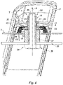
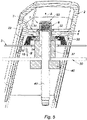
- the insert 1 is intended to be crimped on a part 2 to be fixed on a support 3, as illustrated in figure 4 and 5 .
- the insert 1 makes it possible to fix the part 2 to the support 3.
- the part 2 and the support 3 can be made of metal or a composite material, such as thermoplastic and/or thermosetting materials.
- the insert 1 can be a nut or a stud.
- a nut is a threaded hollow part, that is to say which has an internal thread, intended to be fixed to another threaded part.
- a stud is a full threaded part, that is to say which has an external thread.
- the insert 1 comprises a bearing head 4, a body 5, and a seal 6.
- the body 5 is hollow and has a cylindrical shape.
- cylinder is meant here a solid bounded by a cylindrical surface generated by a straight line, denoted generator, traversing a closed plane curve, denoted directrix, and two parallel planes intersecting the generatrices.
- Body 5 extends from bearing head 4 along a longitudinal axis A of insert 1 in a first direction.
- the body 5 comprises a crimping section 7 intended to be deformed during a crimping operation of the insert 1 on the part 2.
- the body 5 can also comprise a threaded section 8 located at one end of the body 5 opposite that where the support head 4 is located. In this case the insert 1 is a nut.
- the crimping section 7 is located between the threaded section 8 and the support head 4.
- the threaded section 8 has an internal thread 9 configured to receive a threaded rod.
- the bearing head 4 comprises an orifice 10 coinciding with the hollow of the body 5 of the insert 1.
- the insert 1 is preferably made of metal, for example steel, stainless or not, or aluminum.
- the support head 4 and the body 5 form a single piece.
- the seal 6 is integral with the support head 4, that is to say it is mechanically coupled with the support head 4.
- the seal 6, the support head 4 and the body 5 form a single element whose parts are held together without the intervention of an external part.
- Seal 6 cannot be lost when insert 1 is used.
- Seal 6 is located on bearing head 4. It is intended to cooperate with support 3 so as to provide a seal between the insert 1 and support 3, as shown in figure 4 and 5 .
- the seal 6 is deformable when the part to be fixed 2 exerts a constraining force on the insert 1, or vice versa, in order to provide the desired seal.
- the seal 6 is made of a material different from that of the bearing head 4 and of the body 5 of the insert 1.
- the seal 6 is made of a deformable material, for example of olefinic thermoplastic elastomer vulcanized, or ethylene-propylene-diene monomer, or nitrile butadiene rubber, or epichlorohydrin rubber, or polysiloxane polymer silicone rubber.
- the gasket 6 is molded onto the end of the bearing head 4, that is to say that the gasket 6 is formed by injecting a hardenable fluid, such as the aforementioned plastics, onto the bearing head 4.
- the support head 4 comprises a first shoulder 11 which acts as a support against the part 2 to crimp the insert 1, and a second shoulder 12 which cooperates with the seal 6 to keep it integral with the head of press 4. This avoids the assembly of seal 6 on the production line and the presence of seal 6 on insert 1 is guaranteed.
- the seal 6 comprises a base 13 having a parallelepipedal shape and at least one lip 14 to 16 extending in a second direction B opposite the first direction A.
- the lips 14 to 16 are oriented parallel to the longitudinal axis A of the insert 1, and in a direction opposite to that of the body 5 of the insert 1.
- the seal 6 may comprise a single lip 16, denoted outer lip, to lighten the insert 1 , or more lips 14 to 16 to improve sealing.
- the seal 6 comprises three lips 14 to 16, as illustrated in figures 1 to 5 .
- the lips 14 to 16 protrude from a first face 17 of the base 13.
- each lip 14 to 16 has the shape of a continuous crown surrounding the longitudinal axis A of the insert 1, that is to say say surrounding the orifice 10 of the bearing head 4.
- the seal 6 comprises two first internal lips 14 and 15 and a third external lip 16. The external lip 16 is located on the outermost part of the periphery, on the edge of the first face 17.
- the external lip 16 has an inner face 18 inclined at an angle of between 40° and 50° relative to the longitudinal axis A.
- the inner face 18 is located opposite the longitudinal axis A.
- the outer lip 16 may further comprise a external face 19, opposite internal face 18, inclined at an angle of between 120° and 125° relative to longitudinal axis A.
- External face 19 is located facing the outside relative to insert 1
- the inner lips 14 and 15 preferably have faces that are angled differently from those of the outer lip 16.
- each internal lip 14 and 15 may have an internal face 20, that is to say a face located opposite the longitudinal axis A, inclined at an angle of between 30° and 40°, favoring their deformation towards the outside to create a pressing effect against the support 3 in order to provide a seal with the support 3.
- each internal lip 14 and 15 may comprise an external face 21 located parallel to the longitudinal axis.
- the outer face 21 of an inner lip 14 and 15 is located facing the outside or even facing the inner face 20, 18 of another adjacent lip.
- the shape of the lips allows the lips 14 to 16 to deform under a force of 25 daN and provides effective sealing with the support 3.
- the shape of the outer lip 16, described above promotes a pronounced expansion towards the outside because the thickness of the outer lip 16 is less than that of the inner lips 14 and 15.
- the greater deformation of the outer lip 16 at least makes it possible to guarantee sealing against dust.
- the height of a lip 14 to 16 can be equal to twice its compression stroke.
- the deformation of the lips 14 to 16 is also favored by a space located between two adjacent lips.
- the lips 14 to 16 thus avoid generating compression forces prejudicial to the integrity of the seal 6. Finally, the lips 14 to 16 make it possible to deform the seal 6 without creating significant forces that risk damaging the support 3. By moreover, a bending of the support 3 could lead to a loss of tightness.
- the seal 6 is therefore particularly suitable for supports 3 which do not accept a pressure greater than 25 daN locally.
- the insert 1 may comprise a crown 22 projecting from the seal 6 and extending along the first direction A, the crown 22 being intended to provide a seal between the insert 1 and the part to be fixed 2.
- the crown 22 is located on a second face of the base 13, opposite the first face 17.
- the insert 1 is particularly suitable for attaching a bar 2 to a flag 3.
- the bar 2 corresponds to the part to be fixed 2 and the flag 3 corresponds to the support 3.
- a fixing assembly 50 comprising such an insert 1.
- the bell 3 has, for example, a thin thickness, that is to say a thickness less than 1 mm, preferably between 0.5 and 1 mm, for which the insert 1 is particularly suitable.
- the bell 3 can also be fixed to a reinforcement 30. In both embodiments, the insert 1 is crimped onto the bar 2.
- the crimping operation consists in introducing the insert 1 into an orifice of the bar 2 , then to deform the crimping section 7 along the longitudinal axis A.
- the crimping section 7 is configured to deform radially with respect to the longitudinal axis A into a crimping bead 31.
- radially is meant any direction located in a plane perpendicular to the longitudinal axis A.
- the crimping bead 31 comes into contact with a first face 32 of the bar 2 to crimp the insert 1 to the bar 2.
- the crimping bead 31 wedges the bar 2 with the bearing head 4, and more particularly with the first shoulder 11, to fix the insert 1 to the bar 2.
- the first face 32 of the bar 2 can be inaccessible and we say that the insert 1 is mounted blind on the bar 2.
- the support head 4 is intended to come into contact with a second face 33 of the bar 2 to jam the bar 2 with the crimping bead 31.
- the insert 1 is a nut intended to cooperate with a screw 34.
- the screw 34 comprises a threaded rod 35 and a screw head 36.
- the assembly of binding 50 further comprises the threaded rod 35 inserted into the internal thread 9 of the threaded section 8 of the insert 1.
- a spacer 37 can be placed between the head of support 4 and the reinforcement 30. The spacer 37 then bears against the support head 4. Then, the screw 34 tightens the fixing assembly 50, via the screw head 36 which bears against the reinforcement 30 to wedge the reinforcement 30 between the spacer 37 and the screw head 36.
- the insert 1 is a stud intended to cooperate with a locking nut 40.
- the fixing assembly 50 further comprises a threaded rod 41 at the level of its two ends.
- the threaded rod 41 can be introduced into the internal thread 9 of the threaded section 8 of the insert 1, or be fixed to the body 5 of the insert 1 by other means. Then, the locking nut 40 tightens the fixing assembly 50, bearing against the reinforcement 30 to wedge the reinforcement 30 between the spacer 37 and the locking nut 40.
- the sealing provided by the seal 6 is achieved during the compression of the seal 6, in particular at the level of the lips 14 to 16 and of the ring 22, by elastic dissipation of the seal 6.
- the seal between part 2 and insert 1 is improved by the force provided by crimping.
- the seal between the support 3 and the insert 1 is ensured by the compression and the deformation of the lips 14 to 16.
- Such an insert 1 makes it possible to provide sufficient sealing, for example when water is injected under a pressure of 110 bars, with a fixing force of around 25 daN at the point of fixing on the roof 3.
- the invention which has just been described makes it possible to provide an insert integrating an attachment interface and a sealing zone.
- Such an insert is particularly suitable for fixing a workpiece to a support, providing a seal with the support on which it is mounted, without deforming the support.
Landscapes
- Engineering & Computer Science (AREA)
- General Engineering & Computer Science (AREA)
- Mechanical Engineering (AREA)
- Gasket Seals (AREA)
- Insertion Pins And Rivets (AREA)
Description
- L'invention concerne les inserts à sertir sur une pièce à fixer sur un support, plus particulièrement les écrous et les goujons, et les ensembles de fixation comprenant de tels inserts.
- Il existe des inserts à sertir pour fixer différents éléments de carrosserie ou d'accessoires extérieurs de carrosserie. Un insert à sertir comporte une tête d'appui et un tronçon de sertissage déformable par traction selon un axe longitudinal de l'insert, de manière à former un bourrelet de sertissage destiné à fixer l'insert à une pièce, en coinçant la pièce entre la tête d'appui de l'insert et le bourrelet de sertissage ainsi formé.
- Par exemple, dans le secteur de l'automobile, on peut avoir besoin de fixer des barres sur le toit des véhicules, appelé également pavillon. Par ailleurs, il est nécessaire de garantir une étanchéité entre le pavillon et les inserts servant à fixer les barres, afin de protéger l'habitacle du véhicule. Actuellement, l'étanchéité entre les inserts et le pavillon est réalisée à l'aide d'une mousse à cellules fermées. Mais ces mousses ne sont pas adaptées pour résister à un appareil de lavage haute pression de l'ordre de 110 bars. Par ailleurs, pour améliorer l'étanchéité, on peut compresser la mousse, mais il y a un risque d'engendrer une déformation du pavillon. En outre, une telle déformation peut survenir facilement lorsque le pavillon a une épaisseur fine, c'est-à-dire inférieure à 1 mm, ce qui est notamment le cas pour les véhicules actuels qui sont de plus en plus légers afin de diminuer les émissions en dioxyde de carbone.
- On peut citer la demande de brevet allemand
DE 102007040041 qui divulgue un écrou à sertir en aveugle sur un élément de carrosserie, comprenant une tête d'appui prolongée par un tronçon de sertissage. Mais un tel écrou n'assure pas une étanchéité suffisante entre l'écrou et l'élément de carrosserie. - La demande de brevet américain
US 2014/0097218 divulgue un écrou à sertir sur un rail, comportant une tête située contre un élément de compensation d'écart fixé par encliquetage dans un orifice d'un pavillon. L'élément de compensation permet de maintenir un écart spécifique entre le pavillon et une structure de renfort du pavillon. Mais l'étanchéité procurée par l'encliquetage de l'élément de compensation n'est pas non plus suffisante. -
DE 20 2012 008057 U1 divulgue un insert selon le préambule de la revendication 1. - L'objet de l'invention consiste à pallier les inconvénients cités ci-avant, et en particulier à fournir un insert à sertir sur une pièce à fixer sur un support permettant d'assurer une étanchéité efficace entre l'insert et le support et qui soit simple à fabriquer.
- Un autre objet de l'invention consiste à fournir un insert adapté pour fixer la pièce à un support dont l'épaisseur est particulièrement fine tout en garantissant une étanchéité entre l'insert et le support.
- Selon un aspect de l'invention, il est proposé un insert à sertir sur une pièce à fixer sur un support, comprenant une tête d'appui et un tronçon de sertissage destiné à être déformé lors d'une opération de sertissage de l'insert sur la pièce à fixer.
- L'insert comporte en outre un joint solidaire de la tête d'appui et destiné à coopérer avec le support de manière à fournir une étanchéité entre l'insert et le support.
- Un tel insert permet de fournir une étanchéité entre l'insert et le support sans engendrer de déformations sur le support.
- L'insert peut comprendre un tronçon taraudé pour recevoir une tige filetée.
- En variante, l'insert comprend une tige filetée.
- Le joint peut être moulé par injection sur la tête d'appui.
- Le tronçon de sertissage fait saillie de la tête d'appui en s'étendant selon une première direction et le joint comporte plusieurs lèvres s'étendant selon une deuxième direction opposée à la première direction.
- Une lèvre externe située à une périphérie du joint peut comporter une face interne inclinée selon un angle compris entre 40° et 50° par rapport à un axe longitudinal du tronçon de sertissage.
- La lèvre externe peut également comporter une face externe inclinée selon un angle compris entre 120° et 125° par rapport à l'axe longitudinal.
- Une lèvre interne peut comporter une face interne inclinée selon un angle compris entre 30° et 40° par rapport à l'axe longitudinal.
- La lèvre interne peut comporter une face externe située parallèlement à l'axe longitudinal.
- L'insert comprend une couronne faisant saillie du joint et s'étendant selon la première direction, la couronne étant destinée à fournir une étanchéité entre l'insert et la pièce à fixer.
- La tête d'appui comprend un épaulement formant une jonction avec le tronçon de sertissage, et la couronne fait saille de l'épaulement.
- La tête d'appui comprend une face opposée à l'épaulement, la face opposée délimitant une extrémité de l'insert, et ladite au moins une lèvre faisant saillie de la face opposée.
- Selon un autre aspect de l'invention, il est proposé un ensemble de fixation pour fixer une pièce sur un support comprenant un insert tel que défini ci-avant, l'insert comprenant un tronçon taraudé, et l'ensemble de fixation comportant une tige filetée introduite dans le tronçon taraudé.
- D'autres avantages et caractéristiques ressortiront plus clairement de la description qui va suivre de modes particuliers de réalisation de l'invention donnés à titre d'exemples non limitatifs et représentés aux dessins annexés, dans lesquels :
- la
figure 1 , illustre schématiquement une vue en perspective d'un mode de réalisation d'un insert à sertir selon l'invention ; - la
figure 2 , illustre de façon schématique une vue en coupe de l'insert à sertir de lafigure 1 ; - la
figure 3 , illustre schématiquement une vue de dessous de l'insert à sertir de lafigure 1 ; - les
figures 4 et5 , illustrent schématiquement des vues en coupe d'autres modes de réalisation d'un insert à sertir. - Sur les
figures 1 à 3 , on a représenté un insert 1 à sertir. L'insert 1 est destiné à être serti sur une pièce 2 à fixer sur un support 3, comme illustré auxfigures 4 et5 . En d'autres termes, après sertissage de l'insert 1 sur la pièce 2, l'insert 1 permet de fixer la pièce 2 au support 3. La pièce 2 et le support 3 peuvent être en métal ou en matériau composite, comme des matériaux thermoplastiques et/ou thermodurcissables. L'insert 1 peut être un écrou ou un goujon. Un écrou est une pièce creuse taraudée, c'est-à-dire qui comporte un filetage interne, destinée à être fixée à une autre pièce filetée. Un goujon est une pièce pleine filetée, c'est-à-dire qui comporte un filetage externe. - L'insert 1 comporte une tête d'appui 4, un corps 5, et un joint 6. Le corps 5 est creux et a une forme cylindrique. On entend ici par cylindre, un solide limité par une surface cylindrique engendrée par une droite, notée génératrice, parcourant une courbe plane fermée, notée directrice, et deux plans parallèles coupant les génératrices. Le corps 5 s'étend depuis la tête d'appui 4 le long d'un axe longitudinal A de l'insert 1 selon une première direction. Le corps 5 comporte un tronçon de sertissage 7 destiné à être déformé lors d'une opération de sertissage de l'insert 1 sur la pièce 2. Le corps 5 peut également comporter un tronçon taraudé 8 situé à une extrémité du corps 5 opposée à celle où est située la tête d'appui 4. Dans ce cas l'insert 1 est un écrou. En d'autres termes, le tronçon de sertissage 7 est situé entre le tronçon taraudé 8 et la tête d'appui 4. Le tronçon taraudé 8 comporte un filetage interne 9 configuré pour recevoir une tige filetée. Plus particulièrement, la tête d'appui 4 comporte un orifice 10 coïncidant avec le creux du corps 5 de l'insert 1. L'insert 1 est de préférence en métal, par exemple en acier, inoxydable ou non, ou en aluminium. Avantageusement, la tête d'appui 4 et le corps 5 forment une seule pièce.
- Le joint 6 est solidaire de la tête d'appui 4, c'est-à-dire qu'il est couplé mécaniquement avec la tête d'appui 4. En d'autres termes le joint 6, la tête d'appui 4 et le corps 5 forment un seul élément dont les parties sont maintenues ensembles sans l'intervention d'une pièce extérieure. Ainsi, on ne peut pas perdre le joint 6 lorsqu'on utilise l'insert 1. Le joint 6 est situé sur la tête d'appui 4. Il est destiné à coopérer avec le support 3 de manière à fournir une étanchéité entre l'insert 1 et le support 3, comme illustré aux
figures 4 et5 . Le joint 6 est déformable lorsque la pièce à fixer 2 exerce une force de contrainte sur l'insert 1, ou inversement, afin de fournir l'étanchéité recherchée. Préférentiellement, le joint 6 est réalisé dans un matériau différent de celui de la tête d'appui 4 et du corps 5 de l'insert 1. De façon générale, le joint 6 est réalisé dans un matériau déformable, par exemple en élastomère thermoplastique oléfinique vulcanisé, ou en éthylène-propylène-diène monomère, ou en caoutchouc nitrile butadiène, ou en caoutchouc épichlorohydrine, ou encore en caoutchouc silicone polymère polysiloxane. Le joint 6 est surmoulé sur l'extrémité de la tête d'appui 4, c'est-à-dire que le joint 6 est formé par injection d'un fluide durcissable, tels que les plastiques précités, sur la tête d'appui 4. La tête d'appui 4 comporte un premier épaulement 11 qui fait office d'appui contre la pièce 2 pour sertir l'insert 1, et un deuxième épaulement 12 qui coopère avec le joint 6 pour le maintenir solidaire avec la tête d'appui 4. Ainsi, on évite le montage du joint 6 en ligne de production et on garantit la présence du joint 6 sur l'insert 1. - De manière générale, le joint 6 comporte une base 13 ayant une forme parallélépipédique et au moins une lèvre 14 à 16 s'étendant selon une deuxième direction B opposée à la première direction A. En d'autres termes, les lèvres 14 à 16 sont orientées parallèlement à l'axe longitudinale A de l'insert 1, et selon un sens opposé à celle du corps 5 de l'insert 1. Le joint 6 peut comprendre une seule lèvre 16, notée lèvre externe, pour alléger l'insert 1, ou plusieurs lèvres 14 à 16 pour améliorer l'étanchéité. Selon un mode de réalisation préféré, le joint 6 comporte trois lèvres 14 à 16, comme illustré aux
figures 1 à 5 . Les lèvres 14 à 16 font saillie d'une première face 17 de la base 13. Avantageusement, les lèvres 14 à 16 sont situées sur le bord externe de la première face 17 afin de dégager une zone autour de l'orifice 10 de la tête d'appui 4, notamment pour placer une entretoise contre la tête d'appui 4, comme illustré sur lesfigures 4 et5 . On dit également que les lèvres 14 à 16 sont situées à la périphérie du joint 6. Par exemple, chaque lèvre 14 à 16 a une forme de couronne continue entourant l'axe longitudinal A de l'insert 1, c'est-à-dire entourant l'orifice 10 de la tête d'appui 4. Sur lesfigures 1 à 5 , le joint 6 comporte deux premières lèvres internes 14 et 15 et une troisième lèvre externe 16. La lèvre externe 16 est située sur la partie la plus externe de la périphérie, sur le bord de la première face 17. Plus particulièrement, la lèvre externe 16 comporte une face interne 18 inclinée selon un angle compris entre 40° et 50° par rapport à l'axe longitudinal A. La face interne 18 est située en regard de l'axe longitudinal A. La lèvre externe 16 peut en outre comprendre une face externe 19, opposée à la face interne 18, inclinée selon un angle compris entre 120° et 125° par rapport à l'axe longitudinal A. La face externe 19 est située en regard de l'extérieur par rapport à l'insert 1. En outre, les lèvres internes 14 et 15 ont, de préférence, des faces inclinées différemment par rapport à celles de la lèvre externe 16. Par exemple, chaque lèvre interne 14 et 15 peut avoir une face interne 20, c'est-à-dire une face située en regard de l'axe longitudinal A, inclinée selon un angle compris entre 30° et 40°, favorisant leur déformation vers l'extérieur pour créer un effet de plaquage contre le support 3 afin de fournir une étanchéité avec le support 3. Selon un autre exemple, chaque lèvre interne 14 et 15 peut comporter une face externe 21 située parallèlement à l'axe longitudinal. La face externe 21 d'une lèvre interne 14 et 15 est située en regard de l'extérieur ou encore en regard de la face interne 20, 18 d'une autre lèvre adjacente. La forme des lèvres permet aux lèvres 14 à 16 de se déformer sous un effort de 25 daN et assure une étanchéité efficace avec le support 3. Par ailleurs, la forme de la lèvre externe 16, décrite ci-avant, favorise une expansion prononcée vers l'extérieur car l'épaisseur de la lèvre externe 16 est inférieure à celles des lèvres internes 14 et 15. La déformation plus importante de la lèvre externe 16 permet au moins de garantir une étanchéité contre les poussières. La hauteur d'une lèvre 14 à 16 peut être égale au double de sa course de compression. La déformation des lèvres 14 à 16 est en outre favorisée par un espace situé entre deux lèvres adjacentes. Les lèvres 14 à 16 évitent ainsi de générer des forces de compression préjudiciables à l'intégrité du joint 6. Enfin, les lèvres 14 à 16 permettent de déformer le joint 6 sans créer d'efforts importants risquant d'endommager le support 3. Par ailleurs, une flexion du support 3 pourrait entraîner une perte d'étanchéité. Le joint 6 est donc particulièrement adapté pour des supports 3 qui n'acceptent pas une pression supérieure à 25 daN localement. - En outre, l'insert 1 peut comprendre une couronne 22 faisant saillie du joint 6 et s'étendant selon la première direction A, la couronne 22 étant destinée à fournir une étanchéité entre l'insert 1 et la pièce à fixer 2. La couronne 22 est située sur une deuxième face de la base 13, opposée à la première face 17.
- Sur les
figures 4 et5 , on a représenté deux modes de réalisation de l'insert 1 particulièrement adaptés pour fixer une barre 2 à un pavillon 3. La barre 2 correspond à la pièce à fixer 2 et le pavillon 3 correspond au support 3. On a également illustré sur lesfigures 4 et5 un ensemble de fixation 50 comprenant un tel insert 1. Le pavillon 3 a, par exemple, une épaisseur fine, c'est-à-dire une épaisseur inférieure à 1 mm, de préférence comprise entre 0,5 et 1 mm, pour lequel l'insert 1 est particulièrement adapté. Le pavillon 3 peut en outre être fixé à un renfort 30. Dans les deux modes de réalisation, l'insert 1 est serti sur la barre 2. L'opération de sertissage consiste à introduire l'insert 1 dans un orifice de la barre 2, puis à déformer le tronçon de sertissage 7 selon l'axe longitudinal A. Le tronçon de sertissage 7 est configuré pour se déformer radialement par rapport à l'axe longitudinal A en un bourrelet de sertissage 31. On entend par radialement, toute direction située dans un plan perpendiculaire à l'axe longitudinal A. Le bourrelet de sertissage 31 vient au contact d'une première face 32 de la barre 2 pour sertir l'insert 1 à la barre 2. En d'autres termes, le bourrelet de sertissage 31 coince la barre 2 avec la tête d'appui 4, et plus particulièrement avec le premier épaulement 11, pour fixer l'insert 1 à la barre 2. Par exemple, la première face 32 de la barre 2 peut être inaccessible et on dit que l'insert 1 est monté en aveugle sur la barre 2. La tête d'appui 4 est destinée à venir au contact d'une deuxième face 33 de la barre 2 pour coincer la barre 2 avec le bourrelet de sertissage 31. - Sur la
figure 4 , on a représenté un mode de réalisation dans lequel l'insert 1 est un écrou destiné à coopérer avec une vis 34. La vis 34 comporte une tige filetée 35 et une tête de vis 36. Dans ce mode de réalisation, l'ensemble de fixation 50 comprend en outre la tige filetée 35 introduite dans le filetage interne 9 du tronçon taraudé 8 de l'insert 1. Afin de maintenir un écartement spécifique entre le pavillon 3 et le renfort 30, on peut placer une entretoise 37 entre la tête d'appui 4 et le renfort 30. L'entretoise 37 prend alors appui contre la tête d'appui 4. Puis, la vis 34 serre l'ensemble de fixation 50, par l'intermédiaire de la tête de vis 36 qui prend appui contre le renfort 30 pour coincer le renfort 30 entre l'entretoise 37 et la tête de vis 36. - Sur la
figure 5 , on a représenté un autre mode de réalisation dans lequel l'insert 1 est un goujon destiné à coopérer avec un écrou de blocage 40. Dans ce mode de réalisation, l'ensemble de fixation 50 comprend en outre une tige filetée 41 au niveau de ses deux extrémités. La tige filetée 41 peut être introduite dans le filetage interne 9 du tronçon taraudé 8 de l'insert 1, ou être fixée au corps 5 de l'insert 1 selon d'autres moyens. Puis, l'écrou de blocage 40 serre l'ensemble de fixation 50, en prenant appui contre le renfort 30 pour coincer le renfort 30 entre l'entretoise 37 et l'écrou de blocage 40. - Dans les deux modes de réalisation illustré aux
figures 4 et5 , l'étanchéité fournie par le joint 6 est réalisée lors de la compression du joint 6, en particulier au niveau des lèvres 14 à 16 et de la couronne 22, par dissipation élastique du joint 6. En d'autres termes, on assure une étanchéité entre, d'une part le pavillon 3 et l'insert 1 à l'aide des lèvres 14 à 16 du joint 6, et d'autre part la barre 2 et l'insert 1 à l'aide de la couronne 22 du joint 6. En particulier, l'étanchéité entre la pièce 2 et l'insert 1 est améliorée par l'effort fourni par le sertissage. L'étanchéité entre le support 3 et l'insert 1 est assurée par la compression et la déformation des lèvres 14 à 16. - Un tel insert 1 permet de fournir une étanchéité suffisante, par exemple lorsque de l'eau est injectée sous une pression de 110 bars, avec une force de fixation d'environ 25 daN au point de fixation sur le pavillon 3.
- L'invention qui vient d'être décrite permet de fournir un insert intégrant une interface de fixation et une zone d'étanchéité. Un tel insert est particulièrement adapté pour fixer une pièce sur un support, en fournissant une étanchéité avec le support sur lequel il est monté, sans déformer le support.
Claims (8)
- Insert à sertir sur une pièce (2) à fixer sur un support (3), comprenant :- une tête d'appui (4),- un tronçon de sertissage (7) destiné à être déformé lors d'une opération de sertissage de l'insert sur la pièce (2) à fixer, le tronçon de sertissage (7) faisant saillie de la tête d'appui (4) en s'étendant selon une première direction (A),- un joint (6) solidaire de la tête d'appui (4) et destiné à coopérer avec le support (3) de manière à fournir une étanchéité entre l'insert et le support (3), le joint (6) comportant plusieurs lèvres (14 à 16) s'étendant selon une deuxième direction (B) opposée à la première direction (A) avec une lèvre externe située à la périphérie du joint (6),caractérisé en ce que la tête d'appui (4) comporte un épaulement (11) formant une jonction avec le tronçon de sertissage (7) et une face opposée à l'épaulement (11), la face opposée délimitant une extrémité de l'insert, en ce que les lèvres (14 à 16) font saillie de la face opposée, et en ce que le joint (6) comporte une couronne (22) faisant saillie du joint (6) en s'étendant selon la première direction (A), la couronne (22) étant destinée à fournir une étanchéité entre l'insert et la pièce (2) à fixer, la couronne (22) faisant saillie de l'épaulement (11).
- Insert selon la revendication 1, comprenant un tronçon taraudé (8) pour recevoir une tige filetée (35, 41).
- Insert selon la revendication 1 ou 2, dans lequel le joint (6) est moulé par injection sur la tête d'appui (4).
- Insert selon la revendication 1, dans lequel la lèvre externe (16) située à une périphérie du joint (6) comporte une face interne (18) inclinée selon un angle compris entre 40° et 50° par rapport à un axe longitudinal (A) du tronçon de sertissage (7).
- Insert selon la revendication 4, dans lequel la lèvre externe (16) comporte une face externe (19) inclinée selon un angle compris entre 120° et 125° par rapport à l'axe longitudinal (A).
- Insert selon la revendication 4 ou 5, dans lequel une lèvre interne (14, 15) comporte une face interne (20) inclinée selon un angle compris entre 30° et 40° par rapport à l'axe longitudinal (A).
- Insert selon la revendication 6, dans lequel la lèvre interne (14, 15) comporte une face externe (21) située parallèlement à l'axe longitudinal (A).
- Ensemble de fixation pour fixer une pièce (2) sur un support (3) comprenant un insert selon l'une des revendications 1 à 7, l'insert comprenant un tronçon taraudé (8), et l'ensemble de fixation comportant une tige filetée (35, 41) introduite dans le tronçon taraudé (8).
Applications Claiming Priority (1)
| Application Number | Priority Date | Filing Date | Title |
|---|---|---|---|
| FR1551718A FR3033183B1 (fr) | 2015-02-27 | 2015-02-27 | Insert a sertir sur une piece a fixer sur un support et ensemble de fixation comprenant un tel insert |
Publications (2)
| Publication Number | Publication Date |
|---|---|
| EP3061979A1 EP3061979A1 (fr) | 2016-08-31 |
| EP3061979B1 true EP3061979B1 (fr) | 2022-04-06 |
Family
ID=52991812
Family Applications (1)
| Application Number | Title | Priority Date | Filing Date |
|---|---|---|---|
| EP15189651.1A Active EP3061979B1 (fr) | 2015-02-27 | 2015-10-13 | Insert à sertir sur une pièce à fixer sur un support et ensemble de fixation comprenant un tel insert |
Country Status (3)
| Country | Link |
|---|---|
| EP (1) | EP3061979B1 (fr) |
| CN (1) | CN105370696B (fr) |
| FR (1) | FR3033183B1 (fr) |
Families Citing this family (2)
| Publication number | Priority date | Publication date | Assignee | Title |
|---|---|---|---|---|
| US11872959B2 (en) * | 2019-07-08 | 2024-01-16 | Lacks Enterprises, Inc. | Automotive roof rail system |
| JP2024107705A (ja) * | 2023-01-30 | 2024-08-09 | 株式会社Subaru | 車両用ルーフレール構造 |
Citations (2)
| Publication number | Priority date | Publication date | Assignee | Title |
|---|---|---|---|---|
| FR2569792A1 (fr) * | 1984-09-03 | 1986-03-07 | Otalu Sa | Rivet tubulaire taraude etanche |
| EP1389691A1 (fr) * | 2002-08-05 | 2004-02-18 | EJOT GmbH & Co. KG | Ecrou en plastique pour monter à un élément de construction |
Family Cites Families (8)
| Publication number | Priority date | Publication date | Assignee | Title |
|---|---|---|---|---|
| FR953599A (fr) * | 1946-11-29 | 1949-12-08 | Goodrich Co B F | Perfectionnements apportés aux dispositifs d'étanchéité pour les joints formés entre des rivets tubulaires et l'ouvrage qui les supporte |
| JP2940898B2 (ja) * | 1993-05-14 | 1999-08-25 | 永山電子工業 株式会社 | Tナット |
| GB0107664D0 (en) * | 2001-03-28 | 2001-05-16 | Emhart Inc | Blind rivet nut with improved seal retention |
| DE202007012400U1 (de) * | 2007-04-19 | 2008-08-21 | Voss Automotive Gmbh | Anschlussvorrichtung für Medienleitungen im Bereich einer Wandungsdurchführung sowie Wandungselement |
| DE102007040041A1 (de) | 2007-08-24 | 2009-02-26 | Audi Ag | Verbindungsanordnung zur Verschiebesicherung eines Fahrzeuganbauteils und zugehörige Befestigungsanordnung für ein Fahrzeuganbauteil |
| FR2938310B1 (fr) * | 2008-11-07 | 2013-05-17 | Raymond A & Cie | Agrafe de fixation avec rondelle d'etancheite |
| FR2979401B1 (fr) * | 2011-08-26 | 2014-10-24 | Bollhoff Otalu Sa | Dispositif a sertir pour fixer un element en plastique, et installation mettant en oeuvre ledit dispositif |
| EP2716500B1 (fr) | 2012-10-04 | 2016-12-07 | Dura Operating, LLC | Longeron de toit avec système de fixation |
-
2015
- 2015-02-27 FR FR1551718A patent/FR3033183B1/fr active Active
- 2015-10-13 EP EP15189651.1A patent/EP3061979B1/fr active Active
- 2015-10-27 CN CN201510706125.0A patent/CN105370696B/zh active Active
Patent Citations (2)
| Publication number | Priority date | Publication date | Assignee | Title |
|---|---|---|---|---|
| FR2569792A1 (fr) * | 1984-09-03 | 1986-03-07 | Otalu Sa | Rivet tubulaire taraude etanche |
| EP1389691A1 (fr) * | 2002-08-05 | 2004-02-18 | EJOT GmbH & Co. KG | Ecrou en plastique pour monter à un élément de construction |
Also Published As
| Publication number | Publication date |
|---|---|
| FR3033183B1 (fr) | 2017-09-01 |
| CN105370696A (zh) | 2016-03-02 |
| FR3033183A1 (fr) | 2016-09-02 |
| EP3061979A1 (fr) | 2016-08-31 |
| CN105370696B (zh) | 2018-10-12 |
Similar Documents
| Publication | Publication Date | Title |
|---|---|---|
| EP3366932B1 (fr) | Insert à sertir, élément et ensemble de fixation comprenant un tel insert et procédés de fabrication de telles pièces | |
| FR2740526A1 (fr) | Joint d'etancheite composite pour raccordement etanche entre une extremite de tube et une piece, et ensemble piece/tube comportant un tel joint | |
| EP2352928B1 (fr) | Agrafe de fixation avec rondelle d'étanchéité | |
| FR2862430A1 (fr) | Structure de fixation de batterie d'accumulateurs pour vehicule | |
| EP3186126B1 (fr) | Système d'étanchéité pour un ouvrant comportant un profile recevant un joint d'étanchéité verrouille par une clé coulissante | |
| EP3061979A1 (fr) | Insert à sertir sur une pièce à fixer sur un support et ensemble de fixation comprenant un tel insert | |
| WO2009043980A1 (fr) | Connecteur pour raccorder deux extremites creuses de profile | |
| EP3199405B1 (fr) | Barre de toit pour véhicule automobile et système de fixation associé | |
| FR2945088A1 (fr) | Systeme d'ecrou noye a sertir en aveugle avec axe ajustable | |
| FR2979401A1 (fr) | Dispositif a sertir pour fixer un element en plastique, et installation mettant en oeuvre ledit dispositif | |
| FR2575979A1 (fr) | Dispositif pour realiser une fixation etanche d'un organe sur une paroi, notamment une tole de carrosserie automobile et application d'un tel dispositif a la fixation d'accessoires automobiles, en particulier a la fixation d'une embase d'antenne | |
| EP3969663B1 (fr) | Joint de dilatation carrossable | |
| EP0625636B1 (fr) | Pièce métallique creuse pourvue d'un joint d'étanchéité, telle qu'un carter inferieur de moteur de véhicule automobile | |
| BE1032552B1 (fr) | Réservoir à carburant en matière plastique pour véhicule automobile | |
| EP3491324B1 (fr) | Boite collectrice, moyen d'etancheite et echangeur thermique correspondant | |
| FR2976544A1 (fr) | Agencement de deux pieces, notamment de vehicule automobile, assemblees l'une a l'autre par deux de leurs parois superposees, de facon etanche | |
| EP2463531B1 (fr) | Ecrou de blocage et dispositif de serrage équipé dudit écrou | |
| FR2962187A1 (fr) | Dispositif et procede de raccordement en particulier pour circuit de refroidissement d'eau de vehicule automobile. | |
| FR2575427A1 (fr) | Dispositif pour realiser une fixation etanche d'un organe sur une paroi, notamment une tole de carrosserie automobile et appplication d'un tel dispositif a la fixation d'accessoires automobiles, en particulier a la fixation d'une embase d'antenne | |
| FR2900218A1 (fr) | Connecteur pour raccorder deux extremites creuses de profile | |
| EP2800678B1 (fr) | Joint d'etancheite lineaire et agencement d'un tel joint entre une garniture de porte et un haut-parleur de vehicule automobile | |
| FR3007495A1 (fr) | Ensemble pour la realisation d'un joint filete pour le forage et l'exploitation des puits d'hydrocarbures, joint filete et procede de realisation d'un tel joint | |
| FR3036362A1 (fr) | Systeme de fixation ameliore | |
| FR2869387A1 (fr) | Connecteur pour raccorder deux extremites creuses de profile | |
| FR2555634A3 (fr) | Calotte de repartition de charge a mettre en place pour la fixation par vis d'un revetement profile de toit ou de paroi |
Legal Events
| Date | Code | Title | Description |
|---|---|---|---|
| PUAI | Public reference made under article 153(3) epc to a published international application that has entered the european phase |
Free format text: ORIGINAL CODE: 0009012 |
|
| AK | Designated contracting states |
Kind code of ref document: A1 Designated state(s): AL AT BE BG CH CY CZ DE DK EE ES FI FR GB GR HR HU IE IS IT LI LT LU LV MC MK MT NL NO PL PT RO RS SE SI SK SM TR |
|
| AX | Request for extension of the european patent |
Extension state: BA ME |
|
| STAA | Information on the status of an ep patent application or granted ep patent |
Free format text: STATUS: REQUEST FOR EXAMINATION WAS MADE |
|
| 17P | Request for examination filed |
Effective date: 20170215 |
|
| RBV | Designated contracting states (corrected) |
Designated state(s): AL AT BE BG CH CY CZ DE DK EE ES FI FR GB GR HR HU IE IS IT LI LT LU LV MC MK MT NL NO PL PT RO RS SE SI SK SM TR |
|
| STAA | Information on the status of an ep patent application or granted ep patent |
Free format text: STATUS: EXAMINATION IS IN PROGRESS |
|
| 17Q | First examination report despatched |
Effective date: 20171103 |
|
| GRAP | Despatch of communication of intention to grant a patent |
Free format text: ORIGINAL CODE: EPIDOSNIGR1 |
|
| STAA | Information on the status of an ep patent application or granted ep patent |
Free format text: STATUS: GRANT OF PATENT IS INTENDED |
|
| INTG | Intention to grant announced |
Effective date: 20210210 |
|
| GRAJ | Information related to disapproval of communication of intention to grant by the applicant or resumption of examination proceedings by the epo deleted |
Free format text: ORIGINAL CODE: EPIDOSDIGR1 |
|
| STAA | Information on the status of an ep patent application or granted ep patent |
Free format text: STATUS: EXAMINATION IS IN PROGRESS |
|
| INTC | Intention to grant announced (deleted) | ||
| RAP3 | Party data changed (applicant data changed or rights of an application transferred) |
Owner name: BOLLHOFF OTALU |
|
| GRAS | Grant fee paid |
Free format text: ORIGINAL CODE: EPIDOSNIGR3 |
|
| STAA | Information on the status of an ep patent application or granted ep patent |
Free format text: STATUS: GRANT OF PATENT IS INTENDED |
|
| GRAP | Despatch of communication of intention to grant a patent |
Free format text: ORIGINAL CODE: EPIDOSNIGR1 |
|
| INTG | Intention to grant announced |
Effective date: 20211122 |
|
| GRAA | (expected) grant |
Free format text: ORIGINAL CODE: 0009210 |
|
| STAA | Information on the status of an ep patent application or granted ep patent |
Free format text: STATUS: THE PATENT HAS BEEN GRANTED |
|
| AK | Designated contracting states |
Kind code of ref document: B1 Designated state(s): AL AT BE BG CH CY CZ DE DK EE ES FI FR GB GR HR HU IE IS IT LI LT LU LV MC MK MT NL NO PL PT RO RS SE SI SK SM TR |
|
| REG | Reference to a national code |
Ref country code: GB Ref legal event code: FG4D Free format text: NOT ENGLISH |
|
| REG | Reference to a national code |
Ref country code: CH Ref legal event code: EP |
|
| REG | Reference to a national code |
Ref country code: AT Ref legal event code: REF Ref document number: 1481603 Country of ref document: AT Kind code of ref document: T Effective date: 20220415 |
|
| REG | Reference to a national code |
Ref country code: DE Ref legal event code: R096 Ref document number: 602015078001 Country of ref document: DE |
|
| REG | Reference to a national code |
Ref country code: IE Ref legal event code: FG4D Free format text: LANGUAGE OF EP DOCUMENT: FRENCH |
|
| REG | Reference to a national code |
Ref country code: LT Ref legal event code: MG9D |
|
| REG | Reference to a national code |
Ref country code: NL Ref legal event code: MP Effective date: 20220406 |
|
| REG | Reference to a national code |
Ref country code: AT Ref legal event code: MK05 Ref document number: 1481603 Country of ref document: AT Kind code of ref document: T Effective date: 20220406 |
|
| PG25 | Lapsed in a contracting state [announced via postgrant information from national office to epo] |
Ref country code: NL Free format text: LAPSE BECAUSE OF FAILURE TO SUBMIT A TRANSLATION OF THE DESCRIPTION OR TO PAY THE FEE WITHIN THE PRESCRIBED TIME-LIMIT Effective date: 20220406 |
|
| PG25 | Lapsed in a contracting state [announced via postgrant information from national office to epo] |
Ref country code: SE Free format text: LAPSE BECAUSE OF FAILURE TO SUBMIT A TRANSLATION OF THE DESCRIPTION OR TO PAY THE FEE WITHIN THE PRESCRIBED TIME-LIMIT Effective date: 20220406 Ref country code: PT Free format text: LAPSE BECAUSE OF FAILURE TO SUBMIT A TRANSLATION OF THE DESCRIPTION OR TO PAY THE FEE WITHIN THE PRESCRIBED TIME-LIMIT Effective date: 20220808 Ref country code: NO Free format text: LAPSE BECAUSE OF FAILURE TO SUBMIT A TRANSLATION OF THE DESCRIPTION OR TO PAY THE FEE WITHIN THE PRESCRIBED TIME-LIMIT Effective date: 20220706 Ref country code: LT Free format text: LAPSE BECAUSE OF FAILURE TO SUBMIT A TRANSLATION OF THE DESCRIPTION OR TO PAY THE FEE WITHIN THE PRESCRIBED TIME-LIMIT Effective date: 20220406 Ref country code: HR Free format text: LAPSE BECAUSE OF FAILURE TO SUBMIT A TRANSLATION OF THE DESCRIPTION OR TO PAY THE FEE WITHIN THE PRESCRIBED TIME-LIMIT Effective date: 20220406 Ref country code: GR Free format text: LAPSE BECAUSE OF FAILURE TO SUBMIT A TRANSLATION OF THE DESCRIPTION OR TO PAY THE FEE WITHIN THE PRESCRIBED TIME-LIMIT Effective date: 20220707 Ref country code: FI Free format text: LAPSE BECAUSE OF FAILURE TO SUBMIT A TRANSLATION OF THE DESCRIPTION OR TO PAY THE FEE WITHIN THE PRESCRIBED TIME-LIMIT Effective date: 20220406 Ref country code: ES Free format text: LAPSE BECAUSE OF FAILURE TO SUBMIT A TRANSLATION OF THE DESCRIPTION OR TO PAY THE FEE WITHIN THE PRESCRIBED TIME-LIMIT Effective date: 20220406 Ref country code: BG Free format text: LAPSE BECAUSE OF FAILURE TO SUBMIT A TRANSLATION OF THE DESCRIPTION OR TO PAY THE FEE WITHIN THE PRESCRIBED TIME-LIMIT Effective date: 20220706 Ref country code: AT Free format text: LAPSE BECAUSE OF FAILURE TO SUBMIT A TRANSLATION OF THE DESCRIPTION OR TO PAY THE FEE WITHIN THE PRESCRIBED TIME-LIMIT Effective date: 20220406 |
|
| PG25 | Lapsed in a contracting state [announced via postgrant information from national office to epo] |
Ref country code: RS Free format text: LAPSE BECAUSE OF FAILURE TO SUBMIT A TRANSLATION OF THE DESCRIPTION OR TO PAY THE FEE WITHIN THE PRESCRIBED TIME-LIMIT Effective date: 20220406 Ref country code: PL Free format text: LAPSE BECAUSE OF FAILURE TO SUBMIT A TRANSLATION OF THE DESCRIPTION OR TO PAY THE FEE WITHIN THE PRESCRIBED TIME-LIMIT Effective date: 20220406 Ref country code: LV Free format text: LAPSE BECAUSE OF FAILURE TO SUBMIT A TRANSLATION OF THE DESCRIPTION OR TO PAY THE FEE WITHIN THE PRESCRIBED TIME-LIMIT Effective date: 20220406 Ref country code: IS Free format text: LAPSE BECAUSE OF FAILURE TO SUBMIT A TRANSLATION OF THE DESCRIPTION OR TO PAY THE FEE WITHIN THE PRESCRIBED TIME-LIMIT Effective date: 20220806 |
|
| REG | Reference to a national code |
Ref country code: DE Ref legal event code: R097 Ref document number: 602015078001 Country of ref document: DE |
|
| PG25 | Lapsed in a contracting state [announced via postgrant information from national office to epo] |
Ref country code: SM Free format text: LAPSE BECAUSE OF FAILURE TO SUBMIT A TRANSLATION OF THE DESCRIPTION OR TO PAY THE FEE WITHIN THE PRESCRIBED TIME-LIMIT Effective date: 20220406 Ref country code: SK Free format text: LAPSE BECAUSE OF FAILURE TO SUBMIT A TRANSLATION OF THE DESCRIPTION OR TO PAY THE FEE WITHIN THE PRESCRIBED TIME-LIMIT Effective date: 20220406 Ref country code: RO Free format text: LAPSE BECAUSE OF FAILURE TO SUBMIT A TRANSLATION OF THE DESCRIPTION OR TO PAY THE FEE WITHIN THE PRESCRIBED TIME-LIMIT Effective date: 20220406 Ref country code: EE Free format text: LAPSE BECAUSE OF FAILURE TO SUBMIT A TRANSLATION OF THE DESCRIPTION OR TO PAY THE FEE WITHIN THE PRESCRIBED TIME-LIMIT Effective date: 20220406 Ref country code: DK Free format text: LAPSE BECAUSE OF FAILURE TO SUBMIT A TRANSLATION OF THE DESCRIPTION OR TO PAY THE FEE WITHIN THE PRESCRIBED TIME-LIMIT Effective date: 20220406 Ref country code: CZ Free format text: LAPSE BECAUSE OF FAILURE TO SUBMIT A TRANSLATION OF THE DESCRIPTION OR TO PAY THE FEE WITHIN THE PRESCRIBED TIME-LIMIT Effective date: 20220406 |
|
| PLBE | No opposition filed within time limit |
Free format text: ORIGINAL CODE: 0009261 |
|
| STAA | Information on the status of an ep patent application or granted ep patent |
Free format text: STATUS: NO OPPOSITION FILED WITHIN TIME LIMIT |
|
| 26N | No opposition filed |
Effective date: 20230110 |
|
| PG25 | Lapsed in a contracting state [announced via postgrant information from national office to epo] |
Ref country code: AL Free format text: LAPSE BECAUSE OF FAILURE TO SUBMIT A TRANSLATION OF THE DESCRIPTION OR TO PAY THE FEE WITHIN THE PRESCRIBED TIME-LIMIT Effective date: 20220406 |
|
| PG25 | Lapsed in a contracting state [announced via postgrant information from national office to epo] |
Ref country code: SI Free format text: LAPSE BECAUSE OF FAILURE TO SUBMIT A TRANSLATION OF THE DESCRIPTION OR TO PAY THE FEE WITHIN THE PRESCRIBED TIME-LIMIT Effective date: 20220406 Ref country code: MC Free format text: LAPSE BECAUSE OF FAILURE TO SUBMIT A TRANSLATION OF THE DESCRIPTION OR TO PAY THE FEE WITHIN THE PRESCRIBED TIME-LIMIT Effective date: 20220406 |
|
| REG | Reference to a national code |
Ref country code: CH Ref legal event code: PL |
|
| REG | Reference to a national code |
Ref country code: BE Ref legal event code: MM Effective date: 20221031 |
|
| PG25 | Lapsed in a contracting state [announced via postgrant information from national office to epo] |
Ref country code: LU Free format text: LAPSE BECAUSE OF NON-PAYMENT OF DUE FEES Effective date: 20221013 |
|
| PG25 | Lapsed in a contracting state [announced via postgrant information from national office to epo] |
Ref country code: LI Free format text: LAPSE BECAUSE OF NON-PAYMENT OF DUE FEES Effective date: 20221031 Ref country code: CH Free format text: LAPSE BECAUSE OF NON-PAYMENT OF DUE FEES Effective date: 20221031 |
|
| PG25 | Lapsed in a contracting state [announced via postgrant information from national office to epo] |
Ref country code: BE Free format text: LAPSE BECAUSE OF NON-PAYMENT OF DUE FEES Effective date: 20221031 |
|
| PG25 | Lapsed in a contracting state [announced via postgrant information from national office to epo] |
Ref country code: IE Free format text: LAPSE BECAUSE OF NON-PAYMENT OF DUE FEES Effective date: 20221013 |
|
| PG25 | Lapsed in a contracting state [announced via postgrant information from national office to epo] |
Ref country code: IT Free format text: LAPSE BECAUSE OF FAILURE TO SUBMIT A TRANSLATION OF THE DESCRIPTION OR TO PAY THE FEE WITHIN THE PRESCRIBED TIME-LIMIT Effective date: 20220406 |
|
| PG25 | Lapsed in a contracting state [announced via postgrant information from national office to epo] |
Ref country code: HU Free format text: LAPSE BECAUSE OF FAILURE TO SUBMIT A TRANSLATION OF THE DESCRIPTION OR TO PAY THE FEE WITHIN THE PRESCRIBED TIME-LIMIT; INVALID AB INITIO Effective date: 20151013 |
|
| PG25 | Lapsed in a contracting state [announced via postgrant information from national office to epo] |
Ref country code: CY Free format text: LAPSE BECAUSE OF FAILURE TO SUBMIT A TRANSLATION OF THE DESCRIPTION OR TO PAY THE FEE WITHIN THE PRESCRIBED TIME-LIMIT Effective date: 20220406 |
|
| PG25 | Lapsed in a contracting state [announced via postgrant information from national office to epo] |
Ref country code: MK Free format text: LAPSE BECAUSE OF FAILURE TO SUBMIT A TRANSLATION OF THE DESCRIPTION OR TO PAY THE FEE WITHIN THE PRESCRIBED TIME-LIMIT Effective date: 20220406 |
|
| PG25 | Lapsed in a contracting state [announced via postgrant information from national office to epo] |
Ref country code: MT Free format text: LAPSE BECAUSE OF FAILURE TO SUBMIT A TRANSLATION OF THE DESCRIPTION OR TO PAY THE FEE WITHIN THE PRESCRIBED TIME-LIMIT Effective date: 20220406 |
|
| PG25 | Lapsed in a contracting state [announced via postgrant information from national office to epo] |
Ref country code: BG Free format text: LAPSE BECAUSE OF FAILURE TO SUBMIT A TRANSLATION OF THE DESCRIPTION OR TO PAY THE FEE WITHIN THE PRESCRIBED TIME-LIMIT Effective date: 20220406 |
|
| PG25 | Lapsed in a contracting state [announced via postgrant information from national office to epo] |
Ref country code: BG Free format text: LAPSE BECAUSE OF FAILURE TO SUBMIT A TRANSLATION OF THE DESCRIPTION OR TO PAY THE FEE WITHIN THE PRESCRIBED TIME-LIMIT Effective date: 20220406 |
|
| PG25 | Lapsed in a contracting state [announced via postgrant information from national office to epo] |
Ref country code: TR Free format text: LAPSE BECAUSE OF FAILURE TO SUBMIT A TRANSLATION OF THE DESCRIPTION OR TO PAY THE FEE WITHIN THE PRESCRIBED TIME-LIMIT Effective date: 20220406 |
|
| PGFP | Annual fee paid to national office [announced via postgrant information from national office to epo] |
Ref country code: DE Payment date: 20251029 Year of fee payment: 11 |
|
| PGFP | Annual fee paid to national office [announced via postgrant information from national office to epo] |
Ref country code: GB Payment date: 20251028 Year of fee payment: 11 |
|
| PGFP | Annual fee paid to national office [announced via postgrant information from national office to epo] |
Ref country code: FR Payment date: 20251028 Year of fee payment: 11 |