EP3061511B1 - Aggre-dry retro-fit system - Google Patents
Aggre-dry retro-fit system Download PDFInfo
- Publication number
- EP3061511B1 EP3061511B1 EP16275036.8A EP16275036A EP3061511B1 EP 3061511 B1 EP3061511 B1 EP 3061511B1 EP 16275036 A EP16275036 A EP 16275036A EP 3061511 B1 EP3061511 B1 EP 3061511B1
- Authority
- EP
- European Patent Office
- Prior art keywords
- dewatering device
- dewatering
- screen
- vibrating
- vibrating screen
- Prior art date
- Legal status (The legal status is an assumption and is not a legal conclusion. Google has not performed a legal analysis and makes no representation as to the accuracy of the status listed.)
- Active
Links
Images


Classifications
-
- F—MECHANICAL ENGINEERING; LIGHTING; HEATING; WEAPONS; BLASTING
- F26—DRYING
- F26B—DRYING SOLID MATERIALS OR OBJECTS BY REMOVING LIQUID THEREFROM
- F26B17/00—Machines or apparatus for drying materials in loose, plastic, or fluidised form, e.g. granules, staple fibres, with progressive movement
- F26B17/26—Machines or apparatus for drying materials in loose, plastic, or fluidised form, e.g. granules, staple fibres, with progressive movement with movement performed by reciprocating or oscillating conveyors propelling materials over stationary surfaces; with movement performed by reciprocating or oscillating shelves, sieves, or trays
-
- B—PERFORMING OPERATIONS; TRANSPORTING
- B01—PHYSICAL OR CHEMICAL PROCESSES OR APPARATUS IN GENERAL
- B01D—SEPARATION
- B01D33/00—Filters with filtering elements which move during the filtering operation
- B01D33/27—Filters with filtering elements which move during the filtering operation with rotary filtering surfaces, which are neither cylindrical nor planar, e.g. helical surfaces
-
- B—PERFORMING OPERATIONS; TRANSPORTING
- B07—SEPARATING SOLIDS FROM SOLIDS; SORTING
- B07B—SEPARATING SOLIDS FROM SOLIDS BY SIEVING, SCREENING, SIFTING OR BY USING GAS CURRENTS; SEPARATING BY OTHER DRY METHODS APPLICABLE TO BULK MATERIAL, e.g. LOOSE ARTICLES FIT TO BE HANDLED LIKE BULK MATERIAL
- B07B1/00—Sieving, screening, sifting, or sorting solid materials using networks, gratings, grids, or the like
- B07B1/005—Transportable screening plants
-
- B—PERFORMING OPERATIONS; TRANSPORTING
- B65—CONVEYING; PACKING; STORING; HANDLING THIN OR FILAMENTARY MATERIAL
- B65G—TRANSPORT OR STORAGE DEVICES, e.g. CONVEYORS FOR LOADING OR TIPPING, SHOP CONVEYOR SYSTEMS OR PNEUMATIC TUBE CONVEYORS
- B65G33/00—Screw or rotary spiral conveyors
- B65G33/08—Screw or rotary spiral conveyors for fluent solid materials
- B65G33/14—Screw or rotary spiral conveyors for fluent solid materials comprising a screw or screws enclosed in a tubular housing
- B65G33/18—Screw or rotary spiral conveyors for fluent solid materials comprising a screw or screws enclosed in a tubular housing with multiple screws in parallel arrangements, e.g. concentric
-
- B—PERFORMING OPERATIONS; TRANSPORTING
- B65—CONVEYING; PACKING; STORING; HANDLING THIN OR FILAMENTARY MATERIAL
- B65G—TRANSPORT OR STORAGE DEVICES, e.g. CONVEYORS FOR LOADING OR TIPPING, SHOP CONVEYOR SYSTEMS OR PNEUMATIC TUBE CONVEYORS
- B65G53/00—Conveying materials in bulk through troughs, pipes or tubes by floating the materials or by flow of gas, liquid or foam
- B65G53/30—Conveying materials in bulk through pipes or tubes by liquid pressure
-
- F—MECHANICAL ENGINEERING; LIGHTING; HEATING; WEAPONS; BLASTING
- F26—DRYING
- F26B—DRYING SOLID MATERIALS OR OBJECTS BY REMOVING LIQUID THEREFROM
- F26B17/00—Machines or apparatus for drying materials in loose, plastic, or fluidised form, e.g. granules, staple fibres, with progressive movement
- F26B17/26—Machines or apparatus for drying materials in loose, plastic, or fluidised form, e.g. granules, staple fibres, with progressive movement with movement performed by reciprocating or oscillating conveyors propelling materials over stationary surfaces; with movement performed by reciprocating or oscillating shelves, sieves, or trays
- F26B17/266—Machines or apparatus for drying materials in loose, plastic, or fluidised form, e.g. granules, staple fibres, with progressive movement with movement performed by reciprocating or oscillating conveyors propelling materials over stationary surfaces; with movement performed by reciprocating or oscillating shelves, sieves, or trays the materials to be dried being moved in a helical, spiral or circular path, e.g. vibrated helix
-
- F—MECHANICAL ENGINEERING; LIGHTING; HEATING; WEAPONS; BLASTING
- F26—DRYING
- F26B—DRYING SOLID MATERIALS OR OBJECTS BY REMOVING LIQUID THEREFROM
- F26B19/00—Machines or apparatus for drying solid materials or objects not covered by groups F26B9/00 - F26B17/00
- F26B19/005—Self-contained mobile devices, e.g. for agricultural produce
-
- F—MECHANICAL ENGINEERING; LIGHTING; HEATING; WEAPONS; BLASTING
- F26—DRYING
- F26B—DRYING SOLID MATERIALS OR OBJECTS BY REMOVING LIQUID THEREFROM
- F26B5/00—Drying solid materials or objects by processes not involving the application of heat
-
- B—PERFORMING OPERATIONS; TRANSPORTING
- B07—SEPARATING SOLIDS FROM SOLIDS; SORTING
- B07B—SEPARATING SOLIDS FROM SOLIDS BY SIEVING, SCREENING, SIFTING OR BY USING GAS CURRENTS; SEPARATING BY OTHER DRY METHODS APPLICABLE TO BULK MATERIAL, e.g. LOOSE ARTICLES FIT TO BE HANDLED LIKE BULK MATERIAL
- B07B2230/00—Specific aspects relating to the whole B07B subclass
- B07B2230/01—Wet separation
-
- F—MECHANICAL ENGINEERING; LIGHTING; HEATING; WEAPONS; BLASTING
- F26—DRYING
- F26B—DRYING SOLID MATERIALS OR OBJECTS BY REMOVING LIQUID THEREFROM
- F26B2200/00—Drying processes and machines for solid materials characterised by the specific requirements of the drying goods
- F26B2200/08—Granular materials
Definitions
- a recycle system is positioned at least partially below the screen and includes an underflume for receiving the fine materials and water.
- the underflume includes an aperture at a lowest point for directing the water and fine materials.
- the mixture passes through the aperture and into a hose or pipe where water is flowing to direct the mixture through the recycling system and back toward the vibrating screen, such as via the conveyor, where it is re-dried and passed toward the outlet.
- the various figures herein disclosed include aspects of a dewatering device 10 according to aspects of the invention.
- the dewatering device 10 of the invention provides numerous advantages over the current art. For example, currently, entire systems are used and put in place for dewatering aggregate product, such as sand, ore, gravel, and the like. These systems are expensive, massive, and can take a large amount of time to install. However, as they are beneficial in the dewatering process, they are needed for the dewatering processes. For example, many of the conveyor systems, such as screw conveyors and the like can move large amounts of aggregate product. In many instances, existing dewatering facilities have one or more types of dewatering devices, which have been previously installed and are currently in use.
- the dewatering device 10 of the invention provides for a unique and novel system for retrofitting many of the existing dewatering facilities to increase the efficiency of the dewatering processes at said facilities, while minimizing the cost for the updating and also minimizing the power required to run said facilities once the contents of the invention have been included and retrofit to the existing facilities.
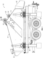
- FIG. 1 is a side elevation view of a dewatering device 10 according to aspects of the invention.
- the dewatering device 10 shown in Figure 1 is a vibrating screen 12 type, which receives an amount of aggregate product and vibrates a screen 16 to remove liquid from said product.
- An example of such a vibrating screen is shown and described in U.S. Patent No. 8,695,804 , which is hereby incorporated by reference in its entirety. It should be appreciated that the dewatering device in the '804 patent is a fixed-in-place dewatering device, which must be fully installed as an integral unit.
- a dewatering device 10 such as that shown in the figures, can be utilized to move said dewatering device 10 relative the exit of the screw dehydrator wherein the aggregate material moved by the screw will be deposited into the dewatering device 10. This will greatly increase the efficiency of the facility, while maintaining a lower cost of including higher efficiency equipment without a full replacement of existing equipment.
- additional supports can be included to maintain the temporary fixed location of the device 10. The device can be used solely with a single conveying means, or else can then be utilized with additional conveyors that are used at the same or different facilities.
- Figures 1-3 disclose the use of a dewatering device 10 with wheels 42 for providing portability thereof, it should be appreciated that other systems and other devices can include additional ways for movement of the dewatering device.
- Figure 4 discloses a dewatering device 10 which includes skids 44, which make the dewatering device 10 a more stationary device. The rest of the components of the dewatering device 10 are similar to that previously disclosed and described. However, instead of moving the device with the wheels 42, the skids 44 allow for the dewatering device to be stationary or fixed at a location for use with an existing conveying means of aggregate product, such as a screw conveyor.
- the return hose or pipe will direct the slurry mixture including any liquid and fine materials back towards the dewatering device 10, such as passing them back on or in the screw conveyor 50, as is shown in Figure 6 .
- the location of the return hose or pipe 38 will put the fine material slurry at such a location where it will be deposited back into the vibrating screen 12 of the dewatering device 10.
- the vibrating of the screen 16 will move the slurry and any additional aggregate product towards the exit 20 for use thereof.
- the recycle system 26 of the dewatering device 10 can be used with an existing conveyor 50 such that a greater amount of aggregate material, including the fine materials, can be captured by the retro-fit dewatering system.
- the dewatering device 10 can be used with existing screw conveyors or other conveyor means such that an entire dewatering system need not be replaced. The portability of the dewatering device 10 of the invention can therefore increase efficiency while keeping installation cost at a minimum.
- the use of the dewatering device can achieve moisture content as low as 8% for a saleable product in less than a day.
- a deeper bed depth allows screens to remove more moisture. Aggressive throw allows for higher feed tonnage and faster drying cycles.
- the urethane screen can include sidewalls for additional dewatering along the sides of the bed.
- the portability of the device will allow for the device to be used with existing facilities without the cost and time of having to replace existing facilities, such as existing screw conveyors that are currently used for the dewatering of aggregate product.
- the portable system can simply be moved to a location of use and positioned adjacent any existing facilities for use almost instantaneously.
- the amount of power consumption will be less than that which is required for other types of dewatering devices. For example, it is contemplated that the horse power required is reduced up to one-third of that currently required by existing dewatering devices.
- a stationary system can be retro-fit to be independent of but used with an existing facility to include the use of the recycling system of the device 10 to increase the amount of aggregate product obtained from the system.
- the dewatering device can be manipulated to be used with a wide range of sizes of conveyor or dewatering means.
- the height of the dewatering device can be varied according to the support members of the dewatering device 10.
- the dewatering device be included with a lift system, such as a hydraulic lift system in order to raise or lower the vibrating screen 12 relative to an existing conveyor means at a location of use.
- the height may not need to be variable, but the length of nozzle 36 and/or the length of hose or pipe used to connect the nozzle to the conveyor means can also be used to adapt the dewatering device for use with different sizes of existing facilities. Still further adjustments may be made to the dewatering device to allow for the near universal use of the dewatering device with any type of existing dewatering conveyor means or dewatering facility.
- the dewatering device 10 of the invention be used with conveyor systems such as existing screw dewatering conveyor means, it is also contemplated that the screen could be used with other types of dewatering means in which fine materials or the overall efficiency of the dewatering systems is not ideal.
- the retrofittability of the invention allows for the manipulation of the device 10 such that it could be adjusted and/or used with many different types of dewatering systems that are currently in use.
- the device 10 of the invention will allow for the increased efficiency, while maintaining low costs and also increasing efficiency of the dewatering process of aggregate product.
Landscapes
- Engineering & Computer Science (AREA)
- Mechanical Engineering (AREA)
- General Engineering & Computer Science (AREA)
- Life Sciences & Earth Sciences (AREA)
- Chemical & Material Sciences (AREA)
- Chemical Kinetics & Catalysis (AREA)
- Health & Medical Sciences (AREA)
- Molecular Biology (AREA)
- Agronomy & Crop Science (AREA)
- Treatment Of Sludge (AREA)
- Treatment Of Liquids With Adsorbents In General (AREA)
Description
- The invention relates generally to dewatering aggregate products, such as sand, gravel, ore, or minerals. More particularly, but not exclusively, the invention relates to a retro-fit device, which can be portable or stationary, for use with existing dewatering devices to increase the dewatering of the product while also minimizing power input. Such a dewatering device is known from the
US2009/057204A . - In the processing and handling of aggregate materials such as sand, gravel or crushed stone, as well as in related industrial materials like coal, slag, iron ore, phosphate, potash, primary metal and related chemical industries, it is necessary to utilize relatively large quantities of water or other liquids in conjunction with or as a dispersing medium for finely sized solid particles produced in the respective grading, concentration or other process. At some point in the process, it is usually necessary to subsequently effect a separation or dewatering of these fine solid materials from the slurry containing them.
- One method of dewatering fine granular material prior to disposing of the waste water or other liquid has been to subject the mixture to suitable dewatering devices. The most widely employed method for dewatering in the mineral aggregates industry is an inclined screw dehydrator, which slowly moves the solid material up the incline of the screw thread out of a feed basin permitting back flow of the water to waste. However, such equipment has limited water handling capacity and is plagued by the loss of valuable fines that are carried away in the back flow.
- Another technique involves the use of centrifugal force to remove the free moisture. However, the high cost, high power consumption, and wear characteristics associated with such a centrifuge apparatus have prevented the wide use of that technique on a commercial basis for handling abrasive materials. Similarly, the use of pressure or vacuum filters has not been commercially attractive, particularly for the sand and gravel and crushed stone industries.
- Another common technique employed for dewatering fine particle slurries is the use of vibrating dewatering screens. The deck of these screens has often taken the form of finely woven wire cloth through which material may pass. Some have in recent times used urethane decks with small openings for water to pass. However the typical horsepower consumption of a dewatering screen system is high. Moisture content may vary by particle size and mineral composition.
- Furthermore, many of these machines used to dewater the aggregate product are expensive and already in place. It is not cost effective to replace entire systems with systems such as those disclosed in
U.S. Patent No. 8,695,804 . - As such, there is a need in the art for a drop in or retro-fit unit that can be used with one or more of the existing machines to provide for a dewatering device and recycle device to dry aggregate product and to recycle fine materials that may pass unwanted through a vibrating screen or other drying member.
- It is therefore a primary object, feature, and/or advantage of the invention to overcome or improve deficiencies in the art.
- It is another object, feature, and/or advantage of the invention to provide a drop in or retro-fit dewatering device capable of being used with existing dewatering systems to retro-fit said systems for greater efficiency in capturing fine materials.
- It is still another object, feature, and/or advantage of the invention to provide a dewatering device that can be moved on skids, wheels, or other members.
- It is yet another object, feature, and/or advantage of the invention to provide a dewatering device that can work with an existing screw conveyor to decrease moisture level of aggregate material with minimum power consumption.
- It is a further object, feature, and/or advantage of the invention to provide a dewatering device with a recycle system to capture a higher amount of dried aggregate product.
- These and/or other objects, features, and advantages of the present invention will be apparent to those skilled in the art.
- According to the invention, a dewatering device is provided disclosing the features of claim 1. The dewatering device can be used with existing drying systems, such as screw conveyor or other conveyors, to retro-fit the system to include components to increase the efficiency of the dewatering systems without greatly increasing power consumption.
- The dewatering system includes a vibrating screen including a housing comprising side walls. The housing receives aggregate product from the conveyor device. The screen is movable or otherwise vibrating, such as in two directions. A vibrating system, such as motors, flywheels, or some combination thereof, provides the movement to the screen. The screen allows water to pass but not product, which, when dried sufficiently, passes out an outlet of the housing. However, some fine materials may pass with the water through the screen.
- A recycle system is positioned at least partially below the screen and includes an underflume for receiving the fine materials and water. The underflume includes an aperture at a lowest point for directing the water and fine materials. The mixture passes through the aperture and into a hose or pipe where water is flowing to direct the mixture through the recycling system and back toward the vibrating screen, such as via the conveyor, where it is re-dried and passed toward the outlet.
- The dewatering system can be movable. Thus, wheels, skids, or other movable members can be connected to supports for the system. The movable members allow the dewatering member to be portable and positioned in place adjacent existing drying systems. Furthermore, the portability of the system allows it to be used with multiple drying systems depending upon their location and need of use.
-
-
Figure 1 is a side elevation view of a dewatering device according to aspects of the invention. -
Figure 2 is a top plan view of the dewatering device. -
Figure 3 is a rear elevation view of the dewatering device. -
Figure 4 is a side elevation view of a dewatering device according to additional aspects of the invention. -
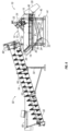
Figure 5 is a perspective schematic of the dewatering device in use with a screw conveyor. -
Figure 6 is a sectional schematic view of the dewatering device in use with the screw conveyor. - Various embodiments of the present invention will be described in detail with reference to the drawings, wherein like reference numerals represent like parts throughout the several views. Reference to various embodiments does not limit the scope of the invention. Figures represented herein are not limitations to the various embodiments according to the invention and are presented for exemplary illustration of the invention.
- The various figures herein disclosed include aspects of a dewatering
device 10 according to aspects of the invention. As will be understood, thedewatering device 10 of the invention provides numerous advantages over the current art. For example, currently, entire systems are used and put in place for dewatering aggregate product, such as sand, ore, gravel, and the like. These systems are expensive, massive, and can take a large amount of time to install. However, as they are beneficial in the dewatering process, they are needed for the dewatering processes. For example, many of the conveyor systems, such as screw conveyors and the like can move large amounts of aggregate product. In many instances, existing dewatering facilities have one or more types of dewatering devices, which have been previously installed and are currently in use. However, some of these existing devices have been in use for many years, and do not include the most up-to-date technology for dewatering. Therefore, thedewatering device 10 of the invention provides for a unique and novel system for retrofitting many of the existing dewatering facilities to increase the efficiency of the dewatering processes at said facilities, while minimizing the cost for the updating and also minimizing the power required to run said facilities once the contents of the invention have been included and retrofit to the existing facilities. -
Figure 1 is a side elevation view of adewatering device 10 according to aspects of the invention. Thedewatering device 10 shown inFigure 1 is a vibratingscreen 12 type, which receives an amount of aggregate product and vibrates ascreen 16 to remove liquid from said product. An example of such a vibrating screen is shown and described inU.S. Patent No. 8,695,804 , which is hereby incorporated by reference in its entirety. It should be appreciated that the dewatering device in the '804 patent is a fixed-in-place dewatering device, which must be fully installed as an integral unit. - Therefore, the
dewatering device 10 as shown inFigure 1 is a vibratingscreen 12. The vibratingscreen 12 includes ahousing 14, which comprises a plurality of walls defining an interior reservoir for receiving an amount of aggregate product from a conveying device, such as a screw conveyor. The vibratingscreen 12 receives the aggregate product at anentrance 18 to which the aggregate product is added to thescreen 16 itself. Thescreen 16 is a vibratory screen in which the screen is movable in at least two directions to vibrate the aggregate product thereon. For example, thescreen 16 may be a urethane deck with one-quarter millimeter apertures to allow the screen to dewater a broad range of particle sizes. The screen may cover a generally planar portion of the reservoir along with extending up at least portions of the walls to increase the amount of area for dewatering the aggregate product. Depending on the application, the openings or apertures in the screen can be up to one millimeter. The deck of the vibratingscreen 12 can handle up to 14 inches of material depth, making use of a bottom layer material as filter media. However, the exact dimensions and capabilities of the screen are not to be limited to those precisely disclosed in the invention, and variations to the same are to be included. Those skilled in the art will recognize that different types of screens will be able to handle different types of materials for dewatering thereof. - As mentioned, the screen is a
vibratory screen 16 which is movable in more than one direction. The movement of thescreen 16 allows for the dewatering of aggregate product applied thereto. A vibratingsystem 22 may be included and operatively connected to the vibratingscreen 16 to provide movement thereof.Figure 1 shows a vibratingsystem 22 comprising a first andsecond motor Springs 46, such as compression springs, are placed around thescreen housing 14 to allow the movement of the vibratingscreen 12 and to provide an opposing force to move the screen back to its original orientation. Therefore, as the motors are causing the movement of the screen, thesprings 46 will work with said motors to provide for the continuous movement of thescreen 16 to dewater the aggregate product applied thereon. - Furthermore, it should be appreciated that other types of vibrating
systems 22 could be utilized to move thescreen 16 and/orscreen housing 14. For example, a flywheel could be operably connected to thehousing 14 in which the rotation of the flywheel is off centered such that it causes movement of thescreen 16 in more than one direction to provide for the dewatering of the aggregate product applied thereon. Still other types of vibratingsystems 22 are contemplated including a combination of flywheel and motor, flywheel, motor, cams, and/or springs, and the like. Furthermore, any combination of said vibrating systems could be utilized to provide the movement of the aggregate product on the spring. - After the aggregate product has been vibrated on the screen, much of the water will be allowed to pass through the screen apertures to an area below said
screen 16. The product is then moved towards anexit 20 of thedewatering device 10, where it can be utilized in a substantially drier form. Theexit 20 may include a chute, or other funnel-type member to direct the dried or substantially dried aggregate product towards the exit of thedewatering device 10. - While the
screen 16 is chosen such that water will pass while mostly aggregate product will not, it is contemplated that fine materials 64 ("fines") may still pass through thescreen 16. This is unwanted, as it is desired to capture as much aggregate product as possible by thedewatering system 10. Therefore, thedewatering device 10 of the invention includes arecycle system 26 to capture any fine materials that may pass through thescreen 16 and which would otherwise be lost. Therecycle system 26 includes anunderflume portion 28, which may also be a trailer or other reservoir type member. As shown in the figures, theunderflume trailer 28 is shaped such that any water and/or fine materials passing therethrough will be directed towards a bottommost location ofunderflume 28 and towards anaperture 30 therethrough. See, e.g., thearrow 64 inFigure 6 . At theaperture 30 of therecycle system 26, ahose connection 34 allows connection of anozzle 36 and awater feed 32. Thewater feed 32 may be any existing water source that is located at the facility or area of use of thedewatering device 10. The water source could also be a portable water source (not shown). - The
nozzle 36 is shaped to increase the velocity of the water and fine material slurry as it passes through thenozzle 36. This increased velocity of the slurry will aid in increasing the efficiency of therecycle system 26 to capture as much of the fine materials that are passed therethrough. For example, the fine materials in water that pass through theunderflume 28 of therecycle system 26 are passed through theaperture 30 therein and into or towards thenozzle 36. The water coming from thewater feed 32 will reach the nozzle and mix with the fine materials passed therethrough to create a slurry. The slurry passes through thenozzle 36 such that the velocity of the fluid is increased as the diameter of the nozzle decreases to aid in moving the slurry mixture in the orientation of the nozzle. The orientation of thenozzle 36 is directed towards a return hose orpipe 38, which will pass the slurry mixture back towards thescreen 16 of thedewatering device 10 such that the fine materials of the slurry mixture will be re-vibrated and dried such that they are passed out theexit 20 of thedewatering device 10. - The
recycling system 26 of the invention provides numerous advantages in that it allows the capture of any fine materials that may pass through the apertures of thescreen 16, and which would previously have been lost or not utilized by the dewatering device. The continuously looped system of the recycle system with the dewatering capabilities of thedewatering device 10 allows for a greater efficiency in capturing the amount of dried aggregate product by thedewatering device 10. - Furthermore, it should be appreciated that the
dewatering device 10 is housed on asupport 40 when used with a conveyor system of a facility. Thesupport 40, as shown inFigures 1-3 , may include a plurality ofwheels 42 including axles connected to the wheels. Thewheels 42 of thedewatering device 10 allow for the movement of the dewatering device relative to a fixed conveying system of an existing dry or dewatering system for aggregate product. Therefore, thewheels 42 allow for the portability of thedewatering device 10 such that it can be used with one or more existing conveying systems of aggregate product, which provides for the advantages of not requiring a complete install of a system, such as that disclosed in the '804 patent, which can include a higher cost. - For example, many aggregate dewatering facilities include the use of a screw conveyor for dewatering the aggregate product. However, these facilities may want to include the use of a dewatering device, such as that with a dewatering or vibrating screen and a recycle system in order to increase the efficiency and amount of aggregate product dried or dewatered and captured using the system. As previously disclosed, using only incline screw dehydrators has limited watering handling capacity and is plagued by the loss of valuable fines that are carried away in the backflow. Therefore, the use of a dewatering system, such as that disclosed in the
dewatering device 10 of the invention can be utilized. However, instead of having to replace the entire screw dehydrator, adewatering device 10, such as that shown in the figures, can be utilized to move saiddewatering device 10 relative the exit of the screw dehydrator wherein the aggregate material moved by the screw will be deposited into thedewatering device 10. This will greatly increase the efficiency of the facility, while maintaining a lower cost of including higher efficiency equipment without a full replacement of existing equipment. Once thedewatering device 10 is positioned adjacent the screw dehydrator, additional supports can be included to maintain the temporary fixed location of thedevice 10. The device can be used solely with a single conveying means, or else can then be utilized with additional conveyors that are used at the same or different facilities. However, it should be appreciated that, while thedevice 10 may be portable, it may also be fixed in place or stationary, but still able to be used to retro-fit an existing facility, such as a facility with a conveyor, in order to provide a dewatering system that incorporates the recycling system of thedevice 10 to increase the efficiency of the system. - While
Figures 1-3 disclose the use of adewatering device 10 withwheels 42 for providing portability thereof, it should be appreciated that other systems and other devices can include additional ways for movement of the dewatering device. For example,Figure 4 discloses adewatering device 10 which includesskids 44, which make the dewatering device 10 a more stationary device. The rest of the components of thedewatering device 10 are similar to that previously disclosed and described. However, instead of moving the device with thewheels 42, theskids 44 allow for the dewatering device to be stationary or fixed at a location for use with an existing conveying means of aggregate product, such as a screw conveyor. - Still other types of support apparatus are intended to be included, which can allow the device to be portable or stationary, including the combination wheels and skids, skis, tracks, and the like. In addition, the use of a hitch can be included to attach the
dewatering device 10 to a vehicle in order to more easily move the device relative to one or more of the existing dewatering systems. - Furthermore, it is to be appreciated that the wheels or other movement apparatuses can be removed from the
dewatering device 10 once thedevice 10 is in a location of use. Therefore, the device can be portable when needed, but can be more fixed in place or stationary when used with a conveying means, such as a screw conveyor of the type for use in moving aggregate product. -
Figures 5 and6 disclose the positioning and use of thedewatering device 10 with aconveyor 50 of aggregate product, which is shown to be ascrew conveyor 52 of the type known and used. As shown in the figures, theconveyor 50 includes ahousing 54 which includes anentrance 60 for receivingaggregate product 56. Theaggregate product 56, which includes a water slurry, is added into theentrance 60 at the first end of thescrew conveyor 52. Thescrew 52, which includes a plurality offlights 66, is powered byscrew motor 68, which is shown to be at the exit end 62 of theconveyor 50. However, the exact configuration of theconveyor 50 is not to be limited to the invention, and generally any types of conveyors can be used with thedewatering device 10 of the invention. - The
aggregate product 56 included in theconveyor housing 54 is moved via theflights 66 of thescrew 52 towards theexit 62 thereof. Thescrew conveyor 50 will remove some of the water from the slurry product. At theexit 62 of theconveyor 50, the remaining slurry is deposited on to thescreen 16 of thedewatering device 10 at theentrance 18 thereof. At this location, the motors or vibratingsystem 22 of thedewatering device 10 will cause movement of thescreen 16. The movement of thescreen 16 in multiple directions will allow water or other liquids to pass through the screen, while moving the at least partially dewatered aggregate product towards theexit 20 of thedewatering device 10. - However,
fine materials 64 may still pass through thescreen 16. Thesefine materials 64 can be captured by therecycling system 26 of thedewatering device 10, such as at theunderflume trailer 28 thereof. The shape of the underflume trailer, as shown by thearrow 64 inFigure 6 , will cause the fine materials and any water passing therethrough to be directed towards anaperture 30 in theunderflume trailer 28. The slurry mixture will pass through the aperture and will be mixed with water from awater feed 32 at ahose connection 34, where it is directed into anozzle 36 of thedewatering device 10. Thenozzle 36 can increase the velocity of the liquid slurry and pass the liquid slurry into a return hose orpipe 38. The return hose or pipe will direct the slurry mixture including any liquid and fine materials back towards the dewateringdevice 10, such as passing them back on or in thescrew conveyor 50, as is shown inFigure 6 . The location of the return hose orpipe 38 will put the fine material slurry at such a location where it will be deposited back into the vibratingscreen 12 of thedewatering device 10. The vibrating of thescreen 16 will move the slurry and any additional aggregate product towards theexit 20 for use thereof. - Therefore, the
recycle system 26 of thedewatering device 10 can be used with an existingconveyor 50 such that a greater amount of aggregate material, including the fine materials, can be captured by the retro-fit dewatering system. In addition, as thedewatering device 10 is portable, it can be used with existing screw conveyors or other conveyor means such that an entire dewatering system need not be replaced. The portability of thedewatering device 10 of the invention can therefore increase efficiency while keeping installation cost at a minimum. - Those skilled in the art will recognize numerous advantages of the
dewatering device 10 of the invention. The use of the dewatering device can achieve moisture content as low as 8% for a saleable product in less than a day. A deeper bed depth allows screens to remove more moisture. Aggressive throw allows for higher feed tonnage and faster drying cycles. In addition, the urethane screen can include sidewalls for additional dewatering along the sides of the bed. - As has been mentioned, the portability of the device will allow for the device to be used with existing facilities without the cost and time of having to replace existing facilities, such as existing screw conveyors that are currently used for the dewatering of aggregate product. The portable system can simply be moved to a location of use and positioned adjacent any existing facilities for use almost instantaneously. In addition, the amount of power consumption will be less than that which is required for other types of dewatering devices. For example, it is contemplated that the horse power required is reduced up to one-third of that currently required by existing dewatering devices.
- However, the use of the device, even when not portable, such as the
stationary device 10 shown inFigure 4 , will allow for the benefits of the recycle system to be retro-fit or otherwise added to existing facilities. For example, a stationary system can be retro-fit to be independent of but used with an existing facility to include the use of the recycling system of thedevice 10 to increase the amount of aggregate product obtained from the system. - It should also be appreciated that the dewatering device can be manipulated to be used with a wide range of sizes of conveyor or dewatering means. For example, the height of the dewatering device can be varied according to the support members of the
dewatering device 10. For example, it is contemplated that the dewatering device be included with a lift system, such as a hydraulic lift system in order to raise or lower the vibratingscreen 12 relative to an existing conveyor means at a location of use. Furthermore, the height may not need to be variable, but the length ofnozzle 36 and/or the length of hose or pipe used to connect the nozzle to the conveyor means can also be used to adapt the dewatering device for use with different sizes of existing facilities. Still further adjustments may be made to the dewatering device to allow for the near universal use of the dewatering device with any type of existing dewatering conveyor means or dewatering facility. - For example, while it is contemplated that the
dewatering device 10 of the invention be used with conveyor systems such as existing screw dewatering conveyor means, it is also contemplated that the screen could be used with other types of dewatering means in which fine materials or the overall efficiency of the dewatering systems is not ideal. The retrofittability of the invention allows for the manipulation of thedevice 10 such that it could be adjusted and/or used with many different types of dewatering systems that are currently in use. Thedevice 10 of the invention will allow for the increased efficiency, while maintaining low costs and also increasing efficiency of the dewatering process of aggregate product. - Still other advantages obvious to those skilled in the art will be appreciated and included as part of the invention.
Claims (14)
- A dewatering device (10) for aggregate product for use with an existing drying system for dewatering aggregate product, said existing drying system comprising a conveyor to move the aggregate product, and said dewatering device comprising:a vibrating screen (12) for receiving aggregate product from the existing drying system conveyor, said vibrating screen including a vibrating system (22) to move said screen;a recycle system positioned at least partially below the vibrating screen to receive fine materials passed through the screen;and characterized in that said recycle system (26) includes an underflume with an aperture and a return hose (38) operatively connected to the underflume to direct the fine materials through the recycling system and back towards the vibrating screen; andsaid dewatering device (10) being independent of the existing drying system in a manner that the dewatering device can be portable in relation to the existing drying system.
- The dewatering device of claim 1, further comprising skids (44) at least partially supporting the dewatering device.
- The dewatering device of claim 1, further comprising wheels (42) at least partially supporting the dewatering device.
- The dewatering device of claim 1, wherein said vibrating screen includes an entrance (18) for receiving aggregate product and an exit for passing dewatered aggregate product.
- The dewatering device of claim 1, wherein the vibrating system comprises one or more vibrating motors to linearly and horizontally move said vibrating screen.
- The dewatering device of claim 1, wherein the vibrating system comprises a flywheel operatively connected to the vibrating screen to move said screen.
- The dewatering device of claim 1, wherein the existing system comprises an inclined screw.
- The dewatering device of claim 1, wherein the hose (38) is a water hose for passing water and fine material toward the vibrating screen.
- The dewatering device of claim 1, wherein said recycle system comprises an underflume trailer (28) for receiving the fine material.
- The dewatering device of claim 9, wherein said recycle system further comprises a water hose (38) operatively connected to the underflume trailer (28) to redirect the fine material toward the vibrating screen (12).
- The dewatering device of claim 1 wherein the vibrating screen (12) is positioned at least partially below the conveyor to receive aggregate product therefrom and movable by a vibrating system to dry the product;
- The dewatering device of claim 11, wherein the vibrating screen (12) comprises a housing (14) with an entrance for receiving aggregate product from the conveyor, an outlet for directing dried product, and a screen therebetween that is movable to drain water from the aggregate product.
- The dewatering device of claim 1, further comprising a nozzle (36), wherein said nozzle increases the velocity of the water and fine materials, wherein said nozzle passes said water and fine materials into the return hose (38), wherein said return hose passes said water and fine materials back towards the vibrating screen.
- The dewatering device of claim 1, wherein said recycle system (26) directs the fine materials back toward the vibrating screen (12) via said conveyor.
Applications Claiming Priority (1)
| Application Number | Priority Date | Filing Date | Title |
|---|---|---|---|
| US14/632,747 US9651307B2 (en) | 2015-02-26 | 2015-02-26 | System, methods, and apparatus for aggregate dewatering |
Publications (2)
| Publication Number | Publication Date |
|---|---|
| EP3061511A1 EP3061511A1 (en) | 2016-08-31 |
| EP3061511B1 true EP3061511B1 (en) | 2024-07-10 |
Family
ID=55806262
Family Applications (1)
| Application Number | Title | Priority Date | Filing Date |
|---|---|---|---|
| EP16275036.8A Active EP3061511B1 (en) | 2015-02-26 | 2016-02-24 | Aggre-dry retro-fit system |
Country Status (4)
| Country | Link |
|---|---|
| US (4) | US9651307B2 (en) |
| EP (1) | EP3061511B1 (en) |
| CA (2) | CA2999455C (en) |
| MX (1) | MX2016002264A (en) |
Families Citing this family (14)
| Publication number | Priority date | Publication date | Assignee | Title |
|---|---|---|---|---|
| CN107253599B (en) * | 2017-04-20 | 2019-11-12 | 芜湖市佰昌精密模具有限公司 | A kind of multisection type oil plant particle feed device |
| CN107478040A (en) * | 2017-08-09 | 2017-12-15 | 徐州蕴康农业科技有限公司 | A kind of drying unit for corn processing |
| CN107649357A (en) * | 2017-11-01 | 2018-02-02 | 无锡宇能选煤机械厂 | Carry the spiral screen of buffer-type feeding channel |
| CN107952671A (en) * | 2017-12-16 | 2018-04-24 | 洛阳隆中重工机械有限公司 | Dry tailings drainage device |
| CN108393271B (en) * | 2018-02-10 | 2020-07-07 | 泉州台商投资区忆品茶业有限公司 | A seed dust removal and drying device |
| FI127919B (en) | 2018-05-08 | 2019-05-15 | Metso Minerals Inc | Moving viewing frame and movable plant for processing mineral materials |
| WO2020047131A1 (en) * | 2018-08-28 | 2020-03-05 | Superior Industries, Inc. | Aggregate processing systems, methods and apparatus |
| CN110065822A (en) * | 2019-05-05 | 2019-07-30 | 樊祥 | Energy-saving building materials production bulking machine with charging dust collection mechanism |
| US11479492B2 (en) | 2020-03-18 | 2022-10-25 | Afco 360, Llc | Fast flow dewatering trailer apparatus and method of use |
| US11890782B2 (en) | 2020-06-05 | 2024-02-06 | Vermeer Manufacturing Company | Mixing systems having disk assemblies |
| CN111822318B (en) * | 2020-07-06 | 2021-11-16 | 宿迁市高速铁路建设发展有限公司 | A kind of sand and gravel screening machine for traffic construction and using method |
| CN112141559A (en) * | 2020-09-07 | 2020-12-29 | 武汉雅洁净环境工程有限公司 | Movable automatic garbage collection system |
| CN112657841A (en) * | 2020-12-24 | 2021-04-16 | 安徽理工大学 | Dry screening plant of cat grain granule |
| CN114877669B (en) * | 2022-05-09 | 2023-07-25 | 常州市佳发制粒干燥设备有限公司 | Material conveying device of boiling granulating dryer |
Family Cites Families (7)
| Publication number | Priority date | Publication date | Assignee | Title |
|---|---|---|---|---|
| FR1454244A (en) | 1965-11-16 | 1966-07-22 | Beteiligungs & Patentverw Gmbh | Underwater screening device |
| EP0072590B1 (en) | 1981-08-15 | 1986-12-10 | Derek Parnaby Cyclones International Limited | Vibrating dewatering screen for an apparatus for recovery of particulate matter from suspension |
| US5552044A (en) * | 1991-07-15 | 1996-09-03 | Abel; Gunther | Apparatus for separating solid material and liquid |
| US7785866B2 (en) * | 2006-04-11 | 2010-08-31 | Nathan Ernest Winslow | Compost tea apparatus |
| US8695804B2 (en) | 2007-09-04 | 2014-04-15 | Greystone, Inc. | Sand dewatering device and method |
| CA2689719C (en) * | 2009-01-07 | 2013-03-19 | M-I L.L.C. | Sand screw dryer |
| US8287419B2 (en) * | 2010-05-04 | 2012-10-16 | Kem-Tron Technologies, Inc. | Asymmetric planetary drive assembly for use in shakers |
-
2015
- 2015-02-26 US US14/632,747 patent/US9651307B2/en active Active
-
2016
- 2016-02-18 CA CA2999455A patent/CA2999455C/en active Active
- 2016-02-18 CA CA2921329A patent/CA2921329C/en active Active
- 2016-02-19 MX MX2016002264A patent/MX2016002264A/en active IP Right Grant
- 2016-02-24 EP EP16275036.8A patent/EP3061511B1/en active Active
- 2016-06-22 US US15/189,605 patent/US10393435B2/en active Active
-
2019
- 2019-08-26 US US16/550,539 patent/US10907898B2/en active Active
-
2021
- 2021-02-01 US US17/248,647 patent/US11466933B2/en active Active
Also Published As
| Publication number | Publication date |
|---|---|
| CA2999455C (en) | 2020-05-12 |
| US10393435B2 (en) | 2019-08-27 |
| US9651307B2 (en) | 2017-05-16 |
| CA2921329A1 (en) | 2016-08-26 |
| CA2999455A1 (en) | 2016-08-26 |
| US20210156614A1 (en) | 2021-05-27 |
| US11466933B2 (en) | 2022-10-11 |
| US20160252303A1 (en) | 2016-09-01 |
| US20160298904A1 (en) | 2016-10-13 |
| US10907898B2 (en) | 2021-02-02 |
| EP3061511A1 (en) | 2016-08-31 |
| US20190376743A1 (en) | 2019-12-12 |
| MX2016002264A (en) | 2016-11-24 |
| CA2921329C (en) | 2018-05-15 |
Similar Documents
| Publication | Publication Date | Title |
|---|---|---|
| US11466933B2 (en) | Aggregate dewatering device and method | |
| EP2188116B1 (en) | Sand dewatering device and method | |
| EP3554667B1 (en) | Method and apparatus for washing and grading sand | |
| EP3405295B1 (en) | Method and apparatus for washing and grading silica sand for glass production | |
| JP7316296B2 (en) | Equipment for grading and washing sand | |
| GB2559360B (en) | Apparatus for washing and grading aggregate | |
| US11215397B2 (en) | Vibration unit assembly for a belt conveyor | |
| US2813630A (en) | Material trap | |
| CA3098660C (en) | Method and apparatus for washing and grading sand | |
| CA3068407C (en) | Vibration unit assembly for a belt conveyor | |
| RU2110337C1 (en) | Bulk material separating apparatus |
Legal Events
| Date | Code | Title | Description |
|---|---|---|---|
| PUAI | Public reference made under article 153(3) epc to a published international application that has entered the european phase |
Free format text: ORIGINAL CODE: 0009012 |
|
| 17P | Request for examination filed |
Effective date: 20160307 |
|
| AK | Designated contracting states |
Kind code of ref document: A1 Designated state(s): AL AT BE BG CH CY CZ DE DK EE ES FI FR GB GR HR HU IE IS IT LI LT LU LV MC MK MT NL NO PL PT RO RS SE SI SK SM TR |
|
| AX | Request for extension of the european patent |
Extension state: BA ME |
|
| STAA | Information on the status of an ep patent application or granted ep patent |
Free format text: STATUS: REQUEST FOR EXAMINATION WAS MADE |
|
| R17P | Request for examination filed (corrected) |
Effective date: 20160307 |
|
| STAA | Information on the status of an ep patent application or granted ep patent |
Free format text: STATUS: EXAMINATION IS IN PROGRESS |
|
| 17Q | First examination report despatched |
Effective date: 20220215 |
|
| GRAP | Despatch of communication of intention to grant a patent |
Free format text: ORIGINAL CODE: EPIDOSNIGR1 |
|
| STAA | Information on the status of an ep patent application or granted ep patent |
Free format text: STATUS: GRANT OF PATENT IS INTENDED |
|
| INTG | Intention to grant announced |
Effective date: 20230419 |
|
| GRAJ | Information related to disapproval of communication of intention to grant by the applicant or resumption of examination proceedings by the epo deleted |
Free format text: ORIGINAL CODE: EPIDOSDIGR1 |
|
| STAA | Information on the status of an ep patent application or granted ep patent |
Free format text: STATUS: EXAMINATION IS IN PROGRESS |
|
| INTC | Intention to grant announced (deleted) | ||
| GRAP | Despatch of communication of intention to grant a patent |
Free format text: ORIGINAL CODE: EPIDOSNIGR1 |
|
| STAA | Information on the status of an ep patent application or granted ep patent |
Free format text: STATUS: GRANT OF PATENT IS INTENDED |
|
| INTG | Intention to grant announced |
Effective date: 20240404 |
|
| GRAS | Grant fee paid |
Free format text: ORIGINAL CODE: EPIDOSNIGR3 |
|
| GRAA | (expected) grant |
Free format text: ORIGINAL CODE: 0009210 |
|
| STAA | Information on the status of an ep patent application or granted ep patent |
Free format text: STATUS: THE PATENT HAS BEEN GRANTED |
|
| AK | Designated contracting states |
Kind code of ref document: B1 Designated state(s): AL AT BE BG CH CY CZ DE DK EE ES FI FR GB GR HR HU IE IS IT LI LT LU LV MC MK MT NL NO PL PT RO RS SE SI SK SM TR |
|
| REG | Reference to a national code |
Ref country code: CH Ref legal event code: EP |
|
| REG | Reference to a national code |
Ref country code: DE Ref legal event code: R096 Ref document number: 602016088320 Country of ref document: DE |
|
| REG | Reference to a national code |
Ref country code: LT Ref legal event code: MG9D |
|
| REG | Reference to a national code |
Ref country code: NL Ref legal event code: MP Effective date: 20240710 |
|
| PG25 | Lapsed in a contracting state [announced via postgrant information from national office to epo] |
Ref country code: PT Free format text: LAPSE BECAUSE OF FAILURE TO SUBMIT A TRANSLATION OF THE DESCRIPTION OR TO PAY THE FEE WITHIN THE PRESCRIBED TIME-LIMIT Effective date: 20241111 |
|
| REG | Reference to a national code |
Ref country code: AT Ref legal event code: MK05 Ref document number: 1701563 Country of ref document: AT Kind code of ref document: T Effective date: 20240710 |
|
| PG25 | Lapsed in a contracting state [announced via postgrant information from national office to epo] |
Ref country code: NL Free format text: LAPSE BECAUSE OF FAILURE TO SUBMIT A TRANSLATION OF THE DESCRIPTION OR TO PAY THE FEE WITHIN THE PRESCRIBED TIME-LIMIT Effective date: 20240710 |
|
| PG25 | Lapsed in a contracting state [announced via postgrant information from national office to epo] |
Ref country code: PT Free format text: LAPSE BECAUSE OF FAILURE TO SUBMIT A TRANSLATION OF THE DESCRIPTION OR TO PAY THE FEE WITHIN THE PRESCRIBED TIME-LIMIT Effective date: 20241111 Ref country code: NL Free format text: LAPSE BECAUSE OF FAILURE TO SUBMIT A TRANSLATION OF THE DESCRIPTION OR TO PAY THE FEE WITHIN THE PRESCRIBED TIME-LIMIT Effective date: 20240710 |
|
| PG25 | Lapsed in a contracting state [announced via postgrant information from national office to epo] |
Ref country code: NO Free format text: LAPSE BECAUSE OF FAILURE TO SUBMIT A TRANSLATION OF THE DESCRIPTION OR TO PAY THE FEE WITHIN THE PRESCRIBED TIME-LIMIT Effective date: 20241010 |
|
| PG25 | Lapsed in a contracting state [announced via postgrant information from national office to epo] |
Ref country code: FI Free format text: LAPSE BECAUSE OF FAILURE TO SUBMIT A TRANSLATION OF THE DESCRIPTION OR TO PAY THE FEE WITHIN THE PRESCRIBED TIME-LIMIT Effective date: 20240710 Ref country code: GR Free format text: LAPSE BECAUSE OF FAILURE TO SUBMIT A TRANSLATION OF THE DESCRIPTION OR TO PAY THE FEE WITHIN THE PRESCRIBED TIME-LIMIT Effective date: 20241011 Ref country code: PL Free format text: LAPSE BECAUSE OF FAILURE TO SUBMIT A TRANSLATION OF THE DESCRIPTION OR TO PAY THE FEE WITHIN THE PRESCRIBED TIME-LIMIT Effective date: 20240710 |
|
| PG25 | Lapsed in a contracting state [announced via postgrant information from national office to epo] |
Ref country code: BG Free format text: LAPSE BECAUSE OF FAILURE TO SUBMIT A TRANSLATION OF THE DESCRIPTION OR TO PAY THE FEE WITHIN THE PRESCRIBED TIME-LIMIT Effective date: 20240710 |
|
| PG25 | Lapsed in a contracting state [announced via postgrant information from national office to epo] |
Ref country code: LV Free format text: LAPSE BECAUSE OF FAILURE TO SUBMIT A TRANSLATION OF THE DESCRIPTION OR TO PAY THE FEE WITHIN THE PRESCRIBED TIME-LIMIT Effective date: 20240710 |
|
| PG25 | Lapsed in a contracting state [announced via postgrant information from national office to epo] |
Ref country code: IS Free format text: LAPSE BECAUSE OF FAILURE TO SUBMIT A TRANSLATION OF THE DESCRIPTION OR TO PAY THE FEE WITHIN THE PRESCRIBED TIME-LIMIT Effective date: 20241110 Ref country code: AT Free format text: LAPSE BECAUSE OF FAILURE TO SUBMIT A TRANSLATION OF THE DESCRIPTION OR TO PAY THE FEE WITHIN THE PRESCRIBED TIME-LIMIT Effective date: 20240710 |
|
| PG25 | Lapsed in a contracting state [announced via postgrant information from national office to epo] |
Ref country code: HR Free format text: LAPSE BECAUSE OF FAILURE TO SUBMIT A TRANSLATION OF THE DESCRIPTION OR TO PAY THE FEE WITHIN THE PRESCRIBED TIME-LIMIT Effective date: 20240710 |
|
| PG25 | Lapsed in a contracting state [announced via postgrant information from national office to epo] |
Ref country code: ES Free format text: LAPSE BECAUSE OF FAILURE TO SUBMIT A TRANSLATION OF THE DESCRIPTION OR TO PAY THE FEE WITHIN THE PRESCRIBED TIME-LIMIT Effective date: 20240710 Ref country code: RS Free format text: LAPSE BECAUSE OF FAILURE TO SUBMIT A TRANSLATION OF THE DESCRIPTION OR TO PAY THE FEE WITHIN THE PRESCRIBED TIME-LIMIT Effective date: 20241010 |
|
| PG25 | Lapsed in a contracting state [announced via postgrant information from national office to epo] |
Ref country code: RS Free format text: LAPSE BECAUSE OF FAILURE TO SUBMIT A TRANSLATION OF THE DESCRIPTION OR TO PAY THE FEE WITHIN THE PRESCRIBED TIME-LIMIT Effective date: 20241010 Ref country code: PL Free format text: LAPSE BECAUSE OF FAILURE TO SUBMIT A TRANSLATION OF THE DESCRIPTION OR TO PAY THE FEE WITHIN THE PRESCRIBED TIME-LIMIT Effective date: 20240710 Ref country code: NO Free format text: LAPSE BECAUSE OF FAILURE TO SUBMIT A TRANSLATION OF THE DESCRIPTION OR TO PAY THE FEE WITHIN THE PRESCRIBED TIME-LIMIT Effective date: 20241010 Ref country code: LV Free format text: LAPSE BECAUSE OF FAILURE TO SUBMIT A TRANSLATION OF THE DESCRIPTION OR TO PAY THE FEE WITHIN THE PRESCRIBED TIME-LIMIT Effective date: 20240710 Ref country code: IS Free format text: LAPSE BECAUSE OF FAILURE TO SUBMIT A TRANSLATION OF THE DESCRIPTION OR TO PAY THE FEE WITHIN THE PRESCRIBED TIME-LIMIT Effective date: 20241110 Ref country code: HR Free format text: LAPSE BECAUSE OF FAILURE TO SUBMIT A TRANSLATION OF THE DESCRIPTION OR TO PAY THE FEE WITHIN THE PRESCRIBED TIME-LIMIT Effective date: 20240710 Ref country code: GR Free format text: LAPSE BECAUSE OF FAILURE TO SUBMIT A TRANSLATION OF THE DESCRIPTION OR TO PAY THE FEE WITHIN THE PRESCRIBED TIME-LIMIT Effective date: 20241011 Ref country code: FI Free format text: LAPSE BECAUSE OF FAILURE TO SUBMIT A TRANSLATION OF THE DESCRIPTION OR TO PAY THE FEE WITHIN THE PRESCRIBED TIME-LIMIT Effective date: 20240710 Ref country code: ES Free format text: LAPSE BECAUSE OF FAILURE TO SUBMIT A TRANSLATION OF THE DESCRIPTION OR TO PAY THE FEE WITHIN THE PRESCRIBED TIME-LIMIT Effective date: 20240710 Ref country code: BG Free format text: LAPSE BECAUSE OF FAILURE TO SUBMIT A TRANSLATION OF THE DESCRIPTION OR TO PAY THE FEE WITHIN THE PRESCRIBED TIME-LIMIT Effective date: 20240710 Ref country code: AT Free format text: LAPSE BECAUSE OF FAILURE TO SUBMIT A TRANSLATION OF THE DESCRIPTION OR TO PAY THE FEE WITHIN THE PRESCRIBED TIME-LIMIT Effective date: 20240710 |
|
| REG | Reference to a national code |
Ref country code: DE Ref legal event code: R097 Ref document number: 602016088320 Country of ref document: DE |
|
| PG25 | Lapsed in a contracting state [announced via postgrant information from national office to epo] |
Ref country code: RO Free format text: LAPSE BECAUSE OF FAILURE TO SUBMIT A TRANSLATION OF THE DESCRIPTION OR TO PAY THE FEE WITHIN THE PRESCRIBED TIME-LIMIT Effective date: 20240710 Ref country code: DK Free format text: LAPSE BECAUSE OF FAILURE TO SUBMIT A TRANSLATION OF THE DESCRIPTION OR TO PAY THE FEE WITHIN THE PRESCRIBED TIME-LIMIT Effective date: 20240710 Ref country code: SM Free format text: LAPSE BECAUSE OF FAILURE TO SUBMIT A TRANSLATION OF THE DESCRIPTION OR TO PAY THE FEE WITHIN THE PRESCRIBED TIME-LIMIT Effective date: 20240710 |
|
| PG25 | Lapsed in a contracting state [announced via postgrant information from national office to epo] |
Ref country code: EE Free format text: LAPSE BECAUSE OF FAILURE TO SUBMIT A TRANSLATION OF THE DESCRIPTION OR TO PAY THE FEE WITHIN THE PRESCRIBED TIME-LIMIT Effective date: 20240710 |
|
| PG25 | Lapsed in a contracting state [announced via postgrant information from national office to epo] |
Ref country code: CZ Free format text: LAPSE BECAUSE OF FAILURE TO SUBMIT A TRANSLATION OF THE DESCRIPTION OR TO PAY THE FEE WITHIN THE PRESCRIBED TIME-LIMIT Effective date: 20240710 |
|
| PG25 | Lapsed in a contracting state [announced via postgrant information from national office to epo] |
Ref country code: SK Free format text: LAPSE BECAUSE OF FAILURE TO SUBMIT A TRANSLATION OF THE DESCRIPTION OR TO PAY THE FEE WITHIN THE PRESCRIBED TIME-LIMIT Effective date: 20240710 Ref country code: IT Free format text: LAPSE BECAUSE OF FAILURE TO SUBMIT A TRANSLATION OF THE DESCRIPTION OR TO PAY THE FEE WITHIN THE PRESCRIBED TIME-LIMIT Effective date: 20240710 |
|
| PLBE | No opposition filed within time limit |
Free format text: ORIGINAL CODE: 0009261 |
|
| STAA | Information on the status of an ep patent application or granted ep patent |
Free format text: STATUS: NO OPPOSITION FILED WITHIN TIME LIMIT |
|
| 26N | No opposition filed |
Effective date: 20250411 |
|
| REG | Reference to a national code |
Ref country code: DE Ref legal event code: R119 Ref document number: 602016088320 Country of ref document: DE |
|
| PG25 | Lapsed in a contracting state [announced via postgrant information from national office to epo] |
Ref country code: SE Free format text: LAPSE BECAUSE OF FAILURE TO SUBMIT A TRANSLATION OF THE DESCRIPTION OR TO PAY THE FEE WITHIN THE PRESCRIBED TIME-LIMIT Effective date: 20240710 |
|
| PG25 | Lapsed in a contracting state [announced via postgrant information from national office to epo] |
Ref country code: MC Free format text: LAPSE BECAUSE OF FAILURE TO SUBMIT A TRANSLATION OF THE DESCRIPTION OR TO PAY THE FEE WITHIN THE PRESCRIBED TIME-LIMIT Effective date: 20240710 |
|
| REG | Reference to a national code |
Ref country code: CH Ref legal event code: PL |
|
| PG25 | Lapsed in a contracting state [announced via postgrant information from national office to epo] |
Ref country code: LU Free format text: LAPSE BECAUSE OF NON-PAYMENT OF DUE FEES Effective date: 20250224 |
|
| PG25 | Lapsed in a contracting state [announced via postgrant information from national office to epo] |
Ref country code: CH Free format text: LAPSE BECAUSE OF NON-PAYMENT OF DUE FEES Effective date: 20250228 |
|
| REG | Reference to a national code |
Ref country code: BE Ref legal event code: MM Effective date: 20250228 |
|
| PG25 | Lapsed in a contracting state [announced via postgrant information from national office to epo] |
Ref country code: DE Free format text: LAPSE BECAUSE OF NON-PAYMENT OF DUE FEES Effective date: 20250902 |
|
| PG25 | Lapsed in a contracting state [announced via postgrant information from national office to epo] |
Ref country code: FR Free format text: LAPSE BECAUSE OF NON-PAYMENT OF DUE FEES Effective date: 20250228 |
|
| PG25 | Lapsed in a contracting state [announced via postgrant information from national office to epo] |
Ref country code: BE Free format text: LAPSE BECAUSE OF NON-PAYMENT OF DUE FEES Effective date: 20250228 |
|
| PG25 | Lapsed in a contracting state [announced via postgrant information from national office to epo] |
Ref country code: IE Free format text: LAPSE BECAUSE OF NON-PAYMENT OF DUE FEES Effective date: 20250224 |
|
| PGFP | Annual fee paid to national office [announced via postgrant information from national office to epo] |
Ref country code: GB Payment date: 20260121 Year of fee payment: 11 |