EP3061489A2 - Konnektor für einen dialysator - Google Patents
Konnektor für einen dialysator Download PDFInfo
- Publication number
- EP3061489A2 EP3061489A2 EP16155908.3A EP16155908A EP3061489A2 EP 3061489 A2 EP3061489 A2 EP 3061489A2 EP 16155908 A EP16155908 A EP 16155908A EP 3061489 A2 EP3061489 A2 EP 3061489A2
- Authority
- EP
- European Patent Office
- Prior art keywords
- connector
- dialyzer
- line
- connection
- blood
- Prior art date
- Legal status (The legal status is an assumption and is not a legal conclusion. Google has not performed a legal analysis and makes no representation as to the accuracy of the status listed.)
- Granted
Links
- 238000000502 dialysis Methods 0.000 title claims description 16
- 230000008878 coupling Effects 0.000 claims abstract description 47
- 238000010168 coupling process Methods 0.000 claims abstract description 47
- 238000005859 coupling reaction Methods 0.000 claims abstract description 47
- 239000012530 fluid Substances 0.000 claims abstract description 24
- 238000004891 communication Methods 0.000 claims abstract description 3
- 239000008280 blood Substances 0.000 claims description 55
- 210000004369 blood Anatomy 0.000 claims description 55
- 239000007788 liquid Substances 0.000 claims description 37
- 239000000385 dialysis solution Substances 0.000 claims description 24
- 239000012528 membrane Substances 0.000 claims description 13
- 238000000034 method Methods 0.000 claims description 10
- 230000036770 blood supply Effects 0.000 claims description 8
- 230000000903 blocking effect Effects 0.000 claims description 6
- 230000002209 hydrophobic effect Effects 0.000 claims description 6
- 230000002457 bidirectional effect Effects 0.000 claims description 3
- 210000004379 membrane Anatomy 0.000 description 13
- 230000001419 dependent effect Effects 0.000 description 6
- FAPWRFPIFSIZLT-UHFFFAOYSA-M Sodium chloride Chemical compound [Na+].[Cl-] FAPWRFPIFSIZLT-UHFFFAOYSA-M 0.000 description 5
- 230000008901 benefit Effects 0.000 description 5
- 238000011109 contamination Methods 0.000 description 5
- 239000012487 rinsing solution Substances 0.000 description 5
- 239000000243 solution Substances 0.000 description 5
- 238000011010 flushing procedure Methods 0.000 description 4
- 230000004888 barrier function Effects 0.000 description 3
- 230000002572 peristaltic effect Effects 0.000 description 3
- 230000008569 process Effects 0.000 description 3
- 230000001954 sterilising effect Effects 0.000 description 3
- 238000004659 sterilization and disinfection Methods 0.000 description 3
- 230000017531 blood circulation Effects 0.000 description 2
- 239000000356 contaminant Substances 0.000 description 2
- 238000002615 hemofiltration Methods 0.000 description 2
- 230000037452 priming Effects 0.000 description 2
- 238000005086 pumping Methods 0.000 description 2
- 238000000108 ultra-filtration Methods 0.000 description 2
- HTTJABKRGRZYRN-UHFFFAOYSA-N Heparin Chemical compound OC1C(NC(=O)C)C(O)OC(COS(O)(=O)=O)C1OC1C(OS(O)(=O)=O)C(O)C(OC2C(C(OS(O)(=O)=O)C(OC3C(C(O)C(O)C(O3)C(O)=O)OS(O)(=O)=O)C(CO)O2)NS(O)(=O)=O)C(C(O)=O)O1 HTTJABKRGRZYRN-UHFFFAOYSA-N 0.000 description 1
- 239000012190 activator Substances 0.000 description 1
- 239000000654 additive Substances 0.000 description 1
- 230000002411 adverse Effects 0.000 description 1
- 239000003146 anticoagulant agent Substances 0.000 description 1
- 229940127219 anticoagulant drug Drugs 0.000 description 1
- QVGXLLKOCUKJST-UHFFFAOYSA-N atomic oxygen Chemical compound [O] QVGXLLKOCUKJST-UHFFFAOYSA-N 0.000 description 1
- 230000008859 change Effects 0.000 description 1
- 150000001875 compounds Chemical class 0.000 description 1
- 238000013461 design Methods 0.000 description 1
- 238000011161 development Methods 0.000 description 1
- 230000018109 developmental process Effects 0.000 description 1
- 230000000694 effects Effects 0.000 description 1
- 238000005516 engineering process Methods 0.000 description 1
- 230000007717 exclusion Effects 0.000 description 1
- 210000003811 finger Anatomy 0.000 description 1
- 229960002897 heparin Drugs 0.000 description 1
- 229920000669 heparin Polymers 0.000 description 1
- 208000015181 infectious disease Diseases 0.000 description 1
- 230000010354 integration Effects 0.000 description 1
- 239000010813 municipal solid waste Substances 0.000 description 1
- 229910052760 oxygen Inorganic materials 0.000 description 1
- 239000001301 oxygen Substances 0.000 description 1
- 238000009877 rendering Methods 0.000 description 1
- 238000007789 sealing Methods 0.000 description 1
- 230000011664 signaling Effects 0.000 description 1
- 239000011780 sodium chloride Substances 0.000 description 1
- 210000003813 thumb Anatomy 0.000 description 1
- 238000012549 training Methods 0.000 description 1
- 239000002699 waste material Substances 0.000 description 1
Images


Classifications
-
- A—HUMAN NECESSITIES
- A61—MEDICAL OR VETERINARY SCIENCE; HYGIENE
- A61M—DEVICES FOR INTRODUCING MEDIA INTO, OR ONTO, THE BODY; DEVICES FOR TRANSDUCING BODY MEDIA OR FOR TAKING MEDIA FROM THE BODY; DEVICES FOR PRODUCING OR ENDING SLEEP OR STUPOR
- A61M1/00—Suction or pumping devices for medical purposes; Devices for carrying-off, for treatment of, or for carrying-over, body-liquids; Drainage systems
- A61M1/14—Dialysis systems; Artificial kidneys; Blood oxygenators ; Reciprocating systems for treatment of body fluids, e.g. single needle systems for hemofiltration or pheresis
- A61M1/16—Dialysis systems; Artificial kidneys; Blood oxygenators ; Reciprocating systems for treatment of body fluids, e.g. single needle systems for hemofiltration or pheresis with membranes
-
- A—HUMAN NECESSITIES
- A61—MEDICAL OR VETERINARY SCIENCE; HYGIENE
- A61M—DEVICES FOR INTRODUCING MEDIA INTO, OR ONTO, THE BODY; DEVICES FOR TRANSDUCING BODY MEDIA OR FOR TAKING MEDIA FROM THE BODY; DEVICES FOR PRODUCING OR ENDING SLEEP OR STUPOR
- A61M39/00—Tubes, tube connectors, tube couplings, valves, access sites or the like, specially adapted for medical use
- A61M39/10—Tube connectors; Tube couplings
-
- A—HUMAN NECESSITIES
- A61—MEDICAL OR VETERINARY SCIENCE; HYGIENE
- A61M—DEVICES FOR INTRODUCING MEDIA INTO, OR ONTO, THE BODY; DEVICES FOR TRANSDUCING BODY MEDIA OR FOR TAKING MEDIA FROM THE BODY; DEVICES FOR PRODUCING OR ENDING SLEEP OR STUPOR
- A61M1/00—Suction or pumping devices for medical purposes; Devices for carrying-off, for treatment of, or for carrying-over, body-liquids; Drainage systems
- A61M1/14—Dialysis systems; Artificial kidneys; Blood oxygenators ; Reciprocating systems for treatment of body fluids, e.g. single needle systems for hemofiltration or pheresis
- A61M1/16—Dialysis systems; Artificial kidneys; Blood oxygenators ; Reciprocating systems for treatment of body fluids, e.g. single needle systems for hemofiltration or pheresis with membranes
- A61M1/1621—Constructional aspects thereof
-
- A—HUMAN NECESSITIES
- A61—MEDICAL OR VETERINARY SCIENCE; HYGIENE
- A61M—DEVICES FOR INTRODUCING MEDIA INTO, OR ONTO, THE BODY; DEVICES FOR TRANSDUCING BODY MEDIA OR FOR TAKING MEDIA FROM THE BODY; DEVICES FOR PRODUCING OR ENDING SLEEP OR STUPOR
- A61M1/00—Suction or pumping devices for medical purposes; Devices for carrying-off, for treatment of, or for carrying-over, body-liquids; Drainage systems
- A61M1/36—Other treatment of blood in a by-pass of the natural circulatory system, e.g. temperature adaptation, irradiation ; Extra-corporeal blood circuits
- A61M1/3621—Extra-corporeal blood circuits
- A61M1/3643—Priming, rinsing before or after use
- A61M1/3644—Mode of operation
-
- A—HUMAN NECESSITIES
- A61—MEDICAL OR VETERINARY SCIENCE; HYGIENE
- A61M—DEVICES FOR INTRODUCING MEDIA INTO, OR ONTO, THE BODY; DEVICES FOR TRANSDUCING BODY MEDIA OR FOR TAKING MEDIA FROM THE BODY; DEVICES FOR PRODUCING OR ENDING SLEEP OR STUPOR
- A61M1/00—Suction or pumping devices for medical purposes; Devices for carrying-off, for treatment of, or for carrying-over, body-liquids; Drainage systems
- A61M1/36—Other treatment of blood in a by-pass of the natural circulatory system, e.g. temperature adaptation, irradiation ; Extra-corporeal blood circuits
- A61M1/3621—Extra-corporeal blood circuits
- A61M1/367—Circuit parts not covered by the preceding subgroups of group A61M1/3621
-
- A—HUMAN NECESSITIES
- A61—MEDICAL OR VETERINARY SCIENCE; HYGIENE
- A61M—DEVICES FOR INTRODUCING MEDIA INTO, OR ONTO, THE BODY; DEVICES FOR TRANSDUCING BODY MEDIA OR FOR TAKING MEDIA FROM THE BODY; DEVICES FOR PRODUCING OR ENDING SLEEP OR STUPOR
- A61M39/00—Tubes, tube connectors, tube couplings, valves, access sites or the like, specially adapted for medical use
- A61M39/20—Closure caps or plugs for connectors or open ends of tubes
-
- A—HUMAN NECESSITIES
- A61—MEDICAL OR VETERINARY SCIENCE; HYGIENE
- A61M—DEVICES FOR INTRODUCING MEDIA INTO, OR ONTO, THE BODY; DEVICES FOR TRANSDUCING BODY MEDIA OR FOR TAKING MEDIA FROM THE BODY; DEVICES FOR PRODUCING OR ENDING SLEEP OR STUPOR
- A61M39/00—Tubes, tube connectors, tube couplings, valves, access sites or the like, specially adapted for medical use
- A61M39/22—Valves or arrangement of valves
- A61M39/24—Check- or non-return valves
-
- A—HUMAN NECESSITIES
- A61—MEDICAL OR VETERINARY SCIENCE; HYGIENE
- A61M—DEVICES FOR INTRODUCING MEDIA INTO, OR ONTO, THE BODY; DEVICES FOR TRANSDUCING BODY MEDIA OR FOR TAKING MEDIA FROM THE BODY; DEVICES FOR PRODUCING OR ENDING SLEEP OR STUPOR
- A61M1/00—Suction or pumping devices for medical purposes; Devices for carrying-off, for treatment of, or for carrying-over, body-liquids; Drainage systems
- A61M1/36—Other treatment of blood in a by-pass of the natural circulatory system, e.g. temperature adaptation, irradiation ; Extra-corporeal blood circuits
- A61M1/3621—Extra-corporeal blood circuits
- A61M1/3643—Priming, rinsing before or after use
-
- A—HUMAN NECESSITIES
- A61—MEDICAL OR VETERINARY SCIENCE; HYGIENE
- A61M—DEVICES FOR INTRODUCING MEDIA INTO, OR ONTO, THE BODY; DEVICES FOR TRANSDUCING BODY MEDIA OR FOR TAKING MEDIA FROM THE BODY; DEVICES FOR PRODUCING OR ENDING SLEEP OR STUPOR
- A61M39/00—Tubes, tube connectors, tube couplings, valves, access sites or the like, specially adapted for medical use
- A61M39/10—Tube connectors; Tube couplings
- A61M2039/1027—Quick-acting type connectors
-
- A—HUMAN NECESSITIES
- A61—MEDICAL OR VETERINARY SCIENCE; HYGIENE
- A61M—DEVICES FOR INTRODUCING MEDIA INTO, OR ONTO, THE BODY; DEVICES FOR TRANSDUCING BODY MEDIA OR FOR TAKING MEDIA FROM THE BODY; DEVICES FOR PRODUCING OR ENDING SLEEP OR STUPOR
- A61M39/00—Tubes, tube connectors, tube couplings, valves, access sites or the like, specially adapted for medical use
- A61M39/10—Tube connectors; Tube couplings
- A61M2039/1072—Tube connectors; Tube couplings with a septum present in the connector
-
- A—HUMAN NECESSITIES
- A61—MEDICAL OR VETERINARY SCIENCE; HYGIENE
- A61M—DEVICES FOR INTRODUCING MEDIA INTO, OR ONTO, THE BODY; DEVICES FOR TRANSDUCING BODY MEDIA OR FOR TAKING MEDIA FROM THE BODY; DEVICES FOR PRODUCING OR ENDING SLEEP OR STUPOR
- A61M39/00—Tubes, tube connectors, tube couplings, valves, access sites or the like, specially adapted for medical use
- A61M39/10—Tube connectors; Tube couplings
- A61M2039/1077—Adapters, e.g. couplings adapting a connector to one or several other connectors
-
- A—HUMAN NECESSITIES
- A61—MEDICAL OR VETERINARY SCIENCE; HYGIENE
- A61M—DEVICES FOR INTRODUCING MEDIA INTO, OR ONTO, THE BODY; DEVICES FOR TRANSDUCING BODY MEDIA OR FOR TAKING MEDIA FROM THE BODY; DEVICES FOR PRODUCING OR ENDING SLEEP OR STUPOR
- A61M39/00—Tubes, tube connectors, tube couplings, valves, access sites or the like, specially adapted for medical use
- A61M39/22—Valves or arrangement of valves
- A61M39/24—Check- or non-return valves
- A61M2039/242—Check- or non-return valves designed to open when a predetermined pressure or flow rate has been reached, e.g. check valve actuated by fluid
-
- A—HUMAN NECESSITIES
- A61—MEDICAL OR VETERINARY SCIENCE; HYGIENE
- A61M—DEVICES FOR INTRODUCING MEDIA INTO, OR ONTO, THE BODY; DEVICES FOR TRANSDUCING BODY MEDIA OR FOR TAKING MEDIA FROM THE BODY; DEVICES FOR PRODUCING OR ENDING SLEEP OR STUPOR
- A61M39/00—Tubes, tube connectors, tube couplings, valves, access sites or the like, specially adapted for medical use
- A61M39/22—Valves or arrangement of valves
- A61M39/24—Check- or non-return valves
- A61M2039/2433—Valve comprising a resilient or deformable element, e.g. flap valve, deformable disc
- A61M2039/244—Hinged closure member, e.g. flap valve
-
- A—HUMAN NECESSITIES
- A61—MEDICAL OR VETERINARY SCIENCE; HYGIENE
- A61M—DEVICES FOR INTRODUCING MEDIA INTO, OR ONTO, THE BODY; DEVICES FOR TRANSDUCING BODY MEDIA OR FOR TAKING MEDIA FROM THE BODY; DEVICES FOR PRODUCING OR ENDING SLEEP OR STUPOR
- A61M2202/00—Special media to be introduced, removed or treated
- A61M2202/04—Liquids
- A61M2202/0413—Blood
-
- A—HUMAN NECESSITIES
- A61—MEDICAL OR VETERINARY SCIENCE; HYGIENE
- A61M—DEVICES FOR INTRODUCING MEDIA INTO, OR ONTO, THE BODY; DEVICES FOR TRANSDUCING BODY MEDIA OR FOR TAKING MEDIA FROM THE BODY; DEVICES FOR PRODUCING OR ENDING SLEEP OR STUPOR
- A61M2205/00—General characteristics of the apparatus
- A61M2205/75—General characteristics of the apparatus with filters
-
- A—HUMAN NECESSITIES
- A61—MEDICAL OR VETERINARY SCIENCE; HYGIENE
- A61M—DEVICES FOR INTRODUCING MEDIA INTO, OR ONTO, THE BODY; DEVICES FOR TRANSDUCING BODY MEDIA OR FOR TAKING MEDIA FROM THE BODY; DEVICES FOR PRODUCING OR ENDING SLEEP OR STUPOR
- A61M39/00—Tubes, tube connectors, tube couplings, valves, access sites or the like, specially adapted for medical use
- A61M39/22—Valves or arrangement of valves
- A61M39/26—Valves closing automatically on disconnecting the line and opening on reconnection thereof
Definitions
- the invention relates to a connector unit for connecting a connection port of a dialyzer with a liquid-carrying line, wherein the connector unit has a continuous flow channel and on the one hand of the flow channel a coupling portion for liquid-tight connection with the connection port of the dialyzer and on the other hand the flow channel a coupling portion for liquid-tight connection with the liquid-carrying line having. It further relates to a method for rinsing a filter element, in particular a dialyzer for extracorporeal blood treatment methods, such as for dialysis, hemofiltration or ultrafiltration, using such a connector unit.
- Known dialyzers generally have four ports, with which they are connected on the one hand with a line system of a dialysis machine and on the other hand with a connected to a patient extracorporeal blood system.
- the said connections are divided into two ports for connection to the extracorporeal blood system, is discharged through the blood to be purified to the dialyzer and from the dialyzer, hereinafter referred to as blood connections, and two connections for connection to the dialysis machine, via the dialysis fluid to Dialyzer is discharged to and from the dialyzer, hereinafter also referred to as Dialysierroughkeitsan say (see schematic representation of Fig. 1 ).
- the extracorporeal blood circulation including the dialyzer filter, to remove the air present in the extracorporeal circuit and possibly residues in the dialyzer.
- the rinse is usually done with a saline solution.
- a pre-filled bag of saline solution is used, which is manually connected to the arterial blood tubing end.
- the blood pump of the dialysis machine then conveys the fluid through the extracorporeal circuit.
- the saline solution eventually exits the venous end of the blood tubing into a waste bag.
- the extracorporeal circuit is flushed and filled and thus prepared for blood treatment.
- the connections of the dialyzer are first covered and sealed.
- the caps closing the blood connections of the dialyzer must be removed. These are then usually attached to the Dialysier thoroughlykeitsan somebodyn. After rinsing, the caps are removed from the dialysis fluid ports to attach to the supply and discharge lines of the dialysis fluid hose system can.
- a cap for dialyzers for use in their sterilization with a first and a second cap member known, of which the first cap part is attachable to a dialyzer flange.
- the second cap part is movable between an open position, in which the passage of a sterilization medium, and a closed position.
- the first cap part has an outer sleeve, which engages over the dialyzer flange in the installed state in a sterile sealingly outside and a rear part, which can be brought into fluid communication with an in-line sterilization device.
- closure element for the sterile closing of connections of filter modules for dialysis, hemofiltration or ultrafiltration (a so-called sterile barrier), which closure element comprises a wall having an automatically closing slit-shaped incision, which closes germ-tight in the closed state.
- fastening means which adjoin the wall and by means of which the closure element can be connected to a connection.
- a system is known with which a medical device can be automatically cleaned, disinfected, tested and activated.
- the system includes a dialyzer with blood inlet and outlet, a blood outlet line for connection to the blood outlet with a machine side and a patient side end, a blood inlet line for connection to the blood inlet with a machine side and a patient end, a connector for connection to the dialyzer and a reuse device for pairing with the dialyzer.
- the fitting includes a plurality of connectors adapted to be connected to the patient-side ends of the blood inlet and outlet conduits.
- the reuse device is configured to mate with the fitting and configured to clean the blood inlet line, the blood outlet line, and the dialyzer.
- a medical connector for connecting a dialysate line or a dialyser drain to a fluid port of a dialysis machine.
- the connector has a visible signaling device formed of a colored strip disposed on a pin. The signal is visible when the pin is in a correct engaged position with an external element. Otherwise, the signal carrying portion of the pin is lowered, so that the signal is not visible and indicates an incorrect connection.
- the fluid connection of the dialysis machine is provided with a check valve.
- the connector for connecting a Dialysatports a Blutdialysators with a dialysate leading line known.
- the connector has a cavity passing therethrough, a first end enclosing the cavity adapted to receive the dialysate port into the cavity, and a second end enclosing the cavity and adapted to be connected to the dialysate leading tube.
- a recess is provided with a sliding element received by the recess. The sliding element is displaceable between a first and a second position perpendicular to the direction of the cavity in the first end.
- the sliding element penetrates in the first Position the cavity of the first end is not and narrows in the second position, the cavity of the first end, so that the connector is plugged with the sliding element in the first position on the dialysate port and locked in the second position by an undercut on Dialysatport at this can.
- the cap After rinsing the dialyzer with rinse solution, the cap must be removed when connecting dialysis fluid lines to the dialysis fluid ports of the dialyzer. This usually occurs in the dialyzer present rinse solution. It has been observed that in order to minimize or prevent such leakage, users sometimes partially occlude the dialysis fluid ports with a finger, for example. This disadvantageously leads to a further possibility of contamination.
- Another disadvantage is that the time of removing the caps is different and handled differently from user to user. This allows the ports (both blood ports and dialysis fluid ports) to be open, ie unprotected on the machine.
- the present invention has for its object to overcome the disadvantages mentioned above, in particular to provide a system in which an escape of liquid in not connected to the dialyzer liquid lines, for example when connecting the Dialyzer, in particular of rinsing liquid after rinsing the dialyzer, can be prevented.
- the system should be adaptable to existing medical facilities, thus preventing leakage of fluid in decoupled dialyzer in known dialyzers and Konnetechnischssystemen. Furthermore, it should be ensured that even with decoupled dialyzer this is sealed sterile.
- a connector for connecting a connection of a dialyzer with a liquid-carrying line is provided.
- the liquid-carrying line can be a blood supply line, a blood discharge, a dialysis fluid supply line and a dialysis fluid discharge line.
- the connector has a coupling portion, in particular a male Hansenkonnektorabêt, for liquid-tight connection with a connection element, in particular a female Hansenkonnektorability, the corresponding line.
- a shut-off or flow resistance is integrated, the or below a predetermined pressure and / or in the absence of (fluid) connection between the terminal and the line, that is, when the line is not connected to the connector, the Shut-off flow cross-section of the flow channel fluid-tight, and that in the present connection between the terminal and the line, ie when the line is connected to the connector and / or a fluid flow is constructed with a predetermined pressure or higher, the flow cross-section of the flow channel releases, ie allows a fluid flow between dialyzer and line.
- the connector closes the flow channel when no line is connected or no line has been connected yet.
- the flow channel is initially closed.
- the dialyzer does not have to be closed with an additional cap or cap. This also eliminates a potential risk of contamination via the cap. Furthermore, it is prevented that between the removal of the cap and the connection of the flushing solution line, the connection, albeit short, open and thus unprotected.
- the dialyzer can be delivered without caps, but still fluid-tight or sold. After rinsing, it can be ensured that the rinsing solution in the dialyzer does not leak before connecting the dialysis fluid outlets and supply lines.
- the limit pressure from which the respective obturator opens be preconfigured or adjustable so that it is higher than the expected during the flushing process on the dialysis fluid side of the dialyzer fluid pressure.
- the connector may be in the form of an adapter or a connector unit, i. a separate component, be formed, which is attachable to the port of the dialyzer, or be part of the connection port of the dialyzer itself or be integrally formed with this.
- the invention provides a connection system for connecting fluid-carrying lines to corresponding ports of a dialyzer, wherein the connection system itself contains means which prevent the outflow of fluid when there is no tight fluidic connection between the dialyzer and the fluid-carrying line.
- the connection system itself contains means which prevent the outflow of fluid when there is no tight fluidic connection between the dialyzer and the fluid-carrying line.
- this can be used depending on the design of their mutual coupling sections with any dialyzers and fluid lines, regardless of the configuration of each present there connections.
- the connector unit is coupled to a connection port of a dialyzer or is coupled thereto by a user. Once the connector unit and the dialyzer are coupled together, there is a fluidic connection between the corresponding port of the dialyzer and the flow channel of the connector unit. This is blocked by means of the present invention in the flow passage blocking member, as long as a liquid line with the connector unit on the opposite side of the dialyzer, in particular liquid-tight coupled.
- the flow channel in the connector unit is formed continuously by the connector unit and, in other words, leads from a connector input side to a connector output side.
- the connector input side or the connector output side may be configured to be connected in a liquid-tight manner to the connection port of the dialyzer and the connector output side or the connector input side to be connected in a liquid-tight manner to the liquid-conducting line.
- the flow resistance or the obturator is designed such that the flow channel in the connector or the connector unit is unlocked or is, as soon as a line is connected to the dialyzer and liquid is pumped through the dialyzer.
- the invention provides a system with which each dialyzer can be sealed particularly simple and effective, as long as it is not connected to a line, which seal are also unlocked particularly easy by creating a fluidic connection between the dialyzer and the liquid-carrying line can. This is advantageously independent of the respective dialyzer.
- the system according to the invention can in fact be used and used both with dialyzers in which all connections or a part of the connections are already provided with a selectively blocking port system, as well as with dialyzers in which no connection is provided with such a selective seal , As a result, the connector unit according to the invention is highly flexible by a user of the dialyzer used.
- At least one blood connection or both blood connections of a dialyzer are respectively coupled with a connector unit according to the invention or their connections designed accordingly.
- a dialysis fluid connection or both dialysis fluid connections of the dialyzer are also coupled with one connector unit each according to the invention.
- the invention can significantly increase the safety of an extracorporeal blood treatment against infection of the patient by contamination. Furthermore, a simplified handling for the user, combined with a lower possibility of contamination can be effected. Finally, incorrect operation can be avoided. Ultimately, cost savings can be effected because it can be dispensed with the caps known from the prior art and required there.
- a particular advantage, however, is that the connector system according to the invention can indeed represent an additional sterile barrier after training. In particular, an additional oxygen exclusion can be achieved from the dialyzer filter.
- a dialyzer in the sense of the present description of the invention is to be understood in particular as a filter module for extracorporeal blood treatment.
- a fluid-carrying line in the sense of the present description of the invention is to be understood in particular as a fluid supply or fluid discharge, in particular a fluid supply or fluid discharge of a device for extracorporeal blood treatment, such as a dialysis machine.
- At least one of the coupling sections of the connector unit may be designed as a quick connection coupling section, for example as a Hansen coupling element.
- a coupling section of the connector unit preferably has a female connector receptacle, in particular a female Hansenkonnektorfact. This is designed and suitable for connection to a male counter element, in particular with a male Hansenkonnektorelement.
- the connection port side coupling portion of the connector may be formed with such a female connector receptacle, in particular a female Hansenkonnektorability, so that the connector unit with a often male counter element, in particular as a male Hansenkonnektor oughtelement, trained connection port of the dialyzer is to be connected in the manner of a Hansen coupling.
- Such a connection can advantageously be created and solved particularly simply by a user and is widespread in the field of extracorporeal blood treatment devices, so that a high compatibility of the connector unit according to the invention can be assumed.
- the connector unit has two connector elements which can be coupled to one another and can be uncoupled from one another.
- one connector element for mutual coupling to the other connector element may have a male coupling section and the other connector element for mutual coupling with the one connector element a female coupling section.
- the two connector elements of the connector unit are particularly easy and user-friendly coupled with each other and decoupled from each other.
- a shut-off device according to the invention is arranged in at least one of the connector elements.
- Such a configuration of the connector unit has particular advantages in a case when a dialyzer is used whose connection ports have no sterile barriers or similar units blocking the connections of the dialyzer.
- the connector unit is coupled in the manner described above at a connection of the dialyzer.
- the connection port side remains Connector element coupled to the connection port of the dialyzer, while the liquid line is separated from this by the two connector elements are decoupled from each other.
- one of the connector elements acts as a kind of adapter, which can be detachably connected to the connector by a user.
- each of the two connector elements has a female coupling portion and a male coupling portion.
- the obturator is pressure-dependent and open independently of the flow direction. In this way, the obturator can be opened independently of the respective connection configuration and the consequent flow direction.
- the pressure difference applied to the obturator is so small or absent that the obturator shuts off the flow channel and no liquid can flow through and thus escape.
- a pressure difference sufficient to open it is applied to the shut-off device, regardless of whether the respective connection is an inflow or outflow. This solution is very user friendly.
- the obturator has a check valve.
- the connector unit or the connector can be designed specifically with only one flow direction, which helps prevent incorrect operation.
- the obturator can also be designed as a bidirectional check valve.
- the obturator can be opened by means of an actuator provided on a connector element of the line to be connected when connecting the line to the connector.
- the actuator can bring the obturator in an open position or displace.
- the obturator comprises a membrane which blocks the flow cross-section, in particular a hydrophobic membrane.
- This can be permeable to air.
- the membrane may be designed so that it opens at a certain voltage applied to her pressure difference, for example, breaks or bursts, or that it opens only by piercing with a puncturing element provided for this purpose.
- the membrane is such that it automatically closes again upon disconnection of the liquid line, for example in the manner of an access port commonly known in medical technology.
- the obturator is preferably in all embodiments such that it is reusable, i. is open at coupled liquid line and locks in decoupled liquid line, this preferably largely independent of the number of already done coupling operations.
- the connector unit may include an opening member for opening the obturator.
- the opening element is preferably arranged in one of the two connector elements. It is designed such that it inevitably pierces and opens the obturator when coupling the liquid line to the dialyzer.
- the opening element is preferably designed as a piercing element.
- the female connector element is designed to activate the obturator.
- the invention also relates to a method for rinsing a dialyzer for an extracorporeal blood treatment, which dialyzer has a blood supply connection, a blood discharge connection, a dialysis liquid supply connection and a dialysis liquid discharge connection, wherein at least one connection of the dialyzer, preferably at each connection of the dialyzer, a connector according to one of preceding claims, is arranged and the dialyzer is flushed by a rinsing liquid supply line is coupled to the arranged to the blood supply line connector and a rinsing liquid discharge is coupled to the arranged on the blood discharge port connector.
- the connector unit according to the invention or at least the connector element containing the obturator always remains coupled to the corresponding connection of the dialyzer and thus prevents leakage of liquid therefrom.
- a leakage of liquid, in particular of rinsing solution during the initial rinsing is prevented by a shut-off element which is statically connected to the dialyzer. The user does not have to carry out any further handling steps actively for this purpose. This leads to increased safety, ease of use and reduced contamination.
- FIG. 1 shows an example of a section of a device for extracorporeal blood treatment, here a dialysis machine. Shown is essentially the entire extracorporeal blood circulation of the device. This has an arterial blood line 1, by means of which blood is passed from a patient, not shown, to a peristaltic pump 2 of the treatment device. High-pressure blood line or blood supply line 3 carries high-pressure but still untreated blood to a blood supply connection 4 of a dialyzer 5. Behind the peristaltic pump 2 additives can be added to the blood in the system by means of a supply line 6 and a pump, eg anticoagulant or heparin for blood thinning. In the dialyzer 5, blood is treated in a known manner by means of the dialysis fluid, for example purified. Treated blood is passed via a blood drainage connection 8 from the dialyzer 5 via a venous blood line or blood discharge 9 back to the patient.
- a blood drainage connection 8 from the dialyzer 5 via a venous blood line or blood discharge
- the dialyzer 5 is supplied with fresh dialysis fluid via a dialysis fluid supply line 10, which is coupled to a dialysis fluid supply connection 11 of the dialyzer 5.
- Spent dialysis fluid is removed via a Dialysierenbergkeitsabtechnisch 12, which is coupled to a Dialysier practickeitsableitungsan gleich 13 of the dialyzer 5, from this and fed to a disposal or treatment, not shown.
- FIG. 1 shows that the dialyzer 5 is flowed through in countercurrent of blood and dialysis.
- the dialyzer 5 Before starting a treatment, the dialyzer 5 is rinsed with a rinsing solution via the blood connections 4 and 8.
- a prefilled bag of saline solution is usually connected to the arterial blood hose end and pumped by the peristaltic pump 2 through the extracorporeal circuit including the dialyzer 5.
- the saline finally occurs at the venous end of the blood tube 9, z. B in a trash bag.
- the extracorporeal circuit is rinsed and filled and thus prepared for blood treatment.
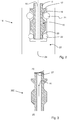
- FIG. 2 shows by way of example and schematically a connector 14 according to the prior art.
- This has a connecting element 15 forming a connection or connection port of the dialyzer 5 in the form of a male Hansenkonnektorelements.
- This is a per se known hollow cylinder-like element with a continuous flow channel 16.
- the connection element 15 is provided with a limited by a shoulder 17 pin 18, which serves a permanent arrangement of the connection element 15 on the dialyzer 5.
- a circumferential annular groove 19 is introduced into the outer contour of the connecting element 15.
- a step-shaped end-side shoulder 20 is introduced into the outer contour of the connecting element 15.
- the groove 19 and paragraph 20 are used to receive coupling elements in the form of balls 21, 22, which are radially inwardly biased radially inwardly, but fixed in the axial direction in a female Hansenkonnektorelement 23 are added. In this, a continuous flow channel 24 is formed.
- the female Hansen connector element 23 is fixedly connected to one of the liquid lines 3, 9, 10, 12 on the side opposite the male connection element 15.
- FIGS. 3 to 12 show various embodiments of the invention, wherein in the illustrated examples as a coupling principle always that of a Hansenkonnektors is used. This has already been described above with reference to the prior art and is generally known, so that a further description in this regard is dispensed with in the following examples and reference is made to the above statements. It should be noted that the invention can also be used with other coupling systems and connections and is not limited to the use of a Hansen connector. Further, on Place a male Hansenkonnektorelements be provided a female Hansenkonnektorelement and vice versa.
- FIG. 3 shows a connector 300 in the form of a male Hansen connector 300, similar to that in the Fig. 2 Part of an input-side connection or connection port 4, 11, not shown, of the dialyzer 5, via which the dialyzer blood, rinsing solution or dialysis fluid is supplied.
- the flow direction is in the FIG. 3 marked accordingly with an arrow.
- On the side facing away from the dialyzer 5 25 (below in FIG. 3 ) is a female connector 23 on the connector 300 from the line side 25 ago pushed and coupled.
- the flow channel 16 of the connector 300 is closed on the dialyzer 5 facing the end 26 of the connector 300 with a shut-off device in the form of a check valve 27 which is disposed or formed on the downstream side 25 and dialyzer side of the connector 300.
- the check valve 27 blocks in the outflow direction, ie out of the dialyzer 5, and releases the flow channel 16 in the inflow direction, ie into the dialyzer 5.
- the check valve 27 closes fluid-tight, as long as a pressure applied to it is less than a certain limit. When the limit value is exceeded, the check valve 27 opens and releases the flow channel 16.
- the check valve 27 is set or biased so that it opens only during operation of the pump 2 and by the expected pump pressure.
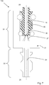
- FIG. 4 shows a connector 300 of the FIG. 3 similar connector 400 in the form of a male Hansen connector 400, similar to that in the Fig. 2 Part of an output-side connection or connection port 8, 13, not shown, of the dialyzer 5, via which blood or rinsing solution or dialysis fluid is removed from the dialyzer 5.
- the flow direction is in the FIG. 4 marked accordingly with an arrow and is opposite to the flow direction in the FIG. 3 ,
- On the side facing away from the dialyzer 5 bottom in FIG. 3 ) is a female connector 8, 13 on the connector 400 from the liquid line side 25 pushed forth and coupled.
- the flow channel 16 of the connector 400 is closed with a shut-off device in the form of a check valve 28 which on the downstream side or liquid line side 25 of the connector 400th arranged or formed.
- the check valve 28 blocks in the inflow direction, ie into the dialyzer 5, and releases the flow channel 16 in the outflow direction, ie out of the dialyzer 5, wherein the check valve 28 does not open by itself to the outside, but only at a corresponding delivery pressure, so that it closes the connection port 8 or 13 fluid-tight without pumping operation.
- FIG. 5 shows a connector 500, which is essentially a combination of the two in the Figures 3 and 4 represents embodiments shown.
- a bidirectional check valve or valve system 29 is provided in the flow channel 16, which operates in a pressure-dependent and direction-independent manner.
- the valve system 29 blocks both in the outflow direction and in the inflow direction, as long as a pressure difference applied to it is smaller than a certain limit value.
- the valve system 29 opens and releases the flow channel 16 in the direction of the pressure difference, ie from the high-pressure side in the direction of the low-pressure side.
- the connector 500 is suitable, regardless of whether it is located at an inlet or outlet of the dialyzer 5.
- a female connector 4, 8, 11, 13 is in turn pushed on the liquid line side 25 and coupled.
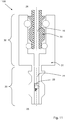
- FIG. 6 shows a connector 600.
- This has a male connector element 30 in the form of a male Hansen connector, similar to that in the Fig. 2 Part of an input or output side connection or connection port 4, 8, 11, 13 of the dialyzer 5, not shown, and a connector element 31 with a female coupling portion 32 and a male coupling portion 33, both in the manner of a Hansenkonnektors on.
- the male coupling portion 33 of the connector element 31 is provided with an in FIG. 5 not shown female Hansenkonnektorelements 23 one of the lines 3, 9, 10, 12 coupled.
- the flow direction is in the FIG.
- the connector 600 may be provided both at an input-side terminal 4, 11 and at an output-side terminal 8, 13 with a correspondingly reverse flow direction or is suitable for this purpose.
- the connector element 30 is a Flow channel 16 and in the connector element 31, a flow channel 24 is formed.
- the connector element 30 On its input side 25 (line side 25), the connector element 30 is closed with a shut-off device in the form of a, in particular mechanically actuated or displaceable, closing element 34.
- the closing element is arranged or formed on the side of the connector element 30 facing the connector element 31.
- the closing element 34 is automatically closed and thus blocks the flow channel 16 in disconnection in both directions fluid-tight. It releases the flow channel 16 in both directions as soon as a connection is effected by intended coupling of connector element 30 and connector element 31. This is effected by an opening element 36, which is formed on the connector element 31, by pressing or pressing the closure element 34 into an open position when it is properly connected.
- the opening element is a projection facing the connector element 30, which penetrates into the flow channel 16 of the connector element 30 and actuates or activates the closing element 34 or a similar blocking element provided therein so that it releases the flow channel 16 for both directions of flow.
- a female fitting 4, 8, 11, 13 of the dialyzer 5 is slidable on the coupling portion 33 of the connector element 31 from the liquid line side 25 and coupled.
- FIG. 7 shows a connector 700, which the connector 600 of FIG. 6 is similar, but differs in that instead of through the port 34 of the flow channel 16 of the connector element 30 is closed by a shut-off device in the form of a hydrophobic membrane 36 which on the liquid line side 25 or on the connector element 31 facing side of the connector element 30 or is trained.
- the membrane 36 is automatically closed and thus blocks the flow channel 16 in the event of disconnection both in the outflow direction and in the inflow direction. It releases the flow channel 16 in both directions as soon as a connection is effected by intended coupling of connector element 30 and connector element 31.
- FIGS. 8 to 12 each show a connector unit 800, 900, 1000, 1100 and 1200, each of the connector unit 600 of FIG. 6 and the connector unit 700 of FIG. 7 essentially correspond, so that reference is made to the descriptions there.
- FIGS. 6 and 7 Unlike the aforementioned embodiments of FIGS. 6 and 7 is at the connector element 31 of the embodiments of FIGS. 8 and 9 similar to the embodiment of the Figures 3 and 4 arranged a check valve 27 and 28, which blocks the flow channel 24 and releases. It is based on the corresponding remarks to the Figures 3 and 4 directed.
- the check valve 27 is arranged on the female coupling portion 32 on the side facing the connector element 30 side of the connector element 31 and opens at a corresponding pressure to the inside, ie to the connector element 30 out.
- the check valve 28 is arranged on the male coupling portion 33 on the liquid line side 25 and opens at a corresponding pressure to the outside, ie to one of the lines 3, 9, 10, 12 out.
- the connector element 31 acts as a sort of adapter and thus allows neither the connection 30 on the dialyzer nor the connector element 23 to be connected to the line 3, 9, 10, 12 to be changed or adapted in any way have to.
- the connector element 31 is attached on the one hand to the dialyzer port 30 and closes it.
- FIG. 10 In the embodiment of the FIG. 10 is in the connector element 31 of the connector unit 1000 in the region of its the lines 3, 9, 10, 12 end facing similar to the embodiment of the FIG. 6 a port 34 is arranged. Reference is made to the relevant explanations to the embodiment of the FIG. 6 directed.
- another connector element 38 is coupled to the connector element 31, likewise in the manner of a Hansenkonnetation, which, like the connector element 31, has a female coupling section 32 and a male coupling section 33.
- FIG. 11 In the embodiment of the FIG. 11 is in the connector element 31 of the connector unit 1100 in the region of its the lines 3, 9, 10, 12 facing the end 25 similar to the embodiment of FIG. 6 arranged a valve system 29 which operates pressure-dependent and direction independent. Reference is made to the relevant explanations to the embodiment of the FIG. 6 directed.
- FIG. 12 In the embodiment of the FIG. 12 is in the connector element 31 of the connector unit 1200 in the region of its the lines 3, 9, 10, 12 facing the end 25 similar to the embodiment of FIG. 7 a hydrophobic membrane 36 is arranged. Reference is made to the relevant explanations to the embodiment of the FIG. 7 directed.
- another connector element 38 is coupled to the connector element 31, likewise in the manner of a Hansenkonnetation, which, like the connector element 31, has a female coupling section 32 and a male coupling section 33.
- the main advantage of the in the Figures 10 and 12 can be seen in that the two connector elements 31 and 38 act as a kind of adapter or adapter set and thus allow neither the port 30 on the dialyzer nor the connector element 23 to be connected to the line 3, 9, 10, 12 in any Shape must be changed or adapted.
- any currently available system can be retrofitted.
- the connector element 31 is attached to the dialyzer port 30 and closes it and the connector element 38 is on the line 3, 9, 10, 12, more precisely attached to the connector element 23.
- the fluid connection between dialyzer 5 and line 3, 9, 10, 12 is opened or produced, since the connector element 38 when connecting the locking member 34 and 36 (compulsively) opens.
Landscapes
- Health & Medical Sciences (AREA)
- Heart & Thoracic Surgery (AREA)
- Life Sciences & Earth Sciences (AREA)
- Animal Behavior & Ethology (AREA)
- Engineering & Computer Science (AREA)
- Anesthesiology (AREA)
- Biomedical Technology (AREA)
- Hematology (AREA)
- Veterinary Medicine (AREA)
- Public Health (AREA)
- General Health & Medical Sciences (AREA)
- Vascular Medicine (AREA)
- Pulmonology (AREA)
- Urology & Nephrology (AREA)
- Cardiology (AREA)
- Emergency Medicine (AREA)
- External Artificial Organs (AREA)
Abstract
Description
- Die Erfindung betrifft eine Konnektoreinheit zum Verbinden eines Anschlussports eines Dialysators mit einer flüssigkeitsführenden Leitung, wobei die Konnektoreinheit einen durchgehenden Strömungskanal aufweist und einerseits des Strömungskanals einen Kupplungsabschnitt zur flüssigkeitsdichten Verbindung mit dem Anschlussport des Dialysators und andererseits des Strömungskanals einen Kupplungsabschnitt zur flüssigkeitsdichten Verbindung mit der flüssigkeitsführenden Leitung aufweist. Sie betrifft des Weiteren ein Verfahren zum Spülen eines Filterelements, insbesondere eines Dialysators für extrakorporale Blutbehandlungsverfahren, wie bspw. für Dialyse, Hämofiltration oder Ultrafiltration, unter Verwendung einer solchen Konnektoreinheit.
- Bekannte Dialysatoren weisen in der Regel vier Anschlüsse auf, mit denen sie einerseits mit einem Leitungssystem einer Dialysemaschine und anderseits mit einem mit einem Patienten verbundenen extrakorporalen Blutsystem angeschlossen werden. Die genannten Anschlüsse teilen sich auf in zwei Anschlüsse zur Verbindung mit dem extrakorporalen Blutsystem, über die zu reinigendes Blut zum Dialysator hin und vom Dialysator abgeführt wird, im Folgenden auch als Blutanschlüsse bezeichnet, und zwei Anschlüsse zur Verbindung mit der Dialysemaschine, über die Dialysierflüssigkeit zum Dialysator hin und vom Dialysator abgeführt wird, im Folgenden auch als Dialysierflüssigkeitsanschlüsse bezeichnet (siehe schematische Darstellung der
Fig. 1 ). - Vor dem Beginn eines Blutbehandlungsverfahrens ist es notwendig, den extrakorporalen Blutkreislauf einschließlich des Dialysatorfilters zu füllen und zu spülen, um die im extrakorporalen Kreislauf vorhandene Luft und ggf. Rückstände im Dialysator zu entfernen. Das Spülen geschieht in der Regel mit einer Kochsalzlösung. Hierzu wird ein vorgefüllter Beutel mit Kochsalzlösung verwendet, der manuell an das arterielle Blutschlauchende angeschlossen wird. Die Blutpumpe der Dialysemaschine fördert dann die Flüssigkeit durch den extrakorporalen Kreislauf. Die Kochsalzlösung tritt schließlich am venösen Ende des Blutschlauches in einen Abfallbeutel aus. Nach ausreichend umgewälzter Flüssigkeit ist der extrakorporale Kreislauf gespült und befüllt und damit für die Blutbehandlung vorbereitet.
- Um ein Eindringen von Verunreinigungen in den Dialysator und ein Auslaufen von darin ggf. vorhandener Flüssigkeit zu vermeiden sowie die Anschlüsse vor Beschädigung zu schützen, werden die Anschlüsse des Dialysators zunächst abgedeckt und verschlossen.
- Für den oben beschriebenen Spülvorgang müssen die Kappen, welche die Blutanschlüsse des Dialysators verschließen, entfernt werden. Diese werden in der Regel dann an den Dialysierflüssigkeitsanschlüssen angebracht. Nach dem Spülen werden die Kappen von den Dialysierflüssigkeitsanschlüssen entfernt, um daran die Zu- bzw. Ableitungen des Dialysierflüssigkeitsschlauchsystems anbringen zu können.
- Es gibt Lösungen, bei denen alle vier Anschlüsse eines Dialysators separat mit jeweils einer Kappe verschlossen sind. Zum Beispiel ist aus der
DE 38 255 73 A1 eine Verschlusskappe für Dialysatoren zur Verwendung bei deren Sterilisation, mit einem ersten und einem zweiten Kappenteil bekannt, von denen das erste Kappenteil an einem Dialysatorflansch anbringbar ist. Das zweite Kappenteil ist zwischen einer Offenstellung, in der der Durchtritt eines Sterilisationsmediums erfolgt, und einer Schließstellung bewegbar. Das erste Kappenteil weist eine Außenhülse, die den Dialysatorflansch im Einbauzustand steril dichtend außen übergreift, und ein rückwärtiges Teil auf, das mit einer In-line-Sterilisationseinrichtung in Strömungsverbindung bringbar ist. - Aus der
EP 1 000 632 A2 ist des Weiteren bekannt ein Verschlusselement zum sterilen Verschließen von Anschlüssen von Filtermodulen für Dialyse, Hämofiltration oder Ultrafiltration (eine sogenannte Sterilbarriere), welches Verschlusselement eine Wandung umfasst, die einen selbsttätig schließenden schlitzförmigen Einschnitt aufweist, der im geschlossenen Zustand keimdicht abschließt. Es sind Befestigungsmittel vorgesehen, die an die Wandung angrenzen und mittels derer das Verschlusselement mit einem Anschluss verbindbar ist. - Aus der
US 2009/0004053 A1 ist ein System bekannt, mit welchem eine medizinische Einrichtung automatisch gereinigt, desinfiziert, getestet und aktiviert werden kann. Das System umfasst einen Dialysator mit Bluteinlass und Blutauslass, eine Blutauslassleitung zur Verbindung mit dem Blutauslass mit einem maschinenseitigen und einem patientenseitigen Ende, eine Bluteinlassleitung zur Verbindung mit dem Bluteinlass mit einem maschinenseitigen und einem patientenseitigen Ende, ein Anschlussstück zur Verbindung mit dem Dialysator und eine Wiederverwendungseinrichtung zum Paaren mit dem Dialysator. Das Anschlussstück umfasst mehrere Verbinder, die zur Verbindung mit den patientenseitigen Enden der Blutein- und der Blutauslassleitung ausgebildet sind. Die Wiederverwendungseinrichtung ist zur Paarung mit dem Anschlussstück ausgebildet und eingerichtet, die Bluteinlassleitung, die Blutauslassleitung und den Dialysator zu reinigen. - Aus der
WO 2009/063281 A1 ist ein medizinischer Verbinder zum Verbinden von einer Dialysatzuleitung oder einer Dialysatableitung mit einem Fluidanschluss einer Dialysemaschine bekannt. Der Verbinder besitzt eine sichtbare Signaleinrichtung, die aus einem farbigen Streifen gebildet ist, der auf einem Zapfen angeordnet ist. Das Signal ist sichtbar, wenn sich der Zapfen in einer korrekten Eingriffsstellung mit einem externen Element befindet. Andernfalls ist der das Signal tragende Abschnitt des Zapfens abgesenkt, so dass das Signal nicht sichtbar ist und eine unkorrekte Verbindung anzeigt. Der Fluidanschluss der Dialysemaschine ist mit einem Sperrventil versehen. - Aus der
WO 2005/046785 A1 ist ein Konnektor zur Verbindung eines Dialysatports eines Blutdialysators mit einer Dialysat führenden Leitung bekannt. Der Konnektor weist einen ihn durchlaufender Hohlraum, ein den Hohlraum umschließendes erstes Ende, das geeignet ist, in den Hohlraum den Dialysatport aufzunehmen, und ein den Hohlraum umschließenden zweites Ende, das geeignet ist, mit der Dialysat führenden Leitung verbunden zu werden, auf. Am ersten Ende ist eine Aussparung mit einem von der Aussparung aufgenommenen Schiebeelement vorgesehen. Das Schiebeelement ist zwischen einer ersten und einer zweiten Position senkrecht zur Richtung des Hohlraums im ersten Ende verschiebbar. Das Schiebeelement durchdringt in der ersten Position den Hohlraum des ersten Endes nicht und engt in der zweiten Position den Hohlraum des ersten Endes ein, so dass der Konnektor mit dem Schiebeelement in der ersten Position auf den Dialysatport aufgesteckt wird und in der zweiten Position durch eine Hinterschneidung am Dialysatport an diesem arretiert werden kann. - Die aus dem Stand der Technik bekannte Verwendung von Kappen zum Verschließen von Dialysierflüssigkeitsanschlüssen eines Dialysators hat mehrere Nachteile:
- Bei dem vorstehend beschriebenen Wechseln der Kappen zum Spülen des Dialysators kann es in nachteiliger Weise zu Verschmutzung, Verformungen oder dem Verlust der Kappen kommen. Des Weiteren kann der Fall eintreten, dass die Kappen nicht wieder korrekt geschlossen werden. Wenn dem Anwender beim Wechsel eine Kappe herunterfällt, ist diese verschmutzt und kann nicht mehr verwendet werden. Wird sie dennoch irrtümlich verwendet, kann die Kappe den Anschluss und somit die Dialysierflüssigkeit verschmutzen, der Filter ist somit nicht mehr nutzbar. Eine Verwendung des Dialysefilters ist in einem solchen Fall nicht mehr möglich.
- Schließlich muss nach einem Spülen des Dialysators mit Spüllösung beim Anschließen von Dialysierflüssigkeitsleitungen an die Dialysierflüssigkeitsanschlüsse des Dialysators die Kappe entfernt werden. Hierbei tritt in der Regel noch im Dialysator vorliegende Spüllösung aus. Es wurde beobachtet, dass Anwender, um einen solchen Austritt zu minimieren oder zu verhindern, teilweise die Dialysierflüssigkeitsanschlüsse beispielsweise mit einem Finger temporär verschließen. Dies führt in nachteiliger Weise zu einer weiteren Möglichkeit von Kontamination.
- Ein weiterer Nachteil ist, dass der Zeitpunkt des Entfernens der Kappen unterschiedlich ist und von Anwender zu Anwender unterschiedlich gehandhabt wird. Dadurch können die Anschlüsse (sowohl Blutanschlüsse als auch Dialysierflüssigkeitsanschlüsse) offen, d.h. ungeschützt an der Maschine vorhanden sein.
- Ausgehend von dem vorstehend beschriebenen Stand der Technik liegt der vorliegenden Erfindung die Aufgabe zugrunde, die zuvor angeführten Nachteile zu beseitigen, insbesondere ein System zur Verfügung zu stellen, bei dem ein Entweichen von Flüssigkeit bei nicht mit dem Dialysator verbundenen Flüssigkeitsleitungen, zum Beispiel beim Anschließen des Dialysators, insbesondere von Spülflüssigkeit nach einem Spülen des Dialysators, verhindert werden kann. Vorzugsweise soll das System auf bestehende medizintechnische Einrichtungen adaptierbar sein, also auch bei bekannten Dialysatoren und Konnektionssystemen ein Entweichen von Flüssigkeit bei entkoppeltem Dialysator verhindern. Des Weiteren soll sichergestellt sein, dass auch bei entkoppeltem Dialysator dieser steril verschlossen ist.
- Die Aufgabe wird durch die Merkmale des Anspruchs 1 gelöst. Vorteilhafte Weiterbildungen sind Gegenstand von Unteransprüchen.
- Erfindungsgemäß wird ein Konnektor zum Verbinden eines Anschlusses eines Dialysators mit einer flüssigkeitsführenden Leitung bereitgestellt. Bei der flüssigkeitsführenden Leitung kann es sich um eine Blutzuleitung, eine Blutableitung, eine Dialysierflüssigkeitszuleitung und eine Dialysierflüssigkeitsableitung handeln. Der Konnektor weist einen Kupplungsabschnitt, insbesondere einen männlichen Hansenkonnektorabschnitt, zur flüssigkeitsdichten Verbindung mit einem Anschlusselement, insbesondere einer weiblichen Hansenkonnektoraufnahme, der entsprechenden Leitung auf. In einem Strömungskanal des Konnektors ist ein Absperrorgan oder Flusswiderstand integriert, das bzw. der unterhalb eines vorbestimmten Drucks und/oder bei nicht vorliegender (Fluid-)Verbindung zwischen dem Anschluss und der Leitung, d.h. wenn die Leitung nicht mit dem Konnektor verbunden ist, den Strömungsquerschnitt des Strömungskanals fluiddicht absperrt, und das bei vorliegender Verbindung zwischen dem Anschluss und der Leitung, d.h. wenn die Leitung mit dem Konnektor verbunden ist oder wird und/oder ein Fluidstrom mit einem vorbestimmten Druck oder höher aufgebaut wird, den Strömungsquerschnitt des Strömungskanals freigibt, d.h. einen Fluidstrom zwischen Dialysatoranschluss und Leitung zulässt.
- Dies bedeutet, dass der Konnektor den Strömungskanal verschließt, wenn keine Leitung angeschlossen ist bzw. noch keine Leitung angeschlossen worden ist. Der Strömungskanal ist zunächst verschlossen. Somit muss der Dialysator nicht mit einem zusätzlichen Verschluss oder Kappe verschlossen werden. Somit entfällt auch eine mögliche Gefahr einer Kontamination über die Kappe. Ferner wird dadurch verhindert, dass zwischen dem Entfernen der Kappe und dem Anschließen der Spüllösungsleitung der Anschluss, wenn auch kurz, offen und somit ungeschützt ist. Somit kann der Dialysator ohne Kappen, aber dennoch fluiddicht ausgeliefert bzw. vertrieben werden. Nach dem Spülen kann sichergestellt werden, dass die im Dialysator befindliche Spüllösung vor dem Anschließen der Dialysierflüssigkeitsab- und -zuleitungen nicht ausläuft.
- An den Konnektoren der Dialysierflüssigkeitszuleitung und Dialysierflüssigkeitsableitung, welche beim Spülvorgang offen bleiben, kann der Grenzdruck, ab welchen das jeweilige Absperrorgan öffnet, entsprechend so voreingestellt bzw. einstellbar sein, dass dieser höher als der beim Spülvorgang auf der Dialysierflüssigkeitsseite des Dialysators zu erwartende Fluiddruck ist.
- Der Konnektor kann in Form eines Adapters oder einer Konnektoreinheit, d.h. eines separaten Bauteils, ausgebildet sein, das an dem Anschluss(port) des Dialysators anbringbar ist, oder Teil des Anschlussports des Dialysators selbst sein bzw. mit diesem einstückig ausgebildet sein.
- Durch die Erfindung wird ein Konnektionssystem zum Anschließen von flüssigkeitsführenden Leitungen an entsprechende Ports eines Dialysators geschaffen, wobei das Konnektionssystem selbst Mittel enthält, die ein Ausströmen von Flüssigkeit verhindern, wenn keine dichte strömungstechnische Verbindung zwischen dem Dialysator und der flüssigkeitsführenden Leitung vorliegt. Im Falle einer separaten Konnektoreinheit ist diese je nach Ausbildung ihrer beiderseitigen Kupplungsabschnitte mit beliebigen Dialysatoren und Flüssigkeitsleitungen verwendbar, unabhängig von der Ausgestaltung der daran jeweils vorliegenden Anschlüsse.
- Erfindungsgemäß ist die Konnektoreinheit an einen Anschlussport eines Dialysators gekuppelt bzw. wird durch einen Anwender daran gekuppelt. Sobald die Konnektoreinheit und der Dialysator miteinander gekuppelt sind, besteht zwischen dem entsprechenden Anschluss des Dialysators und dem Strömungskanal der Konnektoreinheit eine strömungstechnische Verbindung. Diese ist mittels des im Strömungskanal erfindungsgemäß vorliegenden Sperrorgans gesperrt, solange nicht eine Flüssigkeitsleitung mit der Konnektoreinheit auf der dem Dialysator gegenüberliegenden Seite gekuppelt, insbesondere flüssigkeitsdicht gekuppelt ist. Der Strömungskanal in der Konnektoreinheit ist durch die Konnektoreinheit durchgehend ausgebildet und führt anders ausgedrückt von einer Konnektoreingangsseite zu einer Konnektorausgangsseite. Je nach Durchströmungsrichtung der Konnektoreinheit kann die Konnektoreingangsseite oder die Konnektorausgangsseite eingerichtet sein, um mit dem Anschlussport des Dialysators flüssigkeitsdicht verbunden werden zu können, und die Konnektorausgangsseite bzw. die Konnektoreingangsseite eingerichtet sein, um mit der flüssigkeitsführenden Leitung flüssigkeitsdicht verbunden werden zu können.
- Der Flusswiderstand bzw. das Absperrorgan ist derart ausgebildet, dass der Strömungskanal in dem Konnektor bzw. der Konnektoreinheit entsperrt ist bzw. wird, sobald eine Leitung an dem Dialysator angeschlossen ist und Flüssigkeit durch den Dialysator gepumpt wird. Damit bietet die Erfindung ein System, mit dem jeder Dialysator besonders einfach und effektiv abgedichtet sein bzw. werden kann, solange dieser nicht mit einer Leitung verbunden ist, welche Abdichtung zudem besonders einfach durch Erstellen einer strömungstechnischen Verbindung zwischen dem Dialysator und der flüssigkeitsführenden Leitung entsperrt werden kann. Dies ist in vorteilhafter Weise unabhängig vom jeweiligen Dialysator. Das erfindungsgemäße System lässt sich nämlich sowohl mit solchen Dialysatoren nutzen und verwenden, bei denen alle Anschlüsse oder ein Teil der Anschlüsse bereits mit einem diese selektiv sperrenden Portsystem versehen sind, als auch mit solchen Dialysatoren, bei denen kein Anschluss mit einer derartigen selektiven Abdichtung versehen ist. Dadurch ist die erfindungsgemäße Konnektoreinheit hochflexibel durch einen Anwender des Dialysators einsetzbar.
- Zum Beispiel wird zumindest ein Blutanschluss oder werden beide Blutanschlüsse eines Dialysators mit jeweils einer Konnektoreinheit nach der Erfindung gekuppelt bzw. deren Anschlüsse entsprechend ausgestaltet. Vorzugsweise wird zusätzlich oder alternativ ein Dialysierflüssigkeitsanschluss oder werden beide Dialysierflüssigkeitsanschlüsse des Dialysators ebenfalls mit jeweils einer Konnektoreinheit nach der Erfindung gekuppelt. Bei einem in der Regel vor einer Behandlung durchzuführenden Spülvorgang oder Primingvorgang können nun Flüssigkeitsleitungen in beliebiger Weise mit dem leitungsseitigen Kupplungsabschnitt der jeweiligen Konnektoreinheit gekuppelt und entkuppelt werden, ohne dass bei entkuppelter Leitung Flüssigkeit aus dem Dialysator ausströmen kann. Die aus dem Stand der Technik bekannte und eingangs beschriebene Verwendung von Kappen zum Verschluss der Dialysatoranschlüsse ist damit überflüssig.
- Durch die Erfindung kann insgesamt eine deutliche Erhöhung der Sicherheit einer extrakorporalen Blutbehandlung gegen eine Infektion des Patienten durch Kontamination bewirkt werden. Des Weiteren kann ein vereinfachtes Handling für den Anwender, verbunden mit einer geringeren Möglichkeit von Kontamination bewirkt werden. Schließlich können Fehlbedienungen vermieden werden. Letztendlich können Kosteneinsparungen bewirkt werden, da auf die aus dem Stand der Technik bekannten und dort erforderlichen Kappen verzichtet werden kann. Ein besonderer Vorteil aber ist, dass das erfindungsgemäße Konnektorsystem ja nach Ausbildung eine zusätzliche Sterilbarriere darstellen kann. Es kann insbesondere ein zusätzlicher Sauerstoffausschluss aus dem Dialysatorfilter erzielt werden.
- Vorteilhafte Ausführungsformen der Erfindung sind unter anderem in den Unteransprüchen beansprucht und werden nachfolgend näher erläutert.
- Unter einem Dialysator im Sinne der vorliegenden Beschreibung der Erfindung ist insbesondere ein Filtermodul für die extrakorporale Blutbehandlung zu verstehen. Unter einer flüssigkeitsführenden Leitung im Sinne der vorliegenden Beschreibung der Erfindung ist insbesondere eine Fluidzuleitung oder Fluidableitung zu verstehen, insbesondere eine Fluidzuleitung oder Fluidableitung einer Vorrichtung zur extrakorporalen Blutbehandlung, wie zum Beispiel eine Dialysemaschine.
- Von den Kupplungsabschnitten der Konnektoreinheit kann zumindest einer als Schnellverbindungskupplungsabschnitt, zum Beispiel als Hansenkupplungselement, ausgebildet sein. Vorzugsweise weist ein Kupplungsabschnitt der Konnektoreinheit eine weibliche Konnektoraufnahme auf, insbesondere eine weibliche Hansenkonnektoraufnahme. Diese ist zur Verbindung mit einem männlichen Gegenelement, insbesondere mit einem männlichen Hansenkonnektorelement ausgebildet und geeignet. Insbesondere der anschlussportseitige Kupplungsabschnitt des Konnektors kann mit einer solchen weiblichen Konnektoraufnahme, insbesondere einer weiblichen Hansenkonnektoraufnahme ausgebildet sein, so dass die Konnektoreinheit mit einem oftmals als männliches Gegenelement, insbesondere als männliches Hansenkonnektorgegenelement, ausgebildeten Anschlussport des Dialysators nach Art einer Hansen-Kupplung zu verbinden ist. Eine solche Verbindung kann in vorteilhafter Weise besonders einfach durch einen Anwender erstellt und gelöst werden und ist im Bereich von extrakorporalen Blutbehandlungseinrichtungen weit verbreitet, so dass von einer hohen Kompatibilität der Konnektoreinheit nach der Erfindung ausgegangen werden kann.
- Nach einer Ausführungsform der Erfindung weist die Konnektoreinheit zwei miteinander kuppelbare sowie voneinander entkuppelbare Konnektorelemente auf. Dabei kann insbesondere das eine Konnektorelement zur gegenseitigen Kopplung mit dem anderen Konnektorelement einen männlichen Kupplungsabschnitt und das andere Konnektorelement zur gegenseitigen Kopplung mit dem einen Konnektorelement einen weiblichen Kupplungsabschnitt aufweisen. Auf diese Weise sind die beiden Konnektorelemente der Konnektoreinheit besonders einfach und anwenderfreundlich miteinander kuppelbar und voneinander entkuppelbar. In zumindest einem der Konnektorelemente, vorzugsweise in dem dialysatorseitigen Konnektorelement, ist ein Absperrorgan nach der Erfindung angeordnet. Eine solche Ausbildung der Konnektoreinheit birgt besondere Vorteile in einem Fall, wenn ein Dialysator verwendet wird, dessen Anschlussports keine Sterilbarrieren oder ähnliche die Anschlüsse des Dialysators sperrende Einheiten aufweist. Die Konnektoreinheit wird in der zuvor beschriebenen Weise an einem Anschluss des Dialysators angekoppelt. Im Falle eines Spülvorgangs oder einer Primingprozedur verbleibt das anschlussportseitige Konnektorelement mit dem Anschlussport des Dialysators gekoppelt, während die Flüssigkeitsleitung von diesem getrennt wird, indem die beiden Konnektorelemente voneinander entkoppelt werden. Im Ergebnis kann auch bei einem nicht mit Sperreinrichtungen versehenen Dialysator ein Umstecken von Flüssigkeitsleitungen, zum Beispiel von den Blutanschlüssen auf die Dialysierflüssigkeitsanschlüsse und umgekehrt, erfolgen, ohne dass Flüssigkeit aus dem Dialysator austreten kann oder dessen Anschlüsse bei gelösten Flüssigkeitsleitungen offen und kontaminierbar wären. Man kann auch sagen, dass eines der Konnektorelemente als eine Art Adapter wirkt, der durch einen Anwender lösbar mit dem Konnektor verbindbar ist.
- Die entsprechenden Kupplungsabschnitte der Konnektoreinheit bzw. der Konnektorelemente können insbesondere als männliches Hansenkupplungselement und weibliches Hansenkupplungselement ausgebildet sein. Nach einer Ausführungsform besitzt jedes der beiden Konnektorelemente einen weiblichen Kupplungsabschnitt sowie einen männlichen Kupplungsabschnitt.
- Nach einer Ausführungsform der Erfindung ist das Absperrorgan druckabhängig und strömungsrichtungsunabhängig zu öffnen. Auf diese Weise kann das Absperrorgan unabhängig von der jeweiligen Anschlusskonfiguration und der dadurch bedingten Strömungsrichtung geöffnet werden. Im Falle von entkoppelten Flüssigkeitsleitungen ist die an dem Absperrorgan anliegende Druckdifferenz derart klein oder nicht vorhanden, dass das Absperrorgan den Strömungskanal absperrt und keine Flüssigkeit durch- und damit ausströmen kann. Bei angekuppelter Flüssigkeitsleitung liegt an dem Absperrorgan eine zu dessen Öffnen ausreichende Druckdifferenz an, und zwar unabhängig davon, ob es sich bei dem jeweiligen Anschluss um einen Zufluss oder Abfluss handelt. Diese Lösung ist sehr anwenderfreundlich.
- Nach einer weiteren Ausführungsform der Erfindung weist das Absperrorgan ein Rückschlagventil auf. Auf diese Weise kann die Konnektoreinheit bzw. der Konnektor gezielt mit nur einer Durchflussrichtung ausgebildet werden, was Fehlbedienungen zu vermeiden hilft. Um beide Flussrichtungen zu ermöglichen, kann das Absperrorgan auch als bidirektionales Rückschlagventil ausgebildet sein.
- Gemäß einem Aspekt der Erfindung kann das Absperrorgan mittels eines an einem Konnektorelement der anzuschließenden Leitung vorgesehenen Stellorgans beim Verbinden der Leitung mit dem Konnektor geöffnet werden. Zum Beispiel kann das Stellorgan das Absperrorgan in eine geöffnete Stellung bringen oder verdrängen.
- Es ist von besonderem Vorteil, wenn das Absperrorgan eine den Strömungsquerschnitt sperrende Membran umfasst, insbesondere eine hydrophobe Membran. Diese kann luftdurchlässig sein. Die Membran kann derart ausgebildet sein, dass sie bei einer bestimmten an ihr anliegenden Druckdifferenz öffnet, zum Beispiel reißt oder platzt, oder dass sie nur durch Anstechen mit einem dazu vorgesehenen Anstechelement öffnet. Vorzugsweise ist die Membran derart beschaffen, dass sie bei Diskonnektion der Flüssigkeitsleitung selbstständig wieder schließt, zum Beispiel nach Art eines in der Medizintechnik allgemein bekannten Zugangsports.
- Das Absperrorgan ist vorzugsweise bei allen Ausführungsformen derart beschaffen, dass es mehrfach verwendbar ist, d.h. bei gekoppelter Flüssigkeitsleitung offen ist und bei entkoppelter Flüssigkeitsleitung sperrt, dies vorzugsweise weitgehend unabhängig von der Anzahl bereits getätigter Kopplungsvorgänge.
- Bei einer Ausführungsform kann die Konnektoreinheit ein Öffnungselement zum Öffnen des Absperrorgans aufweisen. Das Öffnungselement ist vorzugsweise in einem der beiden Konnektorelemente angeordnet. Es ist derart ausgebildet, dass es beim Koppeln der Flüssigkeitsleitung an den Dialysator das Absperrorgan zwangsläufig durchsticht und öffnet. Das Öffnungselement ist vorzugsweise als Anstechelement ausgebildet. Vorzugsweise ist das weibliche Konnektorelement ausgebildet, das Absperrorgan zu aktivieren.
- Anders ausgedrückt betrifft die Erfindung die Integration eines Absperrorgans in ein Konnektorsystem, zum Beispiel durch einen Konnektor mit zumindest einer der folgenden Eigenschaften:
- Der Konnektor macht eine Verwendung von Kappen sowie ein Zuhalten und Abdichten von diskonnektierten Anschlüssen per Daumen obsolet.
- Der Konnektor kann aus Rückschlagventilen bestehen und mit allen Geräteherstellern kompatibel sein.
- Der Konnektor kann von weiblichem Hansen-Konnektor aktiviert werden. Die Erfindung schließt einen Konnektor an einem männlichem Konnektor und einen Aktivator an einem weiblichem Hansen-Konnektor ein (weiblicher Hansen-Konnektor bleibt kompatibel zu anderen männlichen Konnektoren).
- Der Konnektor kann druckabhängig und richtungsunabhängig öffnen.
- Die Absperrfunktion kann durch den Einbau einer Membran erfolgen. Die Membran kann hydrophob aufgebaut und damit luftdurchlässig sein und mit Anschluss eines entsprechend ausgebildeten zweiten Konnektors durchstochen werden.
- Die Erfindung betrifft außerdem ein Verfahren zum Spülen eines Dialysators für eine extrakorporale Blutbehandlung, welcher Dialysator einen Blutzuleitungsanschluss, einen Blutableitungsanschluss, einen Dialysierflüssigkeitszuleitungsanschluss und einen Dialysierflüssigkeitsableitungsanschluss aufweist, wobei an zumindest einem Anschluss des Dialysators, vorzugsweise an jedem Anschluss des Dialysators, ein Konnektor nach einem der vorstehenden Ansprüche, angeordnet ist und der Dialysator gespült wird, indem eine Spülflüssigkeitszuleitung mit dem an den Blutzuleitungsanschluss angeordneten Konnektor gekoppelt wird und eine Spülflüssigkeitsableitung mit dem an den Blutableitungsanschluss angeordneten Konnektor gekoppelt wird.
- Durch das Verfahren nach der Erfindung ist sichergestellt, dass bei einem Entkoppeln oder Lösen einer der Flüssigkeitsleitungen stets die erfindungsgemäße Konnektoreinheit oder zumindest das den Absperrorgan beinhaltende Konnektorelement an dem entsprechenden Anschluss des Dialysators gekoppelt verbleibt und so ein Auslaufen von Flüssigkeit daraus verhindert. Anders ausgedrückt wird durch ein statisch mit dem Dialysator verbundenes Absperrorgan ein Austreten von Flüssigkeit, insbesondere von Spüllösung beim initialen Spülen, verhindert. Der Anwender muss hierzu keine weiteren Handhabungsschritte aktiv durchführen. Dies führt zu erhöhter Sicherheit, vereinfachter Anwendbarkeit und geringeren Verunreinigungen.
- Die Erfindung wird im Folgenden anhand beispielhafter, nicht einschränkender und in den angehängten Figuren gezeigter Ausführungsformen näher erläutert. Dabei zeigt:
-
Figur 1 eine schematische Darstellung eines Fluidsystems einer Vorrichtung zur extrakorporalen Blutbehandlung, -
Figur 2 eine schematische Darstellung einer Dialysator-Verbindung nach dem Stand der Technik, -
Figur 3 eine schematische Darstellung einer ersten Ausführungsform der Erfindung in einer Schnittansicht, -
Figur 4 eine schematische Darstellung einer zweiten Ausführungsform der Erfindung in einer Schnittansicht, -
Figur 5 eine schematische Darstellung einer dritten Ausführungsform der Erfindung in einer Schnittansicht, -
Figur 6 eine schematische Darstellung einer vierten Ausführungsform der Erfindung in einer Schnittansicht, -
Figur 7 eine schematische Darstellung einer fünften Ausführungsform der Erfindung in einer Schnittansicht, -
Figur 8 eine schematische Darstellung einer sechsten Ausführungsform der Erfindung in einer Schnittansicht, -
Figur 9 eine schematische Darstellung einer siebten Ausführungsform der Erfindung in einer Schnittansicht, -
Figur 10 eine schematische Darstellung einer achten Ausführungsform der Erfindung in einer Schnittansicht, -
Figur11 eine schematische Darstellung einer neunten Ausführungsform der Erfindung in einer Schnittansicht und -
Figur 12 eine schematische Darstellung einer zehnten Ausführungsform der Erfindung in einer Schnittansicht. -
Figur 1 zeigt beispielhaft einen Ausschnitt einer Vorrichtung zur extrakorporalen Blutbehandlung, hier einer Dialysevorrichtung. Gezeigt ist im Wesentlichen der gesamte extrakorporale Blutkreislauf der Vorrichtung. Dieser weist eine arterielle Blutleitung 1 auf, mittels der Blut von einem nicht gezeigten Patienten zu einer Peristaltikpumpe 2 der Behandlungsvorrichtung geführt wird. Hochdruckseitig der Peristaltikpumpe 2 führt eine Hochdruckblutleitung oder Blutzuleitung 3 unter Hochdruck stehendes aber noch unbehandeltes Blut zu einem Blutzuleitungsanschluss 4 eines Dialysators 5. Hinter der Peristaltikpumpe 2 können mittels einer Zuleitung 6 und einer Pumpe 7 Zusatzstoffe in das im System befindliche Blut gegeben werden, z.B. Gerinnungshemmer oder Heparin zur Blutverdünnung. Im Dialysator 5 wird Blut in bekannter Weise mittels der Dialysierflüssigkeit behandelt, z.B. gereinigt. Behandeltes Blut wird über einen Blutableitungsanschluss 8 vom Dialysator 5 über eine venöse Blutleitung oder Blutableitung 9 zurück zum Patienten geleitet. - Dem Dialysator 5 wird frische Dialysierflüssigkeit über eine Dialysierflüssigkeitszuleitung 10, die mit einem Dialysierflüssigkeitszuleitungsanschluss 11 des Dialysators 5 gekoppelt ist, zugeführt. Verbrauchte Dialysierflüssigkeit wird über eine Dialysierflüssigkeitsableitung 12, die mit einem Dialysierflüssigkeitsableitungsanschluss 13 des Dialysators 5 gekoppelt ist, aus diesem entfernt und einer nicht dargestellten Entsorgung oder Aufbereitung zugeführt. Aus
Figur 1 geht hervor, dass der Dialysator 5 im Gegenstrom von Blut und Dialysierflüssigkeit durchströmt wird. - Vor Beginn einer Behandlung wird der Dialysators 5 mit einer Spüllösung über die Blutanschlüsse 4 und 8 gespült. Hierzu wird in der Regel ein vorgefüllter Beutel mit Kochsalzlösung manuell an das arterielle Blutschlauchende angeschlossen und mittels der Peristaltikpumpe 2 diese durch den extrakorporalen Kreislauf einschließlich des Dialysators 5 gepumpt. Die Kochsalzlösung tritt schließlich am venösen Ende des Blutschlauches 9, z. B in einen Abfallbeutel aus. Nach ausreichend umgewälzter Flüssigkeit ist der extrakorporale Kreislauf gespült und befüllt und damit für die Blutbehandlung vorbereitet.
-
Figur 2 zeigt beispielhaft und schematisch einen Konnektor 14 nach dem Stand der Technik. Dieser weist ein einen Anschluss oder Anschlussport des Dialysators 5 ausbildendes Anschlusselement 15 in Form eines männlichen Hansenkonnektorelements auf. Dieses ist ein an sich bekanntes hohlzylinderartiges Element mit einem durchgehenden Strömungskanal 16. An der dialysatornahen Seite ist das Anschlusselement 15 mit einem von einer Schulter 17 begrenzten Zapfen 18 versehen, der einer dauerhaften Anordnung des Anschlusselements 15 am Dialysator 5 dient. Auf der vom Zapfen 18 abgewandten Seite der Schulter 17 ist eine umlaufende Ringnut 19 in die Außenkontur des Anschlusselements 15 eingebracht. Leitungsseitig ist ein stufenförmiger endseitiger Absatz 20 in die Außenkontur des Anschlusselements 15 eingebracht. Die Nut 19 und Absatz 20 dienen der Aufnahme von Kopplungselementen in Form von Kugeln 21, 22, die in radialer Richtung beweglich radial nach innen vorgespannt, jedoch in axialer Richtung fixiert in einem weiblichen Hansenkonnektorelement 23 aufgenommen sind. In diesem ist ein durchgehender Strömungskanal 24 ausgebildet. Das weibliche Hansenkonnektorelement 23 ist auf der dem männlichen Anschlusselement 15 gegenüberliegenden Seite fest mit einer der Flüssigkeitsleitungen 3, 9, 10, 12 verbunden. AusFigur 2 geht offensichtlich hervor, dass bei einer Diskonnektion der Flüssigkeitsleitung 3, 9, 10, 12 vom Dialysator durch Entkoppeln des weiblichen Hansenkonnektorelements 23 vom Anschlusselement 15 dessen Strömungskanal 16 offen ist und bleibt, so dass in nachteiliger Weise Flüssigkeit aus dem Inneren des Dialysators 5 herausfließen kann und des Weiteren Verschmutzungen in das Innere des Dialysators 5 eindringen und diesen kontaminieren können. - Die
Figuren 3 bis 12 zeigen verschiedene Ausführungsformen der Erfindung, wobei in den dargestellten Beispielen als Kupplungsprinzip stets das eines Hansenkonnektors genutzt wird. Dieses wurde vorstehend bereits mit Bezug zum Stand der Technik beschrieben und ist allgemein bekannt, so dass auf eine weitere diesbezügliche Beschreibung bei den nachfolgenden Beispielen verzichtet wird und auf die vorstehenden Ausführungen verwiesen wird. Es sei angemerkt, dass die Erfindung auch mit anderen Kupplungssystemen und Verbindungen genutzt werden kann und nicht auf die Verwendung eines Hansenkonnektors beschränkt ist. Ferner kann an Stelle eines männlichen Hansenkonnektorelements ein weibliches Hansenkonnektorelement vorgesehen sein und umgekehrt. - Die
Figur 3 zeigt einen Konnektor 300 in Form eines männlichen Hansenkonnektors 300, der ähnlich wie in derFig. 2 Teil eines nicht dargestellten eingangsseitigen Anschlusses oder Anschlussports 4, 11 des Dialysators 5, über welchen dem Dialysator Blut, Spüllösung oder Dialysierflüssigkeit zugeführt wird. Die Strömungsrichtung ist in derFigur 3 entsprechend mit einem Pfeil gekennzeichnet. Auf der dem Dialysator 5 abgewandten Seite 25 (unten inFigur 3 ) ist ein weibliches Anschlussstück 23 auf den Konnektor 300 von der Leitungsseite 25 her aufschiebbar und koppelbar. Der Strömungskanal 16 des Konnektors 300 ist auf der dem Dialysator 5 zugewandten Ende 26 des Konnektors 300 mit einem Absperrorgan in Form eines Rückschlagventils 27 verschlossen, das auf der stromabwärtigen Seite 25 bzw. Dialysatorseite des Konnektors 300 angeordnet oder ausgebildet ist. Das Rückschlagventil 27 sperrt in Ausströmrichtung, d.h. aus dem Dialysator 5 heraus, und gibt den Strömungskanal 16 in Einströmrichtung, d.h. in den Dialysator 5 hinein, frei. Das Rückschlagventil 27 sperrt fluiddicht ab, solange eine an ihm anliegenden Druckdifferenz kleiner als ein bestimmter Grenzwert ist. Bei Überschreiten des Grenzwerts öffnet das Rückschlagventil 27 und gibt den Strömungskanal 16 frei. Das Rückschlagventil 27 ist so eingestellt bzw. vorgespannt, dass es erst beim Betrieb der Pumpe 2 und durch den zu erwartenden Pumpendruck öffnet. -
Figur 4 zeigt einen dem Konnektor 300 derFigur 3 ähnelnden Konnektor 400 in Form eines männlichen Hansenkonnektors 400, der ähnlich wie in derFig. 2 Teil eines nicht dargestellten ausgangsseitigen Anschlusses oder Anschlussports 8, 13 des Dialysators 5, über welchen Blut bzw. Spüllösung oder Dialysierflüssigkeit vom Dialysator 5 abgeführt wird. Die Strömungsrichtung ist in derFigur 4 entsprechend mit einem Pfeil gekennzeichnet und ist entgegengesetzt zur Strömungsrichtung in derFigur 3 . Auf der dem Dialysator 5 abgewandten Seite (unten inFigur 3 ) ist ein weibliches Anschlussstück 8, 13 auf den Konnektor 400 von der Flüssigkeitsleitungsseite 25 her aufschiebbar und koppelbar. Der Strömungskanal 16 des Konnektors 400 ist mit einem Absperrorgan in Form eines Rückschlagventils 28 verschlossen, das auf der stromabwärtigen Seite bzw. Flüssigkeitsleitungsseite 25 des Konnektors 400 angeordnet oder ausgebildet ist. Das Rückschlagventil 28 sperrt in Einströmrichtung, d.h. in den Dialysator 5 hinein, und gibt den Strömungskanal 16 in Ausströmrichtung, d.h. aus dem Dialysator 5 heraus, frei, wobei das Rückschlagventil 28 nicht von alleine nach außen öffnet, sondern nur bei entsprechendem Förderdruck, so dass es ohne Pumpbetrieb den Anschlussport 8 bzw. 13 fluiddicht verschließt. -
Figur 5 zeigt einen Konnektor 500, der im Wesentlichen eine Kombination der beiden in denFiguren 3 und4 gezeigten Ausführungsformen darstellt. Anstelle eines bei entsprechendem Druck nach innen öffnenden Rückschlagventils 27 oder eines bei entsprechendem Druck nach außen öffnenden Rückschlagventils 28 ist in dem Strömungskanal 16 ein bidirektionales Rückschlagventil bzw. Ventilsystem 29 vorgesehen, das druckabhängig und richtungsunabhängig arbeitet. Das Ventilsystem 29 sperrt sowohl in Ausströmrichtung als auch in Einströmrichtung, solange eine an ihm anliegenden Druckdifferenz kleiner als ein bestimmter Grenzwert ist. Bei Überschreiten des Grenzwerts öffnet das Ventilsystem 29 und gibt den Strömungskanal 16 in Richtung der Druckdifferenz, d.h. von der Hochdruckseite in Richtung der Niederdruckseite, frei. Mit anderen Worten der Konnektor 500 eignet sich, unabhängig davon, ob er sich an einem Zulauf oder Ablauf des Dialysators 5 befindet. Ein weibliches Anschlussstück 4, 8, 11, 13 ist wiederum auf der Flüssigkeitsleitungsseite 25 aufschiebbar und koppelbar. - Die
Figur 6 zeigt einen Konnektor 600. Dieser weist ein männliches Konnektorelement 30 in Form eines männlichen Hansenkonnektors, der ähnlich wie in derFig. 2 Teil eines nicht dargestellten eingangs- oder ausgangsseitigen Anschlusses oder Anschlussports 4, 8, 11, 13 des Dialysators 5 ist, und ein Konnektorelement 31 mit einem weiblichen Kupplungsabschnitt 32 und einem männlichen Kupplungsabschnitt 33, beide jeweils nach Art eines Hansenkonnektors, auf. Der männliche Kupplungsabschnitt 33 des Konnektorelements 31 ist mit einem inFigur 5 nicht dargestellten weiblichen Hansenkonnektorelements 23 einer der Leitungen 3, 9, 10, 12 koppelbar. Die Strömungsrichtung ist in derFigur 6 wieder gekennzeichnet, wobei der Konnektor 600 sowohl an einem eingangseitigen Anschluss 4, 11 als auch an einem ausgangsseitigen Anschluss 8, 13 mit entsprechend umgekehrter Strömungsrichtung vorgesehen sein kann bzw. sich hierfür eignet. In dem Konnektorelement 30 ist ein Strömungskanal 16 und in dem Konnektorelement 31 ist ein Strömungskanal 24 ausgebildet. - An seiner Eingangsseite 25 (Leitungsseite 25) ist das Konnektorelement 30 mit einem Absperrorgan in Form eines, insbesondere mechanisch betätig- oder verschiebbaren, Schließelements 34 verschlossen. Das Schließelement ist auf der dem Konnektorelement 31 zugewandten Seite des Konnektorelements 30 angeordnet oder ausgebildet. Das Schließelement 34 ist selbsttätig geschlossen und sperrt damit den Strömungskanal 16 bei Diskonnektion in beide Richtungen fluiddicht ab. Er gibt den Strömungskanal 16 in beide Richtungen frei, sobald eine Konnektion durch bestimmungsgemäßes Koppeln von Konnektorelement 30 und Konnektorelement 31 bewirkt ist. Dies wird durch ein Öffnungselement 36, das am Konnektorelement 31 ausgebildet ist, bewirkt, indem dieses bei bestimmungsgemäßer Konnektion das Schließelement 34 in eine geöffnete Stellung drängt oder betätigt. Bei dem Öffnungselement handelt es sich um einen dem Konnektorelement 30 zugewandten Vorsprung, der in den Strömungskanal 16 des Konnektorelements 30 eindringt und dort das darin vorgesehene Schließelement 34 oder ein ähnliches Sperrorgan betätigt oder aktiviert, so dass es den Strömungskanal 16 für beide Strömungsrichtungen freigibt. Ein weibliches Anschlussstück 4, 8, 11, 13 des Dialysators 5 ist auf den Kupplungsabschnitt 33 des Konnektorelements 31 von der Flüssigkeitsleitungsseite 25 aufschiebbar und koppelbar.
- Die
Figur 7 zeigt einen Konnektor 700, welcher dem Konnektor 600 derFigur 6 ähnelt, sich jedoch darin unterscheidet, dass anstelle durch den Port 34 der Strömungskanal 16 des Konnektorelements 30 durch ein Absperrorgan in Form einer hydrophoben Membran 36 verschlossen ist, welche auf der Flüssigkeitsleitungsseite 25 bzw. auf der dem Konnektorelement 31 zugewandten Seite des Konnektorelements 30 angeordnet oder ausgebildet ist. Die Membran 36 ist selbsttätig geschlossen und sperrt damit den Strömungskanal 16 bei Diskonnektion sowohl in Auströmrichtung als auch in Einströmrichtung. Sie gibt den Strömungskanal 16 in beide Richtungen frei, sobald eine Konnektion durch bestimmungsgemäßes Koppeln von Konnektorelement 30 und Konnektorelement 31 bewirkt ist. Dies wird durch ein Öffnungselement 37 in Form einer Anstechnadel, das am Konnektorelement 31 ausgebildet ist, bewirkt, indem dieses bei bestimmungsgemäßer Konnektion die Membran 36 durchsticht und öffnet. Beim Entkoppeln der Konnektorelemente 30 und 31 schließt die hydrophobe Membran 36 von selbst fluiddicht ab. - Die
Figuren 8 bis 12 zeigen jeweils eine Konnektoreinheit 800, 900, 1000, 1100 bzw. 1200, die jeweils der Konnektoreinheit 600 derFigur 6 sowie der Konnektoreinheit 700 derFigur 7 im Wesentlichen entsprechen, so dass auf die dortigen Beschreibungen verwiesen wird. - Anders als die vorgenannten Ausführungsformen der
Figuren 6 und7 ist an dem Konnektorelement 31 der Ausführungsformen derFiguren 8 und9 ähnlich wie in der Ausführungsform derFiguren 3 und4 ein Rückschlagventil 27 bzw. 28 angeordnet, das den Strömungskanal 24 sperrt bzw. frei gibt. Es wird auf die entsprechenden Ausführungen zu denFiguren 3 und4 verwiesen. Bei der Ausführungsform derFigur 8 ist das Rückschlagventil 27 am weiblichen Kupplungsabschnitt 32 auf der dem Konnektorelement 30 zugewandten Seite des Konnektorelements 31 angeordnet und öffnet bei entsprechendem Druck nach Innen, d.h. zum Konnektorelement 30 hin. Bei der Ausführungsform derFigur 9 ist das Rückschlagventil 28 am männlichen Kupplungsabschnitt 33 auf der Flüssigkeitsleitungsseite 25 angeordnet und öffnet bei entsprechendem Druck nach Außen, d.h. zu einer der Leitungen 3, 9, 10, 12 hin. - Der wesentliche Vorteil der in den
Figuren 8 und9 gezeigten Ausführungsformen ist darin zu sehen, dass das Konnektorelement 31 gewissermaßen als eine Art Adapter fungiert und somit ermöglicht, dass weder der Anschluss 30 am Dialysator noch das Konnektorelement 23 an der anzuschließenden Leitung 3, 9, 10, 12 in irgendeiner Form verändert oder angepasst werden müssen. Somit kann mit dem Konnektor 800 bzw. 900 jedes derzeit verfügbare System nachgerüstet werden. Das Konnektorelement 31 wird einerseits am Dialysatoranschluss 30 angebracht und verschließt diesen. Beim Verbinden des Konnektorelements 31 mit einem Konnektorelement 23 der Leitung 3, 9, 10, 12 und anschließendem Pumpen von Flüssigkeit durch die Leitungen wird die Fluidverbindung zwischen Dialysator 5 und Leitung 3, 9, 10, 12 geöffnet bzw. hergestellt, da der Förderdruck das bzw. die Rückschlagventile 27, 28, 29 öffnet. - Bei der Ausführungsform der
Figur 10 ist in dem Konnektorelement 31 der Konnektoreinheit 1000 im Bereich von dessen den Leitungen 3, 9, 10, 12 zugewandtem Ende ähnlich der Ausführungsform derFigur 6 ein Port 34 angeordnet. Es wird auf die diesbezüglichen Erläuterungen zur Ausführungsform derFigur 6 verwiesen. Leitungsseitig ist auf das Konnektorelement 31 ein weiteres Konnektorelement 38 angekoppelt, ebenfalls nach Art einer Hansenkonnektion, das wie auch das Konnektorelement 31 einen weiblichen Kupplungsabschnitt 32 und einem männlichen Kupplungsabschnitt 33 aufweist. - Bei der Ausführungsform der
Figur 11 ist in dem Konnektorelement 31 der Konnektoreinheit 1100 im Bereich von dessen den Leitungen 3, 9, 10, 12 zugewandtem Ende 25 ähnlich der Ausführungsform derFigur 6 ein Ventilsystem 29 angeordnet, das druckabhängig und richtungsunabhängig arbeitet. Es wird auf die diesbezüglichen Erläuterungen zur Ausführungsform derFigur 6 verwiesen. - Bei der Ausführungsform der
Figur 12 ist in dem Konnektorelement 31 der Konnektoreinheit 1200 im Bereich von dessen den Leitungen 3, 9, 10, 12 zugewandtem Ende 25 ähnlich der Ausführungsform derFigur 7 eine hydrophobe Membran 36 angeordnet. Es wird auf die diesbezüglichen Erläuterungen zur Ausführungsform derFigur 7 verwiesen. Leitungsseitig ist auf das Konnektorelement 31 ein weiteres Konnektorelement 38 angekoppelt, ebenfalls nach Art einer Hansenkonnektion, das wie auch das Konnektorelement 31 einen weiblichen Kupplungsabschnitt 32 und einem männlichen Kupplungsabschnitt 33 aufweist. - Der wesentliche Vorteil der in den
Figuren 10 und12 gezeigten Ausführungsformen ist darin zu sehen, dass die beiden Konnektorelemente 31 und 38 gewissermaßen als eine Art Adapter oder Adapterset fungieren und somit ermöglichen, dass weder der Anschluss 30 am Dialysator noch das Konnektorelement 23 an der anzuschließenden Leitung 3, 9, 10, 12 in irgendeiner Form verändert oder angepasst werden müssen. Somit kann mit dem Konnektor 1000 bzw. 1200 bzw. mit den Konnektorelementen 31 und 38 jedes derzeit verfügbare System nachgerüstet werden. Das Konnektorelement 31 wird am Dialysatoranschluss 30 angebracht und verschließt diesen und das Konnektorelement 38 wird an der Leitung 3, 9, 10, 12, genauer gesagt an dem Konnektorelement 23, angebracht. Beim Verbinden der beiden Konnektorelemente wird die Fluidverbindung zwischen Dialysator 5 und Leitung 3, 9, 10, 12 geöffnet bzw. hergestellt, da das Konnektorelement 38 beim Verbinden das Sperrorgan 34 bzw. 36 (zwanghaft) öffnet.
Claims (9)
- Konnektor (300) zum Verbinden eines Dialysators (5) mit einer flüssigkeitsführenden Leitung (3, 9, 10, 12), wobei der Konnektor (300) einen Kupplungsabschnitt (15, 33), insbesondere einen männlichen Hansenkonnektorabschnitt, zur flüssigkeitsdichten Verbindung mit einem Konnektorelement (23), insbesondere einer weiblichen Hansenkonnektoraufnahme, der Leitung (3, 9, 10, 12) aufweist,
dadurch gekennzeichnet, dass
in einem Strömungskanal (16; 24) des Konnektors ein Absperrorgan (27, 28, 29, 34, 36) integriert ist, das unterhalb eines vorbestimmten Drucks oder bei nicht vorliegender Fluidverbindung zwischen dem Dialysator (5) und der Leitung (3, 9, 10, 12) den Strömungsquerschnitt des Strömungskanals (16, 24) absperrt. - Konnektor (300, 400, 500) nach Anspruch 1, dadurch gekennzeichnet, dass das Absperrorgan (27, 28, 29) strömungsrichtungsunabhängig zu öffnen ist, vorzugsweise das Absperrorgan ein bidirektionales Rückschlagventil (29) aufweist.
- Konnektor (600) nach Anspruch 1, dadurch gekennzeichnet, dass das Absperrorgan (34) mit einem an einem Konnektorelement (23) der anzuschließenden Leitung (3, 9, 10, 12) vorgesehenen Stellorgan derart zusammenwirkt, dass es beim Verbinden der Leitung (3, 9, 10, 12) mit dem Dialysator (5) geöffnet wird.
- Konnektor (700) nach Anspruch 1, dadurch gekennzeichnet, dass das Absperrorgan (36) eine den Strömungsquerschnitt absperrende Membran (37) umfasst, insbesondere eine hydrophobe Membran, welche mit einem an einem Konnektorelement (32) der anzuschließenden Leitung (3, 9, 10, 12) vorgesehenen Vorsprungselement (37), insbesondere Anstechelement, derart zusammenwirkt, dass es beim Verbinden der Leitung (3, 9, 10, 12) mit dem Dialysator (5) durchstoßen wird.
- Konnektor (800, 900) nach einem der vorhergehenden Ansprüche,
dadurch gekennzeichnet, dass der Konnektor ferner einen Kupplungsabschnitt (32, 38), insbesondere Schnellkupplungsabschnitt, zur lösbaren und flüssigkeitsdichten Verbindung mit dem Dialysator (5) aufweist. - Konnektor (600) nach einem der vorhergehenden Ansprüche, dadurch gekennzeichnet, dass der Konnektor zwei miteinander kuppelbare sowie voneinander entkuppelbare Konnektorelemente (30, 31) aufweist, wobei insbesondere das erste Konnektorelement (30) zur gegenseitigen Kopplung einen männlichen Kupplungsabschnitt und das zweite Konnektorelement (31) zur gegenseitigen Kopplung einen weiblichen Kupplungsabschnitt (32) aufweist.
- Konnektor (1000; 1200) nach einem der Ansprüche 1 bis 5, dadurch gekennzeichnet, dass der Konnektor zwei miteinander kuppelbare sowie voneinander entkuppelbare Konnektorelemente (31, 38) aufweist, wobei das erste Konnektorelement (31) eine weibliche Hansenkonnektoraufnahme (32) zur Kopplung mit einem entsprechenden an dem Anschluss (15) des Dialysators (5) ausgebildeten männlichen Hansenkonnektorelement (30) aufweist und das zweite Konnektorelement (38) ein männliches Hansenkonnektorelement zur Kopplung mit einer entsprechenden an der anzuschließenden Leitung ausgebildeten weiblichen Hansenkonnektoraufnahme (23) aufweist, wobei das Sperrorgan (34, 36) in dem ersten Konnektorelement (31) vorgesehen ist.
- Dialysator (5) für eine extrakorporale Blutbehandlung mit einem Blutzuleitungsanschluss (4), einem Blutableitungsanschluss (8), einem Dialysierflüssigkeitszuleitungsanschluss (11) und einem Dialysierflüssigkeitsableitungsanschluss (13), wobei ein Konnektor (300) nach einem der vorstehenden Ansprüche einstückig mit dem Dialysator ausgebildet ist oder an zumindest einem Anschluss (4, 8, 11, 13) des Dialysators (5) lösbar angebracht ist.
- Verfahren zum Spülen eines Filterelements (5), insbesondere eines Dialysators (5) für eine extrakorporale Blutbehandlung, welcher Dialysator (5) einen Blutzuleitungsanschluss (4), einen Blutableitungsanschluss (8), einen Dialysierflüssigkeitszuleitungsanschluss (11) und einen Dialysierflüssigkeitsableitungsanschluss (13) aufweist, wobei an zumindest einem Anschluss (4, 8, 11, 13) des Dialysators (5), vorzugsweise an jedem Anschluss (4, 8, 11, 13) des Dialysators (5), ein Konnektor (300) nach einem der vorstehenden Ansprüche, angeordnet ist und der Dialysator (5) gespült wird, indem eine Spülflüssigkeitszuleitung (10) mit dem an den Blutzuleitungsanschluss (4) angeordneten Konnektor (300) gekoppelt wird und eine Spülflüssigkeitsableitung (12) mit dem an den Blutableitungsanschluss (4) angeordneten Konnektor (300) gekoppelt wird.
Applications Claiming Priority (1)
| Application Number | Priority Date | Filing Date | Title |
|---|---|---|---|
| DE102015102719.4A DE102015102719A1 (de) | 2015-02-25 | 2015-02-25 | Konnektor für einen Dialysator |
Publications (3)
| Publication Number | Publication Date |
|---|---|
| EP3061489A2 true EP3061489A2 (de) | 2016-08-31 |
| EP3061489A3 EP3061489A3 (de) | 2016-11-16 |
| EP3061489B1 EP3061489B1 (de) | 2019-09-11 |
Family
ID=55443082
Family Applications (1)
| Application Number | Title | Priority Date | Filing Date |
|---|---|---|---|
| EP16155908.3A Active EP3061489B1 (de) | 2015-02-25 | 2016-02-16 | Konnektor für einen dialysator |
Country Status (4)
| Country | Link |
|---|---|
| US (1) | US10058692B2 (de) |
| EP (1) | EP3061489B1 (de) |
| CN (2) | CN206434704U (de) |
| DE (1) | DE102015102719A1 (de) |
Families Citing this family (11)
| Publication number | Priority date | Publication date | Assignee | Title |
|---|---|---|---|---|
| WO2016057981A1 (en) | 2014-10-10 | 2016-04-14 | Nxstage Medical, Inc. | Pinch clamp devices, methods, and systems |
| DE102015102719A1 (de) * | 2015-02-25 | 2016-08-25 | B. Braun Avitum Ag | Konnektor für einen Dialysator |
| GB2551795A (en) * | 2016-06-30 | 2018-01-03 | Spectrum Medical Ltd | Heat exchanger |
| DE102016013334B3 (de) * | 2016-11-10 | 2018-04-05 | Fresenius Medical Care Deutschland Gmbh | Medizinisches Gerät mit einem Verbindungsstück für die Herstellung einer Flüssigkeitsverbindung zwischen flüssigkeitsführenden Leitungen |
| DE202016008234U1 (de) | 2016-12-21 | 2017-05-04 | Alpha Plan Gmbh | Zwischenelement zur Sterilisation, Sanitisierung, Reinigung und/oder Keimreduktion von Vorrichtungen zum Testen, Spülen und/oder Befüllen von wenigstens zwei Anschlüsse aufweisenden Gegenständen, Verwendung des Zwischenelements und Vorrichtung |
| US11291802B2 (en) * | 2017-10-09 | 2022-04-05 | Becton, Dickinson And Company | Fluid storage unit, systems, and methods for catheter priming |
| DE102017128080A1 (de) * | 2017-11-28 | 2019-05-29 | Fresenius Medical Care Deutschland Gmbh | Dialysegerät mit Verwechslungssicherung für Hydraulikanschlüsse |
| DE102017128079A1 (de) * | 2017-11-28 | 2019-05-29 | Fresenius Medical Care Deutschland Gmbh | Dialysegerät mit Verwechslungssicherung für Hydraulikanschlüsse |
| DE102020111867A1 (de) | 2020-04-30 | 2021-11-04 | Fresenius Medical Care Deutschland Gmbh | Hämodialysevorrichtung mit Gasaustauscher |
| US12318528B2 (en) | 2020-10-30 | 2025-06-03 | Mozarc Medical Us Llc | Variable orifice fistula graft |
| US20240252727A1 (en) * | 2021-05-21 | 2024-08-01 | Physidia | Dialysis machine and corresponding method |
Citations (5)
| Publication number | Priority date | Publication date | Assignee | Title |
|---|---|---|---|---|
| DE3825573A1 (de) | 1988-07-28 | 1990-02-15 | Fresenius Ag | Verschlusskappe fuer dialysatoren |
| EP1000632A2 (de) | 1998-11-13 | 2000-05-17 | Fresenius Medical Care Deutschland GmbH | Verschlusselement |
| WO2005046785A1 (de) | 2003-11-10 | 2005-05-26 | Fresenius Medical Care Deutschland Gmbh | Konnektor für dialyseport |
| US20090004053A1 (en) | 2007-06-29 | 2009-01-01 | Kenley Rodney S | Devices, systems, and methods for cleaning, disinfecting, rinsing, and priming blood separation devices and associated fluid lines |
| WO2009063281A1 (en) | 2007-11-16 | 2009-05-22 | Gambro Lundia Ab | Medical connector able to connect specific medical tube and input port. |
Family Cites Families (10)
| Publication number | Priority date | Publication date | Assignee | Title |
|---|---|---|---|---|
| DE3513205C1 (de) | 1985-04-12 | 1987-01-15 | Fresenius Ag | Konnektor fuer die Peritonealdialyse |
| FR2624375B1 (fr) * | 1987-12-11 | 1997-03-28 | Hospal Ind | Procede et dispositif de rincage et d'amorcage d'un echangeur |
| US5167398A (en) * | 1991-02-08 | 1992-12-01 | Bridge Products, Inc. | Quick disconnect coupler |
| DE4313636C1 (de) * | 1993-04-26 | 1994-10-13 | Fresenius Ag | Konnektorsystem zum Verbinden von Flüssigkeitsbehältern |
| DE19828651C2 (de) * | 1998-06-26 | 2000-07-13 | Fresenius Medical Care De Gmbh | Konnektorelement mit Verschlußteil für die Medizintechnik |
| US7025744B2 (en) * | 2002-10-04 | 2006-04-11 | Dsu Medical Corporation | Injection site for male luer or other tubular connector |
| US20080197626A1 (en) | 2005-05-16 | 2008-08-21 | David Coambs | Coupling Device for Medical Lines |
| JP5562130B2 (ja) | 2010-06-14 | 2014-07-30 | 日本コヴィディエン株式会社 | 雄コネクター及びこれを備えた輸液ラインの接続装置 |
| DE202013101695U1 (de) | 2013-04-19 | 2013-05-07 | B. Braun Avitum Ag | Rezirkulationsvorrichtung eines extrakorporalen Blutbehandlungsgeräts |
| DE102015102719A1 (de) * | 2015-02-25 | 2016-08-25 | B. Braun Avitum Ag | Konnektor für einen Dialysator |
-
2015
- 2015-02-25 DE DE102015102719.4A patent/DE102015102719A1/de not_active Withdrawn
-
2016
- 2016-02-09 US US15/019,014 patent/US10058692B2/en active Active
- 2016-02-16 EP EP16155908.3A patent/EP3061489B1/de active Active
- 2016-02-25 CN CN201620143855.4U patent/CN206434704U/zh active Active
- 2016-02-25 CN CN201610105293.9A patent/CN105903097B/zh active Active
Patent Citations (5)
| Publication number | Priority date | Publication date | Assignee | Title |
|---|---|---|---|---|
| DE3825573A1 (de) | 1988-07-28 | 1990-02-15 | Fresenius Ag | Verschlusskappe fuer dialysatoren |
| EP1000632A2 (de) | 1998-11-13 | 2000-05-17 | Fresenius Medical Care Deutschland GmbH | Verschlusselement |
| WO2005046785A1 (de) | 2003-11-10 | 2005-05-26 | Fresenius Medical Care Deutschland Gmbh | Konnektor für dialyseport |
| US20090004053A1 (en) | 2007-06-29 | 2009-01-01 | Kenley Rodney S | Devices, systems, and methods for cleaning, disinfecting, rinsing, and priming blood separation devices and associated fluid lines |
| WO2009063281A1 (en) | 2007-11-16 | 2009-05-22 | Gambro Lundia Ab | Medical connector able to connect specific medical tube and input port. |
Also Published As
| Publication number | Publication date |
|---|---|
| DE102015102719A1 (de) | 2016-08-25 |
| CN105903097A (zh) | 2016-08-31 |
| CN206434704U (zh) | 2017-08-25 |
| US10058692B2 (en) | 2018-08-28 |
| EP3061489A3 (de) | 2016-11-16 |
| US20160243347A1 (en) | 2016-08-25 |
| CN105903097B (zh) | 2020-07-10 |
| EP3061489B1 (de) | 2019-09-11 |
Similar Documents
| Publication | Publication Date | Title |
|---|---|---|
| EP3061489B1 (de) | Konnektor für einen dialysator | |
| DE3641843C2 (de) | ||
| EP2595691B1 (de) | Konnektor, medizintechnische behandlungsvorrichtung, medizintechnische funktionseinrichtung sowie verfahren | |
| EP2819631B1 (de) | Spike mit rückschlagventilfunktion sowie befüllvorrichtung eines flüssigkeitssystems mit spike | |
| EP2106266B1 (de) | Verfahren zum Primen eines Blutschlauchsatzes | |
| EP2583702B1 (de) | Verfahren zum Beenden einer Hämodialyse | |
| DE102011008223A1 (de) | Dialyseversorgungssystem | |
| EP2869868B1 (de) | Befüllvorrichtung eines flüssigkeitssystems | |
| EP2954911B1 (de) | Dialysemaschinen-integrierte substituatpumpe | |
| DE102014011673A1 (de) | Verfahren zum Auswaschen von Gasblasen in einem extrakoporalen Blutkreislauf | |
| EP2588158A1 (de) | Medizinische funktionseinrichtung, prozessfluid und medizinische behandlungsvorrichtung | |
| EP3620190B1 (de) | Hämodialyse-geräteanordnung | |
| EP0203513B1 (de) | Medizinische Beutelanordnung | |
| DE102010032181A1 (de) | Ankoppeleinrichtung, Konnektor, medizintechnische Funktionseinrichtung, medizintechnische Behandlungsvorrichtung sowie Verfahren | |
| EP3755398B1 (de) | Peritonealdialysegerät | |
| DE4321008C1 (de) | Hydraulische Sicherheitsschaltung für einen Hämodialyse-Apparat | |
| DE102021129109A1 (de) | Dialysegerät mit Konnektionseinheit | |
| DE102021133300A1 (de) | Spülanschluss für ein medizinisches Behandlungsgerät, insbesondere extrakorporale Blutbehandlungsvorrichtung, medizinisches Behandlungsgerät mit einem Spülanschluss und Verfahren zum Spülen eines Blutschlauchsystems einer extrakorporalen Blutbehandlungsvorrichtung sowie Verfahren zum Betreiben einer extrakorporalen Blutbehandlungsvorrichtung | |
| WO2022175289A1 (de) | Vorrichtung und verfahren zur diskonnektion | |
| EP3930786A1 (de) | Dialysator und dialysevorrichtung | |
| DE102013020864A1 (de) | Konnektor mit Lippenventil |
Legal Events
| Date | Code | Title | Description |
|---|---|---|---|
| PUAI | Public reference made under article 153(3) epc to a published international application that has entered the european phase |
Free format text: ORIGINAL CODE: 0009012 |
|
| AK | Designated contracting states |
Kind code of ref document: A2 Designated state(s): AL AT BE BG CH CY CZ DE DK EE ES FI FR GB GR HR HU IE IS IT LI LT LU LV MC MK MT NL NO PL PT RO RS SE SI SK SM TR |
|
| AX | Request for extension of the european patent |
Extension state: BA ME |
|
| PUAL | Search report despatched |
Free format text: ORIGINAL CODE: 0009013 |
|
| AK | Designated contracting states |
Kind code of ref document: A3 Designated state(s): AL AT BE BG CH CY CZ DE DK EE ES FI FR GB GR HR HU IE IS IT LI LT LU LV MC MK MT NL NO PL PT RO RS SE SI SK SM TR |
|
| AX | Request for extension of the european patent |
Extension state: BA ME |
|
| RIC1 | Information provided on ipc code assigned before grant |
Ipc: A61M 39/20 20060101ALI20161010BHEP Ipc: A61M 39/24 20060101ALN20161010BHEP Ipc: A61M 39/10 20060101AFI20161010BHEP Ipc: A61M 1/14 20060101ALI20161010BHEP |
|
| STAA | Information on the status of an ep patent application or granted ep patent |
Free format text: STATUS: REQUEST FOR EXAMINATION WAS MADE |
|
| 17P | Request for examination filed |
Effective date: 20170302 |
|
| RBV | Designated contracting states (corrected) |
Designated state(s): AL AT BE BG CH CY CZ DE DK EE ES FI FR GB GR HR HU IE IS IT LI LT LU LV MC MK MT NL NO PL PT RO RS SE SI SK SM TR |
|
| RIC1 | Information provided on ipc code assigned before grant |
Ipc: A61M 39/20 20060101ALI20180925BHEP Ipc: A61M 1/14 20060101ALI20180925BHEP Ipc: A61M 39/10 20060101AFI20180925BHEP Ipc: A61M 39/26 20060101ALN20180925BHEP Ipc: A61M 39/24 20060101ALN20180925BHEP |
|
| RIC1 | Information provided on ipc code assigned before grant |
Ipc: A61M 1/14 20060101ALI20190124BHEP Ipc: A61M 39/26 20060101ALN20190124BHEP Ipc: A61M 39/10 20060101AFI20190124BHEP Ipc: A61M 39/24 20060101ALN20190124BHEP Ipc: A61M 39/20 20060101ALI20190124BHEP |
|
| GRAP | Despatch of communication of intention to grant a patent |
Free format text: ORIGINAL CODE: EPIDOSNIGR1 |
|
| STAA | Information on the status of an ep patent application or granted ep patent |
Free format text: STATUS: GRANT OF PATENT IS INTENDED |
|
| INTG | Intention to grant announced |
Effective date: 20190306 |
|
| GRAJ | Information related to disapproval of communication of intention to grant by the applicant or resumption of examination proceedings by the epo deleted |
Free format text: ORIGINAL CODE: EPIDOSDIGR1 |
|
| GRAL | Information related to payment of fee for publishing/printing deleted |
Free format text: ORIGINAL CODE: EPIDOSDIGR3 |
|
| GRAS | Grant fee paid |
Free format text: ORIGINAL CODE: EPIDOSNIGR3 |
|
| STAA | Information on the status of an ep patent application or granted ep patent |
Free format text: STATUS: REQUEST FOR EXAMINATION WAS MADE |
|
| GRAR | Information related to intention to grant a patent recorded |
Free format text: ORIGINAL CODE: EPIDOSNIGR71 |
|
| STAA | Information on the status of an ep patent application or granted ep patent |
Free format text: STATUS: GRANT OF PATENT IS INTENDED |
|
| GRAA | (expected) grant |
Free format text: ORIGINAL CODE: 0009210 |
|
| STAA | Information on the status of an ep patent application or granted ep patent |
Free format text: STATUS: THE PATENT HAS BEEN GRANTED |
|
| INTC | Intention to grant announced (deleted) | ||
| RIC1 | Information provided on ipc code assigned before grant |
Ipc: A61M 39/24 20060101ALN20190730BHEP Ipc: A61M 39/20 20060101ALI20190730BHEP Ipc: A61M 39/10 20060101AFI20190730BHEP Ipc: A61M 39/26 20060101ALN20190730BHEP Ipc: A61M 1/14 20060101ALI20190730BHEP |
|
| AK | Designated contracting states |
Kind code of ref document: B1 Designated state(s): AL AT BE BG CH CY CZ DE DK EE ES FI FR GB GR HR HU IE IS IT LI LT LU LV MC MK MT NL NO PL PT RO RS SE SI SK SM TR |
|
| INTG | Intention to grant announced |
Effective date: 20190805 |
|
| REG | Reference to a national code |
Ref country code: GB Ref legal event code: FG4D Free format text: NOT ENGLISH |
|
| REG | Reference to a national code |
Ref country code: CH Ref legal event code: EP |
|
| REG | Reference to a national code |
Ref country code: AT Ref legal event code: REF Ref document number: 1177681 Country of ref document: AT Kind code of ref document: T Effective date: 20190915 |
|
| REG | Reference to a national code |
Ref country code: DE Ref legal event code: R096 Ref document number: 502016006504 Country of ref document: DE Ref country code: IE Ref legal event code: FG4D Free format text: LANGUAGE OF EP DOCUMENT: GERMAN |
|
| REG | Reference to a national code |
Ref country code: SE Ref legal event code: TRGR |
|
| REG | Reference to a national code |
Ref country code: NL Ref legal event code: MP Effective date: 20190911 |
|
| REG | Reference to a national code |
Ref country code: LT Ref legal event code: MG4D |
|
| PG25 | Lapsed in a contracting state [announced via postgrant information from national office to epo] |
Ref country code: LT Free format text: LAPSE BECAUSE OF FAILURE TO SUBMIT A TRANSLATION OF THE DESCRIPTION OR TO PAY THE FEE WITHIN THE PRESCRIBED TIME-LIMIT Effective date: 20190911 Ref country code: BG Free format text: LAPSE BECAUSE OF FAILURE TO SUBMIT A TRANSLATION OF THE DESCRIPTION OR TO PAY THE FEE WITHIN THE PRESCRIBED TIME-LIMIT Effective date: 20191211 Ref country code: NO Free format text: LAPSE BECAUSE OF FAILURE TO SUBMIT A TRANSLATION OF THE DESCRIPTION OR TO PAY THE FEE WITHIN THE PRESCRIBED TIME-LIMIT Effective date: 20191211 Ref country code: HR Free format text: LAPSE BECAUSE OF FAILURE TO SUBMIT A TRANSLATION OF THE DESCRIPTION OR TO PAY THE FEE WITHIN THE PRESCRIBED TIME-LIMIT Effective date: 20190911 Ref country code: FI Free format text: LAPSE BECAUSE OF FAILURE TO SUBMIT A TRANSLATION OF THE DESCRIPTION OR TO PAY THE FEE WITHIN THE PRESCRIBED TIME-LIMIT Effective date: 20190911 |
|
| PG25 | Lapsed in a contracting state [announced via postgrant information from national office to epo] |
Ref country code: RS Free format text: LAPSE BECAUSE OF FAILURE TO SUBMIT A TRANSLATION OF THE DESCRIPTION OR TO PAY THE FEE WITHIN THE PRESCRIBED TIME-LIMIT Effective date: 20190911 Ref country code: ES Free format text: LAPSE BECAUSE OF FAILURE TO SUBMIT A TRANSLATION OF THE DESCRIPTION OR TO PAY THE FEE WITHIN THE PRESCRIBED TIME-LIMIT Effective date: 20190911 Ref country code: GR Free format text: LAPSE BECAUSE OF FAILURE TO SUBMIT A TRANSLATION OF THE DESCRIPTION OR TO PAY THE FEE WITHIN THE PRESCRIBED TIME-LIMIT Effective date: 20191212 Ref country code: AL Free format text: LAPSE BECAUSE OF FAILURE TO SUBMIT A TRANSLATION OF THE DESCRIPTION OR TO PAY THE FEE WITHIN THE PRESCRIBED TIME-LIMIT Effective date: 20190911 Ref country code: LV Free format text: LAPSE BECAUSE OF FAILURE TO SUBMIT A TRANSLATION OF THE DESCRIPTION OR TO PAY THE FEE WITHIN THE PRESCRIBED TIME-LIMIT Effective date: 20190911 |
|
| PG25 | Lapsed in a contracting state [announced via postgrant information from national office to epo] |
Ref country code: RO Free format text: LAPSE BECAUSE OF FAILURE TO SUBMIT A TRANSLATION OF THE DESCRIPTION OR TO PAY THE FEE WITHIN THE PRESCRIBED TIME-LIMIT Effective date: 20190911 Ref country code: EE Free format text: LAPSE BECAUSE OF FAILURE TO SUBMIT A TRANSLATION OF THE DESCRIPTION OR TO PAY THE FEE WITHIN THE PRESCRIBED TIME-LIMIT Effective date: 20190911 Ref country code: NL Free format text: LAPSE BECAUSE OF FAILURE TO SUBMIT A TRANSLATION OF THE DESCRIPTION OR TO PAY THE FEE WITHIN THE PRESCRIBED TIME-LIMIT Effective date: 20190911 Ref country code: PL Free format text: LAPSE BECAUSE OF FAILURE TO SUBMIT A TRANSLATION OF THE DESCRIPTION OR TO PAY THE FEE WITHIN THE PRESCRIBED TIME-LIMIT Effective date: 20190911 Ref country code: PT Free format text: LAPSE BECAUSE OF FAILURE TO SUBMIT A TRANSLATION OF THE DESCRIPTION OR TO PAY THE FEE WITHIN THE PRESCRIBED TIME-LIMIT Effective date: 20200113 |
|
| PG25 | Lapsed in a contracting state [announced via postgrant information from national office to epo] |
Ref country code: CZ Free format text: LAPSE BECAUSE OF FAILURE TO SUBMIT A TRANSLATION OF THE DESCRIPTION OR TO PAY THE FEE WITHIN THE PRESCRIBED TIME-LIMIT Effective date: 20190911 Ref country code: SK Free format text: LAPSE BECAUSE OF FAILURE TO SUBMIT A TRANSLATION OF THE DESCRIPTION OR TO PAY THE FEE WITHIN THE PRESCRIBED TIME-LIMIT Effective date: 20190911 Ref country code: IS Free format text: LAPSE BECAUSE OF FAILURE TO SUBMIT A TRANSLATION OF THE DESCRIPTION OR TO PAY THE FEE WITHIN THE PRESCRIBED TIME-LIMIT Effective date: 20200224 Ref country code: SM Free format text: LAPSE BECAUSE OF FAILURE TO SUBMIT A TRANSLATION OF THE DESCRIPTION OR TO PAY THE FEE WITHIN THE PRESCRIBED TIME-LIMIT Effective date: 20190911 |
|
| REG | Reference to a national code |
Ref country code: DE Ref legal event code: R097 Ref document number: 502016006504 Country of ref document: DE |
|
| PLBE | No opposition filed within time limit |
Free format text: ORIGINAL CODE: 0009261 |
|
| STAA | Information on the status of an ep patent application or granted ep patent |
Free format text: STATUS: NO OPPOSITION FILED WITHIN TIME LIMIT |
|
| PG2D | Information on lapse in contracting state deleted |
Ref country code: IS |
|
| PG25 | Lapsed in a contracting state [announced via postgrant information from national office to epo] |
Ref country code: DK Free format text: LAPSE BECAUSE OF FAILURE TO SUBMIT A TRANSLATION OF THE DESCRIPTION OR TO PAY THE FEE WITHIN THE PRESCRIBED TIME-LIMIT Effective date: 20190911 Ref country code: IS Free format text: LAPSE BECAUSE OF FAILURE TO SUBMIT A TRANSLATION OF THE DESCRIPTION OR TO PAY THE FEE WITHIN THE PRESCRIBED TIME-LIMIT Effective date: 20200112 |
|
| 26N | No opposition filed |
Effective date: 20200615 |
|
| PG25 | Lapsed in a contracting state [announced via postgrant information from national office to epo] |
Ref country code: SI Free format text: LAPSE BECAUSE OF FAILURE TO SUBMIT A TRANSLATION OF THE DESCRIPTION OR TO PAY THE FEE WITHIN THE PRESCRIBED TIME-LIMIT Effective date: 20190911 |
|
| REG | Reference to a national code |
Ref country code: CH Ref legal event code: PL |
|
| REG | Reference to a national code |
Ref country code: BE Ref legal event code: MM Effective date: 20200229 |
|
| PG25 | Lapsed in a contracting state [announced via postgrant information from national office to epo] |
Ref country code: MC Free format text: LAPSE BECAUSE OF FAILURE TO SUBMIT A TRANSLATION OF THE DESCRIPTION OR TO PAY THE FEE WITHIN THE PRESCRIBED TIME-LIMIT Effective date: 20190911 Ref country code: LU Free format text: LAPSE BECAUSE OF NON-PAYMENT OF DUE FEES Effective date: 20200216 |
|
| PG25 | Lapsed in a contracting state [announced via postgrant information from national office to epo] |
Ref country code: CH Free format text: LAPSE BECAUSE OF NON-PAYMENT OF DUE FEES Effective date: 20200229 Ref country code: LI Free format text: LAPSE BECAUSE OF NON-PAYMENT OF DUE FEES Effective date: 20200229 |
|
| PG25 | Lapsed in a contracting state [announced via postgrant information from national office to epo] |
Ref country code: IE Free format text: LAPSE BECAUSE OF NON-PAYMENT OF DUE FEES Effective date: 20200216 |
|
| PG25 | Lapsed in a contracting state [announced via postgrant information from national office to epo] |
Ref country code: BE Free format text: LAPSE BECAUSE OF NON-PAYMENT OF DUE FEES Effective date: 20200229 |
|
| REG | Reference to a national code |
Ref country code: AT Ref legal event code: MM01 Ref document number: 1177681 Country of ref document: AT Kind code of ref document: T Effective date: 20210216 |
|
| PG25 | Lapsed in a contracting state [announced via postgrant information from national office to epo] |
Ref country code: AT Free format text: LAPSE BECAUSE OF NON-PAYMENT OF DUE FEES Effective date: 20210216 |
|
| PG25 | Lapsed in a contracting state [announced via postgrant information from national office to epo] |
Ref country code: TR Free format text: LAPSE BECAUSE OF FAILURE TO SUBMIT A TRANSLATION OF THE DESCRIPTION OR TO PAY THE FEE WITHIN THE PRESCRIBED TIME-LIMIT Effective date: 20190911 Ref country code: MT Free format text: LAPSE BECAUSE OF FAILURE TO SUBMIT A TRANSLATION OF THE DESCRIPTION OR TO PAY THE FEE WITHIN THE PRESCRIBED TIME-LIMIT Effective date: 20190911 Ref country code: CY Free format text: LAPSE BECAUSE OF FAILURE TO SUBMIT A TRANSLATION OF THE DESCRIPTION OR TO PAY THE FEE WITHIN THE PRESCRIBED TIME-LIMIT Effective date: 20190911 |
|
| PG25 | Lapsed in a contracting state [announced via postgrant information from national office to epo] |
Ref country code: MK Free format text: LAPSE BECAUSE OF FAILURE TO SUBMIT A TRANSLATION OF THE DESCRIPTION OR TO PAY THE FEE WITHIN THE PRESCRIBED TIME-LIMIT Effective date: 20190911 |
|
| P01 | Opt-out of the competence of the unified patent court (upc) registered |
Effective date: 20231010 |
|
| PGFP | Annual fee paid to national office [announced via postgrant information from national office to epo] |
Ref country code: DE Payment date: 20250218 Year of fee payment: 10 |
|
| PGFP | Annual fee paid to national office [announced via postgrant information from national office to epo] |
Ref country code: SE Payment date: 20250219 Year of fee payment: 10 |
|
| PGFP | Annual fee paid to national office [announced via postgrant information from national office to epo] |
Ref country code: FR Payment date: 20250219 Year of fee payment: 10 |
|
| PGFP | Annual fee paid to national office [announced via postgrant information from national office to epo] |
Ref country code: IT Payment date: 20250228 Year of fee payment: 10 Ref country code: GB Payment date: 20250220 Year of fee payment: 10 |