EP3061432B1 - Method for producing absorbent article - Google Patents
Method for producing absorbent article Download PDFInfo
- Publication number
- EP3061432B1 EP3061432B1 EP16164979.3A EP16164979A EP3061432B1 EP 3061432 B1 EP3061432 B1 EP 3061432B1 EP 16164979 A EP16164979 A EP 16164979A EP 3061432 B1 EP3061432 B1 EP 3061432B1
- Authority
- EP
- European Patent Office
- Prior art keywords
- semi
- expandable
- absorbent article
- sections
- pair
- Prior art date
- Legal status (The legal status is an assumption and is not a legal conclusion. Google has not performed a legal analysis and makes no representation as to the accuracy of the status listed.)
- Active
Links
Images


Classifications
-
- A—HUMAN NECESSITIES
- A61—MEDICAL OR VETERINARY SCIENCE; HYGIENE
- A61F—FILTERS IMPLANTABLE INTO BLOOD VESSELS; PROSTHESES; DEVICES PROVIDING PATENCY TO, OR PREVENTING COLLAPSING OF, TUBULAR STRUCTURES OF THE BODY, e.g. STENTS; ORTHOPAEDIC, NURSING OR CONTRACEPTIVE DEVICES; FOMENTATION; TREATMENT OR PROTECTION OF EYES OR EARS; BANDAGES, DRESSINGS OR ABSORBENT PADS; FIRST-AID KITS
- A61F13/00—Bandages or dressings; Absorbent pads
- A61F13/15—Absorbent pads, e.g. sanitary towels, swabs or tampons for external or internal application to the body; Supporting or fastening means therefor; Tampon applicators
- A61F13/15577—Apparatus or processes for manufacturing
- A61F13/15707—Mechanical treatment, e.g. notching, twisting, compressing, shaping
- A61F13/15747—Folding; Pleating; Coiling; Stacking; Packaging
-
- A—HUMAN NECESSITIES
- A61—MEDICAL OR VETERINARY SCIENCE; HYGIENE
- A61F—FILTERS IMPLANTABLE INTO BLOOD VESSELS; PROSTHESES; DEVICES PROVIDING PATENCY TO, OR PREVENTING COLLAPSING OF, TUBULAR STRUCTURES OF THE BODY, e.g. STENTS; ORTHOPAEDIC, NURSING OR CONTRACEPTIVE DEVICES; FOMENTATION; TREATMENT OR PROTECTION OF EYES OR EARS; BANDAGES, DRESSINGS OR ABSORBENT PADS; FIRST-AID KITS
- A61F13/00—Bandages or dressings; Absorbent pads
- A61F13/15—Absorbent pads, e.g. sanitary towels, swabs or tampons for external or internal application to the body; Supporting or fastening means therefor; Tampon applicators
- A61F13/15577—Apparatus or processes for manufacturing
- A61F13/15585—Apparatus or processes for manufacturing of babies' napkins, e.g. diapers
- A61F13/15593—Apparatus or processes for manufacturing of babies' napkins, e.g. diapers having elastic ribbons fixed thereto; Devices for applying the ribbons
- A61F13/15601—Apparatus or processes for manufacturing of babies' napkins, e.g. diapers having elastic ribbons fixed thereto; Devices for applying the ribbons the ribbons being applied transversely to the direction of the movement of the webs the diapers are being made of
-
- A—HUMAN NECESSITIES
- A61—MEDICAL OR VETERINARY SCIENCE; HYGIENE
- A61F—FILTERS IMPLANTABLE INTO BLOOD VESSELS; PROSTHESES; DEVICES PROVIDING PATENCY TO, OR PREVENTING COLLAPSING OF, TUBULAR STRUCTURES OF THE BODY, e.g. STENTS; ORTHOPAEDIC, NURSING OR CONTRACEPTIVE DEVICES; FOMENTATION; TREATMENT OR PROTECTION OF EYES OR EARS; BANDAGES, DRESSINGS OR ABSORBENT PADS; FIRST-AID KITS
- A61F13/00—Bandages or dressings; Absorbent pads
- A61F13/15—Absorbent pads, e.g. sanitary towels, swabs or tampons for external or internal application to the body; Supporting or fastening means therefor; Tampon applicators
- A61F13/45—Absorbent pads, e.g. sanitary towels, swabs or tampons for external or internal application to the body; Supporting or fastening means therefor; Tampon applicators characterised by the shape
- A61F13/49—Absorbent pads, e.g. sanitary towels, swabs or tampons for external or internal application to the body; Supporting or fastening means therefor; Tampon applicators characterised by the shape specially adapted to be worn around the waist, e.g. diapers, nappies
- A61F13/49007—Form-fitting, self-adjusting disposable diapers
- A61F13/49009—Form-fitting, self-adjusting disposable diapers with elastic means
- A61F13/49011—Form-fitting, self-adjusting disposable diapers with elastic means the elastic means is located at the waist region
- A61F13/49012—Form-fitting, self-adjusting disposable diapers with elastic means the elastic means is located at the waist region the elastic means being elastic panels
-
- A—HUMAN NECESSITIES
- A61—MEDICAL OR VETERINARY SCIENCE; HYGIENE
- A61F—FILTERS IMPLANTABLE INTO BLOOD VESSELS; PROSTHESES; DEVICES PROVIDING PATENCY TO, OR PREVENTING COLLAPSING OF, TUBULAR STRUCTURES OF THE BODY, e.g. STENTS; ORTHOPAEDIC, NURSING OR CONTRACEPTIVE DEVICES; FOMENTATION; TREATMENT OR PROTECTION OF EYES OR EARS; BANDAGES, DRESSINGS OR ABSORBENT PADS; FIRST-AID KITS
- A61F13/00—Bandages or dressings; Absorbent pads
- A61F13/15—Absorbent pads, e.g. sanitary towels, swabs or tampons for external or internal application to the body; Supporting or fastening means therefor; Tampon applicators
- A61F13/45—Absorbent pads, e.g. sanitary towels, swabs or tampons for external or internal application to the body; Supporting or fastening means therefor; Tampon applicators characterised by the shape
- A61F13/49—Absorbent pads, e.g. sanitary towels, swabs or tampons for external or internal application to the body; Supporting or fastening means therefor; Tampon applicators characterised by the shape specially adapted to be worn around the waist, e.g. diapers, nappies
- A61F13/494—Absorbent pads, e.g. sanitary towels, swabs or tampons for external or internal application to the body; Supporting or fastening means therefor; Tampon applicators characterised by the shape specially adapted to be worn around the waist, e.g. diapers, nappies characterised by edge leakage prevention means
- A61F13/49406—Absorbent pads, e.g. sanitary towels, swabs or tampons for external or internal application to the body; Supporting or fastening means therefor; Tampon applicators characterised by the shape specially adapted to be worn around the waist, e.g. diapers, nappies characterised by edge leakage prevention means the edge leakage prevention means being at the crotch region
- A61F13/49413—Absorbent pads, e.g. sanitary towels, swabs or tampons for external or internal application to the body; Supporting or fastening means therefor; Tampon applicators characterised by the shape specially adapted to be worn around the waist, e.g. diapers, nappies characterised by edge leakage prevention means the edge leakage prevention means being at the crotch region the edge leakage prevention means being an upstanding barrier
- A61F13/4942—Absorbent pads, e.g. sanitary towels, swabs or tampons for external or internal application to the body; Supporting or fastening means therefor; Tampon applicators characterised by the shape specially adapted to be worn around the waist, e.g. diapers, nappies characterised by edge leakage prevention means the edge leakage prevention means being at the crotch region the edge leakage prevention means being an upstanding barrier the barrier not being integral with the top- or back-sheet
-
- A—HUMAN NECESSITIES
- A61—MEDICAL OR VETERINARY SCIENCE; HYGIENE
- A61F—FILTERS IMPLANTABLE INTO BLOOD VESSELS; PROSTHESES; DEVICES PROVIDING PATENCY TO, OR PREVENTING COLLAPSING OF, TUBULAR STRUCTURES OF THE BODY, e.g. STENTS; ORTHOPAEDIC, NURSING OR CONTRACEPTIVE DEVICES; FOMENTATION; TREATMENT OR PROTECTION OF EYES OR EARS; BANDAGES, DRESSINGS OR ABSORBENT PADS; FIRST-AID KITS
- A61F13/00—Bandages or dressings; Absorbent pads
- A61F13/15—Absorbent pads, e.g. sanitary towels, swabs or tampons for external or internal application to the body; Supporting or fastening means therefor; Tampon applicators
- A61F13/56—Supporting or fastening means
- A61F13/5622—Supporting or fastening means specially adapted for diapers or the like
- A61F13/5633—Supporting or fastening means specially adapted for diapers or the like open type diaper
Definitions
- the present invention relates to method for producing an absorbent article.
- Absorbent articles such as disposable diapers are known.
- a folding step is carried out in which the absorbent article is folded for packaging of the absorbent article.
- a semi-processed continuous body that is composed of semi-processed products for the absorbent article connected in the machine direction, is transported in the machine direction while both ends of the semi-processed product in the widthwise direction are folded from the outside to the inside. That is, side section regions on both outer sides of the center region in the widthwise direction of the semi-processed product are folded so as to overlap in the center region.
- the folding method includes, for example, a method by a folding apparatus disclosed in JP2011-50478 .
- the folding apparatus is a folding apparatus that folds a web that is being transported in a machine direction along a flow direction in a production process for the absorbent article.
- the folding apparatus comprises a rotor that presses the web in the direction crossing a surface of the web while feeding the web in the machine direction, and a guide section that guides side section regions of the web along the machine direction so as to overlay them over an inner side region of the web.
- Another folding method is disclosed in WO2010/092935 , for example, as a method for producing a disposable wearable article.
- This method for producing a disposable wearable article comprises a first folding step in which a waist section is folded so that the non-skin side of the waist section overlaps with the non-skin side of side flaps during the transport step, and a second folding step in which the side flaps are folded in such a manner that skin sides of the side flaps overlap with skin sides of a back section or a front section after the first folding step during the transport step.
- a pair of protrusion sections are disposed protruding toward the outer side in the widthwise direction at both ends in the widthwise direction of the absorbent article.
- a semi-processed continuous body having a pair of protrusion sections that are not continuous in the machine direction, i.e., discontinuous, at each outer edge of a pair of side section regions connected in the machine direction.
- Patent Literature 1 when the side section regions are folded, it can potentially be difficult to stably fold the protrusion sections. When this occurs, and the folded portions are opened during use, a condition is created in which the opening method differs for each product, confusing the user or requiring more time for fitting, and this may create a burden for the user.
- It is an object of the invention is to provide a method for producing an absorbent article that allows the protrusion sections to be stably folded together with the side section regions, without increasing the burden of operation during use.
- a method for producing an absorbent article according to the present invention is as follows.
- the structure employs an expandable-and-shrinkable member (for example, a waist gather), to allow stable folding of the protrusion sections together with the side section regions, without increasing the burden of operation during use.
- an expandable-and-shrinkable member for example, a waist gather
- the structure since a plurality of wrinkles are formed in the region where the expandable-and-shrinkable member is disposed due to the function of the expandable-and-shrinkable member, at least some of the plurality of wrinkles are collapsed by the pressing member when the center region of the semi-processed product is pressed in the direction toward a mounting surface of the semi-processed product, due to the pressing member having a smaller length in the widthwise direction than the expandable-and-shrinkable member.
- the tops of the wrinkles that have convex shapes toward the side opposite the mounting surface side are pressed against the mounting surface side, and when the wrinkles are expanded, the pressed regions spread out in the widthwise direction on the mounting surface side.
- the non-pressed regions i.e., the regions further on the outer side in the widthwise direction than the pressed regions, instead rise up in the direction opposite the direction toward the mounting surface. Consequently, the portion of the semi-processed product including the expandable-and-shrinkable member has, throughout, concave shapes formed on the side opposite the mounting surface.
- the protrusion sections disposed on both sides in the widthwise direction of the side section regions also easily rise to follow the concave shapes. Furthermore, due to the function of the expandable-and-shrinkable member, the length in the widthwise direction at the portion of the semi-processed product including the expandable-and-shrinkable member becomes smaller than before shrink, or in other words, it becomes smaller than the length in the widthwise direction at the portion of the semi-processed product that does not include the expandable-and-shrinkable member, and therefore the protrusion sections approach the inner side in the widthwise direction of the absorbent article such that the protrusion sections approach the folding line. Consequently, the moment of inertia of the protrusion sections around the folding lines is reduced.
- the method for producing an absorbent article according to the present invention may also be (2) the method for producing an absorbent article according to the above (1) wherein the folding lines are set so as to extend through the regions with the plurality of wrinkles.
- the method for producing an absorbent article according to the present invention may also be (3) the method for producing an absorbent article according to the above (1) or (2) wherein the entire expandable-and-shrinkable member overlaps with the pair of protrusion sections in the machine direction.
- the method for producing an absorbent article according to the present invention may also be (4) the method for producing an absorbent article according to any one of the above (1) to (3), wherein the semi-processed product comprises a pair of leak resistant walls extending along the machine direction and disposed separately in the widthwise direction, the leak resistant walls include rising sections which are folded so as to be capable of rising in a thickness direction of the semi-processed product, and in which edges on inner sides in the widthwise direction are free ends so as to be expandable and shrinkable and edges on outer sides in the widthwise direction are fixed ends, and the folding lines are set so as to extend through the rising sections.
- the semi-processed product comprises a pair of leak resistant walls extending along the machine direction and disposed separately in the widthwise direction
- the leak resistant walls include rising sections which are folded so as to be capable of rising in a thickness direction of the semi-processed product, and in which edges on inner sides in the widthwise direction are free ends so as to be expandable and shrinkable and edges on outer sides in the widthwise direction are
- this method for producing an absorbent article it is possible to relatively increase the rigidity at the creases because the regions where the rising sections have been overlapped to have relatively higher rigidity overlap the folding lines. In other words, it can stabilize the creases. This allows the side section regions to be stably raised by the creases. In addition, it can aid in rising of the side section regions due to the shrink of the rising sections in the machine direction. This allows the protrusion sections on the outer sides in the widthwise direction of the side section regions to be more stably raised and the protrusion sections to be more stably folded together with the side section regions, in the same form.
- the method for producing an absorbent article according to the present invention may also be (5) the method for producing an absorbent article according to the above (4), wherein the rising sections do not overlap the expandable-and-shrinkable member in the machine direction.
- expansion and shrink of the expandable-and-shrinkable member in the widthwise direction is not affected by expansion and shrink of the rising section in the machine direction.
- This allows the expandable-and-shrinkable member to be appropriately shrunk to form a plurality of wrinkles.
- This allows the protrusion sections on the outer sides in the widthwise direction of the side section regions to be more stably raised and the protrusion sections to be more stably folded together with the side section regions.
- the method for producing an absorbent article according to the present invention may also be (6) the method for producing an absorbent article according to the above (4) or (5), wherein the leak resistant walls comprise joint sections extending in the machine direction, connecting the rising sections to the semi-processed product at both ends in the machine direction of the rising sections, and the folding lines are set so as to extend through the joint sections.
- this method for producing an absorbent article it is possible to relatively increase the rigidity at the creases because the regions where the joint sections have been overlapped to have relatively higher rigidity overlap the folding lines. In other words, it can stabilize the creases.
- This allows the side section regions to be stably raised at the creases, and allows the protrusion sections on the outer sides in the widthwise direction of the side section regions to be more stably raised and the protrusion sections to be more stably folded together with the side section regions.
- the method for producing an absorbent article according to the present invention may also be (7) the method for producing an absorbent article according to any one of the above (1) to (6), wherein the semi-processed product further comprises: another pair of protrusion sections disposed at both ends in the widthwise direction protruding toward the outer sides in the widthwise direction, and a to-be-connected member disposed between the other pair of protrusion sections, that is a member to which the pair of protrusion sections are joined during use of the absorbent article, and the folding lines are set so as to extend through the to-be-connected members.
- this method for producing an absorbent article it is possible to relatively increase the rigidity at the creases because the regions where the to-be-connected members have been overlapped to have relatively higher rigidity overlap the folding lines. In other words, it can stabilize the creases.
- This allows the other side section regions to be stably raised at the creases, and allows the other protrusion sections on the outer sides in the widthwise direction of the other side section regions to also be stably raised and the other protrusion sections to be more stably folded together with the side section regions.
- the method for producing an absorbent article according to the present invention may also be (8) the method for producing an absorbent article according to any one of the above (1) to (7), wherein inner side edges of the pair of protrusion sections in the widthwise direction and outer side edges of the expandable-and-shrinkable member in the widthwise direction are mutually overlapping.
- the rigidity at the portions from the expandable-and-shrinkable member to the protrusion sections is relatively increased.
- the protrusion sections on the outer sides in the widthwise direction of the side section regions can be stably raised and the protrusion sections can be more stably folded together with the side section regions.
- the method for producing an absorbent article according to the present invention may also be (9) the method for producing an absorbent article according to any one of the above (1) to (8), wherein the semi-processed product further comprises: an absorbent body disposed extending through a center in the widthwise direction and along the machine direction, and the folding lines are set so as to extend through edges in the widthwise direction of the absorbent body.
- this method for producing an absorbent article it is possible to relatively increase the rigidity at the creases because the regions where the absorbent body in the semi-processed product has been overlapped to have relatively higher rigidity overlaps the folding lines. In other words, it can stabilize the creases.
- This allows the side section regions to be stably raised at the creases, and allows the protrusion sections disposed on the outer sides in the widthwise direction of the side section regions to be stably raised so that the protrusion sections can be more stably folded together with the side section regions.
- the present invention can provide a method for producing an absorbent article that allows the protrusion sections to be stably folded together with the side section regions, without increasing the burden of operation during use.
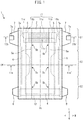
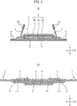
- Fig. 1 and Fig. 2 are diagrams showing an absorbent article 1 (disposable diaper), and specifically, Fig. 1 shows a plan view of the absorbent article 1 in the deployed, spread-out state, Fig. 2(a) is a cross-sectional view along line IIa-IIa' of Fig. 1 , and Fig. 2(b) is a cross-sectional view along line IIb-IIb' of Fig. 1 . However, Fig. 2(b) shows the absorbent article in the natural state, i.e., the state in which the expandable-and-shrinkable member 11 is shrunk, as described later.
- the absorbent article 1 has a lengthwise direction L, a widthwise direction W perpendicular to the lengthwise direction L, and a thickness direction T perpendicular to the lengthwise direction L and the widthwise direction W, and also has a center axis line CL extending through the center of the widthwise direction W and extending in the lengthwise direction L, and a center axis line CW extending through the center of the lengthwise direction L and extending in the widthwise direction W.
- the absorbent article 1 also has, in the lengthwise direction L, a back girth region S1 corresponding to the girth around the back side of the wearer, an abdominal girth region S2 corresponding to the girth around the abdominal side of the wearer, and a groin region S3 located between the back girth region S1 and the abdominal girth region S2, corresponding to the groin of the wearer. It is worn as a diaper by connecting both ends in the widthwise direction W of the back girth region S1 and both ends in the widthwise direction W of the abdominal girth region S2.
- the groin region S3 may be narrowed in the widthwise direction W.
- the simple phrase “as plane view” will be used to mean that the absorbent article 1 in the deployed spread-out flat state is viewed from the upper side in the thickness direction.
- the terms “skin side” and “non-skin side” refer, respectively, to the side relatively near the skin side and the side relatively away from the skin side of the wearer, in the thickness direction of the absorbent article, when the wearer of the absorbent article has worn the absorbent article.
- the direction toward the center axis line CL is the direction on the inner side in the widthwise direction W
- the direction receding from the center axis line CL is the direction on the outer side in the widthwise direction W.
- the direction toward the center axis line CW is the direction on the inner side in the lengthwise direction L
- the direction receding from the center axis line CW is the direction on the outer side in the lengthwise direction L.
- the absorbent article 1 comprises a front sheet 2, a back sheet 3 and an absorbent body 4.
- the lengthwise direction, widthwise direction and thickness direction of the front sheet 2, back sheet 3 and absorbent body 4 all match the lengthwise direction L, widthwise direction W and thickness direction T of the absorbent article 1.
- the lengthwise direction L, widthwise direction W and thickness direction T are each used for the lengthwise direction, widthwise direction and thickness direction for the front sheet 2, back sheet 3 and absorbent body 4 as well, and the skin side and non-skin side are respectively used for the side relatively near and the side relatively away from the skin side of the wearer, in the thickness direction.
- the front sheet 2 is a liquid-permeable sheet situated on the skin side of the wearer.
- the front sheet 2 may be any desired liquid-permeable sheet, such as, for example, a liquid-permeable nonwoven fabric or woven fabric, a liquid-permeable porous synthetic resin film, or a composite sheet thereof.
- the back sheet 3 is a liquid-impermeable sheet situated on the non-skin side of the wearer.
- the back sheet 3 may be any desired liquid-impermeable sheet, such as, for example, a liquid-impermeable nonwoven fabric or synthetic resin film, a composite sheet thereof, an SMS nonwoven fabric, or the like.
- the absorbent body 4 is a fluid-absorbing and liquid-retaining material situated between the front sheet 2 and the back sheet 3, and for this embodiment, it includes the absorbent body core 4a and core wraps 4b, 4c that subsume the absorbent body core 4a.
- the absorbent body 4 may be pulp fiber, synthetic fiber, an absorbing polymer or the like.
- the absorbent body 4 is bonded to each of the front sheet 2 and back sheet 3 with an adhesive, the front sheet 2 and back sheet 3 being bonded by an adhesive at their peripheries.
- the adhesive used for bonding between the front sheet 2, absorbent body 4 and back sheet 3 may be a known material that is commonly used in absorbent articles 1, such as a thermoplastic adhesive.
- the absorbent article 1 further comprises a pair of leak resistant walls 5, 5, leg expandable-and-shrinkable members 6, 6 and an outer sheet 9.
- the pair of leak resistant walls 5, 5 are a pair of side section sheets that extend along the lengthwise direction L so as to cover the surfaces of both sides in the widthwise direction W of the front sheet 2, and they are disposed across a distance in the widthwise direction W.
- the pair of leak resistant walls 5, 5 have their fixed ends at the edges on the outer sides in the widthwise direction W fixed on the surface of both sides in the widthwise direction W of the front sheet 2, and have their free ends forming gather sections that are expandable and shrinkable at the edges on the inner side in the widthwise direction W, also including folded rising sections 5c that are able to rise up in the thickness direction T.
- the pair of leak resistant walls 5, 5 each further include, at both ends in the lengthwise direction L of the rising section 5c, joint sections 5b extending in the lengthwise direction L, where the rising section 5c is connected to the front sheet 2.
- the leg expandable-and-shrinkable member 6 is an elastic material such as rubber that expands in the lengthwise direction L of each of both sides in the widthwise direction W of the groin region S3 that contacts with the femoral region of the wearer.
- the outer sheet 9 reinforces the back sheet 3 on the non-skin side of the back sheet 3, and improves its hand feel. It is mutually connected with the pair of leak resistant walls 5, 5 at the peripheral sections while being joined to the non-skin side of the back sheet 3.
- the materials for the leak resistant walls 5 and the outer sheet 9 include the material for the front sheet 2, for the leak resistant walls 5, and the material for the back sheet 3, for the outer sheet 9.
- the absorbent article 1 further comprises an expandable-and-shrinkable member 11 and a pair of protrusion sections 7 in the back girth region S1.
- the expandable-and-shrinkable member 11 is a sheet that is expandable and shrinkable in the expansion-and-shrink direction, and is disposed between the pair of protrusion sections 7, 7 so as to be along the expansion-and-shrink direction in the widthwise direction W, i.e., expandable and shrinkable in the widthwise direction W, functioning as a waist gather, for example.
- the expandable-and-shrinkable member 11 is attached using an adhesive to any location of the surface on the skin side of the front sheet 2, the surface on the non-skin side of the back sheet 3, and the region between the front sheet 2 and the back sheet 3, in the back girth region S1.
- the expandable-and-shrinkable member 11 is also disposed either partially overlapping or without any overlapping with the absorbent body 4, as plane view.
- the expandable-and-shrinkable member 11 is disposed between the front sheet 2 and the back sheet 3 in such a manner that the portion on the inner side in the lengthwise direction L of the expandable-and-shrinkable member 11 overlaps with the absorbent body 4 as plane view.
- the expandable-and-shrinkable member 11 also includes a high-expanded region 11a located at the center in the widthwise direction W and low-expanded regions 11b located at both sides in the widthwise direction W of the high-expanded region 11a.
- the high-expanded region 11a is attached to the front sheet 2 and/or back sheet 3 with the expandable-and-shrinkable member 11 in a widely expanded state, and it undergoes large shrink together with the front sheet 2 and/or back sheet 3 by returning to the natural state after having been expanded, whereby a plurality of wrinkles 11S are formed.
- the wrinkles 11S extend generally in the lengthwise direction L and are arranged generally in the widthwise direction W.
- the low-expanded regions 11b are attached to the front sheet 2 and/or back sheet 3 with the expandable-and-shrinkable member 11 in a modestly expanded state, and they shrink moderately together with the front sheet 2 and/or back sheet 3 by returning to the natural state after having been expanded, such that few wrinkles are formed.
- the high-expanded region 11a is a region capable of high expansion and shrink
- the low-expanded regions 11b are regions capable of low expansion and shrink.
- the low-expanded regions 11b are not essential, and the entirety may consist of the high-expanded region 11a.
- the material of the expandable-and-shrinkable member 11 is not particularly restricted so long as it is expandable and shrinkable, and it may be expandable and shrinkable as a material, or expandable and shrinkable in shape, or expandable and shrinkable by combination with an elastic member.
- the pair of protrusion sections 7, 7 are sheets for connection of the back girth region S1 to the abdominal girth region S2 during wear, and they function as side flaps.
- the pair of protrusion sections 7, 7 are disposed so as to protrude toward both outer sides in the widthwise direction W of the back girth region S1, and are attached with an adhesive at any location on the surface of the skin side of the front sheet 2 (or leak resistant wall 5), on the surface of the non-skin side of the back sheet 3 (or outer sheet 9), in the region between the front sheet 2 (or leak resistant wall 5) and the back sheet 3 (or outer sheet 9) in the back girth region S1.
- the pair of protrusion sections 7, 7 may also be formed at the extended sections of either or both the front sheet 2 (or leak resistant wall 5) and the back sheet 3 (or outer sheet 9).
- the protrusion sections 7 are disposed between the leak resistant wall 5 and the outer sheet 9, with separate members from the front sheet 2, leak resistant wall 5, back sheet 3 and outer sheet 9.
- the protrusion sections 7 comprise connecting tapes 7a for connection with a to-be-connected member 12 (described below) in the abdominal girth region S2 during wear.
- the connecting tapes 7a may be a hook-and-loop fastener or adhesive tape.
- the material for the protrusion sections 7 is not particularly restricted, and may be the material of the front sheet 2 or back sheet 3, for example.
- the expandable-and-shrinkable member 11 is disposed between the pair of protrusion sections 7, 7. That is, it is disposed in such a manner that the expandable-and-shrinkable member 11 and the pair of protrusion sections 7, 7 overlap in at least sections in the lengthwise direction L. Stated differently, projection onto the center axis line CL of the edge line 11e along the lengthwise direction L on the outer side in the widthwise direction W of the expandable-and-shrinkable member 11, and projection onto the center axis line CL of the edge line 7e along the lengthwise direction L on the inner side in the widthwise direction W of the protrusion section 7, overlap at least partially. This can improve the fitting property of the absorbent article 1 in the girth region during wear.
- the absorbent article 1 further comprises a to-be-connected member 12 and a pair of protrusion sections 8 in the abdominal girth region S2.
- the to-be-connected member 12 is a sheet that is to be connected with the connecting tapes 7a of the pair of protrusion sections 7, 7, and when the connecting tapes 7a are hooks of hook-and-loop fasteners, for example, the to-be-connected member 12 is a loop of a hook-and-loop fastener, and when the connecting tapes 7a are adhesive tapes, the to-be-connected member 12 is a sheet capable of pressure-sensitive adhesion with the adhesive tape.
- the to-be-connected member 12 is attached with an adhesive at a location on the surface on the non-skin side of the outer sheet 9 in the abdominal girth region S2.
- the to-be-connected member 12 is also disposed either partially overlapping or without any overlapping with the absorbent body 4, as plane view.
- the to-be-connected member 12 is disposed on the surface on the non-skin side of the outer sheet 9, in such a manner that a portion on the inner side in the lengthwise direction L of the to-be-connected member 12 overlaps with the absorbent body 4, as plane view.
- the pair of protrusion sections 8, 8 are sheets for connection of the back girth region S2 to the abdominal girth region S1 during wear, and they function as side flaps.
- the pair of protrusion sections 8 are disposed so as to protrude toward both outer sides in the widthwise direction W of the abdominal girth region S2, and are attached with an adhesive at any location on the surface of the skin side of the front sheet 2 (or leak resistant wall 5), on the surface of the non-skin side of the back sheet 3 (or outer sheet 9), and in the region between the front sheet 2 (or leak resistant wall 5) and the back sheet 3 (or outer sheet 9) in the abdominal girth region S2.
- the pair of protrusion sections 8, 8 may also be formed at the extended sections of either or both the front sheet 2 (or leak resistant wall 5) and the back sheet 3 (or outer sheet 9).
- the protrusion sections 8 are disposed between the leak resistant wall 5 and the outer sheet 9, with separate members from the front sheet 2, leak resistant wall 5, back sheet 3 and outer sheet 9.
- the material for the protrusion sections 8 is not particularly restricted, and may be the material of the front sheet 2 or back sheet 3, for example.
- the protrusion sections 8 may also be absent.
- FIG. 3 shows an example of a configuration of a production apparatus 200 for an absorbent article 1.
- the production apparatus 200 comprises a front sheet-forming unit 200A, an absorbent body-forming unit 200B, a back sheet-forming unit 200C, an expandable-and-shrinkable member-bonding unit 200D, a bonding unit 200E and a folding unit 200F.
- the production apparatus 200 For transport of the absorbent article 1 and the materials composing it, the production apparatus 200 has a machine direction MD, a cross-machine direction CD perpendicular to the machine direction MD along the transport surface, and a thickness direction TD perpendicular to the machine direction MD and the cross-machine direction CD.
- the lengthwise direction, widthwise direction and thickness direction of the absorbent article 1 and the materials composing it are the same as the machine direction MD, cross-machine direction CD and thickness direction TD, respectively.
- the machine direction MD, cross-machine direction CD and thickness direction TD are used as the lengthwise direction, widthwise direction and thickness direction, respectively.
- a plurality of transport rolls convey a continuous front sheet 102, as a continuous sheet for the front sheet, to a bonding roll 210.
- An adhesive coating applicator 201 coats the adhesive onto one side of the continuous front sheet 102 during transport.
- a plurality of transport rolls convey a pair of continuous leak resistant wall sheets 105, 105, as continuous sheets for the pairs of leak resistant walls, to the bonding roll 210.
- the bonding roll 210 compresses the continuous front sheet 102 and the pair of continuous leak resistant wall sheets 105, 105 sandwiched between the pair of bonding rolls that are disposed mutually facing each other, forming a continuous front sheet 102 with the pair of continuous leak resistant wall sheets 105, 105 bonded with an adhesive on both outer sides in the cross-machine direction.
- the adhesive coating applicator 202 coats the adhesive on the other side, which is the side of the transported continuous front sheet 102 opposite the side on which the continuous leak resistant wall sheets 105, 105 are bonded.
- a plurality of transport rolls supply the continuous front sheet 102 to the bonding unit 200E (bonding rolls 240, 250).
- the conveyor belt supplies an absorbent body 104 formed by an absorbent body-forming apparatus (not shown) to the bonding unit 200E (bonding rolls 240, 250).
- a plurality of transport rolls convey a continuous back sheet 103, as a continuous sheet for the back sheet, to a bonding roll 220.
- a plurality of transport rolls transport a continuous outer sheet 109 (with the leg expandable-and-shrinkable member 6, protrusion sections 7, 8 and to-be-connected member 12 already added) as a continuous sheet for the outer sheet, to the bonding roll 220.
- An adhesive coating applicator 203 coats an adhesive onto one side of the continuous outer sheet 109 during transport.
- the bonding roll 220 compresses the continuous outer sheet 109 and the continuous back sheet 103 sandwiched between the pair of bonding rolls that are disposed mutually facing each other, forming a continuous back sheet 103 with the continuous outer sheet 109 bonded on the back side.
- An adhesive coating applicator 204 coats the adhesive on the other side of the transported continuous back sheet 103 where the continuous outer sheet 109 is not bonded.
- a plurality of transport rolls supply the continuous back sheet 103 to the bonding unit 200E (bonding roll 240).
- a plurality of transport rolls transport a continuous expandable-and-shrinkable member sheet 111, which is a continuous sheet for the expandable-and-shrinkable members, to a cutting apparatus 230.
- the cutting apparatus 230 cuts the continuous expandable-and-shrinkable member sheet 111 into prescribed lengths with a cutter.
- a widening/attaching apparatus 400 receives the cut fragments, i.e., the expandable-and-shrinkable member 11, while holding both end sections of the expandable-and-shrinkable member in the cross-machine direction.
- the widening/attaching apparatus 400 expands the expandable-and-shrinkable member 11 in the cross-machine direction while rotating approximately 180°.
- the widening/attaching apparatus 400 presses the expandable-and-shrinkable member 11 in the expanded state against the side of the continuous back sheet 103 on which the adhesive was coated, which was on the bonding roll 240, to attach it to the continuous back sheet 103. Since the continuous back sheet 103 is under tension in the machine direction MD during this time, the continuous back sheet 103 undergoes virtually no narrowing even when the expandable-and-shrinkable member 11 in the extended expanded out state in the cross-machine direction CD is attached.
- the bonding roll 240 moves the continuous back sheet 103 onto which the expandable-and-shrinkable member 11 has been attached, to the bonding unit 200E (bonding roll 250).
- the pair of bonding rolls 240, 250 that are disposed mutually facing each other compress the continuous front sheet 102 from the front sheet-forming unit 200A, the absorbent body 104 from the absorbent body-forming unit 200B and the continuous back sheet 103 from the back sheet-forming unit 200C while sandwiching them, to form a semi-processed continuous body 101a of a semi-processed absorbent article having the continuous front sheet 102, the absorbent body 104 and the continuous back sheet 103 laminated.
- a plurality of transport rolls transport the semi-processed continuous body 101a away from the bonding roll 240, while reducing the tension in the machine direction MD.
- a plurality of transport rolls transport the semi-processed continuous body 101b to the folding unit 200F.
- a folding apparatus 300 transports the semi-processed continuous body 101b by a transport roll 303 and a conveying apparatus 310, while folding it with a pressing member 301 and a folding member 302, to form a semi-processed continuous body 101c.
- the semi-processed continuous body 101c is then cut into individual absorbent article product portions as the absorbent article 1.
- the widening/attaching apparatus 400 of the expandable-and-shrinkable member-bonding unit 200D will now be explained.
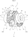
- Fig. 4 is a perspective view schematically showing an example of a configuration of the widening/attaching apparatus 400.
- the widening/attaching apparatus 400 is an apparatus that receives a belt-shaped width-shrunk member 405 at a receiving position P1 and expands it in the cross-machine direction CD while delivering it to the continuous back sheet 103 at a delivering position P2.
- the widening/attaching apparatus 400 comprises a pair of widening units 400A1, 400A2 having bilateral symmetry with respect to the center line CLA.
- Each widening unit 400A comprises a relative moving member 430, a transport driving member 420 and a pair of transporting members 410, 410.
- the pair of widening units 400A1, 400A2 are set in positions so as to be mutually close at one end and mutually far at the other end (they are divergent with respect to each other).
- the receiving position P1 is where they are mutually close and the delivering position P2 is where they are mutually far.
- the transport driving member 420 has a rotor 422 that rotates around a rotating shaft 421 as the center, the rotor 422 being mounted in a freely rotatable manner around the relative moving member 430 via a bearing.
- the pair of transporting members 410 are anchored at positions mutually separated 180° in the rotational direction of the rotor 422. Consequently, by rotation of the pair of transport driving members 420 at the same angular speed, rotation takes place around the relative moving member 430, with the transport members 410 facing each other on the rotors 422 of both widening units 400A1, 400A2.
- Each of the transport members 410 comprises a suction pad 411.
- the suction pad 411 is situated on the outer side surface of the transport member 410, and has a contact surface 411a with which the expandable-and-shrinkable member 11 contacts.
- a plurality of holes are formed in the contact surface 411a, some of the holes being suction holes 411c for suctioning of the expandable-and-shrinkable member 11 in contact with the contact surface 411a, by a suction mechanism (not shown) situated in the transport member 410, while the other holes are pinholes 411b through which pin members are inserted to anchor the expandable-and-shrinkable member 11 in contact with the contact surface 411a.
- the widening/attaching apparatus 400 receives the expandable-and-shrinkable member 11 by suctioning both end sections of the expandable-and-shrinkable member 11 by the suction holes 411c of the pair of transporting members 410.
- the pin members of the pinholes 411b pierce the expandable-and-shrinkable member 11, thereby holding the expandable-and-shrinkable member 11 by the pair of transporting members 410.
- the widening/attaching apparatus 400 rotationally moves the pair of transporting members 410 by the pair of transport driving members 420, causing the expandable-and-shrinkable member 11 to move from the receiving position P1 to the delivering position P2.
- the pair of transporting members 410 rotationally move while gradually widening the distance between the suction pads 411, such that both end sections of the expandable-and-shrinkable member 11 are pulled and expanded. Also, the widening/attaching apparatus 400 delivers the expandable-and-shrinkable member 11 by termination of the suction and pin piercing with the pair of transporting members 410 at the delivering position P2.
- the center section in the cross-machine direction CD of the expandable-and-shrinkable member 11 (for example, the portion on the inner side between the suction pads 411) can be the region with high expanding (high-expanded region) and the both end sections on both sides thereof (for example, the portions of the suction pads 411) can be the regions with low expanding (low-expanded regions), or the entire expandable-and-shrinkable member 11 can be the high-expanded region.
- Adjustment of the widening units 400A1, 400A2 may be, for example, adjustment of the distance between the widening units 400A1, 400A2, the degree of suction of the suction pads 411, or the presence or absence of insertion of the pin members in the pinholes 411b.
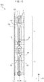
- the folding apparatus 300 of the folding unit 200F will now be explained.
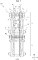
- Fig. 5 is a diagram schematically showing an example of a configuration of the folding apparatus 300.
- the folding apparatus 300 is an apparatus that folds a continuous body at a prescribed folding position while transporting the continuous body in the machine direction MD, and it comprises a transport roll 303, a conveying apparatus 310, a pressing member 301 and a folding member 302.
- the semi-processed continuous body 101b will be used as an example of the continuous body.
- the transport roll 303 supplies the semi-processed continuous body 101b to the pressing member 301 and the conveying apparatus 310, located downstream in the machine direction.
- the pressing member 301 is disposed on the conveying apparatus 310, downstream form the transport roll 303 in the machine direction MD.
- the length of the pressing member 301 is set to be narrower than the length of the semi-processed continuous body 101b.
- the pressing member 301 presses at least the center region of the semi-processed continuous body 101b toward the direction crossing the surface of the semi-processed continuous body 101b, or in other words, toward the surface of the conveying apparatus 310 on which the semi-processed continuous body 101b is mounted, while transporting the semi-processed continuous body 101b in the machine direction.
- the conveying apparatus 310 rotates an endless belt 310b in the machine direction MD by a roller 310a or a roller 310c, transporting the semi-processed continuous body 101b in the machine direction MD.
- a suction mechanism is mounted in the conveying apparatus 310, and the center region of the semi-processed continuous body 101b is pressed toward the endless belt 310b by the pressing member 301, while being suctioned to the transport surface of the endless belt 310b (the mounting surface of the semi-processed continuous body 101b).
- the folding member 302 guides the side section regions on both sides in the cross-machine direction CD of the semi-processed continuous body 101b that is being transported along the machine direction MD, onto the center region, by guides 302a, 302a.
- the suction mechanism does not need to be mounted on the conveying apparatus 310.
- the pressing member 301 has a pair of presser rolls 301b, 301b that press the semi-processed continuous body 101b, and a center roll 301a that is disposed between the presser rolls 301b, 301b and presses the center region of the semi-processed continuous body 101b.
- the position of the semi-processed continuous body 101b pressed by the presser rolls 301b, 301b becomes the folding origin, and the line drawn along the machine direction MD at that position becomes the folding line.
- the presser rolls 301b, 301b can be moved to any desired position between both ends and the center of the semi-processed continuous body 101b in the cross-machine direction CD.
- the folding line can be set with the folding apparatus 300 along the machine direction MD, at any desired position in the cross-machine direction CD.
- the presser rolls 301b, 301b may even be absent, in which case the function of the presser rolls 301b, 301b is carried out by both ends of the center roll 301a in the cross-machine direction CD.
- the transport roll 303 is disposed at a position of height h higher than the transport surface of the endless belt 310b, the width of the pressing member 301 being smaller than the width of the semi-processed continuous body 101b.
- This causes upward turning force to act from the transport surface of the endless belt 310b onto the pressing member 301 sides, in the side section regions of the semi-processed continuous body 101b that are not pressed against the pressing member 301.
- the upwardly turned side section regions are guided by the guides 302a, 302a, and fall back onto the center region. This allows folding of the side section regions (the regions connected in the machine direction MD).
- the width (length) of the pressing member 301 in the cross-machine direction CD is set to be narrower than the width (length) of the semi-processed continuous body 101b and narrower than the width (length) of the expandable-and-shrinkable member 11. It is preferably set to be narrower than the width (length) of the high-expanded region 11a of the expandable-and-shrinkable member 11. This allows the semi-processed continuous body 101b to be easily folded, as described below.
- the semi-processed continuous body 101b is folded in the folding apparatus 300 as a semi-processed continuous body 101c.
- the semi-processed continuous body 101c is then cut into individual absorbent article product portions as the absorbent article 1.
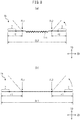
- Fig. 6 to Fig. 11 schematically show an example of the configuration of a semi-processed product, for explanation of the method for producing an absorbent article.
- the product runs from top to bottom in the drawing, in the machine direction MD.
- the production method is a method for producing an absorbent article, and it comprises a front sheet-forming step, an absorbent body-forming step, a back sheet-forming step, an expandable-and-shrinkable member bonding step, a bonding step (the above steps being the providing step), a shrinking step, a pressing step and a folding step.
- a continuous front sheet 102 which is the continuous sheet for the front sheet is coated with an adhesive on one side by the adhesive coating applicator 201, and then supplied to the bonding roll 210.
- a pair of continuous leak resistant wall sheets 105, 105 as continuous sheets for the pairs of leak resistant walls are supplied to the bonding roll 210.
- the continuous front sheet 102 and the pair of continuous leak resistant wall sheets 105, 105 are supplied between the pair of bonding rolls.
- the pair of continuous leak resistant wall sheets 105, 105 are pressed against the side of the continuous front sheet 102 on which the adhesive has been coated, thereby forming a continuous front sheet 102 having the pair of continuous leak resistant wall sheets 105, 105 bonded to both outer sides in the cross-machine direction.
- the adhesive coating applicator 202 the continuous front sheet 102 is coated with an adhesive on the other side which is the side opposite the side on which the continuous leak resistant wall sheets 105, 105 have been bonded, and then supplied to the bonding unit 200E (bonding rolls 240, 250).
- an absorbent body 104 is formed at an absorbent body-forming apparatus (not shown), and supplied to the bonding unit 200E (bonding rolls 240, 250) by a conveyor belt.
- a continuous back sheet 103 which is the continuous sheet for the back sheet is supplied to the bonding roll 220.
- a continuous outer sheet 109 (with the leg expandable-and-shrinkable member 6, protrusion sections 7, 8 and to-be-connected member 12 added), which is the continuous sheet for the outer sheet, is coated with an adhesive on one side by the adhesive coating applicator 203, and supplied to the bonding roll 220.
- the continuous outer sheet 109 and the continuous back sheet 103 are supplied between a pair of bonding rolls.
- the continuous back sheet 103 is pressed against the side of the continuous outer sheet 109 on which the adhesive has been coated to attach them both, thereby forming a continuous back sheet 103 in which the continuous outer sheet 109 is bonded to the back side.
- the adhesive coating applicator 204 the continuous back sheet 103 is coated with an adhesive on the other side on which the continuous outer sheet 109 is not bonded, and then supplied to the bonding unit 200E (bonding roll 240) .
- a continuous expandable-and-shrinkable member sheet 111 which is the continuous sheet for the expandable-and-shrinkable members, is supplied to the cutting apparatus 230, and the tip sections in the machine direction MD are cut to a prescribed length by the cutter of the cutting apparatus 230.
- Each cut fragment, i.e., the expandable-and-shrinkable member 11 is held at the both end sections in the cross-machine direction CD by the widening/attaching apparatus 400, and received by the widening/attaching apparatus 400.
- the expandable-and-shrinkable member 11 is rotated approximately 180° while the both end sections in the cross-machine direction CD are expanded in the cross-machine direction by the widening/attaching apparatus 400, and is then pressed against the adhesive-coated surface of the continuous back sheet 103 on the bonding roll 240 in the expanded state, and is attached to the continuous back sheet 103. Since the continuous back sheet 103 is under tension in the machine direction during this time, the continuous back sheet 103 undergoes virtually no narrowing even when the expandable-and-shrinkable member 11 in the extended expanded out state in the cross-machine direction CD is attached. The continuous back sheet 103 onto which the expandable-and-shrinkable member 11 has been attached moves over the bonding roll 240 to the bonding unit 200E (bonding roll 250).
- the continuous front sheet 102 on which the continuous leak resistant wall sheets 105, 105 are bonded from the front sheet-forming step, the absorbent body 104 from the absorbent body-forming step, and the continuous back sheet 103 on which the expandable-and-shrinkable member 11 is attached from the expandable-and-shrinkable member bonding step, are transported between the pair of bonding rolls 240, 250. Also, the continuous front sheet 102, the absorbent body 104 and the continuous back sheet 103 are sandwiched, compressed and bonded between the pair of bonding rolls 240, 250.
- a semi-processed continuous body 101a of the absorbent article is thus formed comprising the continuous front sheet 102, the continuous back sheet 103, and the absorbent body 104 lying between the continuous front sheet 102 and the continuous back sheet 103.
- the front sheet-forming step, absorbent body-forming step, back sheet-forming step, expandable-and-shrinkable member bonding step and bonding step may be considered as an example of the providing step for providing the semi-processed continuous body 101a.
- the providing step is not limited to this example, and for example, it may be a step of providing a pre-formed semi-processed continuous body 101a.
- Fig. 6 schematically shows an example of the structure of a semi-processed continuous body 101a.
- the semi-processed continuous body 101a is composed of a plurality of semi-processed products 1a connected in the machine direction.
- One semi-processed product 1a has virtually no wrinkles 11S in the expandable-and-shrinkable member 11, and has the same configuration as the absorbent article 1 shown in Fig. 1 .
- the semi-processed product 1a comprises a pair of protrusion sections 7, 7 formed protruding outward at both ends in the widthwise direction of the semi-processed product 1a, i.e., the cross-machine direction CD, and an expandable-and-shrinkable member 11 that is expandable and shrinkable in the expansion-and-shrink direction and is disposed in an expanded state between the pair of protrusion sections 7, 7 so that the expansion-and-shrink direction lies along the cross-machine direction CD.
- the expandable-and-shrinkable member 11 and protrusion section 7 are at least partially overlapping.
- the expandable-and-shrinkable member 11 and the protrusion sections 7 may be partially overlapping, or they may be non-overlapping.
- the maximum length at the portion including the expandable-and-shrinkable member 11 of the semi-processed product 1a (including the lengths of the protruding sections of the pair of protrusion sections 7, 7) is DL1.
- the expandable-and-shrinkable member 11 of the semi-processed product 1a undergoes virtually no shrink by tension on the semi-processed continuous body 101a.
- the expandable-and-shrinkable member 11 is disposed in the expanded state in the cross-machine direction CD, but is only slightly shrunk.
- the semi-processed continuous body 101a separates from the bonding roll 240 and tension in the machine direction MD is reduced (for example, the rotational speed of the transport roll is reduced). This allows the expandable-and-shrinkable member 11 expanded in the cross-machine direction CD to shrink, thereby allowing the expandable-and-shrinkable member 11 to be shrunk in the cross-machine direction CD.
- the portion including the expandable-and-shrinkable member 11 of the semi-processed product 1a can also be shrunk in the cross-machine direction CD, whereby a semi-processed continuous body 101b is formed in which the portion including the expandable-and-shrinkable member 11 is shrunk in the cross-machine direction CD.
- the shrinking step may also be included in the providing step.
- Fig. 7 schematically shows an example of the structure of a semi-processed continuous body 101b.
- the semi-processed continuous body 101b is composed of a plurality of semi-processed products 1b connected in the machine direction.
- One semi-processed product 1b has basically the same structure as the semi-processed product 1a shown in Fig. 6 .
- the portions including the expandable-and-shrinkable member 11 of the semi-processed product 1b are shrunk in the cross-machine direction CD (widthwise direction).
- the reduced tension on the semi-processed continuous body 101a causes the expandable-and-shrinkable member 11 disposed in an expanded state in the cross-machine direction CD, to be shrunk in the cross-machine direction CD of the semi-processed product 1b.
- the maximum length in the cross-machine direction CD (including the length of the protruding sections of the pair of protrusion sections 7, 7) DL2 is smaller than the length DL1 before shrink of the expandable-and-shrinkable member 11 ( Fig. 6 ) (DL2 ⁇ DL1).
- a plurality of wrinkles 11S are formed at the portions of the semi-processed continuous body 101b including the expandable-and-shrinkable member 11.
- the semi-processed continuous body 101b is transported by the folding unit 200F.
- the semi-processed continuous body 101b with the expandable-and-shrinkable member 11 shrunk is transported in the machine direction MD, while a center region MA of the semi-processed product 1b in the cross-machine direction CD is pressed in the direction toward the mounting surface of the semi-processed product 1b (the transport surface of the endless belt 310b), with the pressing member 301 whose length in the cross-machine direction CD is smaller than the length of the expandable-and-shrinkable member 11 in the cross-machine direction CD.
- the region of the expandable-and-shrinkable member 11 with a plurality of wrinkles 11S becomes pressed.
- the semi-processed continuous body 101b is transported in the machine direction MD while a pair of side section regions PA, PA on the outer sides of the center region MA of the semi-processed product 1b in the cross-machine direction CD are raised in the direction opposite from the direction toward the mounting surface of the semi-processed product 1b by the folding member 302 (guides 302a, 302a) on a pair of folding lines FL1, FL2 extending along the machine direction MD, and each is folded upward above the center region MA.
- a semi-processed continuous body 101c is thus formed.
- the pair of folding lines FL1, FL2 is set so as to extend along the machine direction MD, to the inner side from both edge lines 11e, 11e of the expandable-and-shrinkable member 11 in the cross-machine direction CD. They are preferably set so as to extend along the machine direction MD, to the inner side from the edge lines 7e, 7e on the inner side in the cross-machine direction CD of the pair of protrusion sections 7, 7.
- the pressing step and the folding step may be carried out in a temporally overlapping manner, or the folding step may be carried out after the pressing step.
- the semi-processed product 1b has the pair of protrusion sections 7, 7 that are discontinuous in the machine direction MD, formed so as to protrude to the outer sides at both ends in the cross-machine direction CD (widthwise direction), and at the folding apparatus 300, the discontinuous pair of protrusion sections 7, 7 can potentially be difficult to fold in a stable manner.
- having the configuration described above using the expandable-and-shrinkable member 11 allows the pair of protrusion sections 7, 7 to be stably folded. The reason for this is as follows.
- Fig. 8 is a schematic diagram illustrating a method of folding the semi-processed product 1b.
- Fig. 8(a) shows a case having the expandable-and-shrinkable member 11 where the expandable-and-shrinkable member 11 is shrunk, i.e., a case of the present embodiment.
- Fig. 8(b) shows a case not having the expandable-and-shrinkable member 11, i.e., a case that is not the present embodiment.
- the expandable-and-shrinkable member 11 is not present, i.e., in the case that is not the present embodiment ( Fig.
- the length in the cross-machine direction CD (widthwise direction) of the semi-processed product 1b is a relatively large value of DL1, while the lengths of the portions on the outer sides from the folding lines FL1, FL2 are also relatively large values of r1.
- moments of inertia around the folding lines FL1, FL2, of the portions (including the protrusion sections 7, 7) that are more toward the outer sides than the folding lines FL1, FL2, become relatively large values.
- the expandable-and-shrinkable member 11 is present and shrunk, i.e., in the case of the present embodiment ( Fig.
- the function of the expandable-and-shrinkable member 11 causes the length in the cross-machine direction CD (widthwise direction) of the portion including the expandable-and-shrinkable member 11 of the semi-processed product 1b to be a relatively small value of DL2 ( ⁇ DL1), while the lengths of the portions on the outer sides from the folding lines FL1, FL2 are also relatively small values of r2 ( ⁇ r1).
- DL2 cross-machine direction
- r2 ⁇ r1
- the force necessary to rotate the portions (including the protrusion sections) that are more toward the outer sides than the folding lines FL1, FL2, around the folding lines FL1, FL2 as the centers of rotation, i.e., the force necessary to raise them, can be reduced.
- the discontinuous protrusion sections 7, 7 can be easily raised.
- Fig. 9 is a schematic diagram illustrating a method of folding the semi-processed product 1b.
- Fig. 9(a) and Fig. 9(b) show the state of the portion including the expandable-and-shrinkable member 11 of the semi-processed product 1b before and after pressing by the pressing member 301, respectively.
- the tops of the wrinkles 11S that have convex shapes toward the side opposite the mounting surface side are pressed against the mounting surface side, and the wrinkles 11S are expanded, and thus the pressed regions spread out in the cross-machine direction CD on the mounting surface side.
- the non-pressed regions i.e., the side section regions PA further on the outer sides in the cross-machine direction CD than the pressed regions, instead rise up in the direction opposite the direction toward the mounting surface. Consequently, the portion including the expandable-and-shrinkable member 11 of the semi-processed product 1b has, throughout, concave shapes formed on the side opposite the mounting surface.
- the protrusion sections 7, 7 disposed on both sides in the cross-machine direction CD of the side section regions PA also easily tend to rise to follow the concave shapes.
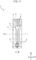
- Fig. 10 schematically shows an example of the structure of a semi-processed continuous body 101c.
- the semi-processed continuous body 101c is composed of a plurality of semi-processed products 1c connected in the machine direction.
- One semi-processed product 1c has basically the same structure as the semi-processed product 1b shown in Fig. 7 .
- the pair of side section regions PA, PA of the semi-processed product 1c are each folded upward over the center region MA.
- the semi-processed continuous body 101c is further cut into individual absorbent article product portions as the absorbent article 1.
- Fig. 11 schematically shows an example of the structure of an absorbent article 1 cut into a product portion.
- the cut absorbent article 1 has the same structure as the semi-processed product 1c of Fig. 8 .
- the absorbent article 1 is folded in the machine direction MD at a folding line FL3 that extends through the center section in the machine direction MD and extends along the cross-machine direction CD.
- the absorbent article is produced in this manner.
- the entire expandable-and-shrinkable member 11 overlaps with the pair of protrusion sections 7, 7 in the machine direction MD. It is thus possible to more powerfully exhibit the effect of mounting the expandable-and-shrinkable member 11 (the effect of lowering the moment of inertia of the portions including the protrusion sections around the folding lines FL1, FL2 and the effect of forming the expandable-and-shrinkable member 11 into a concave shape by pressing of the wrinkles 11S).
- the protrusion sections can thus be more stably folded together with the side section regions.
- the folding lines FL1, FL2 overlap the regions where the rising sections 5c of the leak resistant walls 5 are overlapping and the rigidity is increased.
- it can aid in rising of the side section regions PA, PA due to the shrink of the rising sections 5c in the machine direction MD. This allows the protrusion sections to be more stably folded together with the side section regions.
- the rising sections 5c of the leak resistant walls 5 do not overlap the expandable-and-shrinkable member 11 in the machine direction MD.
- expansion-and-shrink of the expandable-and-shrinkable member 11 in the cross-machine direction CD is not affected by expansion of the rising sections 5c in the machine direction MD.
- This allows suitable shrink of the expandable-and-shrinkable member 11, and allows the effect of mounting the expandable-and-shrinkable member 11 to be more strongly exhibited.
- the protrusion sections can thus be more stably folded together with the side section regions.
- the folding lines FL1, FL2 overlap the regions where the joint sections 5b of the leak resistant walls 5 overlap and the rigidity is increased. This allows the rigidity to be increased at the creases by the folding lines FL1, FL2, to allow the creases to be stabilized.
- the protrusion sections can thus be more stably folded together with the side section regions.
- the folding lines FL1, FL2 overlap the regions where the to-be-connected member 12 overlaps and the rigidity is increased. This allows the rigidity to be increased at the creases by the folding lines FL1, FL2, to allow the creases to be stabilized. The protrusion sections can thus be more stably folded together with the side section regions.
- the folding lines FL1, FL2 overlap the regions where the absorbent body 4 overlaps and the rigidity is increased. This allows the rigidity to be increased at the creases by the folding lines FL1, FL2, to allow the creases to be stabilized. The protrusion sections can thus be more stably folded together with the side section regions.
- the folding lines FL1, FL2 may be present in the region of the wrinkles 11S of the expandable-and-shrinkable member 11.
- the side section regions PA, PA can be easily folded with the wrinkles 11S as the origin, whereby the protrusion sections can be more stably folded together with the side section regions.
- the expandable-and-shrinkable member 11 and the protrusion sections 7, 7 may be overlapping. This allows the rigidity to be increased in the portions from the expandable-and-shrinkable member 11 to the protrusion sections 7, 7. The protrusion sections can thus be more stably folded together with the side section regions.
Landscapes
- Health & Medical Sciences (AREA)
- Engineering & Computer Science (AREA)
- Life Sciences & Earth Sciences (AREA)
- Biomedical Technology (AREA)
- Heart & Thoracic Surgery (AREA)
- Vascular Medicine (AREA)
- Epidemiology (AREA)
- Animal Behavior & Ethology (AREA)
- General Health & Medical Sciences (AREA)
- Public Health (AREA)
- Veterinary Medicine (AREA)
- Manufacturing & Machinery (AREA)
- Mechanical Engineering (AREA)
- Absorbent Articles And Supports Therefor (AREA)
Description
- The present invention relates to method for producing an absorbent article.
- Absorbent articles such as disposable diapers are known. When such an absorbent article is produced, a folding step is carried out in which the absorbent article is folded for packaging of the absorbent article. In the folding step, a semi-processed continuous body, that is composed of semi-processed products for the absorbent article connected in the machine direction, is transported in the machine direction while both ends of the semi-processed product in the widthwise direction are folded from the outside to the inside. That is, side section regions on both outer sides of the center region in the widthwise direction of the semi-processed product are folded so as to overlap in the center region.
- The folding method includes, for example, a method by a folding apparatus disclosed in
JP2011-50478 WO2010/092935 , for example, as a method for producing a disposable wearable article. This method for producing a disposable wearable article comprises a first folding step in which a waist section is folded so that the non-skin side of the waist section overlaps with the non-skin side of side flaps during the transport step, and a second folding step in which the side flaps are folded in such a manner that skin sides of the side flaps overlap with skin sides of a back section or a front section after the first folding step during the transport step. - Further prior art arrangements are known from
US2015/032075 andEP2474494 . - In some absorbent articles, a pair of protrusion sections (for example, back side flaps) are disposed protruding toward the outer side in the widthwise direction at both ends in the widthwise direction of the absorbent article. For production of such an absorbent article, in the above-mentioned folding step, there is supplied a semi-processed continuous body having a pair of protrusion sections that are not continuous in the machine direction, i.e., discontinuous, at each outer edge of a pair of side section regions connected in the machine direction.
- When such a semi-processed continuous body is folded using the folding apparatus of
Patent Literature 1, the side section regions that are continuous in the machine direction are easily folded so as to overlap the center region, but each of the protrusion sections that are not connected in the machine direction, i.e., that are discontinuous, is difficult to fold in a manner overlapping the center region. This is because the folding apparatus ofPatent Literature 1 is designed for a product in which the side section regions to be folded are continuous in the lengthwise direction, and not for a structure having discontinuous portions (protrusion sections) in the side section regions. For example, focusing on specific sections in the side section regions that are continuous in the machine direction, other sections that are adjacent to those specific sections in the machine direction and are folded first facilitate the folding operation of those specific sections, so that the specific sections are easily folded in a manner overlapping the center region. However, since the adjacent protrusion sections in the machine direction are disposed in a mutually separated manner, that is, since the protrusion sections are disposed in a discontinuous manner, the leading protrusion sections do not facilitate the folding operation for the trailing protrusion sections. Consequently, when the side section regions are folded toward the center region so as to overlap the center region, the protrusion sections may or may not be able to follow the operation, and the manner of folding can potentially be unstable. In other words, with the folding apparatus described inPatent Literature 1, when the side section regions are folded, it can potentially be difficult to stably fold the protrusion sections. When this occurs, and the folded portions are opened during use, a condition is created in which the opening method differs for each product, confusing the user or requiring more time for fitting, and this may create a burden for the user. - In addition, when such a semi-processed continuous body is folded, using the method for producing a disposable wearable article of
Patent Literature 2, the protrusion sections are folded in the first folding step and the side section regions are folded in the second folding step, which allows the aforementioned problem of stable folding to be solved. However, because two locations are folded at each side in the widthwise direction of the semi-processed product, the amount of preliminary manipulation during use increases and the time to fitting is increased, when the folded portions are to be opened during use of the absorbent article, thereby potentially increasing the burden of operation for the user. - It is an object of the invention is to provide a method for producing an absorbent article that allows the protrusion sections to be stably folded together with the side section regions, without increasing the burden of operation during use.
- A method for producing an absorbent article according to the present invention is as follows.
- (1) A method for producing an absorbent article, comprising: a providing step of providing a semi-processed continuous body comprising semi-processed products for the absorbent article connected in a machine direction, the semi-processed product comprising a pair of protrusion sections formed protruding outward at both ends in the widthwise direction of the semi-processed product, and an expandable-and-shrinkable member that is expandable and shrinkable in an expansion-and-shrink direction and is disposed in an expanded state between the pair of protrusion sections so that the expansion-and-shrink direction is along the widthwise direction, a shrinking step of shrinking the expandable-and-shrinkable member to reduce a length in the widthwise direction at a portion including the expandable-and-shrinkable member in the semi-processed product to a length shorter than that before the shrinking, and form a plurality of wrinkles in the expandable-and-shrinkable member, a pressing step of pressing a center region in the widthwise direction of the semi-processed product, while transporting the semi-processed continuous body with the expandable-and-shrinkable member shrunk in the machine direction, and a folding step of raising, in a direction opposite from a direction of the pressing, a pair of side section regions on both outer sides in the widthwise direction of the center region of the semi-processed product at a pair of folding lines extending along the machine direction set more toward an inner side than both end sections in the widthwise direction of the expandable-and-shrinkable member, and folding each of the pair of side section regions upward above the center region, while transporting the semi-processed continuous body in the machine direction.
- In this method for producing an absorbent article, the structure employs an expandable-and-shrinkable member (for example, a waist gather), to allow stable folding of the protrusion sections together with the side section regions, without increasing the burden of operation during use. In other words, since a plurality of wrinkles are formed in the region where the expandable-and-shrinkable member is disposed due to the function of the expandable-and-shrinkable member, at least some of the plurality of wrinkles are collapsed by the pressing member when the center region of the semi-processed product is pressed in the direction toward a mounting surface of the semi-processed product, due to the pressing member having a smaller length in the widthwise direction than the expandable-and-shrinkable member. As a result, the tops of the wrinkles that have convex shapes toward the side opposite the mounting surface side are pressed against the mounting surface side, and when the wrinkles are expanded, the pressed regions spread out in the widthwise direction on the mounting surface side. As the pressed regions spread out in the widthwise direction on the mounting surface side, the non-pressed regions, i.e., the regions further on the outer side in the widthwise direction than the pressed regions, instead rise up in the direction opposite the direction toward the mounting surface. Consequently, the portion of the semi-processed product including the expandable-and-shrinkable member has, throughout, concave shapes formed on the side opposite the mounting surface. As a result, the protrusion sections disposed on both sides in the widthwise direction of the side section regions also easily rise to follow the concave shapes. Furthermore, due to the function of the expandable-and-shrinkable member, the length in the widthwise direction at the portion of the semi-processed product including the expandable-and-shrinkable member becomes smaller than before shrink, or in other words, it becomes smaller than the length in the widthwise direction at the portion of the semi-processed product that does not include the expandable-and-shrinkable member, and therefore the protrusion sections approach the inner side in the widthwise direction of the absorbent article such that the protrusion sections approach the folding line. Consequently, the moment of inertia of the protrusion sections around the folding lines is reduced. This reduces the force necessary to rotate the protrusion sections with the folding lines as the center of rotation, or in other words, it reduces the force necessary to raise the protrusion sections. As a result it is possible for the protrusion sections to be easily raised. In this method for producing an absorbent article, by provision of the expandable-and-shrinkable member in the absorbent article (semi-processed product), at least the two functions described above act synergistically to allow the protrusion sections to be easily raised, thereby allowing the protrusion sections to be stably folded together with the side section regions. In this case, the portions that have been folded need only be opened at one location on each side during use of the absorbent article, and therefore the burden of operation for the user is not increased. In other words, it is possible to stably fold the protrusion sections together with the side section regions without increasing the burden of operation during use.
- The method for producing an absorbent article according to the present invention may also be (2) the method for producing an absorbent article according to the above (1) wherein the folding lines are set so as to extend through the regions with the plurality of wrinkles.
- By this method for producing an absorbent article, it is possible to easily fold the side section regions with the wrinkles as origins, in the folding step. This allows the protrusion sections on the outer sides in the widthwise direction of the side section regions to be stably raised and the protrusion sections to be more stably folded together with the side section regions.
- The method for producing an absorbent article according to the present invention may also be (3) the method for producing an absorbent article according to the above (1) or (2) wherein the entire expandable-and-shrinkable member overlaps with the pair of protrusion sections in the machine direction.
- By this method for producing an absorbent article, it is possible to more powerfully exhibit the effect of mounting the expandable-and-shrinkable member, or in other words, the effect of forming a concave shape in the expandable-and-shrinkable member by pressing of the wrinkles and the effect of lowering the moment of inertia of the protrusion sections around the folding lines.
This allows the protrusion sections on the outer sides in the widthwise direction of the side section regions to be stably raised and the protrusion sections to be more stably folded together with the side section regions. - The method for producing an absorbent article according to the present invention may also be (4) the method for producing an absorbent article according to any one of the above (1) to (3), wherein the semi-processed product comprises a pair of leak resistant walls extending along the machine direction and disposed separately in the widthwise direction, the leak resistant walls include rising sections which are folded so as to be capable of rising in a thickness direction of the semi-processed product, and in which edges on inner sides in the widthwise direction are free ends so as to be expandable and shrinkable and edges on outer sides in the widthwise direction are fixed ends, and the folding lines are set so as to extend through the rising sections.
- Using this method for producing an absorbent article, it is possible to relatively increase the rigidity at the creases because the regions where the rising sections have been overlapped to have relatively higher rigidity overlap the folding lines. In other words, it can stabilize the creases. This allows the side section regions to be stably raised by the creases. In addition, it can aid in rising of the side section regions due to the shrink of the rising sections in the machine direction. This allows the protrusion sections on the outer sides in the widthwise direction of the side section regions to be more stably raised and the protrusion sections to be more stably folded together with the side section regions, in the same form.
- The method for producing an absorbent article according to the present invention may also be (5) the method for producing an absorbent article according to the above (4), wherein the rising sections do not overlap the expandable-and-shrinkable member in the machine direction.
- By this method for producing an absorbent article, expansion and shrink of the expandable-and-shrinkable member in the widthwise direction is not affected by expansion and shrink of the rising section in the machine direction. This allows the expandable-and-shrinkable member to be appropriately shrunk to form a plurality of wrinkles. Thus, it is possible to more powerfully exhibit the effect of mounting the expandable-and-shrinkable member, or in other words, the effect of forming a concave shape in the region of the semi-processed product including the expandable-and-shrinkable member and the effect of lowering the moment of inertia of the protrusion sections around the folding lines.
This allows the protrusion sections on the outer sides in the widthwise direction of the side section regions to be more stably raised and the protrusion sections to be more stably folded together with the side section regions. - The method for producing an absorbent article according to the present invention may also be (6) the method for producing an absorbent article according to the above (4) or (5), wherein the leak resistant walls comprise joint sections extending in the machine direction, connecting the rising sections to the semi-processed product at both ends in the machine direction of the rising sections, and the folding lines are set so as to extend through the joint sections.
- Using this method for producing an absorbent article, it is possible to relatively increase the rigidity at the creases because the regions where the joint sections have been overlapped to have relatively higher rigidity overlap the folding lines. In other words, it can stabilize the creases. This allows the side section regions to be stably raised at the creases, and allows the protrusion sections on the outer sides in the widthwise direction of the side section regions to be more stably raised and the protrusion sections to be more stably folded together with the side section regions.
- The method for producing an absorbent article according to the present invention may also be (7) the method for producing an absorbent article according to any one of the above (1) to (6), wherein the semi-processed product further comprises: another pair of protrusion sections disposed at both ends in the widthwise direction protruding toward the outer sides in the widthwise direction, and a to-be-connected member disposed between the other pair of protrusion sections, that is a member to which the pair of protrusion sections are joined during use of the absorbent article, and the folding lines are set so as to extend through the to-be-connected members.
- Using this method for producing an absorbent article, it is possible to relatively increase the rigidity at the creases because the regions where the to-be-connected members have been overlapped to have relatively higher rigidity overlap the folding lines. In other words, it can stabilize the creases. This allows the other side section regions to be stably raised at the creases, and allows the other protrusion sections on the outer sides in the widthwise direction of the other side section regions to also be stably raised and the other protrusion sections to be more stably folded together with the side section regions.
- The method for producing an absorbent article according to the present invention may also be (8) the method for producing an absorbent article according to any one of the above (1) to (7), wherein inner side edges of the pair of protrusion sections in the widthwise direction and outer side edges of the expandable-and-shrinkable member in the widthwise direction are mutually overlapping.
- In this method for producing an absorbent article, the rigidity at the portions from the expandable-and-shrinkable member to the protrusion sections is relatively increased. Thus, with rising of the side section regions, the protrusion sections on the outer sides in the widthwise direction of the side section regions can be stably raised and the protrusion sections can be more stably folded together with the side section regions.
- The method for producing an absorbent article according to the present invention may also be (9) the method for producing an absorbent article according to any one of the above (1) to (8), wherein the semi-processed product further comprises: an absorbent body disposed extending through a center in the widthwise direction and along the machine direction, and the folding lines are set so as to extend through edges in the widthwise direction of the absorbent body.
- Using this method for producing an absorbent article, it is possible to relatively increase the rigidity at the creases because the regions where the absorbent body in the semi-processed product has been overlapped to have relatively higher rigidity overlaps the folding lines. In other words, it can stabilize the creases. This allows the side section regions to be stably raised at the creases, and allows the protrusion sections disposed on the outer sides in the widthwise direction of the side section regions to be stably raised so that the protrusion sections can be more stably folded together with the side section regions.
- The present invention can provide a method for producing an absorbent article that allows the protrusion sections to be stably folded together with the side section regions, without increasing the burden of operation during use.
-
-
Fig. 1 is a diagram showing an absorbent article according to an embodiment. -
Fig. 2 is a diagram showing an absorbent article according to the embodiment. -
Fig. 3 is a schematic overview of a production apparatus for an absorbent article according to the embodiment. -
Fig. 4 is a schematic overview of a widening mechanism for an absorbent article according to the embodiment. -
Fig. 5 is a schematic overview of a folding apparatus for an absorbent article according to the embodiment. -
Fig. 6 is a diagram illustrating a method for producing an absorbent article according to the embodiment. -
Fig. 7 is a diagram illustrating a method for producing an absorbent article according to the embodiment. -
Fig. 8 is a diagram illustrating a method of folding an absorbent article according to the embodiment. -
Fig. 9 is a diagram illustrating a method of folding an absorbent article according to the embodiment. -
Fig. 10 is a diagram illustrating a method for producing an absorbent article according to the embodiment. -
Fig. 11 is a diagram illustrating a method for producing an absorbent article according to the embodiment. - An absorbent article according to the embodiment will now be explained with reference to the attached drawings, using a tape-type (open-type) disposable diaper as an example. However, the types and uses of the absorbent article of the present invention are not limited to this example, and the present invention may be applied to other absorbent articles such as panty-type disposable diapers, for example, without departing from the scope of the subject matter of the present invention.
-
Fig. 1 andFig. 2 are diagrams showing an absorbent article 1 (disposable diaper), and specifically,Fig. 1 shows a plan view of theabsorbent article 1 in the deployed, spread-out state,Fig. 2(a) is a cross-sectional view along line IIa-IIa' ofFig. 1 , andFig. 2(b) is a cross-sectional view along line IIb-IIb' ofFig. 1 . However,Fig. 2(b) shows the absorbent article in the natural state, i.e., the state in which the expandable-and-shrinkable member 11 is shrunk, as described later. Theabsorbent article 1 has a lengthwise direction L, a widthwise direction W perpendicular to the lengthwise direction L, and a thickness direction T perpendicular to the lengthwise direction L and the widthwise direction W, and also has a center axis line CL extending through the center of the widthwise direction W and extending in the lengthwise direction L, and a center axis line CW extending through the center of the lengthwise direction L and extending in the widthwise direction W. - The
absorbent article 1 also has, in the lengthwise direction L, a back girth region S1 corresponding to the girth around the back side of the wearer, an abdominal girth region S2 corresponding to the girth around the abdominal side of the wearer, and a groin region S3 located between the back girth region S1 and the abdominal girth region S2, corresponding to the groin of the wearer. It is worn as a diaper by connecting both ends in the widthwise direction W of the back girth region S1 and both ends in the widthwise direction W of the abdominal girth region S2. The groin region S3 may be narrowed in the widthwise direction W. - Throughout the present description, unless otherwise specified, the simple phrase "as plane view" will be used to mean that the
absorbent article 1 in the deployed spread-out flat state is viewed from the upper side in the thickness direction. The terms "skin side" and "non-skin side" refer, respectively, to the side relatively near the skin side and the side relatively away from the skin side of the wearer, in the thickness direction of the absorbent article, when the wearer of the absorbent article has worn the absorbent article. Also, the direction toward the center axis line CL is the direction on the inner side in the widthwise direction W, and the direction receding from the center axis line CL is the direction on the outer side in the widthwise direction W. The direction toward the center axis line CW is the direction on the inner side in the lengthwise direction L, and the direction receding from the center axis line CW is the direction on the outer side in the lengthwise direction L. - The
absorbent article 1 comprises afront sheet 2, aback sheet 3 and anabsorbent body 4. However, the lengthwise direction, widthwise direction and thickness direction of thefront sheet 2, backsheet 3 andabsorbent body 4 all match the lengthwise direction L, widthwise direction W and thickness direction T of theabsorbent article 1. Thus, the lengthwise direction L, widthwise direction W and thickness direction T are each used for the lengthwise direction, widthwise direction and thickness direction for thefront sheet 2, backsheet 3 andabsorbent body 4 as well, and the skin side and non-skin side are respectively used for the side relatively near and the side relatively away from the skin side of the wearer, in the thickness direction. - The
front sheet 2 is a liquid-permeable sheet situated on the skin side of the wearer. Thefront sheet 2 may be any desired liquid-permeable sheet, such as, for example, a liquid-permeable nonwoven fabric or woven fabric, a liquid-permeable porous synthetic resin film, or a composite sheet thereof. Theback sheet 3 is a liquid-impermeable sheet situated on the non-skin side of the wearer. Theback sheet 3 may be any desired liquid-impermeable sheet, such as, for example, a liquid-impermeable nonwoven fabric or synthetic resin film, a composite sheet thereof, an SMS nonwoven fabric, or the like. Theabsorbent body 4 is a fluid-absorbing and liquid-retaining material situated between thefront sheet 2 and theback sheet 3, and for this embodiment, it includes theabsorbent body core 4a and core wraps 4b, 4c that subsume theabsorbent body core 4a. Theabsorbent body 4 may be pulp fiber, synthetic fiber, an absorbing polymer or the like. Theabsorbent body 4 is bonded to each of thefront sheet 2 andback sheet 3 with an adhesive, thefront sheet 2 andback sheet 3 being bonded by an adhesive at their peripheries. The adhesive used for bonding between thefront sheet 2,absorbent body 4 andback sheet 3 may be a known material that is commonly used inabsorbent articles 1, such as a thermoplastic adhesive. - The
absorbent article 1 further comprises a pair of leakresistant walls shrinkable members outer sheet 9. The pair of leakresistant walls front sheet 2, and they are disposed across a distance in the widthwise direction W. The pair of leakresistant walls front sheet 2, and have their free ends forming gather sections that are expandable and shrinkable at the edges on the inner side in the widthwise direction W, also including folded rising sections 5c that are able to rise up in the thickness direction T. Near each of the free ends of the rising sections 5c, 5c of the pair of leakresistant walls elastic solids 5a such as rubber, for example, extending along the lengthwise direction L. Each elastic solid 5a shrinks the free end of the leakresistant wall 5, thereby causing the pair of leakresistant walls resistant walls joint sections 5b extending in the lengthwise direction L, where the rising section 5c is connected to thefront sheet 2. The leg expandable-and-shrinkable member 6 is an elastic material such as rubber that expands in the lengthwise direction L of each of both sides in the widthwise direction W of the groin region S3 that contacts with the femoral region of the wearer. Theouter sheet 9 reinforces theback sheet 3 on the non-skin side of theback sheet 3, and improves its hand feel. It is mutually connected with the pair of leakresistant walls back sheet 3. There are no particular restrictions on the materials for the leakresistant walls 5 and theouter sheet 9, and examples include the material for thefront sheet 2, for the leakresistant walls 5, and the material for theback sheet 3, for theouter sheet 9. - The
absorbent article 1 further comprises an expandable-and-shrinkable member 11 and a pair ofprotrusion sections 7 in the back girth region S1. The expandable-and-shrinkable member 11 is a sheet that is expandable and shrinkable in the expansion-and-shrink direction, and is disposed between the pair ofprotrusion sections shrinkable member 11 is attached using an adhesive to any location of the surface on the skin side of thefront sheet 2, the surface on the non-skin side of theback sheet 3, and the region between thefront sheet 2 and theback sheet 3, in the back girth region S1. The expandable-and-shrinkable member 11 is also disposed either partially overlapping or without any overlapping with theabsorbent body 4, as plane view. For this embodiment, the expandable-and-shrinkable member 11 is disposed between thefront sheet 2 and theback sheet 3 in such a manner that the portion on the inner side in the lengthwise direction L of the expandable-and-shrinkable member 11 overlaps with theabsorbent body 4 as plane view. - The expandable-and-
shrinkable member 11 also includes a high-expandedregion 11a located at the center in the widthwise direction W and low-expandedregions 11b located at both sides in the widthwise direction W of the high-expandedregion 11a. The high-expandedregion 11a is attached to thefront sheet 2 and/or backsheet 3 with the expandable-and-shrinkable member 11 in a widely expanded state, and it undergoes large shrink together with thefront sheet 2 and/or backsheet 3 by returning to the natural state after having been expanded, whereby a plurality of wrinkles 11S are formed. The wrinkles 11S extend generally in the lengthwise direction L and are arranged generally in the widthwise direction W. The low-expandedregions 11b are attached to thefront sheet 2 and/or backsheet 3 with the expandable-and-shrinkable member 11 in a modestly expanded state, and they shrink moderately together with thefront sheet 2 and/or backsheet 3 by returning to the natural state after having been expanded, such that few wrinkles are formed. Thus, the high-expandedregion 11a is a region capable of high expansion and shrink, and the low-expandedregions 11b are regions capable of low expansion and shrink.
However, the low-expandedregions 11b are not essential, and the entirety may consist of the high-expandedregion 11a. The material of the expandable-and-shrinkable member 11 is not particularly restricted so long as it is expandable and shrinkable, and it may be expandable and shrinkable as a material, or expandable and shrinkable in shape, or expandable and shrinkable by combination with an elastic member. - The pair of
protrusion sections protrusion sections protrusion sections protrusion sections 7 are disposed between the leakresistant wall 5 and theouter sheet 9, with separate members from thefront sheet 2, leakresistant wall 5, backsheet 3 andouter sheet 9. Theprotrusion sections 7 comprise connectingtapes 7a for connection with a to-be-connected member 12 (described below) in the abdominal girth region S2 during wear. The connectingtapes 7a may be a hook-and-loop fastener or adhesive tape. The material for theprotrusion sections 7 is not particularly restricted, and may be the material of thefront sheet 2 or backsheet 3, for example. - The expandable-and-
shrinkable member 11 is disposed between the pair ofprotrusion sections shrinkable member 11 and the pair ofprotrusion sections edge line 11e along the lengthwise direction L on the outer side in the widthwise direction W of the expandable-and-shrinkable member 11, and projection onto the center axis line CL of theedge line 7e along the lengthwise direction L on the inner side in the widthwise direction W of theprotrusion section 7, overlap at least partially. This can improve the fitting property of theabsorbent article 1 in the girth region during wear. - The
absorbent article 1 further comprises a to-be-connected member 12 and a pair ofprotrusion sections 8 in the abdominal girth region S2. The to-be-connected member 12 is a sheet that is to be connected with the connectingtapes 7a of the pair ofprotrusion sections tapes 7a are hooks of hook-and-loop fasteners, for example, the to-be-connected member 12 is a loop of a hook-and-loop fastener, and when the connectingtapes 7a are adhesive tapes, the to-be-connected member 12 is a sheet capable of pressure-sensitive adhesion with the adhesive tape. The to-be-connected member 12 is attached with an adhesive at a location on the surface on the non-skin side of theouter sheet 9 in the abdominal girth region S2. The to-be-connected member 12 is also disposed either partially overlapping or without any overlapping with theabsorbent body 4, as plane view. For this embodiment, the to-be-connected member 12 is disposed on the surface on the non-skin side of theouter sheet 9, in such a manner that a portion on the inner side in the lengthwise direction L of the to-be-connected member 12 overlaps with theabsorbent body 4, as plane view. The pair ofprotrusion sections protrusion sections 8 are disposed so as to protrude toward both outer sides in the widthwise direction W of the abdominal girth region S2, and are attached with an adhesive at any location on the surface of the skin side of the front sheet 2 (or leak resistant wall 5), on the surface of the non-skin side of the back sheet 3 (or outer sheet 9), and in the region between the front sheet 2 (or leak resistant wall 5) and the back sheet 3 (or outer sheet 9) in the abdominal girth region S2. However, the pair ofprotrusion sections protrusion sections 8 are disposed between the leakresistant wall 5 and theouter sheet 9, with separate members from thefront sheet 2, leakresistant wall 5, backsheet 3 andouter sheet 9. The material for theprotrusion sections 8 is not particularly restricted, and may be the material of thefront sheet 2 or backsheet 3, for example. Theprotrusion sections 8 may also be absent. - A production apparatus for an absorbent article according to this embodiment will now be described.
Fig. 3 shows an example of a configuration of aproduction apparatus 200 for anabsorbent article 1. Theproduction apparatus 200 comprises a front sheet-formingunit 200A, an absorbent body-formingunit 200B, a back sheet-formingunit 200C, an expandable-and-shrinkable member-bonding unit 200D, abonding unit 200E and afolding unit 200F. - For transport of the
absorbent article 1 and the materials composing it, theproduction apparatus 200 has a machine direction MD, a cross-machine direction CD perpendicular to the machine direction MD along the transport surface, and a thickness direction TD perpendicular to the machine direction MD and the cross-machine direction CD. However, the lengthwise direction, widthwise direction and thickness direction of theabsorbent article 1 and the materials composing it are the same as the machine direction MD, cross-machine direction CD and thickness direction TD, respectively. Thus, for theabsorbent article 1 and the materials composing it as well, the machine direction MD, cross-machine direction CD and thickness direction TD are used as the lengthwise direction, widthwise direction and thickness direction, respectively. - In the front sheet-forming
unit 200A, a plurality of transport rolls convey acontinuous front sheet 102, as a continuous sheet for the front sheet, to abonding roll 210. Anadhesive coating applicator 201 coats the adhesive onto one side of thecontinuous front sheet 102 during transport. Separately, a plurality of transport rolls convey a pair of continuous leakresistant wall sheets bonding roll 210. Thebonding roll 210 compresses thecontinuous front sheet 102 and the pair of continuous leakresistant wall sheets continuous front sheet 102 with the pair of continuous leakresistant wall sheets adhesive coating applicator 202 coats the adhesive on the other side, which is the side of the transportedcontinuous front sheet 102 opposite the side on which the continuous leakresistant wall sheets continuous front sheet 102 to thebonding unit 200E (bonding rolls 240, 250). - At the absorbent body-forming
unit 200B, the conveyor belt supplies anabsorbent body 104 formed by an absorbent body-forming apparatus (not shown) to thebonding unit 200E (bonding rolls 240, 250). - In the back sheet-forming
unit 200C, a plurality of transport rolls convey acontinuous back sheet 103, as a continuous sheet for the back sheet, to abonding roll 220. Separately, a plurality of transport rolls transport a continuous outer sheet 109 (with the leg expandable-and-shrinkable member 6,protrusion sections be-connected member 12 already added) as a continuous sheet for the outer sheet, to thebonding roll 220. An adhesive coating applicator 203 coats an adhesive onto one side of the continuousouter sheet 109 during transport. Thebonding roll 220 compresses the continuousouter sheet 109 and thecontinuous back sheet 103 sandwiched between the pair of bonding rolls that are disposed mutually facing each other, forming acontinuous back sheet 103 with the continuousouter sheet 109 bonded on the back side. Anadhesive coating applicator 204 coats the adhesive on the other side of the transportedcontinuous back sheet 103 where the continuousouter sheet 109 is not bonded. A plurality of transport rolls supply thecontinuous back sheet 103 to thebonding unit 200E (bonding roll 240). - In the expandable-and-shrinkable member-
bonding unit 200D, a plurality of transport rolls transport a continuous expandable-and-shrinkable member sheet 111, which is a continuous sheet for the expandable-and-shrinkable members, to acutting apparatus 230. Thecutting apparatus 230 cuts the continuous expandable-and-shrinkable member sheet 111 into prescribed lengths with a cutter. A widening/attachingapparatus 400 receives the cut fragments, i.e., the expandable-and-shrinkable member 11, while holding both end sections of the expandable-and-shrinkable member in the cross-machine direction. The widening/attachingapparatus 400 expands the expandable-and-shrinkable member 11 in the cross-machine direction while rotating approximately 180°. Next, the widening/attachingapparatus 400 presses the expandable-and-shrinkable member 11 in the expanded state against the side of thecontinuous back sheet 103 on which the adhesive was coated, which was on thebonding roll 240, to attach it to thecontinuous back sheet 103. Since thecontinuous back sheet 103 is under tension in the machine direction MD during this time, thecontinuous back sheet 103 undergoes virtually no narrowing even when the expandable-and-shrinkable member 11 in the extended expanded out state in the cross-machine direction CD is attached. Thebonding roll 240 moves thecontinuous back sheet 103 onto which the expandable-and-shrinkable member 11 has been attached, to thebonding unit 200E (bonding roll 250). - At the
bonding unit 200E, the pair of bonding rolls 240, 250 that are disposed mutually facing each other compress thecontinuous front sheet 102 from the front sheet-formingunit 200A, theabsorbent body 104 from the absorbent body-formingunit 200B and thecontinuous back sheet 103 from the back sheet-formingunit 200C while sandwiching them, to form a semi-processedcontinuous body 101a of a semi-processed absorbent article having thecontinuous front sheet 102, theabsorbent body 104 and thecontinuous back sheet 103 laminated. - Next, a plurality of transport rolls transport the semi-processed
continuous body 101a away from thebonding roll 240, while reducing the tension in the machine direction MD. This forms a semi-processedcontinuous body 101b in which the portion where the expandable-and-shrinkable member is disposed is somewhat shrunk in the cross-machine direction CD. A plurality of transport rolls transport the semi-processedcontinuous body 101b to thefolding unit 200F. - At the
folding unit 200F, afolding apparatus 300 transports the semi-processedcontinuous body 101b by atransport roll 303 and a conveyingapparatus 310, while folding it with apressing member 301 and afolding member 302, to form a semi-processedcontinuous body 101c. The semi-processedcontinuous body 101c is then cut into individual absorbent article product portions as theabsorbent article 1. - The widening/attaching
apparatus 400 of the expandable-and-shrinkable member-bonding unit 200D will now be explained. -
Fig. 4 is a perspective view schematically showing an example of a configuration of the widening/attachingapparatus 400. The widening/attachingapparatus 400 is an apparatus that receives a belt-shaped width-shrunk member 405 at a receiving position P1 and expands it in the cross-machine direction CD while delivering it to thecontinuous back sheet 103 at a delivering position P2. The widening/attachingapparatus 400 comprises a pair of widening units 400A1, 400A2 having bilateral symmetry with respect to the center line CLA. Each widening unit 400A comprises a relative movingmember 430, atransport driving member 420 and a pair of transportingmembers - The
transport driving member 420 has arotor 422 that rotates around arotating shaft 421 as the center, therotor 422 being mounted in a freely rotatable manner around the relative movingmember 430 via a bearing. In therotor 422, the pair of transportingmembers 410 are anchored at positions mutually separated 180° in the rotational direction of therotor 422. Consequently, by rotation of the pair oftransport driving members 420 at the same angular speed, rotation takes place around the relative movingmember 430, with thetransport members 410 facing each other on therotors 422 of both widening units 400A1, 400A2. Each of thetransport members 410 comprises asuction pad 411. Thesuction pad 411 is situated on the outer side surface of thetransport member 410, and has acontact surface 411a with which the expandable-and-shrinkable member 11 contacts. A plurality of holes are formed in thecontact surface 411a, some of the holes beingsuction holes 411c for suctioning of the expandable-and-shrinkable member 11 in contact with thecontact surface 411a, by a suction mechanism (not shown) situated in thetransport member 410, while the other holes arepinholes 411b through which pin members are inserted to anchor the expandable-and-shrinkable member 11 in contact with thecontact surface 411a. - At the receiving position P1, the widening/attaching
apparatus 400 receives the expandable-and-shrinkable member 11 by suctioning both end sections of the expandable-and-shrinkable member 11 by the suction holes 411c of the pair of transportingmembers 410. At the same time, the pin members of thepinholes 411b pierce the expandable-and-shrinkable member 11, thereby holding the expandable-and-shrinkable member 11 by the pair of transportingmembers 410. The widening/attachingapparatus 400 rotationally moves the pair of transportingmembers 410 by the pair oftransport driving members 420, causing the expandable-and-shrinkable member 11 to move from the receiving position P1 to the delivering position P2. At this time, the pair of transportingmembers 410 rotationally move while gradually widening the distance between thesuction pads 411, such that both end sections of the expandable-and-shrinkable member 11 are pulled and expanded. Also, the widening/attachingapparatus 400 delivers the expandable-and-shrinkable member 11 by termination of the suction and pin piercing with the pair of transportingmembers 410 at the delivering position P2. - By adjusting the widening units 400A1, 400A2 at the widening/attaching
apparatus 400, for example, the center section in the cross-machine direction CD of the expandable-and-shrinkable member 11 (for example, the portion on the inner side between the suction pads 411) can be the region with high expanding (high-expanded region) and the both end sections on both sides thereof (for example, the portions of the suction pads 411) can be the regions with low expanding (low-expanded regions), or the entire expandable-and-shrinkable member 11 can be the high-expanded region. Adjustment of the widening units 400A1, 400A2 may be, for example, adjustment of the distance between the widening units 400A1, 400A2, the degree of suction of thesuction pads 411, or the presence or absence of insertion of the pin members in thepinholes 411b. - The
folding apparatus 300 of thefolding unit 200F will now be explained. -
Fig. 5 is a diagram schematically showing an example of a configuration of thefolding apparatus 300. Thefolding apparatus 300 is an apparatus that folds a continuous body at a prescribed folding position while transporting the continuous body in the machine direction MD, and it comprises atransport roll 303, a conveyingapparatus 310, a pressingmember 301 and afolding member 302. The semi-processedcontinuous body 101b will be used as an example of the continuous body. - The
transport roll 303 supplies the semi-processedcontinuous body 101b to thepressing member 301 and the conveyingapparatus 310, located downstream in the machine direction. The pressingmember 301 is disposed on the conveyingapparatus 310, downstream form thetransport roll 303 in the machine direction MD. In the cross-machine direction CD, the length of thepressing member 301 is set to be narrower than the length of the semi-processedcontinuous body 101b. The pressingmember 301 presses at least the center region of the semi-processedcontinuous body 101b toward the direction crossing the surface of the semi-processedcontinuous body 101b, or in other words, toward the surface of the conveyingapparatus 310 on which the semi-processedcontinuous body 101b is mounted, while transporting the semi-processedcontinuous body 101b in the machine direction. The conveyingapparatus 310 rotates anendless belt 310b in the machine direction MD by aroller 310a or aroller 310c, transporting the semi-processedcontinuous body 101b in the machine direction MD. A suction mechanism is mounted in the conveyingapparatus 310, and the center region of the semi-processedcontinuous body 101b is pressed toward theendless belt 310b by the pressingmember 301, while being suctioned to the transport surface of theendless belt 310b (the mounting surface of the semi-processedcontinuous body 101b). The foldingmember 302 guides the side section regions on both sides in the cross-machine direction CD of the semi-processedcontinuous body 101b that is being transported along the machine direction MD, onto the center region, byguides apparatus 310. The pressingmember 301 has a pair of presser rolls 301b, 301b that press the semi-processedcontinuous body 101b, and acenter roll 301a that is disposed between the presser rolls 301b, 301b and presses the center region of the semi-processedcontinuous body 101b. The position of the semi-processedcontinuous body 101b pressed by the presser rolls 301b, 301b becomes the folding origin, and the line drawn along the machine direction MD at that position becomes the folding line. The presser rolls 301b, 301b can be moved to any desired position between both ends and the center of the semi-processedcontinuous body 101b in the cross-machine direction CD. Thus, the folding line can be set with thefolding apparatus 300 along the machine direction MD, at any desired position in the cross-machine direction CD. The presser rolls 301b, 301b may even be absent, in which case the function of the presser rolls 301b, 301b is carried out by both ends of thecenter roll 301a in the cross-machine direction CD. - At the
folding apparatus 300, thetransport roll 303 is disposed at a position of height h higher than the transport surface of theendless belt 310b, the width of thepressing member 301 being smaller than the width of the semi-processedcontinuous body 101b. This causes upward turning force to act from the transport surface of theendless belt 310b onto thepressing member 301 sides, in the side section regions of the semi-processedcontinuous body 101b that are not pressed against the pressingmember 301. The upwardly turned side section regions are guided by theguides - For this embodiment, the width (length) of the
pressing member 301 in the cross-machine direction CD is set to be narrower than the width (length) of the semi-processedcontinuous body 101b and narrower than the width (length) of the expandable-and-shrinkable member 11. It is preferably set to be narrower than the width (length) of the high-expandedregion 11a of the expandable-and-shrinkable member 11. This allows the semi-processedcontinuous body 101b to be easily folded, as described below. The semi-processedcontinuous body 101b is folded in thefolding apparatus 300 as a semi-processedcontinuous body 101c. The semi-processedcontinuous body 101c is then cut into individual absorbent article product portions as theabsorbent article 1. - A method for producing the absorbent article of this embodiment will now be explained with reference to
Fig. 3 to Fig. 5 andFig. 6 to Fig. 11. Fig. 6 to Fig. 11 schematically show an example of the configuration of a semi-processed product, for explanation of the method for producing an absorbent article. InFig. 6 to Fig. 11 , the product runs from top to bottom in the drawing, in the machine direction MD. The production method is a method for producing an absorbent article, and it comprises a front sheet-forming step, an absorbent body-forming step, a back sheet-forming step, an expandable-and-shrinkable member bonding step, a bonding step (the above steps being the providing step), a shrinking step, a pressing step and a folding step. - As shown in
Fig. 3 , in the front sheet-forming step, acontinuous front sheet 102 which is the continuous sheet for the front sheet is coated with an adhesive on one side by theadhesive coating applicator 201, and then supplied to thebonding roll 210. Meanwhile, a pair of continuous leakresistant wall sheets bonding roll 210. At thebonding roll 210, thecontinuous front sheet 102 and the pair of continuous leakresistant wall sheets resistant wall sheets continuous front sheet 102 on which the adhesive has been coated, thereby forming acontinuous front sheet 102 having the pair of continuous leakresistant wall sheets adhesive coating applicator 202, thecontinuous front sheet 102 is coated with an adhesive on the other side which is the side opposite the side on which the continuous leakresistant wall sheets bonding unit 200E (bonding rolls 240, 250). - In the absorbent body-forming step, an
absorbent body 104 is formed at an absorbent body-forming apparatus (not shown), and supplied to thebonding unit 200E (bonding rolls 240, 250) by a conveyor belt. - In the back sheet-forming step, a
continuous back sheet 103 which is the continuous sheet for the back sheet is supplied to thebonding roll 220. Meanwhile, a continuous outer sheet 109 (with the leg expandable-and-shrinkable member 6,protrusion sections be-connected member 12 added), which is the continuous sheet for the outer sheet, is coated with an adhesive on one side by the adhesive coating applicator 203, and supplied to thebonding roll 220. At thebonding roll 220, the continuousouter sheet 109 and thecontinuous back sheet 103 are supplied between a pair of bonding rolls. Also, thecontinuous back sheet 103 is pressed against the side of the continuousouter sheet 109 on which the adhesive has been coated to attach them both, thereby forming acontinuous back sheet 103 in which the continuousouter sheet 109 is bonded to the back side. Next, by theadhesive coating applicator 204, thecontinuous back sheet 103 is coated with an adhesive on the other side on which the continuousouter sheet 109 is not bonded, and then supplied to thebonding unit 200E (bonding roll 240) . - In the expandable-and-shrinkable member bonding step, a continuous expandable-and-
shrinkable member sheet 111 which is the continuous sheet for the expandable-and-shrinkable members, is supplied to thecutting apparatus 230, and the tip sections in the machine direction MD are cut to a prescribed length by the cutter of thecutting apparatus 230. Each cut fragment, i.e., the expandable-and-shrinkable member 11, is held at the both end sections in the cross-machine direction CD by the widening/attachingapparatus 400, and received by the widening/attachingapparatus 400. The expandable-and-shrinkable member 11 is rotated approximately 180° while the both end sections in the cross-machine direction CD are expanded in the cross-machine direction by the widening/attachingapparatus 400, and is then pressed against the adhesive-coated surface of thecontinuous back sheet 103 on thebonding roll 240 in the expanded state, and is attached to thecontinuous back sheet 103. Since thecontinuous back sheet 103 is under tension in the machine direction during this time, thecontinuous back sheet 103 undergoes virtually no narrowing even when the expandable-and-shrinkable member 11 in the extended expanded out state in the cross-machine direction CD is attached. Thecontinuous back sheet 103 onto which the expandable-and-shrinkable member 11 has been attached moves over thebonding roll 240 to thebonding unit 200E (bonding roll 250). - In the bonding step, the
continuous front sheet 102 on which the continuous leakresistant wall sheets absorbent body 104 from the absorbent body-forming step, and thecontinuous back sheet 103 on which the expandable-and-shrinkable member 11 is attached from the expandable-and-shrinkable member bonding step, are transported between the pair of bonding rolls 240, 250. Also, thecontinuous front sheet 102, theabsorbent body 104 and thecontinuous back sheet 103 are sandwiched, compressed and bonded between the pair of bonding rolls 240, 250. A semi-processedcontinuous body 101a of the absorbent article is thus formed comprising thecontinuous front sheet 102, thecontinuous back sheet 103, and theabsorbent body 104 lying between thecontinuous front sheet 102 and thecontinuous back sheet 103. The front sheet-forming step, absorbent body-forming step, back sheet-forming step, expandable-and-shrinkable member bonding step and bonding step may be considered as an example of the providing step for providing the semi-processedcontinuous body 101a. However, the providing step is not limited to this example, and for example, it may be a step of providing a pre-formed semi-processedcontinuous body 101a. -
Fig. 6 schematically shows an example of the structure of a semi-processedcontinuous body 101a. The semi-processedcontinuous body 101a is composed of a plurality ofsemi-processed products 1a connected in the machine direction. Onesemi-processed product 1a has virtually no wrinkles 11S in the expandable-and-shrinkable member 11, and has the same configuration as theabsorbent article 1 shown inFig. 1 . That is, thesemi-processed product 1a comprises a pair ofprotrusion sections semi-processed product 1a, i.e., the cross-machine direction CD, and an expandable-and-shrinkable member 11 that is expandable and shrinkable in the expansion-and-shrink direction and is disposed in an expanded state between the pair ofprotrusion sections semi-processed product 1a, the expandable-and-shrinkable member 11 andprotrusion section 7 are at least partially overlapping. However in the cross-machine direction CD of thesemi-processed product 1a, the expandable-and-shrinkable member 11 and theprotrusion sections 7 may be partially overlapping, or they may be non-overlapping. - In the cross-machine direction CD, the maximum length at the portion including the expandable-and-
shrinkable member 11 of thesemi-processed product 1a (including the lengths of the protruding sections of the pair ofprotrusion sections 7, 7) is DL1. In this case, the expandable-and-shrinkable member 11 of thesemi-processed product 1a undergoes virtually no shrink by tension on the semi-processedcontinuous body 101a.
Thus, the expandable-and-shrinkable member 11 is disposed in the expanded state in the cross-machine direction CD, but is only slightly shrunk. - In the shrinking step, the semi-processed
continuous body 101a separates from thebonding roll 240 and tension in the machine direction MD is reduced (for example, the rotational speed of the transport roll is reduced). This allows the expandable-and-shrinkable member 11 expanded in the cross-machine direction CD to shrink, thereby allowing the expandable-and-shrinkable member 11 to be shrunk in the cross-machine direction CD. In response, the portion including the expandable-and-shrinkable member 11 of thesemi-processed product 1a can also be shrunk in the cross-machine direction CD, whereby a semi-processedcontinuous body 101b is formed in which the portion including the expandable-and-shrinkable member 11 is shrunk in the cross-machine direction CD. The shrinking step may also be included in the providing step. -
Fig. 7 schematically shows an example of the structure of a semi-processedcontinuous body 101b. The semi-processedcontinuous body 101b is composed of a plurality ofsemi-processed products 1b connected in the machine direction. Onesemi-processed product 1b has basically the same structure as thesemi-processed product 1a shown inFig. 6 . Compared to thesemi-processed product 1a, however, the portions including the expandable-and-shrinkable member 11 of thesemi-processed product 1b are shrunk in the cross-machine direction CD (widthwise direction). That is, the reduced tension on the semi-processedcontinuous body 101a causes the expandable-and-shrinkable member 11 disposed in an expanded state in the cross-machine direction CD, to be shrunk in the cross-machine direction CD of thesemi-processed product 1b. At the portions of the semi-processedcontinuous body 101b including the expandable-and-shrinkable member 11, the maximum length in the cross-machine direction CD (including the length of the protruding sections of the pair ofprotrusion sections 7, 7) DL2 is smaller than the length DL1 before shrink of the expandable-and-shrinkable member 11 (Fig. 6 ) (DL2 < DL1). At the same time, a plurality of wrinkles 11S are formed at the portions of the semi-processedcontinuous body 101b including the expandable-and-shrinkable member 11. The semi-processedcontinuous body 101b is transported by thefolding unit 200F. - In the following pressing step, the semi-processed
continuous body 101b with the expandable-and-shrinkable member 11 shrunk is transported in the machine direction MD, while a center region MA of thesemi-processed product 1b in the cross-machine direction CD is pressed in the direction toward the mounting surface of thesemi-processed product 1b (the transport surface of theendless belt 310b), with thepressing member 301 whose length in the cross-machine direction CD is smaller than the length of the expandable-and-shrinkable member 11 in the cross-machine direction CD. As a result, the region of the expandable-and-shrinkable member 11 with a plurality of wrinkles 11S becomes pressed. - In the folding step, the semi-processed
continuous body 101b is transported in the machine direction MD while a pair of side section regions PA, PA on the outer sides of the center region MA of thesemi-processed product 1b in the cross-machine direction CD are raised in the direction opposite from the direction toward the mounting surface of thesemi-processed product 1b by the folding member 302 (guides continuous body 101c is thus formed. However, the pair of folding lines FL1, FL2 is set so as to extend along the machine direction MD, to the inner side from bothedge lines shrinkable member 11 in the cross-machine direction CD. They are preferably set so as to extend along the machine direction MD, to the inner side from theedge lines protrusion sections - The
semi-processed product 1b has the pair ofprotrusion sections folding apparatus 300, the discontinuous pair ofprotrusion sections shrinkable member 11 allows the pair ofprotrusion sections -
Fig. 8 is a schematic diagram illustrating a method of folding thesemi-processed product 1b.Fig. 8(a) shows a case having the expandable-and-shrinkable member 11 where the expandable-and-shrinkable member 11 is shrunk, i.e., a case of the present embodiment.Fig. 8(b) shows a case not having the expandable-and-shrinkable member 11, i.e., a case that is not the present embodiment. When the expandable-and-shrinkable member 11 is not present, i.e., in the case that is not the present embodiment (Fig. 8(b) ), the length in the cross-machine direction CD (widthwise direction) of thesemi-processed product 1b is a relatively large value of DL1, while the lengths of the portions on the outer sides from the folding lines FL1, FL2 are also relatively large values of r1. Thus, moments of inertia around the folding lines FL1, FL2, of the portions (including theprotrusion sections 7, 7) that are more toward the outer sides than the folding lines FL1, FL2, become relatively large values. On the other hand, when the expandable-and-shrinkable member 11 is present and shrunk, i.e., in the case of the present embodiment (Fig. 8(a) ), the function of the expandable-and-shrinkable member 11 causes the length in the cross-machine direction CD (widthwise direction) of the portion including the expandable-and-shrinkable member 11 of thesemi-processed product 1b to be a relatively small value of DL2 (<DL1), while the lengths of the portions on the outer sides from the folding lines FL1, FL2 are also relatively small values of r2 (<r1). Thus, the moments of inertia around the folding lines FL1, FL2, of the portions (including the protrusion sections) that are more toward the outer sides than the folding lines FL1, FL2, can become relatively small values. Thus, for the present embodiment, the force necessary to rotate the portions (including the protrusion sections) that are more toward the outer sides than the folding lines FL1, FL2, around the folding lines FL1, FL2 as the centers of rotation, i.e., the force necessary to raise them, can be reduced. As a result, thediscontinuous protrusion sections -
Fig. 9 is a schematic diagram illustrating a method of folding thesemi-processed product 1b.Fig. 9(a) and Fig. 9(b) show the state of the portion including the expandable-and-shrinkable member 11 of thesemi-processed product 1b before and after pressing by the pressingmember 301, respectively. Since a plurality of wrinkles 11S are formed in the portion including the expandable-and-shrinkable member 11 due to the function of the expandable-and-shrinkable member 11, at least some of the plurality of wrinkles 11S are collapsed by the pressingmember 301 when the center region MA of thesemi-processed product 1b is pressed in the direction toward the mounting surface of thesemi-processed product 1b by the pressingmember 301 having a smaller length in the cross-machine direction CD (widthwise direction) than the expandable-and-shrinkable member. As a result, the tops of the wrinkles 11S that have convex shapes toward the side opposite the mounting surface side are pressed against the mounting surface side, and the wrinkles 11S are expanded, and thus the pressed regions spread out in the cross-machine direction CD on the mounting surface side. As the pressed regions spread out in the cross-machine direction CD on the mounting surface side, the non-pressed regions, i.e., the side section regions PA further on the outer sides in the cross-machine direction CD than the pressed regions, instead rise up in the direction opposite the direction toward the mounting surface. Consequently, the portion including the expandable-and-shrinkable member 11 of thesemi-processed product 1b has, throughout, concave shapes formed on the side opposite the mounting surface. As a result, theprotrusion sections - In this method for producing an absorbent article, by provision of the expandable-and-
shrinkable member 11 in the semi-processed product (absorbent article), at least the two functions described above act synergistically to allow theprotrusion sections protrusion sections absorbent article 1, and therefore the burden of operation for the user is not increased. In other words, it is possible to stably fold theprotrusion sections -
Fig. 10 schematically shows an example of the structure of a semi-processedcontinuous body 101c. The semi-processedcontinuous body 101c is composed of a plurality ofsemi-processed products 1c connected in the machine direction. Onesemi-processed product 1c has basically the same structure as thesemi-processed product 1b shown inFig. 7 . However, compared to thesemi-processed product 1b, the pair of side section regions PA, PA of thesemi-processed product 1c are each folded upward over the center region MA. - In the folding step, the semi-processed
continuous body 101c is further cut into individual absorbent article product portions as theabsorbent article 1.Fig. 11 schematically shows an example of the structure of anabsorbent article 1 cut into a product portion. The cutabsorbent article 1 has the same structure as thesemi-processed product 1c ofFig. 8 . Next, theabsorbent article 1 is folded in the machine direction MD at a folding line FL3 that extends through the center section in the machine direction MD and extends along the cross-machine direction CD. - The absorbent article is produced in this manner.
- According to the method for producing an absorbent article of the present embodiment described above, it is possible to stably fold the
protrusion sections - As a preferred configuration in the method for producing an absorbent article according to this embodiment, the entire expandable-and-
shrinkable member 11 overlaps with the pair ofprotrusion sections shrinkable member 11 into a concave shape by pressing of the wrinkles 11S). The protrusion sections can thus be more stably folded together with the side section regions. - As another preferred configuration in the method for producing an absorbent article according to this embodiment, the folding lines FL1, FL2 overlap the regions where the rising sections 5c of the leak
resistant walls 5 are overlapping and the rigidity is increased. This allows the rigidity to be increased at the creases by the folding lines FL1, FL2, to allow the creases to be stabilized. In addition, it can aid in rising of the side section regions PA, PA due to the shrink of the rising sections 5c in the machine direction MD. This allows the protrusion sections to be more stably folded together with the side section regions. As another preferred configuration, the rising sections 5c of the leakresistant walls 5 do not overlap the expandable-and-shrinkable member 11 in the machine direction MD. Thus, expansion-and-shrink of the expandable-and-shrinkable member 11 in the cross-machine direction CD is not affected by expansion of the rising sections 5c in the machine direction MD. This allows suitable shrink of the expandable-and-shrinkable member 11, and allows the effect of mounting the expandable-and-shrinkable member 11 to be more strongly exhibited. The protrusion sections can thus be more stably folded together with the side section regions. As yet another preferred configuration, the folding lines FL1, FL2 overlap the regions where thejoint sections 5b of the leakresistant walls 5 overlap and the rigidity is increased. This allows the rigidity to be increased at the creases by the folding lines FL1, FL2, to allow the creases to be stabilized. The protrusion sections can thus be more stably folded together with the side section regions. - As another preferred configuration in the method for producing an absorbent article according to this embodiment, the folding lines FL1, FL2 overlap the regions where the to-
be-connected member 12 overlaps and the rigidity is increased. This allows the rigidity to be increased at the creases by the folding lines FL1, FL2, to allow the creases to be stabilized. The protrusion sections can thus be more stably folded together with the side section regions. As yet another preferred configuration, the folding lines FL1, FL2 overlap the regions where theabsorbent body 4 overlaps and the rigidity is increased. This allows the rigidity to be increased at the creases by the folding lines FL1, FL2, to allow the creases to be stabilized. The protrusion sections can thus be more stably folded together with the side section regions. - According to yet another preferred configuration of the method for producing an absorbent article, the folding lines FL1, FL2 may be present in the region of the wrinkles 11S of the expandable-and-
shrinkable member 11. In the folding step, the side section regions PA, PA can be easily folded with the wrinkles 11S as the origin, whereby the protrusion sections can be more stably folded together with the side section regions. According to yet another preferred configuration, the expandable-and-shrinkable member 11 and theprotrusion sections shrinkable member 11 to theprotrusion sections -
- 1 Absorbent article
- 1a, 1b, 1c Semi-processed products
- 7, 8 Protrusion section
- 11 Expandable-and-shrinkable member
- 11S Wrinkles
- 101a, 101b, 101c Semi-processed continuous body
Claims (9)
- A method for producing an absorbent article (1), comprising:a providing step of providing a semi-processed continuous body comprising semi-processed products (1b) for the absorbent article connected in a machine direction, the semi-processed product comprising a pair of protrusion sections formed protruding outward at both ends in the widthwise direction of the semi-processed product, and an expandable-and-shrinkable member (11) that is expandable and shrinkable in an expansion-and-shrink direction and is disposed in an expanded state between the pair of protrusion sections so that the expansion-and-shrink direction is along the widthwise direction;characterised by a shrinking step of shrinking the expandable-and-shrinkable member to reduce a length in the widthwise direction at a portion including the expandable-and-shrinkable member in the semi-processed product to a length shorter than that before the shrinking, and form a plurality of wrinkles (115) in the expandable-and-shrinkable member;a pressing step of pressing a center region in the widthwise direction of the semi-processed product, while transporting the semi-processed continuous body with the expandable-and-shrinkable member shrunk in the machine direction; anda folding step of raising, in a direction opposite from a direction of the pressing, a pair of side section regions (PA, PA) on both outer sides in the widthwise direction of the center region of the semi-processed product at a pair of folding lines (FL1, FL2) extending along the machine direction set more toward an inner side than both end sections in the widthwise direction of the expandable-and-shrinkable member, and folding each of the pair of side section regions upward above the center region, while transporting the semi-processed continuous body in the machine direction.
- The method for producing an absorbent article according to claim 1, wherein the folding lines are set extending through regions with the plurality of wrinkles.
- The method for producing an absorbent article according to claim 1 or 2, wherein the entire expandable-and-shrinkable member overlaps the pair of protrusion sections in the machine direction.
- The method for producing an absorbent article according to any one of claims 1 to 3, wherein the semi-processed product comprises a pair of leak resistant walls extending along the machine direction and disposed separately in the widthwise direction,the leak resistant walls includes rising sections which are folded so as to be capable of rising in a thickness direction of the semi-processed product, and in which edges on inner sides in the widthwise direction are free ends so as to be expandable and shrinkable and edges on outer sides in the widthwise direction are fixed ends, andthe folding lines are set so as to extend through the rising sections.
- The method for producing an absorbent article according to claim 4, wherein the rising sections do not overlap the expandable-and-shrinkable member in the machine direction.
- The method for producing an absorbent article according to claim 4 or 5, wherein the leak resistant walls comprise joint sections extending in the machine direction, connecting the rising sections to the semi-processed product at both ends in the machine direction of the rising sections, andthe folding lines are set so as to extend through the joint sections.
- The method for producing an absorbent article according to any one of claims 1 to 6, wherein the semi-processed product further comprises:another pair of protrusion sections disposed at both ends in the widthwise direction protruding toward the outer sides in the widthwise direction, anda to-be-connected member disposed between the other pair of protrusion sections, that is a member to which the pair of protrusion sections is joined during use of the absorbent article, andthe folding lines are set so as to extend through the to-be-connected member.
- The method for producing an absorbent article according to any one of claims 1 to 7, wherein inner side edges of the pair of protrusion sections in the widthwise direction and outer side edges of the expandable-and-shrinkable member in the widthwise direction are mutually overlapping.
- The method for producing an absorbent article according to any one of claims 1 to 8, wherein the semi-processed product further comprises:an absorbent body disposed extending through a center in the widthwise direction and along the machine direction, andthe folding lines are set so as to extend through edges in the widthwise direction of the absorbent body.
Applications Claiming Priority (1)
| Application Number | Priority Date | Filing Date | Title |
|---|---|---|---|
| JP2016078479A JP5957160B1 (en) | 2016-04-08 | 2016-04-08 | Method for manufacturing absorbent article |
Publications (2)
| Publication Number | Publication Date |
|---|---|
| EP3061432A1 EP3061432A1 (en) | 2016-08-31 |
| EP3061432B1 true EP3061432B1 (en) | 2018-03-28 |
Family
ID=56112806
Family Applications (1)
| Application Number | Title | Priority Date | Filing Date |
|---|---|---|---|
| EP16164979.3A Active EP3061432B1 (en) | 2016-04-08 | 2016-04-12 | Method for producing absorbent article |
Country Status (3)
| Country | Link |
|---|---|
| EP (1) | EP3061432B1 (en) |
| JP (1) | JP5957160B1 (en) |
| WO (1) | WO2017175437A1 (en) |
Families Citing this family (8)
| Publication number | Priority date | Publication date | Assignee | Title |
|---|---|---|---|---|
| JP6239053B1 (en) * | 2016-06-30 | 2017-11-29 | ユニ・チャーム株式会社 | Absorbent articles |
| JP6917240B2 (en) * | 2017-08-07 | 2021-08-11 | 花王株式会社 | Absorbent article |
| JP6794341B2 (en) * | 2017-12-28 | 2020-12-02 | ユニ・チャーム株式会社 | Absorbent article |
| JP6794340B2 (en) * | 2017-12-28 | 2020-12-02 | ユニ・チャーム株式会社 | Absorbent article |
| JP6776470B1 (en) * | 2020-04-30 | 2020-10-28 | ユニ・チャーム株式会社 | Absorbent article |
| JP2024128832A (en) * | 2023-03-10 | 2024-09-24 | 王子ホールディングス株式会社 | Absorbent articles |
| JP2024130415A (en) * | 2023-03-14 | 2024-09-30 | 王子ホールディングス株式会社 | Absorbent articles |
| JP2025001096A (en) * | 2023-06-20 | 2025-01-08 | 王子ホールディングス株式会社 | Absorbent article |
Citations (14)
| Publication number | Priority date | Publication date | Assignee | Title |
|---|---|---|---|---|
| US1463042A (en) | 1922-06-08 | 1923-07-24 | Krysiak John | Motor sleigh |
| US4331501A (en) | 1979-06-06 | 1982-05-25 | Riegel Textile Corporation | Apparatus and process for successively fabricating disposable diapers having multi-layer interior absorbent pads |
| JPS5813701A (en) | 1981-07-20 | 1983-01-26 | ユニ・チヤ−ム株式会社 | Production of disposable diaper |
| WO1987006189A1 (en) | 1986-04-10 | 1987-10-22 | Weyerhaeuser Company | Elastic leg diaper and method and apparatus for its manufacture |
| US4925520A (en) | 1988-08-11 | 1990-05-15 | Curt G. Joa, Inc. | Apparatus for applying an elastic waistband transversely of a longitudinally moving web |
| US5308345A (en) | 1989-11-28 | 1994-05-03 | John M. Tharpe | System and method for manufacturing disposable diapers having elastic waistband |
| EP1600067A1 (en) | 2003-01-10 | 2005-11-30 | Zuiko Corporation | Wearing article and method of manufacturing the same |
| JP2010104591A (en) | 2008-10-30 | 2010-05-13 | Kao Corp | Method for manufacturing diaper with tuck portion |
| EP2260813A1 (en) | 2009-05-29 | 2010-12-15 | Fameccanica.Data S.p.A. | A device and method for forming tensioned elastication strips, for instance for sanitary articles and corresponding computer program product |
| JP2011103944A (en) | 2009-11-13 | 2011-06-02 | Kao Corp | Method of manufacturing disposable diaper |
| EP2474494A1 (en) | 2009-08-31 | 2012-07-11 | Unicharm Corporation | Folding device |
| US20150032075A1 (en) | 2013-07-29 | 2015-01-29 | Kimberly-Clark Worldwide, Inc. | Folded absorbent article with a fastening system |
| US20150126947A1 (en) | 2013-11-04 | 2015-05-07 | Kimberly-Clark Worldwide, Inc. | Absorbent article having a fastening system adapted to enhance gasketing |
| WO2015140675A1 (en) | 2014-03-18 | 2015-09-24 | Gdm S.P.A. | Device for folding at least one web feeding along a plant for producing absorbent sanitary articles |
Family Cites Families (2)
| Publication number | Priority date | Publication date | Assignee | Title |
|---|---|---|---|---|
| US20050256494A1 (en) * | 2004-04-29 | 2005-11-17 | Kimberly-Clark Worldwide, Inc. | Easy open diaper |
| US8440039B2 (en) * | 2009-02-12 | 2013-05-14 | Zuiko Corporation | Method for manufacturing disposable worn article |
-
2016
- 2016-04-08 JP JP2016078479A patent/JP5957160B1/en active Active
- 2016-04-12 EP EP16164979.3A patent/EP3061432B1/en active Active
-
2017
- 2017-01-11 WO PCT/JP2017/000658 patent/WO2017175437A1/en not_active Ceased
Patent Citations (14)
| Publication number | Priority date | Publication date | Assignee | Title |
|---|---|---|---|---|
| US1463042A (en) | 1922-06-08 | 1923-07-24 | Krysiak John | Motor sleigh |
| US4331501A (en) | 1979-06-06 | 1982-05-25 | Riegel Textile Corporation | Apparatus and process for successively fabricating disposable diapers having multi-layer interior absorbent pads |
| JPS5813701A (en) | 1981-07-20 | 1983-01-26 | ユニ・チヤ−ム株式会社 | Production of disposable diaper |
| WO1987006189A1 (en) | 1986-04-10 | 1987-10-22 | Weyerhaeuser Company | Elastic leg diaper and method and apparatus for its manufacture |
| US4925520A (en) | 1988-08-11 | 1990-05-15 | Curt G. Joa, Inc. | Apparatus for applying an elastic waistband transversely of a longitudinally moving web |
| US5308345A (en) | 1989-11-28 | 1994-05-03 | John M. Tharpe | System and method for manufacturing disposable diapers having elastic waistband |
| EP1600067A1 (en) | 2003-01-10 | 2005-11-30 | Zuiko Corporation | Wearing article and method of manufacturing the same |
| JP2010104591A (en) | 2008-10-30 | 2010-05-13 | Kao Corp | Method for manufacturing diaper with tuck portion |
| EP2260813A1 (en) | 2009-05-29 | 2010-12-15 | Fameccanica.Data S.p.A. | A device and method for forming tensioned elastication strips, for instance for sanitary articles and corresponding computer program product |
| EP2474494A1 (en) | 2009-08-31 | 2012-07-11 | Unicharm Corporation | Folding device |
| JP2011103944A (en) | 2009-11-13 | 2011-06-02 | Kao Corp | Method of manufacturing disposable diaper |
| US20150032075A1 (en) | 2013-07-29 | 2015-01-29 | Kimberly-Clark Worldwide, Inc. | Folded absorbent article with a fastening system |
| US20150126947A1 (en) | 2013-11-04 | 2015-05-07 | Kimberly-Clark Worldwide, Inc. | Absorbent article having a fastening system adapted to enhance gasketing |
| WO2015140675A1 (en) | 2014-03-18 | 2015-09-24 | Gdm S.P.A. | Device for folding at least one web feeding along a plant for producing absorbent sanitary articles |
Non-Patent Citations (1)
| Title |
|---|
| Retrieved from the Internet <URL:https://www.youtube.com/watch?v=MkdAOhnrGvw> |
Also Published As
| Publication number | Publication date |
|---|---|
| EP3061432A1 (en) | 2016-08-31 |
| WO2017175437A1 (en) | 2017-10-12 |
| JP2017185158A (en) | 2017-10-12 |
| JP5957160B1 (en) | 2016-07-27 |
Similar Documents
| Publication | Publication Date | Title |
|---|---|---|
| EP3061432B1 (en) | Method for producing absorbent article | |
| RU2402249C2 (en) | Device and method for manufacturing of pre-fastened absorbing undergarment | |
| EP2478880B1 (en) | A manufacturing method and a manufacturing apparatus for a sheet-like member associated with an absorbent article | |
| EP3446668B1 (en) | Absorbent article | |
| RU2393746C2 (en) | Device and method for manufacturing pre-fastened absorbing underwear | |
| US20010042584A1 (en) | Method of making a winged absorbent article | |
| CN109310545B (en) | Absorbent article | |
| TWI451861B (en) | Production method of absorbent article and manufacturing apparatus | |
| EP3058917B1 (en) | Method of manufacturing absorbent article | |
| CN101983044B (en) | Absorbent article manufacturing method and absorbent article manufacturing apparatus | |
| CN104349754A (en) | Absorbent article manufacturing device and absorbent article manufacturing method | |
| CN107334580A (en) | The manufacture method of absorbent commodity | |
| KR20110127725A (en) | Method of Making Absorbent Articles | |
| CN108472162B (en) | The manufacturing method of absorbent commodity | |
| JP2017185184A (en) | Manufacturing method of absorbent article | |
| EP1866226B1 (en) | Process and equipment for manufacturing three dimensionally shaped or belted articles, such as garments or absorbent articles | |
| EP3064180B1 (en) | Absorbent article | |
| CN108430409B (en) | Method for manufacturing absorbent article | |
| EP3064181B1 (en) | Absorbent article | |
| JPH0156162B2 (en) |
Legal Events
| Date | Code | Title | Description |
|---|---|---|---|
| PUAI | Public reference made under article 153(3) epc to a published international application that has entered the european phase |
Free format text: ORIGINAL CODE: 0009012 |
|
| 17P | Request for examination filed |
Effective date: 20160412 |
|
| AK | Designated contracting states |
Kind code of ref document: A1 Designated state(s): AL AT BE BG CH CY CZ DE DK EE ES FI FR GB GR HR HU IE IS IT LI LT LU LV MC MK MT NL NO PL PT RO RS SE SI SK SM TR |
|
| AX | Request for extension of the european patent |
Extension state: BA ME |
|
| 17Q | First examination report despatched |
Effective date: 20160812 |
|
| STAA | Information on the status of an ep patent application or granted ep patent |
Free format text: STATUS: EXAMINATION IS IN PROGRESS |
|
| GRAP | Despatch of communication of intention to grant a patent |
Free format text: ORIGINAL CODE: EPIDOSNIGR1 |
|
| STAA | Information on the status of an ep patent application or granted ep patent |
Free format text: STATUS: GRANT OF PATENT IS INTENDED |
|
| INTG | Intention to grant announced |
Effective date: 20171020 |
|
| GRAS | Grant fee paid |
Free format text: ORIGINAL CODE: EPIDOSNIGR3 |
|
| GRAA | (expected) grant |
Free format text: ORIGINAL CODE: 0009210 |
|
| STAA | Information on the status of an ep patent application or granted ep patent |
Free format text: STATUS: THE PATENT HAS BEEN GRANTED |
|
| AK | Designated contracting states |
Kind code of ref document: B1 Designated state(s): AL AT BE BG CH CY CZ DE DK EE ES FI FR GB GR HR HU IE IS IT LI LT LU LV MC MK MT NL NO PL PT RO RS SE SI SK SM TR |
|
| REG | Reference to a national code |
Ref country code: GB Ref legal event code: FG4D |
|
| REG | Reference to a national code |
Ref country code: CH Ref legal event code: EP |
|
| REG | Reference to a national code |
Ref country code: AT Ref legal event code: REF Ref document number: 982726 Country of ref document: AT Kind code of ref document: T Effective date: 20180415 |
|
| REG | Reference to a national code |
Ref country code: IE Ref legal event code: FG4D |
|
| REG | Reference to a national code |
Ref country code: DE Ref legal event code: R096 Ref document number: 602016002176 Country of ref document: DE |
|
| REG | Reference to a national code |
Ref country code: FR Ref legal event code: PLFP Year of fee payment: 3 |
|
| PG25 | Lapsed in a contracting state [announced via postgrant information from national office to epo] |
Ref country code: LT Free format text: LAPSE BECAUSE OF FAILURE TO SUBMIT A TRANSLATION OF THE DESCRIPTION OR TO PAY THE FEE WITHIN THE PRESCRIBED TIME-LIMIT Effective date: 20180328 Ref country code: FI Free format text: LAPSE BECAUSE OF FAILURE TO SUBMIT A TRANSLATION OF THE DESCRIPTION OR TO PAY THE FEE WITHIN THE PRESCRIBED TIME-LIMIT Effective date: 20180328 Ref country code: NO Free format text: LAPSE BECAUSE OF FAILURE TO SUBMIT A TRANSLATION OF THE DESCRIPTION OR TO PAY THE FEE WITHIN THE PRESCRIBED TIME-LIMIT Effective date: 20180628 Ref country code: HR Free format text: LAPSE BECAUSE OF FAILURE TO SUBMIT A TRANSLATION OF THE DESCRIPTION OR TO PAY THE FEE WITHIN THE PRESCRIBED TIME-LIMIT Effective date: 20180328 |
|
| REG | Reference to a national code |
Ref country code: NL Ref legal event code: MP Effective date: 20180328 |
|
| REG | Reference to a national code |
Ref country code: LT Ref legal event code: MG4D |
|
| PG25 | Lapsed in a contracting state [announced via postgrant information from national office to epo] |
Ref country code: RS Free format text: LAPSE BECAUSE OF FAILURE TO SUBMIT A TRANSLATION OF THE DESCRIPTION OR TO PAY THE FEE WITHIN THE PRESCRIBED TIME-LIMIT Effective date: 20180328 Ref country code: BG Free format text: LAPSE BECAUSE OF FAILURE TO SUBMIT A TRANSLATION OF THE DESCRIPTION OR TO PAY THE FEE WITHIN THE PRESCRIBED TIME-LIMIT Effective date: 20180628 Ref country code: LV Free format text: LAPSE BECAUSE OF FAILURE TO SUBMIT A TRANSLATION OF THE DESCRIPTION OR TO PAY THE FEE WITHIN THE PRESCRIBED TIME-LIMIT Effective date: 20180328 Ref country code: SE Free format text: LAPSE BECAUSE OF FAILURE TO SUBMIT A TRANSLATION OF THE DESCRIPTION OR TO PAY THE FEE WITHIN THE PRESCRIBED TIME-LIMIT Effective date: 20180328 Ref country code: GR Free format text: LAPSE BECAUSE OF FAILURE TO SUBMIT A TRANSLATION OF THE DESCRIPTION OR TO PAY THE FEE WITHIN THE PRESCRIBED TIME-LIMIT Effective date: 20180629 |
|
| PG25 | Lapsed in a contracting state [announced via postgrant information from national office to epo] |
Ref country code: RO Free format text: LAPSE BECAUSE OF FAILURE TO SUBMIT A TRANSLATION OF THE DESCRIPTION OR TO PAY THE FEE WITHIN THE PRESCRIBED TIME-LIMIT Effective date: 20180328 Ref country code: ES Free format text: LAPSE BECAUSE OF FAILURE TO SUBMIT A TRANSLATION OF THE DESCRIPTION OR TO PAY THE FEE WITHIN THE PRESCRIBED TIME-LIMIT Effective date: 20180328 Ref country code: NL Free format text: LAPSE BECAUSE OF FAILURE TO SUBMIT A TRANSLATION OF THE DESCRIPTION OR TO PAY THE FEE WITHIN THE PRESCRIBED TIME-LIMIT Effective date: 20180328 Ref country code: PL Free format text: LAPSE BECAUSE OF FAILURE TO SUBMIT A TRANSLATION OF THE DESCRIPTION OR TO PAY THE FEE WITHIN THE PRESCRIBED TIME-LIMIT Effective date: 20180328 Ref country code: EE Free format text: LAPSE BECAUSE OF FAILURE TO SUBMIT A TRANSLATION OF THE DESCRIPTION OR TO PAY THE FEE WITHIN THE PRESCRIBED TIME-LIMIT Effective date: 20180328 Ref country code: AL Free format text: LAPSE BECAUSE OF FAILURE TO SUBMIT A TRANSLATION OF THE DESCRIPTION OR TO PAY THE FEE WITHIN THE PRESCRIBED TIME-LIMIT Effective date: 20180328 |
|
| PG25 | Lapsed in a contracting state [announced via postgrant information from national office to epo] |
Ref country code: SM Free format text: LAPSE BECAUSE OF FAILURE TO SUBMIT A TRANSLATION OF THE DESCRIPTION OR TO PAY THE FEE WITHIN THE PRESCRIBED TIME-LIMIT Effective date: 20180328 Ref country code: SK Free format text: LAPSE BECAUSE OF FAILURE TO SUBMIT A TRANSLATION OF THE DESCRIPTION OR TO PAY THE FEE WITHIN THE PRESCRIBED TIME-LIMIT Effective date: 20180328 Ref country code: CZ Free format text: LAPSE BECAUSE OF FAILURE TO SUBMIT A TRANSLATION OF THE DESCRIPTION OR TO PAY THE FEE WITHIN THE PRESCRIBED TIME-LIMIT Effective date: 20180328 |
|
| REG | Reference to a national code |
Ref country code: DE Ref legal event code: R026 Ref document number: 602016002176 Country of ref document: DE |
|
| PLBI | Opposition filed |
Free format text: ORIGINAL CODE: 0009260 |
|
| REG | Reference to a national code |
Ref country code: AT Ref legal event code: MK05 Ref document number: 982726 Country of ref document: AT Kind code of ref document: T Effective date: 20180328 |
|
| REG | Reference to a national code |
Ref country code: BE Ref legal event code: MM Effective date: 20180430 |
|
| PG25 | Lapsed in a contracting state [announced via postgrant information from national office to epo] |
Ref country code: PT Free format text: LAPSE BECAUSE OF FAILURE TO SUBMIT A TRANSLATION OF THE DESCRIPTION OR TO PAY THE FEE WITHIN THE PRESCRIBED TIME-LIMIT Effective date: 20180730 |
|
| PLAX | Notice of opposition and request to file observation + time limit sent |
Free format text: ORIGINAL CODE: EPIDOSNOBS2 |
|
| 26 | Opposition filed |
Opponent name: ONTEX BVBA Effective date: 20181213 |
|
| REG | Reference to a national code |
Ref country code: IE Ref legal event code: MM4A |
|
| PG25 | Lapsed in a contracting state [announced via postgrant information from national office to epo] |
Ref country code: LU Free format text: LAPSE BECAUSE OF NON-PAYMENT OF DUE FEES Effective date: 20180412 Ref country code: MC Free format text: LAPSE BECAUSE OF FAILURE TO SUBMIT A TRANSLATION OF THE DESCRIPTION OR TO PAY THE FEE WITHIN THE PRESCRIBED TIME-LIMIT Effective date: 20180328 Ref country code: AT Free format text: LAPSE BECAUSE OF FAILURE TO SUBMIT A TRANSLATION OF THE DESCRIPTION OR TO PAY THE FEE WITHIN THE PRESCRIBED TIME-LIMIT Effective date: 20180328 Ref country code: DK Free format text: LAPSE BECAUSE OF FAILURE TO SUBMIT A TRANSLATION OF THE DESCRIPTION OR TO PAY THE FEE WITHIN THE PRESCRIBED TIME-LIMIT Effective date: 20180328 |
|
| PG25 | Lapsed in a contracting state [announced via postgrant information from national office to epo] |
Ref country code: BE Free format text: LAPSE BECAUSE OF NON-PAYMENT OF DUE FEES Effective date: 20180430 |
|
| PG25 | Lapsed in a contracting state [announced via postgrant information from national office to epo] |
Ref country code: IE Free format text: LAPSE BECAUSE OF NON-PAYMENT OF DUE FEES Effective date: 20180412 |
|
| PLBB | Reply of patent proprietor to notice(s) of opposition received |
Free format text: ORIGINAL CODE: EPIDOSNOBS3 |
|
| PG25 | Lapsed in a contracting state [announced via postgrant information from national office to epo] |
Ref country code: SI Free format text: LAPSE BECAUSE OF FAILURE TO SUBMIT A TRANSLATION OF THE DESCRIPTION OR TO PAY THE FEE WITHIN THE PRESCRIBED TIME-LIMIT Effective date: 20180328 |
|
| REG | Reference to a national code |
Ref country code: CH Ref legal event code: PL |
|
| PG25 | Lapsed in a contracting state [announced via postgrant information from national office to epo] |
Ref country code: CH Free format text: LAPSE BECAUSE OF NON-PAYMENT OF DUE FEES Effective date: 20190430 Ref country code: LI Free format text: LAPSE BECAUSE OF NON-PAYMENT OF DUE FEES Effective date: 20190430 Ref country code: MT Free format text: LAPSE BECAUSE OF NON-PAYMENT OF DUE FEES Effective date: 20180412 |
|
| PG25 | Lapsed in a contracting state [announced via postgrant information from national office to epo] |
Ref country code: MK Free format text: LAPSE BECAUSE OF NON-PAYMENT OF DUE FEES Effective date: 20180328 Ref country code: CY Free format text: LAPSE BECAUSE OF FAILURE TO SUBMIT A TRANSLATION OF THE DESCRIPTION OR TO PAY THE FEE WITHIN THE PRESCRIBED TIME-LIMIT Effective date: 20180328 Ref country code: HU Free format text: LAPSE BECAUSE OF FAILURE TO SUBMIT A TRANSLATION OF THE DESCRIPTION OR TO PAY THE FEE WITHIN THE PRESCRIBED TIME-LIMIT; INVALID AB INITIO Effective date: 20160412 |
|
| PG25 | Lapsed in a contracting state [announced via postgrant information from national office to epo] |
Ref country code: IS Free format text: LAPSE BECAUSE OF FAILURE TO SUBMIT A TRANSLATION OF THE DESCRIPTION OR TO PAY THE FEE WITHIN THE PRESCRIBED TIME-LIMIT Effective date: 20180728 |
|
| PLCK | Communication despatched that opposition was rejected |
Free format text: ORIGINAL CODE: EPIDOSNREJ1 |
|
| APBM | Appeal reference recorded |
Free format text: ORIGINAL CODE: EPIDOSNREFNO |
|
| APBP | Date of receipt of notice of appeal recorded |
Free format text: ORIGINAL CODE: EPIDOSNNOA2O |
|
| APAH | Appeal reference modified |
Free format text: ORIGINAL CODE: EPIDOSCREFNO |
|
| REG | Reference to a national code |
Ref country code: DE Ref legal event code: R100 Ref document number: 602016002176 Country of ref document: DE |
|
| APBU | Appeal procedure closed |
Free format text: ORIGINAL CODE: EPIDOSNNOA9O |
|
| PLBN | Opposition rejected |
Free format text: ORIGINAL CODE: 0009273 |
|
| STAA | Information on the status of an ep patent application or granted ep patent |
Free format text: STATUS: OPPOSITION REJECTED |
|
| 27O | Opposition rejected |
Effective date: 20210408 |
|
| PGFP | Annual fee paid to national office [announced via postgrant information from national office to epo] |
Ref country code: TR Payment date: 20250327 Year of fee payment: 10 |
|
| PGFP | Annual fee paid to national office [announced via postgrant information from national office to epo] |
Ref country code: DE Payment date: 20250305 Year of fee payment: 10 |
|
| PGFP | Annual fee paid to national office [announced via postgrant information from national office to epo] |
Ref country code: GB Payment date: 20260313 Year of fee payment: 11 |
|
| PGFP | Annual fee paid to national office [announced via postgrant information from national office to epo] |
Ref country code: IT Payment date: 20260320 Year of fee payment: 11 |
|
| PGFP | Annual fee paid to national office [announced via postgrant information from national office to epo] |
Ref country code: FR Payment date: 20260309 Year of fee payment: 11 |