EP3061431A1 - Sports goggles - Google Patents
Sports goggles Download PDFInfo
- Publication number
- EP3061431A1 EP3061431A1 EP16000288.7A EP16000288A EP3061431A1 EP 3061431 A1 EP3061431 A1 EP 3061431A1 EP 16000288 A EP16000288 A EP 16000288A EP 3061431 A1 EP3061431 A1 EP 3061431A1
- Authority
- EP
- European Patent Office
- Prior art keywords
- posterior
- frame
- eye protection
- protection mask
- mask
- Prior art date
- Legal status (The legal status is an assumption and is not a legal conclusion. Google has not performed a legal analysis and makes no representation as to the accuracy of the status listed.)
- Granted
Links
- 210000001061 forehead Anatomy 0.000 claims abstract description 13
- 210000000216 zygoma Anatomy 0.000 claims abstract description 9
- 238000006073 displacement reaction Methods 0.000 claims description 6
- 239000004814 polyurethane Substances 0.000 claims description 4
- 239000000463 material Substances 0.000 claims description 3
- 229920002635 polyurethane Polymers 0.000 claims description 2
- 239000006260 foam Substances 0.000 description 9
- 230000006978 adaptation Effects 0.000 description 7
- 238000010276 construction Methods 0.000 description 7
- 230000000877 morphologic effect Effects 0.000 description 7
- 210000003128 head Anatomy 0.000 description 3
- 230000001681 protective effect Effects 0.000 description 3
- 239000004698 Polyethylene Substances 0.000 description 2
- 238000012423 maintenance Methods 0.000 description 2
- 229920000573 polyethylene Polymers 0.000 description 2
- 210000003625 skull Anatomy 0.000 description 2
- 101100269850 Caenorhabditis elegans mask-1 gene Proteins 0.000 description 1
- -1 PolyEthylene Polymers 0.000 description 1
- 230000004069 differentiation Effects 0.000 description 1
- 239000005038 ethylene vinyl acetate Substances 0.000 description 1
- 210000004709 eyebrow Anatomy 0.000 description 1
- 239000004744 fabric Substances 0.000 description 1
- 239000003292 glue Substances 0.000 description 1
- 238000002347 injection Methods 0.000 description 1
- 239000007924 injection Substances 0.000 description 1
- 238000002955 isolation Methods 0.000 description 1
- 238000004519 manufacturing process Methods 0.000 description 1
- 238000000926 separation method Methods 0.000 description 1
- XLYOFNOQVPJJNP-UHFFFAOYSA-N water Substances O XLYOFNOQVPJJNP-UHFFFAOYSA-N 0.000 description 1
- 238000003466 welding Methods 0.000 description 1
Images


Classifications
-
- A—HUMAN NECESSITIES
- A61—MEDICAL OR VETERINARY SCIENCE; HYGIENE
- A61F—FILTERS IMPLANTABLE INTO BLOOD VESSELS; PROSTHESES; DEVICES PROVIDING PATENCY TO, OR PREVENTING COLLAPSING OF, TUBULAR STRUCTURES OF THE BODY, e.g. STENTS; ORTHOPAEDIC, NURSING OR CONTRACEPTIVE DEVICES; FOMENTATION; TREATMENT OR PROTECTION OF EYES OR EARS; BANDAGES, DRESSINGS OR ABSORBENT PADS; FIRST-AID KITS
- A61F9/00—Methods or devices for treatment of the eyes; Devices for putting-in contact lenses; Devices to correct squinting; Apparatus to guide the blind; Protective devices for the eyes, carried on the body or in the hand
- A61F9/02—Goggles
- A61F9/026—Paddings; Cushions; Fittings to the face
Definitions
- the invention relates to eye protection masks, in particular protective masks for the practice of outdoor sports, such as skiing or alpine surfing, mountain biking or motocross.
- Protective masks are usually used during certain outdoor sports to protect the user's eyes from wind, water, mud or sunlight.
- Such a mask generally comprises a frame supporting a transparent protective screen and a strap attached to both sides of the frame.
- the strap keeps the mask on the face by partially surrounding the skull of the user.
- Comfort elements are usually added to the frame to improve the comfort of wearing the mask. These comfort elements are placed at the interface between the frame and the face. They often form a band of foam surrounding the eyes by leaning on part of the forehead, temples, cheekbones and part of the user's nose.
- the frame includes a continuous rear wall surrounding both eyes.
- This rear wall comprises a continuous rear face facing the face.
- Foam is usually attached to this posterior surface.
- This foam is the element of comfort described above.
- the frame advantageously comprises elastic means connecting the rear wall with a front wall supporting the screen. These elastic means allow deformation of the rear wall in the direction of the screen. The rear wall can then better adapt to the morphology of the face which also improves the wearing comfort.
- the document EP 2 380 538 proposes such a construction by describing a mask comprising a continuous rear wall connected to a front wall by elastic elements.
- the mask constructions of the prior art have means of morphological adaptation allowing mobility of the continuous rear wall of a frame.
- this rear wall may have a certain rigidity which can penalize the conformation of the frame to the relief of the face.
- this construction provides a distribution of support on the face substantially uniform all around the eyes due to the continuity of the rear wall.
- the contact pressure exerted by the rear wall on the face has a continuity that does not allow a great variation of pressure in close bearing areas. It is therefore not possible to obtain a completely adapted pressure as a function of the face support zones.
- the morphological adaptation is then limited which reduces the versatility of use of the mask depending on the nature of the face of the user.
- the uniqueness of the posterior face induces contact friction that can be uncomfortable when the user moves a part of his face, for example, a frown of the forehead or nose, without moving another part of the face, for example, cheekbones or temples.
- the object of the invention is to provide an improved mask for a better wearing comfort.
- One goal is to better adapt to the different morphologies of individuals.
- Another goal is to have a differential distribution of the mask holding pressure on the face on defined areas.
- Another goal is to reduce the pressure on specific areas.
- the mask is characterized in that the rear part of the frame comprises at least two distinct posterior surfaces, each posterior surface forming the rear face of a substantially vertical posterior wall, the posterior walls being spaced apart by an extending gap, in the direction of the front part of the frame, of a depth at least equal to the thickness of the rear walls delimiting the gap.
- the mask 1 comprises a frame 2 supporting an eye shield 3.
- a strap 4 is attached to the lateral ends of the frame 2.
- the strap 4 and the frame 2 form a loop intended to surround the skull of the user to ensure the maintenance in place of the mask.
- the frame 2 comprises a body 22 and two lateral fasteners 21A, 21B. Each lateral attachment is fixed on a lateral edge of the body, on either side of the screen 3. Each end of the strap 4 is secured to a side fastener.
- the body 22 comprises an anterior portion 221 and a posterior portion 222. These two parts are interconnected by connecting elements 223.
- the front portion 221 supports the screen 3 and the two lateral fasteners 21A, 21 B.
- the screen can be assembled detachably or not at the front.
- the frame 2 comprises a rigid frame supporting the screen. In this case, the front part of the frame is then fixed on this rigid frame.
- the lateral fasteners may be a part of the rigid frame or, alternatively, a piece attached to the rigid frame or chassis.
- the rear portion 222 is arranged at the rear of the frame. It is the part of the frame closest to the user's face when the mask is worn. According to the invention, the rear part comprises at least two rear walls 2221a, 2221b, 2221c distinct.
- the posterior part is composed of four distinct posterior walls.
- a first upper rear wall 2221a covers part of the front.
- a second left lateral posterior wall 2221b and a third right lateral posterior wall 2221c respectively cover part of the left and right cheekbones of the user.
- a fourth lower rear wall 2221 d covers the top of the nose.
- Each posterior wall comprises a posterior surface 2222a, 2222b, 2222c, 2222d forming the rear face of the associated posterior wall.
- Each posterior wall or most of the posterior walls is substantially vertical when the mask is worn, head straight.
- a posterior wall is "substantially vertical" when its unsolicited posterior surface is arranged so that the normal direction at each point of the posterior surface is oriented with respect to a horizontal plane of an angle between 0 ° and 30 °. .
- a posterior wall may not be "vertical" to better adapt to the morphology of the user. For example, this may be the case for marrying the shape of the nose.
- the fourth lower posterior wall 2221d, covering the top of the nose may include more inclined posterior wall areas.
- each posterior surface is not flat but curved left to better conform to the morphology of the face.
- the upper posterior surface 2221a forms a cylinder about a substantially vertical axis to follow the curvature of the forehead, in a horizontal plane.
- it can be slightly curved.
- Each posterior surface forms a bearing surface of the frame towards the face.
- each posterior surface is elongated and its length L2221 is at least four times greater than its height h2221. This allows a stable support and a good distribution of pressure on a defined area.
- the posterior surface may be rectangular, as is the posterior surface of the first upper posterior wall 2221a.
- the posterior surface may also not be rectilinear and follow a curve, forming a parenthesis, as are the posterior surfaces of the second left lateral posterior wall 2221b and third right lateral posterior wall 2221c, or forming a "V" for the fourth posterior lower wall 2221 d.
- Each rear wall 2221a, 2221b, 2221c forms an elongated strip of small thickness e2221.
- the thickness of each posterior wall is at least four times smaller than the height of this posterior wall.
- the thickness e2221 is substantially constant. Alternatively, the thickness is variable.
- the posterior walls 2221a, 2221b, 2221c, 2221d are arranged such that the associated posterior surfaces 2222a, 2222b, 2222c, 2222d form a discontinuous loop surrounding the two eyes by covering part of the forehead, part of the temples and cheekbones and the above the nose.
- the opening defined by this discontinuous loop is large enough not to penalize the field of view.
- each posterior surface is intended to bear on the face, either directly or via a comfort element 5.
- a comfort element In this case, the comfort element is supported by the posterior surfaces. It is usually a foam stuck on the posterior surfaces.
- the foam can be Polyurethane (PU), PolyEthylene (PE), Ethylene Vinyl Acetate (EVA).
- the comfort element may be a fabric, air pocket or other suitable element.
- the grip of the comfort element can be achieved otherwise than by glue, for example by welding or bi-injection.
- the comfort element can also be removable. In this case, the attachment of the comfort element can be achieved by hooks, clips or other means.
- the comfort element may comprise several distinct pieces, each separate piece being associated with a single posterior surface, as shown in FIGS. figures 1 and 2 .
- a separate piece can be a foam as we have seen previously. In this case, two adjacent foams are separated by an interval substantially corresponding to the interval separating the posterior surfaces supporting the adjacent foams. This construction improves the morphological adaptation of the mask because each rear surface equipped with a separate part of the comfort element is movable independently of the other posterior surfaces. Displacement or deformation of a posterior surface does not cause movement of the adjacent posterior surfaces.
- the same element of comfort covers several posterior surfaces.
- the same comfort element constitutes a unitary piece covering all the posterior surfaces.
- This construction has the advantage of being simpler to manufacture. We need a single element of comfort and it is easier to assemble on the chassis. Moreover, this allows a good hold of the rear part of the chassis when the mask is not worn and a better isolation of the volume between the screen and the face.
- the invention relates to the fact that the posterior surfaces, interfacing with the face or a comfort element, form a discontinuous periphery.
- the rear walls 2221a, 2221b, 2221c supporting the rear surfaces 2222a, 2222b, 2222c are spaced apart by a gap 2223 extending, in the direction of the front portion 221 of the frame, of a depth e2223 at least equal to, and advantageously greater than, the thickness e2221 of the posterior wall 2221a, 2221b, 2221c.
- two adjacent rear walls are separated, one from the other, by a recess whose depth e2223 is at least equal to the maximum thickness e2221 of the rear walls.
- the gap 2223 between two posterior walls extends over the entire height h2221 of the posterior walls. This separation between the two adjacent posterior walls allows a different deflection of a posterior wall relative to the other which improves the morphological adaptation.
- the posterior surfaces have more mobility between them, which improves the wearing comfort, regardless of the shape of the face of the user.
- the gap does not necessarily extend rectilinearly.
- the mobility of the posterior walls 2221a, 2221b, 2221c, 2221d also depends on their connection with the front portion 221 of the frame 2.
- the connecting elements 223 contribute greatly to the degree of freedom of the rear walls 2221a, 2221b, 2221c, 2221d forming the rear portion 222 of the frame.
- the dimensioning of these connecting elements makes it possible to have movable rear walls or, on the contrary, a little more rigid, depending on the areas of face support concerned.
- the connecting elements 223 are in the form of a set of beams connecting the front part to the rear part.
- the beams are oriented so as to facilitate the displacement of the posterior walls in the direction of the anterior part.
- the beams do not directly connect the front part to the rear part in a normal linear direction to the corresponding posterior surfaces but the beams are inclined relative to these normal directions.
- This pressure when pressure is exerted on a rear wall, because of this arrangement of the beams, this pressure generates a lateral force on the beams which can then easily bend.
- the beams are spaced far enough apart to create openings. These facilitate the deformation of the beams. A deformed beam does not come into contact with another beam. In addition, these openings allow to ventilate the interior volume of the mask, between the screen and the face.
- the beams form a curve or an arc of a circle, as is the case for the lateral rear walls 2221b, 2221c. This orientation facilitates also the deformation of the beams for moving the rear side walls in the direction of the screen.
- each posterior wall may have a mobility different from a neighboring posterior wall.
- This mobility variation is also due to the interval separating two adjacent posterior walls.
- the connecting members may be dimensioned to permit movement or deformation of at least one posterior surface independently of other posterior surfaces.
- the connecting means may be dimensioned so that the amplitude of displacement or deformation of at least one posterior surface is different from that of another posterior surface. This makes it possible to have different contact pressures in the different areas of face support. The variation of amplitude also improves the morphological adaptation of the frame.
- the link members may also be arranged to allow pivoting of the posterior wall substantially about its longitudinal axis.
- the set of beams forming the connecting elements are substantially aligned in the same horizontal plane. Since the beams are much smaller than the upper posterior wall, the posterior wall can pivot about a horizontal axis.
- the upper rear wall can tilt forwards or backwards thanks to this construction. This further improves morphological adaptation at the forehead. Thus, the frowns of the forehead have no impact on the other supports of the mask on the face.
- the fourth lower rear wall 2221 d covering the top of the nose is connected relatively rigidly to the front. This fourth posterior wall is therefore not very mobile.
- one of the distinct posterior surfaces covers, or bears on, only a portion of the forehead, slightly above the eyebrows.
- the length L2221 of this posterior surface is at least equal to half the distance between the lateral edges of the frame.
- this surface covers, or bears on, a portion of the cheekbones.
- this distinct posterior surface does not cover part of the nose.
- the frame is not an element of comfort, it then ensures a maintenance of the elements of the mask.
- the chassis has mechanical properties to ensure this holding.
- the frame is unitary and composed of a material with a hardness greater than 70 Shore A (measured according to ISO 868 and 7619, ASTM D 2240 and DIN 53505).
- the frame is made of Polyurethane (PU), which makes it possible to obtain the preceding characteristics desired.
- the frame is not made of a foam.
Landscapes
- Health & Medical Sciences (AREA)
- Ophthalmology & Optometry (AREA)
- Engineering & Computer Science (AREA)
- Biomedical Technology (AREA)
- Heart & Thoracic Surgery (AREA)
- Vascular Medicine (AREA)
- Life Sciences & Earth Sciences (AREA)
- Animal Behavior & Ethology (AREA)
- General Health & Medical Sciences (AREA)
- Public Health (AREA)
- Veterinary Medicine (AREA)
- Respiratory Apparatuses And Protective Means (AREA)
Abstract
Masque de protection oculaire (1) pour la pratique de sports en plein air comprenant : - un écran (3), - un châssis (2) comprenant une partie antérieure (221) reliée à l'écran et une partie postérieure (222). La partie postérieure du châssis comprend au moins deux surfaces postérieures (2222a, 2222b, 2222c) distinctes, chaque surface postérieure formant la face arrière d'une paroi postérieure (2221a, 2221b, 2222c) sensiblement verticale, les parois postérieures étant agencées de sorte que les surfaces postérieures associées forment une boucle discontinue entourant les deux yeux en recouvrant une partie du front, une partie des tempes et des pommettes et le dessus du nez, les parois postérieures étant espacées entre elles par un intervalle (2223) s'étendant, en direction de la partie antérieure du châssis, d'une profondeur (e2223) au moins égale à l'épaisseur (e2221) des parois postérieures délimitant l'intervalle.Eye protection mask (1) for outdoor sports including: - a screen (3), - A frame (2) comprising an anterior portion (221) connected to the screen and a rear portion (222). The rear portion of the frame comprises at least two distinct rear surfaces (2222a, 2222b, 2222c), each posterior surface forming the rear face of a rear wall (2221a, 2221b, 2222c) substantially vertical, the rear walls being arranged so that the associated posterior surfaces form a discontinuous loop surrounding the two eyes covering a portion of the forehead, part of the temples and cheekbones and the top of the nose, the posterior walls being spaced apart by an interval (2223) extending, direction of the front part of the frame, a depth (e2223) at least equal to the thickness (e2221) of the rear walls delimiting the interval.
Description
L'invention concerne les masques de protection oculaire, en particulier les masques de protection pour la pratique de sports en plein air, tels que le ski ou surf alpin, le vélo tout terrain ou le motocross.The invention relates to eye protection masks, in particular protective masks for the practice of outdoor sports, such as skiing or alpine surfing, mountain biking or motocross.
Des masques de protection sont habituellement utilisés durant la pratique de certains sports de plein air pour protéger les yeux de l'utilisateur du vent, de l'eau, de la boue ou du rayonnement solaire.Protective masks are usually used during certain outdoor sports to protect the user's eyes from wind, water, mud or sunlight.
Un tel masque comprend généralement un châssis supportant un écran de protection transparent et une sangle fixée de part et d'autre du châssis. La sangle permet de maintenir le masque sur le visage en entourant partiellement le crâne de l'utilisateur. Des éléments de confort sont habituellement ajoutés au châssis pour améliorer le confort du port du masque. Ces éléments de confort sont placés à l'interface entre le châssis et le visage. Ils forment souvent une bande de mousse entourant les yeux en prenant appui sur une partie du front, les tempes, les pommettes et une partie du nez de l'utilisateur.Such a mask generally comprises a frame supporting a transparent protective screen and a strap attached to both sides of the frame. The strap keeps the mask on the face by partially surrounding the skull of the user. Comfort elements are usually added to the frame to improve the comfort of wearing the mask. These comfort elements are placed at the interface between the frame and the face. They often form a band of foam surrounding the eyes by leaning on part of the forehead, temples, cheekbones and part of the user's nose.
Généralement, le châssis comprend une paroi arrière continue entourant les deux yeux. Cette paroi arrière comprend une face postérieure continue faisant face au visage. Une mousse est habituellement fixée sur cette face postérieure. Cette mousse constitue l'élément de confort décrit précédemment. D'autre part, le châssis comprend avantageusement des moyens élastiques reliant la paroi arrière avec une paroi avant supportant l'écran. Ces moyens élastiques permettent une déformation de la paroi arrière en direction de l'écran. La paroi arrière peut alors mieux s'adapter à la morphologie du visage ce qui améliore également le confort de portage.Generally, the frame includes a continuous rear wall surrounding both eyes. This rear wall comprises a continuous rear face facing the face. Foam is usually attached to this posterior surface. This foam is the element of comfort described above. On the other hand, the frame advantageously comprises elastic means connecting the rear wall with a front wall supporting the screen. These elastic means allow deformation of the rear wall in the direction of the screen. The rear wall can then better adapt to the morphology of the face which also improves the wearing comfort.
Le document
Les constructions de masque de l'art antérieur présentent des moyens d'adaptation morphologique permettant une mobilité de la paroi arrière continue d'un châssis. Or, cette paroi arrière peut présenter une certaine rigidité qui peut pénaliser la conformation du châssis au relief du visage. D'autre part, cette construction propose une répartition d'appui sur le visage sensiblement uniforme sur tout le pourtour des yeux du fait de la continuité de la paroi arrière. La pression de contact exercée par la paroi arrière sur le visage présente une continuité ne permettant pas de grande variation de pression dans des zones d'appui proches. On ne peut donc pas obtenir une pression complètement adaptée en fonction de zones d'appui visage. L'adaptation morphologique est alors limitée ce qui réduit la polyvalence d'utilisation du masque en fonction de la nature du visage de l'utilisateur. De plus, l'unicité de la face postérieure induit des frottements de contact pouvant être inconfortables dès lors que l'utilisateur bouge une partie de son visage, par exemple, un froncement de front ou du nez, sans bouger une autre partie du visage, par exemple, les pommettes ou les tempes.The mask constructions of the prior art have means of morphological adaptation allowing mobility of the continuous rear wall of a frame. However, this rear wall may have a certain rigidity which can penalize the conformation of the frame to the relief of the face. On the other hand, this construction provides a distribution of support on the face substantially uniform all around the eyes due to the continuity of the rear wall. The contact pressure exerted by the rear wall on the face has a continuity that does not allow a great variation of pressure in close bearing areas. It is therefore not possible to obtain a completely adapted pressure as a function of the face support zones. The morphological adaptation is then limited which reduces the versatility of use of the mask depending on the nature of the face of the user. In addition, the uniqueness of the posterior face induces contact friction that can be uncomfortable when the user moves a part of his face, for example, a frown of the forehead or nose, without moving another part of the face, for example, cheekbones or temples.
Le but de l'invention est de proposer un masque amélioré permettant un meilleur confort de portage.The object of the invention is to provide an improved mask for a better wearing comfort.
Un but est notamment de mieux s'adapter aux différentes morphologies des individus.One goal is to better adapt to the different morphologies of individuals.
Un autre but est d'avoir une répartition différentielle de la pression de maintien du masque sur le visage sur des zones définies.Another goal is to have a differential distribution of the mask holding pressure on the face on defined areas.
Un autre but est de diminuer la pression exercée sur des zones déterminées.Another goal is to reduce the pressure on specific areas.
L'invention propose un masque de protection oculaire pour la pratique de sport en plein air comprenant :
- un écran,
- un châssis comprenant une partie antérieure reliée à l'écran et une partie postérieure.
- a screen,
- a frame comprising an anterior portion connected to the screen and a rear portion.
Le masque est caractérisé par le fait que la partie postérieure du châssis comprend au moins deux surfaces postérieures distinctes, chaque surface postérieure formant la face arrière d'une paroi postérieure sensiblement verticale, les parois postérieures étant espacées entre elles par un intervalle s'étendant, en direction de la partie antérieure du châssis, d'une profondeur au moins égale à l'épaisseur des parois postérieures délimitant l'intervalle.The mask is characterized in that the rear part of the frame comprises at least two distinct posterior surfaces, each posterior surface forming the rear face of a substantially vertical posterior wall, the posterior walls being spaced apart by an extending gap, in the direction of the front part of the frame, of a depth at least equal to the thickness of the rear walls delimiting the gap.
Grâce à cette construction, au moins deux parties distinctes de la partie postérieure peuvent se déformer ou se déplacer indépendamment l'une de l'autre. Cette différenciation de mobilité permet une meilleure adaptation morphologique. La souplesse du châssis liée à cette conception permet de réduire la pression de contact dans des zones localisée.Thanks to this construction, at least two distinct parts of the rear part can deform or move independently of one another. This differentiation of mobility allows a better morphological adaptation. The flexibility of the chassis associated with this design reduces the contact pressure in localized areas.
Selon des aspects avantageux mais non obligatoires de l'invention un tel masque peut incorporer une ou plusieurs des caractéristiques suivantes, prises dans toute combinaison techniquement admissible :
- La partie postérieure supporte au moins un élément de confort.
- Chaque surface postérieure supporte un élément de confort distinct.
- Un même élément de confort recouvre plusieurs surfaces postérieures.
- Une surface postérieure forme uniquement une partie postérieure supérieure du châssis dont la largeur est au moins égale à la moitié de la largeur du châssis, ladite surface postérieure couvrant uniquement une partie du front.
- La partie postérieure comprend au moins trois surfaces postérieures distinctes agencées de la manière suivante : une surface supérieure couvrant une partie du front, une surface latérale gauche et une surface latérale droite couvrant une partie des pommettes.
- Le châssis est unitaire et composé d'un matériau dont la dureté est supérieure à 70 Shore A.
- Le châssis est réalisé en PolyUréthane.
- Au moins un intervalle séparant deux parois postérieures s'étend d'une profondeur au moins supérieure au quart de l'épaisseur du châssis, au niveau de cet intervalle.
- La partie antérieure et la partie postérieure du châssis sont reliées par des éléments de liaison dimensionnés de sorte à permettre le déplacement ou la déformation d'au moins une surface postérieure indépendamment des autres surfaces postérieures.
- Les moyens de liaison sont dimensionnés de sorte que l'amplitude du déplacement ou de la déformation d'au moins une surface postérieure est différente de celle d'une autre surface postérieure.
- Les éléments de liaison se présentent sous la forme d'un ensemble de poutres, les poutres étant inclinées par rapport à une direction linéaire normale à une surface postérieure et/ou formant une courbe ou un arc de cercle.
- Les éléments de liaison sont agencés de sorte à permettre un pivotement de la paroi postérieure sensiblement autour de son axe longitudinal.
- Chaque surface postérieure est allongée et sa longueur est au moins quatre fois supérieure à sa hauteur.
- L'épaisseur de chaque paroi postérieure est au moins quatre fois inférieure à la hauteur de cette paroi postérieure.
- The posterior portion supports at least one comfort element.
- Each posterior surface supports a distinct comfort element.
- The same element of comfort covers several posterior surfaces.
- A posterior surface only forms an upper rear portion of the frame whose width is at least half the width of the frame, said posterior surface covering only part of the front.
- The posterior portion comprises at least three distinct posterior surfaces arranged in the following manner: an upper surface covering a portion of the forehead, a left lateral surface and a right lateral surface covering a portion of the cheekbones.
- The frame is unitary and composed of a material whose hardness is greater than 70 Shore A.
- The chassis is made of Polyurethane.
- At least one gap separating two rear walls extends from a depth of at least greater than one quarter of the thickness of the frame, at this interval.
- The front portion and the rear portion of the frame are connected by connecting members dimensioned to allow movement or deformation of at least one posterior surface independently of the other posterior surfaces.
- The connecting means are dimensioned so that the amplitude of displacement or deformation of at least one posterior surface is different from that of another posterior surface.
- The connecting elements are in the form of a set of beams, the beams being inclined relative to a linear direction normal to a posterior surface and / or forming a curve or an arc.
- The connecting elements are arranged to allow a pivoting of the posterior wall substantially about its longitudinal axis.
- Each posterior surface is elongated and its length is at least four times greater than its height.
- The thickness of each posterior wall is at least four times smaller than the height of this posterior wall.
D'autres caractéristiques et avantages de l'invention seront mieux compris à l'aide de la description qui va suivre, en regard des dessins annexés illustrant, selon des formes de réalisation non limitatives, comment l'invention peut être réalisée, et dans lequel :
- la
figure 1 est une vue en perspective avant du masque selon un premier mode de réalisation de l'invention ; - la
figure 2 est une vue en perspective arrière du masque sans sangle muni de plusieurs éléments de confort ; - la
figure 3 est une vue en perspective arrière du masque sans sangle muni d'un seul élément de confort ; - la
figure 4 est une vue en perspective arrière du masque sans sangle et sans élément de confort ; - la
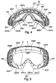
figure 5 est une vue arrière du masque sans sangle et sans élément de confort ; - la
figure 6 est une vue de dessus du masque sans sangle et sans élément de confort ; - la
figure 7 est une vue de dessous du masque sans sangle et sans élément de confort.
- the
figure 1 is a front perspective view of the mask according to a first embodiment of the invention; - the
figure 2 is a rear perspective view of the mask without strap provided with several comfort elements; - the
figure 3 is a rear perspective view of the mask without strap provided with a single comfort element; - the
figure 4 is a rear perspective view of the mask without strap and without comfort element; - the
figure 5 is a back view of the mask without strap and without comfort element; - the
figure 6 is a top view of the mask without strap and without comfort element; - the
figure 7 is a bottom view of the mask without strap and without comfort element.
Le masque 1 comprend un châssis 2 supportant un écran de protection oculaire 3. Une sangle 4 est fixée aux extrémités latérales du châssis 2. La sangle 4 et le châssis 2 forment une boucle destinée à entourer le crâne de l'utilisateur pour assurer le maintien en place du masque.The mask 1 comprises a
Dans la suite de la description, il sera fait usage de termes tels que « horizontal », « vertical », « supérieur », « inférieur », « haut », « bas », « avant », « arrière », « devant », « derrière », « antérieur », « postérieur ». Ces termes doivent être interprétés, de façon relative, en relation avec la position normale que le masque occupe sur le visage de l'utilisateur quand il se tient debout, tête droite. Par « arrière » ou « postérieure », on désigne les parties orientées côté tête / yeux de l'utilisateur.In the remainder of the description, terms such as "horizontal", "vertical", "upper", "lower", "up", "down", "front", "back", "front" will be used. , "Behind", "anterior", "posterior". These terms should be interpreted, relatively, in relation to the normal position that the mask occupies on the face of the user when he is standing, head straight. By "back" or "posterior" is meant the parts oriented head / eyes side of the user.
Dans cet exemple, le châssis 2 comprend un corps 22 et deux attaches latérales 21A, 21B. Chaque attache latérale est fixée sur un bord latéral du corps, de part et d'autre de l'écran 3. Chaque extrémité de la sangle 4 est solidaire d'une attache latérale.In this example, the
Le corps 22 comprend une partie antérieure 221 et une partie postérieure 222. Ces deux parties sont reliées entre elles par des éléments de liaison 223.The
La partie antérieure 221 supporte l'écran 3 et les deux attaches latérales 21A, 21 B. L'écran peut être assemblé de manière amovible ou non à la partie antérieure. Dans une variante, le châssis 2 comprend un cadre rigide supportant l'écran. Dans ce cas, la partie antérieure du châssis est alors fixée sur ce cadre rigide. Les attaches latérales peuvent être une partie du cadre rigide ou, alternativement, une pièce rapportée au cadre rigide ou au châssis.The
La partie postérieure 222 est agencée à l'arrière du châssis. Elle constitue la partie du châssis la plus proche du visage de l'utilisateur lorsque le masque est porté. Selon l'invention, la partie postérieure comprend au moins deux parois postérieures 2221a, 2221b, 2221c distinctes. Dans cet exemple, la partie postérieure est composée de quatre parois postérieures distinctes. Une première paroi postérieure supérieure 2221a recouvre une partie du front. Une deuxième paroi postérieure latérale gauche 2221b et une troisième paroi postérieure latérale droite 2221c recouvrent respectivement une partie des pommettes gauche et droite de l'utilisateur. Une quatrième paroi postérieure inférieure 2221 d recouvre le dessus du nez. Chaque paroi postérieure comprend une surface postérieure 2222a, 2222b, 2222c, 2222d formant la face arrière de la paroi postérieure associée.The
Chaque paroi postérieure ou la plupart des parois postérieures est sensiblement verticale lorsque le masque est porté, tête droite. Une paroi postérieure est « sensiblement verticale » lorsque sa surface postérieure, non sollicitée, est agencée de sorte que la direction normale à chaque point de la surface postérieure est orientée par rapport à un plan horizontal d'un angle compris entre 0° et 30°.Each posterior wall or most of the posterior walls is substantially vertical when the mask is worn, head straight. A posterior wall is "substantially vertical" when its unsolicited posterior surface is arranged so that the normal direction at each point of the posterior surface is oriented with respect to a horizontal plane of an angle between 0 ° and 30 °. .
Localement, une paroi postérieure peut ne pas être « verticale » pour mieux s'adapter à la morphologie de l'utilisateur. Par exemple, ce peut être le cas pour épouser la forme du nez. Dans notre mode de réalisation, la quatrième paroi postérieure inférieure 2221d, couvrant le dessus du nez, peut comprendre des zones de la paroi postérieure plus inclinées.Locally, a posterior wall may not be "vertical" to better adapt to the morphology of the user. For example, this may be the case for marrying the shape of the nose. In our embodiment, the fourth
Avantageusement, chaque surface postérieure n'est pas plane mais courbe gauche afin de mieux se conformer à la morphologie du visage. Par exemple, la surface postérieure supérieure 2221a forme un cylindre autour d'un axe sensiblement vertical pour suivre la courbure du front, dans un plan horizontal. En variante, elle peut être légèrement bombée.Advantageously, each posterior surface is not flat but curved left to better conform to the morphology of the face. For example, the
Chaque surface postérieure forme une surface d'appui du châssis en direction du visage. Dans cet exemple, chaque surface postérieure est allongée et sa longueur L2221 est au moins quatre fois supérieure à sa hauteur h2221. Cela permet un appui stable et une bonne répartition de la pression sur une zone délimitée. La surface postérieure peut être rectangulaire, comme l'est la surface postérieure de la première paroi postérieure supérieure 2221a. La surface postérieure peut aussi ne pas être rectiligne et suivre une courbe, formant une parenthèse, comme le sont les surfaces postérieures des deuxième paroi postérieure latérale gauche 2221b et troisième paroi postérieure latérale droite 2221c, ou formant un « V » pour la quatrième paroi postérieure inférieure 2221 d.Each posterior surface forms a bearing surface of the frame towards the face. In this example, each posterior surface is elongated and its length L2221 is at least four times greater than its height h2221. This allows a stable support and a good distribution of pressure on a defined area. The posterior surface may be rectangular, as is the posterior surface of the first
Chaque paroi postérieure 2221a, 2221b, 2221c forme une bande allongée de faible épaisseur e2221. Dans cet exemple, l'épaisseur de chaque paroi postérieure est au moins quatre fois inférieure à la hauteur de cette paroi postérieure. Selon un mode de réalisation, l'épaisseur e2221 est sensiblement constante. Alternativement, l'épaisseur est variable.Each
Les parois postérieures 2221a, 2221b, 2221c, 2221d sont agencées de sorte que les surfaces postérieures associées 2222a, 2222b, 2222c, 2222d forment une boucle discontinue entourant les deux yeux en recouvrant une partie du front, une partie des tempes et des pommettes et le dessus du nez. L'ouverture délimitée par cette boucle discontinue est suffisamment grande pour ne pas pénaliser le champ de vision.The
Chaque surface postérieure est destinée à venir en appui sur le visage, soit directement, soit par l'intermédiaire d'un élément de confort 5. Pour améliorer le confort de portage, il est préférable d'ajouter un élément de confort. Dans ce cas, l'élément de confort est supporté par les surfaces postérieures. Il s'agit généralement d'une mousse collée sur les surfaces postérieures. La mousse peut être en PolyUréthane (PU), en PolyEthylène (PE), en Ethylène-Acétate de Vinyle (EVA). Alternativement, l'élément de confort peut être un tissu, une poche d'air ou un autre élément adapté. L'accroche de l'élément de confort peut être réalisé autrement que par de la colle, par exemple par soudure ou bi-injection. L'élément de confort peut être aussi amovible. Dans ce cas, l'accroche de l'élément de confort peut être réalisée par des crochets, des clips ou un autre moyen.Each posterior surface is intended to bear on the face, either directly or via a
L'élément de confort peut comprendre plusieurs pièces distinctes, chaque pièce distincte étant associée à une seule surface postérieure, comme représenté aux
Alternativement, comme représenté à la
L'invention porte sur le fait que les surfaces postérieures, en interface avec le visage ou un élément de confort, forment un pourtour discontinue. Pour cela, les parois postérieures 2221a, 2221 b, 2221c supportant les surfaces postérieures 2222a, 2222b, 2222c sont espacées entre elles par un intervalle 2223 s'étendant, en direction de la partie antérieure 221 du châssis, d'une profondeur e2223 au moins égale, et avantageusement supérieure, à l'épaisseur e2221 de la paroi postérieure 2221 a, 2221b, 2221c. Autrement dit, deux parois postérieures voisines sont séparées, l'une de l'autre, par un évidement dont la profondeur e2223 est au moins égale à l'épaisseur maximale e2221 des parois postérieures. L'intervalle 2223 entre deux parois postérieures s'étend sur toute la hauteur h2221 des parois postérieures. Cette séparation entre les deux parois postérieures voisines permet un débattement différent d'une paroi postérieure par rapport à l'autre ce qui améliore l'adaptation morphologique.The invention relates to the fact that the posterior surfaces, interfacing with the face or a comfort element, form a discontinuous periphery. For this, the
Pour améliorer le degré de liberté de mouvement d'une paroi postérieure par rapport à une paroi postérieure voisine, il suffit d'augmenter la profondeur e2223 de l'intervalle 2223. En conséquence, avec une profondeur e2223 de l'intervalle 2223 au moins supérieure au quart de l'épaisseur e2 du châssis, au niveau de cet intervalle, les surfaces postérieures ont davantage de mobilité entre elles, ce qui améliore le confort de portage, quelle que soit la forme du visage de l'utilisateur. L'intervalle ne s'étend pas nécessairement de manière rectiligne.To improve the degree of freedom of movement of a posterior wall relative to a neighboring posterior wall, it suffices to increase the depth e2223 of the
La mobilité des parois postérieures 2221 a, 2221 b, 2221 c, 2221 d dépend également de leur liaison avec la partie antérieure 221 du châssis 2. En conséquence, les éléments de liaison 223 contribuent fortement au degré de liberté des parois postérieures 2221 a, 2221b, 2221c, 2221d formant la partie postérieure 222 du châssis. Ainsi, le dimensionnement de ces éléments de liaison permet d'avoir des parois postérieures mobiles ou, à l'inverse, un peu plus rigides, en fonction des zones d'appuis visage concernées.The mobility of the
Dans notre exemple, les éléments de liaison 223 se présentent sous la forme d'un ensemble de poutres reliant la partie antérieure à la partie postérieure. Les poutres sont orientées de sorte à faciliter le déplacement des parois postérieures en direction de la partie antérieure. Pour cela, les poutres ne relient pas directement la partie antérieure à la partie postérieure selon une direction linéaire normale aux surfaces postérieures correspondantes mais les poutres sont inclinées par rapport à ces directions normales. Ainsi, lorsqu'une pression est exercée sur une paroi postérieure, du fait de cet agencement des poutres, cette pression génère un effort latéral sur les poutres qui peuvent alors facilement fléchir. Les poutres sont suffisamment espacées pour créer des ouvertures. Celles-ci facilitent la déformation des poutres. Une poutre déformée ne vient pas en contact avec une autre poutre. De plus, ces ouvertures permettent d'aérer le volume intérieur du masque, entre l'écran et le visage.In our example, the connecting
Selon un mode de réalisation, les poutres forment une courbe ou un arc de cercle, comme c'est le cas pour les parois postérieures latérales 2221b, 2221c. Cette orientation facilite également la déformation des poutres permettant le déplacement des parois postérieures latérales en direction de l'écran.According to one embodiment, the beams form a curve or an arc of a circle, as is the case for the lateral
Le dimensionnement, l'orientation, l'agencement et le nombre de poutres formant les éléments de liaison caractérisent ainsi la mobilité de la paroi postérieure associée. En conséquence, chaque paroi postérieure peut avoir une mobilité différente d'une paroi postérieure voisine. Cette variation de mobilité est également due à l'intervalle séparant deux parois postérieures voisines. Les éléments de liaison peuvent être dimensionnés de sorte à permettre le déplacement ou la déformation d'au moins une surface postérieure indépendamment des autres surfaces postérieures. De plus, les moyens de liaison peuvent être dimensionnés de sorte que l'amplitude du déplacement ou de la déformation d'au moins une surface postérieure est différente de celle d'une autre surface postérieure. Cela permet d'avoir des pressions de contact différentes dans les différentes zones d'appui visage. La variation d'amplitude améliore également l'adaptation morphologique du châssis.The dimensioning, orientation, arrangement and number of beams forming the connecting elements thus characterize the mobility of the associated posterior wall. Consequently, each posterior wall may have a mobility different from a neighboring posterior wall. This mobility variation is also due to the interval separating two adjacent posterior walls. The connecting members may be dimensioned to permit movement or deformation of at least one posterior surface independently of other posterior surfaces. In addition, the connecting means may be dimensioned so that the amplitude of displacement or deformation of at least one posterior surface is different from that of another posterior surface. This makes it possible to have different contact pressures in the different areas of face support. The variation of amplitude also improves the morphological adaptation of the frame.
Les éléments de liaisons peuvent également être agencés de sorte à permettre un pivotement de la paroi postérieure sensiblement autour de son axe longitudinal. Par exemple, pour la première paroi postérieure supérieure 2221a, l'ensemble des poutres formant les éléments de liaison sont sensiblement alignés dans un même plan horizontal. Les poutres étant nettement moins hautes que la paroi postérieure supérieure, la paroi postérieure peut pivoter autour d'un axe horizontal. La paroi postérieure supérieure peut s'incliner vers l'avant ou vers l'arrière grâce à cette construction. Cela améliore davantage l'adaptation morphologique au niveau du front. Ainsi, les froncements du front n'ont pas de répercussions sur les autres appuis du masque sur le visage.The link members may also be arranged to allow pivoting of the posterior wall substantially about its longitudinal axis. For example, for the first upper
Dans notre exemple, la quatrième paroi postérieure inférieure 2221 d recouvrant le dessus du nez est reliée de manière relativement rigide à la partie antérieure. Cette quatrième paroi postérieure est donc peu mobile.In our example, the fourth lower
Selon un mode de réalisation, une des surfaces postérieures distinctes recouvre, ou est en appui sur, uniquement une partie du front, légèrement au-dessus des sourcils. La longueur L2221 de cette surface postérieure est au moins égale à la moitié de la distance entre les bords latéraux du châssis. Alternativement, outre une partie du front, cette surface recouvre, ou est en appui sur, une partie des pommettes. Cependant, cette surface postérieure distincte ne recouvre pas une partie du nez.According to one embodiment, one of the distinct posterior surfaces covers, or bears on, only a portion of the forehead, slightly above the eyebrows. The length L2221 of this posterior surface is at least equal to half the distance between the lateral edges of the frame. Alternatively, in addition to a portion of the forehead, this surface covers, or bears on, a portion of the cheekbones. However, this distinct posterior surface does not cover part of the nose.
Dans cet exemple, le châssis n'est pas un élément de confort, il assure alors un maintien des éléments du masque. A ce titre, le châssis présente des propriétés mécaniques permettant d'assurer cette tenue. Le châssis est unitaire et composé d'un matériau dont la dureté est supérieure à 70 Shore A (mesurée selon ISO 868 et 7619, ASTM D 2240 et DIN 53505). Selon un mode de réalisation, le châssis est en PolyUréthane (PU) ce qui permet d'obtenir les caractéristiques précédentes recherchées. Dans ce cas, le châssis n'est pas constitué d'une mousse.In this example, the frame is not an element of comfort, it then ensures a maintenance of the elements of the mask. As such, the chassis has mechanical properties to ensure this holding. The frame is unitary and composed of a material with a hardness greater than 70 Shore A (measured according to ISO 868 and 7619, ASTM D 2240 and DIN 53505). According to one embodiment, the frame is made of Polyurethane (PU), which makes it possible to obtain the preceding characteristics desired. In this case, the frame is not made of a foam.
L'invention n'est pas limitée à ces modes de réalisation. Il est possible de combiner ces modes de réalisationThe invention is not limited to these embodiments. It is possible to combine these embodiments
L'invention n'est pas limitée aux modes de réalisation précédemment décrits mais s'étend à tous les modes de réalisation couverts par les revendications annexées.The invention is not limited to the previously described embodiments but extends to all the embodiments covered by the appended claims.
- 1-1-
- MasqueMask
- 2-2-
-
Châssis
e2 Epaisseur châssis
21- Attache latérale
22- Corps
221- Partie antérieure
222- Partie postérieure
2221 a, b, c, d- Paroi postérieure
e2221 Epaisseur paroi postérieure
h2221 Hauteur paroi postérieure
L2221 Longueur paroi postérieure
2222 a, b, c, d- Surface postérieure
2223 Intervalle
e2223 Profondeur intervalleFrame
e2 Chassis thickness
21- Lateral fastener
22- Body
221- Anterior part
222- Posterior portion
2221 a, b, c, d- Posterior wall
e2221 Posterior wall thickness
h2221 Posterior wall height
L2221 Posterior wall length
2222 a, b, c, d- Posterior surface
2223 Interval
e2223 Depth interval - 223-223-
- Elément de liaisonConnecting element
- 3-3-
- EcranScreen
- 4-4-
- SangleStrap
- 5-5-
- Elément de confortComfort element
Claims (15)
caractérisé en ce que
la partie postérieure du châssis comprend au moins deux surfaces postérieures (2222a, 2222b, 2222c) distinctes, chaque surface postérieure formant la face arrière d'une paroi postérieure (2221a, 2221b, 2222c) sensiblement verticale, les parois postérieures étant agencées de sorte que les surfaces postérieures associées forment une boucle discontinue entourant les deux yeux en recouvrant une partie du front, une partie des tempes et des pommettes et le dessus du nez, les parois postérieures étant espacées entre elles par un intervalle (2223) s'étendant, en direction de la partie antérieure du châssis, d'une profondeur (e2223) au moins égale à l'épaisseur (e2221) des parois postérieures délimitant l'intervalle.
characterized in that
the rear part of the frame comprises at least two distinct posterior surfaces (2222a, 2222b, 2222c), each posterior surface forming the rear face of a rear wall (2221a, 2221b, 2222c) substantially vertical, the rear walls being arranged so that the associated posterior surfaces form a discontinuous loop surrounding the two eyes covering a portion of the forehead, part of the temples and cheekbones and the top of the nose, the posterior walls being spaced apart by an interval (2223) extending, direction of the front part of the frame, a depth (e2223) at least equal to the thickness (e2221) of the rear walls delimiting the interval.
Applications Claiming Priority (1)
| Application Number | Priority Date | Filing Date | Title |
|---|---|---|---|
| FR1500379A FR3033133A1 (en) | 2015-02-27 | 2015-02-27 | SPORTS MASK |
Publications (2)
| Publication Number | Publication Date |
|---|---|
| EP3061431A1 true EP3061431A1 (en) | 2016-08-31 |
| EP3061431B1 EP3061431B1 (en) | 2017-10-25 |
Family
ID=52824400
Family Applications (1)
| Application Number | Title | Priority Date | Filing Date |
|---|---|---|---|
| EP16000288.7A Active EP3061431B1 (en) | 2015-02-27 | 2016-02-05 | Sports goggles |
Country Status (2)
| Country | Link |
|---|---|
| EP (1) | EP3061431B1 (en) |
| FR (1) | FR3033133A1 (en) |
Cited By (1)
| Publication number | Priority date | Publication date | Assignee | Title |
|---|---|---|---|---|
| WO2024040311A1 (en) * | 2022-08-25 | 2024-02-29 | ResMed Pty Ltd | Interfacing structure for eyewear |
Citations (7)
| Publication number | Priority date | Publication date | Assignee | Title |
|---|---|---|---|---|
| US1677747A (en) * | 1924-11-01 | 1928-07-17 | E B Meyrowitz Inc | Goggles |
| US1942394A (en) * | 1927-06-15 | 1934-01-09 | American Optical Corp | Goggles |
| DE858289C (en) * | 1951-05-30 | 1952-12-04 | Fritz Zapletal | All-vision goggles |
| EP0167422A1 (en) * | 1984-05-21 | 1986-01-08 | ETABLISSEMENTS BOLLE Georges, Robert et Maurice | Mask having a support on the face |
| WO1999011207A1 (en) * | 1997-09-05 | 1999-03-11 | Harges Cordell Frank Jr | Firefighter goggle |
| WO2004031839A2 (en) * | 2002-10-01 | 2004-04-15 | Pan-Optx, Inc. | Eyecup for glasses |
| EP2380538A1 (en) | 2010-04-22 | 2011-10-26 | Salomon S.A.S. | Protective goggles for the practice of outdoor sports |
-
2015
- 2015-02-27 FR FR1500379A patent/FR3033133A1/en not_active Withdrawn
-
2016
- 2016-02-05 EP EP16000288.7A patent/EP3061431B1/en active Active
Patent Citations (7)
| Publication number | Priority date | Publication date | Assignee | Title |
|---|---|---|---|---|
| US1677747A (en) * | 1924-11-01 | 1928-07-17 | E B Meyrowitz Inc | Goggles |
| US1942394A (en) * | 1927-06-15 | 1934-01-09 | American Optical Corp | Goggles |
| DE858289C (en) * | 1951-05-30 | 1952-12-04 | Fritz Zapletal | All-vision goggles |
| EP0167422A1 (en) * | 1984-05-21 | 1986-01-08 | ETABLISSEMENTS BOLLE Georges, Robert et Maurice | Mask having a support on the face |
| WO1999011207A1 (en) * | 1997-09-05 | 1999-03-11 | Harges Cordell Frank Jr | Firefighter goggle |
| WO2004031839A2 (en) * | 2002-10-01 | 2004-04-15 | Pan-Optx, Inc. | Eyecup for glasses |
| EP2380538A1 (en) | 2010-04-22 | 2011-10-26 | Salomon S.A.S. | Protective goggles for the practice of outdoor sports |
Cited By (1)
| Publication number | Priority date | Publication date | Assignee | Title |
|---|---|---|---|---|
| WO2024040311A1 (en) * | 2022-08-25 | 2024-02-29 | ResMed Pty Ltd | Interfacing structure for eyewear |
Also Published As
| Publication number | Publication date |
|---|---|
| EP3061431B1 (en) | 2017-10-25 |
| FR3033133A1 (en) | 2016-09-02 |
Similar Documents
| Publication | Publication Date | Title |
|---|---|---|
| EP0682885B2 (en) | Device for retaining a helmet on the occiput | |
| FR2626683A1 (en) | Toroidal lens for sunglasses | |
| FR2978904A1 (en) | HELMET ASSEMBLY AND EYE PROTECTION MASK | |
| EP2380536A1 (en) | Protective goggles for the practice of outdoor sports | |
| EP2380538B1 (en) | Protective goggles for the practice of outdoor sports | |
| EP2380537A1 (en) | Protective goggles for the practice of outdoor sports | |
| EP3028685A1 (en) | Mask with comfort element | |
| EP3106061A1 (en) | Carrying item | |
| EP3061431B1 (en) | Sports goggles | |
| EP3195743B1 (en) | Body protection equipment with retention strap and shells | |
| EP2919727B1 (en) | Goggles with a detachable shield | |
| WO2016008902A1 (en) | Protective helmet with built-in mobile visor | |
| FR2814349A1 (en) | BACKPACK | |
| EP3743672B1 (en) | Bag carrier and apparatus comprising such a bag carrier | |
| EP3231307A1 (en) | Sports helmet | |
| WO2015193794A1 (en) | Helmet equipped with goggles, in particular for skiing or motorcycling | |
| FR3091992A1 (en) | Sports mask | |
| EP2786666B1 (en) | Protective equipment including at least one removable shoulder protection | |
| EP1496763A2 (en) | Shoe bottom | |
| EP4119104B1 (en) | Sole for flexible blade | |
| EP3883427B1 (en) | Strap for carrying comprising a conformation frame | |
| CA2518739A1 (en) | Spectacles for a helmet and helmet fitted with said spectacles | |
| WO2018060469A1 (en) | Body armour protective vest | |
| FR3031013A1 (en) | DEVICE FOR PROTECTING THE HEAD WITH AROUND THE NECK, AND ASSOCIATED ACCESSORY SUCH AS A GARMENT | |
| EP3141228A1 (en) | Sports mask |
Legal Events
| Date | Code | Title | Description |
|---|---|---|---|
| PUAI | Public reference made under article 153(3) epc to a published international application that has entered the european phase |
Free format text: ORIGINAL CODE: 0009012 |
|
| AK | Designated contracting states |
Kind code of ref document: A1 Designated state(s): AL AT BE BG CH CY CZ DE DK EE ES FI FR GB GR HR HU IE IS IT LI LT LU LV MC MK MT NL NO PL PT RO RS SE SI SK SM TR |
|
| AX | Request for extension of the european patent |
Extension state: BA ME |
|
| 17P | Request for examination filed |
Effective date: 20170210 |
|
| GRAP | Despatch of communication of intention to grant a patent |
Free format text: ORIGINAL CODE: EPIDOSNIGR1 |
|
| INTG | Intention to grant announced |
Effective date: 20170517 |
|
| GRAS | Grant fee paid |
Free format text: ORIGINAL CODE: EPIDOSNIGR3 |
|
| GRAA | (expected) grant |
Free format text: ORIGINAL CODE: 0009210 |
|
| AK | Designated contracting states |
Kind code of ref document: B1 Designated state(s): AL AT BE BG CH CY CZ DE DK EE ES FI FR GB GR HR HU IE IS IT LI LT LU LV MC MK MT NL NO PL PT RO RS SE SI SK SM TR |
|
| REG | Reference to a national code |
Ref country code: GB Ref legal event code: FG4D Free format text: NOT ENGLISH |
|
| REG | Reference to a national code |
Ref country code: CH Ref legal event code: EP |
|
| REG | Reference to a national code |
Ref country code: AT Ref legal event code: REF Ref document number: 939203 Country of ref document: AT Kind code of ref document: T Effective date: 20171115 |
|
| REG | Reference to a national code |
Ref country code: IE Ref legal event code: FG4D Free format text: LANGUAGE OF EP DOCUMENT: FRENCH |
|
| REG | Reference to a national code |
Ref country code: DE Ref legal event code: R096 Ref document number: 602016000602 Country of ref document: DE |
|
| REG | Reference to a national code |
Ref country code: FR Ref legal event code: PLFP Year of fee payment: 3 |
|
| REG | Reference to a national code |
Ref country code: NL Ref legal event code: MP Effective date: 20171025 |
|
| REG | Reference to a national code |
Ref country code: LT Ref legal event code: MG4D |
|
| REG | Reference to a national code |
Ref country code: AT Ref legal event code: MK05 Ref document number: 939203 Country of ref document: AT Kind code of ref document: T Effective date: 20171025 |
|
| PG25 | Lapsed in a contracting state [announced via postgrant information from national office to epo] |
Ref country code: NL Free format text: LAPSE BECAUSE OF FAILURE TO SUBMIT A TRANSLATION OF THE DESCRIPTION OR TO PAY THE FEE WITHIN THE PRESCRIBED TIME-LIMIT Effective date: 20171025 |
|
| PG25 | Lapsed in a contracting state [announced via postgrant information from national office to epo] |
Ref country code: LT Free format text: LAPSE BECAUSE OF FAILURE TO SUBMIT A TRANSLATION OF THE DESCRIPTION OR TO PAY THE FEE WITHIN THE PRESCRIBED TIME-LIMIT Effective date: 20171025 Ref country code: NO Free format text: LAPSE BECAUSE OF FAILURE TO SUBMIT A TRANSLATION OF THE DESCRIPTION OR TO PAY THE FEE WITHIN THE PRESCRIBED TIME-LIMIT Effective date: 20180125 Ref country code: ES Free format text: LAPSE BECAUSE OF FAILURE TO SUBMIT A TRANSLATION OF THE DESCRIPTION OR TO PAY THE FEE WITHIN THE PRESCRIBED TIME-LIMIT Effective date: 20171025 Ref country code: SE Free format text: LAPSE BECAUSE OF FAILURE TO SUBMIT A TRANSLATION OF THE DESCRIPTION OR TO PAY THE FEE WITHIN THE PRESCRIBED TIME-LIMIT Effective date: 20171025 Ref country code: FI Free format text: LAPSE BECAUSE OF FAILURE TO SUBMIT A TRANSLATION OF THE DESCRIPTION OR TO PAY THE FEE WITHIN THE PRESCRIBED TIME-LIMIT Effective date: 20171025 |
|
| PG25 | Lapsed in a contracting state [announced via postgrant information from national office to epo] |
Ref country code: LV Free format text: LAPSE BECAUSE OF FAILURE TO SUBMIT A TRANSLATION OF THE DESCRIPTION OR TO PAY THE FEE WITHIN THE PRESCRIBED TIME-LIMIT Effective date: 20171025 Ref country code: AT Free format text: LAPSE BECAUSE OF FAILURE TO SUBMIT A TRANSLATION OF THE DESCRIPTION OR TO PAY THE FEE WITHIN THE PRESCRIBED TIME-LIMIT Effective date: 20171025 Ref country code: HR Free format text: LAPSE BECAUSE OF FAILURE TO SUBMIT A TRANSLATION OF THE DESCRIPTION OR TO PAY THE FEE WITHIN THE PRESCRIBED TIME-LIMIT Effective date: 20171025 Ref country code: GR Free format text: LAPSE BECAUSE OF FAILURE TO SUBMIT A TRANSLATION OF THE DESCRIPTION OR TO PAY THE FEE WITHIN THE PRESCRIBED TIME-LIMIT Effective date: 20180126 Ref country code: IS Free format text: LAPSE BECAUSE OF FAILURE TO SUBMIT A TRANSLATION OF THE DESCRIPTION OR TO PAY THE FEE WITHIN THE PRESCRIBED TIME-LIMIT Effective date: 20180225 Ref country code: RS Free format text: LAPSE BECAUSE OF FAILURE TO SUBMIT A TRANSLATION OF THE DESCRIPTION OR TO PAY THE FEE WITHIN THE PRESCRIBED TIME-LIMIT Effective date: 20171025 Ref country code: BG Free format text: LAPSE BECAUSE OF FAILURE TO SUBMIT A TRANSLATION OF THE DESCRIPTION OR TO PAY THE FEE WITHIN THE PRESCRIBED TIME-LIMIT Effective date: 20180125 |
|
| REG | Reference to a national code |
Ref country code: DE Ref legal event code: R097 Ref document number: 602016000602 Country of ref document: DE |
|
| PG25 | Lapsed in a contracting state [announced via postgrant information from national office to epo] |
Ref country code: SK Free format text: LAPSE BECAUSE OF FAILURE TO SUBMIT A TRANSLATION OF THE DESCRIPTION OR TO PAY THE FEE WITHIN THE PRESCRIBED TIME-LIMIT Effective date: 20171025 Ref country code: CZ Free format text: LAPSE BECAUSE OF FAILURE TO SUBMIT A TRANSLATION OF THE DESCRIPTION OR TO PAY THE FEE WITHIN THE PRESCRIBED TIME-LIMIT Effective date: 20171025 Ref country code: EE Free format text: LAPSE BECAUSE OF FAILURE TO SUBMIT A TRANSLATION OF THE DESCRIPTION OR TO PAY THE FEE WITHIN THE PRESCRIBED TIME-LIMIT Effective date: 20171025 Ref country code: DK Free format text: LAPSE BECAUSE OF FAILURE TO SUBMIT A TRANSLATION OF THE DESCRIPTION OR TO PAY THE FEE WITHIN THE PRESCRIBED TIME-LIMIT Effective date: 20171025 Ref country code: CY Free format text: LAPSE BECAUSE OF FAILURE TO SUBMIT A TRANSLATION OF THE DESCRIPTION OR TO PAY THE FEE WITHIN THE PRESCRIBED TIME-LIMIT Effective date: 20171025 |
|
| PG25 | Lapsed in a contracting state [announced via postgrant information from national office to epo] |
Ref country code: RO Free format text: LAPSE BECAUSE OF FAILURE TO SUBMIT A TRANSLATION OF THE DESCRIPTION OR TO PAY THE FEE WITHIN THE PRESCRIBED TIME-LIMIT Effective date: 20171025 Ref country code: IT Free format text: LAPSE BECAUSE OF FAILURE TO SUBMIT A TRANSLATION OF THE DESCRIPTION OR TO PAY THE FEE WITHIN THE PRESCRIBED TIME-LIMIT Effective date: 20171025 Ref country code: SM Free format text: LAPSE BECAUSE OF FAILURE TO SUBMIT A TRANSLATION OF THE DESCRIPTION OR TO PAY THE FEE WITHIN THE PRESCRIBED TIME-LIMIT Effective date: 20171025 Ref country code: PL Free format text: LAPSE BECAUSE OF FAILURE TO SUBMIT A TRANSLATION OF THE DESCRIPTION OR TO PAY THE FEE WITHIN THE PRESCRIBED TIME-LIMIT Effective date: 20171025 |
|
| PLBE | No opposition filed within time limit |
Free format text: ORIGINAL CODE: 0009261 |
|
| STAA | Information on the status of an ep patent application or granted ep patent |
Free format text: STATUS: NO OPPOSITION FILED WITHIN TIME LIMIT |
|
| PG25 | Lapsed in a contracting state [announced via postgrant information from national office to epo] |
Ref country code: MC Free format text: LAPSE BECAUSE OF FAILURE TO SUBMIT A TRANSLATION OF THE DESCRIPTION OR TO PAY THE FEE WITHIN THE PRESCRIBED TIME-LIMIT Effective date: 20171025 Ref country code: MT Free format text: LAPSE BECAUSE OF FAILURE TO SUBMIT A TRANSLATION OF THE DESCRIPTION OR TO PAY THE FEE WITHIN THE PRESCRIBED TIME-LIMIT Effective date: 20171025 |
|
| 26N | No opposition filed |
Effective date: 20180726 |
|
| REG | Reference to a national code |
Ref country code: IE Ref legal event code: MM4A |
|
| REG | Reference to a national code |
Ref country code: BE Ref legal event code: MM Effective date: 20180228 |
|
| PG25 | Lapsed in a contracting state [announced via postgrant information from national office to epo] |
Ref country code: SI Free format text: LAPSE BECAUSE OF FAILURE TO SUBMIT A TRANSLATION OF THE DESCRIPTION OR TO PAY THE FEE WITHIN THE PRESCRIBED TIME-LIMIT Effective date: 20171025 Ref country code: LU Free format text: LAPSE BECAUSE OF NON-PAYMENT OF DUE FEES Effective date: 20180205 |
|
| PG25 | Lapsed in a contracting state [announced via postgrant information from national office to epo] |
Ref country code: IE Free format text: LAPSE BECAUSE OF NON-PAYMENT OF DUE FEES Effective date: 20180205 |
|
| PG25 | Lapsed in a contracting state [announced via postgrant information from national office to epo] |
Ref country code: BE Free format text: LAPSE BECAUSE OF NON-PAYMENT OF DUE FEES Effective date: 20180228 |
|
| REG | Reference to a national code |
Ref country code: CH Ref legal event code: PL |
|
| PG25 | Lapsed in a contracting state [announced via postgrant information from national office to epo] |
Ref country code: LI Free format text: LAPSE BECAUSE OF NON-PAYMENT OF DUE FEES Effective date: 20190228 Ref country code: CH Free format text: LAPSE BECAUSE OF NON-PAYMENT OF DUE FEES Effective date: 20190228 |
|
| PG25 | Lapsed in a contracting state [announced via postgrant information from national office to epo] |
Ref country code: TR Free format text: LAPSE BECAUSE OF FAILURE TO SUBMIT A TRANSLATION OF THE DESCRIPTION OR TO PAY THE FEE WITHIN THE PRESCRIBED TIME-LIMIT Effective date: 20171025 |
|
| PG25 | Lapsed in a contracting state [announced via postgrant information from national office to epo] |
Ref country code: PT Free format text: LAPSE BECAUSE OF FAILURE TO SUBMIT A TRANSLATION OF THE DESCRIPTION OR TO PAY THE FEE WITHIN THE PRESCRIBED TIME-LIMIT Effective date: 20171025 |
|
| PG25 | Lapsed in a contracting state [announced via postgrant information from national office to epo] |
Ref country code: MK Free format text: LAPSE BECAUSE OF NON-PAYMENT OF DUE FEES Effective date: 20171025 Ref country code: HU Free format text: LAPSE BECAUSE OF FAILURE TO SUBMIT A TRANSLATION OF THE DESCRIPTION OR TO PAY THE FEE WITHIN THE PRESCRIBED TIME-LIMIT; INVALID AB INITIO Effective date: 20160205 |
|
| PG25 | Lapsed in a contracting state [announced via postgrant information from national office to epo] |
Ref country code: AL Free format text: LAPSE BECAUSE OF FAILURE TO SUBMIT A TRANSLATION OF THE DESCRIPTION OR TO PAY THE FEE WITHIN THE PRESCRIBED TIME-LIMIT Effective date: 20171025 |
|
| GBPC | Gb: european patent ceased through non-payment of renewal fee |
Effective date: 20200205 |
|
| PG25 | Lapsed in a contracting state [announced via postgrant information from national office to epo] |
Ref country code: GB Free format text: LAPSE BECAUSE OF NON-PAYMENT OF DUE FEES Effective date: 20200205 |
|
| PGFP | Annual fee paid to national office [announced via postgrant information from national office to epo] |
Ref country code: FR Payment date: 20231229 Year of fee payment: 9 |
|
| P01 | Opt-out of the competence of the unified patent court (upc) registered |
Effective date: 20240315 |
|
| PGFP | Annual fee paid to national office [announced via postgrant information from national office to epo] |
Ref country code: DE Payment date: 20231229 Year of fee payment: 9 |