EP3060721B1 - Grinding motor and method of operating the same for rail applications - Google Patents
Grinding motor and method of operating the same for rail applications Download PDFInfo
- Publication number
- EP3060721B1 EP3060721B1 EP14855115.3A EP14855115A EP3060721B1 EP 3060721 B1 EP3060721 B1 EP 3060721B1 EP 14855115 A EP14855115 A EP 14855115A EP 3060721 B1 EP3060721 B1 EP 3060721B1
- Authority
- EP
- European Patent Office
- Prior art keywords
- grinding
- rail
- profile
- corrugation
- vehicle
- Prior art date
- Legal status (The legal status is an assumption and is not a legal conclusion. Google has not performed a legal analysis and makes no representation as to the accuracy of the status listed.)
- Active
Links
- 238000000034 method Methods 0.000 title description 38
- 239000002184 metal Substances 0.000 claims description 30
- 238000005259 measurement Methods 0.000 claims description 27
- 239000004575 stone Substances 0.000 claims description 10
- 230000000694 effects Effects 0.000 claims description 5
- 230000000994 depressogenic effect Effects 0.000 claims description 2
- 238000012545 processing Methods 0.000 description 8
- 238000013459 approach Methods 0.000 description 7
- 230000006870 function Effects 0.000 description 7
- 239000000463 material Substances 0.000 description 3
- 238000004364 calculation method Methods 0.000 description 2
- 238000004891 communication Methods 0.000 description 2
- 230000007547 defect Effects 0.000 description 2
- 230000001419 dependent effect Effects 0.000 description 2
- 238000012804 iterative process Methods 0.000 description 2
- 238000012800 visualization Methods 0.000 description 2
- 230000001133 acceleration Effects 0.000 description 1
- 238000006073 displacement reaction Methods 0.000 description 1
- 238000013213 extrapolation Methods 0.000 description 1
- 239000000446 fuel Substances 0.000 description 1
- 239000010438 granite Substances 0.000 description 1
- 238000007689 inspection Methods 0.000 description 1
- 238000012423 maintenance Methods 0.000 description 1
- 230000003278 mimic effect Effects 0.000 description 1
- 238000012986 modification Methods 0.000 description 1
- 230000004048 modification Effects 0.000 description 1
- 238000005457 optimization Methods 0.000 description 1
- 239000011236 particulate material Substances 0.000 description 1
- 238000005096 rolling process Methods 0.000 description 1
- 238000007493 shaping process Methods 0.000 description 1
- 238000006467 substitution reaction Methods 0.000 description 1
Images


Classifications
-
- B—PERFORMING OPERATIONS; TRANSPORTING
- B24—GRINDING; POLISHING
- B24B—MACHINES, DEVICES, OR PROCESSES FOR GRINDING OR POLISHING; DRESSING OR CONDITIONING OF ABRADING SURFACES; FEEDING OF GRINDING, POLISHING, OR LAPPING AGENTS
- B24B49/00—Measuring or gauging equipment for controlling the feed movement of the grinding tool or work; Arrangements of indicating or measuring equipment, e.g. for indicating the start of the grinding operation
- B24B49/12—Measuring or gauging equipment for controlling the feed movement of the grinding tool or work; Arrangements of indicating or measuring equipment, e.g. for indicating the start of the grinding operation involving optical means
-
- B—PERFORMING OPERATIONS; TRANSPORTING
- B24—GRINDING; POLISHING
- B24B—MACHINES, DEVICES, OR PROCESSES FOR GRINDING OR POLISHING; DRESSING OR CONDITIONING OF ABRADING SURFACES; FEEDING OF GRINDING, POLISHING, OR LAPPING AGENTS
- B24B19/00—Single-purpose machines or devices for particular grinding operations not covered by any other main group
- B24B19/004—Single-purpose machines or devices for particular grinding operations not covered by any other main group for grinding rails, T, I, H or other similar profiles
-
- E—FIXED CONSTRUCTIONS
- E01—CONSTRUCTION OF ROADS, RAILWAYS, OR BRIDGES
- E01B—PERMANENT WAY; PERMANENT-WAY TOOLS; MACHINES FOR MAKING RAILWAYS OF ALL KINDS
- E01B31/00—Working rails, sleepers, baseplates, or the like, in or on the line; Machines, tools, or auxiliary devices specially designed therefor
- E01B31/02—Working rail or other metal track components on the spot
- E01B31/12—Removing metal from rails, rail joints, or baseplates, e.g. for deburring welds, reconditioning worn rails
- E01B31/17—Removing metal from rails, rail joints, or baseplates, e.g. for deburring welds, reconditioning worn rails by grinding
-
- G—PHYSICS
- G01—MEASURING; TESTING
- G01B—MEASURING LENGTH, THICKNESS OR SIMILAR LINEAR DIMENSIONS; MEASURING ANGLES; MEASURING AREAS; MEASURING IRREGULARITIES OF SURFACES OR CONTOURS
- G01B11/00—Measuring arrangements characterised by the use of optical techniques
- G01B11/24—Measuring arrangements characterised by the use of optical techniques for measuring contours or curvatures
Definitions
- Railroads are typically constructed to include a pair of elongated, substantially parallel rails, which are coupled to a plurality of laterally extending ties.
- the ties are disposed on a ballast bed of hard particulate material such as sharp edged granite. Over time, normal wear and tear on the railroad may cause the rails to develop surface defects and deform in shape.
- Rail grinders are track vehicles typically used to shape the transverse section of the rail to control the wheel/rail interface and to remove longitudinal surface defects. Grinding motors may be handheld, cart mounted, or part of rail-bound machines. Rail-bound grinders have motor configurations that typically range from 10 to 96 grinding motors. These motors can be oriented at predefined angles to the cross sectional profile of the rail and have varying horsepower.
- US 5140776 discloses a strobe light, oriented directly over a railroad track rail and at a 45 DEG angle to the horizontal which projects a light line across the rail.
- a pair of cameras oriented directly over the rail view the light image on the rail.
- the light lines reflected from the foot of the rail provide a reference for numerically describing the profile of the railhead.
- the measured rail profile is compared to an ideal rail profile. The results of the comparison are used to position grinding modules for grinding the rail to a preferred profile.
- US 5134808 discloses a programming method for the re-profiling of rails according to which the track is divided in successive sections as from a starting point and for each of these sections one proceeds for each line of rails to the measuring of the wavelength and/or of the amplitudes of the longitudinal undulations of the rolling table of the rail and to the measure of the transverse profile of the head of the rail.
- a reference profile is compared to the measured transverse profile and determines the transverse metal section to be removed to correct the transverse profile of the rail, then one determines as a function of the amplitudes of the longitudinal undulations of the rail the longitudinal metal section to be removed to correct the longitudinal profile of the rail.
- the total section of metal to be removed is determined, as is the necessary number of minimal tool-passes, as a function of the speed of working, the characteristic of metal removal of each tool, and the total metal section to be removed.
- the present disclosure is directed to improved systems and methods for use in rail track maintenance such as grinding. Such an objective is achieved by a rail grinding vehicle as defined in the appended claims.
- the present invention is directed to a rail grinding vehicle adapted to perform a process for automating grinding motor orientation.
- the process utilizes rail profile inspection systems, transverse (cross-section) and longitudinal (corrugation, surface waves), and predictive metal removal equations, to provide a desired orientation and horsepower of the motors, as well as the appropriate grinding train speed.
- the process described herein may be implemented on a rail-bound machine dedicated to rail grinding processes.
- the grinding motors may be associated with other types of rail machines.
- the rail machine with grinding motors may be used with an operator, or in other embodiments, the rail machine with grinding motors may be operated as a drone vehicle (i.e., without a human operator).
- Figure 1 is a side view of a rail grinding motor 10.
- Rail grinding motor 10 is shown in partial view and a rail grinding apparatus may include many grinding motors coupled to a rail vehicle operable to travel, for example self-propelled, down the rail.
- a rail 12 is shown in cross-section.
- An orientation of a grinding head 14 may be controlled relative to the rail 12.
- the rail grinding motor 10 may be coupled to a rail vehicle by the mounts 16a and 16b.
- Actuators 18a and 18b coupled between the grinding head 14 and the rail vehicle may control the vertical and lateral orientation of the grinding head 14 relative to the rail 12.
- An actuator 20 may control an angle 22 of the grinding head 14 relative to the rail 12.
- FIG. 2 is a perspective view of an exemplary rail measurement system.
- the rail vehicle may include a measurement system 100.
- the measurement system 100 may obtain a profile measurement of the rail 12. It may be, for example, a camera system, a laser measurement system, or any other system that can obtain a dataset representative of a transverse profile of the rail. The dataset may be recorded with reference to a particular position of the rail by reference to an encoder wheel that is coupled to the rail.
- the measurement system 100 may operate continuously or may measure the rail profile periodically, for example every 3 m.
- the process according to the present disclosure may utilize real-time transverse profile measurements (e.g., returned in Cartesian coordinates via laser based rail profile measurement systems, or by other systems) as well as rail corrugation measurements (rail surface anomalies via acceleration or displacement data), to determine a manner of grinding for profile and/or corrugation.
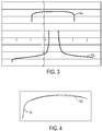
- Figure 3 depicts an exemplary transverse profile measurement of a given rail on a coordinate grid.
- the profile measurement may be continuous or may be provided in a plurality of sections 110a, 110b, etc. The number of sections (from one to many) may depend on the field of view and number of measurement sensors.
- Figure 4 depicts a selected target rail template 122 aligned against a measured rail profile 120, for example on a left side region of the top of the rail such as section 110a.
- the rail template may be a transverse shape of the rail.
- FIG. 5 is a perspective view of an exemplary rail 500 with corrugation (e.g., raised areas 502a, 502b and depressed areas 504a, 504b, and Figure 6 illustrates rail corrugation of a rail 600 as a function of depth in a generalized heat map visualization.
- Rail corrugation may be removed or reduced by rail grinding to flatten the corrugation.
- the rail may be ground by positioning one of more rail grinding motors on the rail to reshape the rail.
- the amount of metal removed from the rail by each individual motor is dependent upon a number of factors, such as the horsepower of the motor that, influence the amount of metal removed during grinding, including the speed of the vehicle, the makeup of the grinding stone, the hardness of the rail, initial shape of the rail as well as others.
- the speed of the rail-bound vehicle significantly affects the amount of metal removed during grinding, and is, in practice, one of the easier parameters to adjust to control the amount of metal removed.
- FIG. 7 An exemplary process for determining grinding mode selection is depicted in Figure 7 .
- One possible grinding mode is to grind for profile. Grinding for profile includes shaping multiple surfaces of the rail, for example the top and side of the rail, in the same operation to seek a desired finished profile.
- Another possible grinding mode is to grind for corrugation. Grinding for corrugation includes prioritizing flattening of the top of the rail to reduce corrugation by positioning more or all of the grinding motors (thereby increasing total metal removal) on the top of the rail.
- a grinding for corrugation operation may be followed by a grinding for profile operation, or vice versa.
- only a grind for profile mode may be used, or only a grind for corrugation mode may be used. If corrugation amplitude and wavelength measurements indicate that sufficient corrugation is present that can be removed via grinding, the grinding motors may be oriented to remove corrugation before adjusting profile.
- step S106 it is determined whether the wavelength may be removed by grinding through a comparison of the corrugation wavelength to the size of the grinding stone. If the wavelength may not be removed by grinding, then the grinding for profile mode is selected at step S108. If the wavelength may be removed by grinding, then the process proceeds to step S110, where it is determined whether the corrugation amplitude may be removed by grinding while preserving the work hardened layer of the rail. If the amplitude may not be removed by grinding, then the grinding for profile mode is selected at step S112.
- the grinding mode logic may assess whether the amplitude (A) of the corrugation is above a certain defined value (e.g., 0.3175 mm) at step S114. If the amplitude is above the defined value, then grinding for corrugation is selected at step S116. If the measured corrugation does not indicate that corrugation grinding should be applied, then a corrugation quality index (CQI) may be determined as step S118.
- CQI corrugation quality index
- An example of a CQI is a ratio of generated vs. acceptable dynamic impact based on the measured corrugation data. Individual railroads may define a CQI threshold that matches their individual standards. If the CQI is at or below the threshold, then grinding for corrugation is selected at step S120. If the CQI is above the threshold, then grinding for profile is selected at step S122.
- the number of passes (sequential travel over the same site) required to prepare the segment for profile grinding may be recommended to the operator. Note, the number of passes may be dependent on the number and power of the motors on the grinder. After corrugation grinding, if required, recommendations are made to the operator on the grinding pattern and grinder speed to reshape the transverse cross section of the rail to the desired shape (template). Depending on the number of grinding motors on the rail-bound grinder, the process may also predict the number of passes, and for each pass, define the grinding pattern (e.g., orientation of the grinding motors, grinding motor power) and grinder speed.
- the grinding pattern e.g., orientation of the grinding motors, grinding motor power
- grinding patterns may be automatically generated to bring the transverse rail profile to a target rail template, either to an exact match, or to within some tolerance.
- tolerances may include matching a selected profile template or optimizing passes based on user tolerances.
- the matching selected profile template approach may include infinite passes, for example using a chasing the peak grinding method such as that discussed in more detail with respect to Figure 8 .
- the optimizing the passes based on user tolerances may include specifying the number of passes, using a Grinding Quality Index (GQI) target, or using a target resource utilization technique.
- GQI Grinding Quality Index
- An example of a GQI is a ratio of the difference curve to an acceptability curve.
- the number of passes approach may include an optimal location grinding method, which may prioritize grinding on the most critical areas of the rail head, either the top of rail, gage face, gage corner, or field side.
- the GQI approach may include the optimal location grinding method and/or the chase the peak grinding method having a sufficient number of passes to achieve the GQI target.
- the target utilization approach may consider historical fuel, stone, and other usage figures to estimate the cost of the grinding operation. The grinding may stop when a certain cost for grind threshold is reached.
- optimization logic may favor specific areas of the rail such as the gage corner for priority grinding when limitations are applied.
- a chasing the peak targeted grinding method may include positioning and calibrating grinding motors in such a way as to grind the highest point on a difference curve (e.g., a normal difference between a measured transverse profile and a desired profile such as a template) as seen by each passing motor.
- the chase the peak logic utilizes information on the amount of metal needed to be removed from the rail to match a selected target template (a difference curve).
- the process may be an iterative process for n motors.
- step S204 rail profile data and a target rail template are provided.
- step S204 the rail profile data and the target rail template are aligned utilizing, for example, an area minimization routine (see, for example, Figure 4 ) to provide an aligned rail profile and template at step S206.
- step S208 a difference curve between the rail profile data and the target rail template is calculated to provide a difference curve at step S210.
- the difference curve may identify the depth of material to be removed along the transverse surface of the measured rail profile in relation to the target rail template.
- the difference curve may be utilized to identify a point on the rail profile where the maximum amount of metal needs to be removed at step S212. Based on this location, at step S214, the motor angle may be set so that contact is made at that location on the rail.
- the area of metal that would be removed from the profile if the rail was ground down an amount equal to the peak depth is calculated. This calculation identifies the point of contact on the measured rail profile based on the location identified in step S212 and calculates the area removed by projecting the motor angle into the rail.
- this area value is compared to a maximum possible metal removal area (determined using predictive metal removal equations). If this area is greater than the maximum possible metal removal area, the grinding motor is set to maximum power at step S220.
- the grinding vehicle is set to its slowest speed also at step S220.
- the rail profile is modified to mimic a pass by the single motor at step S222 and the process returns to step S208 to recalculate the difference curve (now estimated) following the metal removal by the preceding grinding motors set by this pass of the process and for continued determination of the orientation of remaining grinding motors.
- the grinding rail vehicle speed can be increased. If this is the first motor of the pattern (step S224), the grinding rail vehicle speed (e.g., "train speed") is also determined from the metal removal equations for the pass based on the max area to be removed between the left and right rails (step S226) and the pattern train speed is set to the determined result (step S228).
- the grinding rail vehicle speed e.g., "train speed”
- step S229 the train speed and the area to be removed are passed through the metal removal equation to determine the desired setting for the motor's power to obtain the target cutting depth.
- the motor's power will be maxed out if the area to be removed is greater than the maximum possible area that can be removed, set to the minimum motor power if the area to be removed is less than the minimum area that can be removed, or set to a determined specific power if the area lies between the minimum and maximum areas that can be removed at the specified grinding vehicle speed.
- the power of the grinding motor is set to the determined motor power.
- this may be implemented as an iterative process which is applied to each of n grinding motors on the grinder.
- the pattern is finalized at S232 and passed to the grinder's control software to physically set the grinding motors to correspond to the profile pattern (for example, by using the actuators 18a, 18b and 20).
- the rail profile in memory is modified to simulate the passing of a grinding stone at the determined orientation and power at step S222. This new profile is then used to recalculate the difference curve at step S208 and pass that difference curve to a next iteration of the chase the peak logic.
- the above-described process may create a set of orientations for grinding motors that does not depend on a pre-determined pattern from a library of patterns. That is, the arrangement of the grinding motors is set individually, per motor, in an iterative fashion, based on the measured difference between the rail profile and the target profile in the first iteration. In subsequent iterations, the measured rail profile is updated to an estimated profile that takes into account the metal removing effect of the previously determined grinding motor orientations.
- This approach allows for greater flexibility in the placement of grinding motors because they are not fixed to predetermined patterns.
- the pattern may be customized to the specific condition of the rail and optimized for specific conditions encountered in the field. This approach is not limited by a small number of predetermined patterns that could be made available to the grinding train. And, as compared to a large library of predetermined patterns, a solution can be found more quickly than sorting through numerous predefined patterns, which may not be practically implemented in near-real time due to computational limitations.
- analyzing the metal removal effect of each motor as its orientation is determined also takes advantage of the sequential effect of the grinding motors. That is, when one grinding motor passes over the rail, it removes material that subsequent grinding motors will not encounter. Thus, the needed power and orientation of the subsequent grinding motors is affected by the order in which the grinding motors encounter the rail. Simply comparing a current profile and a target profile to select a grinding profile from a library of profiles does not take into account the impact of the sequence the grinding motors are applied to the rail, nor does it take into account the initial transverse shape of the rail. For example, a generic pattern may have unnecessary motor power applied at certain points in the grinding train, which leads to inefficiencies or deteriorated results of the grinding operation.
- Figure 9 shows two passes in an exemplary chase the peak method.
- the motor contact points are indicated on the rail profiles with the corresponding difference curve for each pass shown below the profile.
- a rail profile 902 and a target rail template 904 are shown.
- a difference between the rail profile 902 and target rail template 904 is shown as the difference trace 906 in Figure 9B .
- the peak, or largest magnitude difference, is found on the difference trace 906 at point 908.
- a grinding motor's orientation which may include both a contact point and contact angle, is set at point 910 on the rail corresponding to the peak 908 in the difference trace 906.
- the metal removal equation is used to estimate the rail profile with the application of the grinding motor at 910.
- the estimated rail profile 920 and the target rail template 922 are shown in Figure 9C .
- a difference between the rail profile 920 and target rail template 922 is shown as the difference trace 924 in Figure 9D .
- the peak, or largest magnitude difference that was previously at point 908 in Figure 9B has been reduced due to the placement of the grinding motor at point 910.
- the peak in the difference trace 924 has moved to point 926.
- a grinding motor orientation is set at point 928 corresponding to the peak 926 in the difference trace 924. This process may be repeated for n motors, until the difference curve meets certain criteria such as GQI or another finishing criteria has been met.
- MRE metal removal area equation
- the metal removal area for various grinding grit cutting depths 1002, 1004, 1006, 1008, 1010, 1012 is shown as a function of train speed.
- the MRE may be used in at least three ways. One, the train speed may be determined for a pattern based on a maximum area to be removed for the pass. Two, the MRE may be used to forecast the power a motor should be set at to remove a targeted amount of material. To achieve a certain cutting depth, a certain motor power is required. Thus, the cutting depth is related to the motor power. Three, the MRE can be used to estimate the amount of metal that would be removed if the motor were set at a specific power.
- the metal removal area equation can be used to determine train speed, motor power, and area removed.
- Train speed may be described as a function of the maximum target removal area based on the rail profile and difference curve, average rotational velocity of grinding stones of the grinder, shear strength of the rail, the sum of the number of grits on the surface of the grinding stones, practical maximum and minimum grinding motor power, and practical maximum and minimum grinding train speed.
- Motor power may be described as a function of target removal area based on the rail profile and difference curve, velocity of the train, average rotational velocity of the grinding stones of the grinder, practical maximum and minimum grinding motor power, and practical maximum and minimum grinding train speed.
- the metal area removed may be described as a function of the power setting of the current motor in the calculation, the velocity of the train, average rotational velocity of the grinding stones of the grinder, practical maximum and minimum grinding motor power, and practical maximum and minimum grinding train speed.
- the processes described herein may be implemented on a computer associated with the grinding vehicle.
- the computer may be disposed on the grinding vehicle, or it may be located remote of the grinding vehicle, with instructions sent to the grinding vehicle.
- the computer for implementing one or more of the processes described herein includes a processor configured to execute at least one program stored in memory for the purposes of processing data to perform one or more of the techniques that are described herein.
- the processor may be coupled to a communication interface to receive remote sensing data, such as the rail profile data and corrugation measurements.
- the processor may also receive the sensing data via an input/output block.
- the memory may store preliminary, intermediate and final datasets involved in the techniques that are described herein.
- the computer or data processing system may include a display interface and a display that displays the various data that is generated as described herein. It will be appreciated that the computer or data processing system shown in Fig. 11 is merely exemplary (for example, the display may be separate from the computer, etc) in nature and is not limiting of the systems and methods described herein.
- FIG. 11 illustrates a data processing system 1100 for carrying out methods according to one embodiment of the present disclosure.
- the data processing system 1100 may include a processor 1102 configured to execute at least one program 1104 stored in a memory 1106 for the purposes of processing data to perform one or more of the techniques that are described herein.
- the processor 1102 may be coupled to a communication interface 1108 to receive remote sensing data.
- the processor 1102 may also receive the sensing data via an input/output block 1110.
- the memory 1106 may store preliminary, intermediate, and final datasets involved in the techniques that are described herein.
- the computer or data processing system 1100 may also include a display interface 1112 and a display 1114 that displays the various data that is generated as described herein. It will be appreciated that the computer or data processing system 1100 shown in Figure 11 is merely exemplary (for example, the display may be separate from the computer, omitted, etc.) in nature and is not limiting of the systems and methods described herein.
Description
- Railroads are typically constructed to include a pair of elongated, substantially parallel rails, which are coupled to a plurality of laterally extending ties. The ties are disposed on a ballast bed of hard particulate material such as sharp edged granite. Over time, normal wear and tear on the railroad may cause the rails to develop surface defects and deform in shape.
- Rail grinders are track vehicles typically used to shape the transverse section of the rail to control the wheel/rail interface and to remove longitudinal surface defects. Grinding motors may be handheld, cart mounted, or part of rail-bound machines. Rail-bound grinders have motor configurations that typically range from 10 to 96 grinding motors. These motors can be oriented at predefined angles to the cross sectional profile of the rail and have varying horsepower.
-
US 5140776 discloses a strobe light, oriented directly over a railroad track rail and at a 45 DEG angle to the horizontal which projects a light line across the rail. A pair of cameras oriented directly over the rail view the light image on the rail. The light lines reflected from the foot of the rail provide a reference for numerically describing the profile of the railhead. The measured rail profile is compared to an ideal rail profile. The results of the comparison are used to position grinding modules for grinding the rail to a preferred profile. -
US 5134808 discloses a programming method for the re-profiling of rails according to which the track is divided in successive sections as from a starting point and for each of these sections one proceeds for each line of rails to the measuring of the wavelength and/or of the amplitudes of the longitudinal undulations of the rolling table of the rail and to the measure of the transverse profile of the head of the rail. A reference profile is compared to the measured transverse profile and determines the transverse metal section to be removed to correct the transverse profile of the rail, then one determines as a function of the amplitudes of the longitudinal undulations of the rail the longitudinal metal section to be removed to correct the longitudinal profile of the rail. The total section of metal to be removed is determined, as is the necessary number of minimal tool-passes, as a function of the speed of working, the characteristic of metal removal of each tool, and the total metal section to be removed. - The present disclosure is directed to improved systems and methods for use in rail track maintenance such as grinding. Such an objective is achieved by a rail grinding vehicle as defined in the appended claims.
- Embodiments are illustrated by way of example in the accompanying figures, in which like reference numbers indicate similar parts, and in which:
-
Figure 1 is a side view of an exemplary rail grinding motor found on a rail grinder; -
Figure 2 is a perspective view of an exemplary measurement system; -
Figure 3 is a graph of an exemplary rail profile; -
Figure 4 is a graph of an exemplary measured rail profile and an exemplary target rail template; -
Figure 5 is a perspective view of an exemplary rail with corrugation; -
Figure 6 is a perspective view of a generalized heat map visualization of an exemplary rail corrugation; -
Figure 7 is a flow chart of an exemplary process for determining grinding mode; -
Figure 8 is a flow chart of an exemplary process for determining grinding motor orientation for profile grinding; -
Figure 9A is a graph of an exemplary rail profile and exemplary target rail template; -
Figure 9B is a graph of an exemplary difference curve for the profile and target template ofFigure 9A ; -
Figure 9C is a graph of an exemplary rail profile in an iteration after that ofFigure 9A and an exemplary target rail template; -
Figure 9D is a graph of an exemplary difference curve for the profile and target template ofFigure 9C ; -
Figure 10 is a graph of an exemplary expected removal area for a given train speed and grinding grit cutting depth; and -
Figure 11 is an exemplary rail computing apparatus. - The present invention is directed to a rail grinding vehicle adapted to perform a process for automating grinding motor orientation. The process utilizes rail profile inspection systems, transverse (cross-section) and longitudinal (corrugation, surface waves), and predictive metal removal equations, to provide a desired orientation and horsepower of the motors, as well as the appropriate grinding train speed.
- Various embodiments of a rail grinding vehicle adapted to perform a process for determining grinding motor orientation, horsepower, and/or speed are described and rail machines incorporating such process according to the present disclosure are described. It is to be understood, however, that the following explanation is merely exemplary in describing the devices and methods of the present disclosure. Accordingly, several modifications, changes and substitutions are contemplated.
- The process described herein may be implemented on a rail-bound machine dedicated to rail grinding processes. In other embodiments, the grinding motors may be associated with other types of rail machines. The rail machine with grinding motors may be used with an operator, or in other embodiments, the rail machine with grinding motors may be operated as a drone vehicle (i.e., without a human operator).
-
Figure 1 is a side view of arail grinding motor 10.Rail grinding motor 10 is shown in partial view and a rail grinding apparatus may include many grinding motors coupled to a rail vehicle operable to travel, for example self-propelled, down the rail. Arail 12 is shown in cross-section. An orientation of a grindinghead 14 may be controlled relative to therail 12. Therail grinding motor 10 may be coupled to a rail vehicle by themounts Actuators head 14 and the rail vehicle may control the vertical and lateral orientation of the grindinghead 14 relative to therail 12. Anactuator 20 may control anangle 22 of the grindinghead 14 relative to therail 12. -
Figure 2 is a perspective view of an exemplary rail measurement system. The rail vehicle may include ameasurement system 100. Themeasurement system 100 may obtain a profile measurement of therail 12. It may be, for example, a camera system, a laser measurement system, or any other system that can obtain a dataset representative of a transverse profile of the rail. The dataset may be recorded with reference to a particular position of the rail by reference to an encoder wheel that is coupled to the rail. Themeasurement system 100 may operate continuously or may measure the rail profile periodically, for example every 3 m. - The process according to the present disclosure may utilize real-time transverse profile measurements (e.g., returned in Cartesian coordinates via laser based rail profile measurement systems, or by other systems) as well as rail corrugation measurements (rail surface anomalies via acceleration or displacement data), to determine a manner of grinding for profile and/or corrugation.
Figure 3 depicts an exemplary transverse profile measurement of a given rail on a coordinate grid. Depending on themeasurement system 100, the profile measurement may be continuous or may be provided in a plurality ofsections Figure 4 depicts a selectedtarget rail template 122 aligned against a measuredrail profile 120, for example on a left side region of the top of the rail such assection 110a. The rail template may be a transverse shape of the rail. - Referring to
Figures 5 and6 , one problem that may be encountered is rail corrugation along a longitudinal profile of arail Figure 5 is a perspective view of anexemplary rail 500 with corrugation (e.g., raisedareas depressed areas Figure 6 illustrates rail corrugation of arail 600 as a function of depth in a generalized heat map visualization. Rail corrugation may be removed or reduced by rail grinding to flatten the corrugation. The rail may be ground by positioning one of more rail grinding motors on the rail to reshape the rail. - The amount of metal removed from the rail by each individual motor is dependent upon a number of factors, such as the horsepower of the motor that, influence the amount of metal removed during grinding, including the speed of the vehicle, the makeup of the grinding stone, the hardness of the rail, initial shape of the rail as well as others. The speed of the rail-bound vehicle significantly affects the amount of metal removed during grinding, and is, in practice, one of the easier parameters to adjust to control the amount of metal removed.
- An exemplary process for determining grinding mode selection is depicted in
Figure 7 . One possible grinding mode is to grind for profile. Grinding for profile includes shaping multiple surfaces of the rail, for example the top and side of the rail, in the same operation to seek a desired finished profile. Another possible grinding mode is to grind for corrugation. Grinding for corrugation includes prioritizing flattening of the top of the rail to reduce corrugation by positioning more or all of the grinding motors (thereby increasing total metal removal) on the top of the rail. A grinding for corrugation operation may be followed by a grinding for profile operation, or vice versa. Alternatively, only a grind for profile mode may be used, or only a grind for corrugation mode may be used. If corrugation amplitude and wavelength measurements indicate that sufficient corrugation is present that can be removed via grinding, the grinding motors may be oriented to remove corrugation before adjusting profile. - At steps S100 and S102, rail profile data and corrugation measurements are provided, for example by the
measurement system 100. Corrugation measurements may include wavelength and amplitude measurements. At step S106, it is determined whether the wavelength may be removed by grinding through a comparison of the corrugation wavelength to the size of the grinding stone. If the wavelength may not be removed by grinding, then the grinding for profile mode is selected at step S108. If the wavelength may be removed by grinding, then the process proceeds to step S110, where it is determined whether the corrugation amplitude may be removed by grinding while preserving the work hardened layer of the rail. If the amplitude may not be removed by grinding, then the grinding for profile mode is selected at step S112. If the amplitude may be removed by grinding, then the grinding mode logic may assess whether the amplitude (A) of the corrugation is above a certain defined value (e.g., 0.3175 mm) at step S114. If the amplitude is above the defined value, then grinding for corrugation is selected at step S116. If the measured corrugation does not indicate that corrugation grinding should be applied, then a corrugation quality index (CQI) may be determined as step S118. An example of a CQI is a ratio of generated vs. acceptable dynamic impact based on the measured corrugation data. Individual railroads may define a CQI threshold that matches their individual standards. If the CQI is at or below the threshold, then grinding for corrugation is selected at step S120. If the CQI is above the threshold, then grinding for profile is selected at step S122. - If corrugation grinding is required, the number of passes (sequential travel over the same site) required to prepare the segment for profile grinding may be recommended to the operator. Note, the number of passes may be dependent on the number and power of the motors on the grinder. After corrugation grinding, if required, recommendations are made to the operator on the grinding pattern and grinder speed to reshape the transverse cross section of the rail to the desired shape (template). Depending on the number of grinding motors on the rail-bound grinder, the process may also predict the number of passes, and for each pass, define the grinding pattern (e.g., orientation of the grinding motors, grinding motor power) and grinder speed.
- When it is time to grind for profile, grinding patterns may be automatically generated to bring the transverse rail profile to a target rail template, either to an exact match, or to within some tolerance. These tolerances may include matching a selected profile template or optimizing passes based on user tolerances. The matching selected profile template approach may include infinite passes, for example using a chasing the peak grinding method such as that discussed in more detail with respect to
Figure 8 . - The optimizing the passes based on user tolerances may include specifying the number of passes, using a Grinding Quality Index (GQI) target, or using a target resource utilization technique. An example of a GQI is a ratio of the difference curve to an acceptability curve. The number of passes approach may include an optimal location grinding method, which may prioritize grinding on the most critical areas of the rail head, either the top of rail, gage face, gage corner, or field side. The GQI approach may include the optimal location grinding method and/or the chase the peak grinding method having a sufficient number of passes to achieve the GQI target. The target utilization approach may consider historical fuel, stone, and other usage figures to estimate the cost of the grinding operation. The grinding may stop when a certain cost for grind threshold is reached. In any of the above approaches, optimization logic may favor specific areas of the rail such as the gage corner for priority grinding when limitations are applied.
- Referring to
Figure 8 , a chasing the peak targeted grinding method is described, which may include positioning and calibrating grinding motors in such a way as to grind the highest point on a difference curve (e.g., a normal difference between a measured transverse profile and a desired profile such as a template) as seen by each passing motor. The chase the peak logic utilizes information on the amount of metal needed to be removed from the rail to match a selected target template (a difference curve). The process may be an iterative process for n motors. - At steps S200 and S202, rail profile data and a target rail template are provided. At step S204, the rail profile data and the target rail template are aligned utilizing, for example, an area minimization routine (see, for example,
Figure 4 ) to provide an aligned rail profile and template at step S206. At step S208, a difference curve between the rail profile data and the target rail template is calculated to provide a difference curve at step S210. The difference curve may identify the depth of material to be removed along the transverse surface of the measured rail profile in relation to the target rail template. - The difference curve may be utilized to identify a point on the rail profile where the maximum amount of metal needs to be removed at step S212. Based on this location, at step S214, the motor angle may be set so that contact is made at that location on the rail. At step S216, the area of metal that would be removed from the profile if the rail was ground down an amount equal to the peak depth is calculated. This calculation identifies the point of contact on the measured rail profile based on the location identified in step S212 and calculates the area removed by projecting the motor angle into the rail. At step S218, this area value is compared to a maximum possible metal removal area (determined using predictive metal removal equations). If this area is greater than the maximum possible metal removal area, the grinding motor is set to maximum power at step S220. In the event that the removal area is greater than the maximum possible area to be removed, the grinding vehicle is set to its slowest speed also at step S220. The rail profile is modified to mimic a pass by the single motor at step S222 and the process returns to step S208 to recalculate the difference curve (now estimated) following the metal removal by the preceding grinding motors set by this pass of the process and for continued determination of the orientation of remaining grinding motors.
- If the area to be removed is less than the max, the grinding rail vehicle speed can be increased. If this is the first motor of the pattern (step S224), the grinding rail vehicle speed (e.g., "train speed") is also determined from the metal removal equations for the pass based on the max area to be removed between the left and right rails (step S226) and the pattern train speed is set to the determined result (step S228).
- As step S229, the train speed and the area to be removed are passed through the metal removal equation to determine the desired setting for the motor's power to obtain the target cutting depth. The motor's power will be maxed out if the area to be removed is greater than the maximum possible area that can be removed, set to the minimum motor power if the area to be removed is less than the minimum area that can be removed, or set to a determined specific power if the area lies between the minimum and maximum areas that can be removed at the specified grinding vehicle speed. At step S230, the power of the grinding motor is set to the determined motor power.
- As mentioned above, this may be implemented as an iterative process which is applied to each of n grinding motors on the grinder. At step S232, if this is motor n of n, the pattern is finalized at S232 and passed to the grinder's control software to physically set the grinding motors to correspond to the profile pattern (for example, by using the
actuators - The above-described process may create a set of orientations for grinding motors that does not depend on a pre-determined pattern from a library of patterns. That is, the arrangement of the grinding motors is set individually, per motor, in an iterative fashion, based on the measured difference between the rail profile and the target profile in the first iteration. In subsequent iterations, the measured rail profile is updated to an estimated profile that takes into account the metal removing effect of the previously determined grinding motor orientations. This approach allows for greater flexibility in the placement of grinding motors because they are not fixed to predetermined patterns. The pattern may be customized to the specific condition of the rail and optimized for specific conditions encountered in the field. This approach is not limited by a small number of predetermined patterns that could be made available to the grinding train. And, as compared to a large library of predetermined patterns, a solution can be found more quickly than sorting through numerous predefined patterns, which may not be practically implemented in near-real time due to computational limitations.
- Additionally, analyzing the metal removal effect of each motor as its orientation is determined also takes advantage of the sequential effect of the grinding motors. That is, when one grinding motor passes over the rail, it removes material that subsequent grinding motors will not encounter. Thus, the needed power and orientation of the subsequent grinding motors is affected by the order in which the grinding motors encounter the rail. Simply comparing a current profile and a target profile to select a grinding profile from a library of profiles does not take into account the impact of the sequence the grinding motors are applied to the rail, nor does it take into account the initial transverse shape of the rail. For example, a generic pattern may have unnecessary motor power applied at certain points in the grinding train, which leads to inefficiencies or deteriorated results of the grinding operation.
-
Figure 9 shows two passes in an exemplary chase the peak method. The motor contact points are indicated on the rail profiles with the corresponding difference curve for each pass shown below the profile. - Referring to
Figure 9A , arail profile 902 and atarget rail template 904 are shown. A difference between therail profile 902 andtarget rail template 904 is shown as thedifference trace 906 inFigure 9B . The peak, or largest magnitude difference, is found on thedifference trace 906 atpoint 908. A grinding motor's orientation, which may include both a contact point and contact angle, is set atpoint 910 on the rail corresponding to thepeak 908 in thedifference trace 906. - After determining the orientation and power of the grinding motor at
point 910, the metal removal equation is used to estimate the rail profile with the application of the grinding motor at 910. The estimatedrail profile 920 and thetarget rail template 922 are shown inFigure 9C . A difference between therail profile 920 andtarget rail template 922 is shown as thedifference trace 924 inFigure 9D . The peak, or largest magnitude difference that was previously atpoint 908 inFigure 9B has been reduced due to the placement of the grinding motor atpoint 910. Thus, the peak in thedifference trace 924 has moved topoint 926. A grinding motor orientation is set atpoint 928 corresponding to thepeak 926 in thedifference trace 924. This process may be repeated for n motors, until the difference curve meets certain criteria such as GQI or another finishing criteria has been met. - A predictive model which estimates area of metal removed by a grinding stone based upon grinding grit theory and experimental measurements may be leveraged in the above-described process. The metal removal area equation (MRE) is an extrapolation of the results of grinding experimentation done using grinding setups which produce specific grinding grit cutting depths. This experimentation was conducted in such a way as to represent the effect of train speed in grinding area removal.
- Referring to
Figure 10 , the metal removal area for various grindinggrit cutting depths - Generally, the metal removal area equation (MRE) can be used to determine train speed, motor power, and area removed. Train speed may be described as a function of the maximum target removal area based on the rail profile and difference curve, average rotational velocity of grinding stones of the grinder, shear strength of the rail, the sum of the number of grits on the surface of the grinding stones, practical maximum and minimum grinding motor power, and practical maximum and minimum grinding train speed. Motor power may be described as a function of target removal area based on the rail profile and difference curve, velocity of the train, average rotational velocity of the grinding stones of the grinder, practical maximum and minimum grinding motor power, and practical maximum and minimum grinding train speed. The metal area removed may be described as a function of the power setting of the current motor in the calculation, the velocity of the train, average rotational velocity of the grinding stones of the grinder, practical maximum and minimum grinding motor power, and practical maximum and minimum grinding train speed.
- The processes described herein may be implemented on a computer associated with the grinding vehicle. The computer may be disposed on the grinding vehicle, or it may be located remote of the grinding vehicle, with instructions sent to the grinding vehicle. In one embodiment, the computer for implementing one or more of the processes described herein includes a processor configured to execute at least one program stored in memory for the purposes of processing data to perform one or more of the techniques that are described herein. The processor may be coupled to a communication interface to receive remote sensing data, such as the rail profile data and corrugation measurements. The processor may also receive the sensing data via an input/output block. In addition to storing instructions for the program, the memory may store preliminary, intermediate and final datasets involved in the techniques that are described herein. Among its other features, the computer or data processing system may include a display interface and a display that displays the various data that is generated as described herein. It will be appreciated that the computer or data processing system shown in
Fig. 11 is merely exemplary (for example, the display may be separate from the computer, etc) in nature and is not limiting of the systems and methods described herein. -
Figure 11 illustrates adata processing system 1100 for carrying out methods according to one embodiment of the present disclosure. Thedata processing system 1100 may include aprocessor 1102 configured to execute at least oneprogram 1104 stored in amemory 1106 for the purposes of processing data to perform one or more of the techniques that are described herein. Theprocessor 1102 may be coupled to acommunication interface 1108 to receive remote sensing data. Theprocessor 1102 may also receive the sensing data via an input/output block 1110. In addition to storing instructions for the program, thememory 1106 may store preliminary, intermediate, and final datasets involved in the techniques that are described herein. Among its other features, the computer ordata processing system 1100 may also include adisplay interface 1112 and adisplay 1114 that displays the various data that is generated as described herein. It will be appreciated that the computer ordata processing system 1100 shown inFigure 11 is merely exemplary (for example, the display may be separate from the computer, omitted, etc.) in nature and is not limiting of the systems and methods described herein.
Claims (15)
- A rail grinding vehicle, comprising:a rail measurement system configured to obtain a profile of a rail by measurement;a first grinding motor (10) having a grinding head (14);a second grinding motor (10) having a grinding head (14);an actuation system (18a, 18b, 20) respectively coupled to the first grinding motor (10) and the second grinding motor (10); anda controller configured to:cause the actuation system (18a, 18b, 20) to position the grinding head (14) of the first grinding motor (10) relative to the rail (12, 500) at an orientation selected based on a comparison of the profile (120) of the rail (12, 500) and a rail template (122);cause the actuation system (18a, 18b, 20) to position the grinding head (14) of the second grinding motor (10) relative to a rail (12, 500) at an orientation selected based on a comparison of a model of the rail template updated to estimate metal removed by the first grinder (10) and a rail template (122);determine at least one of a wavelength or an amplitude of corrugation (502, 504) of the rail (12, 500);select one of a grinding for profile mode and a grinding for corrugation mode based on the wavelength or the amplitude of the corrugation (502, 504);in response to the grinding for profile mode being selected, cause the first and second grinding motors (10) to grind the rail (12, 500) for profile; andin response to the grinding for corrugation mode being selected, cause the first and second grinding motors (10) to grind the rail (12, 500) for corrugation;wherein the controller is configured to:(a) compare the wavelength of the corrugation of the rail and a size of a grinding stone of at least one of the first and second grinding motors, and to select the grinding for profile mode based on the comparison;(b) compare the amplitude of the corrugation of the rail and a threshold, and to select the grinding for corrugation mode if the amplitude is above the threshold, or
both (a) and (b). - The rail grinding vehicle of claim 1, further comprising a rail measurement system (100) configured to obtain the rail profile by measurement, and optionally or preferably wherein the rail measurement system (100) includes a laser measurement system.
- The rail grinding vehicle of claim 1, wherein the first and second grinding motors (10) are configured to be oriented at a top surface of the rail (12, 500) if the profile of the rail (12, 500) indicates the presence of corrugation (502, 504) that can be removed by grinding.
- The rail grinding vehicle of claim 1, wherein the vehicle is configured to set a speed of the vehicle based on the comparison of the profile of the rail (120) and the rail template (122).
- The rail grinding vehicle of claim 1, wherein the controller is configured to determine a difference result between the profile of the rail (120) and the rail template (122), to determine a peak in the difference result, and to set the orientation of at least one of the first and second grinding motors (10) at the peak.
- The rail grinding vehicle of claim 5, wherein the controller is configured to set the power of at least one of the first and second grinding motors (10) based on a magnitude of the difference result at the peak.
- The rail grinding vehicle of claim 1, wherein the controller is configured to estimate an effect of the first grinding motor's (10) orientation, power, and speed to provide an estimated rail profile.
- The rail grinding vehicle of claim 1, wherein the controller is configured to select the one of the grinding for profile mode and the grinding for corrugation mode based on a determination as to whether the amplitude of the corrugation (502, 504) indicates that the corrugation (502, 504) can be removed by grinding.
- The rail grinding vehicle of claim 1, wherein the controller is configured to select the one of the grinding for profile mode and the grinding for corrugation mode based on a determination as to whether the wavelength of the corrugation (502, 504) indicates that the corrugation (502, 504) can be removed by grinding.
- The rail grinding vehicle of claim 1, wherein the controller is configured to cause the first and second grinding motors (10) to be positioned at a top surface of a rail (12, 500) in the grinding for corrugation mode.
- The rail grinding vehicle of claim 1, wherein the wavelength or amplitude of the corrugation of the rail represents raised areas (502a, b) or depressed areas (504a, b)along a longitudinal profile of the rail.
- The rail grinding vehicle of claim 1, wherein the grinding for profile mode is distinct from the grinding for corrugation mode.
- The rail grinding vehicle of claim 12, wherein:the rail grinding vehicle includes a plurality of grinding motors (10) that includes the first and second grinding motors, andin the grinding for profile mode, the controller is configured to cause the actuation system (18a, 18b, 20) to position the plurality of grinding motors (10) on multiple distinct surfaces of the rail (12, 500).
- The rail grinding vehicle of claim 13, wherein the multiple distinct surfaces include a top surface of the rail (12, 500) and a side surface of the rail (12, 500).
- The rail grinding vehicle of claim 13, wherein in the grinding for corrugation mode, the controller is configured to cause the actuation system (18a, 18b, 20) to position the plurality of grinding motors (10) such that more of the grinding motors (10) are positioned at a top surface of the rail (12, 500) than in the grinding for profile mode.
Applications Claiming Priority (2)
| Application Number | Priority Date | Filing Date | Title |
|---|---|---|---|
| US201361893546P | 2013-10-21 | 2013-10-21 | |
| PCT/US2014/061507 WO2015061270A1 (en) | 2013-10-21 | 2014-10-21 | Grinding motor and method of operating the same for rail applications |
Publications (3)
| Publication Number | Publication Date |
|---|---|
| EP3060721A1 EP3060721A1 (en) | 2016-08-31 |
| EP3060721A4 EP3060721A4 (en) | 2017-11-01 |
| EP3060721B1 true EP3060721B1 (en) | 2021-04-14 |
Family
ID=52826570
Family Applications (1)
| Application Number | Title | Priority Date | Filing Date |
|---|---|---|---|
| EP14855115.3A Active EP3060721B1 (en) | 2013-10-21 | 2014-10-21 | Grinding motor and method of operating the same for rail applications |
Country Status (5)
| Country | Link |
|---|---|
| US (1) | US10124466B2 (en) |
| EP (1) | EP3060721B1 (en) |
| CN (1) | CN106029982B (en) |
| BR (1) | BR112016008836B1 (en) |
| WO (1) | WO2015061270A1 (en) |
Families Citing this family (8)
| Publication number | Priority date | Publication date | Assignee | Title |
|---|---|---|---|---|
| JP6005114B2 (en) * | 2014-09-29 | 2016-10-12 | 三菱重工業株式会社 | Traveling path grinding apparatus and traveling path grinding method |
| US11668055B2 (en) * | 2018-08-27 | 2023-06-06 | Harsco Technologies LLC | Rail milling vehicle |
| US20220063046A1 (en) * | 2018-12-04 | 2022-03-03 | Loram Maintenance Of Way, Inc. | Enhanced rail grinding system and method thereof |
| US20200299905A1 (en) * | 2019-03-20 | 2020-09-24 | Loram Maintenance Of Way, Inc. | Enhanced rail grinding system and method thereof |
| CN111809463B (en) * | 2019-04-11 | 2023-06-16 | 中国铁建高新装备股份有限公司 | Intelligent steel rail polishing system based on AI method and corresponding polishing method |
| CN112257203B (en) * | 2020-10-28 | 2023-09-12 | 中铁物总运维科技有限公司 | Grinding amount analysis method for grinding steel rail based on grinding wheel end face |
| CN114381976A (en) * | 2022-01-20 | 2022-04-22 | 武汉大学 | Expert system-based self-adaptive water jet steel rail grinding method and equipment |
| CN115305753B (en) * | 2022-10-12 | 2023-02-07 | 中国铁建高新装备股份有限公司 | Method and system for rapidly predicting steel rail profile |
Family Cites Families (20)
| Publication number | Priority date | Publication date | Assignee | Title |
|---|---|---|---|---|
| CH606616A5 (en) * | 1976-02-18 | 1978-11-15 | Speno International | |
| CH626673A5 (en) * | 1980-07-23 | 1981-11-30 | Speno International | |
| CH646516A5 (en) * | 1982-02-25 | 1984-11-30 | Speno International | METHOD AND DEVICE FOR MEASURING THE CROSS-SECTION PROFILE OF A MUSHROOM OF A RAIL OF A RAILWAY. |
| CH654047A5 (en) * | 1983-09-16 | 1986-01-31 | Speno International | Method and device for continuous reshaping rails of railways. |
| US4583327A (en) * | 1983-11-25 | 1986-04-22 | Jackson Jordan, Inc. | Rail grinding car |
| US4779384A (en) * | 1986-02-13 | 1988-10-25 | Harsco Corporation | Rail grinder |
| US4785589A (en) * | 1986-02-28 | 1988-11-22 | Les Fils D'auguste Scheuchzer S.A. | Process for measuring and grinding the profile of a rail head |
| US5140776A (en) | 1989-01-11 | 1992-08-25 | Loram Maintenance Of Way, Inc. | Apparatus and method for measuring and maintaining the profile of a railroad track rail |
| CH680598A5 (en) * | 1989-08-28 | 1992-09-30 | Speno International | |
| CH680672A5 (en) * | 1989-08-28 | 1992-10-15 | Speno International | |
| US5359815A (en) * | 1992-11-06 | 1994-11-01 | Harsco Corporation | Profile grinder |
| US6033291A (en) * | 1998-03-16 | 2000-03-07 | Loram Maintenance Of Way, Inc. | Offset rail grinding |
| DE60234627D1 (en) * | 2001-10-25 | 2010-01-14 | Loram Maintenance Of Way | METHOD AND DEVICE FOR THE UNINTERRUPTED GRINDING OF TRACKS AND MAIN TRACKS |
| US20050279240A1 (en) * | 2004-06-22 | 2005-12-22 | Pedanekar Niranjan R | Enhanced method and apparatus for deducing a correct rail weight for use in rail wear analysis of worn railroad rails |
| US8209145B2 (en) * | 2004-06-30 | 2012-06-26 | Georgetown Rail Equipment Company | Methods for GPS to milepost mapping |
| CN100480627C (en) * | 2007-10-26 | 2009-04-22 | 北京航空航天大学 | Steel rail wearing integrative parameter vehicle-mounted dynamic measuring device and method |
| US8190377B2 (en) * | 2007-11-15 | 2012-05-29 | Taiwan Semiconductor Manufacturing Company, Ltd. | Enhanced rail inspection |
| JP2009215764A (en) * | 2008-03-10 | 2009-09-24 | Railway Technical Res Inst | Rail corrective griding apparatus, rail corrective grinding-correcting method, and rail corrective grinding vehicle |
| US8345948B2 (en) * | 2009-09-11 | 2013-01-01 | Harsco Corporation | Automated turnout inspection |
| CN103343497B (en) * | 2013-07-29 | 2015-07-08 | 株洲时代电子技术有限公司 | Optimized grinding method for rail grinding wagon |
-
2014
- 2014-10-21 BR BR112016008836-0A patent/BR112016008836B1/en active IP Right Grant
- 2014-10-21 CN CN201480058025.5A patent/CN106029982B/en active Active
- 2014-10-21 WO PCT/US2014/061507 patent/WO2015061270A1/en active Application Filing
- 2014-10-21 EP EP14855115.3A patent/EP3060721B1/en active Active
- 2014-10-21 US US14/519,571 patent/US10124466B2/en active Active
Non-Patent Citations (1)
| Title |
|---|
| None * |
Also Published As
| Publication number | Publication date |
|---|---|
| CN106029982A (en) | 2016-10-12 |
| WO2015061270A1 (en) | 2015-04-30 |
| US10124466B2 (en) | 2018-11-13 |
| US20150111472A1 (en) | 2015-04-23 |
| CN106029982B (en) | 2019-06-11 |
| EP3060721A1 (en) | 2016-08-31 |
| BR112016008836B1 (en) | 2022-07-19 |
| EP3060721A4 (en) | 2017-11-01 |
| BR112016008836A2 (en) | 2017-08-01 |
Similar Documents
| Publication | Publication Date | Title |
|---|---|---|
| EP3060721B1 (en) | Grinding motor and method of operating the same for rail applications | |
| CN103056759B (en) | Robot grinding system based on feedback of sensor | |
| Liu et al. | Analytical modeling of grinding process in rail profile correction considering grinding pattern | |
| JP7423139B2 (en) | System and method for feedback dressing of grinding wheels | |
| RU2647407C2 (en) | Method of automated surface processing of the profiled large constructive element of the wind power plant, processing device and processing system | |
| CN105544326A (en) | Method and device for calculating polishing depth of polishing head of steel rail | |
| CN109468898B (en) | Steel rail maintenance method and device | |
| CN102803927A (en) | System and method for evaluating surface finish of tire retread | |
| CN105373664A (en) | Modeling method for five-axis milling force of special drive surface | |
| CN108274187A (en) | A kind of complex curved surface parts defect repair system and restorative procedure | |
| CN111809463B (en) | Intelligent steel rail polishing system based on AI method and corresponding polishing method | |
| CN103927427A (en) | Method and system for comprehensively evaluating workplace noise | |
| US20200299905A1 (en) | Enhanced rail grinding system and method thereof | |
| CN114351522A (en) | Steel rail polishing method and equipment based on machine vision and water jet | |
| CN113704928A (en) | Inclined milling surface appearance creation method based on processing physical process | |
| CN108000246B (en) | A kind of three-dimensional class cycloid polishing path generation method based on geodesic distance | |
| CN112387995A (en) | Surface morphology prediction method after ultra-precise turning of free-form surface | |
| JP2001317930A (en) | Track maintenance system and rail shaving and correcting system | |
| JP2000319815A (en) | Road face information-systematizing method for pavement | |
| EP3736648A1 (en) | Method for autonomous optimization of a grinding process | |
| CN104462838A (en) | Four-freedom-degree palletizing robot work space reasonable degree quantitative evaluation method | |
| CN105574349A (en) | Method and device for calculating polishing amount of steel rail polishing head | |
| RU2708520C1 (en) | Method and device for determining parameters of rail head repair profile | |
| WO2020213206A1 (en) | Slab surface maintenance method | |
| JP6598301B2 (en) | Rail correction work support method |
Legal Events
| Date | Code | Title | Description |
|---|---|---|---|
| PUAI | Public reference made under article 153(3) epc to a published international application that has entered the european phase |
Free format text: ORIGINAL CODE: 0009012 |
|
| 17P | Request for examination filed |
Effective date: 20160405 |
|
| AK | Designated contracting states |
Kind code of ref document: A1 Designated state(s): AL AT BE BG CH CY CZ DE DK EE ES FI FR GB GR HR HU IE IS IT LI LT LU LV MC MK MT NL NO PL PT RO RS SE SI SK SM TR |
|
| AX | Request for extension of the european patent |
Extension state: BA ME |
|
| DAX | Request for extension of the european patent (deleted) | ||
| A4 | Supplementary search report drawn up and despatched |
Effective date: 20170929 |
|
| RIC1 | Information provided on ipc code assigned before grant |
Ipc: B24B 49/12 20060101ALI20170925BHEP Ipc: B24B 19/00 20060101ALI20170925BHEP Ipc: E01B 31/17 20060101AFI20170925BHEP |
|
| STAA | Information on the status of an ep patent application or granted ep patent |
Free format text: STATUS: EXAMINATION IS IN PROGRESS |
|
| 17Q | First examination report despatched |
Effective date: 20190628 |
|
| GRAP | Despatch of communication of intention to grant a patent |
Free format text: ORIGINAL CODE: EPIDOSNIGR1 |
|
| STAA | Information on the status of an ep patent application or granted ep patent |
Free format text: STATUS: GRANT OF PATENT IS INTENDED |
|
| INTG | Intention to grant announced |
Effective date: 20201104 |
|
| GRAS | Grant fee paid |
Free format text: ORIGINAL CODE: EPIDOSNIGR3 |
|
| GRAA | (expected) grant |
Free format text: ORIGINAL CODE: 0009210 |
|
| STAA | Information on the status of an ep patent application or granted ep patent |
Free format text: STATUS: THE PATENT HAS BEEN GRANTED |
|
| AK | Designated contracting states |
Kind code of ref document: B1 Designated state(s): AL AT BE BG CH CY CZ DE DK EE ES FI FR GB GR HR HU IE IS IT LI LT LU LV MC MK MT NL NO PL PT RO RS SE SI SK SM TR |
|
| REG | Reference to a national code |
Ref country code: GB Ref legal event code: FG4D |
|
| REG | Reference to a national code |
Ref country code: CH Ref legal event code: EP |
|
| REG | Reference to a national code |
Ref country code: DE Ref legal event code: R096 Ref document number: 602014076655 Country of ref document: DE |
|
| REG | Reference to a national code |
Ref country code: IE Ref legal event code: FG4D |
|
| REG | Reference to a national code |
Ref country code: AT Ref legal event code: REF Ref document number: 1382491 Country of ref document: AT Kind code of ref document: T Effective date: 20210515 |
|
| REG | Reference to a national code |
Ref country code: LT Ref legal event code: MG9D |
|
| REG | Reference to a national code |
Ref country code: NL Ref legal event code: MP Effective date: 20210414 |
|
| PG25 | Lapsed in a contracting state [announced via postgrant information from national office to epo] |
Ref country code: HR Free format text: LAPSE BECAUSE OF FAILURE TO SUBMIT A TRANSLATION OF THE DESCRIPTION OR TO PAY THE FEE WITHIN THE PRESCRIBED TIME-LIMIT Effective date: 20210414 Ref country code: NL Free format text: LAPSE BECAUSE OF FAILURE TO SUBMIT A TRANSLATION OF THE DESCRIPTION OR TO PAY THE FEE WITHIN THE PRESCRIBED TIME-LIMIT Effective date: 20210414 Ref country code: LT Free format text: LAPSE BECAUSE OF FAILURE TO SUBMIT A TRANSLATION OF THE DESCRIPTION OR TO PAY THE FEE WITHIN THE PRESCRIBED TIME-LIMIT Effective date: 20210414 Ref country code: FI Free format text: LAPSE BECAUSE OF FAILURE TO SUBMIT A TRANSLATION OF THE DESCRIPTION OR TO PAY THE FEE WITHIN THE PRESCRIBED TIME-LIMIT Effective date: 20210414 Ref country code: BG Free format text: LAPSE BECAUSE OF FAILURE TO SUBMIT A TRANSLATION OF THE DESCRIPTION OR TO PAY THE FEE WITHIN THE PRESCRIBED TIME-LIMIT Effective date: 20210714 |
|
| PG25 | Lapsed in a contracting state [announced via postgrant information from national office to epo] |
Ref country code: IS Free format text: LAPSE BECAUSE OF FAILURE TO SUBMIT A TRANSLATION OF THE DESCRIPTION OR TO PAY THE FEE WITHIN THE PRESCRIBED TIME-LIMIT Effective date: 20210814 Ref country code: LV Free format text: LAPSE BECAUSE OF FAILURE TO SUBMIT A TRANSLATION OF THE DESCRIPTION OR TO PAY THE FEE WITHIN THE PRESCRIBED TIME-LIMIT Effective date: 20210414 Ref country code: GR Free format text: LAPSE BECAUSE OF FAILURE TO SUBMIT A TRANSLATION OF THE DESCRIPTION OR TO PAY THE FEE WITHIN THE PRESCRIBED TIME-LIMIT Effective date: 20210715 Ref country code: ES Free format text: LAPSE BECAUSE OF FAILURE TO SUBMIT A TRANSLATION OF THE DESCRIPTION OR TO PAY THE FEE WITHIN THE PRESCRIBED TIME-LIMIT Effective date: 20210414 Ref country code: NO Free format text: LAPSE BECAUSE OF FAILURE TO SUBMIT A TRANSLATION OF THE DESCRIPTION OR TO PAY THE FEE WITHIN THE PRESCRIBED TIME-LIMIT Effective date: 20210714 Ref country code: PT Free format text: LAPSE BECAUSE OF FAILURE TO SUBMIT A TRANSLATION OF THE DESCRIPTION OR TO PAY THE FEE WITHIN THE PRESCRIBED TIME-LIMIT Effective date: 20210816 Ref country code: PL Free format text: LAPSE BECAUSE OF FAILURE TO SUBMIT A TRANSLATION OF THE DESCRIPTION OR TO PAY THE FEE WITHIN THE PRESCRIBED TIME-LIMIT Effective date: 20210414 Ref country code: RS Free format text: LAPSE BECAUSE OF FAILURE TO SUBMIT A TRANSLATION OF THE DESCRIPTION OR TO PAY THE FEE WITHIN THE PRESCRIBED TIME-LIMIT Effective date: 20210414 Ref country code: SE Free format text: LAPSE BECAUSE OF FAILURE TO SUBMIT A TRANSLATION OF THE DESCRIPTION OR TO PAY THE FEE WITHIN THE PRESCRIBED TIME-LIMIT Effective date: 20210414 |
|
| REG | Reference to a national code |
Ref country code: DE Ref legal event code: R097 Ref document number: 602014076655 Country of ref document: DE |
|
| PG25 | Lapsed in a contracting state [announced via postgrant information from national office to epo] |
Ref country code: SM Free format text: LAPSE BECAUSE OF FAILURE TO SUBMIT A TRANSLATION OF THE DESCRIPTION OR TO PAY THE FEE WITHIN THE PRESCRIBED TIME-LIMIT Effective date: 20210414 Ref country code: SK Free format text: LAPSE BECAUSE OF FAILURE TO SUBMIT A TRANSLATION OF THE DESCRIPTION OR TO PAY THE FEE WITHIN THE PRESCRIBED TIME-LIMIT Effective date: 20210414 Ref country code: CZ Free format text: LAPSE BECAUSE OF FAILURE TO SUBMIT A TRANSLATION OF THE DESCRIPTION OR TO PAY THE FEE WITHIN THE PRESCRIBED TIME-LIMIT Effective date: 20210414 Ref country code: EE Free format text: LAPSE BECAUSE OF FAILURE TO SUBMIT A TRANSLATION OF THE DESCRIPTION OR TO PAY THE FEE WITHIN THE PRESCRIBED TIME-LIMIT Effective date: 20210414 Ref country code: DK Free format text: LAPSE BECAUSE OF FAILURE TO SUBMIT A TRANSLATION OF THE DESCRIPTION OR TO PAY THE FEE WITHIN THE PRESCRIBED TIME-LIMIT Effective date: 20210414 Ref country code: RO Free format text: LAPSE BECAUSE OF FAILURE TO SUBMIT A TRANSLATION OF THE DESCRIPTION OR TO PAY THE FEE WITHIN THE PRESCRIBED TIME-LIMIT Effective date: 20210414 |
|
| PLBE | No opposition filed within time limit |
Free format text: ORIGINAL CODE: 0009261 |
|
| STAA | Information on the status of an ep patent application or granted ep patent |
Free format text: STATUS: NO OPPOSITION FILED WITHIN TIME LIMIT |
|
| 26N | No opposition filed |
Effective date: 20220117 |
|
| REG | Reference to a national code |
Ref country code: CH Ref legal event code: PL |
|
| PG25 | Lapsed in a contracting state [announced via postgrant information from national office to epo] |
Ref country code: IS Free format text: LAPSE BECAUSE OF FAILURE TO SUBMIT A TRANSLATION OF THE DESCRIPTION OR TO PAY THE FEE WITHIN THE PRESCRIBED TIME-LIMIT Effective date: 20210814 Ref country code: AL Free format text: LAPSE BECAUSE OF FAILURE TO SUBMIT A TRANSLATION OF THE DESCRIPTION OR TO PAY THE FEE WITHIN THE PRESCRIBED TIME-LIMIT Effective date: 20210414 |
|
| REG | Reference to a national code |
Ref country code: BE Ref legal event code: MM Effective date: 20211031 |
|
| PG25 | Lapsed in a contracting state [announced via postgrant information from national office to epo] |
Ref country code: MC Free format text: LAPSE BECAUSE OF FAILURE TO SUBMIT A TRANSLATION OF THE DESCRIPTION OR TO PAY THE FEE WITHIN THE PRESCRIBED TIME-LIMIT Effective date: 20210414 |
|
| PG25 | Lapsed in a contracting state [announced via postgrant information from national office to epo] |
Ref country code: LU Free format text: LAPSE BECAUSE OF NON-PAYMENT OF DUE FEES Effective date: 20211021 Ref country code: IT Free format text: LAPSE BECAUSE OF FAILURE TO SUBMIT A TRANSLATION OF THE DESCRIPTION OR TO PAY THE FEE WITHIN THE PRESCRIBED TIME-LIMIT Effective date: 20210414 Ref country code: BE Free format text: LAPSE BECAUSE OF NON-PAYMENT OF DUE FEES Effective date: 20211031 |
|
| PG25 | Lapsed in a contracting state [announced via postgrant information from national office to epo] |
Ref country code: LI Free format text: LAPSE BECAUSE OF NON-PAYMENT OF DUE FEES Effective date: 20211031 Ref country code: CH Free format text: LAPSE BECAUSE OF NON-PAYMENT OF DUE FEES Effective date: 20211031 |
|
| PG25 | Lapsed in a contracting state [announced via postgrant information from national office to epo] |
Ref country code: IE Free format text: LAPSE BECAUSE OF NON-PAYMENT OF DUE FEES Effective date: 20211021 |
|
| PG25 | Lapsed in a contracting state [announced via postgrant information from national office to epo] |
Ref country code: HU Free format text: LAPSE BECAUSE OF FAILURE TO SUBMIT A TRANSLATION OF THE DESCRIPTION OR TO PAY THE FEE WITHIN THE PRESCRIBED TIME-LIMIT; INVALID AB INITIO Effective date: 20141021 |
|
| PG25 | Lapsed in a contracting state [announced via postgrant information from national office to epo] |
Ref country code: CY Free format text: LAPSE BECAUSE OF FAILURE TO SUBMIT A TRANSLATION OF THE DESCRIPTION OR TO PAY THE FEE WITHIN THE PRESCRIBED TIME-LIMIT Effective date: 20210414 |
|
| REG | Reference to a national code |
Ref country code: AT Ref legal event code: UEP Ref document number: 1382491 Country of ref document: AT Kind code of ref document: T Effective date: 20210414 |
|
| PGFP | Annual fee paid to national office [announced via postgrant information from national office to epo] |
Ref country code: GB Payment date: 20231027 Year of fee payment: 10 |
|
| PGFP | Annual fee paid to national office [announced via postgrant information from national office to epo] |
Ref country code: FR Payment date: 20231025 Year of fee payment: 10 Ref country code: DE Payment date: 20231027 Year of fee payment: 10 Ref country code: AT Payment date: 20231004 Year of fee payment: 10 |