EP3060476B1 - Arm rest shroud for aircraft - Google Patents
Arm rest shroud for aircraft Download PDFInfo
- Publication number
- EP3060476B1 EP3060476B1 EP14855299.5A EP14855299A EP3060476B1 EP 3060476 B1 EP3060476 B1 EP 3060476B1 EP 14855299 A EP14855299 A EP 14855299A EP 3060476 B1 EP3060476 B1 EP 3060476B1
- Authority
- EP
- European Patent Office
- Prior art keywords
- arm rest
- hand arm
- left hand
- right hand
- assembly
- Prior art date
- Legal status (The legal status is an assumption and is not a legal conclusion. Google has not performed a legal analysis and makes no representation as to the accuracy of the status listed.)
- Active
Links
- 238000000034 method Methods 0.000 claims description 4
- 230000008439 repair process Effects 0.000 claims description 4
- 238000009434 installation Methods 0.000 description 4
- 239000013585 weight reducing agent Substances 0.000 description 3
- XAGFODPZIPBFFR-UHFFFAOYSA-N aluminium Chemical compound [Al] XAGFODPZIPBFFR-UHFFFAOYSA-N 0.000 description 2
- 229910052782 aluminium Inorganic materials 0.000 description 2
- 239000004760 aramid Substances 0.000 description 1
- 229920003235 aromatic polyamide Polymers 0.000 description 1
- 230000000712 assembly Effects 0.000 description 1
- 238000000429 assembly Methods 0.000 description 1
- 210000001124 body fluid Anatomy 0.000 description 1
- 239000010839 body fluid Substances 0.000 description 1
- 238000004140 cleaning Methods 0.000 description 1
- 230000003203 everyday effect Effects 0.000 description 1
- 238000004519 manufacturing process Methods 0.000 description 1
- 239000000463 material Substances 0.000 description 1
- 230000007246 mechanism Effects 0.000 description 1
- 239000004033 plastic Substances 0.000 description 1
- 239000011435 rock Substances 0.000 description 1
Images


Classifications
-
- B—PERFORMING OPERATIONS; TRANSPORTING
- B64—AIRCRAFT; AVIATION; COSMONAUTICS
- B64D—EQUIPMENT FOR FITTING IN OR TO AIRCRAFT; FLIGHT SUITS; PARACHUTES; ARRANGEMENTS OR MOUNTING OF POWER PLANTS OR PROPULSION TRANSMISSIONS IN AIRCRAFT
- B64D11/00—Passenger or crew accommodation; Flight-deck installations not otherwise provided for
- B64D11/06—Arrangements of seats, or adaptations or details specially adapted for aircraft seats
- B64D11/0646—Seats characterised by special features of stationary arms, foot or head rests
-
- Y—GENERAL TAGGING OF NEW TECHNOLOGICAL DEVELOPMENTS; GENERAL TAGGING OF CROSS-SECTIONAL TECHNOLOGIES SPANNING OVER SEVERAL SECTIONS OF THE IPC; TECHNICAL SUBJECTS COVERED BY FORMER USPC CROSS-REFERENCE ART COLLECTIONS [XRACs] AND DIGESTS
- Y02—TECHNOLOGIES OR APPLICATIONS FOR MITIGATION OR ADAPTATION AGAINST CLIMATE CHANGE
- Y02T—CLIMATE CHANGE MITIGATION TECHNOLOGIES RELATED TO TRANSPORTATION
- Y02T50/00—Aeronautics or air transport
- Y02T50/40—Weight reduction
Definitions
- the present invention relates to a removable arm rest shroud for aircraft passenger seats.
- Seating arm rest boxes are typically manufactured from either a Comex panel, aluminum honeycomb, or machined aluminum for aircraft applications.
- the invention of this application allows for a panel and support structure to be attached to the aircraft seat frame.
- a box-like structure i.e., a "shroud”
- This structure allows the upholstery of the arm rest shroud to be structurally separate from the seat upholstery of the seat bottom, seat back and head rest. This can reduce the amount of time and the complexity presently required to upholster a complete seat.
- Designing, manufacturing, and assembling the seat in this manner allow the upholstery of the arm rest shroud to be a separate, removable component.
- the separately movable shroud allows for repairs to be made after the seat has been delivered and installed without removing the seat from the aircraft.
- a passenger seat as claimed in claim 1 and a method of providing arm rests for passenger seats that are removable for repair or replacement as claimed in claim 3 are provided.
- US 5,931,535 A discloses a clinical care recliner with a support frame, a lazy-tong linkage, a seat, sidearms, back-rest and a leg-rest. The sidearms laterally confine the patient and are removable so that any spilled body fluids between the seat and the sidewall can be cleaned away.
- Front and rear legs are part of a U-shaped frame and are interconnected by a top rail.
- a side panel is mounted between the front and rear legs and the top rail.
- An arm-rest which may be covered with a plastic covered cushion overhangs the top rail and slopes towards the rear of the recliner to provide an elbow support in full recline.
- US 5,024, 486 discloses a power operated chair that can be operated in a rock and swivel, recline, or lift mode or any combination thereof.
- the chair is specifically designed to prevent the rocking and swiveling motion when the occupant is using the lift or recline features of the chair.
- the exterior components of the chair are similar to those found in everyday furniture, namely a seat, two armrests, a back with an adjustable headrest, and a footrest.
- the finishing panels of the chair namely the two inside arm panels, the two front arm panels, the two outside arm panels, the two lower skirt panels, and the back panel, are all removable for easy cleaning and reupholstering.
- a seat 10 according to an embodiment of the present invention is shown in Figures 1 and 2 , and includes right hand and left hand arm rest assemblies12 and 14, a back rest assembly 16, a head rest assembly 18, and a back rest beam 20.
- the head rest assembly 18 mounts to the top of the back rest assembly 16, and the back rest assembly 16 is positioned over the back rest beam 20.
- the right hand arm rest assembly 12 slides down over a right hand arm rest panel 22.
- the left hand arm rest assembly 14 slides downwardly over a left hand arm rest panel 48, as best shown in Figure 6 .
- Seat 10 also includes a seat pan 30 and a leg rest 32 mounted for selective movement between a retracted position, as shown, and an outward and upwardly-extended deployed use position.
- the seat 10 includes legs 34 adapted with feet for being attached to track fittings mounted into the deck of the aircraft.
- the right hand arm rest panel 22 includes an arm rest support plate 40 that is located at the top end of the right hand arm rest panel 22 and extends laterally inwardly to provide weight-bearing support.
- the arm rest panel 22 is fabricated of a flame-resistant meta-aramid material, such as sold by DuPont under the registered trademark Comex.
- the arm rest panel 22 includes appropriate access holes 42 to receive fasteners, such as fasteners 44.
- the left hand arm rest panel 48 is mounted to seat frame 50 by attachment with fasteners 54 to arm rest braces 56 carried by the seat frame 50.
- the right hand arm rest panel 22 is mounted to the seat frame 50 in the same manner. See Figure 2 .
- the arm rest assembly 12 is formed from a shroud 60 and an arm rest support 70.
- the shroud 60 includes a pocket 62 for providing the seat occupant with a place to store a mobile phone or other electronics, magazines or small clothing or other personal items.
- the arm rest support 70 is attached to the arm rest panel 22.
- a flange 72 on the top of the arm rest support 70 supports the top of the arm rest shroud 60.
- Holes 74 are formed to provide weight reduction, and an opening 76 on the forward end of the arm rest support 70 permits installation of the seat controls.
- An opening 78 permits installation of push buttons to activate the seat pan 30, leg rest 32 and back rest 16 recline mechanisms.
- Tapered cut-outs 80, 82 at the bottom of the arm rest support 70 are provided for ease of installation of the shroud 60 over the arm rest support 70.
- the right hand arm rest assembly 12 which includes the shroud 60, is mounted onto the right hand arm rest support 70, as shown in Figure 6 .
- the right hand arm rest assembly 12 is shown already in its use position, and the left arm rest panel assembly 14 is shown as it is being lowered onto the left hand arm rest panel 48.
- the back rest assembly 16 includes a back rest cover 90, and head rest guide and bezel 92, together with right hand and left hand back rest frames 94 and 96. Holes 98 are used to assemble with the back rest beam 20, which is part of the seat frame 50.
- the back rest assembly 16 also includes rivet holes 100, weight reduction holes 102.
- the back rest frames 94 and 96 include flanges 94A, 96A on which upholstery is mounted. Weight reduction holes 94B, 96B, respectively, are also provided in the back rest frames 94 and 96.
- a removable shroud may be provided for being positioned over the seat back for removal, repair or replacement as required.
Description
- This application claims priority to and benefit from
U.S. Provisional Patent Application No. 61/893,451, filed October 21, 2013 - The present invention relates to a removable arm rest shroud for aircraft passenger seats. Seating arm rest boxes are typically manufactured from either a Comex panel, aluminum honeycomb, or machined aluminum for aircraft applications. The invention of this application allows for a panel and support structure to be attached to the aircraft seat frame. A box-like structure, i.e., a "shroud", is then inserted over the top, covering the structural arm rest, and having connection points that snap, click, or fit into place while attaching it permanently with a screw at some location below the seat cushion mark. This structure allows the upholstery of the arm rest shroud to be structurally separate from the seat upholstery of the seat bottom, seat back and head rest. This can reduce the amount of time and the complexity presently required to upholster a complete seat.
- Designing, manufacturing, and assembling the seat in this manner allow the upholstery of the arm rest shroud to be a separate, removable component. In addition, the separately movable shroud allows for repairs to be made after the seat has been delivered and installed without removing the seat from the aircraft.
- It is therefore an object of the present invention to provide an aircraft seat manufactured such that an internal arm rest structure is attached to a seat frame which provides structural integrity of the arm rest.
- It is another object of the invention to provide an aircraft seat with an arm rest shroud that has an inside panel, outside panel, top panel, forward panel, and rear panel forming a box with an open bottom.
- It is another object of the invention to provide an aircraft seat with an arm rest shroud that has an open bottom that allows the shroud to be slipped over the structural panel and attached to the structural arm rest.
- It is another object of the invention to provide an aircraft seat with an arm rest shroud that is simple to remove, in that the shroud can lift up over the structural arm rest and be upholstered and then installed back onto the structural arm rest in the same manner. According to the invention, a passenger seat as claimed in claim 1 and a method of providing arm rests for passenger seats that are removable for repair or replacement as claimed in claim 3 are provided.
US 5,931,535 A discloses a clinical care recliner with a support frame, a lazy-tong linkage, a seat, sidearms, back-rest and a leg-rest. The sidearms laterally confine the patient and are removable so that any spilled body fluids between the seat and the sidewall can be cleaned away. The removable sidearms also facilitate lateral transfer of a patient into and out of the recliner without lifting. Front and rear legs are part of a U-shaped frame and are interconnected by a top rail. A side panel is mounted between the front and rear legs and the top rail. An arm-rest, which may be covered with a plastic covered cushion overhangs the top rail and slopes towards the rear of the recliner to provide an elbow support in full recline. -
US 5,024, 486 discloses a power operated chair that can be operated in a rock and swivel, recline, or lift mode or any combination thereof. The chair is specifically designed to prevent the rocking and swiveling motion when the occupant is using the lift or recline features of the chair. With the exception of the control switch, the exterior components of the chair are similar to those found in everyday furniture, namely a seat, two armrests, a back with an adjustable headrest, and a footrest. In addition to these padded portions of the chair that are removable, the finishing panels of the chair, namely the two inside arm panels, the two front arm panels, the two outside arm panels, the two lower skirt panels, and the back panel, are all removable for easy cleaning and reupholstering. - The present invention is best understood when the following detailed description of the invention is read with reference to the accompanying drawings, in which:
-
Figure 1 is a perspective view of a seat according to an embodiment of the invention; -
Figure 2 is an exploded view of the seat shown inFigure 1 , showing the arm rest shell assembly attachment to the arm rest panel assembly; -
Figure 3 is a perspective view of an arm rest panel according to an embodiment of the invention; -
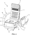
Figure 4 is a perspective view of the seat showing attachment of the arm rest panel to the seat structure; -
Figure 5 is a perspective view showing the right hand side arm rest shell assembly and arm rest shroud before assembly; -
Figure 6 is a perspective view showing installation of the left hand arm rest shell and shroud over the arm rest panel; and -
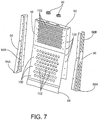
Figure 7 is a partial, exploded perspective view showing the back rest shell assembly. - Referring now specifically to the drawings, a
seat 10 according to an embodiment of the present invention is shown inFigures 1 and2 , and includes right hand and left hand arm rest assemblies12 and 14, aback rest assembly 16, ahead rest assembly 18, and aback rest beam 20. As shown inFigure 2 , thehead rest assembly 18 mounts to the top of theback rest assembly 16, and theback rest assembly 16 is positioned over theback rest beam 20. The right handarm rest assembly 12 slides down over a right handarm rest panel 22. In the same manner, the left handarm rest assembly 14 slides downwardly over a left handarm rest panel 48, as best shown inFigure 6 . -
Seat 10 also includes aseat pan 30 and aleg rest 32 mounted for selective movement between a retracted position, as shown, and an outward and upwardly-extended deployed use position. Theseat 10 includeslegs 34 adapted with feet for being attached to track fittings mounted into the deck of the aircraft. - Referring now to
Figure 3 , the right handarm rest panel 22 includes an armrest support plate 40 that is located at the top end of the right handarm rest panel 22 and extends laterally inwardly to provide weight-bearing support. Thearm rest panel 22 is fabricated of a flame-resistant meta-aramid material, such as sold by DuPont under the registered trademark Comex. Thearm rest panel 22 includesappropriate access holes 42 to receive fasteners, such asfasteners 44. - As shown in
Figure 4 , the left handarm rest panel 48 is mounted toseat frame 50 by attachment withfasteners 54 toarm rest braces 56 carried by theseat frame 50. The right handarm rest panel 22 is mounted to theseat frame 50 in the same manner. SeeFigure 2 . - Referring now to
Figures 2 and6 , thearm rest assembly 12 is formed from ashroud 60 and anarm rest support 70. Theshroud 60 includes apocket 62 for providing the seat occupant with a place to store a mobile phone or other electronics, magazines or small clothing or other personal items. Thearm rest support 70 is attached to thearm rest panel 22. Aflange 72 on the top of thearm rest support 70 supports the top of thearm rest shroud 60.Holes 74 are formed to provide weight reduction, and anopening 76 on the forward end of thearm rest support 70 permits installation of the seat controls. An opening 78 permits installation of push buttons to activate theseat pan 30,leg rest 32 andback rest 16 recline mechanisms. Tapered cut-outs arm rest support 70 are provided for ease of installation of theshroud 60 over thearm rest support 70. - After the right and left hand
arm rest panels frame 50, and the right and left hand arm rest assemblies 12 and 14 have been assembled as illustrated, the right handarm rest assembly 12, which includes theshroud 60, is mounted onto the right handarm rest support 70, as shown inFigure 6 . The right handarm rest assembly 12 is shown already in its use position, and the left armrest panel assembly 14 is shown as it is being lowered onto the left handarm rest panel 48. - The
back rest assembly 16 includes aback rest cover 90, and head rest guide andbezel 92, together with right hand and left handback rest frames Holes 98 are used to assemble with theback rest beam 20, which is part of theseat frame 50. Theback rest assembly 16 also includesrivet holes 100,weight reduction holes 102. Theback rest frames flanges Weight reduction holes back rest frames - A removable arm rest shroud for aircraft seating according to the invention have been described with reference to specific embodiments and examples. Various details of the invention may be changed without departing from the scope of the invention. Furthermore, the foregoing description of the preferred embodiments of the invention and best mode for practicing the invention are provided for the purpose of illustration only and not for the purpose of limitation, the invention being defined by the claims.
Claims (5)
- A passenger seat (10) comprising a seat bottom, a seat back (16, 20), a head rest (18) and a leg rest (32) mounted on a seat frame (50), and including:(a) a right hand arm rest panel (22) and a left hand arm rest panel (48) mounted to respective right and left hand sides of the seat frame;(b) a right hand arm rest assembly (12) positioned over the right hand arm rest panel (22), and a left hand arm rest assembly (14) positioned over the left hand arm rest panel (48); wherein(c) the right hand arm rest assembly (12) and the left hand arm rest assembly (14) includes an upholstered surface, andd) the right hand arm assembly (12) and the left hand arm assembly (14) are each comprised of an outer shroud (60) and an inner arm rest support (70) that are nested together to form a hollow structure that fits over respective right hand arm rest panel (22) and left hand arm rest panel,characterized in that the seat frame (50) includes a pair of outwardly-extending right hand arm rest braces and a pair of outwardly extending left hand arm rest braces (56), and the right hand inner arm rest support (70) and the left hand inner arm rest support each having attachment members adapted to cooperate with the respective arm rest braces to mount the right hand arm rest assembly and left hand arm rest assembly, and wherein the right hand and left hand arm rest braces (56) are vertically-oriented, and the attachment members comprise cut-outs (80, 82) in the right hand inner arm rest support (70) and left hand inner arm rest support that are adapted to fit over and be supported by the respective right hand and left hand arm rest braces.
- A seat according to claim 1 wherein the right hand arm rest panel and the left hand arm rest panel each include a support plate (40) positioned on an upper extent to support the respective right hand arm rest assembly and left hand arm rest assembly.
- A method of providing arm rests for passenger seats that are removable for repair or replacement, comprising the steps of:(a) providing a seat (10) according to any of claims 1-2;(b) the right hand arm rest assembly (12) and the left hand arm rest assembly (14) each comprised of an outer shroud (60) and an inner arm rest support (70) that are nested together to form a hollow structure;(c) providing an upholstery covering for the outer shrouds;(d) installing the right hand arm rest assembly (12) and the left hand arm rest assembly (14) over the respective right hand arm rest panel (22) and left hand arm rest panel (48), characterized in that the seat frame (50) includes a plurality of outwardly-extending right hand arm rest braces and a plurality of outwardly extending left hand arm rest braces (56), and the right hand inner arm rest support (70) and the left hand inner arm rest support each having attachment members adapted to cooperate with the respective arm rest braces to mount the right hand arm rest assembly (12) and left hand arm rest assembly (14), and wherein the right hand and left hand arm rest braces (56) are vertically-oriented, and the attachment members comprise cut-outs (80, 82) in the right hand inner arm rest support (70) and left hand inner arm rest support that are adapted to fit over and be supported by the respective right hand and left hand arm rest braces.
- A method according to claim 3, wherein the right hand arm rest panel and the left hand arm rest panel each include a support plate (40) positioned on an upper extent to support the respective a right hand arm rest assembly and left hand arm rest assembly.
- A method according to claim 3 or 4, and including the step of removing the right hand arm rest assembly (12) and left hand arm rest assembly (14) from the respective right hand arm rest panel (22) and the left hand arm rest panel (48) by lifting the right hand arm rest assembly and left hand arm rest assembly vertically upwardly from the respective right hand arm rest panel and the left hand arm rest panel.
Applications Claiming Priority (2)
| Application Number | Priority Date | Filing Date | Title |
|---|---|---|---|
| US201361893451P | 2013-10-21 | 2013-10-21 | |
| PCT/US2014/061580 WO2015061319A1 (en) | 2013-10-21 | 2014-10-21 | Arm rest shroud for aircraft |
Publications (3)
| Publication Number | Publication Date |
|---|---|
| EP3060476A1 EP3060476A1 (en) | 2016-08-31 |
| EP3060476A4 EP3060476A4 (en) | 2017-06-07 |
| EP3060476B1 true EP3060476B1 (en) | 2018-07-11 |
Family
ID=52825558
Family Applications (1)
| Application Number | Title | Priority Date | Filing Date |
|---|---|---|---|
| EP14855299.5A Active EP3060476B1 (en) | 2013-10-21 | 2014-10-21 | Arm rest shroud for aircraft |
Country Status (6)
| Country | Link |
|---|---|
| US (1) | US9758250B2 (en) |
| EP (1) | EP3060476B1 (en) |
| JP (1) | JP2016539837A (en) |
| CN (1) | CN105658521B (en) |
| CA (1) | CA2939986A1 (en) |
| WO (1) | WO2015061319A1 (en) |
Families Citing this family (4)
| Publication number | Priority date | Publication date | Assignee | Title |
|---|---|---|---|---|
| US10214291B2 (en) * | 2016-11-16 | 2019-02-26 | Ami Industries, Inc. | Energy absorbing assembly for a seat |
| US10829224B2 (en) | 2019-02-18 | 2020-11-10 | Goodrich Corporation | Easy hook armrest assembly for aircraft seat |
| US10925404B2 (en) * | 2019-04-01 | 2021-02-23 | La-Z-Boy Incorporated | Modular components for furniture members |
| US11147384B1 (en) * | 2020-09-30 | 2021-10-19 | Industrias Nortecaucanas S.A.S. | Dynamic privacy barrier system |
Family Cites Families (22)
| Publication number | Priority date | Publication date | Assignee | Title |
|---|---|---|---|---|
| US2174622A (en) * | 1937-06-24 | 1939-10-03 | Glenn L Martin Co | Aircraft furniture |
| US2802518A (en) * | 1952-12-23 | 1957-08-13 | T & C Aircraft Corp | Armrest construction |
| FR1586629A (en) * | 1968-01-17 | 1970-02-27 | ||
| US4027916A (en) * | 1975-12-15 | 1977-06-07 | Fairchild Industries Inc. | Seat armrest and process of manufacture thereof |
| JPS5426411U (en) * | 1977-07-25 | 1979-02-21 | ||
| US4264103A (en) * | 1979-04-30 | 1981-04-28 | Uop Inc. | Storable legrest assembly |
| US5800013A (en) * | 1989-06-15 | 1998-09-01 | Flight Equipment & Engineering Limited | Vehicle passenger seating |
| JPH03121126U (en) * | 1990-03-24 | 1991-12-11 | ||
| US5024486A (en) * | 1990-04-03 | 1991-06-18 | Auel Carl C | All-purpose rocking, swiveling, reclining, and lifting chair |
| US5352020A (en) | 1992-07-10 | 1994-10-04 | Weber Aircraft, Inc. | Hydraulic extendable legrest |
| US5584534A (en) * | 1992-11-16 | 1996-12-17 | Koito Industries Limited | Seat for disabled person |
| JPH0675252U (en) * | 1993-04-02 | 1994-10-25 | トヨタ車体株式会社 | Vehicle seat armrest fixing structure |
| US5658049A (en) * | 1995-10-19 | 1997-08-19 | Flexsteel Industries, Inc. | Separable recliner chair assembly |
| US5775778A (en) * | 1996-02-29 | 1998-07-07 | Prescient Partners, Lp | Shape adaptable and renewable furniture system |
| US5931535A (en) | 1998-01-30 | 1999-08-03 | Dacor Manufacturing Company, Inc. | Clinical care recliner |
| US6173921B1 (en) * | 1998-12-21 | 2001-01-16 | The Boeing Company | Airplane passenger privacy and support apparatus |
| JP3601776B2 (en) * | 2000-03-13 | 2004-12-15 | 小糸工業株式会社 | Aircraft seating equipment |
| JP3798934B2 (en) * | 2000-08-08 | 2006-07-19 | アロン化成株式会社 | Armrest mounting mechanism for portable toilet |
| US7011273B1 (en) * | 2003-03-19 | 2006-03-14 | Stanford Larry A | Organizer console |
| WO2009089167A1 (en) | 2008-01-05 | 2009-07-16 | Johnson Controls Technology Company | Entertainment seat |
| US8376462B2 (en) * | 2009-10-09 | 2013-02-19 | PAC Seating Systems, Inc. | Aircraft seat with adjustable armrests |
| CN202574242U (en) * | 2012-05-17 | 2012-12-05 | 浙江舜仕汽车技术有限公司 | Seat for high-speed train |
-
2014
- 2014-10-21 US US14/520,063 patent/US9758250B2/en active Active
- 2014-10-21 CN CN201480057785.4A patent/CN105658521B/en active Active
- 2014-10-21 EP EP14855299.5A patent/EP3060476B1/en active Active
- 2014-10-21 CA CA2939986A patent/CA2939986A1/en not_active Abandoned
- 2014-10-21 WO PCT/US2014/061580 patent/WO2015061319A1/en active Application Filing
- 2014-10-21 JP JP2016524401A patent/JP2016539837A/en active Pending
Non-Patent Citations (1)
| Title |
|---|
| None * |
Also Published As
| Publication number | Publication date |
|---|---|
| US20150108814A1 (en) | 2015-04-23 |
| CN105658521B (en) | 2018-05-11 |
| CN105658521A (en) | 2016-06-08 |
| CA2939986A1 (en) | 2015-04-30 |
| US9758250B2 (en) | 2017-09-12 |
| WO2015061319A1 (en) | 2015-04-30 |
| JP2016539837A (en) | 2016-12-22 |
| EP3060476A1 (en) | 2016-08-31 |
| EP3060476A4 (en) | 2017-06-07 |
Similar Documents
| Publication | Publication Date | Title |
|---|---|---|
| CA2992285C (en) | Recliner and legrest mechanism for a furniture member | |
| EP3060473B1 (en) | Independently articulating seat pan for aircraft seat | |
| CA2630000C (en) | Aircraft seating and seating arrangements | |
| EP3060476B1 (en) | Arm rest shroud for aircraft | |
| JP2016521157A (en) | Passenger seat with drop-down armrest assembly | |
| US20140246886A1 (en) | Aircraft divan convertible to a bunk bed | |
| CN110506004B (en) | Passenger seat with comfortable layout | |
| CA2987849C (en) | Transformable sofa | |
| GB2520812A (en) | Lift-recliner chair | |
| CA3045820C (en) | Folding chair with reduced footprint | |
| PL219906B1 (en) | System and method of fastening the seat and its accessories | |
| NZ568447A (en) | Aircraft seating and seating arrangements |
Legal Events
| Date | Code | Title | Description |
|---|---|---|---|
| PUAI | Public reference made under article 153(3) epc to a published international application that has entered the european phase |
Free format text: ORIGINAL CODE: 0009012 |
|
| 17P | Request for examination filed |
Effective date: 20160406 |
|
| AK | Designated contracting states |
Kind code of ref document: A1 Designated state(s): AL AT BE BG CH CY CZ DE DK EE ES FI FR GB GR HR HU IE IS IT LI LT LU LV MC MK MT NL NO PL PT RO RS SE SI SK SM TR |
|
| AX | Request for extension of the european patent |
Extension state: BA ME |
|
| DAX | Request for extension of the european patent (deleted) | ||
| A4 | Supplementary search report drawn up and despatched |
Effective date: 20170508 |
|
| RIC1 | Information provided on ipc code assigned before grant |
Ipc: B64D 11/06 20060101AFI20170428BHEP |
|
| GRAP | Despatch of communication of intention to grant a patent |
Free format text: ORIGINAL CODE: EPIDOSNIGR1 |
|
| INTG | Intention to grant announced |
Effective date: 20180208 |
|
| GRAS | Grant fee paid |
Free format text: ORIGINAL CODE: EPIDOSNIGR3 |
|
| GRAA | (expected) grant |
Free format text: ORIGINAL CODE: 0009210 |
|
| AK | Designated contracting states |
Kind code of ref document: B1 Designated state(s): AL AT BE BG CH CY CZ DE DK EE ES FI FR GB GR HR HU IE IS IT LI LT LU LV MC MK MT NL NO PL PT RO RS SE SI SK SM TR |
|
| REG | Reference to a national code |
Ref country code: GB Ref legal event code: FG4D |
|
| REG | Reference to a national code |
Ref country code: CH Ref legal event code: EP |
|
| REG | Reference to a national code |
Ref country code: AT Ref legal event code: REF Ref document number: 1016621 Country of ref document: AT Kind code of ref document: T Effective date: 20180715 |
|
| REG | Reference to a national code |
Ref country code: IE Ref legal event code: FG4D |
|
| REG | Reference to a national code |
Ref country code: DE Ref legal event code: R096 Ref document number: 602014028495 Country of ref document: DE |
|
| REG | Reference to a national code |
Ref country code: NL Ref legal event code: FP |
|
| REG | Reference to a national code |
Ref country code: FR Ref legal event code: PLFP Year of fee payment: 5 |
|
| REG | Reference to a national code |
Ref country code: LT Ref legal event code: MG4D |
|
| REG | Reference to a national code |
Ref country code: AT Ref legal event code: MK05 Ref document number: 1016621 Country of ref document: AT Kind code of ref document: T Effective date: 20180711 |
|
| PG25 | Lapsed in a contracting state [announced via postgrant information from national office to epo] |
Ref country code: AT Free format text: LAPSE BECAUSE OF FAILURE TO SUBMIT A TRANSLATION OF THE DESCRIPTION OR TO PAY THE FEE WITHIN THE PRESCRIBED TIME-LIMIT Effective date: 20180711 Ref country code: IS Free format text: LAPSE BECAUSE OF FAILURE TO SUBMIT A TRANSLATION OF THE DESCRIPTION OR TO PAY THE FEE WITHIN THE PRESCRIBED TIME-LIMIT Effective date: 20181111 Ref country code: BG Free format text: LAPSE BECAUSE OF FAILURE TO SUBMIT A TRANSLATION OF THE DESCRIPTION OR TO PAY THE FEE WITHIN THE PRESCRIBED TIME-LIMIT Effective date: 20181011 Ref country code: PL Free format text: LAPSE BECAUSE OF FAILURE TO SUBMIT A TRANSLATION OF THE DESCRIPTION OR TO PAY THE FEE WITHIN THE PRESCRIBED TIME-LIMIT Effective date: 20180711 Ref country code: SE Free format text: LAPSE BECAUSE OF FAILURE TO SUBMIT A TRANSLATION OF THE DESCRIPTION OR TO PAY THE FEE WITHIN THE PRESCRIBED TIME-LIMIT Effective date: 20180711 Ref country code: FI Free format text: LAPSE BECAUSE OF FAILURE TO SUBMIT A TRANSLATION OF THE DESCRIPTION OR TO PAY THE FEE WITHIN THE PRESCRIBED TIME-LIMIT Effective date: 20180711 Ref country code: NO Free format text: LAPSE BECAUSE OF FAILURE TO SUBMIT A TRANSLATION OF THE DESCRIPTION OR TO PAY THE FEE WITHIN THE PRESCRIBED TIME-LIMIT Effective date: 20181011 Ref country code: RS Free format text: LAPSE BECAUSE OF FAILURE TO SUBMIT A TRANSLATION OF THE DESCRIPTION OR TO PAY THE FEE WITHIN THE PRESCRIBED TIME-LIMIT Effective date: 20180711 Ref country code: GR Free format text: LAPSE BECAUSE OF FAILURE TO SUBMIT A TRANSLATION OF THE DESCRIPTION OR TO PAY THE FEE WITHIN THE PRESCRIBED TIME-LIMIT Effective date: 20181012 Ref country code: LT Free format text: LAPSE BECAUSE OF FAILURE TO SUBMIT A TRANSLATION OF THE DESCRIPTION OR TO PAY THE FEE WITHIN THE PRESCRIBED TIME-LIMIT Effective date: 20180711 |
|
| PG25 | Lapsed in a contracting state [announced via postgrant information from national office to epo] |
Ref country code: HR Free format text: LAPSE BECAUSE OF FAILURE TO SUBMIT A TRANSLATION OF THE DESCRIPTION OR TO PAY THE FEE WITHIN THE PRESCRIBED TIME-LIMIT Effective date: 20180711 Ref country code: AL Free format text: LAPSE BECAUSE OF FAILURE TO SUBMIT A TRANSLATION OF THE DESCRIPTION OR TO PAY THE FEE WITHIN THE PRESCRIBED TIME-LIMIT Effective date: 20180711 Ref country code: LV Free format text: LAPSE BECAUSE OF FAILURE TO SUBMIT A TRANSLATION OF THE DESCRIPTION OR TO PAY THE FEE WITHIN THE PRESCRIBED TIME-LIMIT Effective date: 20180711 |
|
| REG | Reference to a national code |
Ref country code: DE Ref legal event code: R097 Ref document number: 602014028495 Country of ref document: DE |
|
| PG25 | Lapsed in a contracting state [announced via postgrant information from national office to epo] |
Ref country code: IT Free format text: LAPSE BECAUSE OF FAILURE TO SUBMIT A TRANSLATION OF THE DESCRIPTION OR TO PAY THE FEE WITHIN THE PRESCRIBED TIME-LIMIT Effective date: 20180711 Ref country code: CZ Free format text: LAPSE BECAUSE OF FAILURE TO SUBMIT A TRANSLATION OF THE DESCRIPTION OR TO PAY THE FEE WITHIN THE PRESCRIBED TIME-LIMIT Effective date: 20180711 Ref country code: RO Free format text: LAPSE BECAUSE OF FAILURE TO SUBMIT A TRANSLATION OF THE DESCRIPTION OR TO PAY THE FEE WITHIN THE PRESCRIBED TIME-LIMIT Effective date: 20180711 Ref country code: ES Free format text: LAPSE BECAUSE OF FAILURE TO SUBMIT A TRANSLATION OF THE DESCRIPTION OR TO PAY THE FEE WITHIN THE PRESCRIBED TIME-LIMIT Effective date: 20180711 Ref country code: EE Free format text: LAPSE BECAUSE OF FAILURE TO SUBMIT A TRANSLATION OF THE DESCRIPTION OR TO PAY THE FEE WITHIN THE PRESCRIBED TIME-LIMIT Effective date: 20180711 |
|
| PLBE | No opposition filed within time limit |
Free format text: ORIGINAL CODE: 0009261 |
|
| STAA | Information on the status of an ep patent application or granted ep patent |
Free format text: STATUS: NO OPPOSITION FILED WITHIN TIME LIMIT |
|
| PG25 | Lapsed in a contracting state [announced via postgrant information from national office to epo] |
Ref country code: DK Free format text: LAPSE BECAUSE OF FAILURE TO SUBMIT A TRANSLATION OF THE DESCRIPTION OR TO PAY THE FEE WITHIN THE PRESCRIBED TIME-LIMIT Effective date: 20180711 Ref country code: SM Free format text: LAPSE BECAUSE OF FAILURE TO SUBMIT A TRANSLATION OF THE DESCRIPTION OR TO PAY THE FEE WITHIN THE PRESCRIBED TIME-LIMIT Effective date: 20180711 Ref country code: SK Free format text: LAPSE BECAUSE OF FAILURE TO SUBMIT A TRANSLATION OF THE DESCRIPTION OR TO PAY THE FEE WITHIN THE PRESCRIBED TIME-LIMIT Effective date: 20180711 |
|
| REG | Reference to a national code |
Ref country code: CH Ref legal event code: PL |
|
| 26N | No opposition filed |
Effective date: 20190412 |
|
| REG | Reference to a national code |
Ref country code: BE Ref legal event code: MM Effective date: 20181031 |
|
| PG25 | Lapsed in a contracting state [announced via postgrant information from national office to epo] |
Ref country code: LU Free format text: LAPSE BECAUSE OF NON-PAYMENT OF DUE FEES Effective date: 20181021 Ref country code: MC Free format text: LAPSE BECAUSE OF FAILURE TO SUBMIT A TRANSLATION OF THE DESCRIPTION OR TO PAY THE FEE WITHIN THE PRESCRIBED TIME-LIMIT Effective date: 20180711 |
|
| REG | Reference to a national code |
Ref country code: IE Ref legal event code: MM4A |
|
| PG25 | Lapsed in a contracting state [announced via postgrant information from national office to epo] |
Ref country code: CH Free format text: LAPSE BECAUSE OF NON-PAYMENT OF DUE FEES Effective date: 20181031 Ref country code: LI Free format text: LAPSE BECAUSE OF NON-PAYMENT OF DUE FEES Effective date: 20181031 Ref country code: SI Free format text: LAPSE BECAUSE OF FAILURE TO SUBMIT A TRANSLATION OF THE DESCRIPTION OR TO PAY THE FEE WITHIN THE PRESCRIBED TIME-LIMIT Effective date: 20180711 Ref country code: BE Free format text: LAPSE BECAUSE OF NON-PAYMENT OF DUE FEES Effective date: 20181031 |
|
| PG25 | Lapsed in a contracting state [announced via postgrant information from national office to epo] |
Ref country code: IE Free format text: LAPSE BECAUSE OF NON-PAYMENT OF DUE FEES Effective date: 20181021 |
|
| PG25 | Lapsed in a contracting state [announced via postgrant information from national office to epo] |
Ref country code: MT Free format text: LAPSE BECAUSE OF NON-PAYMENT OF DUE FEES Effective date: 20181021 |
|
| PG25 | Lapsed in a contracting state [announced via postgrant information from national office to epo] |
Ref country code: TR Free format text: LAPSE BECAUSE OF FAILURE TO SUBMIT A TRANSLATION OF THE DESCRIPTION OR TO PAY THE FEE WITHIN THE PRESCRIBED TIME-LIMIT Effective date: 20180711 |
|
| PG25 | Lapsed in a contracting state [announced via postgrant information from national office to epo] |
Ref country code: PT Free format text: LAPSE BECAUSE OF FAILURE TO SUBMIT A TRANSLATION OF THE DESCRIPTION OR TO PAY THE FEE WITHIN THE PRESCRIBED TIME-LIMIT Effective date: 20180711 |
|
| PG25 | Lapsed in a contracting state [announced via postgrant information from national office to epo] |
Ref country code: HU Free format text: LAPSE BECAUSE OF FAILURE TO SUBMIT A TRANSLATION OF THE DESCRIPTION OR TO PAY THE FEE WITHIN THE PRESCRIBED TIME-LIMIT; INVALID AB INITIO Effective date: 20141021 Ref country code: MK Free format text: LAPSE BECAUSE OF NON-PAYMENT OF DUE FEES Effective date: 20180711 Ref country code: CY Free format text: LAPSE BECAUSE OF FAILURE TO SUBMIT A TRANSLATION OF THE DESCRIPTION OR TO PAY THE FEE WITHIN THE PRESCRIBED TIME-LIMIT Effective date: 20180711 |
|
| PGFP | Annual fee paid to national office [announced via postgrant information from national office to epo] |
Ref country code: NL Payment date: 20230922 Year of fee payment: 10 Ref country code: GB Payment date: 20230920 Year of fee payment: 10 |
|
| PGFP | Annual fee paid to national office [announced via postgrant information from national office to epo] |
Ref country code: FR Payment date: 20230920 Year of fee payment: 10 |
|
| PGFP | Annual fee paid to national office [announced via postgrant information from national office to epo] |
Ref country code: DE Payment date: 20230920 Year of fee payment: 10 |