EP3060137B1 - Transseptal crossing needle device - Google Patents
Transseptal crossing needle device Download PDFInfo
- Publication number
- EP3060137B1 EP3060137B1 EP14854910.8A EP14854910A EP3060137B1 EP 3060137 B1 EP3060137 B1 EP 3060137B1 EP 14854910 A EP14854910 A EP 14854910A EP 3060137 B1 EP3060137 B1 EP 3060137B1
- Authority
- EP
- European Patent Office
- Prior art keywords
- needle
- sheath
- tip
- handle
- gap
- Prior art date
- Legal status (The legal status is an assumption and is not a legal conclusion. Google has not performed a legal analysis and makes no representation as to the accuracy of the status listed.)
- Active
Links
Images


Classifications
-
- A—HUMAN NECESSITIES
- A61—MEDICAL OR VETERINARY SCIENCE; HYGIENE
- A61B—DIAGNOSIS; SURGERY; IDENTIFICATION
- A61B17/00—Surgical instruments, devices or methods
- A61B17/34—Trocars; Puncturing needles
- A61B17/3478—Endoscopic needles, e.g. for infusion
-
- A—HUMAN NECESSITIES
- A61—MEDICAL OR VETERINARY SCIENCE; HYGIENE
- A61B—DIAGNOSIS; SURGERY; IDENTIFICATION
- A61B17/00—Surgical instruments, devices or methods
- A61B17/34—Trocars; Puncturing needles
- A61B17/3403—Needle locating or guiding means
-
- A—HUMAN NECESSITIES
- A61—MEDICAL OR VETERINARY SCIENCE; HYGIENE
- A61B—DIAGNOSIS; SURGERY; IDENTIFICATION
- A61B17/00—Surgical instruments, devices or methods
- A61B17/00234—Surgical instruments, devices or methods for minimally invasive surgery
- A61B2017/00238—Type of minimally invasive operation
- A61B2017/00243—Type of minimally invasive operation cardiac
- A61B2017/00247—Making holes in the wall of the heart, e.g. laser Myocardial revascularization
-
- A—HUMAN NECESSITIES
- A61—MEDICAL OR VETERINARY SCIENCE; HYGIENE
- A61B—DIAGNOSIS; SURGERY; IDENTIFICATION
- A61B17/00—Surgical instruments, devices or methods
- A61B17/00234—Surgical instruments, devices or methods for minimally invasive surgery
- A61B2017/00292—Surgical instruments, devices or methods for minimally invasive surgery mounted on or guided by flexible, e.g. catheter-like, means
- A61B2017/00336—Surgical instruments, devices or methods for minimally invasive surgery mounted on or guided by flexible, e.g. catheter-like, means with a protective sleeve, e.g. retractable or slidable
-
- A—HUMAN NECESSITIES
- A61—MEDICAL OR VETERINARY SCIENCE; HYGIENE
- A61B—DIAGNOSIS; SURGERY; IDENTIFICATION
- A61B17/00—Surgical instruments, devices or methods
- A61B17/34—Trocars; Puncturing needles
- A61B17/3403—Needle locating or guiding means
- A61B2017/3413—Needle locating or guiding means guided by ultrasound
-
- A—HUMAN NECESSITIES
- A61—MEDICAL OR VETERINARY SCIENCE; HYGIENE
- A61B—DIAGNOSIS; SURGERY; IDENTIFICATION
- A61B90/00—Instruments, implements or accessories specially adapted for surgery or diagnosis and not covered by any of the groups A61B1/00 - A61B50/00, e.g. for luxation treatment or for protecting wound edges
- A61B90/06—Measuring instruments not otherwise provided for
- A61B2090/062—Measuring instruments not otherwise provided for penetration depth
-
- A—HUMAN NECESSITIES
- A61—MEDICAL OR VETERINARY SCIENCE; HYGIENE
- A61B—DIAGNOSIS; SURGERY; IDENTIFICATION
- A61B90/00—Instruments, implements or accessories specially adapted for surgery or diagnosis and not covered by any of the groups A61B1/00 - A61B50/00, e.g. for luxation treatment or for protecting wound edges
- A61B90/08—Accessories or related features not otherwise provided for
- A61B2090/0807—Indication means
- A61B2090/0811—Indication means for the position of a particular part of an instrument with respect to the rest of the instrument, e.g. position of the anvil of a stapling instrument
-
- A—HUMAN NECESSITIES
- A61—MEDICAL OR VETERINARY SCIENCE; HYGIENE
- A61B—DIAGNOSIS; SURGERY; IDENTIFICATION
- A61B90/00—Instruments, implements or accessories specially adapted for surgery or diagnosis and not covered by any of the groups A61B1/00 - A61B50/00, e.g. for luxation treatment or for protecting wound edges
- A61B90/39—Markers, e.g. radio-opaque or breast lesions markers
- A61B2090/3925—Markers, e.g. radio-opaque or breast lesions markers ultrasonic
-
- A—HUMAN NECESSITIES
- A61—MEDICAL OR VETERINARY SCIENCE; HYGIENE
- A61B—DIAGNOSIS; SURGERY; IDENTIFICATION
- A61B90/00—Instruments, implements or accessories specially adapted for surgery or diagnosis and not covered by any of the groups A61B1/00 - A61B50/00, e.g. for luxation treatment or for protecting wound edges
- A61B90/39—Markers, e.g. radio-opaque or breast lesions markers
- A61B2090/3966—Radiopaque markers visible in an X-ray image
-
- A—HUMAN NECESSITIES
- A61—MEDICAL OR VETERINARY SCIENCE; HYGIENE
- A61M—DEVICES FOR INTRODUCING MEDIA INTO, OR ONTO, THE BODY; DEVICES FOR TRANSDUCING BODY MEDIA OR FOR TAKING MEDIA FROM THE BODY; DEVICES FOR PRODUCING OR ENDING SLEEP OR STUPOR
- A61M25/00—Catheters; Hollow probes
- A61M25/0067—Catheters; Hollow probes characterised by the distal end, e.g. tips
- A61M25/0082—Catheter tip comprising a tool
- A61M25/0084—Catheter tip comprising a tool being one or more injection needles
- A61M2025/0089—Single injection needle protruding axially, i.e. along the longitudinal axis of the catheter, from the distal tip
-
- A—HUMAN NECESSITIES
- A61—MEDICAL OR VETERINARY SCIENCE; HYGIENE
- A61M—DEVICES FOR INTRODUCING MEDIA INTO, OR ONTO, THE BODY; DEVICES FOR TRANSDUCING BODY MEDIA OR FOR TAKING MEDIA FROM THE BODY; DEVICES FOR PRODUCING OR ENDING SLEEP OR STUPOR
- A61M25/00—Catheters; Hollow probes
- A61M25/01—Introducing, guiding, advancing, emplacing or holding catheters
- A61M25/06—Body-piercing guide needles or the like
- A61M25/0662—Guide tubes
- A61M2025/0681—Systems with catheter and outer tubing, e.g. sheath, sleeve or guide tube
-
- A—HUMAN NECESSITIES
- A61—MEDICAL OR VETERINARY SCIENCE; HYGIENE
- A61M—DEVICES FOR INTRODUCING MEDIA INTO, OR ONTO, THE BODY; DEVICES FOR TRANSDUCING BODY MEDIA OR FOR TAKING MEDIA FROM THE BODY; DEVICES FOR PRODUCING OR ENDING SLEEP OR STUPOR
- A61M25/00—Catheters; Hollow probes
- A61M25/0021—Catheters; Hollow probes characterised by the form of the tubing
- A61M25/0041—Catheters; Hollow probes characterised by the form of the tubing pre-formed, e.g. specially adapted to fit with the anatomy of body channels
-
- A—HUMAN NECESSITIES
- A61—MEDICAL OR VETERINARY SCIENCE; HYGIENE
- A61M—DEVICES FOR INTRODUCING MEDIA INTO, OR ONTO, THE BODY; DEVICES FOR TRANSDUCING BODY MEDIA OR FOR TAKING MEDIA FROM THE BODY; DEVICES FOR PRODUCING OR ENDING SLEEP OR STUPOR
- A61M25/00—Catheters; Hollow probes
- A61M25/01—Introducing, guiding, advancing, emplacing or holding catheters
- A61M25/0105—Steering means as part of the catheter or advancing means; Markers for positioning
- A61M25/0133—Tip steering devices
- A61M25/0152—Tip steering devices with pre-shaped mechanisms, e.g. pre-shaped stylets or pre-shaped outer tubes
-
- A—HUMAN NECESSITIES
- A61—MEDICAL OR VETERINARY SCIENCE; HYGIENE
- A61M—DEVICES FOR INTRODUCING MEDIA INTO, OR ONTO, THE BODY; DEVICES FOR TRANSDUCING BODY MEDIA OR FOR TAKING MEDIA FROM THE BODY; DEVICES FOR PRODUCING OR ENDING SLEEP OR STUPOR
- A61M25/00—Catheters; Hollow probes
- A61M25/01—Introducing, guiding, advancing, emplacing or holding catheters
- A61M25/06—Body-piercing guide needles or the like
-
- A—HUMAN NECESSITIES
- A61—MEDICAL OR VETERINARY SCIENCE; HYGIENE
- A61M—DEVICES FOR INTRODUCING MEDIA INTO, OR ONTO, THE BODY; DEVICES FOR TRANSDUCING BODY MEDIA OR FOR TAKING MEDIA FROM THE BODY; DEVICES FOR PRODUCING OR ENDING SLEEP OR STUPOR
- A61M29/00—Dilators with or without means for introducing media, e.g. remedies
Definitions
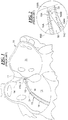
- Transseptal crossing, puncture, or catheterization is a means of gaining access to the left atrium 11 from the right atrium 12 of the heart 10. These chambers of the heart are shown in prior art Fig. 1 but since the patient is being viewed from the front, the left atrium 11 is shown on the right side and the right atrium 12 is shown on the left side in the drawing figure.
- This transseptal crossing, puncture, or catheterization was first described independently by Ross and Cope in 1959 in the article " Transseptal Catheterization in 2010: Crossing into a New Decade", EP Lab Digest, February 2010 . In Fig.
- a transseptal crossing needle device 13 having an outer sheath 14, an inner dilator sheath 15, and a hollow needle 16 positioned within the inner sheath 15.
- the needle 16 has a curved portion 24 progressing towards a tip portion 16A.
- the inner sheath 15, as most clearly shown in expanded prior art view Fig. 2 has a partial conical tip tapering portion 15A and also is curved near it's end by the forces exerted by the needle curved portion 24.
- the hollow needle 16 has a transverse cut tip portion 16A terminating in a tip 16AB at the end of upwardly sloping transverse end surface 16AA.
- this surface 16AA slopes towards an upper concave curved inner wall 15B of the end portion of the inner sheath 15 and away from a lower convex curved inner wall 15A.
- AF atrial fibrillation
- new minimally invasive percutaneous procedures related to structural heart are also being developed that use these devices. These procedures include the closure of atrial septal defects, left atrial appendage closure device implementation, and left ventricular assist device implantation.
- Transseptal crossing across what is known as the septum 17 (fossa ovalis) as shown in Fig. 1 to gain access to the left atrium 11 is acknowledged as a critical and very dangerous part of all of the above procedures.
- Clinical guidelines support the use of multiple visualization checks when conducting this procedure with many physicians using a combination of fluoroscopy, echocardiography, pacing, and contrast injection, along with their own judgment and experience.
- access to the left atrium 11 via the septum 14 (fossa ovalis) as described above is required. These procedures include mitral valve repair, mitral valvoplasty, atrial fibrillation ablation, and closure of left atrial appendage repair or closure.
- Prior art US 2006/0064062 A1 discloses a known transseptal puncture needle.
- the tapered conical end portion 15A of the inner dilator sheath 15, and more particularly the leading end 15AA, is moved down the septum 17 as shown by the arrow 18 until it reaches the relatively thinnest part of the septum 17. Thereafter the hollow needle 16 is pushed beyond the inner sheath end 15AA and penetrates through the septum 17. Thereafter the inner sheath 15 functioning as a dilator dilates with its conical end portion 15A the opening provided by the needle and pushes through, thus dilated the needle opening. Thereafter the outer sheath 14 is pushed along the inner sheath 15 through the dilated opening 17A. As shown in Fig. 4 , the needle 16 and inner dilator sheath 15 are then withdrawn, leaving only the outer sheath 14 in the opening 17A, which is then available for use with medical instrumentation to be inserted into the left atrium 11 as described above.
- the tip portion 16A of the needle 16 penetrates the septum 14 using ultrasound visualization.
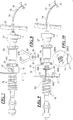
- FIG. 3 illustrates how the physician manipulates the inner and outer sheaths 15 and 14, and needle 16, for the above-described procedure.
- the needle 16 is pushed through the inner dilator sheath 15 until the tip portion 16A with tip 16AB is positioned near the tapered end portion 15A as shown in Fig. 2 .
- a needle handle 19 firmly attached to an end of the hollow needle 16 is provided for manipulating the needle through the inner sheath 15.
- the needle handle 19 has a plurality of finger grip knurls 20.
- a leading end of the handle 19 has a pointing arrow 21 to indicate a rotational position of the needle 16, and particularly of the needle curved portion 24 leading to the tip portion 16A at the end of the hollow needle 16.
- the steel needle is pre-stressed into a curve at the curved portion 24 which causes a bending of the flexible inner sheath 15 and outer sheath 14 where the needle curved portion 24 is present.
- a stop cock 22 for allowing in flow a liquid such as a dye introduced through a flexible hose 23 for delivery through the needle.
- the needle 16 passes through an inner dilator sheath handle 26 firmly attached to the inner dilator sheath 15.
- a knurled finger grip 26A is integrally formed at the needle entry end of the inner sheath handle 26 for finger gripping.
- the opposite end of the inner sheath handle 26 butts against an outer sheath handle 27 having a knurled finger grip portion 27A.
- the outer sheath handle 27 is rigidly attached to the end of the outer sheath 14 for manipulation thereof.
- a hose 27B allows introduction of a fluid such as saline solution into the outer sheath 14 which surrounds the inner sheath 15.
- the outer sheath 14 with the inner sheath 15 and needle 16 enter an outer wall of the human body 28 as shown at 28A and then are fed up to the heart through an artery, for example, and then to the septum 17 within the heart as explained in connection with Fig. 1 so as to create the desired diluted aperture 17A in the septum 17 as described above.
- the physician pushes on the needle handle 19 to close the gap G between the leading end at arrow 21 of the handle 19 and the back surface of the inner sheath dilator handle 26.
- This causes the tip 16A of the needle to push out through the end 15AA of the inner sheath 15A to penetrate through the septum 17 such that thereafter a small portion of the needle at it's tip portion now lies on the opposite side of the septum within the left ventricle 11.
- shavings 29 can be scraped off by skiving at the upper convex curved inner wall 15B of the inner sheath 15 by the tip 16AB running along this convex curved inner wall 15B. This is undesirable and a disadvantage of this prior art device.
- a transseptal crossing needle device for inserting an outer sheath through a septum, an inner dilator sheath is received within the outer sheath and a needle having a curved end portion adjacent a tip of a tip portion of the needle is provided, the needle being received in the inner dilator sheath.
- the needle tip portion comprises an angled transverse end surface terminating at said tip and slanting away from an inner concave curved wall of said inner sheath curved by the needle curved end portion, the needle tip being spaced not only away from said inner concave curved wall of said inner sheath but also away from an inner convex curved wall of said inner sheath concave wall to reduce or eliminate skiving of material from the concave and convex inner walls of the inner sheath.
- the improved tip portion 29 has its transverse end surface 29A downwardly sloping towards the convex curved inner wall 15C of sheath 15 as it proceeds to the tip 29AB.
- This slope is opposite to the slope of the prior art tip portion 16A which slopes upwardly towards the concave inner wall 15B of the sheath.
- skiving is prevented at the curved portion 24 of the needle and inner and outer sheaths.
- first and second echogenic markers 30 and 31 which allow the physician to visualize by ultrasound a location of the tip 29AB at improved tip portion 29 and also the amount of the needle 16 which has been pushed and penetrated through the septum 17 by use of the marker 31 just beginning to emerge from the hole 17A in the septum 17.
- the first echogenic marker 30 is also shown in Fig. 5 .
- These echogenic markers 30 and 31 are also shown in enlarged view in Fig. 12 along with the improved tip portion 29.
- the first echogenic marker 30 at the improved tip portion 29 can have a length of approximately 1-2mm.
- the second echogenic marker 31 can extend for 1-5mm, for example, and can be located between 5-30mm from the needle tip 29AB as shown in Figs. 6 and 12 .
- the second marker 31 can be used for additional visualization during delivery of the needle.
- these markers 30 and 31 are useful for the user since the echo ultrasound is a 2D medium whereas the device is used in 3D space. This can translate and be used into characterizing the angulation of the improved needle tip portion 29.
- the visualization for the echogenic markers 30 and 31 is achieved by a surface texturing which can be accomplished in a number of ways including sand or grit blasting, laser ablation of the metal surface, grinding or mechanically modifying the outer surface of the needle.
- the transverse end surface 29A is achieved by cutting or grinding a metal hypo tube of which the needle is constructed (for example stainless steel, cobalt, chrome alloy, nitinol).
- This angled tip portion is created by grinding, for example, at the distal end.
- the angled tip portion minimizes skiving (cutting off of thin layers of the material from the convex 15C or concave 15B curved inside walls of the dilator inner sheath 15 during insertion of the needle). This plastic material, if dislodged, could enter the vascular system and cause a blockage.
- FIG. 8 a first embodiment spacer device is shown at 35 and in an end view in Fig. 8 .
- This spacer device 35 comprises a springly metal or plastic clip having a split tubular section 36 split at 36A with clip ears 37A and 37B which are pressed together by the user's fingers to open the springy clip for placement around the hollow needle 16 in the gap G previously described in prior art Fig. 3 .
- FIG. 9 A second embodiment spacer device 38 in an improved transseptal needle device 33, is shown in Figs. 9 and 10 .
- This spacer device 38 has a handle portion 38A and a split collar section 38B received by friction fit in a circular slot 39 in an improvement to the prior art handle 19.
- a gap G' greater than the gap G is provided wherein the physician or user sets the insertion distance of the split collar section 38B to same gap G described above in connection with prior art Fig. 3 . Then when the user pushes on the handle 19 the gap G is closed off so that a new gap G'-G results due to the longitudinal extent of the handle portion 38A. This also achieves safe positioning of the needle tip as previously described.
- Fig. 10 shows an end view looking towards the pointer 21 of the handle 19 and illustrates the collar sloped circular slot 39 for receiving the two split collar sections 38BA and 38BB of the split collar 38B.
- Fig. 11 shows a further improved transseptal crossing device 34 according to a third embodiment for spacing and which is used instead of the spacer devices 35 shown in Fig. 7 and 38 in Fig. 9 .
- first and second visual markers 40 and 41 are provided located in gap G in prior art Fig. 3 .
- These visual markers 40 and 41 on the needle 16 are, for example, printed on the needle 16 shaft as shown in Fig. 11 .
- the first marker 40 is used relative to the end surface 26AA of the knurled portion 26A of the dilator inner sheath handle 26. This first marker 40 identifies when the tip 29AB of the needle is approximately 2-3cm from the opening at the end 15AA of the inner dilator sheath 15.
- the second visual marker 41 indicates when the tip 29AB is about to exit the distal end of the dilator inner sheath 15 such as shown in Fig. 5 .
- the first and second markers 40 and 41 can be printed using luminous ink to make them highly visible in dimly lit catheterization labs. These visual markers 40 and 41 are particularly effective for inexperienced users as they become familiar with the procedure and the equipment.
Landscapes
- Health & Medical Sciences (AREA)
- Surgery (AREA)
- Life Sciences & Earth Sciences (AREA)
- Biomedical Technology (AREA)
- Nuclear Medicine, Radiotherapy & Molecular Imaging (AREA)
- Engineering & Computer Science (AREA)
- Pathology (AREA)
- Heart & Thoracic Surgery (AREA)
- Medical Informatics (AREA)
- Molecular Biology (AREA)
- Animal Behavior & Ethology (AREA)
- General Health & Medical Sciences (AREA)
- Public Health (AREA)
- Veterinary Medicine (AREA)
- Surgical Instruments (AREA)
Description
- Transseptal crossing, puncture, or catheterization is a means of gaining access to the
left atrium 11 from theright atrium 12 of theheart 10. These chambers of the heart are shown in prior artFig. 1 but since the patient is being viewed from the front, theleft atrium 11 is shown on the right side and theright atrium 12 is shown on the left side in the drawing figure. This transseptal crossing, puncture, or catheterization was first described independently by Ross and Cope in 1959 in the article "Transseptal Catheterization in 2010: Crossing into a New Decade", EP Lab Digest, February 2010. InFig. 1 one may observe a transseptalcrossing needle device 13 having anouter sheath 14, aninner dilator sheath 15, and ahollow needle 16 positioned within theinner sheath 15. Theneedle 16 has acurved portion 24 progressing towards atip portion 16A. Theinner sheath 15, as most clearly shown in expanded prior art viewFig. 2 , has a partial conicaltip tapering portion 15A and also is curved near it's end by the forces exerted by the needle curvedportion 24. Thehollow needle 16 has a transversecut tip portion 16A terminating in a tip 16AB at the end of upwardly sloping transverse end surface 16AA. Note that this surface 16AA slopes towards an upper concave curvedinner wall 15B of the end portion of theinner sheath 15 and away from a lower convex curvedinner wall 15A. Over the past 10 years or so, the number of transseptal crossings being performed has increased dramatically, driven mostly by the increase in atrial fibrillation (AF) ablation procedures within electrophysiology. This remains the predominant use of transseptal crossing devices. However, new minimally invasive percutaneous procedures related to structural heart are also being developed that use these devices. These procedures include the closure of atrial septal defects, left atrial appendage closure device implementation, and left ventricular assist device implantation. - Transseptal crossing across what is known as the septum 17 (fossa ovalis) as shown in
Fig. 1 to gain access to theleft atrium 11 is acknowledged as a critical and very dangerous part of all of the above procedures. Clinical guidelines support the use of multiple visualization checks when conducting this procedure with many physicians using a combination of fluoroscopy, echocardiography, pacing, and contrast injection, along with their own judgment and experience. For a number of different procedures, access to theleft atrium 11 via the septum 14 (fossa ovalis) as described above is required. These procedures include mitral valve repair, mitral valvoplasty, atrial fibrillation ablation, and closure of left atrial appendage repair or closure. Prior artUS 2006/0064062 A1 discloses a known transseptal puncture needle. - Referring to
Fig. 1 , according to the prior art procedure the taperedconical end portion 15A of theinner dilator sheath 15, and more particularly the leading end 15AA, is moved down theseptum 17 as shown by thearrow 18 until it reaches the relatively thinnest part of theseptum 17. Thereafter thehollow needle 16 is pushed beyond the inner sheath end 15AA and penetrates through theseptum 17. Thereafter theinner sheath 15 functioning as a dilator dilates with itsconical end portion 15A the opening provided by the needle and pushes through, thus dilated the needle opening. Thereafter theouter sheath 14 is pushed along theinner sheath 15 through thedilated opening 17A. As shown inFig. 4 , theneedle 16 andinner dilator sheath 15 are then withdrawn, leaving only theouter sheath 14 in the opening 17A, which is then available for use with medical instrumentation to be inserted into theleft atrium 11 as described above. - The
tip portion 16A of theneedle 16 penetrates theseptum 14 using ultrasound visualization. - Prior art
Fig. 3 illustrates how the physician manipulates the inner andouter sheaths needle 16, for the above-described procedure. Initially before introduction into the human body, theneedle 16 is pushed through theinner dilator sheath 15 until thetip portion 16A with tip 16AB is positioned near thetapered end portion 15A as shown inFig. 2 . Aneedle handle 19 firmly attached to an end of thehollow needle 16 is provided for manipulating the needle through theinner sheath 15. Theneedle handle 19 has a plurality offinger grip knurls 20. A leading end of thehandle 19 has a pointingarrow 21 to indicate a rotational position of theneedle 16, and particularly of the needle curvedportion 24 leading to thetip portion 16A at the end of thehollow needle 16. The steel needle is pre-stressed into a curve at thecurved portion 24 which causes a bending of the flexibleinner sheath 15 andouter sheath 14 where the needle curvedportion 24 is present. - Rearwardly of the
finger knurls 20 is located astop cock 22 for allowing in flow a liquid such as a dye introduced through aflexible hose 23 for delivery through the needle. - As illustrated in
Fig. 3 , theneedle 16 passes through an innerdilator sheath handle 26 firmly attached to theinner dilator sheath 15. A knurledfinger grip 26A is integrally formed at the needle entry end of theinner sheath handle 26 for finger gripping. - The opposite end of the inner sheath handle 26 butts against an
outer sheath handle 27 having a knurledfinger grip portion 27A. Theouter sheath handle 27 is rigidly attached to the end of theouter sheath 14 for manipulation thereof. Ahose 27B allows introduction of a fluid such as saline solution into theouter sheath 14 which surrounds theinner sheath 15. - The
outer sheath 14 with theinner sheath 15 andneedle 16 enter an outer wall of thehuman body 28 as shown at 28A and then are fed up to the heart through an artery, for example, and then to theseptum 17 within the heart as explained in connection withFig. 1 so as to create the desired dilutedaperture 17A in theseptum 17 as described above. - After the
conical portion 16A of theinner dilator sheath 16 has been located as described above at theseptum 17 inFig. 1 , then the physician pushes on theneedle handle 19 to close the gap G between the leading end atarrow 21 of thehandle 19 and the back surface of the innersheath dilator handle 26. This causes thetip 16A of the needle to push out through the end 15AA of theinner sheath 15A to penetrate through theseptum 17 such that thereafter a small portion of the needle at it's tip portion now lies on the opposite side of the septum within theleft ventricle 11. - During introduction and movement of the
tip portion 16A having the transverse upwardly slanting angled end surface 16AA as shown inFig. 2 to form the tip 16AB,shavings 29 can be scraped off by skiving at the upper convex curvedinner wall 15B of theinner sheath 15 by the tip 16AB running along this convex curvedinner wall 15B. This is undesirable and a disadvantage of this prior art device. - Another disadvantage of the prior art system is that presently the skill of the operator and "feel" are critical determining factors in the successful placement of the
needle 16 and crossing of thefossa 14. Significant training is required in order for a physician to complete this procedure correctly. - It is an objective to eliminate the creation of shavings by the above-described skimming and also to provide improved safety and ease of delivery of the needle of the transseptal crossing needle device for penetration of the septum as described above.
- In a transseptal crossing needle device for inserting an outer sheath through a septum, an inner dilator sheath is received within the outer sheath and a needle having a curved end portion adjacent a tip of a tip portion of the needle is provided, the needle being received in the inner dilator sheath. The needle tip portion comprises an angled transverse end surface terminating at said tip and slanting away from an inner concave curved wall of said inner sheath curved by the needle curved end portion, the needle tip being spaced not only away from said inner concave curved wall of said inner sheath but also away from an inner convex curved wall of said inner sheath concave wall to reduce or eliminate skiving of material from the concave and convex inner walls of the inner sheath.
-
-
Fig. 1 is a cross-sectional side view of a heart with a prior art transseptal crossing needle device having a needle for puncturing through the septum of the heart; -
Fig. 2 is a cross-section enlargement of the prior art device ofFig. 1 at an end of an inner sheath touching against the septum and with a needle having a needle tip positioned slightly rearwardly of the end of the inner sheath; -
Fig. 3 is a side view of the prior art transseptal crossing needle device, a portion of which is shown inFig. 1 ; -
Fig. 4 is a cross-sectional side view of the septum with the prior art outer sheath of the transseptal device crossing through the septum; -
Fig. 5 is a side cross-sectional view of an exemplary embodiment according to the invention of an improved needle tip portion; -
Fig. 6 is a side view of the improved needle tip after it has passed through the septum and also showing first and second echogenic markers for ultrasound visualization at and near the improved tip; -
Fig. 7 is a side view of the improved transseptal crossing needle device having not only the improved tip and markers shown inFigs. 5 and 6 , but also having a first embodiment of a spacing device between the needle handle and the inner sheath handle in a gap G also shown in prior artFig. 3 ; -
Fig. 8 shows an end view of the prior art spacer device ofFig. 7 ; -
Fig. 9 shows a second embodiment of a spacer device between the needle handle and the inner sheath handle located in a bigger gap G' than the gap G shown in prior artFig. 3 ; -
Fig. 10 is an end view of the second embodiment of the spacer device shown inFig. 9 looking toward the needle handle; -
Fig. 11 is a third embodiment having first and second visible markers located in the gap G shown in prior artFig. 3 ; and -
Fig 12 shows the first and second echogenic markers previously described in connection withFig. 6 but in an enlarged view. - For the purposes of promoting an understanding of the principles of the invention, reference will now be made to the preferred exemplary embodiments/best mode illustrated in the drawings and specific language will be used to describe the same. It will nevertheless be understood that no limitation of the scope of the invention is thereby intended, and such alterations and further modifications in the illustrated embodiments and such further applications of the principles of the invention as illustrated as would normally occur to one skilled in the art to which the invention relates are included herein. The scope of the invention being defined only by the appended claims, wherein
claim 1 defines the main embodiment and preferred embodiments are defined in the dependent claims. An exemplary embodiment is shown inFig. 5 of an improvedneedle tip portion 29 for the improvedtransseptal crossing devices 32 show inFig. 7 , 33 shown inFig. 9 , and 34 shown inFig. 11 . Hereinafter, when describing the improvements inFigs. 5-12 of the improved transseptal needle device embodiments, components which are unchanged relative to the prior art transseptal needle device shown inFig. 3 have retained the same reference numerals as inFig. 3 . - As shown in
Fig. 5 , theimproved tip portion 29 has itstransverse end surface 29A downwardly sloping towards the convex curvedinner wall 15C ofsheath 15 as it proceeds to the tip 29AB. This slope is opposite to the slope of the priorart tip portion 16A which slopes upwardly towards the concaveinner wall 15B of the sheath. This eliminates theshavings 29 caused by skiving since the leading tip 29AB does not contact the bottom convex curvedinner wall 15C nor the upper concave curvedinner wall 15B of theinner sheath 15. Thus skiving is prevented at thecurved portion 24 of the needle and inner and outer sheaths. - As shown in
Fig. 6 , theneedle 16 has penetrated through theseptum 17 with the improvedneedle tip portion 29 but theinner dilator sheath 15 has itsleading end 15A still abutting against theseptum 17 prior to dilating at the opening by being pushed therethrough. In this figure one can see first and secondechogenic markers improved tip portion 29 and also the amount of theneedle 16 which has been pushed and penetrated through theseptum 17 by use of themarker 31 just beginning to emerge from thehole 17A in theseptum 17. The firstechogenic marker 30 is also shown inFig. 5 . Theseechogenic markers Fig. 12 along with theimproved tip portion 29. - In this improvement using the
echogenic markers markers marker 30 at the tip of the needle can be seen after it crosses through theseptum 14. This prevents advancement of the needle too far which could possibly damage a back wall of theleft atrium 11 and inadvertently puncture that wall opposite the septum. Also themarkers - The first
echogenic marker 30 at theimproved tip portion 29 can have a length of approximately 1-2mm. The secondechogenic marker 31 can extend for 1-5mm, for example, and can be located between 5-30mm from the needle tip 29AB as shown inFigs. 6 and12 . As explained above, thesecond marker 31 can be used for additional visualization during delivery of the needle. Also it is noted thesemarkers needle tip portion 29. - The visualization for the
echogenic markers - With respect to the previously described improved
tip portion 29 thetransverse end surface 29A is achieved by cutting or grinding a metal hypo tube of which the needle is constructed (for example stainless steel, cobalt, chrome alloy, nitinol). This angled tip portion is created by grinding, for example, at the distal end. As previously described, the angled tip portion minimizes skiving (cutting off of thin layers of the material from the convex 15C or concave 15B curved inside walls of the dilatorinner sheath 15 during insertion of the needle). This plastic material, if dislodged, could enter the vascular system and cause a blockage. - A further improvement will now be described with respect to the improved
transseptal needle device 32 shown inFig. 7 according to a first embodiment. Here a first embodiment spacer device is shown at 35 and in an end view inFig. 8 . Thisspacer device 35 comprises a springly metal or plastic clip having asplit tubular section 36 split at 36A withclip ears hollow needle 16 in the gap G previously described in prior artFig. 3 . This insures that the needle tip 29AB as shown inFig. 5 remains just inside the end 15AA of theinner sheath 15 prior to insertion through the septum. Thereafter when the physician is ready to push the needle tip 29AB through theseptum 17, the user removes thespacer 35 and the user then closes the gap G by pushing on the needle handle 19 until thearrow portion 21 butts up against theknurled portion 26A ofhandle 26 of theinner dilator sheath 15, at which time a further protrusion of the needle tip through the septum as illustrated inFig. 6 is prevented. This improvement can be explained as follows. Traditionally the physician must use X-ray to try and visualize the needle inside the dilator sheath or estimate a distance from a tip of the needle to a tip or end of the conical portion of the inner dilator sheath by looking at the gap G between theneedle handle 19 and the inner dilator sheath handle 26 as illustrated in prior artFig. 3 . A secondembodiment spacer device 38 in an improvedtransseptal needle device 33, is shown inFigs. 9 and 10 . Thisspacer device 38 has ahandle portion 38A and asplit collar section 38B received by friction fit in acircular slot 39 in an improvement to theprior art handle 19. In this embodiment a gap G' greater than the gap G is provided wherein the physician or user sets the insertion distance of thesplit collar section 38B to same gap G described above in connection with prior artFig. 3 . Then when the user pushes on thehandle 19 the gap G is closed off so that a new gap G'-G results due to the longitudinal extent of thehandle portion 38A. This also achieves safe positioning of the needle tip as previously described. -
Fig. 10 shows an end view looking towards thepointer 21 of thehandle 19 and illustrates the collar slopedcircular slot 39 for receiving the two split collar sections 38BA and 38BB of thesplit collar 38B. -
Fig. 11 shows a further improvedtransseptal crossing device 34 according to a third embodiment for spacing and which is used instead of thespacer devices 35 shown inFig. 7 and 38 inFig. 9 . Here first and secondvisual markers Fig. 3 . Thesevisual markers needle 16 are, for example, printed on theneedle 16 shaft as shown inFig. 11 . Thefirst marker 40 is used relative to the end surface 26AA of theknurled portion 26A of the dilatorinner sheath handle 26. Thisfirst marker 40 identifies when the tip 29AB of the needle is approximately 2-3cm from the opening at the end 15AA of theinner dilator sheath 15. The secondvisual marker 41 indicates when the tip 29AB is about to exit the distal end of the dilatorinner sheath 15 such as shown inFig. 5 . These first and secondvisual markers body surface 28 allow physicians to accurately position the needle tip 29AB for delivery without the risk of it being exposed during delivery. - The first and
second markers visual markers - Although preferred exemplary embodiments are shown and described in detail in the drawings and in the preceding specification, they should be viewed as purely exemplary and not as limiting the invention. It is noted that only preferred exemplary embodiments are shown and described, and all variations and modifications that presently or in the future lie within the protective scope of the invention, as defined by the appended claims, should be protected.
Claims (8)
- A transseptal crossing needle device (32, 33, 34) for inserting an outer sheath (14) through a septum (17), comprising: an inner dilator sheath (15) received within said outer sheath and a needle (16) having a curved end portion adjacent a tip (29AB) of a tip portion (29) of the needle, said needle being received in said inner dilator sheath; and said needle tip portion comprising an angled transverse end surface (29A) terminating at said tip and slanting away from an inner concave curved wall (15B) of said inner sheath (15) curved by said needle (16) curved end portion (24), said needle tip being spaced not only away from said inner concave curved wall of said inner sheath but also away from an inner convex curved wall (15C) of said inner sheath opposite said concave wall to reduce or eliminate skiving of material from both said concave (15B) and convex (15C) inner walls of said inner sheath (15).
- The device of claim 1 wherein an echogenic marker (30) is provided at said tip portion (29) of said needle.
- The device of claim 2 wherein another echogenic marker (31) spaced from said echogenic marker (30) at said tip is provided on said needle (16) spaced from said tip portion (29).
- The device of claim 1 wherein a needle handle (19) to be located outside of a body in which said septum is located is attached to an end of the needle, an outer sheath handle (27) is connected to an end of said outer sheath, an inner sheath handle (26) is connected to an end of said inner sheath, and a gap (G) is defined between said needle handle and said inner sheath handle prior to said needle tip extending beyond an end of said inner sheath, and a spacer (35) received in said gap.
- The device of claim 4 wherein when said gap is narrowed or closed the needle tip protrudes beyond the end of said inner sheath.
- The device of claim 4 wherein said spacer (35) comprises a clip received around a portion of said needle in said gap.
- The device of claim 4 wherein at least one visual marker (40) is provided in said gap on said needle between said inner dilator sheath handle and said needle handle.
- The device of claim 7 wherein two of said visual markers (40, 41) are provided in said gap.
Applications Claiming Priority (2)
| Application Number | Priority Date | Filing Date | Title |
|---|---|---|---|
| US201361895579P | 2013-10-25 | 2013-10-25 | |
| PCT/US2014/062252 WO2015061734A1 (en) | 2013-10-25 | 2014-10-24 | Improved transseptal crossing needle device |
Publications (4)
| Publication Number | Publication Date |
|---|---|
| EP3060137A1 EP3060137A1 (en) | 2016-08-31 |
| EP3060137A4 EP3060137A4 (en) | 2017-05-31 |
| EP3060137B1 true EP3060137B1 (en) | 2018-11-21 |
| EP3060137B8 EP3060137B8 (en) | 2019-03-13 |
Family
ID=52993655
Family Applications (1)
| Application Number | Title | Priority Date | Filing Date |
|---|---|---|---|
| EP14854910.8A Active EP3060137B8 (en) | 2013-10-25 | 2014-10-24 | Transseptal crossing needle device |
Country Status (4)
| Country | Link |
|---|---|
| US (1) | US10327811B2 (en) |
| EP (1) | EP3060137B8 (en) |
| IL (1) | IL245264B (en) |
| WO (1) | WO2015061734A1 (en) |
Families Citing this family (6)
| Publication number | Priority date | Publication date | Assignee | Title |
|---|---|---|---|---|
| CA3191158A1 (en) * | 2014-02-28 | 2015-09-03 | Atricure, Inc. | Pericardial access devices and methods |
| JP7012655B2 (en) | 2016-02-24 | 2022-01-28 | インセプト、リミテッド、ライアビリティ、カンパニー | Flexible enhanced neurovascular catheter |
| EP3790488B1 (en) | 2018-05-08 | 2025-06-25 | Boston Scientific Medical Device Limited | Apparatus for puncturing tissue |
| US11766539B2 (en) | 2019-03-29 | 2023-09-26 | Incept, Llc | Enhanced flexibility neurovascular catheter |
| US11439799B2 (en) | 2019-12-18 | 2022-09-13 | Imperative Care, Inc. | Split dilator aspiration system |
| US12171917B1 (en) | 2024-01-08 | 2024-12-24 | Imperative Care, Inc. | Devices for blood capture and reintroduction during aspiration procedure |
Family Cites Families (15)
| Publication number | Priority date | Publication date | Assignee | Title |
|---|---|---|---|---|
| US6053904A (en) * | 1996-04-05 | 2000-04-25 | Robert M. Scribner | Thin wall catheter introducer system |
| US5785689A (en) | 1996-07-18 | 1998-07-28 | Act Medical, Inc. | Endoscopic catheter sheath position control |
| EP0995453A4 (en) | 1998-05-08 | 2001-06-27 | Japan Co Ltd Dr | Medical puncture needle and method of manufacturing same |
| EP1434530A2 (en) * | 2001-10-12 | 2004-07-07 | AMS Research Corporation | Surgical instrument and method |
| US20050149097A1 (en) * | 2003-12-30 | 2005-07-07 | Regnell Sandra J. | Transseptal needle |
| US8753354B2 (en) * | 2004-03-09 | 2014-06-17 | John P. Cole | Enhanced follicular extraction punch and method |
| JP4977017B2 (en) | 2004-05-25 | 2012-07-18 | ユー.エス. エンドスコピー グループ, インコーポレイテッド | Snare injection device |
| US7635353B2 (en) * | 2004-09-22 | 2009-12-22 | St. Jude Medical, Atrial Fibrillation Division, Inc. | Transseptal puncture needles and needle assemblies |
| US8114110B2 (en) * | 2004-09-22 | 2012-02-14 | St. Jude Medical, Atrial Fibrillation Division, Inc. | Transseptal puncture needle and needle assemblies |
| JP2007000463A (en) * | 2005-06-24 | 2007-01-11 | Terumo Corp | Catheter assembly |
| US20100160731A1 (en) | 2008-12-22 | 2010-06-24 | Marc Giovannini | Ultrasound-visualizable endoscopic access system |
| US9216258B2 (en) * | 2011-04-12 | 2015-12-22 | Cook Medical Technologies, LLC | Apparatus for accurately controlling needle extension |
| WO2012145444A2 (en) | 2011-04-20 | 2012-10-26 | The Board Of Trustees Of The Leland Stanford Junior University | Systems and methods for endoluminal valve creation |
| US20130190609A1 (en) * | 2012-01-25 | 2013-07-25 | Cook Medical Technologies Llc | Echogenic medical device |
| US9308356B2 (en) * | 2013-07-29 | 2016-04-12 | Invatec S.P.A. | Occlusion bypassing apparatuses and methods for bypassing an occlusion in a blood vessel |
-
2014
- 2014-10-24 WO PCT/US2014/062252 patent/WO2015061734A1/en not_active Ceased
- 2014-10-24 US US15/030,437 patent/US10327811B2/en active Active
- 2014-10-24 EP EP14854910.8A patent/EP3060137B8/en active Active
-
2016
- 2016-04-21 IL IL245264A patent/IL245264B/en active IP Right Grant
Non-Patent Citations (1)
| Title |
|---|
| None * |
Also Published As
| Publication number | Publication date |
|---|---|
| EP3060137B8 (en) | 2019-03-13 |
| WO2015061734A1 (en) | 2015-04-30 |
| IL245264A0 (en) | 2016-06-30 |
| US20160242813A1 (en) | 2016-08-25 |
| US10327811B2 (en) | 2019-06-25 |
| EP3060137A4 (en) | 2017-05-31 |
| EP3060137A1 (en) | 2016-08-31 |
| IL245264B (en) | 2020-02-27 |
Similar Documents
| Publication | Publication Date | Title |
|---|---|---|
| US10327811B2 (en) | Transseptal crossing needle device | |
| EP3174475B1 (en) | Catheter devices and kits | |
| US20230040020A1 (en) | Methods and Devices for Puncturing Tissue | |
| CN101073505B (en) | Transseptal catheterization assembly and methods | |
| US8409236B2 (en) | Methods of transvascular retrograde access placement and devices for facilitating the placement | |
| CN104640583B (en) | blocked access system | |
| EP3990062B1 (en) | Endoscopic ultrasound guided access needle | |
| US20140058355A1 (en) | Hollow curved superelastic medical needle and method | |
| JP2002517263A (en) | Catheter introducer | |
| US11324548B2 (en) | Transvascular electrosurgical devices and systems and methods of using the same | |
| US20230131687A1 (en) | Accessory device for eus-fna needle for guidewire passage | |
| US11701143B2 (en) | Catheter devices, needle assemblies, kits and methods | |
| US20080269794A1 (en) | Low profile dilator for arteriotomy closure system | |
| US10179009B2 (en) | Needleless transseptal access device and methods | |
| KR102744705B1 (en) | Endoscopic catheter device | |
| WO2021062395A1 (en) | Transseptal access devices, systems, and methods | |
| EP2555823B1 (en) | Hub for loop tip devices | |
| JP6504446B2 (en) | Puncture needle for subcutaneous tunnel | |
| EP3965861B1 (en) | Drainage catheter exchange system | |
| US20210186607A1 (en) | Eus access device with electrosurgery-enhanced puncture | |
| CN119344835B (en) | Pericardium puncture guide wire suite | |
| US20230132481A1 (en) | Hypodermic needle for intra-arterial/intravenous line placement | |
| Zei et al. | How to Use ICE for Transseptal Puncture | |
| JP2025531198A (en) | Device for tissue puncture during pericardiocentesis - Patent application |
Legal Events
| Date | Code | Title | Description |
|---|---|---|---|
| PUAI | Public reference made under article 153(3) epc to a published international application that has entered the european phase |
Free format text: ORIGINAL CODE: 0009012 |
|
| 17P | Request for examination filed |
Effective date: 20160421 |
|
| AK | Designated contracting states |
Kind code of ref document: A1 Designated state(s): AL AT BE BG CH CY CZ DE DK EE ES FI FR GB GR HR HU IE IS IT LI LT LU LV MC MK MT NL NO PL PT RO RS SE SI SK SM TR |
|
| AX | Request for extension of the european patent |
Extension state: BA ME |
|
| DAX | Request for extension of the european patent (deleted) | ||
| A4 | Supplementary search report drawn up and despatched |
Effective date: 20170502 |
|
| RIC1 | Information provided on ipc code assigned before grant |
Ipc: A61M 25/00 20060101ALI20170424BHEP Ipc: A61B 17/00 20060101AFI20170424BHEP |
|
| RIC1 | Information provided on ipc code assigned before grant |
Ipc: A61M 25/00 20060101ALI20171130BHEP Ipc: A61B 17/00 20060101AFI20171130BHEP |
|
| REG | Reference to a national code |
Ref country code: DE Ref legal event code: R079 Ref document number: 602014036687 Country of ref document: DE Free format text: PREVIOUS MAIN CLASS: A61B0017000000 Ipc: A61B0017340000 |
|
| RIC1 | Information provided on ipc code assigned before grant |
Ipc: A61B 17/00 20060101ALI20180419BHEP Ipc: A61M 25/00 20060101ALI20180419BHEP Ipc: A61B 17/34 20060101AFI20180419BHEP |
|
| GRAP | Despatch of communication of intention to grant a patent |
Free format text: ORIGINAL CODE: EPIDOSNIGR1 |
|
| STAA | Information on the status of an ep patent application or granted ep patent |
Free format text: STATUS: GRANT OF PATENT IS INTENDED |
|
| INTG | Intention to grant announced |
Effective date: 20180530 |
|
| GRAS | Grant fee paid |
Free format text: ORIGINAL CODE: EPIDOSNIGR3 |
|
| GRAA | (expected) grant |
Free format text: ORIGINAL CODE: 0009210 |
|
| STAA | Information on the status of an ep patent application or granted ep patent |
Free format text: STATUS: THE PATENT HAS BEEN GRANTED |
|
| AK | Designated contracting states |
Kind code of ref document: B1 Designated state(s): AL AT BE BG CH CY CZ DE DK EE ES FI FR GB GR HR HU IE IS IT LI LT LU LV MC MK MT NL NO PL PT RO RS SE SI SK SM TR |
|
| REG | Reference to a national code |
Ref country code: CH Ref legal event code: EP |
|
| REG | Reference to a national code |
Ref country code: IE Ref legal event code: FG4D |
|
| REG | Reference to a national code |
Ref country code: DE Ref legal event code: R096 Ref document number: 602014036687 Country of ref document: DE |
|
| REG | Reference to a national code |
Ref country code: AT Ref legal event code: REF Ref document number: 1066606 Country of ref document: AT Kind code of ref document: T Effective date: 20181215 |
|
| RAP2 | Party data changed (patent owner data changed or rights of a patent transferred) |
Owner name: CREGANNA UNLIMITED COMPANY |
|
| REG | Reference to a national code |
Ref country code: CH Ref legal event code: PK Free format text: BERICHTIGUNG B8 |
|
| REG | Reference to a national code |
Ref country code: CH Ref legal event code: NV Representative=s name: VALIPAT S.A. GEVERS SA, CH |
|
| REG | Reference to a national code |
Ref country code: NL Ref legal event code: MP Effective date: 20181121 |
|
| REG | Reference to a national code |
Ref country code: CH Ref legal event code: PCAR Free format text: NEW ADDRESS: RUE DES NOYERS 11, 2000 NEUCHATEL (CH) |
|
| REG | Reference to a national code |
Ref country code: AT Ref legal event code: MK05 Ref document number: 1066606 Country of ref document: AT Kind code of ref document: T Effective date: 20181121 |
|
| PG25 | Lapsed in a contracting state [announced via postgrant information from national office to epo] |
Ref country code: LV Free format text: LAPSE BECAUSE OF FAILURE TO SUBMIT A TRANSLATION OF THE DESCRIPTION OR TO PAY THE FEE WITHIN THE PRESCRIBED TIME-LIMIT Effective date: 20181121 Ref country code: ES Free format text: LAPSE BECAUSE OF FAILURE TO SUBMIT A TRANSLATION OF THE DESCRIPTION OR TO PAY THE FEE WITHIN THE PRESCRIBED TIME-LIMIT Effective date: 20181121 Ref country code: AT Free format text: LAPSE BECAUSE OF FAILURE TO SUBMIT A TRANSLATION OF THE DESCRIPTION OR TO PAY THE FEE WITHIN THE PRESCRIBED TIME-LIMIT Effective date: 20181121 Ref country code: HR Free format text: LAPSE BECAUSE OF FAILURE TO SUBMIT A TRANSLATION OF THE DESCRIPTION OR TO PAY THE FEE WITHIN THE PRESCRIBED TIME-LIMIT Effective date: 20181121 Ref country code: FI Free format text: LAPSE BECAUSE OF FAILURE TO SUBMIT A TRANSLATION OF THE DESCRIPTION OR TO PAY THE FEE WITHIN THE PRESCRIBED TIME-LIMIT Effective date: 20181121 Ref country code: BG Free format text: LAPSE BECAUSE OF FAILURE TO SUBMIT A TRANSLATION OF THE DESCRIPTION OR TO PAY THE FEE WITHIN THE PRESCRIBED TIME-LIMIT Effective date: 20190221 Ref country code: NO Free format text: LAPSE BECAUSE OF FAILURE TO SUBMIT A TRANSLATION OF THE DESCRIPTION OR TO PAY THE FEE WITHIN THE PRESCRIBED TIME-LIMIT Effective date: 20190221 Ref country code: LT Free format text: LAPSE BECAUSE OF FAILURE TO SUBMIT A TRANSLATION OF THE DESCRIPTION OR TO PAY THE FEE WITHIN THE PRESCRIBED TIME-LIMIT Effective date: 20181121 Ref country code: IS Free format text: LAPSE BECAUSE OF FAILURE TO SUBMIT A TRANSLATION OF THE DESCRIPTION OR TO PAY THE FEE WITHIN THE PRESCRIBED TIME-LIMIT Effective date: 20190321 |
|
| PG25 | Lapsed in a contracting state [announced via postgrant information from national office to epo] |
Ref country code: GR Free format text: LAPSE BECAUSE OF FAILURE TO SUBMIT A TRANSLATION OF THE DESCRIPTION OR TO PAY THE FEE WITHIN THE PRESCRIBED TIME-LIMIT Effective date: 20190222 Ref country code: RS Free format text: LAPSE BECAUSE OF FAILURE TO SUBMIT A TRANSLATION OF THE DESCRIPTION OR TO PAY THE FEE WITHIN THE PRESCRIBED TIME-LIMIT Effective date: 20181121 Ref country code: NL Free format text: LAPSE BECAUSE OF FAILURE TO SUBMIT A TRANSLATION OF THE DESCRIPTION OR TO PAY THE FEE WITHIN THE PRESCRIBED TIME-LIMIT Effective date: 20181121 Ref country code: PT Free format text: LAPSE BECAUSE OF FAILURE TO SUBMIT A TRANSLATION OF THE DESCRIPTION OR TO PAY THE FEE WITHIN THE PRESCRIBED TIME-LIMIT Effective date: 20190321 Ref country code: SE Free format text: LAPSE BECAUSE OF FAILURE TO SUBMIT A TRANSLATION OF THE DESCRIPTION OR TO PAY THE FEE WITHIN THE PRESCRIBED TIME-LIMIT Effective date: 20181121 Ref country code: AL Free format text: LAPSE BECAUSE OF FAILURE TO SUBMIT A TRANSLATION OF THE DESCRIPTION OR TO PAY THE FEE WITHIN THE PRESCRIBED TIME-LIMIT Effective date: 20181121 |
|
| PG25 | Lapsed in a contracting state [announced via postgrant information from national office to epo] |
Ref country code: DK Free format text: LAPSE BECAUSE OF FAILURE TO SUBMIT A TRANSLATION OF THE DESCRIPTION OR TO PAY THE FEE WITHIN THE PRESCRIBED TIME-LIMIT Effective date: 20181121 Ref country code: PL Free format text: LAPSE BECAUSE OF FAILURE TO SUBMIT A TRANSLATION OF THE DESCRIPTION OR TO PAY THE FEE WITHIN THE PRESCRIBED TIME-LIMIT Effective date: 20181121 Ref country code: CZ Free format text: LAPSE BECAUSE OF FAILURE TO SUBMIT A TRANSLATION OF THE DESCRIPTION OR TO PAY THE FEE WITHIN THE PRESCRIBED TIME-LIMIT Effective date: 20181121 Ref country code: IT Free format text: LAPSE BECAUSE OF FAILURE TO SUBMIT A TRANSLATION OF THE DESCRIPTION OR TO PAY THE FEE WITHIN THE PRESCRIBED TIME-LIMIT Effective date: 20181121 |
|
| REG | Reference to a national code |
Ref country code: DE Ref legal event code: R097 Ref document number: 602014036687 Country of ref document: DE |
|
| PG25 | Lapsed in a contracting state [announced via postgrant information from national office to epo] |
Ref country code: SK Free format text: LAPSE BECAUSE OF FAILURE TO SUBMIT A TRANSLATION OF THE DESCRIPTION OR TO PAY THE FEE WITHIN THE PRESCRIBED TIME-LIMIT Effective date: 20181121 Ref country code: EE Free format text: LAPSE BECAUSE OF FAILURE TO SUBMIT A TRANSLATION OF THE DESCRIPTION OR TO PAY THE FEE WITHIN THE PRESCRIBED TIME-LIMIT Effective date: 20181121 Ref country code: SM Free format text: LAPSE BECAUSE OF FAILURE TO SUBMIT A TRANSLATION OF THE DESCRIPTION OR TO PAY THE FEE WITHIN THE PRESCRIBED TIME-LIMIT Effective date: 20181121 Ref country code: RO Free format text: LAPSE BECAUSE OF FAILURE TO SUBMIT A TRANSLATION OF THE DESCRIPTION OR TO PAY THE FEE WITHIN THE PRESCRIBED TIME-LIMIT Effective date: 20181121 |
|
| PLBE | No opposition filed within time limit |
Free format text: ORIGINAL CODE: 0009261 |
|
| STAA | Information on the status of an ep patent application or granted ep patent |
Free format text: STATUS: NO OPPOSITION FILED WITHIN TIME LIMIT |
|
| 26N | No opposition filed |
Effective date: 20190822 |
|
| PG25 | Lapsed in a contracting state [announced via postgrant information from national office to epo] |
Ref country code: SI Free format text: LAPSE BECAUSE OF FAILURE TO SUBMIT A TRANSLATION OF THE DESCRIPTION OR TO PAY THE FEE WITHIN THE PRESCRIBED TIME-LIMIT Effective date: 20181121 |
|
| PG25 | Lapsed in a contracting state [announced via postgrant information from national office to epo] |
Ref country code: TR Free format text: LAPSE BECAUSE OF FAILURE TO SUBMIT A TRANSLATION OF THE DESCRIPTION OR TO PAY THE FEE WITHIN THE PRESCRIBED TIME-LIMIT Effective date: 20181121 |
|
| PG25 | Lapsed in a contracting state [announced via postgrant information from national office to epo] |
Ref country code: MC Free format text: LAPSE BECAUSE OF FAILURE TO SUBMIT A TRANSLATION OF THE DESCRIPTION OR TO PAY THE FEE WITHIN THE PRESCRIBED TIME-LIMIT Effective date: 20181121 |
|
| PG25 | Lapsed in a contracting state [announced via postgrant information from national office to epo] |
Ref country code: LU Free format text: LAPSE BECAUSE OF NON-PAYMENT OF DUE FEES Effective date: 20191024 |
|
| REG | Reference to a national code |
Ref country code: BE Ref legal event code: MM Effective date: 20191031 |
|
| PG25 | Lapsed in a contracting state [announced via postgrant information from national office to epo] |
Ref country code: BE Free format text: LAPSE BECAUSE OF NON-PAYMENT OF DUE FEES Effective date: 20191031 |
|
| PG25 | Lapsed in a contracting state [announced via postgrant information from national office to epo] |
Ref country code: CY Free format text: LAPSE BECAUSE OF FAILURE TO SUBMIT A TRANSLATION OF THE DESCRIPTION OR TO PAY THE FEE WITHIN THE PRESCRIBED TIME-LIMIT Effective date: 20181121 |
|
| PG25 | Lapsed in a contracting state [announced via postgrant information from national office to epo] |
Ref country code: HU Free format text: LAPSE BECAUSE OF FAILURE TO SUBMIT A TRANSLATION OF THE DESCRIPTION OR TO PAY THE FEE WITHIN THE PRESCRIBED TIME-LIMIT; INVALID AB INITIO Effective date: 20141024 Ref country code: MT Free format text: LAPSE BECAUSE OF FAILURE TO SUBMIT A TRANSLATION OF THE DESCRIPTION OR TO PAY THE FEE WITHIN THE PRESCRIBED TIME-LIMIT Effective date: 20181121 |
|
| PG25 | Lapsed in a contracting state [announced via postgrant information from national office to epo] |
Ref country code: MK Free format text: LAPSE BECAUSE OF FAILURE TO SUBMIT A TRANSLATION OF THE DESCRIPTION OR TO PAY THE FEE WITHIN THE PRESCRIBED TIME-LIMIT Effective date: 20181121 |
|
| PGFP | Annual fee paid to national office [announced via postgrant information from national office to epo] |
Ref country code: GB Payment date: 20250904 Year of fee payment: 12 |
|
| PGFP | Annual fee paid to national office [announced via postgrant information from national office to epo] |
Ref country code: FR Payment date: 20250908 Year of fee payment: 12 |
|
| PGFP | Annual fee paid to national office [announced via postgrant information from national office to epo] |
Ref country code: IE Payment date: 20250909 Year of fee payment: 12 |
|
| REG | Reference to a national code |
Ref country code: CH Ref legal event code: U11 Free format text: ST27 STATUS EVENT CODE: U-0-0-U10-U11 (AS PROVIDED BY THE NATIONAL OFFICE) Effective date: 20251101 |
|
| PGFP | Annual fee paid to national office [announced via postgrant information from national office to epo] |
Ref country code: DE Payment date: 20250902 Year of fee payment: 12 |
|
| PGFP | Annual fee paid to national office [announced via postgrant information from national office to epo] |
Ref country code: CH Payment date: 20251101 Year of fee payment: 12 |