EP3059996A1 - Nas connection establishment method, system and radio access network node - Google Patents
Nas connection establishment method, system and radio access network node Download PDFInfo
- Publication number
- EP3059996A1 EP3059996A1 EP14797147.7A EP14797147A EP3059996A1 EP 3059996 A1 EP3059996 A1 EP 3059996A1 EP 14797147 A EP14797147 A EP 14797147A EP 3059996 A1 EP3059996 A1 EP 3059996A1
- Authority
- EP
- European Patent Office
- Prior art keywords
- message
- network node
- nas
- request message
- core network
- Prior art date
- Legal status (The legal status is an assumption and is not a legal conclusion. Google has not performed a legal analysis and makes no representation as to the accuracy of the status listed.)
- Granted
Links
- 238000000034 method Methods 0.000 title claims abstract description 23
- 230000011664 signaling Effects 0.000 claims abstract description 46
- 238000004891 communication Methods 0.000 claims abstract description 24
- 230000004044 response Effects 0.000 claims abstract description 8
- 238000005516 engineering process Methods 0.000 description 6
- 238000010295 mobile communication Methods 0.000 description 3
- 230000008569 process Effects 0.000 description 3
- 238000010586 diagram Methods 0.000 description 2
- 230000000977 initiatory effect Effects 0.000 description 1
- 238000012423 maintenance Methods 0.000 description 1
- 230000006855 networking Effects 0.000 description 1
Images

Classifications
-
- H—ELECTRICITY
- H04—ELECTRIC COMMUNICATION TECHNIQUE
- H04W—WIRELESS COMMUNICATION NETWORKS
- H04W76/00—Connection management
- H04W76/10—Connection setup
- H04W76/18—Management of setup rejection or failure
-
- H—ELECTRICITY
- H04—ELECTRIC COMMUNICATION TECHNIQUE
- H04W—WIRELESS COMMUNICATION NETWORKS
- H04W28/00—Network traffic management; Network resource management
- H04W28/02—Traffic management, e.g. flow control or congestion control
- H04W28/0289—Congestion control
-
- H—ELECTRICITY
- H04—ELECTRIC COMMUNICATION TECHNIQUE
- H04W—WIRELESS COMMUNICATION NETWORKS
- H04W28/00—Network traffic management; Network resource management
- H04W28/02—Traffic management, e.g. flow control or congestion control
- H04W28/10—Flow control between communication endpoints
- H04W28/12—Flow control between communication endpoints using signalling between network elements
-
- H—ELECTRICITY
- H04—ELECTRIC COMMUNICATION TECHNIQUE
- H04W—WIRELESS COMMUNICATION NETWORKS
- H04W28/00—Network traffic management; Network resource management
- H04W28/16—Central resource management; Negotiation of resources or communication parameters, e.g. negotiating bandwidth or QoS [Quality of Service]
-
- H—ELECTRICITY
- H04—ELECTRIC COMMUNICATION TECHNIQUE
- H04W—WIRELESS COMMUNICATION NETWORKS
- H04W48/00—Access restriction; Network selection; Access point selection
- H04W48/02—Access restriction performed under specific conditions
- H04W48/06—Access restriction performed under specific conditions based on traffic conditions
-
- H—ELECTRICITY
- H04—ELECTRIC COMMUNICATION TECHNIQUE
- H04W—WIRELESS COMMUNICATION NETWORKS
- H04W76/00—Connection management
- H04W76/20—Manipulation of established connections
- H04W76/27—Transitions between radio resource control [RRC] states
-
- H—ELECTRICITY
- H04—ELECTRIC COMMUNICATION TECHNIQUE
- H04W—WIRELESS COMMUNICATION NETWORKS
- H04W4/00—Services specially adapted for wireless communication networks; Facilities therefor
- H04W4/70—Services for machine-to-machine communication [M2M] or machine type communication [MTC]
-
- H—ELECTRICITY
- H04—ELECTRIC COMMUNICATION TECHNIQUE
- H04W—WIRELESS COMMUNICATION NETWORKS
- H04W88/00—Devices specially adapted for wireless communication networks, e.g. terminals, base stations or access point devices
- H04W88/12—Access point controller devices
Definitions
- the present invention relates to the machine type communications technology, and more particularly, to an NAS connection establishment method, system and a radio access network node.
- Machine-to-machine refers to all technologies and means for establishing connections between machines.
- the concept of M2M appeared in the nineties of 20 th century, and only stayed in the theoretical stage then. After 2000, with the development of mobile communication technology, the mobile communication technology can be adopted to achieve networking of the machines.
- the M2M service appeared in the market, and has been rapidly developed in the following years, and has become a focus of a large amount of telecommunications equipment manufacturers and telecom operators.
- the M2M technology has good market prospects.
- the M2M service has proposed many new requirements on the system, and in order to enhance the competitiveness of the mobile networks in this regard, it needs to optimize the existing mobile networks so as to more effectively support the M2M communication.
- the existing mobile communications network is primarily designed for interpersonal communication, and is not optimized enough for the machine-to-machine communication and the man-to-machine communication. If an operator wants to provide the M2M communication service at low cost, it should reuse existing networks to the most extent, and reduce the impact of the M2M communication on networks as well as and the complexity of operation and maintenance.
- the 3rd Generation Partnership Project (3GPP) proposes services based on machine type communication (MTC), including M2M and machine-to-man communications, its service scope is far beyond the conventional human to human (H2H) communication.
- MTC machine type communication
- H2H human to human
- the MTC is very different from the existing H2H communication mode in terms of access control, billing, security, quality of service (QoS), and service mode.
- the existing 3GPP system architecture comprises: radio access network and core network.
- the radio access network may be a Universal Terrestrial Radio Access Network (UTRAN), an Evolved UTRAN (E-UTRAN) or a GSM EDGE Radio Access Network (GERAN).
- UTRAN Universal Terrestrial Radio Access Network
- E-UTRAN Evolved UTRAN
- GERAN GSM EDGE Radio Access Network
- the core network comprises: Mobility Management Entity (MME), Serving Gateway (S-GW), PDN gateway (P-GW) and other network elements.
- MME Mobility Management Entity
- S-GW Serving Gateway
- P-GW PDN gateway
- GPRS General Packet Radio Service
- the General Packet Radio Service (GPRS) core network comprises: Serving GPRS Support Node (SGSN) and other network elements.
- the Non Access Stratum refers to the control plane high stratum between the User Equipment (UE) and the MME/SGSN, and is located above the Access Stratum (AS).
- the NAS is mainly responsible for related functions and processes that are not related to the access technologies and are independent of the radio access.
- the MTC UE When initiating an NAS connection request, the MTC UE comprises a low priority indication in the NAS request message, the MTC UE first establishes a radio bearer connection with the radio access network, then the UE sends an AS message carrying the NAS request message to the radio access network, and the radio access network forwards the NAS request message to the core network. Because in general the MTC UE is not sensitive to delay, it is considered to be a UE with a low priority. When a network congestion occurs, the network side can reject low-priority requests.
- the radio access network nodes of the UTRAN comprise Radio Network Controller (RNC) and Node B (NB)
- RNC Radio Network Controller
- NB Node B
- the UE sends the AS message carrying the NAS request message to the node B, and the node B forwards the AS message to the RNC, and then the RNC forwards the NAS request message to the SGSN over the Iu interface.
- RNC Radio Network Controller
- NB Node B
- a radio access network node of the E-UTRAN comprises an evolved Node B (eNB).
- the UE sends an AS message carrying an NAS request message to the eNB, and the eNB carries the NAS request message in a signaling and sends it to the MME over the S1-MME interface.
- eNB evolved Node B
- the radio access network carries the NAS request message in the signaling and sends it to the SGSN/MME, the SGSN/MME needs to read the signaling to obtain the NAS message, and then learns the priority of the NAS request message by reading the content of the NAS message. If a network congestion occurs, the SGSN/MME cannot quickly judge the priority of the NAS request and thus cannot quickly perform an effective control on the network congestion.
- the object of the embodiment of the present invention is to provide an NAS connection establishment system and method and a radio access network node to quickly control a network congestion.
- the radio access network node is a radio network controller (RNC) and a Node B
- the core network node is a serving general packet radio service (GPRS) support node (SGSN); or the radio access network node is an evolved Node B, and the core network node is a mobility management entity (MME).
- RNC radio network controller
- GPRS general packet radio service
- MME mobility management entity
- the signaling is a radio access network application protocol (RANAP) signaling sent over an Iu interface or an S1 Application Protocol (S1AP) signaling sent over an S1-MME interface.
- RANAP radio access network application protocol
- S1AP S1 Application Protocol
- the AS message is a radio resource control (RRC) message.
- RRC radio resource control
- the priority indication information is saved in a newly-added control field or an originally-reserved control field in the signaling.
- the priority indication information is represented with 1 bit or 2 bits.
- a radio access network node comprising a receiving module, a converting module and a sending module, wherein:
- An NAS connection establishment system comprises a machine type communication (MTC) user equipment (UE), a radio access network node and a core network node, wherein:
- the radio access network node After the radio access network node receives an AS message, it converts a request reason in the AS message into priority indication information, and includes the information in a signaling to send together with the NAS request message to the core network node, thus the core network node does not need to read the NAS request message to determine the priority of the NAS request message.
- the core network node When a congestion occurs in the core network, the core network node does not need to read the NAS request message to respond the NAS request message, so as to quickly control the network congestion.
- the embodiment of the present invention provides a priority indication method, the method comprises:
- the UE when the UE sends an NAS connection request to the core network, it needs the radio access network node to forward the message, while the radio access network node can only receive the AS message, therefore, the AS message sent by the UE to the radio access network node carries the NAS request message sent to the core network, and also comprises the request reason of the AS request message.
- the request reason of the AS request message may be Mobile Originated (MO) signaling, MO data, Mobile Terminating (MT) access, emergency call, or delay tolerant access, and so on, herein the delay tolerant access represents that the UE sending the AS request message is a UE with a low priority, such as MTC UE; the NAS request message sent by the UE with a low priority also has a low priority, a low priority indication bit of the low-priority NAS request message is located in the NAS request message, the NAS request message is transparent to the access network node, namely, the access network node would not read contents of the NAS request message, therefore the access network node does not know the contents of the NAS request message.
- MO Mobile Originated
- MT Mobile Terminating
- the NAS request message may be an attachment message, a service request message, a Track Area Update (TAU)/Route Area Update (RAU) request message, which is not limited in the present invention.
- the UE sends the AS message to the radio access network node via an air interface.
- the AS message is a radio resource control (RRC) message.
- RRC radio resource control
- the radio access network node is the RNC and the NB; for the E-UTRAN, the radio access network node is an eNB.
- the radio access network node converts the request reason in the AS message into priority indication information, and sends a signaling to the core network node, the signaling comprises the priority indication information and the NAS request message carried in the AS message.
- the RNC when the radio access network node is the RNC and the NB, the RNC sends a Radio Access Network Application Protocol (RANAP) signaling to the SGSN over the Iu interface; when the radio access network node is the eNB, the eNB sends an S1 application protocol (S1AP) signaling to the MME over the S1-MME interface.
- RANAP Radio Access Network Application Protocol
- S1AP S1 application protocol
- the radio access network node converts the request reason of delay tolerance to low-priority indication information and sends the information to the core network node.
- the signaling comprising the priority indication information and the NAS request message carried in the AS message specifically refers to: respectively saving the priority indication information and the NAS request message carried in the AS message into separate control fields of the signaling, herein, the control field where the priority indication information is located may be a newly-added control field or an originally-reserved control field, when there is no control field containing the priority indication information, it defaults to a non-low priority.
- one bit can be used to represent the priority indication information, when the bit is 0, it represents a non-low priority, when the bit is 1, it represents a low priority; or 2 bits also be used to represent the priority indication information, for example, when the bits are 00, it represents a low priority, when the bits are 11, it represents a high priority, and 01 or 10 represents a normal priority, and so on.
- step 102 the core network node determines the priority of the NAS request message based on the priority indication information in the signaling.
- step 103 it is to judge whether there is a congestion in the core network, and if yes, the process proceeds to step 104, otherwise, it proceeds to step 105.
- the core network node judges whether there is a congestion in the core network based on the local indication information, and if there is a congestion, the NAS request message with a low priority is rejected, otherwise the contents of the NAS message are read.
- the specific judgment method belongs to the related art and will not be repeated here.
- step 104 when there is a congestion in the core network, the core network node sends a rejection response message to the UE that sends the NAS request message with a low priority.
- the rejection response message may comprise a backward time, which represents that the core network only processes the NAS request message after the backward time.
- step 105 the core network node reads the contents of the NAS message.
- the radio access network node After the radio access network node receives the AS message, it converts the request reason in the AS message into priority indication information, and includes the information in the signaling to send together with the NAS request message to the core network node, thus the core network node does not need to read the NAS request message to determine the priority of the NAS request message.
- the core network node When a congestion occurs in the core network, the core network node does not need to read the NAS request message to respond to the NAS request message, so as to quickly control the network congestion.
- the embodiment of the present invention further provides a radio access network node, comprising at least receiving module 201, converting module 202 and sending module 203, herein:
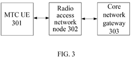
- the present invention further provides an NAS connection establishment system, comprising at least machine type communication (MTC) user equipment (UE) 301, radio access network node 302 and core network node 303, herein:
- MTC machine type communication
- UE user equipment
- core network node 303 herein:
- the radio access network node After the radio access network node receives an AS message, it converts a request reason in the AS message into priority indication information, and includes the information in a signaling to send together with the NAS request message to the core network node, thus the core network node does not need to read the NAS request message to determine the priority of the NAS request message.
- the core network node When a congestion occurs in the core network, the core network node does not need to read the NAS request message to respond the NAS request message, so as to quickly control the network congestion. Therefore, the present invention has very strong industrial applicability.
Abstract
Description
- The present invention relates to the machine type communications technology, and more particularly, to an NAS connection establishment method, system and a radio access network node.
- Machine-to-machine (M2M) refers to all technologies and means for establishing connections between machines. The concept of M2M appeared in the nineties of 20th century, and only stayed in the theoretical stage then. After 2000, with the development of mobile communication technology, the mobile communication technology can be adopted to achieve networking of the machines. In 2002, the M2M service appeared in the market, and has been rapidly developed in the following years, and has become a focus of a large amount of telecommunications equipment manufacturers and telecom operators. Currently, in the worldwide, the number of machines is much more than the number of people, therefore, the M2M technology has good market prospects. Meanwhile, the M2M service has proposed many new requirements on the system, and in order to enhance the competitiveness of the mobile networks in this regard, it needs to optimize the existing mobile networks so as to more effectively support the M2M communication.
- The existing mobile communications network is primarily designed for interpersonal communication, and is not optimized enough for the machine-to-machine communication and the man-to-machine communication. If an operator wants to provide the M2M communication service at low cost, it should reuse existing networks to the most extent, and reduce the impact of the M2M communication on networks as well as and the complexity of operation and maintenance.
- In order to effectively use the existing mobile network resources, the 3rd Generation Partnership Project (3GPP) proposes services based on machine type communication (MTC), including M2M and machine-to-man communications, its service scope is far beyond the conventional human to human (H2H) communication. The MTC is very different from the existing H2H communication mode in terms of access control, billing, security, quality of service (QoS), and service mode.
- The existing 3GPP system architecture comprises: radio access network and core network.
- Herein the radio access network may be a Universal Terrestrial Radio Access Network (UTRAN), an Evolved UTRAN (E-UTRAN) or a GSM EDGE Radio Access Network (GERAN).
- The core network comprises: Mobility Management Entity (MME), Serving Gateway (S-GW), PDN gateway (P-GW) and other network elements. The General Packet Radio Service (GPRS) core network comprises: Serving GPRS Support Node (SGSN) and other network elements.
- The Non Access Stratum (NAS) refers to the control plane high stratum between the User Equipment (UE) and the MME/SGSN, and is located above the Access Stratum (AS). The NAS is mainly responsible for related functions and processes that are not related to the access technologies and are independent of the radio access.
- When initiating an NAS connection request, the MTC UE comprises a low priority indication in the NAS request message, the MTC UE first establishes a radio bearer connection with the radio access network, then the UE sends an AS message carrying the NAS request message to the radio access network, and the radio access network forwards the NAS request message to the core network. Because in general the MTC UE is not sensitive to delay, it is considered to be a UE with a low priority. When a network congestion occurs, the network side can reject low-priority requests.
- For example, when the radio access network is a UTRAN, the radio access network nodes of the UTRAN comprise Radio Network Controller (RNC) and Node B (NB), the UE sends the AS message carrying the NAS request message to the node B, and the node B forwards the AS message to the RNC, and then the RNC forwards the NAS request message to the SGSN over the Iu interface.
- When the radio access network is the E-UTRAN, a radio access network node of the E-UTRAN comprises an evolved Node B (eNB). The UE sends an AS message carrying an NAS request message to the eNB, and the eNB carries the NAS request message in a signaling and sends it to the MME over the S1-MME interface.
- In the abovementioned NAS connection establishment method, the radio access network carries the NAS request message in the signaling and sends it to the SGSN/MME, the SGSN/MME needs to read the signaling to obtain the NAS message, and then learns the priority of the NAS request message by reading the content of the NAS message. If a network congestion occurs, the SGSN/MME cannot quickly judge the priority of the NAS request and thus cannot quickly perform an effective control on the network congestion.
- The object of the embodiment of the present invention is to provide an NAS connection establishment system and method and a radio access network node to quickly control a network congestion.
- To solve the abovementioned technical problem, the following technical solution is used:
- An NAS connection establishment method, comprises:
- a radio access network node receiving an Access Stratum (AS) message carrying a non-access stratum (NAS) request message from a machine type communication (MTC) user equipment (UE), wherein, the AS message further carries a request reason of the AS request message;
- the radio access network node converting the request reason in the AS message into priority indication information, and sending a signaling to a core network node, wherein the signaling comprises the priority indication information and the NAS request message;
- the core network node determining a priority of the NAS request message based on the priority indication information in the signaling;
- when a congestion occurs in the core network, the core network node sends a rejection response message to a UE that sends an NAS request message with a low priority.
- Alternatively, the radio access network node is a radio network controller (RNC) and a Node B, and the core network node is a serving general packet radio service (GPRS) support node (SGSN); or
the radio access network node is an evolved Node B, and the core network node is a mobility management entity (MME). - Alternatively, the signaling is a radio access network application protocol (RANAP) signaling sent over an Iu interface or an S1 Application Protocol (S1AP) signaling sent over an S1-MME interface.
- Alternatively, the AS message is a radio resource control (RRC) message.
- Alternatively, the priority indication information is saved in a newly-added control field or an originally-reserved control field in the signaling.
- Alternatively, the priority indication information is represented with 1 bit or 2 bits.
- A radio access network node, comprising a receiving module, a converting module and a sending module, wherein:
- the receiving module is configured to: receive an access stratum (AS) message carrying a non-access stratum (NAS) request message from a machine type communication (MTC) user equipment (UE), wherein the AS message further carries a request reason of the AS request message;
- the converting module is configured to: convert the request reasons in the AS message into priority indication information;
- the sending module is configured to: send a signaling to a core network node, wherein the signaling comprises the priority indication information and the NAS request message.
- An NAS connection establishment system comprises a machine type communication (MTC) user equipment (UE), a radio access network node and a core network node, wherein:
- the machine type communication (MTC) user equipment (UE) is configured to: send an access stratum (AS) message carrying a non-access stratum (NAS) request message to a radio access network node; wherein the AS message further carries a request reason of the AS request message;
- the radio access network node is configured to: receive the AS message from the MTC UE; convert the request reason in the AS message into priority indication information, and send a signaling to the core network node, wherein the signaling comprises the priority indication information and the NAS request message;
- the core network node is configured to: determine a priority of the NAS request message based on the priority indication information in the signaling; and when a congestion in the core network is detected, send a rejection response message to a UE that sends an NAS request message with a low priority.
- In the NAS connection establishment method, system and a radio access network node in the abovementioned technical solution, after the radio access network node receives an AS message, it converts a request reason in the AS message into priority indication information, and includes the information in a signaling to send together with the NAS request message to the core network node, thus the core network node does not need to read the NAS request message to determine the priority of the NAS request message.
- When a congestion occurs in the core network, the core network node does not need to read the NAS request message to respond the NAS request message, so as to quickly control the network congestion.
- Hereinafter, the accompanying drawings in the embodiments of the present invention will be described, the accompanying drawings in the embodiments are used to further understand the present invention, and serve to explain the present invention together with the specification, and are not used for limiting the protection scope of the present invention.
-
FIG. 1 is a flow chart of an NAS connection establishment method in accordance with an embodiment of the present invention; -
FIG.2 is a schematic diagram of the composition structure of a radio access network node in accordance with an embodiment of the present invention; -
FIG. 3 is a schematic diagram of the composition structure of an NAS connection establishment system in accordance with an embodiment of the present invention. - In order to facilitate the understanding of those skilled in the art, in the following, the present invention will be further described in conjunction with the accompanying drawings, and the accompanying drawings can not be used to limit the protection scope of the present invention.
- Refer to
FIG. 1 , the embodiment of the present invention provides a priority indication method, the method comprises: - in
step 100, the radio access network node receives an AS message carrying an NAS request message from a communications machine type (MTC) user equipment (UE), the AS message carries a request reason of the AS request message. - In the present step, when the UE sends an NAS connection request to the core network, it needs the radio access network node to forward the message, while the radio access network node can only receive the AS message, therefore, the AS message sent by the UE to the radio access network node carries the NAS request message sent to the core network, and also comprises the request reason of the AS request message. The request reason of the AS request message may be Mobile Originated (MO) signaling, MO data, Mobile Terminating (MT) access, emergency call, or delay tolerant access, and so on, herein the delay tolerant access represents that the UE sending the AS request message is a UE with a low priority, such as MTC UE; the NAS request message sent by the UE with a low priority also has a low priority, a low priority indication bit of the low-priority NAS request message is located in the NAS request message, the NAS request message is transparent to the access network node, namely, the access network node would not read contents of the NAS request message, therefore the access network node does not know the contents of the NAS request message.
- In this step, the NAS request message may be an attachment message, a service request message, a Track Area Update (TAU)/Route Area Update (RAU) request message, which is not limited in the present invention.
- In this step, the UE sends the AS message to the radio access network node via an air interface.
- In this step, the AS message is a radio resource control (RRC) message.
- In this step, for the UTRAN, the radio access network node is the RNC and the NB; for the E-UTRAN, the radio access network node is an eNB.
- In
step 101, the radio access network node converts the request reason in the AS message into priority indication information, and sends a signaling to the core network node, the signaling comprises the priority indication information and the NAS request message carried in the AS message. - In this step, when the radio access network node is the RNC and the NB, the RNC sends a Radio Access Network Application Protocol (RANAP) signaling to the SGSN over the Iu interface; when the radio access network node is the eNB, the eNB sends an S1 application protocol (S1AP) signaling to the MME over the S1-MME interface.
- In this step, when the request reason is delay tolerance, it represents that the UE sending the AS message is a UE with a low priority, so that it can be judged that the NAS request message carried in the AS message has a low priority. After receiving the AS message, the radio access network node converts the request reason of delay tolerance to low-priority indication information and sends the information to the core network node.
- In this step, the signaling comprising the priority indication information and the NAS request message carried in the AS message specifically refers to: respectively saving the priority indication information and the NAS request message carried in the AS message into separate control fields of the signaling, herein, the control field where the priority indication information is located may be a newly-added control field or an originally-reserved control field, when there is no control field containing the priority indication information, it defaults to a non-low priority. In this step, one bit can be used to represent the priority indication information, when the bit is 0, it represents a non-low priority, when the bit is 1, it represents a low priority; or 2 bits also be used to represent the priority indication information, for example, when the bits are 00, it represents a low priority, when the bits are 11, it represents a high priority, and 01 or 10 represents a normal priority, and so on.
- In
step 102, the core network node determines the priority of the NAS request message based on the priority indication information in the signaling. Instep 103, it is to judge whether there is a congestion in the core network, and if yes, the process proceeds to step 104, otherwise, it proceeds to step 105. - The core network node judges whether there is a congestion in the core network based on the local indication information, and if there is a congestion, the NAS request message with a low priority is rejected, otherwise the contents of the NAS message are read. The specific judgment method belongs to the related art and will not be repeated here.
- In
step 104, when there is a congestion in the core network, the core network node sends a rejection response message to the UE that sends the NAS request message with a low priority. - In this step, the rejection response message may comprise a backward time, which represents that the core network only processes the NAS request message after the backward time.
- In
step 105, the core network node reads the contents of the NAS message. - In the NAS connection establishment method provided in the present invention, after the radio access network node receives the AS message, it converts the request reason in the AS message into priority indication information, and includes the information in the signaling to send together with the NAS request message to the core network node, thus the core network node does not need to read the NAS request message to determine the priority of the NAS request message. When a congestion occurs in the core network, the core network node does not need to read the NAS request message to respond to the NAS request message, so as to quickly control the network congestion.
- Refer to
FIG. 2 , the embodiment of the present invention further provides a radio access network node, comprising at least receivingmodule 201, convertingmodule 202 and sendingmodule 203, herein: - the receiving
module 201 is configured to: receive an access stratum (AS) message carrying a non-access stratum (NAS) request message from a machine type communication (MTC) user equipment (UE), the AS message further carries a request reason; - the converting
module 202 is configured to: convert the request reason in the AS message into priority indication information; - the sending
module 203 is configured to: send a signaling to a core network node, the signaling comprises the priority indication information and the NAS request message carried in the AS message. - Refer to
FIG. 3 , the present invention further provides an NAS connection establishment system, comprising at least machine type communication (MTC) user equipment (UE) 301, radioaccess network node 302 andcore network node 303, herein: - the machine type communication (MTC) user equipment (UE) 301 is configured to:
- send an access stratum (AS) message carrying a non-access stratum (NAS) request message to a radio access network node; the AS message carries the request reason in the AS request message;
- the radio
access network node 302 is configured to: receive the AS message from the UE; convert the request reason in the AS message into priority indication information, and send a signaling to the core network node, the signaling comprises the priority indication information and the NAS request message carried in the AS message; - the
core network node 303 is configured to: determine the priority of the NAS request message based on the priority indication information in the signaling; and when a congestion in the core network is detected, send a rejection response message to the UE that sends an NAS request message with a low priority. - It should be noted that the embodiments described above are merely easy for those skilled in the art to understand, and are not intended to limit the protection scope of the present invention, and under the premise of without departing from the inventive concept of the present invention, any apparent replacements and improvements made on the present invention by those skilled in the art should be within the protection scope of the present invention.
- In the NAS connection establishment method, system and the radio access network node in the abovementioned technical solution, after the radio access network node receives an AS message, it converts a request reason in the AS message into priority indication information, and includes the information in a signaling to send together with the NAS request message to the core network node, thus the core network node does not need to read the NAS request message to determine the priority of the NAS request message. When a congestion occurs in the core network, the core network node does not need to read the NAS request message to respond the NAS request message, so as to quickly control the network congestion. Therefore, the present invention has very strong industrial applicability.
Claims (8)
- A non-access stratum (NAS) connection establishment method, comprising:a radio access network node receiving an Access Stratum (AS) message carrying a non-access stratum (NAS) request message from a machine type communication (MTC) user equipment (UE), wherein, the AS message further carries a request reason of the AS request message;the radio access network node converting the request reason in the AS message into priority indication information, and sending a signaling to a core network node, wherein the signaling comprises the priority indication information and the NAS request message;the core network node determining a priority of the NAS request message based on the priority indication information in the signaling;when a congestion occurs in the core network, the core network node sends a rejection response message to a UE that sends an NAS request message with a low priority.
- The method of claim 1, wherein,
the radio access network node is a radio network controller (RNC) and a Node B, and the core network node is a serving general packet radio service (GPRS) support node (SGSN); or
the radio access network node is an evolved Node B, and the core network node is a mobility management entity (MME). - The method of claim 2, wherein, the signaling is a radio access network application protocol (RANAP) signaling sent over an Iu interface or an S1 Application Protocol (S1AP) signaling sent over an S1-MME interface.
- The method of claim 1, wherein, the AS message is a radio resource control (RRC) message.
- The method of claim 1, wherein, the priority indication information is saved in a newly-added control field or an originally-reserved control field in the signaling.
- The method of claim 1, wherein, the priority indication information is represented with 1 bit or 2 bits.
- A radio access network node, comprising a receiving module, a converting module and a sending module, wherein:the receiving module is configured to: receive an access stratum (AS) message carrying a non-access stratum (NAS) request message from a machine type communication (MTC) user equipment (UE), wherein the AS message further carries a request reason of the AS request message;the converting module is configured to: convert the request reasons in the AS message into priority indication information;the sending module is configured to: send a signaling to a core network node, wherein the signaling comprises the priority indication information and the NAS request message.
- An NAS connection establishment system, comprising a machine type communication (MTC) user equipment (UE), a radio access network node and a core network node, wherein:the machine type communication (MTC) user equipment (UE) is configured to: send an access stratum (AS) message carrying a non-access stratum (NAS) request message to a radio access network node; wherein the AS message further carries a request reason of the AS request message;the radio access network node is configured to: receive the AS message from the MTC UE; convert the request reason in the AS message into priority indication information, and send a signaling to the core network node, wherein the signaling comprises the priority indication information and the NAS request message;the core network node is configured to: determine a priority of the NAS request message based on the priority indication information in the signaling; and when a congestion in the core network is detected, send a rejection response message to a UE that sends an NAS request message with a low priority.
Applications Claiming Priority (2)
| Application Number | Priority Date | Filing Date | Title |
|---|---|---|---|
| CN201310628625.8A CN104684021B (en) | 2013-11-29 | 2013-11-29 | Method and system for establishing NAS connection and wireless access network node |
| PCT/CN2014/077855 WO2014183685A1 (en) | 2013-11-29 | 2014-05-20 | Nas connection establishment method, system and radio access network node |
Publications (3)
| Publication Number | Publication Date |
|---|---|
| EP3059996A1 true EP3059996A1 (en) | 2016-08-24 |
| EP3059996A4 EP3059996A4 (en) | 2017-08-02 |
| EP3059996B1 EP3059996B1 (en) | 2019-10-16 |
Family
ID=51897744
Family Applications (1)
| Application Number | Title | Priority Date | Filing Date |
|---|---|---|---|
| EP14797147.7A Active EP3059996B1 (en) | 2013-11-29 | 2014-05-20 | Nas connection establishment method, system and radio access network node |
Country Status (4)
| Country | Link |
|---|---|
| US (1) | US9723648B2 (en) |
| EP (1) | EP3059996B1 (en) |
| CN (1) | CN104684021B (en) |
| WO (1) | WO2014183685A1 (en) |
Families Citing this family (4)
| Publication number | Priority date | Publication date | Assignee | Title |
|---|---|---|---|---|
| CN107872859B (en) * | 2016-09-26 | 2021-08-24 | 中兴通讯股份有限公司 | Method and device for called access |
| CN108377527B (en) * | 2016-11-02 | 2021-02-26 | 华为技术有限公司 | Network architecture suitable for flexible deployment scene |
| CN109963344A (en) * | 2017-12-26 | 2019-07-02 | 海能达通信股份有限公司 | The processing method and relevant device of downlink NAS signaling |
| WO2023087328A1 (en) * | 2021-11-22 | 2023-05-25 | Oppo广东移动通信有限公司 | Handover method and apparatus, device, and storage medium |
Family Cites Families (12)
| Publication number | Priority date | Publication date | Assignee | Title |
|---|---|---|---|---|
| CN101651899B (en) * | 2008-08-12 | 2012-12-05 | 中兴通讯股份有限公司 | Method for requesting reestablishment of LTE RRC connection, method for setting cause value and terminal |
| CN102256218A (en) * | 2010-05-21 | 2011-11-23 | 电信科学技术研究院 | Transmission method and device for preferential warning message in machine type communication |
| CN102448142B (en) * | 2010-09-30 | 2015-06-03 | 中兴通讯股份有限公司 | Method and device for controlling terminal to select network |
| CN102448117B (en) * | 2010-09-30 | 2016-04-13 | 电信科学技术研究院 | A kind of method and apparatus of spatial load forecasting |
| CN102469519A (en) * | 2010-11-05 | 2012-05-23 | 大唐移动通信设备有限公司 | Control method of waiting time and equipment thereof |
| CN102469520B (en) * | 2010-11-09 | 2015-09-09 | 大唐移动通信设备有限公司 | A kind of jamming control method and equipment |
| US8787159B2 (en) * | 2011-04-14 | 2014-07-22 | Alcatel Lucent | Mechanism for wireless access networks to throttle traffic during congestion |
| CN102395175B (en) * | 2011-06-30 | 2018-01-23 | 中兴通讯股份有限公司 | A kind of PLMN system of selection and mobile terminal |
| CN102300285B (en) * | 2011-09-29 | 2014-02-12 | 电信科学技术研究院 | Access control method and equipment |
| CN103096376A (en) * | 2011-11-04 | 2013-05-08 | 中兴通讯股份有限公司 | Method and system for network congestion control |
| JP5893760B2 (en) * | 2012-02-06 | 2016-03-23 | インテル コーポレイション | Device used by user device, management device, user device, and management method |
| US9294213B2 (en) * | 2012-05-11 | 2016-03-22 | Intel Corporation | Packet data network connections for multi priority wireless devices |
-
2013
- 2013-11-29 CN CN201310628625.8A patent/CN104684021B/en active Active
-
2014
- 2014-05-20 WO PCT/CN2014/077855 patent/WO2014183685A1/en active Application Filing
- 2014-05-20 EP EP14797147.7A patent/EP3059996B1/en active Active
- 2014-05-20 US US15/039,035 patent/US9723648B2/en active Active
Also Published As
| Publication number | Publication date |
|---|---|
| US20170071025A1 (en) | 2017-03-09 |
| CN104684021B (en) | 2020-01-14 |
| US9723648B2 (en) | 2017-08-01 |
| WO2014183685A1 (en) | 2014-11-20 |
| EP3059996A4 (en) | 2017-08-02 |
| EP3059996B1 (en) | 2019-10-16 |
| CN104684021A (en) | 2015-06-03 |
Similar Documents
| Publication | Publication Date | Title |
|---|---|---|
| US11076376B2 (en) | De-registration method in wireless communication system and apparatus therefor | |
| US11375471B2 (en) | Method for performing service request procedure and apparatus therefor in wireless communication system | |
| US11606734B2 (en) | Handover method in wireless communication system and apparatus therefor | |
| EP3432641A1 (en) | Method for interworking between networks in wireless communication system and apparatus therefor | |
| US10959142B2 (en) | Extended buffering management | |
| US8660078B2 (en) | Data radio bearer (DRB) enhancements for small data transmissions apparatus, systems, and methods | |
| EP3619985A1 (en) | Paging policy differentiation in 5g system | |
| US8743752B2 (en) | Method and apparatus for status transition | |
| US9723648B2 (en) | NAS connection establishment method, system and radio access network node |
Legal Events
| Date | Code | Title | Description |
|---|---|---|---|
| PUAI | Public reference made under article 153(3) epc to a published international application that has entered the european phase |
Free format text: ORIGINAL CODE: 0009012 |
|
| 17P | Request for examination filed |
Effective date: 20160519 |
|
| AK | Designated contracting states |
Kind code of ref document: A1 Designated state(s): AL AT BE BG CH CY CZ DE DK EE ES FI FR GB GR HR HU IE IS IT LI LT LU LV MC MK MT NL NO PL PT RO RS SE SI SK SM TR |
|
| AX | Request for extension of the european patent |
Extension state: BA ME |
|
| DAX | Request for extension of the european patent (deleted) | ||
| RIC1 | Information provided on ipc code assigned before grant |
Ipc: H04W 48/06 20090101ALI20170601BHEP Ipc: H04W 76/02 20090101ALI20170601BHEP Ipc: H04W 28/12 20090101ALI20170601BHEP Ipc: H04W 28/02 20090101AFI20170601BHEP Ipc: H04W 28/16 20090101ALI20170601BHEP |
|
| RIC1 | Information provided on ipc code assigned before grant |
Ipc: H04W 76/02 20090101ALI20170622BHEP Ipc: H04W 28/16 20090101ALI20170622BHEP Ipc: H04W 28/02 20090101AFI20170622BHEP Ipc: H04W 48/06 20090101ALI20170622BHEP Ipc: H04W 28/12 20090101ALI20170622BHEP |
|
| A4 | Supplementary search report drawn up and despatched |
Effective date: 20170630 |
|
| GRAP | Despatch of communication of intention to grant a patent |
Free format text: ORIGINAL CODE: EPIDOSNIGR1 |
|
| STAA | Information on the status of an ep patent application or granted ep patent |
Free format text: STATUS: GRANT OF PATENT IS INTENDED |
|
| RIC1 | Information provided on ipc code assigned before grant |
Ipc: H04W 28/12 20090101ALI20190411BHEP Ipc: H04W 88/12 20090101ALI20190411BHEP Ipc: H04W 48/06 20090101ALI20190411BHEP Ipc: H04W 28/02 20090101AFI20190411BHEP Ipc: H04W 76/18 20180101ALI20190411BHEP Ipc: H04W 28/16 20090101ALI20190411BHEP Ipc: H04W 76/27 20180101ALI20190411BHEP |
|
| INTG | Intention to grant announced |
Effective date: 20190507 |
|
| GRAS | Grant fee paid |
Free format text: ORIGINAL CODE: EPIDOSNIGR3 |
|
| GRAA | (expected) grant |
Free format text: ORIGINAL CODE: 0009210 |
|
| STAA | Information on the status of an ep patent application or granted ep patent |
Free format text: STATUS: THE PATENT HAS BEEN GRANTED |
|
| AK | Designated contracting states |
Kind code of ref document: B1 Designated state(s): AL AT BE BG CH CY CZ DE DK EE ES FI FR GB GR HR HU IE IS IT LI LT LU LV MC MK MT NL NO PL PT RO RS SE SI SK SM TR |
|
| REG | Reference to a national code |
Ref country code: GB Ref legal event code: FG4D |
|
| REG | Reference to a national code |
Ref country code: CH Ref legal event code: EP |
|
| REG | Reference to a national code |
Ref country code: DE Ref legal event code: R096 Ref document number: 602014055314 Country of ref document: DE |
|
| REG | Reference to a national code |
Ref country code: IE Ref legal event code: FG4D |
|
| REG | Reference to a national code |
Ref country code: AT Ref legal event code: REF Ref document number: 1192540 Country of ref document: AT Kind code of ref document: T Effective date: 20191115 |
|
| REG | Reference to a national code |
Ref country code: NL Ref legal event code: MP Effective date: 20191016 |
|
| REG | Reference to a national code |
Ref country code: LT Ref legal event code: MG4D |
|
| REG | Reference to a national code |
Ref country code: AT Ref legal event code: MK05 Ref document number: 1192540 Country of ref document: AT Kind code of ref document: T Effective date: 20191016 |
|
| PG25 | Lapsed in a contracting state [announced via postgrant information from national office to epo] |
Ref country code: PL Free format text: LAPSE BECAUSE OF FAILURE TO SUBMIT A TRANSLATION OF THE DESCRIPTION OR TO PAY THE FEE WITHIN THE PRESCRIBED TIME-LIMIT Effective date: 20191016 Ref country code: LT Free format text: LAPSE BECAUSE OF FAILURE TO SUBMIT A TRANSLATION OF THE DESCRIPTION OR TO PAY THE FEE WITHIN THE PRESCRIBED TIME-LIMIT Effective date: 20191016 Ref country code: AT Free format text: LAPSE BECAUSE OF FAILURE TO SUBMIT A TRANSLATION OF THE DESCRIPTION OR TO PAY THE FEE WITHIN THE PRESCRIBED TIME-LIMIT Effective date: 20191016 Ref country code: SE Free format text: LAPSE BECAUSE OF FAILURE TO SUBMIT A TRANSLATION OF THE DESCRIPTION OR TO PAY THE FEE WITHIN THE PRESCRIBED TIME-LIMIT Effective date: 20191016 Ref country code: NL Free format text: LAPSE BECAUSE OF FAILURE TO SUBMIT A TRANSLATION OF THE DESCRIPTION OR TO PAY THE FEE WITHIN THE PRESCRIBED TIME-LIMIT Effective date: 20191016 Ref country code: LV Free format text: LAPSE BECAUSE OF FAILURE TO SUBMIT A TRANSLATION OF THE DESCRIPTION OR TO PAY THE FEE WITHIN THE PRESCRIBED TIME-LIMIT Effective date: 20191016 Ref country code: FI Free format text: LAPSE BECAUSE OF FAILURE TO SUBMIT A TRANSLATION OF THE DESCRIPTION OR TO PAY THE FEE WITHIN THE PRESCRIBED TIME-LIMIT Effective date: 20191016 Ref country code: PT Free format text: LAPSE BECAUSE OF FAILURE TO SUBMIT A TRANSLATION OF THE DESCRIPTION OR TO PAY THE FEE WITHIN THE PRESCRIBED TIME-LIMIT Effective date: 20200217 Ref country code: BG Free format text: LAPSE BECAUSE OF FAILURE TO SUBMIT A TRANSLATION OF THE DESCRIPTION OR TO PAY THE FEE WITHIN THE PRESCRIBED TIME-LIMIT Effective date: 20200116 Ref country code: NO Free format text: LAPSE BECAUSE OF FAILURE TO SUBMIT A TRANSLATION OF THE DESCRIPTION OR TO PAY THE FEE WITHIN THE PRESCRIBED TIME-LIMIT Effective date: 20200116 Ref country code: GR Free format text: LAPSE BECAUSE OF FAILURE TO SUBMIT A TRANSLATION OF THE DESCRIPTION OR TO PAY THE FEE WITHIN THE PRESCRIBED TIME-LIMIT Effective date: 20200117 |
|
| PG25 | Lapsed in a contracting state [announced via postgrant information from national office to epo] |
Ref country code: RS Free format text: LAPSE BECAUSE OF FAILURE TO SUBMIT A TRANSLATION OF THE DESCRIPTION OR TO PAY THE FEE WITHIN THE PRESCRIBED TIME-LIMIT Effective date: 20191016 Ref country code: HR Free format text: LAPSE BECAUSE OF FAILURE TO SUBMIT A TRANSLATION OF THE DESCRIPTION OR TO PAY THE FEE WITHIN THE PRESCRIBED TIME-LIMIT Effective date: 20191016 Ref country code: IS Free format text: LAPSE BECAUSE OF FAILURE TO SUBMIT A TRANSLATION OF THE DESCRIPTION OR TO PAY THE FEE WITHIN THE PRESCRIBED TIME-LIMIT Effective date: 20200224 |
|
| PG25 | Lapsed in a contracting state [announced via postgrant information from national office to epo] |
Ref country code: AL Free format text: LAPSE BECAUSE OF FAILURE TO SUBMIT A TRANSLATION OF THE DESCRIPTION OR TO PAY THE FEE WITHIN THE PRESCRIBED TIME-LIMIT Effective date: 20191016 |
|
| REG | Reference to a national code |
Ref country code: DE Ref legal event code: R097 Ref document number: 602014055314 Country of ref document: DE |
|
| PG2D | Information on lapse in contracting state deleted |
Ref country code: IS |
|
| PG25 | Lapsed in a contracting state [announced via postgrant information from national office to epo] |
Ref country code: RO Free format text: LAPSE BECAUSE OF FAILURE TO SUBMIT A TRANSLATION OF THE DESCRIPTION OR TO PAY THE FEE WITHIN THE PRESCRIBED TIME-LIMIT Effective date: 20191016 Ref country code: CZ Free format text: LAPSE BECAUSE OF FAILURE TO SUBMIT A TRANSLATION OF THE DESCRIPTION OR TO PAY THE FEE WITHIN THE PRESCRIBED TIME-LIMIT Effective date: 20191016 Ref country code: ES Free format text: LAPSE BECAUSE OF FAILURE TO SUBMIT A TRANSLATION OF THE DESCRIPTION OR TO PAY THE FEE WITHIN THE PRESCRIBED TIME-LIMIT Effective date: 20191016 Ref country code: EE Free format text: LAPSE BECAUSE OF FAILURE TO SUBMIT A TRANSLATION OF THE DESCRIPTION OR TO PAY THE FEE WITHIN THE PRESCRIBED TIME-LIMIT Effective date: 20191016 Ref country code: DK Free format text: LAPSE BECAUSE OF FAILURE TO SUBMIT A TRANSLATION OF THE DESCRIPTION OR TO PAY THE FEE WITHIN THE PRESCRIBED TIME-LIMIT Effective date: 20191016 Ref country code: IS Free format text: LAPSE BECAUSE OF FAILURE TO SUBMIT A TRANSLATION OF THE DESCRIPTION OR TO PAY THE FEE WITHIN THE PRESCRIBED TIME-LIMIT Effective date: 20200216 |
|
| PLBE | No opposition filed within time limit |
Free format text: ORIGINAL CODE: 0009261 |
|
| STAA | Information on the status of an ep patent application or granted ep patent |
Free format text: STATUS: NO OPPOSITION FILED WITHIN TIME LIMIT |
|
| PG25 | Lapsed in a contracting state [announced via postgrant information from national office to epo] |
Ref country code: IT Free format text: LAPSE BECAUSE OF FAILURE TO SUBMIT A TRANSLATION OF THE DESCRIPTION OR TO PAY THE FEE WITHIN THE PRESCRIBED TIME-LIMIT Effective date: 20191016 Ref country code: SM Free format text: LAPSE BECAUSE OF FAILURE TO SUBMIT A TRANSLATION OF THE DESCRIPTION OR TO PAY THE FEE WITHIN THE PRESCRIBED TIME-LIMIT Effective date: 20191016 Ref country code: SK Free format text: LAPSE BECAUSE OF FAILURE TO SUBMIT A TRANSLATION OF THE DESCRIPTION OR TO PAY THE FEE WITHIN THE PRESCRIBED TIME-LIMIT Effective date: 20191016 |
|
| 26N | No opposition filed |
Effective date: 20200717 |
|
| PG25 | Lapsed in a contracting state [announced via postgrant information from national office to epo] |
Ref country code: SI Free format text: LAPSE BECAUSE OF FAILURE TO SUBMIT A TRANSLATION OF THE DESCRIPTION OR TO PAY THE FEE WITHIN THE PRESCRIBED TIME-LIMIT Effective date: 20191016 |
|
| PG25 | Lapsed in a contracting state [announced via postgrant information from national office to epo] |
Ref country code: LI Free format text: LAPSE BECAUSE OF NON-PAYMENT OF DUE FEES Effective date: 20200531 Ref country code: CH Free format text: LAPSE BECAUSE OF NON-PAYMENT OF DUE FEES Effective date: 20200531 Ref country code: MC Free format text: LAPSE BECAUSE OF FAILURE TO SUBMIT A TRANSLATION OF THE DESCRIPTION OR TO PAY THE FEE WITHIN THE PRESCRIBED TIME-LIMIT Effective date: 20191016 |
|
| REG | Reference to a national code |
Ref country code: BE Ref legal event code: MM Effective date: 20200531 |
|
| PG25 | Lapsed in a contracting state [announced via postgrant information from national office to epo] |
Ref country code: LU Free format text: LAPSE BECAUSE OF NON-PAYMENT OF DUE FEES Effective date: 20200520 |
|
| PG25 | Lapsed in a contracting state [announced via postgrant information from national office to epo] |
Ref country code: IE Free format text: LAPSE BECAUSE OF NON-PAYMENT OF DUE FEES Effective date: 20200520 |
|
| PG25 | Lapsed in a contracting state [announced via postgrant information from national office to epo] |
Ref country code: BE Free format text: LAPSE BECAUSE OF NON-PAYMENT OF DUE FEES Effective date: 20200531 |
|
| PG25 | Lapsed in a contracting state [announced via postgrant information from national office to epo] |
Ref country code: TR Free format text: LAPSE BECAUSE OF FAILURE TO SUBMIT A TRANSLATION OF THE DESCRIPTION OR TO PAY THE FEE WITHIN THE PRESCRIBED TIME-LIMIT Effective date: 20191016 Ref country code: MT Free format text: LAPSE BECAUSE OF FAILURE TO SUBMIT A TRANSLATION OF THE DESCRIPTION OR TO PAY THE FEE WITHIN THE PRESCRIBED TIME-LIMIT Effective date: 20191016 Ref country code: CY Free format text: LAPSE BECAUSE OF FAILURE TO SUBMIT A TRANSLATION OF THE DESCRIPTION OR TO PAY THE FEE WITHIN THE PRESCRIBED TIME-LIMIT Effective date: 20191016 |
|
| PG25 | Lapsed in a contracting state [announced via postgrant information from national office to epo] |
Ref country code: MK Free format text: LAPSE BECAUSE OF FAILURE TO SUBMIT A TRANSLATION OF THE DESCRIPTION OR TO PAY THE FEE WITHIN THE PRESCRIBED TIME-LIMIT Effective date: 20191016 |
|
| REG | Reference to a national code |
Ref country code: FR Ref legal event code: PLFP Year of fee payment: 10 |
|
| PGFP | Annual fee paid to national office [announced via postgrant information from national office to epo] |
Ref country code: GB Payment date: 20230330 Year of fee payment: 10 |
|
| PGFP | Annual fee paid to national office [announced via postgrant information from national office to epo] |
Ref country code: FR Payment date: 20230411 Year of fee payment: 10 Ref country code: DE Payment date: 20230331 Year of fee payment: 10 |