EP3059797A1 - Detection apparatus for detecting locked states of multiple electrodes by using battery sensor - Google Patents
Detection apparatus for detecting locked states of multiple electrodes by using battery sensor Download PDFInfo
- Publication number
- EP3059797A1 EP3059797A1 EP13895480.5A EP13895480A EP3059797A1 EP 3059797 A1 EP3059797 A1 EP 3059797A1 EP 13895480 A EP13895480 A EP 13895480A EP 3059797 A1 EP3059797 A1 EP 3059797A1
- Authority
- EP
- European Patent Office
- Prior art keywords
- electrode
- positioning
- contact
- locking
- bolt
- Prior art date
- Legal status (The legal status is an assumption and is not a legal conclusion. Google has not performed a legal analysis and makes no representation as to the accuracy of the status listed.)
- Granted
Links
Images


Classifications
-
- H—ELECTRICITY
- H01—ELECTRIC ELEMENTS
- H01M—PROCESSES OR MEANS, e.g. BATTERIES, FOR THE DIRECT CONVERSION OF CHEMICAL ENERGY INTO ELECTRICAL ENERGY
- H01M50/00—Constructional details or processes of manufacture of the non-active parts of electrochemical cells other than fuel cells, e.g. hybrid cells
- H01M50/50—Current conducting connections for cells or batteries
- H01M50/543—Terminals
- H01M50/552—Terminals characterised by their shape
- H01M50/561—Hollow metallic terminals, e.g. terminal bushings
-
- G—PHYSICS
- G01—MEASURING; TESTING
- G01R—MEASURING ELECTRIC VARIABLES; MEASURING MAGNETIC VARIABLES
- G01R31/00—Arrangements for testing electric properties; Arrangements for locating electric faults; Arrangements for electrical testing characterised by what is being tested not provided for elsewhere
- G01R31/50—Testing of electric apparatus, lines, cables or components for short-circuits, continuity, leakage current or incorrect line connections
- G01R31/66—Testing of connections, e.g. of plugs or non-disconnectable joints
- G01R31/68—Testing of releasable connections, e.g. of terminals mounted on a printed circuit board
-
- B—PERFORMING OPERATIONS; TRANSPORTING
- B60—VEHICLES IN GENERAL
- B60L—PROPULSION OF ELECTRICALLY-PROPELLED VEHICLES; SUPPLYING ELECTRIC POWER FOR AUXILIARY EQUIPMENT OF ELECTRICALLY-PROPELLED VEHICLES; ELECTRODYNAMIC BRAKE SYSTEMS FOR VEHICLES IN GENERAL; MAGNETIC SUSPENSION OR LEVITATION FOR VEHICLES; MONITORING OPERATING VARIABLES OF ELECTRICALLY-PROPELLED VEHICLES; ELECTRIC SAFETY DEVICES FOR ELECTRICALLY-PROPELLED VEHICLES
- B60L58/00—Methods or circuit arrangements for monitoring or controlling batteries or fuel cells, specially adapted for electric vehicles
- B60L58/10—Methods or circuit arrangements for monitoring or controlling batteries or fuel cells, specially adapted for electric vehicles for monitoring or controlling batteries
-
- G—PHYSICS
- G01—MEASURING; TESTING
- G01L—MEASURING FORCE, STRESS, TORQUE, WORK, MECHANICAL POWER, MECHANICAL EFFICIENCY, OR FLUID PRESSURE
- G01L5/00—Apparatus for, or methods of, measuring force, work, mechanical power, or torque, specially adapted for specific purposes
- G01L5/24—Apparatus for, or methods of, measuring force, work, mechanical power, or torque, specially adapted for specific purposes for determining value of torque or twisting moment for tightening a nut or other member which is similarly stressed
- G01L5/243—Apparatus for, or methods of, measuring force, work, mechanical power, or torque, specially adapted for specific purposes for determining value of torque or twisting moment for tightening a nut or other member which is similarly stressed using washers
-
- G—PHYSICS
- G01—MEASURING; TESTING
- G01R—MEASURING ELECTRIC VARIABLES; MEASURING MAGNETIC VARIABLES
- G01R31/00—Arrangements for testing electric properties; Arrangements for locating electric faults; Arrangements for electrical testing characterised by what is being tested not provided for elsewhere
- G01R31/005—Testing of electric installations on transport means
- G01R31/006—Testing of electric installations on transport means on road vehicles, e.g. automobiles or trucks
-
- G—PHYSICS
- G01—MEASURING; TESTING
- G01R—MEASURING ELECTRIC VARIABLES; MEASURING MAGNETIC VARIABLES
- G01R31/00—Arrangements for testing electric properties; Arrangements for locating electric faults; Arrangements for electrical testing characterised by what is being tested not provided for elsewhere
- G01R31/50—Testing of electric apparatus, lines, cables or components for short-circuits, continuity, leakage current or incorrect line connections
- G01R31/66—Testing of connections, e.g. of plugs or non-disconnectable joints
- G01R31/68—Testing of releasable connections, e.g. of terminals mounted on a printed circuit board
- G01R31/69—Testing of releasable connections, e.g. of terminals mounted on a printed circuit board of terminals at the end of a cable or a wire harness; of plugs; of sockets, e.g. wall sockets or power sockets in appliances
-
- H—ELECTRICITY
- H01—ELECTRIC ELEMENTS
- H01M—PROCESSES OR MEANS, e.g. BATTERIES, FOR THE DIRECT CONVERSION OF CHEMICAL ENERGY INTO ELECTRICAL ENERGY
- H01M10/00—Secondary cells; Manufacture thereof
- H01M10/42—Methods or arrangements for servicing or maintenance of secondary cells or secondary half-cells
- H01M10/4207—Methods or arrangements for servicing or maintenance of secondary cells or secondary half-cells for several batteries or cells simultaneously or sequentially
-
- H—ELECTRICITY
- H01—ELECTRIC ELEMENTS
- H01M—PROCESSES OR MEANS, e.g. BATTERIES, FOR THE DIRECT CONVERSION OF CHEMICAL ENERGY INTO ELECTRICAL ENERGY
- H01M10/00—Secondary cells; Manufacture thereof
- H01M10/42—Methods or arrangements for servicing or maintenance of secondary cells or secondary half-cells
- H01M10/425—Structural combination with electronic components, e.g. electronic circuits integrated to the outside of the casing
-
- H—ELECTRICITY
- H01—ELECTRIC ELEMENTS
- H01M—PROCESSES OR MEANS, e.g. BATTERIES, FOR THE DIRECT CONVERSION OF CHEMICAL ENERGY INTO ELECTRICAL ENERGY
- H01M10/00—Secondary cells; Manufacture thereof
- H01M10/42—Methods or arrangements for servicing or maintenance of secondary cells or secondary half-cells
- H01M10/48—Accumulators combined with arrangements for measuring, testing or indicating the condition of cells, e.g. the level or density of the electrolyte
- H01M10/482—Accumulators combined with arrangements for measuring, testing or indicating the condition of cells, e.g. the level or density of the electrolyte for several batteries or cells simultaneously or sequentially
-
- H—ELECTRICITY
- H01—ELECTRIC ELEMENTS
- H01M—PROCESSES OR MEANS, e.g. BATTERIES, FOR THE DIRECT CONVERSION OF CHEMICAL ENERGY INTO ELECTRICAL ENERGY
- H01M10/00—Secondary cells; Manufacture thereof
- H01M10/42—Methods or arrangements for servicing or maintenance of secondary cells or secondary half-cells
- H01M10/48—Accumulators combined with arrangements for measuring, testing or indicating the condition of cells, e.g. the level or density of the electrolyte
- H01M10/488—Cells or batteries combined with indicating means for external visualization of the condition, e.g. by change of colour or of light density
-
- H—ELECTRICITY
- H01—ELECTRIC ELEMENTS
- H01M—PROCESSES OR MEANS, e.g. BATTERIES, FOR THE DIRECT CONVERSION OF CHEMICAL ENERGY INTO ELECTRICAL ENERGY
- H01M50/00—Constructional details or processes of manufacture of the non-active parts of electrochemical cells other than fuel cells, e.g. hybrid cells
- H01M50/20—Mountings; Secondary casings or frames; Racks, modules or packs; Suspension devices; Shock absorbers; Transport or carrying devices; Holders
- H01M50/204—Racks, modules or packs for multiple batteries or multiple cells
- H01M50/207—Racks, modules or packs for multiple batteries or multiple cells characterised by their shape
- H01M50/209—Racks, modules or packs for multiple batteries or multiple cells characterised by their shape adapted for prismatic or rectangular cells
-
- H—ELECTRICITY
- H01—ELECTRIC ELEMENTS
- H01M—PROCESSES OR MEANS, e.g. BATTERIES, FOR THE DIRECT CONVERSION OF CHEMICAL ENERGY INTO ELECTRICAL ENERGY
- H01M50/00—Constructional details or processes of manufacture of the non-active parts of electrochemical cells other than fuel cells, e.g. hybrid cells
- H01M50/20—Mountings; Secondary casings or frames; Racks, modules or packs; Suspension devices; Shock absorbers; Transport or carrying devices; Holders
- H01M50/249—Mountings; Secondary casings or frames; Racks, modules or packs; Suspension devices; Shock absorbers; Transport or carrying devices; Holders specially adapted for aircraft or vehicles, e.g. cars or trains
-
- H—ELECTRICITY
- H01—ELECTRIC ELEMENTS
- H01M—PROCESSES OR MEANS, e.g. BATTERIES, FOR THE DIRECT CONVERSION OF CHEMICAL ENERGY INTO ELECTRICAL ENERGY
- H01M50/00—Constructional details or processes of manufacture of the non-active parts of electrochemical cells other than fuel cells, e.g. hybrid cells
- H01M50/50—Current conducting connections for cells or batteries
- H01M50/502—Interconnectors for connecting terminals of adjacent batteries; Interconnectors for connecting cells outside a battery casing
- H01M50/509—Interconnectors for connecting terminals of adjacent batteries; Interconnectors for connecting cells outside a battery casing characterised by the type of connection, e.g. mixed connections
- H01M50/512—Connection only in parallel
-
- H—ELECTRICITY
- H01—ELECTRIC ELEMENTS
- H01M—PROCESSES OR MEANS, e.g. BATTERIES, FOR THE DIRECT CONVERSION OF CHEMICAL ENERGY INTO ELECTRICAL ENERGY
- H01M50/00—Constructional details or processes of manufacture of the non-active parts of electrochemical cells other than fuel cells, e.g. hybrid cells
- H01M50/50—Current conducting connections for cells or batteries
- H01M50/502—Interconnectors for connecting terminals of adjacent batteries; Interconnectors for connecting cells outside a battery casing
- H01M50/514—Methods for interconnecting adjacent batteries or cells
- H01M50/517—Methods for interconnecting adjacent batteries or cells by fixing means, e.g. screws, rivets or bolts
-
- H—ELECTRICITY
- H01—ELECTRIC ELEMENTS
- H01M—PROCESSES OR MEANS, e.g. BATTERIES, FOR THE DIRECT CONVERSION OF CHEMICAL ENERGY INTO ELECTRICAL ENERGY
- H01M50/00—Constructional details or processes of manufacture of the non-active parts of electrochemical cells other than fuel cells, e.g. hybrid cells
- H01M50/50—Current conducting connections for cells or batteries
- H01M50/543—Terminals
- H01M50/564—Terminals characterised by their manufacturing process
- H01M50/567—Terminals characterised by their manufacturing process by fixing means, e.g. screws, rivets or bolts
-
- H—ELECTRICITY
- H01—ELECTRIC ELEMENTS
- H01M—PROCESSES OR MEANS, e.g. BATTERIES, FOR THE DIRECT CONVERSION OF CHEMICAL ENERGY INTO ELECTRICAL ENERGY
- H01M50/00—Constructional details or processes of manufacture of the non-active parts of electrochemical cells other than fuel cells, e.g. hybrid cells
- H01M50/50—Current conducting connections for cells or batteries
- H01M50/572—Means for preventing undesired use or discharge
- H01M50/574—Devices or arrangements for the interruption of current
- H01M50/579—Devices or arrangements for the interruption of current in response to shock
-
- B—PERFORMING OPERATIONS; TRANSPORTING
- B60—VEHICLES IN GENERAL
- B60Y—INDEXING SCHEME RELATING TO ASPECTS CROSS-CUTTING VEHICLE TECHNOLOGY
- B60Y2200/00—Type of vehicle
- B60Y2200/90—Vehicles comprising electric prime movers
- B60Y2200/91—Electric vehicles
-
- H—ELECTRICITY
- H01—ELECTRIC ELEMENTS
- H01M—PROCESSES OR MEANS, e.g. BATTERIES, FOR THE DIRECT CONVERSION OF CHEMICAL ENERGY INTO ELECTRICAL ENERGY
- H01M2200/00—Safety devices for primary or secondary batteries
- H01M2200/20—Pressure-sensitive devices
-
- H—ELECTRICITY
- H01—ELECTRIC ELEMENTS
- H01M—PROCESSES OR MEANS, e.g. BATTERIES, FOR THE DIRECT CONVERSION OF CHEMICAL ENERGY INTO ELECTRICAL ENERGY
- H01M2220/00—Batteries for particular applications
- H01M2220/20—Batteries in motive systems, e.g. vehicle, ship, plane
-
- H—ELECTRICITY
- H01—ELECTRIC ELEMENTS
- H01M—PROCESSES OR MEANS, e.g. BATTERIES, FOR THE DIRECT CONVERSION OF CHEMICAL ENERGY INTO ELECTRICAL ENERGY
- H01M50/00—Constructional details or processes of manufacture of the non-active parts of electrochemical cells other than fuel cells, e.g. hybrid cells
- H01M50/50—Current conducting connections for cells or batteries
- H01M50/543—Terminals
- H01M50/547—Terminals characterised by the disposition of the terminals on the cells
- H01M50/55—Terminals characterised by the disposition of the terminals on the cells on the same side of the cell
-
- Y—GENERAL TAGGING OF NEW TECHNOLOGICAL DEVELOPMENTS; GENERAL TAGGING OF CROSS-SECTIONAL TECHNOLOGIES SPANNING OVER SEVERAL SECTIONS OF THE IPC; TECHNICAL SUBJECTS COVERED BY FORMER USPC CROSS-REFERENCE ART COLLECTIONS [XRACs] AND DIGESTS
- Y02—TECHNOLOGIES OR APPLICATIONS FOR MITIGATION OR ADAPTATION AGAINST CLIMATE CHANGE
- Y02E—REDUCTION OF GREENHOUSE GAS [GHG] EMISSIONS, RELATED TO ENERGY GENERATION, TRANSMISSION OR DISTRIBUTION
- Y02E60/00—Enabling technologies; Technologies with a potential or indirect contribution to GHG emissions mitigation
- Y02E60/10—Energy storage using batteries
-
- Y—GENERAL TAGGING OF NEW TECHNOLOGICAL DEVELOPMENTS; GENERAL TAGGING OF CROSS-SECTIONAL TECHNOLOGIES SPANNING OVER SEVERAL SECTIONS OF THE IPC; TECHNICAL SUBJECTS COVERED BY FORMER USPC CROSS-REFERENCE ART COLLECTIONS [XRACs] AND DIGESTS
- Y02—TECHNOLOGIES OR APPLICATIONS FOR MITIGATION OR ADAPTATION AGAINST CLIMATE CHANGE
- Y02T—CLIMATE CHANGE MITIGATION TECHNOLOGIES RELATED TO TRANSPORTATION
- Y02T10/00—Road transport of goods or passengers
- Y02T10/60—Other road transportation technologies with climate change mitigation effect
- Y02T10/70—Energy storage systems for electromobility, e.g. batteries
Definitions
- the present disclosure relates to a locking confirmation device of multiple electrode contacts utilizing a detection sensor assembly for detection, and more particularly to a device of confirming the locking state through the stability of the signal of the detection sensor assembly.
- the locking confirmation device is especially useful in the field of electric vehicles since a large amount of battery modules are usually connected together for powering in this field.
- a related terminal bolt is affected by the vibration of the electric vehicle.
- the present disclosure provides a locking confirmation device.
- the locking confirmation device includes a detection sensor assembly used for returning the voltage information of batteries and the locking states of the electrode contacts of a battery module.
- the locking confirmation device is especially applied to an electric vehicle, which is continuously vibrated.
- the electrode contacts are possibly loosened, a user will be noticed to execute a detection to avoid a fault of an electricity system of an electric vehicle.
- the secondary object of the present invention provides a locking confirmation device of multiple electrode contacts.
- the locking states of the electrode contacts and the voltage information of batteries can be transmitted to a battery management unit by the locking confirmation device.
- Another object of the present invention provides a locking confirmation device that can detect the locking states of different electrodes having the same potential through at least a detection sensor assembly of a battery management unit.
- a locking confirmation device of multiple electrode contacts including an electrode, a terminal bolt, a sensing unit and a positioning bolt.
- the electrode includes an electrode thread and a positioning thread.
- the terminal bolt is used for locking a conductor and the electrode thread.
- the terminal bolt includes a positioning recess.
- the sensing unit includes an insulated cover, a first contact, a second contact, an elastic member and an voltage signal input connector. When the elastic member is extruded, a circuit is formed for returning a voltage signal of a node of the electrode.
- the positioning bolt is used for fixing a detection sensor assembly on the positioning thread. When a head portion of the positioning bolt is received within the positioning recess, the terminal bolt is led to a locking state by the head portion of the positioning bolt.
- the locking confirmation device further includes an extra detection sensor assembly of an extra electrode.
- the extra electrode and the electrode have the same potential.
- the locking confirmation device further includes at least a bias resistor for forming a voltage divider circuit.
- a bias resistor for forming a voltage divider circuit.
- the locking confirmation device further includes a control unit for identifying fault electrode contacts through measuring the unique drop voltage signal.
- a locking confirmation device for detecting fault electrode contacts of nodes of multiple electrodes comprising at least two detection sensor assemblies and a voltage signal input connector.
- Each detection sensor assembly comprises an insulation assembly, a first contact, a second contact and an elastic member.
- the elastic member is extruded by a locking of a positioning bolt and a related terminal bolt, a circuit is formed for conducting the first contact and the second contact.
- the locking confirmation device includes an electrode 101, a terminal bolt 102, a positioning recess 103, an electrode thread 104, a positioning bolt 105, a positioning thread 106, a conductor 110, a first contact 111, a second contact 112, a first insulated sleeve 113, a second insulated sleeve 114, an insulated cover and an elastic spacer 116.
- the electrode includes the electrode thread 104 and the positioning thread 106.
- the conductor 110 is locked on the electrode 101 through the terminal bolt 102.
- the terminal bolt 102 is adjusted to a position for aligning the positioning recess 103 and the positioning thread 106, thereby installing the positioning bolt 105.
- the positioning bolt 105 is used for fixing a detection sensor assembly on the positioning thread 106.
- the sensing unit includes the insulated cover 115, the first contact 111, the second contact 112 and the elastic spacer 116.
- the insulated cover 115 includes the first contact 111 and the second contact 112.
- the elastic spacer 116 is compressed, such that the first contact 111 and the second contact 112 are contacted with each other, thereby forming a conducting circuit.
- the elastic spacer 116 will separate the first contact 111 and the second contact 112, such that the circuit between the first contact 111 and the second contact 112 is isolated.
- the first contact 111 is connected to a battery management unit
- the second contact 112 is connected to a voltage detecting probe or a voltage detecting connector, which is used for receiving a voltage signal from the electrode. Therefore, a stable voltage signal is continuously received by the battery management unit when the first contact 111 is contacted with the second contact 112, and the voltage signal will be lost when the first contact 111 and the second contact 112 are isolated.
- FIG. 4 A locking confirmation device of multiple electrode contacts according to the second embodiment of the present invention will be illustrated.
- Multiple detection sensor assemblies are installed to a first battery 401 and a second battery 402.
- the first battery 401 and the second battery 402 are connected in parallel.
- the second embodiment discloses a method of detecting the locking states of multiple electrodes by transmitting a voltage signal through multiple detection sensor assemblies when two batteries are connected in parallel.
- the negative electrode 412 of the first battery 410 and the negative electrode 421 of the second battery 420 have the same potential.
- a positioning bolt 414 is used for confirming the locking state of an electrode thread 413 of the negative electrode 412 of the first battery 410. It is characterized in that a detection sensor assembly is also fixed on the positioning bolt 414, and installed on the positioning thread of the negative electrode 412 of the first battery 410 as described in the first embodiment.
- a positioning bolt 424 is used for confirming the locking state of an electrode thread 423 of the negative electrode 421 of the second battery 420. It is characterized in that a detection sensor assembly is also fixed on the positioning bolt 414, and installed on the positioning thread of the negative electrode 421 of the second battery 420 as described in the first embodiment.
- a voltage information signal from the negative electrode 412 of the first battery 410 and the negative electrode 421 of the second battery 420 are transmitted to a conductor 450 and an input wire 452.
- the current information signal is transmitted, through the input wire 452, an interconnecting wire 451, and an output wire 453 of a battery management unit (not shown), to the battery management unit for returning the voltage information.
- the extruded state When a related positioning bolt of one of the detection sensor assemblies is loosened, the extruded state will be lost, such that the electric conduction between the first contact and the second contact will be broken. Under this circumstance, the battery management unit will lose the voltage information signal. Therefore, the loss of the voltage information signal can be utilized as an indication of loosening possibility of the electrode contacts by a vehicle management unit, and the vehicle management unit related with the battery management unit can notice a user or a service officer to operate a necessary detection on the electrode contacts.
- Blocks 504, 503, 502 and 501 respectively represent detection sensor assemblies for returning the locking states of the corresponding electrodes of the corresponding batteries and the voltage signals of designated nodes of the parallel battery modules.
- Wires 534, 533, 532 and 531 are used for connecting the detection sensor assemblies of the corresponding electrodes.
- bias resistors 523, 522 and 521 are used for generating a voltage divider circuit, which is capable of detecting the locking states of multiple electrodes of batteries and identifying fault electrode contacts when a terminal bolt of any battery is loosened.
- the voltage information signal is directly read by the battery management unit through the wires 520 and 534, and all voltage values of the nodes of the electrodes are obtained by the battery management unit.
- the electric connection between the wires 520 and 534 is not conducted, the voltage information signal of nodes of the electrodes can be read by the battery management unit through the corresponding bias resistors and a reduced voltage value is obtained by the battery management unit. Therefore, the fault electrodes with fault electrode contact can be determined and identified through the reduced voltage signal and the calculation of the voltage value of the voltage divider circuit by the vehicle management unit related with the battery management unit.
- the fault electrode contacts can be noticed to the user by the vehicle management unit before the loosening of an electrode or a conductor. Since the loosened positioning bolt is identified through the reduced voltage signal by the vehicle management unit, the terminal bolt is still located in the electrode thread. That is, it provides a warning of detecting fault electrode contacts to the driver or the service officer.
Landscapes
- Chemical & Material Sciences (AREA)
- Chemical Kinetics & Catalysis (AREA)
- Electrochemistry (AREA)
- General Chemical & Material Sciences (AREA)
- Engineering & Computer Science (AREA)
- Manufacturing & Machinery (AREA)
- Physics & Mathematics (AREA)
- General Physics & Mathematics (AREA)
- Microelectronics & Electronic Packaging (AREA)
- Aviation & Aerospace Engineering (AREA)
- Combustion & Propulsion (AREA)
- Life Sciences & Earth Sciences (AREA)
- Sustainable Development (AREA)
- Sustainable Energy (AREA)
- Power Engineering (AREA)
- Transportation (AREA)
- Mechanical Engineering (AREA)
- Secondary Cells (AREA)
- Connection Of Batteries Or Terminals (AREA)
- Testing Of Short-Circuits, Discontinuities, Leakage, Or Incorrect Line Connections (AREA)
- Tests Of Electric Status Of Batteries (AREA)
- Battery Mounting, Suspending (AREA)
Abstract
Description
- The present disclosure relates to a locking confirmation device of multiple electrode contacts utilizing a detection sensor assembly for detection, and more particularly to a device of confirming the locking state through the stability of the signal of the detection sensor assembly. The locking confirmation device is especially useful in the field of electric vehicles since a large amount of battery modules are usually connected together for powering in this field. A related terminal bolt is affected by the vibration of the electric vehicle.
- Hundreds of batteries are usually utilized by the battery module of a large electric vehicle, in series or in parallel. In most assembling methods, since it is hard to accurately lock every electrode contacts, a risk of loosening always exists in this type of the battery module. However, when the electric vehicle is moving, the batteries are continuously affected by the continuous vibration of the electric vehicle. That is, when the electric vehicle is operated in a long-time operation, the electrode contacts may be loosened, thereby causing high voltage arcs or sparks. Therefore, there is a need of providing a locking confirmation device to ensure the safety of the battery module.
- The present disclosure provides a locking confirmation device. The locking confirmation device includes a detection sensor assembly used for returning the voltage information of batteries and the locking states of the electrode contacts of a battery module. In particular, the locking confirmation device is especially applied to an electric vehicle, which is continuously vibrated.
- It is the primary object of the present invention to provide a locking confirmation device of multiple electrode contacts. When the electrode contacts are possibly loosened, a user will be noticed to execute a detection to avoid a fault of an electricity system of an electric vehicle.
- The secondary object of the present invention provides a locking confirmation device of multiple electrode contacts. The locking states of the electrode contacts and the voltage information of batteries can be transmitted to a battery management unit by the locking confirmation device.
- Another object of the present invention provides a locking confirmation device that can detect the locking states of different electrodes having the same potential through at least a detection sensor assembly of a battery management unit.
- In accordance with an aspect of the present disclosure, there is provided a locking confirmation device of multiple electrode contacts including an electrode, a terminal bolt, a sensing unit and a positioning bolt. The electrode includes an electrode thread and a positioning thread. The terminal bolt is used for locking a conductor and the electrode thread. The terminal bolt includes a positioning recess. The sensing unit includes an insulated cover, a first contact, a second contact, an elastic member and an voltage signal input connector. When the elastic member is extruded, a circuit is formed for returning a voltage signal of a node of the electrode. The positioning bolt is used for fixing a detection sensor assembly on the positioning thread. When a head portion of the positioning bolt is received within the positioning recess, the terminal bolt is led to a locking state by the head portion of the positioning bolt.
- In accordance with another aspect of the present disclosure, the locking confirmation device further includes an extra detection sensor assembly of an extra electrode. The extra electrode and the electrode have the same potential.
- In accordance with another aspect of the present disclosure, the locking confirmation device further includes at least a bias resistor for forming a voltage divider circuit. When the elastic member is not extruded, an unique drop voltage signal is transmitted to a battery management component.
- In accordance with another aspect of the present disclosure, the locking confirmation device further includes a control unit for identifying fault electrode contacts through measuring the unique drop voltage signal.
- In accordance with another aspect of the present disclosure, there is provided a locking confirmation device for detecting fault electrode contacts of nodes of multiple electrodes comprising at least two detection sensor assemblies and a voltage signal input connector. Each detection sensor assembly comprises an insulation assembly, a first contact, a second contact and an elastic member. When the elastic member is extruded by a locking of a positioning bolt and a related terminal bolt, a circuit is formed for conducting the first contact and the second contact.
- The above contents of the present disclosure will become more readily apparent to those ordinarily skilled in the art after reviewing the following detailed description and accompanying drawings, in which:
-
-
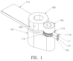
FIG. 1 schematically illustrates an isometric view of a locking confirmation device according to the first embodiment of the present invention; -
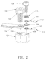
FIG. 2 schematically illustrates an exploded view of the locking confirmation device according to the first embodiment of the present invention; -
FIG. 3 schematically illustrates a sectional view of the locking confirmation device according to the first embodiment of the present invention; -
FIG. 4 schematically illustrates an isometric view of a locking confirmation device according to the second embodiment of the present invention; and -
FIG. 5 schematically illustrates a wiring configuration of multiple battery modules in parallel according to the second embodiment of the present invention. - Hereinafter, a locking confirmation device of multiple electrode contacts according to the first embodiment of the present invention will be illustrated with reference to
FIGs. 1-3 . The locking confirmation device includes anelectrode 101, aterminal bolt 102, a positioning recess 103, anelectrode thread 104, apositioning bolt 105, apositioning thread 106, a conductor 110, afirst contact 111, asecond contact 112, a first insulatedsleeve 113, a second insulatedsleeve 114, an insulated cover and anelastic spacer 116. - As shown in
FIG. 2 , the electrode includes theelectrode thread 104 and thepositioning thread 106. - The conductor 110 is locked on the
electrode 101 through theterminal bolt 102. Theterminal bolt 102 is adjusted to a position for aligning thepositioning recess 103 and thepositioning thread 106, thereby installing thepositioning bolt 105. - The
positioning bolt 105 is used for fixing a detection sensor assembly on thepositioning thread 106. - The sensing unit includes the
insulated cover 115, thefirst contact 111, thesecond contact 112 and theelastic spacer 116. As shown inFIG. 3 and illustrated in the first embodiment, the insulatedcover 115 includes thefirst contact 111 and thesecond contact 112. When the insulatedcover 115 is extruded by thepositioning bolt 105, theelastic spacer 116 is compressed, such that thefirst contact 111 and thesecond contact 112 are contacted with each other, thereby forming a conducting circuit. When the insulatedcover 115 is released or decompressed, theelastic spacer 116 will separate thefirst contact 111 and thesecond contact 112, such that the circuit between thefirst contact 111 and thesecond contact 112 is isolated. - In the first embodiment, the
first contact 111 is connected to a battery management unit, and thesecond contact 112 is connected to a voltage detecting probe or a voltage detecting connector, which is used for receiving a voltage signal from the electrode. Therefore, a stable voltage signal is continuously received by the battery management unit when thefirst contact 111 is contacted with thesecond contact 112, and the voltage signal will be lost when thefirst contact 111 and thesecond contact 112 are isolated. - Please refer to
FIG. 4 . A locking confirmation device of multiple electrode contacts according to the second embodiment of the present invention will be illustrated. Multiple detection sensor assemblies are installed to a first battery 401 and a second battery 402. The first battery 401 and the second battery 402 are connected in parallel. - The second embodiment discloses a method of detecting the locking states of multiple electrodes by transmitting a voltage signal through multiple detection sensor assemblies when two batteries are connected in parallel. The
negative electrode 412 of thefirst battery 410 and thenegative electrode 421 of thesecond battery 420 have the same potential. - A
positioning bolt 414 is used for confirming the locking state of anelectrode thread 413 of thenegative electrode 412 of thefirst battery 410. It is characterized in that a detection sensor assembly is also fixed on thepositioning bolt 414, and installed on the positioning thread of thenegative electrode 412 of thefirst battery 410 as described in the first embodiment. - A
positioning bolt 424 is used for confirming the locking state of anelectrode thread 423 of thenegative electrode 421 of thesecond battery 420. It is characterized in that a detection sensor assembly is also fixed on thepositioning bolt 414, and installed on the positioning thread of thenegative electrode 421 of thesecond battery 420 as described in the first embodiment. - A voltage information signal from the
negative electrode 412 of thefirst battery 410 and thenegative electrode 421 of thesecond battery 420 are transmitted to aconductor 450 and aninput wire 452. When this two detection sensor assemblies related with thepositioning bolt 414 and thepositioning bolt 424 are extruded that makes a current passing through a first contact and a second contact, the current information signal is transmitted, through theinput wire 452, an interconnectingwire 451, and anoutput wire 453 of a battery management unit (not shown), to the battery management unit for returning the voltage information. - When a related positioning bolt of one of the detection sensor assemblies is loosened, the extruded state will be lost, such that the electric conduction between the first contact and the second contact will be broken. Under this circumstance, the battery management unit will lose the voltage information signal. Therefore, the loss of the voltage information signal can be utilized as an indication of loosening possibility of the electrode contacts by a vehicle management unit, and the vehicle management unit related with the battery management unit can notice a user or a service officer to operate a necessary detection on the electrode contacts.
- Please refer to
FIG. 5 . The advanced examples of the second embodiment are illustrated inFIG. 5 .Blocks Wires - As shown in
FIG. 5 ,bias resistors wires 520 and 534, and all voltage values of the nodes of the electrodes are obtained by the battery management unit. When one of the detection sensor assembly is loosened, the electric connection between thewires 520 and 534 is not conducted, the voltage information signal of nodes of the electrodes can be read by the battery management unit through the corresponding bias resistors and a reduced voltage value is obtained by the battery management unit. Therefore, the fault electrodes with fault electrode contact can be determined and identified through the reduced voltage signal and the calculation of the voltage value of the voltage divider circuit by the vehicle management unit related with the battery management unit. - Through the implementation of the embodiment shown in
FIG. 5 , the fault electrode contacts can be noticed to the user by the vehicle management unit before the loosening of an electrode or a conductor. Since the loosened positioning bolt is identified through the reduced voltage signal by the vehicle management unit, the terminal bolt is still located in the electrode thread. That is, it provides a warning of detecting fault electrode contacts to the driver or the service officer.
Claims (5)
- A locking confirmation device of multiple electrode contacts, the locking confirmation device comprising:an electrode comprising an electrode thread and a positioning thread;a terminal bolt for locking a conductor and the electrode thread, wherein the terminal bolt comprises at least one positioning recess;a sensing unit comprising an insulated cover, a first contact, a second contact, an elastic member and an voltage signal input connector, wherein when the elastic member is extruded, a circuit is formed for returning a voltage signal of a node of the electrode; anda positioning bolt for fixing a detection sensor assembly on the positioning thread, wherein when a head portion of the positioning bolt is received within the positioning recess, the terminal bolt is led to a locking state by the head portion of the positioning bolt.
- The locking confirmation device of multiple electrode contacts according to claim 1 further comprising an extra detection sensor assembly of an extra electrode, wherein the extra electrode and the electrode have the same potential.
- The locking confirmation device of multiple electrode contacts according to claim 2 further comprising at least a bias resistor for forming a voltage divider circuit, wherein when the elastic member is not extruded, an unique drop voltage signal is transmitted to a battery management component.
- The locking confirmation device of multiple electrode contacts according to claim 3 further comprising a control unit for identifying fault electrode contacts through measuring the unique drop voltage signal.
- A locking confirmation device for detecting fault electrode contacts of nodes of multiple electrodes comprising at least two detection sensor assemblies and a voltage signal input connector, wherein each detection sensor assembly comprises an insulation assembly, a first contact, a second contact and an elastic member, and wherein when the elastic member is extruded by a locking of a positioning bolt and a related terminal bolt, a circuit is formed for conducting the first contact and the second contact.
Applications Claiming Priority (1)
| Application Number | Priority Date | Filing Date | Title |
|---|---|---|---|
| PCT/CN2013/085338 WO2015054852A1 (en) | 2013-10-16 | 2013-10-16 | Detection apparatus for detecting locked states of multiple electrodes by using battery sensor |
Publications (3)
| Publication Number | Publication Date |
|---|---|
| EP3059797A1 true EP3059797A1 (en) | 2016-08-24 |
| EP3059797A4 EP3059797A4 (en) | 2017-07-19 |
| EP3059797B1 EP3059797B1 (en) | 2020-04-01 |
Family
ID=52827556
Family Applications (1)
| Application Number | Title | Priority Date | Filing Date |
|---|---|---|---|
| EP13895480.5A Active EP3059797B1 (en) | 2013-10-16 | 2013-10-16 | Detection apparatus for detecting locked states of multiple electrodes by using battery sensor |
Country Status (7)
| Country | Link |
|---|---|
| US (1) | US9880216B2 (en) |
| EP (1) | EP3059797B1 (en) |
| JP (1) | JP6195669B2 (en) |
| KR (1) | KR101858882B1 (en) |
| CN (1) | CN105659427B (en) |
| CA (1) | CA2927508C (en) |
| WO (1) | WO2015054852A1 (en) |
Families Citing this family (3)
| Publication number | Priority date | Publication date | Assignee | Title |
|---|---|---|---|---|
| KR102584585B1 (en) * | 2018-02-13 | 2023-10-05 | 현대모비스 주식회사 | Battery management system with detection function of locking state |
| CN108896285B (en) * | 2018-06-08 | 2020-12-25 | 远景能源有限公司 | Fastener monitoring device |
| CN112363084B (en) * | 2019-07-26 | 2024-05-07 | 浙江吉智新能源汽车科技有限公司 | A battery locking mechanism state detection device, method and vehicle |
Family Cites Families (34)
| Publication number | Priority date | Publication date | Assignee | Title |
|---|---|---|---|---|
| US2449057A (en) * | 1945-04-14 | 1948-09-14 | Bell Telephone Labor Inc | Electrical testing device |
| JPS6039523A (en) * | 1983-08-12 | 1985-03-01 | Yahata Tekko Kk | Detecting method of looseness in fastening part |
| JPH056547Y2 (en) * | 1986-08-28 | 1993-02-19 | ||
| US4773272A (en) * | 1986-11-25 | 1988-09-27 | Trungold Emanuel H | Apparatus and method for measuring bolt tension in situ |
| JPH07109840B2 (en) * | 1989-03-10 | 1995-11-22 | 松下電器産業株式会社 | Semiconductor IC test apparatus and test method |
| JPH0668977B2 (en) * | 1989-08-03 | 1994-08-31 | 矢崎総業株式会社 | Press-contact terminal and detection device for incorrect insertion of the press-contact terminal into the housing |
| JP2871332B2 (en) * | 1992-09-03 | 1999-03-17 | 住友電装株式会社 | Connector inspection device |
| JP2586317Y2 (en) * | 1993-08-30 | 1998-12-02 | 矢崎総業株式会社 | Terminal inspection tool |
| JPH09199107A (en) * | 1996-01-12 | 1997-07-31 | Nissan Motor Co Ltd | Battery terminal surface pressure defect prevention device and method |
| JP3365602B2 (en) * | 1996-05-09 | 2003-01-14 | トヨタ自動車株式会社 | Control method of battery output of electric vehicle and terminal connection structure of battery used for the method |
| DE19831372C2 (en) * | 1998-07-13 | 2003-04-24 | Fraunhofer Ges Forschung | Device for checking non-positive connections |
| JP4183393B2 (en) * | 2000-05-23 | 2008-11-19 | 本田技研工業株式会社 | Battery connection jig and finished vehicle inspection method |
| JP3985182B2 (en) * | 2000-11-01 | 2007-10-03 | 住友電装株式会社 | Battery terminal with current sensor |
| WO2007119682A1 (en) * | 2006-04-13 | 2007-10-25 | Panasonic Corporation | Battery pack and method for detecting disconnection of same |
| WO2008095315A1 (en) | 2007-02-09 | 2008-08-14 | Advanced Lithium Power Inc. | Battery management system |
| JP2008241421A (en) * | 2007-03-27 | 2008-10-09 | Toyota Motor Corp | Detection device for detecting the state of a fastening member and power storage mechanism provided with the detection device |
| TWI315705B (en) * | 2007-12-28 | 2009-10-11 | Ind Tech Res Inst | Workstation |
| JP5472570B2 (en) * | 2009-01-07 | 2014-04-16 | 三菱自動車工業株式会社 | Secondary battery voltage detector |
| JP5465440B2 (en) * | 2009-01-28 | 2014-04-09 | 三洋電機株式会社 | Assembled battery |
| CN101799033B (en) | 2009-02-10 | 2011-09-14 | 南通高盛机械制造有限公司 | Multistage push fastener with detection interface |
| JP4696291B2 (en) * | 2009-06-04 | 2011-06-08 | 三菱自動車工業株式会社 | Secondary battery abnormality detection device |
| FR2947670B1 (en) * | 2009-07-02 | 2016-02-26 | Valeo Equip Electr Moteur | BATTERY PITCH EQUIPPED WITH SHUNT OF BATTERY CURRENT MEASUREMENT |
| JP5723139B2 (en) * | 2010-04-30 | 2015-05-27 | 矢崎総業株式会社 | Battery terminal unit with current sensor |
| JP2011258413A (en) * | 2010-06-09 | 2011-12-22 | Auto Network Gijutsu Kenkyusho:Kk | Battery connection assembly |
| JP5145380B2 (en) * | 2010-07-06 | 2013-02-13 | 三菱重工業株式会社 | Battery system |
| KR101310733B1 (en) | 2011-01-07 | 2013-09-24 | 주식회사 엘지화학 | Apparatus and method for managing battery pack |
| CN102759906B (en) * | 2011-04-26 | 2018-05-22 | 费希尔控制国际公司 | For characterizing the method and apparatus of process control facility gate oxide integrity |
| CN202117103U (en) * | 2011-05-25 | 2012-01-18 | 三一重机有限公司 | Loosening-resistant warning device for counter weight of excavator |
| JP5739244B2 (en) | 2011-06-14 | 2015-06-24 | 矢崎総業株式会社 | Battery status notification unit, bus bar module, assembled battery, and battery status monitoring system |
| CN102322983B (en) | 2011-08-05 | 2013-01-23 | 中国水利水电科学研究院机电所 | Bolt fastening state monitoring device and monitoring method thereof |
| CN202495555U (en) | 2012-02-16 | 2012-10-17 | 东莞新能源电子科技有限公司 | A temperature and voltage detection device for a battery pack |
| CN202562957U (en) | 2012-03-06 | 2012-11-28 | 肇庆理士电源技术有限公司 | Detection connection device |
| CN102623767B (en) * | 2012-03-28 | 2014-09-17 | 力帆实业(集团)股份有限公司 | Battery pack high pressure connection management method |
| CN103101489A (en) | 2012-10-08 | 2013-05-15 | 天津市松正电动汽车技术股份有限公司 | Method of detecting whether connecting wires of electric automobile are loose |
-
2013
- 2013-10-16 EP EP13895480.5A patent/EP3059797B1/en active Active
- 2013-10-16 US US15/029,864 patent/US9880216B2/en not_active Expired - Fee Related
- 2013-10-16 CA CA2927508A patent/CA2927508C/en not_active Expired - Fee Related
- 2013-10-16 JP JP2016523911A patent/JP6195669B2/en not_active Expired - Fee Related
- 2013-10-16 KR KR1020167012631A patent/KR101858882B1/en not_active Expired - Fee Related
- 2013-10-16 WO PCT/CN2013/085338 patent/WO2015054852A1/en not_active Ceased
- 2013-10-16 CN CN201380080290.9A patent/CN105659427B/en not_active Expired - Fee Related
Also Published As
| Publication number | Publication date |
|---|---|
| CN105659427A (en) | 2016-06-08 |
| JP6195669B2 (en) | 2017-09-13 |
| CA2927508C (en) | 2019-01-22 |
| JP2017501377A (en) | 2017-01-12 |
| CN105659427B (en) | 2018-05-22 |
| WO2015054852A1 (en) | 2015-04-23 |
| KR20160071442A (en) | 2016-06-21 |
| EP3059797A4 (en) | 2017-07-19 |
| KR101858882B1 (en) | 2018-05-16 |
| US9880216B2 (en) | 2018-01-30 |
| CA2927508A1 (en) | 2015-04-23 |
| US20160252560A1 (en) | 2016-09-01 |
| EP3059797B1 (en) | 2020-04-01 |
Similar Documents
| Publication | Publication Date | Title |
|---|---|---|
| EP2782195B1 (en) | Connector and connector assembly | |
| EP3035067B1 (en) | Method and apparatus for detecting faulty contacts in battery packs | |
| JP5369833B2 (en) | Electric vehicle charger and ground fault detection method | |
| US10826138B2 (en) | Method and apparatus for contact detection in battery packs | |
| US20100148796A1 (en) | Device for checking the attachment of a circuit board on a carrier | |
| CN105637670A (en) | Locking state confirmation means of battery contact special for electric vehicle | |
| CN104823067B (en) | High voltage service disconnect assembly and method for determining isolation resistor failure of a battery pack | |
| EP3623822A1 (en) | Redundant current sampling assembly | |
| US9880216B2 (en) | Locking confirmation device of multiple electrode contacts and locking confirmation device for detecting fault electrode contacts of nodes of multiple electrodes | |
| JP2010536641A (en) | Monitoring device for monitoring the connection of connecting parts | |
| US10850618B2 (en) | Connection module for an electrical energy storage device, and power supply system | |
| US20250237562A1 (en) | Temperature Error Detection At One End Of A Cable Connection Far From The Temperature Sensor By Temperature Gradient Observation | |
| KR20150043589A (en) | Patch Panel And Patch Cord Management System Having The Same | |
| CN115915590B (en) | Printed circuit board assembly for measuring battery current in battery-powered vehicles | |
| CN219040953U (en) | Electric connector | |
| JP5886587B2 (en) | Railway signal equipment voltage measuring wire auxiliary tool and measuring method | |
| TWI479170B (en) | A locking status detection apparatus utilizing a voltage sensor assembly for multiple battery terminals | |
| CN109119706B (en) | Battery pack and battery module capable of detecting contact point | |
| CN112363084A (en) | State detection device and method of battery locking mechanism and vehicle | |
| US20250170895A1 (en) | Intelligent high voltage interlock loop with individualized detection of connector connectivity | |
| CN112217181B (en) | Power protection method and circuit for electronic device | |
| JP5137597B2 (en) | Battery connection monitoring device | |
| KR20250092857A (en) | Connector contact defect detection device and connector contact defect detection method | |
| CN114978308A (en) | Optical box flange monitor and positioning method based on optical box flange monitor | |
| JP2017191742A (en) | Terminal, connector, and connection state detection system |
Legal Events
| Date | Code | Title | Description |
|---|---|---|---|
| PUAI | Public reference made under article 153(3) epc to a published international application that has entered the european phase |
Free format text: ORIGINAL CODE: 0009012 |
|
| 17P | Request for examination filed |
Effective date: 20160517 |
|
| AK | Designated contracting states |
Kind code of ref document: A1 Designated state(s): AL AT BE BG CH CY CZ DE DK EE ES FI FR GB GR HR HU IE IS IT LI LT LU LV MC MK MT NL NO PL PT RO RS SE SI SK SM TR |
|
| AX | Request for extension of the european patent |
Extension state: BA ME |
|
| RAP1 | Party data changed (applicant data changed or rights of an application transferred) |
Owner name: ALEEES ECO ARK (CAYMAN) CO. LTD. |
|
| DAX | Request for extension of the european patent (deleted) | ||
| REG | Reference to a national code |
Ref country code: DE Ref legal event code: R079 Ref document number: 602013067558 Country of ref document: DE Free format text: PREVIOUS MAIN CLASS: H01M0010420000 Ipc: G01R0031000000 |
|
| A4 | Supplementary search report drawn up and despatched |
Effective date: 20170619 |
|
| RIC1 | Information provided on ipc code assigned before grant |
Ipc: H01M 10/42 20060101ALI20170612BHEP Ipc: G01L 1/00 20060101ALI20170612BHEP Ipc: H01M 10/48 20060101ALI20170612BHEP Ipc: G01R 31/00 20060101AFI20170612BHEP Ipc: G01R 31/04 20060101ALI20170612BHEP Ipc: H01M 2/20 20060101ALI20170612BHEP Ipc: H01M 2/30 20060101ALI20170612BHEP Ipc: G01L 5/24 20060101ALI20170612BHEP |
|
| GRAP | Despatch of communication of intention to grant a patent |
Free format text: ORIGINAL CODE: EPIDOSNIGR1 |
|
| STAA | Information on the status of an ep patent application or granted ep patent |
Free format text: STATUS: GRANT OF PATENT IS INTENDED |
|
| INTG | Intention to grant announced |
Effective date: 20191205 |
|
| GRAS | Grant fee paid |
Free format text: ORIGINAL CODE: EPIDOSNIGR3 |
|
| GRAA | (expected) grant |
Free format text: ORIGINAL CODE: 0009210 |
|
| STAA | Information on the status of an ep patent application or granted ep patent |
Free format text: STATUS: THE PATENT HAS BEEN GRANTED |
|
| AK | Designated contracting states |
Kind code of ref document: B1 Designated state(s): AL AT BE BG CH CY CZ DE DK EE ES FI FR GB GR HR HU IE IS IT LI LT LU LV MC MK MT NL NO PL PT RO RS SE SI SK SM TR |
|
| REG | Reference to a national code |
Ref country code: GB Ref legal event code: FG4D |
|
| REG | Reference to a national code |
Ref country code: CH Ref legal event code: EP Ref country code: AT Ref legal event code: REF Ref document number: 1252067 Country of ref document: AT Kind code of ref document: T Effective date: 20200415 |
|
| REG | Reference to a national code |
Ref country code: DE Ref legal event code: R096 Ref document number: 602013067558 Country of ref document: DE |
|
| REG | Reference to a national code |
Ref country code: IE Ref legal event code: FG4D |
|
| PG25 | Lapsed in a contracting state [announced via postgrant information from national office to epo] |
Ref country code: BG Free format text: LAPSE BECAUSE OF FAILURE TO SUBMIT A TRANSLATION OF THE DESCRIPTION OR TO PAY THE FEE WITHIN THE PRESCRIBED TIME-LIMIT Effective date: 20200701 |
|
| REG | Reference to a national code |
Ref country code: NL Ref legal event code: MP Effective date: 20200401 |
|
| REG | Reference to a national code |
Ref country code: LT Ref legal event code: MG4D |
|
| PG25 | Lapsed in a contracting state [announced via postgrant information from national office to epo] |
Ref country code: NL Free format text: LAPSE BECAUSE OF FAILURE TO SUBMIT A TRANSLATION OF THE DESCRIPTION OR TO PAY THE FEE WITHIN THE PRESCRIBED TIME-LIMIT Effective date: 20200401 Ref country code: SE Free format text: LAPSE BECAUSE OF FAILURE TO SUBMIT A TRANSLATION OF THE DESCRIPTION OR TO PAY THE FEE WITHIN THE PRESCRIBED TIME-LIMIT Effective date: 20200401 Ref country code: PT Free format text: LAPSE BECAUSE OF FAILURE TO SUBMIT A TRANSLATION OF THE DESCRIPTION OR TO PAY THE FEE WITHIN THE PRESCRIBED TIME-LIMIT Effective date: 20200817 Ref country code: LT Free format text: LAPSE BECAUSE OF FAILURE TO SUBMIT A TRANSLATION OF THE DESCRIPTION OR TO PAY THE FEE WITHIN THE PRESCRIBED TIME-LIMIT Effective date: 20200401 Ref country code: IS Free format text: LAPSE BECAUSE OF FAILURE TO SUBMIT A TRANSLATION OF THE DESCRIPTION OR TO PAY THE FEE WITHIN THE PRESCRIBED TIME-LIMIT Effective date: 20200801 Ref country code: CZ Free format text: LAPSE BECAUSE OF FAILURE TO SUBMIT A TRANSLATION OF THE DESCRIPTION OR TO PAY THE FEE WITHIN THE PRESCRIBED TIME-LIMIT Effective date: 20200401 Ref country code: NO Free format text: LAPSE BECAUSE OF FAILURE TO SUBMIT A TRANSLATION OF THE DESCRIPTION OR TO PAY THE FEE WITHIN THE PRESCRIBED TIME-LIMIT Effective date: 20200701 Ref country code: GR Free format text: LAPSE BECAUSE OF FAILURE TO SUBMIT A TRANSLATION OF THE DESCRIPTION OR TO PAY THE FEE WITHIN THE PRESCRIBED TIME-LIMIT Effective date: 20200702 Ref country code: FI Free format text: LAPSE BECAUSE OF FAILURE TO SUBMIT A TRANSLATION OF THE DESCRIPTION OR TO PAY THE FEE WITHIN THE PRESCRIBED TIME-LIMIT Effective date: 20200401 |
|
| REG | Reference to a national code |
Ref country code: AT Ref legal event code: MK05 Ref document number: 1252067 Country of ref document: AT Kind code of ref document: T Effective date: 20200401 |
|
| PG25 | Lapsed in a contracting state [announced via postgrant information from national office to epo] |
Ref country code: LV Free format text: LAPSE BECAUSE OF FAILURE TO SUBMIT A TRANSLATION OF THE DESCRIPTION OR TO PAY THE FEE WITHIN THE PRESCRIBED TIME-LIMIT Effective date: 20200401 Ref country code: HR Free format text: LAPSE BECAUSE OF FAILURE TO SUBMIT A TRANSLATION OF THE DESCRIPTION OR TO PAY THE FEE WITHIN THE PRESCRIBED TIME-LIMIT Effective date: 20200401 Ref country code: RS Free format text: LAPSE BECAUSE OF FAILURE TO SUBMIT A TRANSLATION OF THE DESCRIPTION OR TO PAY THE FEE WITHIN THE PRESCRIBED TIME-LIMIT Effective date: 20200401 |
|
| PG25 | Lapsed in a contracting state [announced via postgrant information from national office to epo] |
Ref country code: AL Free format text: LAPSE BECAUSE OF FAILURE TO SUBMIT A TRANSLATION OF THE DESCRIPTION OR TO PAY THE FEE WITHIN THE PRESCRIBED TIME-LIMIT Effective date: 20200401 |
|
| REG | Reference to a national code |
Ref country code: DE Ref legal event code: R097 Ref document number: 602013067558 Country of ref document: DE |
|
| PG25 | Lapsed in a contracting state [announced via postgrant information from national office to epo] |
Ref country code: IT Free format text: LAPSE BECAUSE OF FAILURE TO SUBMIT A TRANSLATION OF THE DESCRIPTION OR TO PAY THE FEE WITHIN THE PRESCRIBED TIME-LIMIT Effective date: 20200401 Ref country code: RO Free format text: LAPSE BECAUSE OF FAILURE TO SUBMIT A TRANSLATION OF THE DESCRIPTION OR TO PAY THE FEE WITHIN THE PRESCRIBED TIME-LIMIT Effective date: 20200401 Ref country code: ES Free format text: LAPSE BECAUSE OF FAILURE TO SUBMIT A TRANSLATION OF THE DESCRIPTION OR TO PAY THE FEE WITHIN THE PRESCRIBED TIME-LIMIT Effective date: 20200401 Ref country code: DK Free format text: LAPSE BECAUSE OF FAILURE TO SUBMIT A TRANSLATION OF THE DESCRIPTION OR TO PAY THE FEE WITHIN THE PRESCRIBED TIME-LIMIT Effective date: 20200401 Ref country code: AT Free format text: LAPSE BECAUSE OF FAILURE TO SUBMIT A TRANSLATION OF THE DESCRIPTION OR TO PAY THE FEE WITHIN THE PRESCRIBED TIME-LIMIT Effective date: 20200401 Ref country code: SM Free format text: LAPSE BECAUSE OF FAILURE TO SUBMIT A TRANSLATION OF THE DESCRIPTION OR TO PAY THE FEE WITHIN THE PRESCRIBED TIME-LIMIT Effective date: 20200401 Ref country code: EE Free format text: LAPSE BECAUSE OF FAILURE TO SUBMIT A TRANSLATION OF THE DESCRIPTION OR TO PAY THE FEE WITHIN THE PRESCRIBED TIME-LIMIT Effective date: 20200401 |
|
| PLBE | No opposition filed within time limit |
Free format text: ORIGINAL CODE: 0009261 |
|
| STAA | Information on the status of an ep patent application or granted ep patent |
Free format text: STATUS: NO OPPOSITION FILED WITHIN TIME LIMIT |
|
| PG25 | Lapsed in a contracting state [announced via postgrant information from national office to epo] |
Ref country code: SK Free format text: LAPSE BECAUSE OF FAILURE TO SUBMIT A TRANSLATION OF THE DESCRIPTION OR TO PAY THE FEE WITHIN THE PRESCRIBED TIME-LIMIT Effective date: 20200401 Ref country code: PL Free format text: LAPSE BECAUSE OF FAILURE TO SUBMIT A TRANSLATION OF THE DESCRIPTION OR TO PAY THE FEE WITHIN THE PRESCRIBED TIME-LIMIT Effective date: 20200401 |
|
| 26N | No opposition filed |
Effective date: 20210112 |
|
| REG | Reference to a national code |
Ref country code: DE Ref legal event code: R119 Ref document number: 602013067558 Country of ref document: DE |
|
| PG25 | Lapsed in a contracting state [announced via postgrant information from national office to epo] |
Ref country code: SI Free format text: LAPSE BECAUSE OF FAILURE TO SUBMIT A TRANSLATION OF THE DESCRIPTION OR TO PAY THE FEE WITHIN THE PRESCRIBED TIME-LIMIT Effective date: 20200401 |
|
| REG | Reference to a national code |
Ref country code: CH Ref legal event code: PL |
|
| GBPC | Gb: european patent ceased through non-payment of renewal fee |
Effective date: 20201016 |
|
| PG25 | Lapsed in a contracting state [announced via postgrant information from national office to epo] |
Ref country code: MC Free format text: LAPSE BECAUSE OF FAILURE TO SUBMIT A TRANSLATION OF THE DESCRIPTION OR TO PAY THE FEE WITHIN THE PRESCRIBED TIME-LIMIT Effective date: 20200401 Ref country code: LU Free format text: LAPSE BECAUSE OF NON-PAYMENT OF DUE FEES Effective date: 20201016 |
|
| REG | Reference to a national code |
Ref country code: BE Ref legal event code: MM Effective date: 20201031 |
|
| PG25 | Lapsed in a contracting state [announced via postgrant information from national office to epo] |
Ref country code: FR Free format text: LAPSE BECAUSE OF NON-PAYMENT OF DUE FEES Effective date: 20201031 Ref country code: DE Free format text: LAPSE BECAUSE OF NON-PAYMENT OF DUE FEES Effective date: 20210501 |
|
| PG25 | Lapsed in a contracting state [announced via postgrant information from national office to epo] |
Ref country code: LI Free format text: LAPSE BECAUSE OF NON-PAYMENT OF DUE FEES Effective date: 20201031 Ref country code: GB Free format text: LAPSE BECAUSE OF NON-PAYMENT OF DUE FEES Effective date: 20201016 Ref country code: CH Free format text: LAPSE BECAUSE OF NON-PAYMENT OF DUE FEES Effective date: 20201031 Ref country code: BE Free format text: LAPSE BECAUSE OF NON-PAYMENT OF DUE FEES Effective date: 20201031 |
|
| PG25 | Lapsed in a contracting state [announced via postgrant information from national office to epo] |
Ref country code: IE Free format text: LAPSE BECAUSE OF NON-PAYMENT OF DUE FEES Effective date: 20201016 |
|
| PG25 | Lapsed in a contracting state [announced via postgrant information from national office to epo] |
Ref country code: TR Free format text: LAPSE BECAUSE OF FAILURE TO SUBMIT A TRANSLATION OF THE DESCRIPTION OR TO PAY THE FEE WITHIN THE PRESCRIBED TIME-LIMIT Effective date: 20200401 Ref country code: MT Free format text: LAPSE BECAUSE OF FAILURE TO SUBMIT A TRANSLATION OF THE DESCRIPTION OR TO PAY THE FEE WITHIN THE PRESCRIBED TIME-LIMIT Effective date: 20200401 Ref country code: CY Free format text: LAPSE BECAUSE OF FAILURE TO SUBMIT A TRANSLATION OF THE DESCRIPTION OR TO PAY THE FEE WITHIN THE PRESCRIBED TIME-LIMIT Effective date: 20200401 |
|
| PG25 | Lapsed in a contracting state [announced via postgrant information from national office to epo] |
Ref country code: MK Free format text: LAPSE BECAUSE OF FAILURE TO SUBMIT A TRANSLATION OF THE DESCRIPTION OR TO PAY THE FEE WITHIN THE PRESCRIBED TIME-LIMIT Effective date: 20200401 |