EP3059522A2 - Transport refrigeration unit - Google Patents
Transport refrigeration unit Download PDFInfo
- Publication number
- EP3059522A2 EP3059522A2 EP16155458.9A EP16155458A EP3059522A2 EP 3059522 A2 EP3059522 A2 EP 3059522A2 EP 16155458 A EP16155458 A EP 16155458A EP 3059522 A2 EP3059522 A2 EP 3059522A2
- Authority
- EP
- European Patent Office
- Prior art keywords
- heat exchangers
- outside
- heat exchanger
- pressure
- outside heat
- Prior art date
- Legal status (The legal status is an assumption and is not a legal conclusion. Google has not performed a legal analysis and makes no representation as to the accuracy of the status listed.)
- Withdrawn
Links
- 238000005057 refrigeration Methods 0.000 title claims abstract description 65
- 238000010257 thawing Methods 0.000 claims abstract description 74
- 239000003507 refrigerant Substances 0.000 claims abstract description 72
- 238000010792 warming Methods 0.000 claims abstract description 47
- 238000001816 cooling Methods 0.000 claims abstract description 33
- 238000004891 communication Methods 0.000 claims description 8
- 239000007788 liquid Substances 0.000 description 15
- 238000010438 heat treatment Methods 0.000 description 11
- 238000000034 method Methods 0.000 description 11
- 238000010586 diagram Methods 0.000 description 6
- 230000004048 modification Effects 0.000 description 6
- 238000012986 modification Methods 0.000 description 6
- 230000009471 action Effects 0.000 description 5
- 230000008859 change Effects 0.000 description 5
- 238000004378 air conditioning Methods 0.000 description 4
- 230000003247 decreasing effect Effects 0.000 description 3
- 230000008569 process Effects 0.000 description 3
- 230000002159 abnormal effect Effects 0.000 description 2
- 230000007257 malfunction Effects 0.000 description 2
- 230000000694 effects Effects 0.000 description 1
- 238000009413 insulation Methods 0.000 description 1
- 238000012544 monitoring process Methods 0.000 description 1
Images




Classifications
-
- F—MECHANICAL ENGINEERING; LIGHTING; HEATING; WEAPONS; BLASTING
- F25—REFRIGERATION OR COOLING; COMBINED HEATING AND REFRIGERATION SYSTEMS; HEAT PUMP SYSTEMS; MANUFACTURE OR STORAGE OF ICE; LIQUEFACTION SOLIDIFICATION OF GASES
- F25B—REFRIGERATION MACHINES, PLANTS OR SYSTEMS; COMBINED HEATING AND REFRIGERATION SYSTEMS; HEAT PUMP SYSTEMS
- F25B47/00—Arrangements for preventing or removing deposits or corrosion, not provided for in another subclass
- F25B47/02—Defrosting cycles
- F25B47/022—Defrosting cycles hot gas defrosting
- F25B47/025—Defrosting cycles hot gas defrosting by reversing the cycle
-
- F—MECHANICAL ENGINEERING; LIGHTING; HEATING; WEAPONS; BLASTING
- F25—REFRIGERATION OR COOLING; COMBINED HEATING AND REFRIGERATION SYSTEMS; HEAT PUMP SYSTEMS; MANUFACTURE OR STORAGE OF ICE; LIQUEFACTION SOLIDIFICATION OF GASES
- F25B—REFRIGERATION MACHINES, PLANTS OR SYSTEMS; COMBINED HEATING AND REFRIGERATION SYSTEMS; HEAT PUMP SYSTEMS
- F25B13/00—Compression machines, plants or systems, with reversible cycle
-
- F—MECHANICAL ENGINEERING; LIGHTING; HEATING; WEAPONS; BLASTING
- F25—REFRIGERATION OR COOLING; COMBINED HEATING AND REFRIGERATION SYSTEMS; HEAT PUMP SYSTEMS; MANUFACTURE OR STORAGE OF ICE; LIQUEFACTION SOLIDIFICATION OF GASES
- F25B—REFRIGERATION MACHINES, PLANTS OR SYSTEMS; COMBINED HEATING AND REFRIGERATION SYSTEMS; HEAT PUMP SYSTEMS
- F25B49/00—Arrangement or mounting of control or safety devices
- F25B49/02—Arrangement or mounting of control or safety devices for compression type machines, plants or systems
-
- F—MECHANICAL ENGINEERING; LIGHTING; HEATING; WEAPONS; BLASTING
- F25—REFRIGERATION OR COOLING; COMBINED HEATING AND REFRIGERATION SYSTEMS; HEAT PUMP SYSTEMS; MANUFACTURE OR STORAGE OF ICE; LIQUEFACTION SOLIDIFICATION OF GASES
- F25B—REFRIGERATION MACHINES, PLANTS OR SYSTEMS; COMBINED HEATING AND REFRIGERATION SYSTEMS; HEAT PUMP SYSTEMS
- F25B2313/00—Compression machines, plants or systems with reversible cycle not otherwise provided for
- F25B2313/023—Compression machines, plants or systems with reversible cycle not otherwise provided for using multiple indoor units
- F25B2313/0231—Compression machines, plants or systems with reversible cycle not otherwise provided for using multiple indoor units with simultaneous cooling and heating
-
- F—MECHANICAL ENGINEERING; LIGHTING; HEATING; WEAPONS; BLASTING
- F25—REFRIGERATION OR COOLING; COMBINED HEATING AND REFRIGERATION SYSTEMS; HEAT PUMP SYSTEMS; MANUFACTURE OR STORAGE OF ICE; LIQUEFACTION SOLIDIFICATION OF GASES
- F25B—REFRIGERATION MACHINES, PLANTS OR SYSTEMS; COMBINED HEATING AND REFRIGERATION SYSTEMS; HEAT PUMP SYSTEMS
- F25B2313/00—Compression machines, plants or systems with reversible cycle not otherwise provided for
- F25B2313/025—Compression machines, plants or systems with reversible cycle not otherwise provided for using multiple outdoor units
- F25B2313/0251—Compression machines, plants or systems with reversible cycle not otherwise provided for using multiple outdoor units being defrosted alternately
-
- F—MECHANICAL ENGINEERING; LIGHTING; HEATING; WEAPONS; BLASTING
- F25—REFRIGERATION OR COOLING; COMBINED HEATING AND REFRIGERATION SYSTEMS; HEAT PUMP SYSTEMS; MANUFACTURE OR STORAGE OF ICE; LIQUEFACTION SOLIDIFICATION OF GASES
- F25B—REFRIGERATION MACHINES, PLANTS OR SYSTEMS; COMBINED HEATING AND REFRIGERATION SYSTEMS; HEAT PUMP SYSTEMS
- F25B2313/00—Compression machines, plants or systems with reversible cycle not otherwise provided for
- F25B2313/025—Compression machines, plants or systems with reversible cycle not otherwise provided for using multiple outdoor units
- F25B2313/0253—Compression machines, plants or systems with reversible cycle not otherwise provided for using multiple outdoor units in parallel arrangements
- F25B2313/02533—Compression machines, plants or systems with reversible cycle not otherwise provided for using multiple outdoor units in parallel arrangements during heating
-
- F—MECHANICAL ENGINEERING; LIGHTING; HEATING; WEAPONS; BLASTING
- F25—REFRIGERATION OR COOLING; COMBINED HEATING AND REFRIGERATION SYSTEMS; HEAT PUMP SYSTEMS; MANUFACTURE OR STORAGE OF ICE; LIQUEFACTION SOLIDIFICATION OF GASES
- F25B—REFRIGERATION MACHINES, PLANTS OR SYSTEMS; COMBINED HEATING AND REFRIGERATION SYSTEMS; HEAT PUMP SYSTEMS
- F25B2313/00—Compression machines, plants or systems with reversible cycle not otherwise provided for
- F25B2313/025—Compression machines, plants or systems with reversible cycle not otherwise provided for using multiple outdoor units
- F25B2313/0254—Compression machines, plants or systems with reversible cycle not otherwise provided for using multiple outdoor units in series arrangements
- F25B2313/02542—Compression machines, plants or systems with reversible cycle not otherwise provided for using multiple outdoor units in series arrangements during defrosting
-
- F—MECHANICAL ENGINEERING; LIGHTING; HEATING; WEAPONS; BLASTING
- F25—REFRIGERATION OR COOLING; COMBINED HEATING AND REFRIGERATION SYSTEMS; HEAT PUMP SYSTEMS; MANUFACTURE OR STORAGE OF ICE; LIQUEFACTION SOLIDIFICATION OF GASES
- F25B—REFRIGERATION MACHINES, PLANTS OR SYSTEMS; COMBINED HEATING AND REFRIGERATION SYSTEMS; HEAT PUMP SYSTEMS
- F25B2313/00—Compression machines, plants or systems with reversible cycle not otherwise provided for
- F25B2313/027—Compression machines, plants or systems with reversible cycle not otherwise provided for characterised by the reversing means
- F25B2313/02791—Compression machines, plants or systems with reversible cycle not otherwise provided for characterised by the reversing means using shut-off valves
-
- F—MECHANICAL ENGINEERING; LIGHTING; HEATING; WEAPONS; BLASTING
- F25—REFRIGERATION OR COOLING; COMBINED HEATING AND REFRIGERATION SYSTEMS; HEAT PUMP SYSTEMS; MANUFACTURE OR STORAGE OF ICE; LIQUEFACTION SOLIDIFICATION OF GASES
- F25B—REFRIGERATION MACHINES, PLANTS OR SYSTEMS; COMBINED HEATING AND REFRIGERATION SYSTEMS; HEAT PUMP SYSTEMS
- F25B2500/00—Problems to be solved
- F25B2500/15—Hunting, i.e. oscillation of controlled refrigeration variables reaching undesirable values
-
- F—MECHANICAL ENGINEERING; LIGHTING; HEATING; WEAPONS; BLASTING
- F25—REFRIGERATION OR COOLING; COMBINED HEATING AND REFRIGERATION SYSTEMS; HEAT PUMP SYSTEMS; MANUFACTURE OR STORAGE OF ICE; LIQUEFACTION SOLIDIFICATION OF GASES
- F25B—REFRIGERATION MACHINES, PLANTS OR SYSTEMS; COMBINED HEATING AND REFRIGERATION SYSTEMS; HEAT PUMP SYSTEMS
- F25B2600/00—Control issues
- F25B2600/02—Compressor control
- F25B2600/025—Compressor control by controlling speed
- F25B2600/0251—Compressor control by controlling speed with on-off operation
Definitions
- the present invention relates to a transport refrigeration unit having a heat pump-type warming function and mounted on a refrigerated vehicle, a trailer, or the like.
- a transport refrigeration unit having a heat pump-type warming function has been provided. Examples thereof are described in PTLs 1 and 2.
- one end sides of a plurality of heat exchangers are connected to a discharge side of a compressor each via a high-pressure gas pipe and a high-pressure on-off valve, and the one end sides of the plurality of heat exchangers are connected to a suction side of the compressor each via a low-pressure gas pipe and a low-pressure on-off valve.
- Liquid-side pipes including parallel circuits each having a pressure reducing means with an on-off valve function (a means in which an on-off valve and an expansion valve are connected in series with each other, a means using an electric expansion valve having an on-off valve function, etc.) and a check valve are connected to the other end sides of the respective heat exchangers.
- the liquid-side pipes are connected together in communication. A refrigerant circuit is thereby configured.
- One of the plurality of heat exchangers is disposed outside a refrigerator as an outside heat exchanger.
- One or more of the heat exchangers are disposed inside the refrigerator as an inside heat exchanger.
- a refrigerant flow into the respective heat exchangers is switched by opening or closing the respective high-pressure on-off valves provided in the high-pressure gas pipes, the respective low-pressure on-off valves provided in the low-pressure gas pipes, and the on-off valve functions of the respective pressure reducing means with an on-off valve function provided in the liquid-side pipes.
- a cooling operation is performed by causing the outside heat exchanger to function as a condenser, and the inside heat exchanger to function as an evaporator.
- a heat pump warming operation is performed by causing the inside heat exchanger to function as a condenser, and the outside heat exchanger to function as an evaporator.
- PTLs 3 and 4 disclose a multi-type air-conditioning apparatus, that is, a so-called cooling/heating free multi-type air-conditioning apparatus that can perform a cooling/heating simultaneous operation by employing a refrigerant circuit similar to the above circuit.
- a plurality of outdoor heat exchangers are disposed in parallel with each other.
- the frosted plurality of outdoor heat exchangers are alternately defrosted by causing one of the outdoor heat exchangers to function as an evaporator, and another one to function as a condenser while continuing the heating operation by causing a hot gas refrigerant to flow through an indoor heat exchanger.
- the present invention has been made in view of the above circumstances, and an object thereof is to provide a transport refrigeration unit employing a heat pump warming method, which can prevent a decrease in an inside temperature during defrosting, can perform defrosting within a short time, and can ensure reliability by appropriately adjusting a condensing capacity during a cooling operation, and suppressing frequent starting and stopping of a compressor during thermo-on/off.
- a transport refrigeration unit includes: a compressor; a plurality of heat exchangers, one end sides of which are connected to a discharge side of the compressor each via a high-pressure gas pipe and a high-pressure on-off valve; low-pressure gas pipes that connect the one end sides of the plurality of heat exchangers to a suction side of the compressor each via a low-pressure on-off valve; and liquid-side pipes that connect together in communication the other end sides of parallel circuits connected to the other end sides of the plurality of heat exchangers and each having a pressure reducing means with an on-off valve function and a check valve, wherein at least two of the plurality of heat exchangers are disposed in parallel with each other outside a refrigerator as outside heat exchangers, at least one of the plurality of heat exchangers is disposed inside the refrigerator as an inside heat exchanger, and when the outside heat exchangers are frosted during a heat pump warming operation in which the outside heat exchangers are caused to function as evaporators
- the one end sides of the plurality of heat exchangers connected to the discharge side of the compressor each via the high-pressure gas pipe and the high-pressure on-off valve are connected to the suction side of the compressor each via the low-pressure gas pipe and the low-pressure on-off valve.
- the liquid-side pipes including the parallel circuits each having the pressure reducing means with an on-off valve function and the check valve are connected to the other end sides of the plurality of heat exchangers, and the other end sides of the liquid-side pipes are connected together in communication. Accordingly, a refrigerant circuit is configured.
- At least two of the plurality of heat exchangers are disposed in parallel with each other outside the refrigerator as the outside heat exchangers, and at least one of the plurality of heat exchangers is disposed inside the refrigerator as the inside heat exchanger. Therefore, a cooling operation for cooling the inside of the refrigerator can be performed by causing the two outside heat exchangers disposed outside the refrigerator to function as condensers, and the single inside heat exchanger disposed inside the refrigerator to function as an evaporator.
- the heat pump warming operation for warming the inside of the refrigerator can be also performed by causing the single inside heat exchanger disposed inside the refrigerator to function as the condenser, and the two outside heat exchangers disposed outside the refrigerator to function as the evaporators.
- the warming operation can be performed efficiently with high capacity by employing the heat pump method.
- the defrosting operation is performed by stopping the refrigerant distribution to the inside heat exchanger, and causing at least one of the plurality of outside heat exchangers to function as the condenser, and another one of the plurality of outside heat exchangers to function as the evaporator.
- all of a hot gas refrigerant discharged from the compressor can be supplied to at least one of the frosted outside heat exchangers, and another one of the outside heat exchangers can be caused to function as the evaporator, so that the defrosting operation can be performed with the refrigerant absorbing heat in the evaporator. Therefore, the defrosting of the outside heat exchangers can be performed by using the full capacity (all of the refrigerant) of the heat pump without absorbing heat from inside air, so that a defrosting operation time can be shortened, and a change in an inside temperature during the defrosting operation can be decreased.
- the plurality of outside heat exchangers may be sequentially subjected to the defrosting operation by sequentially switching the frosted plurality of outside heat exchangers such that at least one of the outside heat exchangers functions as a condenser, and another one of the outside heat exchangers functions as an evaporator.
- the plurality of outside heat exchangers are sequentially subjected to the defrosting operation by sequentially switching the frosted plurality of outside heat exchangers such that at least one of the outside heat exchangers functions as the condenser, and another one of the outside heat exchangers functions as the evaporator.
- a refrigerant flow between the plurality of outside heat exchangers is switched by opening or closing the high-pressure on-off valves in the high-pressure gas pipes, the low-pressure on-off valves in the low-pressure gas pipes, and the on-off valve functions of the pressure reducing means with an on-off valve function in the parallel circuits of the liquid-side pipes, which are connected to the respective outside heat exchangers, so that the plurality of outside heat exchangers can be sequentially subjected to the defrosting operation. Therefore, the plurality of outside heat exchangers can be alternately defrosted by using the full capacity (all of the refrigerant) of the heat pump. Thus, the defrosting can be performed within a short time.
- air blow systems including outside fans for the plurality of outside heat exchangers may be provided independently of each other.
- the air blow systems including the outside fans for the plurality of outside heat exchangers are provided independently of each other. Therefore, the defrosting operation can be performed by stopping an outside fan for the outside heat exchanger that functions as the condenser, and operating an outside fan for the outside heat exchanger that functions as the evaporator, during the defrosting operation. Consequently, it is possible to efficiently perform the defrosting within a short time by increasing an amount of heat absorbed in the outside heat exchanger that functions as the evaporator, and dissipating the heat in the outside heat exchanger to be defrosted.
- the warming operation when a difference between an inside temperature and a set temperature has a specified value or more during the defrosting operation, the warming operation may be performed by opening the high-pressure on-off valve in the high-pressure gas pipe connected to the inside heat exchanger, and distributing a high-pressure gas refrigerant to the inside heat exchanger.
- the warming operation when the difference between the inside temperature and the set temperature has the specified value or more during the defrosting operation, the warming operation may be performed by opening the high-pressure on-off valve in the high-pressure gas pipe connected to the inside heat exchanger, and distributing the high-pressure gas refrigerant to the inside heat exchanger. Therefore, even when the inside temperature rapidly changes due to some reason during the defrosting operation and the difference with the set temperature exceeds the specified value, it is possible to perform the warming operation while continuing the defrosting operation by partly introducing the hot gas refrigerant from the compressor into the inside heat exchanger only by opening the high-pressure on-off valve. Consequently, the inside temperature is not lowered to a specified value or less during the defrosting operation, a quality of a load can be guaranteed by keeping temperature controllability even during the defrosting, and reliability of the transport refrigeration unit can be improved.
- the condensing capacity may be adjusted by reducing the operation number of the plurality of outside heat exchangers.
- the condensing capacity is adjusted by reducing the operation number of the plurality of outside heat exchangers. Therefore, for example, in a case in which the cooling operation is performed under a condition in which an outside air temperature is relatively low, the condensing capacity becomes excessive with respect to a heat exchange amount of the inside heat exchanger when all of the plurality of outside heat exchangers are operated. Thus, a pressure in a high pressure-side circuit is lowered, and a differential pressure between high and low pressures becomes too small to deviate from a flow rate adjustable range of an expansion valve.
- An abnormal suction pressure of the compressor may be thereby caused.
- the condensing capacity is adjusted by reducing the operation number of the plurality of outside heat exchangers.
- the differential pressure between the high and low pressures can be maintained within an appropriate range. Therefore, it is possible to stably operate the transport refrigeration unit by appropriately adjusting the capacity on the outside heat exchanger-side corresponding to the heat exchange amount of the inside heat exchanger, and thereby keeping an operation balance.
- heat exchangers having different capacities from each other may be employed as the plurality of outside heat exchangers.
- the heat exchangers having different capacities from each other are employed as the plurality of outside heat exchangers.
- the condensing capacity in the plurality of outside heat exchangers in multi-stages greater than the number of the outside heat exchangers by selecting working statuses of the heat exchangers. Therefore, the condensing capacity can be finely adjusted under various outside air temperatures and inside set temperature conditions corresponding to the conditions, and the operation can be more stably performed by maintaining the high and low pressure difference within an appropriate range. Consequently, it is possible to improve the reliability of the transport refrigeration unit.
- a transport refrigeration unit includes: a compressor; a plurality of heat exchangers, one end sides of which are connected to a discharge side of the compressor each via a high-pressure gas pipe and a high-pressure on-off valve; low-pressure gas pipes that connect the one end sides of the plurality of heat exchangers to a suction side of the compressor each via a low-pressure on-off valve; and liquid-side pipes that connect together in communication the other end sides of parallel circuits connected to the other end sides of the plurality of heat exchangers and each having a pressure reducing means with an on-off valve function and a check valve, wherein at least two of the plurality of heat exchangers are disposed in parallel with each other outside a refrigerator as outside heat exchangers, at least one of the plurality of heat exchangers is disposed inside the refrigerator as an inside heat exchanger, and when an operation time of the compressor is a specified time or less during thermo-off after an inside temperature reaches a set temperature, the compressor is continuously operated until
- the one end sides of the plurality of heat exchangers connected to the discharge side of the compressor each via the high-pressure gas pipe and the high-pressure on-off valve are connected to the suction side of the compressor each via the low-pressure gas pipe and the low-pressure on-off valve.
- the liquid-side pipes including the parallel circuits each having the pressure reducing means with an on-off valve function and the check valve are connected to the other end sides of the plurality of heat exchangers, and the other end sides of the liquid-side pipes are connected together in communication. Accordingly, a refrigerant circuit is configured.
- At least two of the plurality of heat exchangers are disposed in parallel with each other outside the refrigerator as the outside heat exchangers, and at least one of the plurality of heat exchangers is disposed inside the refrigerator as the inside heat exchanger. Therefore, a cooling operation for cooling the inside of the refrigerator can be performed by causing the two outside heat exchangers disposed outside the refrigerator to function as condensers, and the single inside heat exchanger disposed inside the refrigerator to function as an evaporator.
- the heat pump warming operation for warming the inside of the refrigerator can be also performed by causing the single inside heat exchanger disposed inside the refrigerator to function as the condenser, and the two outside heat exchangers disposed outside the refrigerator to function as the evaporators.
- thermo-on/off are normally repeated. In this case, if the thermo-on/off are performed within a short time, starting and stopping of the compressor are frequently repeated, resulting in a malfunction and a decrease in service life.
- the operation time of the compressor is the specified time or less during the thermo-off, the compressor is continuously operated until the operation time exceeds the specified time by stopping the refrigerant distribution to the inside heat exchanger, and causing one of the plurality of outside heat exchangers to function as the condenser, and another one of the plurality of outside heat exchangers to function as the evaporator.
- the frequent starting and stopping of the compressor can be prevented by continuously operating the compressor until the operation time of the compressor exceeds the specified time during the thermo-off, and idling the refrigeration unit by using one of the plurality of outside heat exchangers as the condenser, and another one as the evaporator. Therefore, start/stop frequency of the compressor can be suppressed, and the reliability can be ensured.
- the cooling operation for cooling the inside of the refrigerator can be performed by causing the two outside heat exchangers disposed outside the refrigerator to function as the condensers, and the single inside heat exchanger disposed inside the refrigerator to function as the evaporator.
- the heat pump warming operation for warming the inside of the refrigerator can be also performed by causing the single inside heat exchanger disposed inside the refrigerator to function as the condenser, and the two outside heat exchangers disposed outside the refrigerator to function as the evaporators. Therefore, the warming operation can be performed efficiently with high capacity by employing the heat pump method.
- all of the hot gas refrigerant discharged from the compressor can be supplied to at least one of the frosted outside heat exchangers, and another one of the outside heat exchangers can be caused to function as the evaporator, so that the defrosting operation can be performed with the refrigerant absorbing heat in the evaporator. Therefore, the defrosting of the outside heat exchangers can be performed by using the full capacity (all of the refrigerant) of the heat pump without absorbing heat from inside air, so that the defrosting operation time can be shortened, and a change in the inside temperature during the defrosting operation can be decreased.
- the frequent starting and stopping of the compressor can be prevented by continuously operating the compressor until the operation time of the compressor exceeds the specified time during the thermo-off, and idling the refrigeration unit by using one of the plurality of outside heat exchangers as the condenser, and another one as the evaporator. Therefore, the start/stop frequency of the compressor can be suppressed, and the reliability can be ensured.
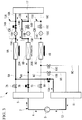
- Fig. 1 shows a refrigerant circuit diagram of a transport refrigeration unit according to the first embodiment of the present invention.
- Figs. 2 and 3 show configuration diagrams of a refrigerant circuit during the defrosting operation.
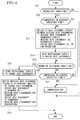
- Fig. 4 shows a control flowchart of the defrosting operation.
- the present invention is applied to an integrated transport refrigeration unit 1 that cools or warms the inside of a refrigerator called a van body that is mounted on a bed side of a refrigerated vehicle or the like.
- the present invention is not necessarily limited to the integrated transport refrigeration unit, and it goes without saying that the present invention can be widely applied to general transport refrigeration units
- a refrigerant circuit 2 of the transport refrigeration unit 1 includes a compressor 3 (here, a motor-driven compressor is employed), a high-pressure gas port 5 that is connected to a discharge pipe 4 of the compressor 3, a plurality of (three in the present example) high-pressure gas pipes 6A, 6B, and 6C that branch from the high-pressure gas port 5, high-pressure on-off valves (solenoid valves) 7A, 7B, and 7C that are provided in the high-pressure gas pipes 6A, 6B, and 6C, respectively, and a plurality of heat exchangers 8A, 8B, and 8C, one end sides of which are connected to the high-pressure gas pipes 6A, 6B, and 6C, respectively.
- a compressor 3 here, a motor-driven compressor is employed
- a high-pressure gas port 5 that is connected to a discharge pipe 4 of the compressor 3
- a plurality of (three in the present example) high-pressure gas pipes 6A, 6B, and 6C that branch from the high-
- Two heat exchangers 8A and 8B out of the plurality of heat exchangers 8A, 8B, and 8C are disposed at an outer portion of the refrigerator, that is, outside the refrigerator as an outside heat exchanger (A)8A and an outside heat exchanger (B)8B, respectively.
- the remaining one is disposed inside the refrigerator as an inside heat exchanger 8C.
- the low-pressure gas port 11 is connected to the compressor 3 via a suction pipe 12.
- one ends of parallel circuits 13A, 13B, and 13C that are configured by connecting series circuits of expansion valves 15A, 15B, and 15C and on-off valves (solenoid valves) 16A, 16B, and 16C, respectively, in parallel with check valves 14A, 14B, and 14C are connected to the other end sides of the outside heat exchanger (A)8A, the outside heat exchanger (B)8B, and the inside heat exchanger 8C.
- the other ends of the parallel circuits 13A, 13B, and 13C are connected to a high-pressure liquid port 17, so that liquid-side pipes 18A, 18B, and 18C that are connected together in communication are provided. Accordingly, the heat pump-type refrigerant circuit 2 having a closed cycle is configured.
- the series circuits of the expansion valves 15A, 15B, and 15C and the on-off valves (the solenoid valves) 16A, 16B, and 16C are referred to as pressure reducing means having an on-off valve function in the present invention.
- a configuration in which the expansion valve and the on-off valve (the solenoid valve) separate from each other are connected in series with each other is employed herein, a valve having an integrated configuration may be employed. Alternatively, the configuration may be substituted by an electric expansion valve having an on-off valve function.
- the "pressure reducing means having an on-off valve function" that collectively indicates the above configurations is used.
- the inside heat exchanger 8C is disposed in an inside air circulation path on a unit side so as to face the inside of the refrigerator, and the other devices are disposed on a unit body side that is installed outside the refrigerator.
- An inside fan 19 is attached to the inside heat exchanger 8C, so that inside air can be circulated through the inside heat exchanger 8C.
- Outside fans 20A and 20B are attached to the outside heat exchanger (A)8A and the outside heat exchanger (B)8B, respectively, so that independent air blow systems that blow outside air to the outside heat exchanger (A)8A and the outside heat exchanger (B)8B are configured.
- the high-pressure gas port 5, the low-pressure gas port 11, and the high-pressure liquid port 17 may be omitted by directly connecting the high-pressure gas pipes 6A, 6B, and 6C to the discharge pipe 4, the low-pressure gas pipes 9A, 9B, and 9C to the suction pipe 12, and the liquid-side pipes 18A, 18B, and 18C together, respectively.
- the high-pressure liquid port 17 may be substituted by a receiver.
- a cooling operation and a heat pump warming operation are performed as described below.
- the cooling operation is an operation performed by causing each of the outside heat exchanger (A)8A and the outside heat exchanger (B)8B to function as a condenser, and the inside heat exchanger 8C to function as an evaporator.
- the high-pressure on-off valves 7A and 7B are opened, and the high-pressure on-off valve 7C is closed in the high-pressure gas pipes 6A, 6B, and 6C.
- the low-pressure on-off valves 10A and 10B are closed, and the low-pressure on-off valve 10C is opened in the low-pressure gas pipes 9A, 9B, and 9C.
- the on-off valves 16A and 16B are closed, and the on-off valve 16C is opened in the parallel circuits 13A, 13B, and 13C of the liquid-side pipes 18A, 18B, and 18C.
- a high-temperature and high-pressure refrigerant gas discharged from the compressor 3 is guided to the outside heat exchanger (A)8A and the outside heat exchanger (B)8B through the discharge pipe 4, the high-pressure gas port 5, and the high-pressure gas pipes 6A and 6B, and is condensed into a liquid therein.
- the liquid refrigerant is guided to the high-pressure liquid port 17 through the check valves 14A and 14B of the parallel circuits 13A and 13B, and the liquid-side pipes 18A and 18B.
- the high-pressure liquid refrigerant joining in the high-pressure liquid port 17 is thermally insulated and expanded through the liquid-side pipe 18C, and the on-off valve 16C and the expansion valve 15C in the parallel circuit 13C, is then guided to the inside heat exchanger 8C, and is evaporated therein by cooling inside air.
- the gas refrigerant returns to the compressor 3 through the low-pressure on-off valve 10C, the low-pressure gas pipe 9C, the low-pressure gas port 11, and the suction pipe 12.
- the refrigerant is circulated in a cycle as described above. Accordingly, the inside of the refrigerator is cooled.
- the heat pump warming operation is an operation performed by causing the inside heat exchanger 8C to function as a condenser, and each of the outside heat exchanger (A)8A and the outside heat exchanger (B)8B to function as an evaporator.
- the high-pressure on-off valves 7A and 7B are closed, and the high-pressure on-off valve 7C is opened in the high-pressure gas pipes 6A, 6B, and 6C.
- the low-pressure on-off valves 10A and 10B are opened, and the low-pressure on-off valve 10C is closed in the low-pressure gas pipes 9A, 9B, and 9C.
- the on-off valves 16A and 16B are opened, and the on-off valve 16C is closed in the parallel circuits 13A, 13B, and 13C of the liquid-side pipes 18A, 18B, and 18C.
- a high-temperature and high-pressure refrigerant gas discharged from the compressor 3 is guided to the inside heat exchanger 8C through the discharge pipe 4, the high-pressure gas port 5, and the high-pressure gas pipe 6C, and is condensed into a liquid therein by dissipating heat to warm the inside of the refrigerator.
- the liquid refrigerant is guided to the high-pressure liquid port 17 through the check valve 14C of the parallel circuit 13C, and the liquid-side pipe 18C.
- the high-pressure liquid refrigerant introduced into the high-pressure liquid port 17 is thermally insulated and expanded through the liquid-side pipes 18A and 18B, and the on-off valves 16A and 16B and the expansion valves 15A and 15B in the parallel circuits 13A and 13B, is then guided to the outside heat exchangers (A)8A and (B)8B, and is turned into an evaporative gas therein by absorbing heat from outside air.
- the gas refrigerant returns to the compressor 3 through the low-pressure on-off valves 10A and 10B, the low-pressure gas pipes 9A and 9B, the low-pressure gas port 11, and the suction pipe 12.
- the refrigerant is circulated in a cycle as described above. Accordingly, the inside of the refrigerator is warmed.
- the high-pressure on-off valve 7A in the high-pressure gas pipe 6A, the on-off valve 16B in the parallel circuit 13B, and the low-pressure on-off valve 10B in the low-pressure gas pipe 9B are opened, and the high-pressure on-off valve 7B in the high-pressure gas pipe 6B, the on-off valve 16A in the parallel circuit 13A, and the low-pressure on-off valve 10A in the low-pressure gas pipe 9A are closed as shown in Fig. 2 .
- the hot gas refrigerant discharged from the compressor 3 is thereby introduced into the outside heat exchanger (A)8A, and is caused to dissipate heat to defrost the outside heat exchanger (A) 8A.
- the refrigerant condensed into a liquid by defrosting the outside heat exchanger (A)8A is thermally insulated and expanded by the expansion valve 15B in the parallel circuit 13B, is introduced into the outside heat exchanger (B)8B, and is evaporated thereby by absorbing heat from outside air. After that, the gas refrigerant is sucked into the compressor 3 through the low-pressure gas pipe 9B, the low-pressure gas port 11, and the suction pipe 12. The refrigerant is circulated in a cycle as described above.
- a refrigeration cycle is configured by using one of the plurality of outside heat exchangers (A)8A and (B)8B disposed outside the refrigerator as the condenser, and the other as the evaporator as described above, so that the frosted outside heat exchanger (A)8A can be defrosted.
- the outside fan 20A for the outside heat exchanger (A)8A is stopped, and the outside fan 20B for the outside heat exchanger (B)8B is operated.
- the high-pressure on-off valve 7B in the high-pressure gas pipe 6B, the on-off valve 16A in the parallel circuit 13A, and the low-pressure on-off valve 10A in the low-pressure gas pipe 9A are opened, and the high-pressure on-off valve 7A in the high-pressure gas pipe 6A, the on-off valve 16B in the parallel circuit 13B, and the low-pressure on-off valve 10B in the low-pressure gas pipe 9B are closed as shown in Fig. 3 .
- the hot gas refrigerant discharged from the compressor 3 is thereby introduced into the outside heat exchanger (B)8B, and is caused to dissipate heat to defrost the outside heat exchanger (B)8B.
- the outside fan 20B for the outside heat exchanger (B)8B as the condenser is stopped, and the outside fan 20A for the outside heat exchanger (A)8A as the evaporator is operated.
- Fig. 4 shows the control flowchart of the above defrosting operation.
- step S1 When control is started, it is determined whether the outside heat exchanger (A)8A and the outside heat exchanger (B)8B satisfy a defrosting start condition in step S1. When the outside heat exchangers (A)8A and (B)8B do not satisfy the defrosting start condition, it is determined as No, and the control moves to END. On the other hand, when it is determined as YES, the control proceeds to step S2, in which the refrigerant circuit 2 is switched to a circuit (a cycle) for defrosting the outside heat exchanger (A)8A. This corresponds to the switching in the above (2).
- the respective on-off valves (the respective solenoid valves) are opened or closed, and the respective outside fans are operated or stopped as described above.
- step S2 When the switching action is completed in step S2, the control proceeds to step S3, in which supply of the refrigerant to the inside heat exchanger 8C is stopped. This corresponds to the control in the above (1). The warming operation inside the refrigerator is thereby stopped.
- step S3 the control proceeds to step S4, in which it is determined whether the defrosting of the outside heat exchanger (A)8A is completed. Whether the defrosting is completed may be determined by a known method, for example, in which a temperature of the outside heat exchanger is detected.
- step S4 When it is determined that the defrosting of the outside heat exchanger (A)8A is completed in step S4, the control proceeds to step S5, in which the switching action of the opening and closing of the respective on-off valves (the respective solenoid valves), and the operating and stopping of the respective outside fans equivalent to step S2 is executed in order to continuously perform the defrosting of the outside heat exchanger (B)8B.
- step S6 In which it is determined whether the defrosting of the outside heat exchanger (B)8B is completed.
- step S7 In which an inside temperature adjustment operation is resumed.
- the plurality of (two) outside heat exchangers (A)8A and (B)8B are disposed in parallel with each other in the heat pump-type refrigerant circuit 2.
- the plurality of outside heat exchangers (A)8A and (B)8B are caused to function as the evaporator, and the inside heat exchanger 8C is caused to function as the condenser, so that the inside of the refrigerator can be subjected to the heat pump warming operation. Therefore, the warming operation can be performed efficiently with high capacity by employing the heat pump method.
- the defrosting cycle is configured by causing one of the plurality of outside heat exchangers (A)8A and (B)8B to function as the condenser, and the other to function as the evaporator in a state in which the warming operation is interrupted by stopping the refrigerant supply to the inside heat exchanger 8C.
- the defrosting can be sequentially alternately performed with the refrigerant absorbing heat from outside air in either the outside heat exchanger (A)8A or the outside heat exchanger (B)8B.
- the defrosting of the plurality of outside heat exchangers (A)8A and (B)8B can be performed by using the full capacity (all of the refrigerant) of the heat pump without absorbing heat from inside air, so that a defrosting operation time can be shortened, and a change in an inside temperature during the defrosting operation can be decreased.
- each of the outside heat exchangers 8A and 8B can be defrosted by using the full capacity (all of the refrigerant) of the heat pump.
- the defrosting can be performed within a short time.
- the air blow systems including the outside fans 20A and 20B are provided independently of each other for the plurality of outside heat exchangers 8A and 8B. Therefore, the defrosting operation can be performed by stopping the outside fan 20A or 20B for the outside heat exchanger 8A or 8B that functions as the condenser, and operating the outside fan 20A or 20B for the outside heat exchanger 8A or 8B that functions as the evaporator, during the defrosting operation. Consequently, it is possible to efficiently perform the defrosting within a short time by increasing an amount of heat absorbed in the outside heat exchanger 8A or 8B that functions as the evaporator, and dissipating the heat in the outside heat exchanger 8A or 8B to be defrosted.
- the two outside heat exchangers (A)8A and (B)8B are operated as the condensers during the cooling operation, a high pressure is lowered too much in some cases with a condensing capacity becoming excessive when an outside air temperature is low or the like.
- the condensing capacity may be adjusted by monitoring the high pressure, stopping any of the outside heat exchangers (A)8A and (B)8B (the outside heat exchanger (B)8B in a case of Fig. 5 ) as shown in Fig. 5 when the high pressure is lowered too much, and thereby reducing the operation number.
- the high-pressure on-off valve 7B in the high-pressure gas pipe 6B connected to the outside heat exchanger (B)8B is closed, the low-pressure on-off valve 10B is opened, and the outside fan 20B is stopped, so that the outside heat exchanger (B)8B is brought into a stopped state.
- the operation number of the outside heat exchangers 8A and 8B is thereby reduced to adjust (lower) the condensing capacity.
- the differential pressure between the high and low pressures can be maintained within an appropriate range. Therefore, it is possible to stably operate the transport refrigeration unit 1 by appropriately adjusting the capacity on the outside heat exchangers 8A and 8B-side corresponding to the heat exchange amount of the inside heat exchanger 8C, and thereby keeping an operation balance.
- heat exchangers having different capacities from each other can be employed as the plurality of outside heat exchangers 8A and 8B.
- the condensing capacity in the two outside heat exchangers 8A and 8B in three stages, which is greater than the number of the outside heat exchangers 8A and 8B by selecting working statuses of the heat exchangers. Therefore, the condensing capacity can be finely adjusted under various outside air temperatures and inside set temperature conditions corresponding to the conditions, and the operation can be more stably performed by maintaining the high and low pressure difference within an appropriate range. Consequently, it is possible to improve reliability of the transport refrigeration unit 1.
- the refrigerant distribution to the inside heat exchanger 8C is stopped as shown in Figs. 2 and 3 during the defrosting operation of the outside heat exchangers 8A and 8B.
- the warming operation may be performed by opening the high-pressure on-off valve 7C in the high-pressure gas pipe 6C connected to the inside heat exchanger 8C, and distributing the high-pressure gas refrigerant to the inside heat exchanger 8C in view of protecting a load.
- the number of the outside heat exchangers 8A and 8B is not limited to two, and a configuration in which three or more outside heat exchangers are disposed in parallel with each other may be employed.
- the inside heat exchanger 8C a configuration in which a plurality of inside heat exchangers are disposed in parallel with each other, the respective inside heat exchangers are separately disposed in a plurality of chambers divided in the refrigerator may be employed. In this case, of course, the plurality of divided chambers can be cooled or warmed at the same time. It is also possible to perform the cooling and warming operations at the same time, for example, by cooling one of the chambers, and warming another of the chambers.
- the present embodiment differs from the first embodiment described above in that start/stop frequency of the compressor 3 can be reduced by using the plurality of outside heat exchangers 8A and 8B. Since the other points are similar to those of the first embodiment, a description thereof is omitted.
- the transport refrigeration unit 1 is subjected to a thermo-on/off operation after the inside temperature reaches a set temperature by the cooling operation or the warming operation.
- the present embodiment intends to suppress excessive starting and stopping of the compressor 3 at that time.
- thermo-on/off On/off operation
- a time in which the transport refrigeration unit 1 is thermo-on is short, the starting and stopping of the compressor 3 are frequently repeated, resulting in a malfunction and a decrease in service life. The reliability is thereby deteriorated.
- a refrigeration cycle is configured by use of the plurality of outside heat exchangers 8A and 8B disposed in parallel with each other in a state in which the cooling operation or the warming operation is stopped by stopping the refrigerant distribution to the inside heat exchanger 8C, and the compressor 3 is stopped after being continuously operated for a specified length of time. The frequent starting and stopping is thereby prevented.
- step S11 When control is started, it is determined whether the thermo-off condition is satisfied in step S11. When it is determined as No, the control directly moves to END. When it is determined as YES, the control proceeds to step S12. In step S12, it is determined whether an ON time (an operation time) of the compressor 3 exceeds a specified time that is previously set. When it is determined as YES, the control moves to step S17, in which the operation of the compressor 3 is directly stopped, and a thermo-off state is obtained.
- step S13 in which the refrigerant circuit 2 is switched to the following operation circuit (an idling circuit), and the compressor 3 is continuously operated.
- the operation circuit constitutes a circuit in which the refrigerant from the compressor 3 is circulated sequentially through the high-pressure gas port 5, the outside heat exchanger (A)8A, the high-pressure liquid port 17, the on-off valve 16B, the outside heat exchanger (B)8B, and the low-pressure gas port 11 by opening the high-pressure on-off valve 7A, the on-off valve 16B, and the low-pressure on-off valve 10B, closing the high-pressure on-off valve 7B, the on-off valve 16A, and the low-pressure on-off valve 10A, and further switching on the outside fans 20A and 20B in order to configure the refrigeration cycle in which one of the plurality of (two) outside heat exchangers 8A and 8B, e.g., the outside heat
- step S14 the control proceeds to step S14, in which the high-pressure on-off valve 7C, the on-off valve 16C, and the low-pressure on-off valve 10C are closed, and the refrigerant distribution to the inside heat exchanger 8C is stopped, so that the thermo-off state is obtained.
- the compressor 3 is directly and continuously operated by configuring the above refrigeration cycle.
- step S15 in the above state, in which it is determined whether a thermo-on restoring condition is satisfied.
- step S18 a process of starting the refrigerant supply to the inside heat exchanger 8C is performed.
- the control then proceeds to step S19.
- step S19 the high-pressure on-off valves 7A to 7C, the on-off valves 16A to 16C, and the low-pressure on-off valves 10A to 10C are switched, so that the refrigerant circuit 2 is switched to an original cooling operation cycle or an original warming operation cycle, that is, a cooling operation cycle in which the inside heat exchanger 8C is used as the evaporator, and the outside heat exchangers 8A and 8B are used as the condensers, or a heat pump warming operation cycle in which the inside heat exchanger 8C is used as the condenser, and the outside heat exchangers 8A and 8B are used as the evaporators. A thermo-on operation is thereby performed. Similar actions are subsequently repeated.
- step S15 When it is determined that the thermo-on restoring condition is not satisfied in step S15, the control proceeds to step S16, in which it is determined whether the ON time (the operation time) of the compressor 3 exceeds the specified time. When it is determined as NO, the control returns to step S15, and actions in steps S15 and S16 are repeated. When it is determined that the operation time of the compressor 3 exceeds the specified time (YES) in step S16, the control proceeds to step S17, in which a process of turning off the compressor 3 to stop the operation is performed. Similar actions are subsequently repeated.
- the compressor 3 can be always operated for the specified length of time or more by configuring the refrigeration cycle by use of the plurality of outside heat exchangers 8A and 8B, and idling the refrigeration unit 1 even when the thermo-off state is obtained. It is thus possible to prevent the frequent starting and stopping of the compressor 3. Therefore, the start/stop frequency of the compressor 3 can be suppressed, and the reliability can be ensured. Particularly in a case of a refrigerator, the inside of which is divided into a plurality of chambers, the thermo-on/off are repeated within a short time due to temperature interference between the chambers. Even in such a case, the frequent starting and stopping of the compressor can be prevented by continuously operating the compressor until the operation time of the compressor exceeds the specified time during the thermo-off.
- the present invention is not limited to the invention according to the above embodiments, and can be modified as appropriate within the scope of the invention.
- the present invention is not limited thereto. It goes without saying that the present invention can be similarly applied to a direct-connection-type transport refrigeration unit that drives an open-type compressor by a vehicle running engine via an electromagnetic clutch, or a sub-engine-type transport refrigeration unit including a dedicated sub-engine that drives a refrigeration unit.
- the present invention can be similarly applied to a separated transport refrigeration unit in which an inside unit installed inside a refrigerator and an outside unit installed outside the refrigerator are separated as well as the integrated transport refrigeration unit 1.
Landscapes
- Engineering & Computer Science (AREA)
- Physics & Mathematics (AREA)
- Mechanical Engineering (AREA)
- Thermal Sciences (AREA)
- General Engineering & Computer Science (AREA)
- Defrosting Systems (AREA)
- Compression-Type Refrigeration Machines With Reversible Cycles (AREA)
- Devices That Are Associated With Refrigeration Equipment (AREA)
Abstract
Description
- The present invention relates to a transport refrigeration unit having a heat pump-type warming function and mounted on a refrigerated vehicle, a trailer, or the like.
- A transport refrigeration unit having a heat pump-type warming function has been provided. Examples thereof are described in
PTLs - One of the plurality of heat exchangers is disposed outside a refrigerator as an outside heat exchanger. One or more of the heat exchangers are disposed inside the refrigerator as an inside heat exchanger. A refrigerant flow into the respective heat exchangers is switched by opening or closing the respective high-pressure on-off valves provided in the high-pressure gas pipes, the respective low-pressure on-off valves provided in the low-pressure gas pipes, and the on-off valve functions of the respective pressure reducing means with an on-off valve function provided in the liquid-side pipes. A cooling operation is performed by causing the outside heat exchanger to function as a condenser, and the inside heat exchanger to function as an evaporator. A heat pump warming operation is performed by causing the inside heat exchanger to function as a condenser, and the outside heat exchanger to function as an evaporator.
- On the other hand,
PTLs -
- {PTL 1}
The Publication ofJapanese Patent No. 5535510 - {PTL 2}
Japanese Unexamined Patent Application, Publication No. 2013-234784 - {PTL 3}
Japanese Unexamined Patent Application, Publication No. Hei3-55474 - {PTL 4}
Japanese Unexamined Patent Application, Publication No. Hei9-26219 - However, when the efficient heat pump warming method is employed in the transport refrigeration unit, there exist many operation conditions in which the outside heat exchanger that functions as the evaporator during the warming operation is frosted. Especially in cold districts, the warming operation is often performed. Thus, the outside heat exchanger is inevitably frosted more frequently. In this case, a defrosting operation is performed in a reverse cycle, that is, by switching a heat pump warming cycle to a cooling cycle. In the cooling cycle, however, the inside heat exchanger acts as the evaporator, and a refrigerant absorbs heat from inside air. Consequently, there occurs a problem that an inside temperature is lowered during the defrosting operation, and a load may be damaged.
- On the other hand, when a configuration in which the plurality of outdoor heat exchangers are disposed in parallel with each other is employed as described in
PTLs - That is, in a case of an air conditioner for air-conditioning a space in which people stay, the continuation of the heating operation is given priority over the interruption of the heating operation even when it takes longer to perform the defrosting in order to avoid a situation in which people feel uncomfortable by a rapid temperature change due to the interruption of the heating operation by the defrosting operation. However, in a case of the transport refrigeration unit, the inside of the refrigerator having high heat insulation properties is cooled and warmed. Thus, even when the cooling operation or the warming operation is temporarily interrupted, the inside temperature does not rapidly change. Thus, in view of ensuring temperature controllability with respect to the load, it is more desirable that the outside heat exchanger is defrosted within a short time during the interruption, and thereby restored to a state in which the warming operation can be performed.
- The present invention has been made in view of the above circumstances, and an object thereof is to provide a transport refrigeration unit employing a heat pump warming method, which can prevent a decrease in an inside temperature during defrosting, can perform defrosting within a short time, and can ensure reliability by appropriately adjusting a condensing capacity during a cooling operation, and suppressing frequent starting and stopping of a compressor during thermo-on/off.
- A transport refrigeration unit according to a first aspect of the present invention includes: a compressor; a plurality of heat exchangers, one end sides of which are connected to a discharge side of the compressor each via a high-pressure gas pipe and a high-pressure on-off valve; low-pressure gas pipes that connect the one end sides of the plurality of heat exchangers to a suction side of the compressor each via a low-pressure on-off valve; and liquid-side pipes that connect together in communication the other end sides of parallel circuits connected to the other end sides of the plurality of heat exchangers and each having a pressure reducing means with an on-off valve function and a check valve, wherein at least two of the plurality of heat exchangers are disposed in parallel with each other outside a refrigerator as outside heat exchangers, at least one of the plurality of heat exchangers is disposed inside the refrigerator as an inside heat exchanger, and when the outside heat exchangers are frosted during a heat pump warming operation in which the outside heat exchangers are caused to function as evaporators, and the inside heat exchanger is caused to function as a condenser, a defrosting operation is performed by stopping refrigerant distribution to the inside heat exchanger, and causing at least one of the plurality of outside heat exchangers to function as a condenser, and another one of the plurality of outside heat exchangers to function as an evaporator.
- In accordance with the first aspect of the present invention, the one end sides of the plurality of heat exchangers connected to the discharge side of the compressor each via the high-pressure gas pipe and the high-pressure on-off valve are connected to the suction side of the compressor each via the low-pressure gas pipe and the low-pressure on-off valve. The liquid-side pipes including the parallel circuits each having the pressure reducing means with an on-off valve function and the check valve are connected to the other end sides of the plurality of heat exchangers, and the other end sides of the liquid-side pipes are connected together in communication. Accordingly, a refrigerant circuit is configured. Also, at least two of the plurality of heat exchangers are disposed in parallel with each other outside the refrigerator as the outside heat exchangers, and at least one of the plurality of heat exchangers is disposed inside the refrigerator as the inside heat exchanger. Therefore, a cooling operation for cooling the inside of the refrigerator can be performed by causing the two outside heat exchangers disposed outside the refrigerator to function as condensers, and the single inside heat exchanger disposed inside the refrigerator to function as an evaporator. The heat pump warming operation for warming the inside of the refrigerator can be also performed by causing the single inside heat exchanger disposed inside the refrigerator to function as the condenser, and the two outside heat exchangers disposed outside the refrigerator to function as the evaporators. Therefore, the warming operation can be performed efficiently with high capacity by employing the heat pump method. On the other hand, when the outside heat exchangers are frosted during the heat pump warming operation, the defrosting operation is performed by stopping the refrigerant distribution to the inside heat exchanger, and causing at least one of the plurality of outside heat exchangers to function as the condenser, and another one of the plurality of outside heat exchangers to function as the evaporator. Thus, all of a hot gas refrigerant discharged from the compressor can be supplied to at least one of the frosted outside heat exchangers, and another one of the outside heat exchangers can be caused to function as the evaporator, so that the defrosting operation can be performed with the refrigerant absorbing heat in the evaporator. Therefore, the defrosting of the outside heat exchangers can be performed by using the full capacity (all of the refrigerant) of the heat pump without absorbing heat from inside air, so that a defrosting operation time can be shortened, and a change in an inside temperature during the defrosting operation can be decreased.
- In the transport refrigeration unit of the first aspect of the present invention according to the above transport refrigeration unit, the plurality of outside heat exchangers may be sequentially subjected to the defrosting operation by sequentially switching the frosted plurality of outside heat exchangers such that at least one of the outside heat exchangers functions as a condenser, and another one of the outside heat exchangers functions as an evaporator.
- In accordance with the first aspect of the present invention, the plurality of outside heat exchangers are sequentially subjected to the defrosting operation by sequentially switching the frosted plurality of outside heat exchangers such that at least one of the outside heat exchangers functions as the condenser, and another one of the outside heat exchangers functions as the evaporator. Accordingly, a refrigerant flow between the plurality of outside heat exchangers is switched by opening or closing the high-pressure on-off valves in the high-pressure gas pipes, the low-pressure on-off valves in the low-pressure gas pipes, and the on-off valve functions of the pressure reducing means with an on-off valve function in the parallel circuits of the liquid-side pipes, which are connected to the respective outside heat exchangers, so that the plurality of outside heat exchangers can be sequentially subjected to the defrosting operation. Therefore, the plurality of outside heat exchangers can be alternately defrosted by using the full capacity (all of the refrigerant) of the heat pump. Thus, the defrosting can be performed within a short time.
- In the transport refrigeration unit of the first aspect of the present invention according to any one of the above transport refrigeration units, air blow systems including outside fans for the plurality of outside heat exchangers may be provided independently of each other.
- In accordance with the first aspect of the present invention, the air blow systems including the outside fans for the plurality of outside heat exchangers are provided independently of each other. Therefore, the defrosting operation can be performed by stopping an outside fan for the outside heat exchanger that functions as the condenser, and operating an outside fan for the outside heat exchanger that functions as the evaporator, during the defrosting operation. Consequently, it is possible to efficiently perform the defrosting within a short time by increasing an amount of heat absorbed in the outside heat exchanger that functions as the evaporator, and dissipating the heat in the outside heat exchanger to be defrosted.
- In the transport refrigeration unit of the first aspect of the present invention according to any one of the above transport refrigeration units, when a difference between an inside temperature and a set temperature has a specified value or more during the defrosting operation, the warming operation may be performed by opening the high-pressure on-off valve in the high-pressure gas pipe connected to the inside heat exchanger, and distributing a high-pressure gas refrigerant to the inside heat exchanger.
- In accordance with the first aspect of the present invention, when the difference between the inside temperature and the set temperature has the specified value or more during the defrosting operation, the warming operation may be performed by opening the high-pressure on-off valve in the high-pressure gas pipe connected to the inside heat exchanger, and distributing the high-pressure gas refrigerant to the inside heat exchanger. Therefore, even when the inside temperature rapidly changes due to some reason during the defrosting operation and the difference with the set temperature exceeds the specified value, it is possible to perform the warming operation while continuing the defrosting operation by partly introducing the hot gas refrigerant from the compressor into the inside heat exchanger only by opening the high-pressure on-off valve. Consequently, the inside temperature is not lowered to a specified value or less during the defrosting operation, a quality of a load can be guaranteed by keeping temperature controllability even during the defrosting, and reliability of the transport refrigeration unit can be improved.
- In the transport refrigeration unit of the first aspect of the present invention according to any one of the above transport refrigeration units, when a high pressure is lowered too much with a condensing capacity becoming excessive during a cooling operation in which the outside heat exchangers are caused to function as condensers, the condensing capacity may be adjusted by reducing the operation number of the plurality of outside heat exchangers.
- In accordance with the first aspect of the present invention, when the high pressure is lowered too much with the condensing capacity becoming excessive during the cooling operation in which the outside heat exchangers are caused to function as the condensers, the condensing capacity is adjusted by reducing the operation number of the plurality of outside heat exchangers. Therefore, for example, in a case in which the cooling operation is performed under a condition in which an outside air temperature is relatively low, the condensing capacity becomes excessive with respect to a heat exchange amount of the inside heat exchanger when all of the plurality of outside heat exchangers are operated. Thus, a pressure in a high pressure-side circuit is lowered, and a differential pressure between high and low pressures becomes too small to deviate from a flow rate adjustable range of an expansion valve. An abnormal suction pressure of the compressor may be thereby caused. However, the condensing capacity is adjusted by reducing the operation number of the plurality of outside heat exchangers. Thus, the differential pressure between the high and low pressures can be maintained within an appropriate range. Therefore, it is possible to stably operate the transport refrigeration unit by appropriately adjusting the capacity on the outside heat exchanger-side corresponding to the heat exchange amount of the inside heat exchanger, and thereby keeping an operation balance.
- In the transport refrigeration unit of the first aspect of the present invention according to any one of the above transport refrigeration units, heat exchangers having different capacities from each other may be employed as the plurality of outside heat exchangers.
- In accordance with the first aspect of the present invention, the heat exchangers having different capacities from each other are employed as the plurality of outside heat exchangers. Thus, it is possible to adjust the condensing capacity in the plurality of outside heat exchangers in multi-stages greater than the number of the outside heat exchangers by selecting working statuses of the heat exchangers. Therefore, the condensing capacity can be finely adjusted under various outside air temperatures and inside set temperature conditions corresponding to the conditions, and the operation can be more stably performed by maintaining the high and low pressure difference within an appropriate range. Consequently, it is possible to improve the reliability of the transport refrigeration unit.
- A transport refrigeration unit according to a second aspect of the present invention includes: a compressor; a plurality of heat exchangers, one end sides of which are connected to a discharge side of the compressor each via a high-pressure gas pipe and a high-pressure on-off valve; low-pressure gas pipes that connect the one end sides of the plurality of heat exchangers to a suction side of the compressor each via a low-pressure on-off valve; and liquid-side pipes that connect together in communication the other end sides of parallel circuits connected to the other end sides of the plurality of heat exchangers and each having a pressure reducing means with an on-off valve function and a check valve, wherein at least two of the plurality of heat exchangers are disposed in parallel with each other outside a refrigerator as outside heat exchangers, at least one of the plurality of heat exchangers is disposed inside the refrigerator as an inside heat exchanger, and when an operation time of the compressor is a specified time or less during thermo-off after an inside temperature reaches a set temperature, the compressor is continuously operated until the operation time exceeds the specified time by stopping refrigerant distribution to the inside heat exchanger, and causing one of the plurality of outside heat exchangers to function as a condenser, and another one of the plurality of outside heat exchangers to function as an evaporator.
- In accordance with the second aspect of the present invention, the one end sides of the plurality of heat exchangers connected to the discharge side of the compressor each via the high-pressure gas pipe and the high-pressure on-off valve are connected to the suction side of the compressor each via the low-pressure gas pipe and the low-pressure on-off valve. The liquid-side pipes including the parallel circuits each having the pressure reducing means with an on-off valve function and the check valve are connected to the other end sides of the plurality of heat exchangers, and the other end sides of the liquid-side pipes are connected together in communication. Accordingly, a refrigerant circuit is configured. Also, at least two of the plurality of heat exchangers are disposed in parallel with each other outside the refrigerator as the outside heat exchangers, and at least one of the plurality of heat exchangers is disposed inside the refrigerator as the inside heat exchanger. Therefore, a cooling operation for cooling the inside of the refrigerator can be performed by causing the two outside heat exchangers disposed outside the refrigerator to function as condensers, and the single inside heat exchanger disposed inside the refrigerator to function as an evaporator. The heat pump warming operation for warming the inside of the refrigerator can be also performed by causing the single inside heat exchanger disposed inside the refrigerator to function as the condenser, and the two outside heat exchangers disposed outside the refrigerator to function as the evaporators. Therefore, the warming operation can be performed efficiently with high capacity by employing the heat pump method. On the other hand, after the inside temperature reaches the set temperature by the cooling operation or the warming operation, thermo-on/off are normally repeated. In this case, if the thermo-on/off are performed within a short time, starting and stopping of the compressor are frequently repeated, resulting in a malfunction and a decrease in service life. However, when the operation time of the compressor is the specified time or less during the thermo-off, the compressor is continuously operated until the operation time exceeds the specified time by stopping the refrigerant distribution to the inside heat exchanger, and causing one of the plurality of outside heat exchangers to function as the condenser, and another one of the plurality of outside heat exchangers to function as the evaporator. Thus, for example, even when the thermo-on/off are repeated within a short time due to temperature interference between a plurality of chambers (inside the refrigerator), the frequent starting and stopping of the compressor can be prevented by continuously operating the compressor until the operation time of the compressor exceeds the specified time during the thermo-off, and idling the refrigeration unit by using one of the plurality of outside heat exchangers as the condenser, and another one as the evaporator. Therefore, start/stop frequency of the compressor can be suppressed, and the reliability can be ensured.
- In accordance with the present invention, the cooling operation for cooling the inside of the refrigerator can be performed by causing the two outside heat exchangers disposed outside the refrigerator to function as the condensers, and the single inside heat exchanger disposed inside the refrigerator to function as the evaporator. The heat pump warming operation for warming the inside of the refrigerator can be also performed by causing the single inside heat exchanger disposed inside the refrigerator to function as the condenser, and the two outside heat exchangers disposed outside the refrigerator to function as the evaporators. Therefore, the warming operation can be performed efficiently with high capacity by employing the heat pump method. Also, all of the hot gas refrigerant discharged from the compressor can be supplied to at least one of the frosted outside heat exchangers, and another one of the outside heat exchangers can be caused to function as the evaporator, so that the defrosting operation can be performed with the refrigerant absorbing heat in the evaporator. Therefore, the defrosting of the outside heat exchangers can be performed by using the full capacity (all of the refrigerant) of the heat pump without absorbing heat from inside air, so that the defrosting operation time can be shortened, and a change in the inside temperature during the defrosting operation can be decreased.
- In accordance with the present invention, even when the thermo-on/off are repeated within a short time, the frequent starting and stopping of the compressor can be prevented by continuously operating the compressor until the operation time of the compressor exceeds the specified time during the thermo-off, and idling the refrigeration unit by using one of the plurality of outside heat exchangers as the condenser, and another one as the evaporator. Therefore, the start/stop frequency of the compressor can be suppressed, and the reliability can be ensured.
-
- {
Fig. 1} Fig. 1 is a refrigerant circuit diagram of a transport refrigeration unit according to a first embodiment of the present invention. - {
Fig. 2} Fig. 2 is a configuration diagram of a refrigerant circuit during a defrosting operation on an outside heat exchanger (A)-side of the above transport refrigeration unit. - {
Fig. 3} Fig. 3 is a configuration diagram of the refrigerant circuit during the defrosting operation on an outside heat exchanger (B)-side of the above transport refrigeration unit. - {
Fig. 4} Fig. 4 is a control flowchart of the defrosting operation of the above transport refrigeration unit. - {
Fig. 5} Fig. 5 is a configuration diagram of a refrigerant circuit when a condensing capacity is adjusted during a cooling operation of a transport refrigeration unit according to a modification of the present invention. - {
Fig. 6} Fig. 6 is a flowchart of control for reducing compressor start/stop frequency of a transport refrigeration unit according to a second embodiment of the present invention. - In the following, embodiments according to the present invention will be described by reference to the drawings.
- In the following, a first embodiment of the present invention will be described by using
Figs. 1 to 4 . -
Fig. 1 shows a refrigerant circuit diagram of a transport refrigeration unit according to the first embodiment of the present invention.Figs. 2 and3 show configuration diagrams of a refrigerant circuit during the defrosting operation.Fig. 4 shows a control flowchart of the defrosting operation. - In the present embodiment, an example in which the present invention is applied to an integrated
transport refrigeration unit 1 that cools or warms the inside of a refrigerator called a van body that is mounted on a bed side of a refrigerated vehicle or the like is described. However, the present invention is not necessarily limited to the integrated transport refrigeration unit, and it goes without saying that the present invention can be widely applied to general transport refrigeration units - As shown in
Fig. 1 , arefrigerant circuit 2 of thetransport refrigeration unit 1 includes a compressor 3 (here, a motor-driven compressor is employed), a high-pressure gas port 5 that is connected to adischarge pipe 4 of thecompressor 3, a plurality of (three in the present example) high-pressure gas pipes pressure gas port 5, high-pressure on-off valves (solenoid valves) 7A, 7B, and 7C that are provided in the high-pressure gas pipes heat exchangers pressure gas pipes - Two
heat exchangers heat exchangers inside heat exchanger 8C. - A plurality of (three) low-
pressure gas pipes pressure gas pipes pressure gas pipes pressure gas port 11 to which the low-pressure gas pipes heat exchangers inside heat exchanger 8C. The low-pressure gas port 11 is connected to thecompressor 3 via asuction pipe 12. - Similarly, one ends of
parallel circuits expansion valves check valves inside heat exchanger 8C. The other ends of theparallel circuits pressure liquid port 17, so that liquid-side pipes type refrigerant circuit 2 having a closed cycle is configured. - Note that the series circuits of the
expansion valves - On the other hand, in the above integrated
transport refrigeration unit 1, theinside heat exchanger 8C is disposed in an inside air circulation path on a unit side so as to face the inside of the refrigerator, and the other devices are disposed on a unit body side that is installed outside the refrigerator. Aninside fan 19 is attached to theinside heat exchanger 8C, so that inside air can be circulated through theinside heat exchanger 8C.Outside fans - In the above
refrigerant circuit 2, the high-pressure gas port 5, the low-pressure gas port 11, and the high-pressure liquid port 17 may be omitted by directly connecting the high-pressure gas pipes discharge pipe 4, the low-pressure gas pipes suction pipe 12, and the liquid-side pipes pressure liquid port 17 may be substituted by a receiver. - In the
transport refrigeration unit 1 including the heat pump-type refrigerant circuit 2 described above, a cooling operation and a heat pump warming operation are performed as described below. - The cooling operation is an operation performed by causing each of the outside heat exchanger (A)8A and the outside heat exchanger (B)8B to function as a condenser, and the
inside heat exchanger 8C to function as an evaporator. In this case, the high-pressure on-offvalves valve 7C is closed in the high-pressure gas pipes valves valve 10C is opened in the low-pressure gas pipes valves valve 16C is opened in theparallel circuits side pipes - Accordingly, a high-temperature and high-pressure refrigerant gas discharged from the
compressor 3 is guided to the outside heat exchanger (A)8A and the outside heat exchanger (B)8B through thedischarge pipe 4, the high-pressure gas port 5, and the high-pressure gas pipes pressure liquid port 17 through thecheck valves parallel circuits side pipes pressure liquid port 17 is thermally insulated and expanded through the liquid-side pipe 18C, and the on-offvalve 16C and theexpansion valve 15C in theparallel circuit 13C, is then guided to theinside heat exchanger 8C, and is evaporated therein by cooling inside air. The gas refrigerant returns to thecompressor 3 through the low-pressure on-offvalve 10C, the low-pressure gas pipe 9C, the low-pressure gas port 11, and thesuction pipe 12. The refrigerant is circulated in a cycle as described above. Accordingly, the inside of the refrigerator is cooled. - The heat pump warming operation is an operation performed by causing the
inside heat exchanger 8C to function as a condenser, and each of the outside heat exchanger (A)8A and the outside heat exchanger (B)8B to function as an evaporator. In this case, the high-pressure on-offvalves valve 7C is opened in the high-pressure gas pipes valves valve 10C is closed in the low-pressure gas pipes valves valve 16C is closed in theparallel circuits side pipes - Accordingly, a high-temperature and high-pressure refrigerant gas discharged from the
compressor 3 is guided to theinside heat exchanger 8C through thedischarge pipe 4, the high-pressure gas port 5, and the high-pressure gas pipe 6C, and is condensed into a liquid therein by dissipating heat to warm the inside of the refrigerator. After that, the liquid refrigerant is guided to the high-pressure liquid port 17 through thecheck valve 14C of theparallel circuit 13C, and the liquid-side pipe 18C. The high-pressure liquid refrigerant introduced into the high-pressure liquid port 17 is thermally insulated and expanded through the liquid-side pipes valves expansion valves parallel circuits compressor 3 through the low-pressure on-offvalves pressure gas pipes pressure gas port 11, and thesuction pipe 12. The refrigerant is circulated in a cycle as described above. Accordingly, the inside of the refrigerator is warmed. - When an outside air temperature is low at the time of the heat pump warming operation, surfaces of the outside heat exchanger (A)8A and the outside heat exchanger (B)8B that function as the evaporators are frosted, and their capacities are deteriorated. Thus, when the frosting is detected, it is necessary to perform defrosting. In the present embodiment, the following configuration is employed for defrosting the outside heat exchanger (A)8A and the outside heat exchanger (B)8B.
- When the frosting on the outside heat exchanger (A)8A and the outside heat exchanger (B)8B is detected,
- (1) the warming operation is interrupted by closing the high-pressure on-off
valve 7C and the on-offvalve 16C of theparallel circuit 13C, and thereby stopping distribution of the refrigerant to theinside heat exchanger 8C, and - (2) the defrosting is sequentially performed by causing one of the two outside heat exchangers (A)8A and (B)8B to function as a condenser, and the other to function as an evaporator.
- That is, in the two outside heat exchangers (A)8A and (B)8B, first, the high-pressure on-off
valve 7A in the high-pressure gas pipe 6A, the on-offvalve 16B in theparallel circuit 13B, and the low-pressure on-offvalve 10B in the low-pressure gas pipe 9B are opened, and the high-pressure on-offvalve 7B in the high-pressure gas pipe 6B, the on-offvalve 16A in theparallel circuit 13A, and the low-pressure on-offvalve 10A in the low-pressure gas pipe 9A are closed as shown inFig. 2 . The hot gas refrigerant discharged from thecompressor 3 is thereby introduced into the outside heat exchanger (A)8A, and is caused to dissipate heat to defrost the outside heat exchanger (A) 8A. - The refrigerant condensed into a liquid by defrosting the outside heat exchanger (A)8A is thermally insulated and expanded by the
expansion valve 15B in theparallel circuit 13B, is introduced into the outside heat exchanger (B)8B, and is evaporated thereby by absorbing heat from outside air. After that, the gas refrigerant is sucked into thecompressor 3 through the low-pressure gas pipe 9B, the low-pressure gas port 11, and thesuction pipe 12. The refrigerant is circulated in a cycle as described above. A refrigeration cycle is configured by using one of the plurality of outside heat exchangers (A)8A and (B)8B disposed outside the refrigerator as the condenser, and the other as the evaporator as described above, so that the frosted outside heat exchanger (A)8A can be defrosted. At this time, theoutside fan 20A for the outside heat exchanger (A)8A is stopped, and theoutside fan 20B for the outside heat exchanger (B)8B is operated. - When the defrosting of the outside heat exchanger (A)8A is completed, the high-pressure on-off
valve 7B in the high-pressure gas pipe 6B, the on-offvalve 16A in theparallel circuit 13A, and the low-pressure on-offvalve 10A in the low-pressure gas pipe 9A are opened, and the high-pressure on-offvalve 7A in the high-pressure gas pipe 6A, the on-offvalve 16B in theparallel circuit 13B, and the low-pressure on-offvalve 10B in the low-pressure gas pipe 9B are closed as shown inFig. 3 . The hot gas refrigerant discharged from thecompressor 3 is thereby introduced into the outside heat exchanger (B)8B, and is caused to dissipate heat to defrost the outside heat exchanger (B)8B. In this case, theoutside fan 20B for the outside heat exchanger (B)8B as the condenser is stopped, and theoutside fan 20A for the outside heat exchanger (A)8A as the evaporator is operated. -
Fig. 4 shows the control flowchart of the above defrosting operation. - When control is started, it is determined whether the outside heat exchanger (A)8A and the outside heat exchanger (B)8B satisfy a defrosting start condition in step S1. When the outside heat exchangers (A)8A and (B)8B do not satisfy the defrosting start condition, it is determined as No, and the control moves to END. On the other hand, when it is determined as YES, the control proceeds to step S2, in which the
refrigerant circuit 2 is switched to a circuit (a cycle) for defrosting the outside heat exchanger (A)8A. This corresponds to the switching in the above (2). The respective on-off valves (the respective solenoid valves) are opened or closed, and the respective outside fans are operated or stopped as described above. - When the switching action is completed in step S2, the control proceeds to step S3, in which supply of the refrigerant to the
inside heat exchanger 8C is stopped. This corresponds to the control in the above (1). The warming operation inside the refrigerator is thereby stopped. When the process of stopping the refrigerant supply is completed in step S3, the control proceeds to step S4, in which it is determined whether the defrosting of the outside heat exchanger (A)8A is completed. Whether the defrosting is completed may be determined by a known method, for example, in which a temperature of the outside heat exchanger is detected. - When it is determined that the defrosting of the outside heat exchanger (A)8A is completed in step S4, the control proceeds to step S5, in which the switching action of the opening and closing of the respective on-off valves (the respective solenoid valves), and the operating and stopping of the respective outside fans equivalent to step S2 is executed in order to continuously perform the defrosting of the outside heat exchanger (B)8B. When the defrosting of the outside heat exchanger (B)8B is thereby started, the control proceeds to step S6, in which it is determined whether the defrosting of the outside heat exchanger (B)8B is completed. When it is determined that a defrosting end condition is satisfied in step S6, the control proceeds to step S7, in which an inside temperature adjustment operation is resumed.
- As described above, in the present embodiment, the plurality of (two) outside heat exchangers (A)8A and (B)8B are disposed in parallel with each other in the heat pump-
type refrigerant circuit 2. The plurality of outside heat exchangers (A)8A and (B)8B are caused to function as the evaporator, and theinside heat exchanger 8C is caused to function as the condenser, so that the inside of the refrigerator can be subjected to the heat pump warming operation. Therefore, the warming operation can be performed efficiently with high capacity by employing the heat pump method. - On the other hand, when the outside heat exchanger (A)8A and the outside heat exchanger (B)8B are frosted by the heat pump warming operation under a low outside air temperature, the defrosting cycle is configured by causing one of the plurality of outside heat exchangers (A)8A and (B)8B to function as the condenser, and the other to function as the evaporator in a state in which the warming operation is interrupted by stopping the refrigerant supply to the
inside heat exchanger 8C. The defrosting can be sequentially alternately performed with the refrigerant absorbing heat from outside air in either the outside heat exchanger (A)8A or the outside heat exchanger (B)8B. - Therefore, the defrosting of the plurality of outside heat exchangers (A)8A and (B)8B can be performed by using the full capacity (all of the refrigerant) of the heat pump without absorbing heat from inside air, so that a defrosting operation time can be shortened, and a change in an inside temperature during the defrosting operation can be decreased.
- When the two outside heat exchangers (A)8A and (B)8B are defrosted, it is possible to optionally determine which of the outside heat exchangers is to be defrosted first. By sequentially alternately defrosting the plurality of
outside heat exchangers outside heat exchangers - Also, in the present embodiment, the air blow systems including the
outside fans outside heat exchangers outside fan outside heat exchanger outside fan outside heat exchanger outside heat exchanger outside heat exchanger - Note that the following configurations can be employed by disposing the plurality of (two) outside heat exchangers (A)8A and (B)8B in parallel with each other.
- Although the two outside heat exchangers (A)8A and (B)8B are operated as the condensers during the cooling operation, a high pressure is lowered too much in some cases with a condensing capacity becoming excessive when an outside air temperature is low or the like. Thus, the condensing capacity may be adjusted by monitoring the high pressure, stopping any of the outside heat exchangers (A)8A and (B)8B (the outside heat exchanger (B)8B in a case of
Fig. 5 ) as shown inFig. 5 when the high pressure is lowered too much, and thereby reducing the operation number. - That is, in a case in which the cooling operation is performed under a condition in which the outside air temperature is relatively low, the condensing capacity becomes excessive with respect to a heat exchange amount of the
inside heat exchanger 8C when all of the plurality ofoutside heat exchangers expansion valve 15C. An abnormal suction pressure of thecompressor 3 may be thereby caused. - In this case, as shown in
Fig. 5 , the high-pressure on-offvalve 7B in the high-pressure gas pipe 6B connected to the outside heat exchanger (B)8B is closed, the low-pressure on-offvalve 10B is opened, and theoutside fan 20B is stopped, so that the outside heat exchanger (B)8B is brought into a stopped state. The operation number of theoutside heat exchangers transport refrigeration unit 1 by appropriately adjusting the capacity on theoutside heat exchangers inside heat exchanger 8C, and thereby keeping an operation balance. - When the
above Modification 1 is employed, heat exchangers having different capacities from each other can be employed as the plurality ofoutside heat exchangers outside heat exchangers outside heat exchangers outside heat exchangers transport refrigeration unit 1. - In the above embodiment, the refrigerant distribution to the
inside heat exchanger 8C is stopped as shown inFigs. 2 and3 during the defrosting operation of theoutside heat exchangers valve 7C in the high-pressure gas pipe 6C connected to theinside heat exchanger 8C, and distributing the high-pressure gas refrigerant to theinside heat exchanger 8C in view of protecting a load. - That is, when a situation occurs in which the inside temperature rapidly changes due to some reason during the defrosting operation and the difference with the set temperature exceeds the specified value, there is a risk that a quality of the load cannot be guaranteed. Therefore, when the difference between the inside temperature and the set temperature reaches the specified value or more, the high-pressure on-off
valve 7C in the high-pressure gas pipe 6C connected to theinside heat exchanger 8C is opened, and the high-pressure gas refrigerant is partly supplied to theinside heat exchanger 8C. Accordingly, it is possible to perform the warming operation while continuing the defrosting operation. Consequently, the inside temperature is not lowered to a specified value or less during the defrosting operation, the quality of the load can be guaranteed by keeping temperature controllability even during the defrosting, and the reliability of thetransport refrigeration unit 1 can be improved. - Although the embodiment in which the two
outside heat exchangers inside heat exchanger 8C are disposed in parallel with each other has been described in the embodiment and the modifications described above, the number of theoutside heat exchangers inside heat exchanger 8C, a configuration in which a plurality of inside heat exchangers are disposed in parallel with each other, the respective inside heat exchangers are separately disposed in a plurality of chambers divided in the refrigerator may be employed. In this case, of course, the plurality of divided chambers can be cooled or warmed at the same time. It is also possible to perform the cooling and warming operations at the same time, for example, by cooling one of the chambers, and warming another of the chambers. - Next, a second embodiment of the present invention will be described by using
Fig. 6 . - The present embodiment differs from the first embodiment described above in that start/stop frequency of the
compressor 3 can be reduced by using the plurality ofoutside heat exchangers - In the present embodiment, the
transport refrigeration unit 1 is subjected to a thermo-on/off operation after the inside temperature reaches a set temperature by the cooling operation or the warming operation. The present embodiment intends to suppress excessive starting and stopping of thecompressor 3 at that time. - When the inside temperature reaches a set temperature, the
transport refrigeration unit 1 is subjected to an on/off operation (thermo-on/off) with a predetermined differential. If a time in which thetransport refrigeration unit 1 is thermo-on is short, the starting and stopping of thecompressor 3 are frequently repeated, resulting in a malfunction and a decrease in service life. The reliability is thereby deteriorated. Thus, when a thermo-off condition is satisfied, a refrigeration cycle is configured by use of the plurality ofoutside heat exchangers inside heat exchanger 8C, and thecompressor 3 is stopped after being continuously operated for a specified length of time. The frequent starting and stopping is thereby prevented. - In the following, a specific configuration thereof will be described based on a control flowchart shown in
Fig. 6 . - When control is started, it is determined whether the thermo-off condition is satisfied in step S11. When it is determined as No, the control directly moves to END. When it is determined as YES, the control proceeds to step S12. In step S12, it is determined whether an ON time (an operation time) of the
compressor 3 exceeds a specified time that is previously set. When it is determined as YES, the control moves to step S17, in which the operation of thecompressor 3 is directly stopped, and a thermo-off state is obtained. - On the other hand, when the ON time does not reach the specified time, and it is determined as NO, the control proceeds to step S13, in which the
refrigerant circuit 2 is switched to the following operation circuit (an idling circuit), and thecompressor 3 is continuously operated. The operation circuit constitutes a circuit in which the refrigerant from thecompressor 3 is circulated sequentially through the high-pressure gas port 5, the outside heat exchanger (A)8A, the high-pressure liquid port 17, the on-offvalve 16B, the outside heat exchanger (B)8B, and the low-pressure gas port 11 by opening the high-pressure on-offvalve 7A, the on-offvalve 16B, and the low-pressure on-offvalve 10B, closing the high-pressure on-offvalve 7B, the on-offvalve 16A, and the low-pressure on-offvalve 10A, and further switching on theoutside fans heat exchangers outside fans outside heat exchangers - After the switching is performed in step S13, the control proceeds to step S14, in which the high-pressure on-off
valve 7C, the on-offvalve 16C, and the low-pressure on-offvalve 10C are closed, and the refrigerant distribution to theinside heat exchanger 8C is stopped, so that the thermo-off state is obtained. At this time, thecompressor 3 is directly and continuously operated by configuring the above refrigeration cycle. The control proceeds to step S15 in the above state, in which it is determined whether a thermo-on restoring condition is satisfied. When it is determined as YES, the control proceeds to step S18, in which a process of starting the refrigerant supply to theinside heat exchanger 8C is performed. The control then proceeds to step S19. - In step S19, the high-pressure on-off
valves 7A to 7C, the on-offvalves 16A to 16C, and the low-pressure on-offvalves 10A to 10C are switched, so that therefrigerant circuit 2 is switched to an original cooling operation cycle or an original warming operation cycle, that is, a cooling operation cycle in which theinside heat exchanger 8C is used as the evaporator, and theoutside heat exchangers inside heat exchanger 8C is used as the condenser, and theoutside heat exchangers - When it is determined that the thermo-on restoring condition is not satisfied in step S15, the control proceeds to step S16, in which it is determined whether the ON time (the operation time) of the
compressor 3 exceeds the specified time. When it is determined as NO, the control returns to step S15, and actions in steps S15 and S16 are repeated. When it is determined that the operation time of thecompressor 3 exceeds the specified time (YES) in step S16, the control proceeds to step S17, in which a process of turning off thecompressor 3 to stop the operation is performed. Similar actions are subsequently repeated. - Accordingly, under the thermo-on/off operation, the
compressor 3 can be always operated for the specified length of time or more by configuring the refrigeration cycle by use of the plurality ofoutside heat exchangers refrigeration unit 1 even when the thermo-off state is obtained. It is thus possible to prevent the frequent starting and stopping of thecompressor 3. Therefore, the start/stop frequency of thecompressor 3 can be suppressed, and the reliability can be ensured. Particularly in a case of a refrigerator, the inside of which is divided into a plurality of chambers, the thermo-on/off are repeated within a short time due to temperature interference between the chambers. Even in such a case, the frequent starting and stopping of the compressor can be prevented by continuously operating the compressor until the operation time of the compressor exceeds the specified time during the thermo-off. - Note that the present invention is not limited to the invention according to the above embodiments, and can be modified as appropriate within the scope of the invention. For example, although the example in which the present invention is applied to the integrated
transport refrigeration unit 1 using the motor-driven compressor as thecompressor 3 has been described in the above embodiments, the present invention is not limited thereto. It goes without saying that the present invention can be similarly applied to a direct-connection-type transport refrigeration unit that drives an open-type compressor by a vehicle running engine via an electromagnetic clutch, or a sub-engine-type transport refrigeration unit including a dedicated sub-engine that drives a refrigeration unit. - It also goes without saying that the present invention can be similarly applied to a separated transport refrigeration unit in which an inside unit installed inside a refrigerator and an outside unit installed outside the refrigerator are separated as well as the integrated
transport refrigeration unit 1. -
- 1 Transport refrigeration unit
- 2 Refrigerant circuit
- 3 Compressor
- 6A, 6B, 6C High-pressure gas pipe
- 7A, 7B, 7C High-pressure on-off valve
- 8A, 8B Outside heat exchanger (A), (B) (Heat exchanger)
- 8C Inside heat exchanger (Heat exchanger)
- 9A, 9B, 9C Low-pressure gas pipe
- 10A, 10B, 10C Low-pressure on-off valve
- 13A, 13B, 13C Parallel circuit
- 14A, 14B, 14C Check valve
- 15A, 15B, 15C Expansion valve
- 16A, 16B, 16C On-off valve
- 18A, 18B, 18C Liquid-side pipe
- 19 Inside fan
- 20A, 20B Outside fan
Claims (7)
- A transport refrigeration unit comprising:a compressor;a plurality of heat exchangers, one end sides of which are connected to a discharge side of the compressor each via a high-pressure gas pipe and a high-pressure on-off valve;low-pressure gas pipes that connect the one end sides of the plurality of heat exchangers to a suction side of the compressor each via a low-pressure on-off valve; andliquid-side pipes that connect together in communication the other end sides of parallel circuits connected to the other end sides of the plurality of heat exchangers and each having a pressure reducing means with an on-off valve function and a check valve,wherein at least two of the plurality of heat exchangers are disposed in parallel with each other outside a refrigerator as outside heat exchangers, at least one of the plurality of heat exchangers is disposed inside the refrigerator as an inside heat exchanger, andwhen the outside heat exchangers are frosted during a heat pump warming operation in which the outside heat exchangers are caused to function as evaporators, and the inside heat exchanger is caused to function as a condenser, a defrosting operation is performed by stopping refrigerant distribution to the inside heat exchanger, and causing at least one of the plurality of outside heat exchangers to function as a condenser, and another one of the plurality of outside heat exchangers to function as an evaporator.
- The transport refrigeration unit according to claim 1, wherein the plurality of outside heat exchangers are sequentially subjected to the defrosting operation by sequentially switching the frosted plurality of outside heat exchangers such that at least one of the outside heat exchangers functions as a condenser, and another one of the outside heat exchangers functions as an evaporator.
- The transport refrigeration unit according to claim 1 or 2, wherein air blow systems including outside fans for the plurality of outside heat exchangers are provided independently of each other.
- The transport refrigeration unit according to any one of claims 1 to 3, wherein when a difference between an inside temperature and a set temperature has a specified value or more during the defrosting operation, the warming operation is performed by opening the high-pressure on-off valve in the high-pressure gas pipe connected to the inside heat exchanger, and distributing a high-pressure gas refrigerant to the inside heat exchanger.
- The transport refrigeration unit according to any one of claims 1 to 4, wherein when a high pressure is lowered too much with a condensing capacity becoming excessive during a cooling operation in which the outside heat exchangers are caused to function as condensers, the condensing capacity is adjusted by reducing the operation number of the plurality of outside heat exchangers.
- The transport refrigeration unit according to any one of claims 1 to 5, wherein heat exchangers having different capacities from each other are employed as the plurality of outside heat exchangers.
- A transport refrigeration unit comprising:a compressor;a plurality of heat exchangers, one end sides of which are connected to a discharge side of the compressor each via a high-pressure gas pipe and a high-pressure on-off valve;low-pressure gas pipes that connect the one end sides of the plurality of heat exchangers to a suction side of the compressor each via a low-pressure on-off valve; andliquid-side pipes that connect together in communication the other end sides of parallel circuits connected to the other end sides of the plurality of heat exchangers and each having a pressure reducing means with an on-off valve function and a check valve,wherein at least two of the plurality of heat exchangers are disposed in parallel with each other outside a refrigerator as outside heat exchangers, at least one of the plurality of heat exchangers is disposed inside the refrigerator as an inside heat exchanger, andwhen an operation time of the compressor is a specified time or less during thermo-off after an inside temperature reaches a set temperature, the compressor is continuously operated until the operation time exceeds the specified time by stopping refrigerant distribution to the inside heat exchanger, and causing one of the plurality of outside heat exchangers to function as a condenser, and another one of the plurality of outside heat exchangers to function as an evaporator.
Applications Claiming Priority (1)
| Application Number | Priority Date | Filing Date | Title |
|---|---|---|---|
| JP2015030709A JP6426024B2 (en) | 2015-02-19 | 2015-02-19 | Transport refrigeration unit |
Publications (2)
| Publication Number | Publication Date |
|---|---|
| EP3059522A2 true EP3059522A2 (en) | 2016-08-24 |
| EP3059522A3 EP3059522A3 (en) | 2016-12-14 |
Family
ID=55353115
Family Applications (1)
| Application Number | Title | Priority Date | Filing Date |
|---|---|---|---|
| EP16155458.9A Withdrawn EP3059522A3 (en) | 2015-02-19 | 2016-02-12 | Transport refrigeration unit |
Country Status (2)
| Country | Link |
|---|---|
| EP (1) | EP3059522A3 (en) |
| JP (1) | JP6426024B2 (en) |
Families Citing this family (4)
| Publication number | Priority date | Publication date | Assignee | Title |
|---|---|---|---|---|
| JP2018096632A (en) | 2016-12-14 | 2018-06-21 | 三菱重工サーマルシステムズ株式会社 | Refrigerant circuit system, control device and control method |
| JP7235473B2 (en) * | 2018-10-24 | 2023-03-08 | 三菱重工サーマルシステムズ株式会社 | refrigeration equipment |
| CN112665203A (en) * | 2020-12-11 | 2021-04-16 | 珠海格力电器股份有限公司 | Refrigerating unit, refrigeration control method and air conditioner |
| CN117346415B (en) * | 2023-11-20 | 2025-11-07 | 广东纽恩泰新能源科技股份有限公司 | Heat pump system starting method and heat pump system |
Citations (4)
| Publication number | Priority date | Publication date | Assignee | Title |
|---|---|---|---|---|
| JPH0355474A (en) | 1989-07-21 | 1991-03-11 | Sanyo Electric Co Ltd | Air conditioning apparatus |
| JPH0926219A (en) | 1996-07-30 | 1997-01-28 | Sanyo Electric Co Ltd | Cooling/heating apparatus for many rooms |
| JP2013234784A (en) | 2012-05-08 | 2013-11-21 | Mitsubishi Heavy Ind Ltd | Refrigerator for transportation |
| JP5535510B2 (en) | 2009-03-31 | 2014-07-02 | 三菱重工業株式会社 | Refrigeration equipment for land transportation |
Family Cites Families (5)
| Publication number | Priority date | Publication date | Assignee | Title |
|---|---|---|---|---|
| JPS5523844A (en) * | 1978-08-02 | 1980-02-20 | Sanyo Electric Co | Heattpumpptype refrigerator |
| JPH03236570A (en) * | 1990-02-14 | 1991-10-22 | Toshiba Corp | Air-conditioner |
| EP1197710B1 (en) * | 2000-10-13 | 2006-09-27 | Eaton-Williams Group Limited | Heat pump equipment |
| JP2008134025A (en) * | 2006-11-29 | 2008-06-12 | Corona Corp | Heat pump type heating device |
| JP6053201B2 (en) * | 2013-02-06 | 2016-12-27 | ダイキン工業株式会社 | Refrigeration equipment |
-
2015
- 2015-02-19 JP JP2015030709A patent/JP6426024B2/en active Active
-
2016
- 2016-02-12 EP EP16155458.9A patent/EP3059522A3/en not_active Withdrawn
Patent Citations (4)
| Publication number | Priority date | Publication date | Assignee | Title |
|---|---|---|---|---|
| JPH0355474A (en) | 1989-07-21 | 1991-03-11 | Sanyo Electric Co Ltd | Air conditioning apparatus |
| JPH0926219A (en) | 1996-07-30 | 1997-01-28 | Sanyo Electric Co Ltd | Cooling/heating apparatus for many rooms |
| JP5535510B2 (en) | 2009-03-31 | 2014-07-02 | 三菱重工業株式会社 | Refrigeration equipment for land transportation |
| JP2013234784A (en) | 2012-05-08 | 2013-11-21 | Mitsubishi Heavy Ind Ltd | Refrigerator for transportation |
Also Published As
| Publication number | Publication date |
|---|---|
| JP6426024B2 (en) | 2018-11-21 |
| JP2016151410A (en) | 2016-08-22 |
| EP3059522A3 (en) | 2016-12-14 |
Similar Documents
| Publication | Publication Date | Title |
|---|---|---|
| JP3925545B2 (en) | Refrigeration equipment | |
| EP1712854A2 (en) | Wide temperature range heat pump | |
| EP3217121B1 (en) | Outdoor unit for air conditioner and method for controlling air conditioner | |
| EP2863152B1 (en) | Air conditioning device | |
| GB2569898A (en) | Air conditioner | |
| CN108463678A (en) | Refrigerating plant | |
| EP3686516B1 (en) | Air conditioner | |
| CN115038917A (en) | Air conditioner | |
| KR102082881B1 (en) | Multi-air conditioner for heating and cooling operations at the same time | |
| JP6448780B2 (en) | Air conditioner | |
| JP6426024B2 (en) | Transport refrigeration unit | |
| JP2005180815A (en) | Cooling device | |
| KR102390900B1 (en) | Multi-type air conditioner and control method for the same | |
| JP6573723B2 (en) | Air conditioner | |
| JP2008025901A (en) | Air conditioner | |
| JP3998035B2 (en) | Refrigeration equipment | |
| EP3059523A1 (en) | Oil line control system | |
| JP7258129B2 (en) | air conditioner | |
| JP2019138486A (en) | Refrigerant circuit system and control method of defrosting operation | |
| JP5033337B2 (en) | Refrigeration system and control method thereof | |
| JP2002228284A (en) | Refrigeration equipment | |
| KR102250983B1 (en) | Method for controlling multi-type air conditioner | |
| US12320561B2 (en) | HVAC unit with expansion device | |
| JP7834192B2 (en) | Refrigeration cycle equipment | |
| JP2014070829A (en) | Refrigerator |
Legal Events
| Date | Code | Title | Description |
|---|---|---|---|
| PUAI | Public reference made under article 153(3) epc to a published international application that has entered the european phase |
Free format text: ORIGINAL CODE: 0009012 |
|
| AK | Designated contracting states |
Kind code of ref document: A2 Designated state(s): AL AT BE BG CH CY CZ DE DK EE ES FI FR GB GR HR HU IE IS IT LI LT LU LV MC MK MT NL NO PL PT RO RS SE SI SK SM TR |
|
| AX | Request for extension of the european patent |
Extension state: BA ME |
|
| PUAL | Search report despatched |
Free format text: ORIGINAL CODE: 0009013 |
|
| AK | Designated contracting states |
Kind code of ref document: A3 Designated state(s): AL AT BE BG CH CY CZ DE DK EE ES FI FR GB GR HR HU IE IS IT LI LT LU LV MC MK MT NL NO PL PT RO RS SE SI SK SM TR |
|
| AX | Request for extension of the european patent |
Extension state: BA ME |
|
| RIC1 | Information provided on ipc code assigned before grant |
Ipc: F25B 49/02 20060101ALI20161108BHEP Ipc: F25B 47/02 20060101ALI20161108BHEP Ipc: F25B 13/00 20060101AFI20161108BHEP |
|
| 17P | Request for examination filed |
Effective date: 20170614 |
|
| RBV | Designated contracting states (corrected) |
Designated state(s): AL AT BE BG CH CY CZ DE DK EE ES FI FR GB GR HR HU IE IS IT LI LT LU LV MC MK MT NL NO PL PT RO RS SE SI SK SM TR |
|
| RAP1 | Party data changed (applicant data changed or rights of an application transferred) |
Owner name: MITSUBISHI HEAVY INDUSTRIES THERMAL SYSTEMS, LTD. |
|
| 17Q | First examination report despatched |
Effective date: 20200422 |
|
| STAA | Information on the status of an ep patent application or granted ep patent |
Free format text: STATUS: THE APPLICATION HAS BEEN WITHDRAWN |
|
| 18W | Application withdrawn |
Effective date: 20200810 |