EP3059490A1 - Vehicle lighting device and vehicle lamp - Google Patents
Vehicle lighting device and vehicle lamp Download PDFInfo
- Publication number
- EP3059490A1 EP3059490A1 EP16154360.8A EP16154360A EP3059490A1 EP 3059490 A1 EP3059490 A1 EP 3059490A1 EP 16154360 A EP16154360 A EP 16154360A EP 3059490 A1 EP3059490 A1 EP 3059490A1
- Authority
- EP
- European Patent Office
- Prior art keywords
- light emitting
- light
- emitting portion
- lighting device
- vehicle lighting
- Prior art date
- Legal status (The legal status is an assumption and is not a legal conclusion. Google has not performed a legal analysis and makes no representation as to the accuracy of the status listed.)
- Granted
Links
Images

Classifications
-
- B—PERFORMING OPERATIONS; TRANSPORTING
- B60—VEHICLES IN GENERAL
- B60Q—ARRANGEMENT OF SIGNALLING OR LIGHTING DEVICES, THE MOUNTING OR SUPPORTING THEREOF OR CIRCUITS THEREFOR, FOR VEHICLES IN GENERAL
- B60Q1/00—Arrangement of optical signalling or lighting devices, the mounting or supporting thereof or circuits therefor
- B60Q1/26—Arrangement of optical signalling or lighting devices, the mounting or supporting thereof or circuits therefor the devices being primarily intended to indicate the vehicle, or parts thereof, or to give signals, to other traffic
- B60Q1/2607—Arrangement of optical signalling or lighting devices, the mounting or supporting thereof or circuits therefor the devices being primarily intended to indicate the vehicle, or parts thereof, or to give signals, to other traffic comprising at least two indicating lamps
-
- F—MECHANICAL ENGINEERING; LIGHTING; HEATING; WEAPONS; BLASTING
- F21—LIGHTING
- F21S—NON-PORTABLE LIGHTING DEVICES; SYSTEMS THEREOF; VEHICLE LIGHTING DEVICES SPECIALLY ADAPTED FOR VEHICLE EXTERIORS
- F21S41/00—Illuminating devices specially adapted for vehicle exteriors, e.g. headlamps
- F21S41/10—Illuminating devices specially adapted for vehicle exteriors, e.g. headlamps characterised by the light source
- F21S41/19—Attachment of light sources or lamp holders
- F21S41/192—Details of lamp holders, terminals or connectors
-
- F—MECHANICAL ENGINEERING; LIGHTING; HEATING; WEAPONS; BLASTING
- F21—LIGHTING
- F21S—NON-PORTABLE LIGHTING DEVICES; SYSTEMS THEREOF; VEHICLE LIGHTING DEVICES SPECIALLY ADAPTED FOR VEHICLE EXTERIORS
- F21S43/00—Signalling devices specially adapted for vehicle exteriors, e.g. brake lamps, direction indicator lights or reversing lights
- F21S43/10—Signalling devices specially adapted for vehicle exteriors, e.g. brake lamps, direction indicator lights or reversing lights characterised by the light source
- F21S43/13—Signalling devices specially adapted for vehicle exteriors, e.g. brake lamps, direction indicator lights or reversing lights characterised by the light source characterised by the type of light source
- F21S43/14—Light emitting diodes [LED]
-
- F—MECHANICAL ENGINEERING; LIGHTING; HEATING; WEAPONS; BLASTING
- F21—LIGHTING
- F21S—NON-PORTABLE LIGHTING DEVICES; SYSTEMS THEREOF; VEHICLE LIGHTING DEVICES SPECIALLY ADAPTED FOR VEHICLE EXTERIORS
- F21S43/00—Signalling devices specially adapted for vehicle exteriors, e.g. brake lamps, direction indicator lights or reversing lights
- F21S43/10—Signalling devices specially adapted for vehicle exteriors, e.g. brake lamps, direction indicator lights or reversing lights characterised by the light source
- F21S43/19—Attachment of light sources or lamp holders
- F21S43/195—Details of lamp holders, terminals or connectors
-
- F—MECHANICAL ENGINEERING; LIGHTING; HEATING; WEAPONS; BLASTING
- F21—LIGHTING
- F21S—NON-PORTABLE LIGHTING DEVICES; SYSTEMS THEREOF; VEHICLE LIGHTING DEVICES SPECIALLY ADAPTED FOR VEHICLE EXTERIORS
- F21S43/00—Signalling devices specially adapted for vehicle exteriors, e.g. brake lamps, direction indicator lights or reversing lights
- F21S43/20—Signalling devices specially adapted for vehicle exteriors, e.g. brake lamps, direction indicator lights or reversing lights characterised by refractors, transparent cover plates, light guides or filters
- F21S43/235—Light guides
- F21S43/242—Light guides characterised by the emission area
- F21S43/245—Light guides characterised by the emission area emitting light from one or more of its major surfaces
-
- B—PERFORMING OPERATIONS; TRANSPORTING
- B60—VEHICLES IN GENERAL
- B60Q—ARRANGEMENT OF SIGNALLING OR LIGHTING DEVICES, THE MOUNTING OR SUPPORTING THEREOF OR CIRCUITS THEREFOR, FOR VEHICLES IN GENERAL
- B60Q2400/00—Special features or arrangements of exterior signal lamps for vehicles
- B60Q2400/20—Multi-color single source or LED matrix, e.g. yellow blinker and red brake lamp generated by single lamp
-
- F—MECHANICAL ENGINEERING; LIGHTING; HEATING; WEAPONS; BLASTING
- F21—LIGHTING
- F21S—NON-PORTABLE LIGHTING DEVICES; SYSTEMS THEREOF; VEHICLE LIGHTING DEVICES SPECIALLY ADAPTED FOR VEHICLE EXTERIORS
- F21S45/00—Arrangements within vehicle lighting devices specially adapted for vehicle exteriors, for purposes other than emission or distribution of light
- F21S45/40—Cooling of lighting devices
- F21S45/47—Passive cooling, e.g. using fins, thermal conductive elements or openings
- F21S45/48—Passive cooling, e.g. using fins, thermal conductive elements or openings with means for conducting heat from the inside to the outside of the lighting devices, e.g. with fins on the outer surface of the lighting device
-
- F—MECHANICAL ENGINEERING; LIGHTING; HEATING; WEAPONS; BLASTING
- F21—LIGHTING
- F21Y—INDEXING SCHEME ASSOCIATED WITH SUBCLASSES F21K, F21L, F21S and F21V, RELATING TO THE FORM OR THE KIND OF THE LIGHT SOURCES OR OF THE COLOUR OF THE LIGHT EMITTED
- F21Y2101/00—Point-like light sources
-
- F—MECHANICAL ENGINEERING; LIGHTING; HEATING; WEAPONS; BLASTING
- F21—LIGHTING
- F21Y—INDEXING SCHEME ASSOCIATED WITH SUBCLASSES F21K, F21L, F21S and F21V, RELATING TO THE FORM OR THE KIND OF THE LIGHT SOURCES OR OF THE COLOUR OF THE LIGHT EMITTED
- F21Y2115/00—Light-generating elements of semiconductor light sources
- F21Y2115/10—Light-emitting diodes [LED]
-
- H—ELECTRICITY
- H10—SEMICONDUCTOR DEVICES; ELECTRIC SOLID-STATE DEVICES NOT OTHERWISE PROVIDED FOR
- H10W—GENERIC PACKAGES, INTERCONNECTIONS, CONNECTORS OR OTHER CONSTRUCTIONAL DETAILS OF DEVICES COVERED BY CLASS H10
- H10W90/00—Package configurations
Definitions
- Embodiments described herein relate generally to a vehicle lighting device and a vehicle lamp.
- a vehicle lighting device for example, a lighting device for automobiles
- a light emitting diode (LED) as a light source
- an incandescent bulb filament bulb
- the vehicle lighting device emits light of a different color for each function.
- a vehicle lighting device used for a position lamp emits white light.
- a vehicle lighting device used for a brake lamp emits red light.
- a vehicle lighting device including light emitting diodes emitting red light, light emitting diodes emitting yellow light, and light emitting diodes emitting white light, or a vehicle lighting device including light emitting diodes emitting white light and light emitting diodes emitting blue light, which selectively emits light of one of the colors has been proposed.
- the light is emitted from different positions depending on a desired color.
- the red light is emitted from the light emitting diodes emitting the red light.
- the white light is emitted from the light emitting diodes emitting the white light.
- a vehicle lighting device includes a flange portion; a storage portion that protrudes from one surface of the flange portion; and a light emitting module that is provided in an end portion of the storage portion on a side opposite to the flange portion side.
- the light emitting module includes a substrate, a first light emitting portion that is provided in the substrate, has a light emitting element, and emits white light, a second light emitting portion that is provided in the substrate, has a light emitting element, and emits red or amber light, a control portion that causes one of the first light emitting portion and the second light emitting portion to emit light, and a diffusion portion that has a light-transmitting property and covers the first light emitting portion and the second light emitting portion.
- the vehicle lighting device it is possible to selectively emit light of a plurality of colors and to suppress a change in light distribution characteristics.
- first light emitting portion and the second light emitting portion may be provided in a region of which a diameter is within 20 mm on the substrate.
- a vehicle lighting device includes a flange portion; a storage portion that protrudes from one surface of the flange portion; and a light emitting module that is provided in an end portion of the storage portion on a side opposite to the flange portion side.
- the light emitting module includes a substrate, a first light emitting portion that has a light emitting element and emits white light, a second light emitting portion that has a light emitting element and emits red or amber light, a control portion that causes one of the first light emitting portion and the second light emitting portion to emit light, a first envelope that stores the first light emitting portion and is provided in the substrate, and a second envelope that stores the second light emitting portion and is provided in the substrate.
- the first light emitting portion and the second light emitting portion are provided in a region of which a diameter is within 20 mm on the substrate.
- the vehicle lighting device it is possible to selectively emit light of a plurality of colors and to suppress a change in light distribution characteristics.
- the first light emitting portion may have a first phosphor portion including a first phosphor
- the second light emitting portion may have a second phosphor portion including a second phosphor
- control portion may further control brightness of light emitted from at least one of the first light emitting portion and the second light emitting portion.
- a vehicle lamp according to still another exemplary embodiment includes the above-described vehicle lighting device; and an optical element portion on which light emitted from the vehicle lighting device is incident.
- the vehicle lamp it is possible to selectively emit light of a plurality of colors and to suppress a change in light distribution characteristics.
- the optical element portion may be a light guide body.
- a front combination light formed by appropriately combining, for example, a daytime running lamp (DRL; Daylight Running Lamp), a position lamp, a turn signal lamp, and the like
- a rear combination light formed by appropriately combining, for example, a stop lamp, a tail lamp, a turn signal lamp, a back lamp, a fog lamp, and the like
- DRL Daytime running lamp
- a stop lamp formed by appropriately combining, for example, a stop lamp, a tail lamp, a turn signal lamp, a back lamp, a fog lamp, and the like
- the vehicle lamp 100 is not limited to the front combination light provided in the automobile.
- the vehicle lamp 100 is provided in the automobile, a railway vehicle, and the like, and may selectively emit light of a plurality of colors.
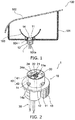
- FIG. 1 is a schematic partial sectional view illustrating a vehicle lighting device 1 and the vehicle lamp 100 according to the embodiment.
- the vehicle lighting device 1 As illustrated in FIG. 1 , the vehicle lighting device 1, a housing 101, a cover 102, an optical element portion 103, and a seal member 104 are provided in the vehicle lamp 100.
- the housing 101 has a box shape of which one end portion is opened.
- the housing 101 can be formed of, for example, resin and the like through which light is not transmitted.
- a mounting hole 101a into which a storage portion 11 of the vehicle lighting device 1 is inserted is provided in a bottom surface of the housing 101.
- Concave portions, into which convex portions 14 provided in the storage portion 11 are inserted, are provided in a periphery of the mounting hole 101a.
- a case where the mounting hole 101a is directly provided in the housing 101 is exemplified, but a mounting member having the mounting hole 101a may be provided in the housing 101.
- the storage portion 11 having the convex portions 14 is inserted into the mounting hole 101a and the vehicle lighting device 1 is rotated. Then, the convex portions 14 are held by the concave portions provided on the periphery of the mounting hole 101a.
- Such a mounting method is called a twist-lock.
- the cover 102 is provided so as to close an opening of the housing 101.
- the cover 102 can be formed of resin and the like having a light-transmitting property.
- the cover 102 can have functions of a lens and the like.
- the optical element portion 103 performs reflection, diffusion, guiding, and condensing of the light emitted from the vehicle lighting device 1, formation of a predetermined light distribution pattern, and the like.
- the optical element portion 103 illustrated in FIG. 1 is a reflector, reflects the light emitted from the vehicle lighting device 1, and causes the predetermined light distribution pattern to be formed.
- the optical element portion 103 is the reflector, the optical element portion 103 is on the inside of the housing 101 and can be provided coaxially with a central axis of the mounting hole 101a.
- the seal member 104 is provided between a flange portion 12 and the housing 101.
- the seal member 104 can be formed of a material having elasticity such as rubber or silicone resin.
- the seal member 104 When mounting the vehicle lighting device 1 on the vehicle lamp 100, the seal member 104 is interposed between the flange portion 12 and the housing 101. Thus, an interior space of the housing 101 is closed by the seal member 104.
- the convex portions 14 are pressed against the housing 101 by elastic force of the seal member 104.
- the vehicle lighting device 1 can be suppressed to be separated from the housing 101.
- FIG. 2 is a schematic perspective view illustrating the vehicle lighting device 1.
- FIG. 3 is a schematic perspective view illustrating a light emitting module 20.
- a body portion 10 As illustrated in FIG. 2 , a body portion 10, a light emitting module 20, a socket 30, and a power supply portion 40 are provided in the vehicle lighting device 1.
- the storage portion 11, the flange portion 12, fins 13, and the convex portions 14 are provided in the body portion 10.
- An appearance of the storage portion 11 has a cylindrical shape and the storage portion 11 protrudes from one surface of the flange portion 12.
- a concave portion 11a is provided in an end portion of the storage portion 11 on a side opposite to the flange portion 12 side.
- a substrate 21 is provided on a bottom surface of the concave portion 11a.
- a surface of the substrate 21 on a side opposite to a side on which a light emitting portion 22 is provided comes into contact with the bottom surface of the concave portion 11a.
- the light emitting module 20 is provided in the end portion of the storage portion 11 on a side opposite to a flange portion 12 side.
- a plurality of power supply terminals 41 protrude from the bottom surface of the concave portion 11a.
- the plurality of the power supply terminals 41 do not come into contact with the bottom surface of the concave portion 11a.
- the flange portion 12 has a disc shape, the storage portion 11 is provided on one surface, and the fins 13 are provided on the other surface.
- a plurality of the fins 13 are provided to protrude from the surface of the flange portion 12.
- the plurality of the fins 13 have a plate shape and function as radiating fins.
- the convex portion 14 is provided in a side wall of the storage portion 11.
- the convex portion 14 protrudes outward from the side wall of the storage portion 11.
- the number and arrangement position of the convex portions 14 are not specifically limited.
- convex portions 14 are provided. In the case of FIG. 2 , four convex portions 14 are provided.
- the body portion 10 has a function of storing the light emitting module 20 and a function of radiating heat generated in the light emitting module 20 to the outside of the vehicle lighting device 1.
- the body portion 10 is formed of a material having high thermal conductivity in consideration of releasing heat to the outside.
- the body portion 10 can be formed, for example, of metal such as aluminum or resin having high thermal conductivity.
- the resin having high thermal conductivity is obtained by mixing, for example, fibers or particles made of carbon having high thermal conductivity and the like with resin such as polyethylene terephthalate (PET) or nylon.
- resin such as polyethylene terephthalate (PET) or nylon.
- the vehicle lighting device 1 is made to be light-weight.
- the body portion 10 is formed of resin having high thermal conductivity.
- the storage portion 11, the flange portion 12, the fins 13, and the convex portions 14 can be integrally formed.
- the storage portion 11, the flange portion 12, the fins 13, and the convex portions 14 are separately formed, and can be bonded together. If the storage portion 11, the flange portion 12, the fins 13, and the convex portions 14 are separately formed, these members can be formed of the same material or can be formed of different materials.
- the substrate 21, a wiring pattern 24, the light emitting portion 22, a control portion 23, a frame portion 26, a diffusion portion 27, and a bonding portion 28 are provided in the light emitting module 20.
- the substrate 21 has a plate shape and the wiring pattern 24 is provided on a surface thereof.
- a material or a structure of the substrate 21 is not specifically limited.
- the substrate 21 can be formed of an inorganic material (ceramics) such as aluminum oxide or aluminum nitride, an organic material such as paper phenol or glass epoxy, and the like.
- the substrate 21 can be formed by coating a surface of a metal plate with an insulating material.
- the insulating material may be formed of an organic material or may be formed of an inorganic material.
- the substrate 21 is formed by using a material having high thermal conductivity in terms of heat radiation.
- a material having high thermal conductivity ceramics such as aluminum oxide or aluminum nitride, a material that is obtained by coating a surface of a metal plate with an insulating material, and the like can be exemplified.
- the substrate 21 may be a single layer or may be a multi-layer.
- the wiring pattern 24 is provided on at least one surface of the substrate 21.
- the wiring pattern 24 can be provided on both surfaces of the substrate 21, but in order to reduce manufacturing costs, it is preferable that the wiring pattern 24 is provided on one surface of the substrate 21.
- An input terminal 24a is provided in the wiring pattern 24.
- a plurality of the input terminals 24a are provided.
- the power supply terminal 41 is electrically connected to the input terminal 24a.
- the light emitting portion 22 is mounted on the wiring pattern 24 provided on the surface of the substrate 21 using a Chip on Board (COB) method.
- COB Chip on Board
- the light emitting portion 22 is electrically connected to the power supply terminal 41 via the wiring pattern 24.
- the light emitting portion 22 can have electrodes (not illustrated) on a surface (upper surface) on a side opposite to a side on which the wiring pattern 24 is provided.
- the electrodes (not illustrated) may be provided on a surface (lower surface) on the side on which the wiring pattern 24 is provided and the surface (upper surface) on the side opposite to the side on which the wiring pattern 24 is provided, or may be provided only on either side.
- the electrodes (not illustrated) provided on the lower surface of the light emitting portion 22 are electrically connected to a mounting pad provided in the wiring pattern 24 via a conductive thermoset material such as silver paste.
- the electrodes (not illustrated) provided on the upper surface of the light emitting portion 22 are electrically connected to a wiring pad provided in the wiring pattern 24 via wiring.
- the light emitting portion 22 can have a first light emitting portion 22a that emits, for example, light of a first color and a second light emitting portion 22b that emits light of a second color different from the first color.
- FIG. 4 is a schematic perspective view illustrating the light emitting portion 22.
- the first light emitting portion 22a has a light emitting element 22c and a phosphor portion 22da (corresponding to an example of a first phosphor portion) that is provided on a light emitting surface of the light emitting element 22c.
- the second light emitting portion 22b has a light emitting element 22c and a phosphor portion 22db (corresponding to an example of a second phosphor portion) that is provided on a light emitting surface of the light emitting element 22c.
- the light emitting element 22c can be, for example, a light emitting diode, an organic light emitting diode, a laser diode, and the like.
- the phosphor portions 22da and 22db include phosphor (corresponding to an example of a first phosphor or a second phosphor) that is excited by light emitted from the light emitting elements 22c and emits fluorescence.
- the phosphor portions 22da and 22db can be, for example, a tape including phosphor.
- the tape-shaped phosphor portions 22da and 22db are bonded to the light emitting surface of the light emitting element 22c.
- the color of the light can be controlled by a type of the phosphor, and a content of the phosphor included in the phosphor portions 22da and 22db.
- the light emitting element 22c is a blue light emitting diode and the phosphor portion 22da can include phosphor emitting yellow fluorescence.
- the white light is emitted from the first light emitting portion 22a by mixing the blue light emitted from the light emitting element 22c and the yellow light emitted from the phosphor.
- a ratio of the blue light and the yellow light can be controlled by an amount of the phosphor.
- the light emitting element 22c is the blue light emitting diode and the phosphor portion 22db can include phosphor emitting red fluorescence or can include phosphor emitting red fluorescence, phosphor emitting yellow fluorescence, and the like.
- a light emitting diode emitting the red light a light emitting diode emitting the yellow green light, a light emitting diode emitting the blue light, a light emitting diode emitting green light, and the like as it is.
- types of the color of the light are not limited to two types.
- the types of the color of the light may be two types or more.
- the type or the number of the color of the light can be appropriately changed depending on usage of the vehicle lighting device 1 and the like.
- the white light is used for a daytime running lamp, a position lamp, a back lamp, and the like.
- the red light is used for a stop lamp, a tail lamp, and the like.
- the amber light is used for a turn signal lamp and the like.
- the yellow light is used for a fog lamp and the like.
- the number, a size, and arrangement of the light emitting portions 22, and the like are not limited to the example and can be appropriately changed depending on the size and the usage of the vehicle lighting device 1, and the like.
- the control portion 23 is mounted on the wiring pattern 24.
- the control portion 23 causes one of the first light emitting portion 22a and the second light emitting portion 22b to emit light. In this case, if light is emitted from the first light emitting portion 22a, the control portion 23 causes the second light emitting portion 22b not to emit light. If light is emitted from the second light emitting portion 22b, the control portion 23 causes the first light emitting portion 22a not to emit light.
- control portion 23 controls brightness of light emitted from the first light emitting portion 22a and the second light emitting portion 22b respectively.
- the first light emitting portion 22a emits the white light
- the control portion 23 controls light flux of the light emitted from the first light emitting portion 22a to be approximately 300 lumens.
- the control portion 23 controls the light flux of the light emitted from the first light emitting portion 22a to be approximately 50 lumens.
- the second light emitting portion 22b can be used as the stop lamp or the tail lamp. If the second light emitting portion 22b is used as the stop lamp, the control portion 23 controls the light flux of the light emitted from the second light emitting portion 22b to be approximately 100 lumens. If the second light emitting portion 22b is used as the tail lamp, the control portion 23 controls the light flux of the light emitted from the second light emitting portion 22b to be approximately 10 lumens.
- the number of switching of the brightness or a degree of the brightness is not limited to the example.
- a film-like resistor for controlling a value of a current flowing through the light emitting element 22c such that the brightness of the light emitted from the light emitting element 22c is within a predetermined range. It is possible to provide a diode (not illustrated) such that a reverse voltage is not applied to the light emitting element 22c and pulse noise from a reverse direction is not applied to the light emitting element 22c.
- the frame portion 26 is provided on the substrate 21 so as to surround the first light emitting portion 22a and the second light emitting portion 22b.
- the frame portion 26 has, for example, an annular shape and the first light emitting portion 22a and the second light emitting portion 22b are disposed in a center portion 26a.
- the frame portion 26 can be formed of, for example, resin such as polybutylene terephthalate (PBT) or polycarbonate (PC), ceramics, or the like.
- resin such as polybutylene terephthalate (PBT) or polycarbonate (PC), ceramics, or the like.
- the material of the frame portion 26 is resin, it is possible to improve reflectivity with respect to the light emitted from the first light emitting portion 22a and the second light emitting portion 22b by mixing particles consisting of titanium oxide and the like with the resin.
- the particles are not limited to the particles of titanium oxide and particles consisting of a material having high reflectivity with respect to the light emitted from the first light emitting portion 22a and the second light emitting portion 22b may be mixed.
- the frame portion 26 can be formed of, for example, white resin.
- a side wall surface 26b on the center portion 26a side of the frame portion 26 has an inclined surface. Some of the light emitted from the first light emitting portion 22a and the second light emitting portion 22b is reflected on the side wall surface 26b of the frame portion 26 and is emitted toward a front side of the vehicle lighting device 1.
- light which is some of the light emitted from the first light emitting portion 22a and the second light emitting portion 22b toward the front side of the vehicle lighting device 1 and is total reflected on an upper surface (interface between the diffusion portion 27 and outside air) of the diffusion portion 27, is reflected on the side wall surface 26b on the center portion 26a side of the frame portion 26 and is emitted again toward the front side of the vehicle lighting device 1.
- the frame portion 26 can also have a function of a reflector. Moreover, a form of the frame portion 26 is not limited to the example and can be appropriately changed.
- the diffusion portion 27 is provided in the center portion 26a of the frame portion 26.
- the diffusion portion 27 is provided to cover the inside of the frame portion 26. That is, the diffusion portion 27 is provided on the inside of the frame portion 26 and covers the first light emitting portion 22a and the second light emitting portion 22b.
- the diffusion portion 27 has the light-transmitting property.
- the diffusion portion 27 is formed of a material having the light-transmitting property.
- the diffusion portion 27 can be formed of, for example, silicone resin and the like.
- the diffusion portion 27 can be formed by, for example, filling the center portion 26a of the frame portion 26 with resin. Filling with resin can be performed by using a liquid dispensing device such as a dispenser.
- the diffusion portion 27 can further include a diffusion material that diffuses the light emitted from the first light emitting portion 22a and the second light emitting portion 22b.
- the diffusion material can be, for example, particles and fibers made of titanium oxide, and the like.
- the light emitted from the first light emitting portion 22a is mainly applied to the front side of the first light emitting portion 22a.
- the light emitted from the second light emitting portion 22b is mainly applied to the front side of the second light emitting portion 22b.
- the first light emitting portion 22a and the second light emitting portion 22b are provided in a position which is shifted from the central axis of the vehicle lighting device 1.
- the light of the first color emitted from the first light emitting portion 22a and the light of the second color emitted from the second light emitting portion 22b are respectively applied to the positions which are shifted from the central axis of the vehicle lighting device 1 and are different from each other.
- the diffusion portion 27 covering both the first light emitting portion 22a and the second light emitting portion 22b is provided, for both the light emitted from the first light emitting portion 22a and the light emitted from the second light emitting portion 22b, similar diffusion is generated on the inside of the diffusion portion 27.
- both the light emitted from the first light emitting portion 22a and the light emitted from the second light emitting portion 22b can be substantially uniformly emitted from the surface of the diffusion portion 27.
- the diffusion portion 27 covers the first light emitting portion 22a, the second light emitting portion 22b, the wiring pattern 24 disposed in the center portion 26a of the frame portion 26, and the like.
- the bonding portion 28 bonds the frame portion 26 and the substrate 21.
- the bonding portion 28 has a film-like member and is provided between the frame portion 26 and the substrate 21.
- the bonding portion 28 can be formed, for example, by curing silicone-based adhesive or epoxy-based adhesive.
- FIG. 5 is a schematic perspective view illustrating the socket 30.
- a body portion 30a, a female terminal 30b, and wiring 30c are provided in the socket 30.
- the body portion 30a is formed of an insulating material such as resin.
- a protrusion portion 30a1 is provided on a side wall of the body portion 30a.
- the socket 30 is held on the body portion 10 by fitting the protrusion portion 30a1 into a concave portion provided in the body portion 10.
- the female terminal 30b extends on the inside of the body portion 30a.
- One end portion of the female terminal 30b is exposed on one end surface of the body portion 30a.
- the power supply terminal 41 is fitted into the end portion of the female terminal 30b exposed on one end surface of the body portion 30a.
- the wiring 30c is electrically connected to the other end portion of the female terminal 30b.
- a power supply (not illustrated) and the like are electrically connected to the wiring 30c.
- the power supply (not illustrated) and the like are electrically connected to the light emitting portion 22 by fitting the socket 30 into the power supply terminal 41.
- the socket 30 can be bonded to an element on a body portion 10 side, for example, by using adhesive and the like.
- the power supply terminal 41 and a holding portion 42 are provided in the power supply portion 40.
- a plurality of the power supply terminals 41 are provided.
- the power supply terminal 41 has a wire-like member and is formed of a conductive material such as metal.
- the plurality of the power supply terminals 41 extend by passing through the holding portion 42.
- the power supply terminal 41 protruding from the other end portion of the holding portion 42 is fitted into the female terminal 30b.
- two power supply terminals 41 are exemplified, but the number and a shape of the power supply terminals 41, and the like are not limited to the example, and can be appropriately changed.
- the body portion 10 is formed of resin having high thermal conductivity, metal, and the like.
- the resin having high thermal conductivity is obtained by mixing a material having conductivity such as carbon with resin.
- the resin having high thermal conductivity has conductivity.
- the holding portion 42 which is formed of a material having an insulating property, is provided between the body portion 10 and the power supply terminal 41.
- the holding portion 42 is provided on the inside of a hole provided in the body portion 10.
- a temperature of an environment of use is -40°C to 85°C.
- a linear expansion coefficient of resin having high thermal conductivity that is a material of the body portion 10 and a linear expansion coefficient of resin that is a material of the holding portion 42 become a value as close as possible.
- the resin having high thermal conductivity obtained by mixing fibers or particles formed of carbon into PET it is possible to form the holding portion 42 by using PET.
- FIG. 6 is a schematic perspective view illustrating the light emitting module 120 according to another embodiment.
- the light emitting portion 22 is mounted on the wiring pattern 24 using the COB method.
- a plastic leaded chip carrier (PLCC) type light emitting portion 122 is mounted on a wiring pattern 24.
- a substrate 21, the wiring pattern 24, the light emitting portion 122, a control portion 23, and a sealing portion 127 are provided in the light emitting module 120.
- the light emitting portion 122 has the first light emitting portion 22a that emits the light of the first color and the second light emitting portion 22b that emits the light of the second color different from the first color described above.
- the first light emitting portion 22a is provided on an inside of a concave portion 122b provided in an envelope 122a (corresponding to an example of the first envelope).
- the first light emitting portion 22a is electrically connected to a lead 122c exposed on the inside of the concave portion 122b.
- the second light emitting portion 22b is provided on the inside of the concave portion 122b provided in the envelope 122a (corresponding to an example of the second envelope).
- the second light emitting portion 22b is electrically connected to the lead 122c exposed on the inside of the concave portion 122b.
- the envelope 122a can be formed of, for example, resin such as PBT or PC, ceramic, and the like.
- a material of the envelope 122a is resin, it is possible to improve reflectivity with respect to the light emitted from the first light emitting portion 22a and the second light emitting portion 22b by mixing particles such as titanium oxide with the resin.
- the particles of titanium oxide and particles which are formed of a material having high reflectivity with respect to the light emitted from the first light emitting portion 22a and the second light emitting portion 22b, may be mixed with the resin.
- the envelope 122a can be formed of, for example, white resin.
- a side wall of the concave portion 122b of the envelope 122a is an inclined surface. Some of the light emitted from the first light emitting portion 22a and the second light emitting portion 22b is reflected on the side wall of the concave portion 122b and is emitted toward a front side of the vehicle lighting device 1.
- light which is some of the light emitted from the first light emitting portion 22a and the second light emitting portion 22b toward the front side of the vehicle lighting device 1 and is totally reflected on an upper surface (interface between the sealing portion 127 and outside air) of the sealing portion 127, is reflected on the side wall of the concave portion 122b and is emitted again toward the front side of the vehicle lighting device 1.
- the envelope 122a can also have a function of a reflector. Moreover, a form of the envelope 122a is not limited to the example and can be appropriately changed.
- One end portion of the lead 122c is exposed on the inside of the concave portion 122b.
- the other end portion of the lead 122c is bent toward a surface (lower surface) on a side opposite to a side on which the concave portion 122b of the envelope 122a is opened.
- the lead 122c can be, for example, a J-bend type lead.
- the first light emitting portion 22a and the second light emitting portion 22b are electrically connected to the wiring pattern 24 via the lead 122c.
- the sealing portion 127 is provided on the inside of the concave portion 122b of the envelope 122a.
- the sealing portion 127 is provided to cover the inside of the concave portion 122b. That is, the sealing portion 127 is provided on the inside of the concave portion 122b and covers the first light emitting portion 22a, the second light emitting portion 22b, and one end portion of the lead 122c.
- the sealing portion 127 is formed of a material having the light-transmitting property.
- the sealing portion 127 can be formed of, for example, silicone resin and the like.
- the sealing portion 127 can be formed by, for example, filling the concave portion 122b of the envelope 122a with resin. Filling with resin can be performed by using a liquid dispensing device such as a dispenser.
- the concave portion 122b of the envelope 122a is filled with resin, it is possible to suppress mechanical contact of the first light emitting portion 22a, the second light emitting portion 22b, and the like from the outside. In addition, it is possible to suppress that gas, moisture, and the like are adhered to the first light emitting portion 22a, the second light emitting portion 22b, and the like. Thus, it is possible to improve reliability with respect to the vehicle lighting device 1.
- the light emitting element 22c is provided on the inside of the concave portion 122b of the envelope 122a in place of the first light emitting portion 22a and the phosphor included in the phosphor portion 22da can be included in the sealing portion 127.
- the light emitting element 22c is provided on the inside of the concave portion 122b of the envelope 122a in place of the second light emitting portion 22b and the phosphor included in the phosphor portion 22db can be included in the sealing portion 127.
- the sealing portion 127 covers one of the first light emitting portion 22a and the second light emitting portion 22b.
- the light emitted from the first light emitting portion 22a and the second light emitting portion 22b is not introduced into the inside of one sealing portion 127 different from the diffusion portion 27 described above.
- the light emitted from the first light emitting portion 22a is mainly applied to the front side of the first light emitting portion 22a via the sealing portion 127.
- the light emitted from the second light emitting portion 22b is mainly applied to the front side of the second light emitting portion 22b via the sealing portion 127.
- the light of the first color emitted from the first light emitting portion 22a and the light of the second color emitted from the second light emitting portion 22b are respectively applied to the positions which are shifted from the central axis of the vehicle lighting device 1 and are different from each other.
- first light emitting portion 22a and the second light emitting portion 22b are provided on the inside of the envelope 122a. Thus, it is possible to suppress that heat generated by one of the first light emitting portion 22a and the second light emitting portion 22b is transmitted to the other side.
- the first light emitting portion 22a and the second light emitting portion 22b are provided in a region of which a diameter is equal to or less than 20 mm, and particularly preferably in a region of which a diameter is equal to or less than 10 mm, it is possible to suppress that the light distribution characteristics of the vehicle lighting device 1 are changed for each color.
- the first light emitting portion 22a and the second light emitting portion 22b are provided in the region of which the diameter is equal to or less than 20 mm, and particularly preferably in the region of which the diameter is equal to or less than 10 mm.
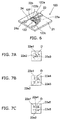
- FIGs. 7A to 7C are schematic views illustrating arrangements of the light emitting portion.
- Light emitting portions 22e1 to 22e5 can respectively emit different colors and a part of the light emitting portions 22e1 to 22e5 can emit light of the same color.
- the number and arrangement shape of the light emitting portions are not particularly limited and it is preferable that the light emitting portions are provided in a region of which a diameter D is equal to or less than 20 mm, and particularly preferably in a region of which a diameter D is equal to or less than 10 mm.
- all the light emitting portions are provided in the region of which the diameter D is equal to or less than 20 mm and particularly preferably in the region of which the diameter D is equal to or less than 10 mm, it is possible to suppress that the light distribution characteristics of the vehicle lighting device 1 are changed for each color.
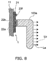
- FIG. 8 is a schematic sectional view illustrating an optical element portion 103a according to another embodiment.
- the optical element portion performs reflection, diffusion, guiding, and condensing of the light emitted from the vehicle lighting device 1, formation of a predetermined light distribution pattern, and the like.
- the optical element portion 103 illustrated in FIG. 1 is the reflector and the predetermined light distribution pattern is formed by reflecting the light emitted from the vehicle lighting device 1.
- the optical element portion 103a illustrated in FIG. 8 is a light guide body (light guide), guides the light emitted from the vehicle lighting device 1, and applies the guided light to a desired position or region.
- the optical element portion 103a is formed of a material having the light-transmitting property such as transparent resin or glass.
- Light La emitted from the light emitting portion 22a propagates through the inside of the optical element portion 103a and is applied from a predetermined region of the optical element portion 103a.
- Light Lb emitted from the light emitting portion 22b propagates through the inside of the optical element portion 103a and is applied from a predetermined region of the optical element portion 103a.
- the optical element portion 103a is the light guide body, the optical element portion 103a has the same diffusion operation as the diffusion portion 27 described above. Thus, if the optical element portion 103a is the light guide body, the diffusion portion 27 is not necessarily required.
- optical element portion can be provided in at least one of a plurality of the light emitting portions.
- the optical element portion 103a is provided in the light emitting portions 22a and 22b, and the optical element portion 103a cannot be provided in a light emitting portion 22f.
- a plurality of the optical element portions having different functions are provided or a plurality of the optical element portions having the same function may be provided.
Landscapes
- Engineering & Computer Science (AREA)
- General Engineering & Computer Science (AREA)
- Mechanical Engineering (AREA)
- Physics & Mathematics (AREA)
- Microelectronics & Electronic Packaging (AREA)
- Optics & Photonics (AREA)
- Led Device Packages (AREA)
- Non-Portable Lighting Devices Or Systems Thereof (AREA)
- Fastening Of Light Sources Or Lamp Holders (AREA)
- Arrangement Of Elements, Cooling, Sealing, Or The Like Of Lighting Devices (AREA)
- Planar Illumination Modules (AREA)
Abstract
Description
- Embodiments described herein relate generally to a vehicle lighting device and a vehicle lamp.
- Recently, a vehicle lighting device (for example, a lighting device for automobiles) using a light emitting diode (LED) as a light source has been implemented in place of an incandescent bulb (filament bulb).
- In general, the vehicle lighting device emits light of a different color for each function. For example, a vehicle lighting device used for a position lamp emits white light. A vehicle lighting device used for a brake lamp emits red light.
- Therefore, a vehicle lighting device including light emitting diodes emitting red light, light emitting diodes emitting yellow light, and light emitting diodes emitting white light, or a vehicle lighting device including light emitting diodes emitting white light and light emitting diodes emitting blue light, which selectively emits light of one of the colors has been proposed.
- In this case, the light is emitted from different positions depending on a desired color. For example, the red light is emitted from the light emitting diodes emitting the red light. The white light is emitted from the light emitting diodes emitting the white light.
- Therefore, there is a concern that light distribution characteristics of the vehicle lighting device are changed for each color of the light.
- Thus, development of a vehicle lighting device and a vehicle lamp, which can selectively emit light of a plurality of colors and can suppress a change in light distribution characteristics, has been desired.
-
-
FIG. 1 is a schematic partial sectional view illustrating a vehicle lighting device and a vehicle lamp according to an embodiment. -
FIG. 2 is a schematic perspective view illustrating the vehicle lighting device. -
FIG. 3 is a schematic perspective view illustrating a light emitting module. -
FIG. 4 is a schematic perspective view illustrating a light emitting portion. -
FIG. 5 is a schematic perspective view illustrating a socket. -
FIG. 6 is a schematic perspective view illustrating a light emitting module according to another embodiment. -
FIGs. 7A to 7C are schematic views illustrating arrangements of the light emitting portion. -
FIG. 8 is a schematic sectional view illustrating an optical element portion according to another embodiment. - A vehicle lighting device according to an exemplary embodiment includes a flange portion; a storage portion that protrudes from one surface of the flange portion; and a light emitting module that is provided in an end portion of the storage portion on a side opposite to the flange portion side.
- The light emitting module includes a substrate, a first light emitting portion that is provided in the substrate, has a light emitting element, and emits white light, a second light emitting portion that is provided in the substrate, has a light emitting element, and emits red or amber light, a control portion that causes one of the first light emitting portion and the second light emitting portion to emit light, and a diffusion portion that has a light-transmitting property and covers the first light emitting portion and the second light emitting portion.
- In the vehicle lighting device, it is possible to selectively emit light of a plurality of colors and to suppress a change in light distribution characteristics.
- Furthermore, the first light emitting portion and the second light emitting portion may be provided in a region of which a diameter is within 20 mm on the substrate.
- In this case, it is possible to further suppress the change in the light distribution characteristics.
- A vehicle lighting device according to another exemplary embodiment includes a flange portion; a storage portion that protrudes from one surface of the flange portion; and a light emitting module that is provided in an end portion of the storage portion on a side opposite to the flange portion side.
- The light emitting module includes a substrate, a first light emitting portion that has a light emitting element and emits white light, a second light emitting portion that has a light emitting element and emits red or amber light, a control portion that causes one of the first light emitting portion and the second light emitting portion to emit light, a first envelope that stores the first light emitting portion and is provided in the substrate, and a second envelope that stores the second light emitting portion and is provided in the substrate. The first light emitting portion and the second light emitting portion are provided in a region of which a diameter is within 20 mm on the substrate.
- In the vehicle lighting device, it is possible to selectively emit light of a plurality of colors and to suppress a change in light distribution characteristics.
- Furthermore, the first light emitting portion may have a first phosphor portion including a first phosphor, and the second light emitting portion may have a second phosphor portion including a second phosphor.
- In this case, it is possible to easily generate light of a plurality of colors.
- Furthermore, the control portion may further control brightness of light emitted from at least one of the first light emitting portion and the second light emitting portion.
- In this case, it is possible to achieve expansion of applications.
- A vehicle lamp according to still another exemplary embodiment includes the above-described vehicle lighting device; and an optical element portion on which light emitted from the vehicle lighting device is incident.
- According to the vehicle lamp, it is possible to selectively emit light of a plurality of colors and to suppress a change in light distribution characteristics.
- Furthermore, the optical element portion may be a light guide body.
- In this case, it is possible to achieve expansion of applications.
- Hereinafter, exemplary embodiments will be described with reference to the drawings. Moreover, the same reference numerals are given to the same configuration elements in each drawing and detailed description will be appropriately omitted.
- As a
vehicle lamp 100 of the exemplary embodiment, for example, a front combination light (formed by appropriately combining, for example, a daytime running lamp (DRL; Daylight Running Lamp), a position lamp, a turn signal lamp, and the like), a rear combination light (formed by appropriately combining, for example, a stop lamp, a tail lamp, a turn signal lamp, a back lamp, a fog lamp, and the like), and the like can be exemplified. - Moreover, hereinafter, as an example, a case where the automobile includes the front combination light in which the
vehicle lamp 100 is provided in the automobile will be described. However, thevehicle lamp 100 is not limited to the front combination light provided in the automobile. Thevehicle lamp 100 is provided in the automobile, a railway vehicle, and the like, and may selectively emit light of a plurality of colors. -
FIG. 1 is a schematic partial sectional view illustrating avehicle lighting device 1 and thevehicle lamp 100 according to the embodiment. - As illustrated in
FIG. 1 , thevehicle lighting device 1, ahousing 101, acover 102, anoptical element portion 103, and aseal member 104 are provided in thevehicle lamp 100. - The
housing 101 has a box shape of which one end portion is opened. Thehousing 101 can be formed of, for example, resin and the like through which light is not transmitted. - A
mounting hole 101a into which astorage portion 11 of thevehicle lighting device 1 is inserted is provided in a bottom surface of thehousing 101. - Concave portions, into which convex
portions 14 provided in thestorage portion 11 are inserted, are provided in a periphery of themounting hole 101a. - Moreover, a case where the
mounting hole 101a is directly provided in thehousing 101 is exemplified, but a mounting member having themounting hole 101a may be provided in thehousing 101. - When mounting the
vehicle lighting device 1 on thevehicle lamp 100, thestorage portion 11 having theconvex portions 14 is inserted into themounting hole 101a and thevehicle lighting device 1 is rotated. Then, theconvex portions 14 are held by the concave portions provided on the periphery of themounting hole 101a. - Such a mounting method is called a twist-lock.
- The
cover 102 is provided so as to close an opening of thehousing 101. Thecover 102 can be formed of resin and the like having a light-transmitting property. - The
cover 102 can have functions of a lens and the like. - Light emitted from the
vehicle lighting device 1 is incident on theoptical element portion 103. - The
optical element portion 103 performs reflection, diffusion, guiding, and condensing of the light emitted from thevehicle lighting device 1, formation of a predetermined light distribution pattern, and the like. - For example, the
optical element portion 103 illustrated inFIG. 1 is a reflector, reflects the light emitted from thevehicle lighting device 1, and causes the predetermined light distribution pattern to be formed. - If the
optical element portion 103 is the reflector, theoptical element portion 103 is on the inside of thehousing 101 and can be provided coaxially with a central axis of themounting hole 101a. - The
seal member 104 is provided between aflange portion 12 and thehousing 101. - The
seal member 104 can be formed of a material having elasticity such as rubber or silicone resin. - When mounting the
vehicle lighting device 1 on thevehicle lamp 100, theseal member 104 is interposed between theflange portion 12 and thehousing 101. Thus, an interior space of thehousing 101 is closed by theseal member 104. - In addition, the
convex portions 14 are pressed against thehousing 101 by elastic force of theseal member 104. Thus, thevehicle lighting device 1 can be suppressed to be separated from thehousing 101. -
FIG. 2 is a schematic perspective view illustrating thevehicle lighting device 1. -
FIG. 3 is a schematic perspective view illustrating alight emitting module 20. - As illustrated in
FIG. 2 , abody portion 10, alight emitting module 20, asocket 30, and apower supply portion 40 are provided in thevehicle lighting device 1. - As illustrated in
FIG. 2 , thestorage portion 11, theflange portion 12,fins 13, and theconvex portions 14 are provided in thebody portion 10. - An appearance of the
storage portion 11 has a cylindrical shape and thestorage portion 11 protrudes from one surface of theflange portion 12. Aconcave portion 11a is provided in an end portion of thestorage portion 11 on a side opposite to theflange portion 12 side. - A
substrate 21 is provided on a bottom surface of theconcave portion 11a. A surface of thesubstrate 21 on a side opposite to a side on which alight emitting portion 22 is provided comes into contact with the bottom surface of theconcave portion 11a. - That is, the
light emitting module 20 is provided in the end portion of thestorage portion 11 on a side opposite to aflange portion 12 side. - In addition, a plurality of
power supply terminals 41 protrude from the bottom surface of theconcave portion 11a. The plurality of thepower supply terminals 41 do not come into contact with the bottom surface of theconcave portion 11a. - The
flange portion 12 has a disc shape, thestorage portion 11 is provided on one surface, and thefins 13 are provided on the other surface. - A plurality of the
fins 13 are provided to protrude from the surface of theflange portion 12. The plurality of thefins 13 have a plate shape and function as radiating fins. - The
convex portion 14 is provided in a side wall of thestorage portion 11. Theconvex portion 14 protrudes outward from the side wall of thestorage portion 11. - The number and arrangement position of the
convex portions 14 are not specifically limited. - In this case, if the plurality of the
convex portions 14 are provided, it is possible to stabilize holding of thevehicle lighting device 1. - In order to stabilize holding of the
vehicle lighting device 1, it is preferable that three or moreconvex portions 14 are provided. In the case ofFIG. 2 , fourconvex portions 14 are provided. - Here, the
body portion 10 has a function of storing thelight emitting module 20 and a function of radiating heat generated in thelight emitting module 20 to the outside of thevehicle lighting device 1. - Therefore, it is preferable that the
body portion 10 is formed of a material having high thermal conductivity in consideration of releasing heat to the outside. - The
body portion 10 can be formed, for example, of metal such as aluminum or resin having high thermal conductivity. - The resin having high thermal conductivity is obtained by mixing, for example, fibers or particles made of carbon having high thermal conductivity and the like with resin such as polyethylene terephthalate (PET) or nylon.
- It is preferable that the
vehicle lighting device 1 is made to be light-weight. - Therefore, it is preferable that the
body portion 10 is formed of resin having high thermal conductivity. - In addition, the
storage portion 11, theflange portion 12, thefins 13, and theconvex portions 14 can be integrally formed. - Moreover, the
storage portion 11, theflange portion 12, thefins 13, and theconvex portions 14 are separately formed, and can be bonded together. If thestorage portion 11, theflange portion 12, thefins 13, and theconvex portions 14 are separately formed, these members can be formed of the same material or can be formed of different materials. - As illustrated in
FIG. 3 , thesubstrate 21, awiring pattern 24, thelight emitting portion 22, acontrol portion 23, aframe portion 26, adiffusion portion 27, and abonding portion 28 are provided in thelight emitting module 20. - The
substrate 21 has a plate shape and thewiring pattern 24 is provided on a surface thereof. - A material or a structure of the
substrate 21 is not specifically limited. For example, thesubstrate 21 can be formed of an inorganic material (ceramics) such as aluminum oxide or aluminum nitride, an organic material such as paper phenol or glass epoxy, and the like. In addition, thesubstrate 21 can be formed by coating a surface of a metal plate with an insulating material. Moreover, in a case of coating the surface of the metal plate with the insulating material, the insulating material may be formed of an organic material or may be formed of an inorganic material. - If a heating value of the
light emitting portion 22 is large, it is preferable that thesubstrate 21 is formed by using a material having high thermal conductivity in terms of heat radiation. As the material having high thermal conductivity, ceramics such as aluminum oxide or aluminum nitride, a material that is obtained by coating a surface of a metal plate with an insulating material, and the like can be exemplified. - In addition, the
substrate 21 may be a single layer or may be a multi-layer. - The
wiring pattern 24 is provided on at least one surface of thesubstrate 21. - The
wiring pattern 24 can be provided on both surfaces of thesubstrate 21, but in order to reduce manufacturing costs, it is preferable that thewiring pattern 24 is provided on one surface of thesubstrate 21. - An
input terminal 24a is provided in thewiring pattern 24. - A plurality of the
input terminals 24a are provided. Thepower supply terminal 41 is electrically connected to theinput terminal 24a. - The
light emitting portion 22 is mounted on thewiring pattern 24 provided on the surface of thesubstrate 21 using a Chip on Board (COB) method. - Therefore, the
light emitting portion 22 is electrically connected to thepower supply terminal 41 via thewiring pattern 24. - The
light emitting portion 22 can have electrodes (not illustrated) on a surface (upper surface) on a side opposite to a side on which thewiring pattern 24 is provided. The electrodes (not illustrated) may be provided on a surface (lower surface) on the side on which thewiring pattern 24 is provided and the surface (upper surface) on the side opposite to the side on which thewiring pattern 24 is provided, or may be provided only on either side. - The electrodes (not illustrated) provided on the lower surface of the
light emitting portion 22 are electrically connected to a mounting pad provided in thewiring pattern 24 via a conductive thermoset material such as silver paste. The electrodes (not illustrated) provided on the upper surface of thelight emitting portion 22 are electrically connected to a wiring pad provided in thewiring pattern 24 via wiring. - The
light emitting portion 22 can have a firstlight emitting portion 22a that emits, for example, light of a first color and a secondlight emitting portion 22b that emits light of a second color different from the first color. -
FIG. 4 is a schematic perspective view illustrating thelight emitting portion 22. - The first
light emitting portion 22a has alight emitting element 22c and a phosphor portion 22da (corresponding to an example of a first phosphor portion) that is provided on a light emitting surface of thelight emitting element 22c. - The second
light emitting portion 22b has alight emitting element 22c and a phosphor portion 22db (corresponding to an example of a second phosphor portion) that is provided on a light emitting surface of thelight emitting element 22c. - The
light emitting element 22c can be, for example, a light emitting diode, an organic light emitting diode, a laser diode, and the like. - The phosphor portions 22da and 22db include phosphor (corresponding to an example of a first phosphor or a second phosphor) that is excited by light emitted from the
light emitting elements 22c and emits fluorescence. - The phosphor portions 22da and 22db can be, for example, a tape including phosphor. In this case, the tape-shaped phosphor portions 22da and 22db are bonded to the light emitting surface of the
light emitting element 22c. - The color of the light can be controlled by a type of the phosphor, and a content of the phosphor included in the phosphor portions 22da and 22db.
- For example, if the first
light emitting portion 22a emits the white light, thelight emitting element 22c is a blue light emitting diode and the phosphor portion 22da can include phosphor emitting yellow fluorescence. - In this case, the white light is emitted from the first
light emitting portion 22a by mixing the blue light emitted from thelight emitting element 22c and the yellow light emitted from the phosphor. - Moreover, a ratio of the blue light and the yellow light can be controlled by an amount of the phosphor.
- For example, if most of the blue light emitted from the
light emitting element 22c is converted into the yellow light by increasing the amount of the phosphor emitting yellow fluorescence, it is possible to emit the yellow light from the firstlight emitting portion 22a. - For example, if the second
light emitting portion 22b emits red or amber light, thelight emitting element 22c is the blue light emitting diode and the phosphor portion 22db can include phosphor emitting red fluorescence or can include phosphor emitting red fluorescence, phosphor emitting yellow fluorescence, and the like. - In this case, it is possible to emit the red light or the amber light from the second
light emitting portion 22b by converting most of the blue light emitted from thelight emitting element 22c into the red light or the amber light. - Moreover, a case where the color of the light is changed by using the phosphor is exemplified, but it is possible to only use the
light emitting element 22c emitting a desired color. - For example, it is possible to use a light emitting diode emitting the red light, a light emitting diode emitting the yellow green light, a light emitting diode emitting the blue light, a light emitting diode emitting green light, and the like as it is.
- In addition, types of the color of the light are not limited to two types. The types of the color of the light may be two types or more. The type or the number of the color of the light can be appropriately changed depending on usage of the
vehicle lighting device 1 and the like. - For example, the white light is used for a daytime running lamp, a position lamp, a back lamp, and the like.
- The red light is used for a stop lamp, a tail lamp, and the like.
- The amber light is used for a turn signal lamp and the like.
- The yellow light is used for a fog lamp and the like.
- In addition, various colors of the light are used in lamps for decoration.
- In addition, the number, a size, and arrangement of the
light emitting portions 22, and the like are not limited to the example and can be appropriately changed depending on the size and the usage of thevehicle lighting device 1, and the like. - The
control portion 23 is mounted on thewiring pattern 24. - The
control portion 23 causes one of the firstlight emitting portion 22a and the secondlight emitting portion 22b to emit light. In this case, if light is emitted from the firstlight emitting portion 22a, thecontrol portion 23 causes the secondlight emitting portion 22b not to emit light. If light is emitted from the secondlight emitting portion 22b, thecontrol portion 23 causes the firstlight emitting portion 22a not to emit light. - In addition, the
control portion 23 controls brightness of light emitted from the firstlight emitting portion 22a and the secondlight emitting portion 22b respectively. - For example, if the first
light emitting portion 22a emits the white light, it is possible to use the firstlight emitting portion 22a as the daytime running lamp or the position lamp. If the firstlight emitting portion 22a is used as the daytime running lamp, thecontrol portion 23 controls light flux of the light emitted from the firstlight emitting portion 22a to be approximately 300 lumens. If the firstlight emitting portion 22a is used as the position lamp, thecontrol portion 23 controls the light flux of the light emitted from the firstlight emitting portion 22a to be approximately 50 lumens. - If the second
light emitting portion 22b emits the red light, the secondlight emitting portion 22b can be used as the stop lamp or the tail lamp. If the secondlight emitting portion 22b is used as the stop lamp, thecontrol portion 23 controls the light flux of the light emitted from the secondlight emitting portion 22b to be approximately 100 lumens. If the secondlight emitting portion 22b is used as the tail lamp, thecontrol portion 23 controls the light flux of the light emitted from the secondlight emitting portion 22b to be approximately 10 lumens. - Thus, it is possible to achieve expansion of applications.
- Moreover, the number of switching of the brightness or a degree of the brightness is not limited to the example.
- In addition, it is possible to provide a film-like resistor (not illustrated) for controlling a value of a current flowing through the
light emitting element 22c such that the brightness of the light emitted from thelight emitting element 22c is within a predetermined range. It is possible to provide a diode (not illustrated) such that a reverse voltage is not applied to thelight emitting element 22c and pulse noise from a reverse direction is not applied to thelight emitting element 22c. - In addition, it is possible to appropriately provide desired circuit components as required.
- The
frame portion 26 is provided on thesubstrate 21 so as to surround the firstlight emitting portion 22a and the secondlight emitting portion 22b. Theframe portion 26 has, for example, an annular shape and the firstlight emitting portion 22a and the secondlight emitting portion 22b are disposed in acenter portion 26a. - The
frame portion 26 can be formed of, for example, resin such as polybutylene terephthalate (PBT) or polycarbonate (PC), ceramics, or the like. - In addition, if the material of the
frame portion 26 is resin, it is possible to improve reflectivity with respect to the light emitted from the firstlight emitting portion 22a and the secondlight emitting portion 22b by mixing particles consisting of titanium oxide and the like with the resin. - Moreover, the particles are not limited to the particles of titanium oxide and particles consisting of a material having high reflectivity with respect to the light emitted from the first
light emitting portion 22a and the secondlight emitting portion 22b may be mixed. - In addition, the
frame portion 26 can be formed of, for example, white resin. - A
side wall surface 26b on thecenter portion 26a side of theframe portion 26 has an inclined surface. Some of the light emitted from the firstlight emitting portion 22a and the secondlight emitting portion 22b is reflected on theside wall surface 26b of theframe portion 26 and is emitted toward a front side of thevehicle lighting device 1. - In addition, light, which is some of the light emitted from the first
light emitting portion 22a and the secondlight emitting portion 22b toward the front side of thevehicle lighting device 1 and is total reflected on an upper surface (interface between thediffusion portion 27 and outside air) of thediffusion portion 27, is reflected on theside wall surface 26b on thecenter portion 26a side of theframe portion 26 and is emitted again toward the front side of thevehicle lighting device 1. - That is, the
frame portion 26 can also have a function of a reflector. Moreover, a form of theframe portion 26 is not limited to the example and can be appropriately changed. - The
diffusion portion 27 is provided in thecenter portion 26a of theframe portion 26. Thediffusion portion 27 is provided to cover the inside of theframe portion 26. That is, thediffusion portion 27 is provided on the inside of theframe portion 26 and covers the firstlight emitting portion 22a and the secondlight emitting portion 22b. - The
diffusion portion 27 has the light-transmitting property. Thediffusion portion 27 is formed of a material having the light-transmitting property. Thediffusion portion 27 can be formed of, for example, silicone resin and the like. - The
diffusion portion 27 can be formed by, for example, filling thecenter portion 26a of theframe portion 26 with resin. Filling with resin can be performed by using a liquid dispensing device such as a dispenser. - In addition, the
diffusion portion 27 can further include a diffusion material that diffuses the light emitted from the firstlight emitting portion 22a and the secondlight emitting portion 22b. - The diffusion material can be, for example, particles and fibers made of titanium oxide, and the like.
- Here, if the
diffusion portion 27 is not provided, the light emitted from the firstlight emitting portion 22a is mainly applied to the front side of the firstlight emitting portion 22a. The light emitted from the secondlight emitting portion 22b is mainly applied to the front side of the secondlight emitting portion 22b. - As illustrated in
FIG. 2 , the firstlight emitting portion 22a and the secondlight emitting portion 22b are provided in a position which is shifted from the central axis of thevehicle lighting device 1. - Therefore, the light of the first color emitted from the first
light emitting portion 22a and the light of the second color emitted from the secondlight emitting portion 22b are respectively applied to the positions which are shifted from the central axis of thevehicle lighting device 1 and are different from each other. - As a result, there is a concern that the light distribution characteristics of the
vehicle lighting device 1 are changed for each color. - In the
vehicle lighting device 1 according to the embodiment, since thediffusion portion 27 covering both the firstlight emitting portion 22a and the secondlight emitting portion 22b is provided, for both the light emitted from the firstlight emitting portion 22a and the light emitted from the secondlight emitting portion 22b, similar diffusion is generated on the inside of thediffusion portion 27. - Thus, both the light emitted from the first
light emitting portion 22a and the light emitted from the secondlight emitting portion 22b can be substantially uniformly emitted from the surface of thediffusion portion 27. - As a result, it is possible to suppress that the light distribution characteristics of the
vehicle lighting device 1 are changed for each color. - In addition, the
diffusion portion 27 covers the firstlight emitting portion 22a, the secondlight emitting portion 22b, thewiring pattern 24 disposed in thecenter portion 26a of theframe portion 26, and the like. - Therefore, it is possible to suppress that external force, gas including moisture and sulfur, and the like, which are contained in an environment in which the
vehicle lighting device 1 is provided, come into contact with the firstlight emitting portion 22a, the secondlight emitting portion 22b, thewiring pattern 24 disposed in thecenter portion 26a of theframe portion 26, and the like. As a result, it is possible to improve reliability with respect to thevehicle lighting device 1. In addition, it is possible to suppress that silver and sulfur contained in thewiring pattern 24 are reacted. - The
bonding portion 28 bonds theframe portion 26 and thesubstrate 21. - The
bonding portion 28 has a film-like member and is provided between theframe portion 26 and thesubstrate 21. - The
bonding portion 28 can be formed, for example, by curing silicone-based adhesive or epoxy-based adhesive. -
FIG. 5 is a schematic perspective view illustrating thesocket 30. - As illustrated in
FIG. 5 , abody portion 30a, afemale terminal 30b, andwiring 30c are provided in thesocket 30. - The
body portion 30a is formed of an insulating material such as resin. A protrusion portion 30a1 is provided on a side wall of thebody portion 30a. Thesocket 30 is held on thebody portion 10 by fitting the protrusion portion 30a1 into a concave portion provided in thebody portion 10. - The
female terminal 30b extends on the inside of thebody portion 30a. - One end portion of the
female terminal 30b is exposed on one end surface of thebody portion 30a. Thepower supply terminal 41 is fitted into the end portion of thefemale terminal 30b exposed on one end surface of thebody portion 30a. - The
wiring 30c is electrically connected to the other end portion of thefemale terminal 30b. - A power supply (not illustrated) and the like are electrically connected to the
wiring 30c. - Therefore, the power supply (not illustrated) and the like are electrically connected to the
light emitting portion 22 by fitting thesocket 30 into thepower supply terminal 41. - The
socket 30 can be bonded to an element on abody portion 10 side, for example, by using adhesive and the like. - As illustrated in
FIG. 2 , thepower supply terminal 41 and a holdingportion 42 are provided in thepower supply portion 40. - A plurality of the
power supply terminals 41 are provided. - The
power supply terminal 41 has a wire-like member and is formed of a conductive material such as metal. - The plurality of the
power supply terminals 41 extend by passing through the holdingportion 42. - The
power supply terminal 41 protruding from one end portion of the holdingportion 42 protrudes from a bottom surface of theconcave portion 11a and is electrically connected to theinput terminal 24a. - The
power supply terminal 41 protruding from the other end portion of the holdingportion 42 is fitted into thefemale terminal 30b. - Moreover, two
power supply terminals 41 are exemplified, but the number and a shape of thepower supply terminals 41, and the like are not limited to the example, and can be appropriately changed. - As described above, it is preferable that the
body portion 10 is formed of resin having high thermal conductivity, metal, and the like. - In this case, the resin having high thermal conductivity is obtained by mixing a material having conductivity such as carbon with resin. Thus, the resin having high thermal conductivity has conductivity.
- In a case of the
body portion 10 that is made of the resin having high thermal conductivity having conductivity or metal, if thebody portion 10 comes into contact with thepower supply terminal 41, a short circuit occurs. - Thus, the holding
portion 42, which is formed of a material having an insulating property, is provided between thebody portion 10 and thepower supply terminal 41. - In addition, the holding
portion 42 is provided on the inside of a hole provided in thebody portion 10. - Here, in a case of the
vehicle lighting device 1 provided in an automobile, a temperature of an environment of use is -40°C to 85°C. Thus, it is preferable that a linear expansion coefficient of resin having high thermal conductivity that is a material of thebody portion 10 and a linear expansion coefficient of resin that is a material of the holdingportion 42 become a value as close as possible. Thus, even if thevehicle lighting device 1 is used in an environment in which a temperature change is great, it is possible to reduce thermal stress generated between thebody portion 10 and the holdingportion 42. - In this case, it is possible to form the holding
portion 42 by using resin contained in the resin having high thermal conductivity. - For example, if the resin having high thermal conductivity obtained by mixing fibers or particles formed of carbon into PET, it is possible to form the holding
portion 42 by using PET. - Next, a
light emitting module 120 according to another embodiment will be described. -
FIG. 6 is a schematic perspective view illustrating thelight emitting module 120 according to another embodiment. - In the
light emitting module 20 described above, thelight emitting portion 22 is mounted on thewiring pattern 24 using the COB method. - On the other hand, in the
light emitting module 120, a plastic leaded chip carrier (PLCC) typelight emitting portion 122 is mounted on awiring pattern 24. - As illustrated in
FIG. 6 , asubstrate 21, thewiring pattern 24, thelight emitting portion 122, acontrol portion 23, and a sealingportion 127 are provided in thelight emitting module 120. - The
light emitting portion 122 has the firstlight emitting portion 22a that emits the light of the first color and the secondlight emitting portion 22b that emits the light of the second color different from the first color described above. - The first
light emitting portion 22a is provided on an inside of aconcave portion 122b provided in anenvelope 122a (corresponding to an example of the first envelope). The firstlight emitting portion 22a is electrically connected to a lead 122c exposed on the inside of theconcave portion 122b. - The second
light emitting portion 22b is provided on the inside of theconcave portion 122b provided in theenvelope 122a (corresponding to an example of the second envelope). The secondlight emitting portion 22b is electrically connected to the lead 122c exposed on the inside of theconcave portion 122b. - The
envelope 122a can be formed of, for example, resin such as PBT or PC, ceramic, and the like. - In addition, if a material of the
envelope 122a is resin, it is possible to improve reflectivity with respect to the light emitted from the firstlight emitting portion 22a and the secondlight emitting portion 22b by mixing particles such as titanium oxide with the resin. - Moreover, it is not limited to the particles of titanium oxide and particles, which are formed of a material having high reflectivity with respect to the light emitted from the first
light emitting portion 22a and the secondlight emitting portion 22b, may be mixed with the resin. - In addition, the
envelope 122a can be formed of, for example, white resin. - A side wall of the
concave portion 122b of theenvelope 122a is an inclined surface. Some of the light emitted from the firstlight emitting portion 22a and the secondlight emitting portion 22b is reflected on the side wall of theconcave portion 122b and is emitted toward a front side of thevehicle lighting device 1. - In addition, light, which is some of the light emitted from the first
light emitting portion 22a and the secondlight emitting portion 22b toward the front side of thevehicle lighting device 1 and is totally reflected on an upper surface (interface between the sealingportion 127 and outside air) of the sealingportion 127, is reflected on the side wall of theconcave portion 122b and is emitted again toward the front side of thevehicle lighting device 1. - That is, the
envelope 122a can also have a function of a reflector. Moreover, a form of theenvelope 122a is not limited to the example and can be appropriately changed. - One end portion of the lead 122c is exposed on the inside of the
concave portion 122b. - The other end portion of the lead 122c is bent toward a surface (lower surface) on a side opposite to a side on which the
concave portion 122b of theenvelope 122a is opened. The lead 122c can be, for example, a J-bend type lead. - A portion of the lead 122c, which is exposed on the inside of the
concave portion 122b, is electrically connected to the firstlight emitting portion 22a and the secondlight emitting portion 22b. - A portion of the lead 122c, which is bent toward the lower surface of the
envelope 122a, is electrically connected to thewiring pattern 24. - Therefore, the first
light emitting portion 22a and the secondlight emitting portion 22b are electrically connected to thewiring pattern 24 via the lead 122c. - The sealing
portion 127 is provided on the inside of theconcave portion 122b of theenvelope 122a. The sealingportion 127 is provided to cover the inside of theconcave portion 122b. That is, the sealingportion 127 is provided on the inside of theconcave portion 122b and covers the firstlight emitting portion 22a, the secondlight emitting portion 22b, and one end portion of the lead 122c. - The sealing
portion 127 is formed of a material having the light-transmitting property. The sealingportion 127 can be formed of, for example, silicone resin and the like. - The sealing
portion 127 can be formed by, for example, filling theconcave portion 122b of theenvelope 122a with resin. Filling with resin can be performed by using a liquid dispensing device such as a dispenser. - If the
concave portion 122b of theenvelope 122a is filled with resin, it is possible to suppress mechanical contact of the firstlight emitting portion 22a, the secondlight emitting portion 22b, and the like from the outside. In addition, it is possible to suppress that gas, moisture, and the like are adhered to the firstlight emitting portion 22a, the secondlight emitting portion 22b, and the like. Thus, it is possible to improve reliability with respect to thevehicle lighting device 1. - It is also possible to impart the functions of the phosphor portion 22da and the phosphor portion 22db to the sealing
portion 127. - For example, only the
light emitting element 22c is provided on the inside of theconcave portion 122b of theenvelope 122a in place of the firstlight emitting portion 22a and the phosphor included in the phosphor portion 22da can be included in the sealingportion 127. - In addition, only the
light emitting element 22c is provided on the inside of theconcave portion 122b of theenvelope 122a in place of the secondlight emitting portion 22b and the phosphor included in the phosphor portion 22db can be included in the sealingportion 127. - Here, the sealing
portion 127 covers one of the firstlight emitting portion 22a and the secondlight emitting portion 22b. Thus, the light emitted from the firstlight emitting portion 22a and the secondlight emitting portion 22b is not introduced into the inside of one sealingportion 127 different from thediffusion portion 27 described above. - In this case, the light emitted from the first
light emitting portion 22a is mainly applied to the front side of the firstlight emitting portion 22a via the sealingportion 127. - The light emitted from the second
light emitting portion 22b is mainly applied to the front side of the secondlight emitting portion 22b via the sealingportion 127. - Therefore, the light of the first color emitted from the first
light emitting portion 22a and the light of the second color emitted from the secondlight emitting portion 22b are respectively applied to the positions which are shifted from the central axis of thevehicle lighting device 1 and are different from each other. - As a result, there is a concern that the light distribution characteristics of the
vehicle lighting device 1 are changed for each color. - However, the first
light emitting portion 22a and the secondlight emitting portion 22b are provided on the inside of theenvelope 122a. Thus, it is possible to suppress that heat generated by one of the firstlight emitting portion 22a and the secondlight emitting portion 22b is transmitted to the other side. - Thus, it is possible to reduce a distance between the first
light emitting portion 22a and the secondlight emitting portion 22b. - If the distance between the first
light emitting portion 22a and the secondlight emitting portion 22b is reduced, it is possible to suppress that the light distribution characteristics of thevehicle lighting device 1 are changed for each color. - According to findings obtained by the inventors, if the first
light emitting portion 22a and the secondlight emitting portion 22b are provided in a region of which a diameter is equal to or less than 20 mm, and particularly preferably in a region of which a diameter is equal to or less than 10 mm, it is possible to suppress that the light distribution characteristics of thevehicle lighting device 1 are changed for each color. - Moreover, even in a case where the
diffusion portion 27 described above is provided, it is preferable that the firstlight emitting portion 22a and the secondlight emitting portion 22b are provided in the region of which the diameter is equal to or less than 20 mm, and particularly preferably in the region of which the diameter is equal to or less than 10 mm. - Next, arrangement of the light emitting portion will be further described.
-
FIGs. 7A to 7C are schematic views illustrating arrangements of the light emitting portion. - Light emitting portions 22e1 to 22e5 can respectively emit different colors and a part of the light emitting portions 22e1 to 22e5 can emit light of the same color.
- The number and arrangement shape of the light emitting portions are not particularly limited and it is preferable that the light emitting portions are provided in a region of which a diameter D is equal to or less than 20 mm, and particularly preferably in a region of which a diameter D is equal to or less than 10 mm.
- If all the light emitting portions are provided in the region of which the diameter D is equal to or less than 20 mm and particularly preferably in the region of which the diameter D is equal to or less than 10 mm, it is possible to suppress that the light distribution characteristics of the
vehicle lighting device 1 are changed for each color. - Next, an optical element portion will be described.
-
FIG. 8 is a schematic sectional view illustrating anoptical element portion 103a according to another embodiment. As described above, the optical element portion performs reflection, diffusion, guiding, and condensing of the light emitted from thevehicle lighting device 1, formation of a predetermined light distribution pattern, and the like. - For example, the
optical element portion 103 illustrated inFIG. 1 is the reflector and the predetermined light distribution pattern is formed by reflecting the light emitted from thevehicle lighting device 1. - The
optical element portion 103a illustrated inFIG. 8 is a light guide body (light guide), guides the light emitted from thevehicle lighting device 1, and applies the guided light to a desired position or region. - The
optical element portion 103a is formed of a material having the light-transmitting property such as transparent resin or glass. - Light La emitted from the
light emitting portion 22a propagates through the inside of theoptical element portion 103a and is applied from a predetermined region of theoptical element portion 103a. - Light Lb emitted from the
light emitting portion 22b propagates through the inside of theoptical element portion 103a and is applied from a predetermined region of theoptical element portion 103a. - If the
optical element portion 103a is the light guide body, theoptical element portion 103a has the same diffusion operation as thediffusion portion 27 described above. Thus, if theoptical element portion 103a is the light guide body, thediffusion portion 27 is not necessarily required. - In addition, the optical element portion can be provided in at least one of a plurality of the light emitting portions.
- For example, as illustrated in
FIG. 8 , theoptical element portion 103a is provided in thelight emitting portions optical element portion 103a cannot be provided in alight emitting portion 22f. - In addition, a plurality of the optical element portions having different functions are provided or a plurality of the optical element portions having the same function may be provided.
- While certain embodiments have been described, these embodiments have been presented by way of example only, and are not intended to limit the scope of the inventions. Indeed, the novel embodiments described herein may be embodied in a variety of other forms; furthermore, various omissions, substitutions and changes in the form of the embodiments described herein may be made without departing from the spirit of the inventions. The accompanying claims and their equivalents are intended to cover such forms or modifications as would fall within the scope and spirit of the inventions. Moreover, the above-mentioned embodiments can be combined mutually and can be carried out.
Claims (7)
- A vehicle lighting device (1) comprising:a flange portion (12);a storage portion (11) that protrudes from one surface of the flange portion (12); anda light emitting module (20) that is provided in an end portion of the storage portion (11) on a side opposite to the flange portion (12) side,the light emitting module (20) including a substrate (21),a first light emitting portion (22a) that is provided in the substrate (21), has a light emitting element (22c), and emits white light,a second light emitting portion (22b) that is provided in the substrate (21), has a light emitting element (22c), and emits red or amber light,a control portion (23) that causes one of the first light emitting portion (22a) and the second light emitting portion (22b) to emit light, anda diffusion portion (27) that has a light-transmitting property and covers the first light emitting portion (22a) and the second light emitting portion (22b).
- The device (1) according to claim 1,
wherein the first light emitting portion (22a) and the second light emitting portion (22b) are provided in a region of which a diameter is within 20 mm on the substrate (21). - A vehicle lighting device (1) comprising:a flange portion (12);a storage portion (11) that protrudes from one surface of the flange portion (12); anda light emitting module (120) that is provided in an end portion of the storage portion (11) on a side opposite to the flange portion (12) side,the light emitting module (120) includinga substrate (21),a first light emitting portion (22a) that has a light emitting element (22c) and emits white light,a second light emitting portion (22b) that has a light emitting element (22c) and emits red or amber light,a control portion (23) that causes one of the first light emitting portion (22a) and the second light emitting portion (22b) to emit light,a first envelope (122a) that stores the first light emitting portion (22a) and is provided in the substrate (21), anda second envelope (122a) that stores the second light emitting portion (22b) and is provided in the substrate (21), andthe first light emitting portion (22a) and the second light emitting portion (22b) being provided in a region of which a diameter is within 20 mm on the substrate (21).
- The device (1) according to any one of claims 1 to 3,
wherein the first light emitting portion (22a) has a first phosphor portion (22da) including a first phosphor, and
the second light emitting portion (22b) has a second phosphor portion (22db) including a second phosphor. - The device (1) according to any one of claims 1 to 4,
wherein the control portion (23) further controls brightness of the light emitted from at least one of the first light emitting portion (22a) and the second light emitting portion (22b). - A vehicle lamp (100) comprising:the vehicle lighting device (1) according to any one of claims 1 to 5; andan optical element portion (103) on which light emitted from the vehicle lighting device (1) is incident.
- The lamp (100) according to claim 6,
wherein the optical element portion (103) is a light guide body.
Applications Claiming Priority (1)
| Application Number | Priority Date | Filing Date | Title |
|---|---|---|---|
| JP2015033290A JP6458991B2 (en) | 2015-02-23 | 2015-02-23 | VEHICLE LIGHTING DEVICE AND VEHICLE LIGHT |
Publications (2)
| Publication Number | Publication Date |
|---|---|
| EP3059490A1 true EP3059490A1 (en) | 2016-08-24 |
| EP3059490B1 EP3059490B1 (en) | 2023-08-16 |
Family
ID=55300430
Family Applications (1)
| Application Number | Title | Priority Date | Filing Date |
|---|---|---|---|
| EP16154360.8A Active EP3059490B1 (en) | 2015-02-23 | 2016-02-05 | Vehicle lighting device and vehicle lamp |
Country Status (4)
| Country | Link |
|---|---|
| US (2) | US20160245470A1 (en) |
| EP (1) | EP3059490B1 (en) |
| JP (1) | JP6458991B2 (en) |
| CN (1) | CN205402575U (en) |
Cited By (2)
| Publication number | Priority date | Publication date | Assignee | Title |
|---|---|---|---|---|
| US10203080B1 (en) | 2017-08-10 | 2019-02-12 | Toshiba Lighting & Technology Corporation | Lighting device for vehicles and lighting tool for vehicles |
| WO2019158282A1 (en) * | 2018-02-19 | 2019-08-22 | Osram Gmbh | Luminaire module, arrangement, set, method, headlight and vehicle |
Families Citing this family (5)
| Publication number | Priority date | Publication date | Assignee | Title |
|---|---|---|---|---|
| US10168018B2 (en) * | 2014-02-25 | 2019-01-01 | Ford Global Technologies, Llc | Vehicle light fixture having internal heatsink for LED lamp |
| JP7079425B2 (en) * | 2018-06-19 | 2022-06-02 | 東芝ライテック株式会社 | Vehicle lighting equipment and vehicle lighting equipment |
| JP6879270B2 (en) | 2018-07-20 | 2021-06-02 | 日亜化学工業株式会社 | Light emitting device |
| JP7196577B2 (en) * | 2018-12-05 | 2022-12-27 | 東芝ライテック株式会社 | Vehicle lighting device and vehicle lamp |
| JP2020140792A (en) * | 2019-02-27 | 2020-09-03 | ローム株式会社 | LED lighting device |
Citations (7)
| Publication number | Priority date | Publication date | Assignee | Title |
|---|---|---|---|---|
| DE102005048498A1 (en) * | 2005-10-07 | 2007-04-19 | Schefenacker Vision Systems Germany Gmbh | Vehicle exterior light, has light sources formed as light emitting semiconductor chips that are arranged on common printed circuit board, and light exit surface provided, where light exit surface is of specific value range |
| US20090296417A1 (en) * | 2008-05-28 | 2009-12-03 | Osram Sylvania, Inc. | Rear-loaded light emitting diode module for automotive rear combination lamps |
| JP2013025935A (en) * | 2011-07-19 | 2013-02-04 | Ichikoh Ind Ltd | Light source unit of semiconductor type light source of vehicular lamp and vehicular lamp |
| DE102012102301A1 (en) * | 2012-03-19 | 2013-09-19 | Osram Opto Semiconductors Gmbh | Optoelectronic semiconductor chip and headlight with such a semiconductor chip |
| DE202014002809U1 (en) * | 2014-03-31 | 2014-04-11 | Osram Gmbh | lighting device |
| WO2014162642A1 (en) * | 2013-04-04 | 2014-10-09 | 東芝ライテック株式会社 | Lighting device |
| JP2014212073A (en) * | 2013-04-19 | 2014-11-13 | 東芝ライテック株式会社 | Lighting device |
Family Cites Families (19)
| Publication number | Priority date | Publication date | Assignee | Title |
|---|---|---|---|---|
| US20040239243A1 (en) * | 1996-06-13 | 2004-12-02 | Roberts John K. | Light emitting assembly |
| US20060097385A1 (en) * | 2004-10-25 | 2006-05-11 | Negley Gerald H | Solid metal block semiconductor light emitting device mounting substrates and packages including cavities and heat sinks, and methods of packaging same |
| DE102004062990A1 (en) * | 2004-12-22 | 2006-07-06 | Patent-Treuhand-Gesellschaft für elektrische Glühlampen mbH | Lighting device with at least one light emitting diode and vehicle headlights |
| CN101111712B (en) * | 2005-02-02 | 2015-07-29 | 皇家飞利浦电子股份有限公司 | Light source module and its support |
| KR100875443B1 (en) * | 2006-03-31 | 2008-12-23 | 서울반도체 주식회사 | Light emitting device |
| JP2009528685A (en) * | 2006-09-12 | 2009-08-06 | ポール・ロ | Integrally molded integrally formed light emitting diode light wire |
| JP4523031B2 (en) * | 2007-12-28 | 2010-08-11 | 株式会社小糸製作所 | Vehicle lighting |
| US7762700B2 (en) * | 2008-05-28 | 2010-07-27 | Osram Sylvania Inc. | Rear-loaded light emitting diode module for automotive rear combination lamps |
| JP5626754B2 (en) * | 2010-01-10 | 2014-11-19 | シチズン電子株式会社 | Optical unit |
| US20120044676A1 (en) * | 2010-08-19 | 2012-02-23 | Unity Opto Technology Co., Ltd. | Structure of light-emitting diode (LED) lamp |
| US20130094179A1 (en) * | 2011-10-13 | 2013-04-18 | Intematix Corporation | Solid-state light emitting devices with multiple remote wavelength conversion components |
| JP5938195B2 (en) * | 2011-11-15 | 2016-06-22 | 第一電装部品株式会社 | In-vehicle LED wedge bulb |
| WO2013153938A1 (en) * | 2012-04-11 | 2013-10-17 | 東芝ライテック株式会社 | Optical semiconductor light source and lighting apparatus for vehicle |
| JP2013033976A (en) * | 2012-09-14 | 2013-02-14 | Stanley Electric Co Ltd | Semiconductor light-emitting device and vehicle headlight |
| JP6126853B2 (en) * | 2013-02-05 | 2017-05-10 | 株式会社小糸製作所 | Vehicle lighting |
| JP6205745B2 (en) * | 2013-02-19 | 2017-10-04 | 市光工業株式会社 | Vehicle lighting |
| JP2015011976A (en) * | 2013-07-02 | 2015-01-19 | 東芝ライテック株式会社 | Light emitting device and lighting device |
| WO2015129251A1 (en) * | 2014-02-27 | 2015-09-03 | パナソニックIpマネジメント株式会社 | Illumination device and automotive vehicle in which illumination device is mounted |
| US10337717B2 (en) * | 2015-03-31 | 2019-07-02 | Koito Manufacturing Co., Ltd. | Light source unit, method of manufacturing the same, and vehicle lamp |
-
2015
- 2015-02-23 JP JP2015033290A patent/JP6458991B2/en active Active
-
2016
- 2016-02-05 EP EP16154360.8A patent/EP3059490B1/en active Active
- 2016-02-10 US US15/040,187 patent/US20160245470A1/en not_active Abandoned
- 2016-02-22 CN CN201620132066.0U patent/CN205402575U/en not_active Expired - Lifetime
-
2019
- 2019-10-31 US US16/670,431 patent/US20200063934A1/en not_active Abandoned
Patent Citations (7)
| Publication number | Priority date | Publication date | Assignee | Title |
|---|---|---|---|---|
| DE102005048498A1 (en) * | 2005-10-07 | 2007-04-19 | Schefenacker Vision Systems Germany Gmbh | Vehicle exterior light, has light sources formed as light emitting semiconductor chips that are arranged on common printed circuit board, and light exit surface provided, where light exit surface is of specific value range |
| US20090296417A1 (en) * | 2008-05-28 | 2009-12-03 | Osram Sylvania, Inc. | Rear-loaded light emitting diode module for automotive rear combination lamps |
| JP2013025935A (en) * | 2011-07-19 | 2013-02-04 | Ichikoh Ind Ltd | Light source unit of semiconductor type light source of vehicular lamp and vehicular lamp |
| DE102012102301A1 (en) * | 2012-03-19 | 2013-09-19 | Osram Opto Semiconductors Gmbh | Optoelectronic semiconductor chip and headlight with such a semiconductor chip |
| WO2014162642A1 (en) * | 2013-04-04 | 2014-10-09 | 東芝ライテック株式会社 | Lighting device |
| JP2014212073A (en) * | 2013-04-19 | 2014-11-13 | 東芝ライテック株式会社 | Lighting device |
| DE202014002809U1 (en) * | 2014-03-31 | 2014-04-11 | Osram Gmbh | lighting device |
Cited By (3)
| Publication number | Priority date | Publication date | Assignee | Title |
|---|---|---|---|---|
| US10203080B1 (en) | 2017-08-10 | 2019-02-12 | Toshiba Lighting & Technology Corporation | Lighting device for vehicles and lighting tool for vehicles |
| EP3441666A1 (en) * | 2017-08-10 | 2019-02-13 | Toshiba Lighting & Technology Corporation | Lighting device for vehicles and lighting tool for vehicles |
| WO2019158282A1 (en) * | 2018-02-19 | 2019-08-22 | Osram Gmbh | Luminaire module, arrangement, set, method, headlight and vehicle |
Also Published As
| Publication number | Publication date |
|---|---|
| EP3059490B1 (en) | 2023-08-16 |
| US20160245470A1 (en) | 2016-08-25 |
| JP2016106350A (en) | 2016-06-16 |
| CN205402575U (en) | 2016-07-27 |
| US20200063934A1 (en) | 2020-02-27 |
| JP6458991B2 (en) | 2019-01-30 |
Similar Documents
| Publication | Publication Date | Title |
|---|---|---|
| US20200063934A1 (en) | Vehicle Lighting Device and Vehicle Lamp | |
| CN207962514U (en) | Vehicular illumination device and lamps apparatus for vehicle | |
| CN205859836U (en) | Vehicle light-emitting device, Vehicular illumination device and lamps apparatus for vehicle | |
| US20140177262A1 (en) | Light source and light emitting diode automobile lamp having the light source | |
| JP6195119B2 (en) | MOVING BODY LIGHTING DEVICE AND VEHICLE LIGHT | |
| JP2020091994A (en) | Vehicle lighting device and vehicle lighting | |
| US10023108B2 (en) | Vehicle lamp with light module fixing portion | |
| CN104421796A (en) | Lighting Device And Movable Body Lighting Device | |
| JP2019220424A (en) | Vehicular lighting device and vehicular lighting fixture | |
| CN206708912U (en) | Vehicular illumination device and lamps apparatus for vehicle | |
| CN104728723A (en) | Lighting device and lighting device set | |
| JP6562244B2 (en) | Vehicle lighting | |
| JP7157915B2 (en) | Vehicle lighting device and vehicle lamp | |
| US20160153636A1 (en) | Lighting Device for Vehicle | |
| JP2020053166A (en) | Vehicle lighting device and vehicle lamp fitting | |
| CN204240087U (en) | Lamp and lighting device | |
| JP6718602B2 (en) | Vehicle lighting device, vehicle lamp, and method for manufacturing vehicle lighting device | |
| JP6656578B2 (en) | Vehicle lighting device and vehicle lighting device | |
| JP2016106389A (en) | Substrate for light emitting module, light emitting module, and lighting device | |
| JP2016126936A (en) | Lighting device | |
| JP6447811B2 (en) | Lamp | |
| US20140177245A1 (en) | Light emitting diode automobile lamp | |
| JP2016106391A (en) | Light emitting module for vehicle and vehicle lighting device | |
| JP2016106353A (en) | Vehicular luminaire and vehicular lighting fixture | |
| JP6601708B2 (en) | LIGHTING DEVICE AND LIGHTING DEVICE MANUFACTURING METHOD |
Legal Events
| Date | Code | Title | Description |
|---|---|---|---|
| PUAI | Public reference made under article 153(3) epc to a published international application that has entered the european phase |
Free format text: ORIGINAL CODE: 0009012 |
|
| AK | Designated contracting states |
Kind code of ref document: A1 Designated state(s): AL AT BE BG CH CY CZ DE DK EE ES FI FR GB GR HR HU IE IS IT LI LT LU LV MC MK MT NL NO PL PT RO RS SE SI SK SM TR |
|
| AX | Request for extension of the european patent |
Extension state: BA ME |
|
| STAA | Information on the status of an ep patent application or granted ep patent |
Free format text: STATUS: REQUEST FOR EXAMINATION WAS MADE |
|
| 17P | Request for examination filed |
Effective date: 20170214 |
|
| RBV | Designated contracting states (corrected) |
Designated state(s): AL AT BE BG CH CY CZ DE DK EE ES FI FR GB GR HR HU IE IS IT LI LT LU LV MC MK MT NL NO PL PT RO RS SE SI SK SM TR |
|
| STAA | Information on the status of an ep patent application or granted ep patent |
Free format text: STATUS: EXAMINATION IS IN PROGRESS |
|
| 17Q | First examination report despatched |
Effective date: 20210414 |
|
| REG | Reference to a national code |
Ref country code: DE Ref legal event code: R079 Free format text: PREVIOUS MAIN CLASS: F21S0008100000 Ipc: B60Q0001260000 Ref country code: DE Ref legal event code: R079 Ref document number: 602016081915 Country of ref document: DE Free format text: PREVIOUS MAIN CLASS: F21S0008100000 Ipc: B60Q0001260000 |
|
| RIC1 | Information provided on ipc code assigned before grant |
Ipc: F21Y 115/10 20160101ALN20230209BHEP Ipc: F21Y 101/00 20060101ALN20230209BHEP Ipc: H01L 25/075 20060101ALN20230209BHEP Ipc: F21S 45/48 20180101ALN20230209BHEP Ipc: F21S 43/245 20180101ALI20230209BHEP Ipc: F21S 43/19 20180101ALI20230209BHEP Ipc: F21S 43/14 20180101ALI20230209BHEP Ipc: B60Q 1/26 20060101AFI20230209BHEP |
|
| GRAP | Despatch of communication of intention to grant a patent |
Free format text: ORIGINAL CODE: EPIDOSNIGR1 |
|
| STAA | Information on the status of an ep patent application or granted ep patent |
Free format text: STATUS: GRANT OF PATENT IS INTENDED |
|
| RIC1 | Information provided on ipc code assigned before grant |
Ipc: F21Y 115/10 20160101ALN20230301BHEP Ipc: F21Y 101/00 20060101ALN20230301BHEP Ipc: H01L 25/075 20060101ALN20230301BHEP Ipc: F21S 45/48 20180101ALN20230301BHEP Ipc: F21S 43/245 20180101ALI20230301BHEP Ipc: F21S 43/19 20180101ALI20230301BHEP Ipc: F21S 43/14 20180101ALI20230301BHEP Ipc: B60Q 1/26 20060101AFI20230301BHEP |
|
| INTG | Intention to grant announced |
Effective date: 20230403 |
|
| GRAS | Grant fee paid |
Free format text: ORIGINAL CODE: EPIDOSNIGR3 |
|
| GRAA | (expected) grant |
Free format text: ORIGINAL CODE: 0009210 |
|
| STAA | Information on the status of an ep patent application or granted ep patent |
Free format text: STATUS: THE PATENT HAS BEEN GRANTED |
|
| AK | Designated contracting states |
Kind code of ref document: B1 Designated state(s): AL AT BE BG CH CY CZ DE DK EE ES FI FR GB GR HR HU IE IS IT LI LT LU LV MC MK MT NL NO PL PT RO RS SE SI SK SM TR |
|
| REG | Reference to a national code |
Ref country code: GB Ref legal event code: FG4D |
|
| REG | Reference to a national code |
Ref country code: CH Ref legal event code: EP Ref country code: DE Ref legal event code: R096 Ref document number: 602016081915 Country of ref document: DE |
|
| REG | Reference to a national code |
Ref country code: IE Ref legal event code: FG4D |
|
| REG | Reference to a national code |
Ref country code: LT Ref legal event code: MG9D |
|
| REG | Reference to a national code |
Ref country code: NL Ref legal event code: MP Effective date: 20230816 |
|
| REG | Reference to a national code |
Ref country code: AT Ref legal event code: MK05 Ref document number: 1599747 Country of ref document: AT Kind code of ref document: T Effective date: 20230816 |
|
| PG25 | Lapsed in a contracting state [announced via postgrant information from national office to epo] |
Ref country code: GR Free format text: LAPSE BECAUSE OF FAILURE TO SUBMIT A TRANSLATION OF THE DESCRIPTION OR TO PAY THE FEE WITHIN THE PRESCRIBED TIME-LIMIT Effective date: 20231117 |
|
| PG25 | Lapsed in a contracting state [announced via postgrant information from national office to epo] |
Ref country code: IS Free format text: LAPSE BECAUSE OF FAILURE TO SUBMIT A TRANSLATION OF THE DESCRIPTION OR TO PAY THE FEE WITHIN THE PRESCRIBED TIME-LIMIT Effective date: 20231216 |
|
| PG25 | Lapsed in a contracting state [announced via postgrant information from national office to epo] |
Ref country code: SE Free format text: LAPSE BECAUSE OF FAILURE TO SUBMIT A TRANSLATION OF THE DESCRIPTION OR TO PAY THE FEE WITHIN THE PRESCRIBED TIME-LIMIT Effective date: 20230816 Ref country code: RS Free format text: LAPSE BECAUSE OF FAILURE TO SUBMIT A TRANSLATION OF THE DESCRIPTION OR TO PAY THE FEE WITHIN THE PRESCRIBED TIME-LIMIT Effective date: 20230816 Ref country code: PT Free format text: LAPSE BECAUSE OF FAILURE TO SUBMIT A TRANSLATION OF THE DESCRIPTION OR TO PAY THE FEE WITHIN THE PRESCRIBED TIME-LIMIT Effective date: 20231218 Ref country code: NO Free format text: LAPSE BECAUSE OF FAILURE TO SUBMIT A TRANSLATION OF THE DESCRIPTION OR TO PAY THE FEE WITHIN THE PRESCRIBED TIME-LIMIT Effective date: 20231116 Ref country code: NL Free format text: LAPSE BECAUSE OF FAILURE TO SUBMIT A TRANSLATION OF THE DESCRIPTION OR TO PAY THE FEE WITHIN THE PRESCRIBED TIME-LIMIT Effective date: 20230816 Ref country code: LV Free format text: LAPSE BECAUSE OF FAILURE TO SUBMIT A TRANSLATION OF THE DESCRIPTION OR TO PAY THE FEE WITHIN THE PRESCRIBED TIME-LIMIT Effective date: 20230816 Ref country code: LT Free format text: LAPSE BECAUSE OF FAILURE TO SUBMIT A TRANSLATION OF THE DESCRIPTION OR TO PAY THE FEE WITHIN THE PRESCRIBED TIME-LIMIT Effective date: 20230816 Ref country code: IS Free format text: LAPSE BECAUSE OF FAILURE TO SUBMIT A TRANSLATION OF THE DESCRIPTION OR TO PAY THE FEE WITHIN THE PRESCRIBED TIME-LIMIT Effective date: 20231216 Ref country code: HR Free format text: LAPSE BECAUSE OF FAILURE TO SUBMIT A TRANSLATION OF THE DESCRIPTION OR TO PAY THE FEE WITHIN THE PRESCRIBED TIME-LIMIT Effective date: 20230816 Ref country code: GR Free format text: LAPSE BECAUSE OF FAILURE TO SUBMIT A TRANSLATION OF THE DESCRIPTION OR TO PAY THE FEE WITHIN THE PRESCRIBED TIME-LIMIT Effective date: 20231117 Ref country code: FI Free format text: LAPSE BECAUSE OF FAILURE TO SUBMIT A TRANSLATION OF THE DESCRIPTION OR TO PAY THE FEE WITHIN THE PRESCRIBED TIME-LIMIT Effective date: 20230816 Ref country code: AT Free format text: LAPSE BECAUSE OF FAILURE TO SUBMIT A TRANSLATION OF THE DESCRIPTION OR TO PAY THE FEE WITHIN THE PRESCRIBED TIME-LIMIT Effective date: 20230816 |
|
| PG25 | Lapsed in a contracting state [announced via postgrant information from national office to epo] |
Ref country code: PL Free format text: LAPSE BECAUSE OF FAILURE TO SUBMIT A TRANSLATION OF THE DESCRIPTION OR TO PAY THE FEE WITHIN THE PRESCRIBED TIME-LIMIT Effective date: 20230816 |
|
| REG | Reference to a national code |
Ref country code: DE Ref legal event code: R084 Ref document number: 602016081915 Country of ref document: DE |
|
| PG25 | Lapsed in a contracting state [announced via postgrant information from national office to epo] |
Ref country code: ES Free format text: LAPSE BECAUSE OF FAILURE TO SUBMIT A TRANSLATION OF THE DESCRIPTION OR TO PAY THE FEE WITHIN THE PRESCRIBED TIME-LIMIT Effective date: 20230816 |
|
| PG25 | Lapsed in a contracting state [announced via postgrant information from national office to epo] |
Ref country code: SM Free format text: LAPSE BECAUSE OF FAILURE TO SUBMIT A TRANSLATION OF THE DESCRIPTION OR TO PAY THE FEE WITHIN THE PRESCRIBED TIME-LIMIT Effective date: 20230816 Ref country code: RO Free format text: LAPSE BECAUSE OF FAILURE TO SUBMIT A TRANSLATION OF THE DESCRIPTION OR TO PAY THE FEE WITHIN THE PRESCRIBED TIME-LIMIT Effective date: 20230816 Ref country code: ES Free format text: LAPSE BECAUSE OF FAILURE TO SUBMIT A TRANSLATION OF THE DESCRIPTION OR TO PAY THE FEE WITHIN THE PRESCRIBED TIME-LIMIT Effective date: 20230816 Ref country code: EE Free format text: LAPSE BECAUSE OF FAILURE TO SUBMIT A TRANSLATION OF THE DESCRIPTION OR TO PAY THE FEE WITHIN THE PRESCRIBED TIME-LIMIT Effective date: 20230816 Ref country code: DK Free format text: LAPSE BECAUSE OF FAILURE TO SUBMIT A TRANSLATION OF THE DESCRIPTION OR TO PAY THE FEE WITHIN THE PRESCRIBED TIME-LIMIT Effective date: 20230816 Ref country code: CZ Free format text: LAPSE BECAUSE OF FAILURE TO SUBMIT A TRANSLATION OF THE DESCRIPTION OR TO PAY THE FEE WITHIN THE PRESCRIBED TIME-LIMIT Effective date: 20230816 Ref country code: SK Free format text: LAPSE BECAUSE OF FAILURE TO SUBMIT A TRANSLATION OF THE DESCRIPTION OR TO PAY THE FEE WITHIN THE PRESCRIBED TIME-LIMIT Effective date: 20230816 |
|
| REG | Reference to a national code |
Ref country code: DE Ref legal event code: R097 Ref document number: 602016081915 Country of ref document: DE |
|
| PLBE | No opposition filed within time limit |
Free format text: ORIGINAL CODE: 0009261 |
|
| STAA | Information on the status of an ep patent application or granted ep patent |
Free format text: STATUS: NO OPPOSITION FILED WITHIN TIME LIMIT |
|
| 26N | No opposition filed |
Effective date: 20240517 |
|
| PG25 | Lapsed in a contracting state [announced via postgrant information from national office to epo] |
Ref country code: IT Free format text: LAPSE BECAUSE OF FAILURE TO SUBMIT A TRANSLATION OF THE DESCRIPTION OR TO PAY THE FEE WITHIN THE PRESCRIBED TIME-LIMIT Effective date: 20230816 Ref country code: SI Free format text: LAPSE BECAUSE OF FAILURE TO SUBMIT A TRANSLATION OF THE DESCRIPTION OR TO PAY THE FEE WITHIN THE PRESCRIBED TIME-LIMIT Effective date: 20230816 |
|
| PG25 | Lapsed in a contracting state [announced via postgrant information from national office to epo] |
Ref country code: MC Free format text: LAPSE BECAUSE OF FAILURE TO SUBMIT A TRANSLATION OF THE DESCRIPTION OR TO PAY THE FEE WITHIN THE PRESCRIBED TIME-LIMIT Effective date: 20230816 |
|
| REG | Reference to a national code |
Ref country code: CH Ref legal event code: PL |
|
| PG25 | Lapsed in a contracting state [announced via postgrant information from national office to epo] |
Ref country code: LU Free format text: LAPSE BECAUSE OF NON-PAYMENT OF DUE FEES Effective date: 20240205 |
|
| PG25 | Lapsed in a contracting state [announced via postgrant information from national office to epo] |
Ref country code: CH Free format text: LAPSE BECAUSE OF NON-PAYMENT OF DUE FEES Effective date: 20240229 |
|
| GBPC | Gb: european patent ceased through non-payment of renewal fee |
Effective date: 20240205 |
|
| PG25 | Lapsed in a contracting state [announced via postgrant information from national office to epo] |
Ref country code: LU Free format text: LAPSE BECAUSE OF NON-PAYMENT OF DUE FEES Effective date: 20240205 Ref country code: CH Free format text: LAPSE BECAUSE OF NON-PAYMENT OF DUE FEES Effective date: 20240229 |
|
| PG25 | Lapsed in a contracting state [announced via postgrant information from national office to epo] |
Ref country code: BG Free format text: LAPSE BECAUSE OF FAILURE TO SUBMIT A TRANSLATION OF THE DESCRIPTION OR TO PAY THE FEE WITHIN THE PRESCRIBED TIME-LIMIT Effective date: 20230816 |
|
| PG25 | Lapsed in a contracting state [announced via postgrant information from national office to epo] |
Ref country code: BG Free format text: LAPSE BECAUSE OF FAILURE TO SUBMIT A TRANSLATION OF THE DESCRIPTION OR TO PAY THE FEE WITHIN THE PRESCRIBED TIME-LIMIT Effective date: 20230816 |
|
| REG | Reference to a national code |
Ref country code: BE Ref legal event code: MM Effective date: 20240229 |
|
| PG25 | Lapsed in a contracting state [announced via postgrant information from national office to epo] |
Ref country code: BE Free format text: LAPSE BECAUSE OF NON-PAYMENT OF DUE FEES Effective date: 20240229 |
|
| PG25 | Lapsed in a contracting state [announced via postgrant information from national office to epo] |
Ref country code: GB Free format text: LAPSE BECAUSE OF NON-PAYMENT OF DUE FEES Effective date: 20240205 |
|
| PG25 | Lapsed in a contracting state [announced via postgrant information from national office to epo] |
Ref country code: IE Free format text: LAPSE BECAUSE OF NON-PAYMENT OF DUE FEES Effective date: 20240205 |
|
| PG25 | Lapsed in a contracting state [announced via postgrant information from national office to epo] |
Ref country code: IE Free format text: LAPSE BECAUSE OF NON-PAYMENT OF DUE FEES Effective date: 20240205 Ref country code: GB Free format text: LAPSE BECAUSE OF NON-PAYMENT OF DUE FEES Effective date: 20240205 Ref country code: BE Free format text: LAPSE BECAUSE OF NON-PAYMENT OF DUE FEES Effective date: 20240229 |
|
| PG25 | Lapsed in a contracting state [announced via postgrant information from national office to epo] |
Ref country code: CY Free format text: LAPSE BECAUSE OF FAILURE TO SUBMIT A TRANSLATION OF THE DESCRIPTION OR TO PAY THE FEE WITHIN THE PRESCRIBED TIME-LIMIT; INVALID AB INITIO Effective date: 20160205 |
|
| PG25 | Lapsed in a contracting state [announced via postgrant information from national office to epo] |
Ref country code: HU Free format text: LAPSE BECAUSE OF FAILURE TO SUBMIT A TRANSLATION OF THE DESCRIPTION OR TO PAY THE FEE WITHIN THE PRESCRIBED TIME-LIMIT; INVALID AB INITIO Effective date: 20160205 |
|
| PG25 | Lapsed in a contracting state [announced via postgrant information from national office to epo] |
Ref country code: TR Free format text: LAPSE BECAUSE OF FAILURE TO SUBMIT A TRANSLATION OF THE DESCRIPTION OR TO PAY THE FEE WITHIN THE PRESCRIBED TIME-LIMIT Effective date: 20230816 |
|
| PGFP | Annual fee paid to national office [announced via postgrant information from national office to epo] |
Ref country code: FR Payment date: 20251209 Year of fee payment: 11 |
|
| PGFP | Annual fee paid to national office [announced via postgrant information from national office to epo] |
Ref country code: DE Payment date: 20251208 Year of fee payment: 11 |