EP3059405B1 - Soupape thermostatique - Google Patents
Soupape thermostatique Download PDFInfo
- Publication number
- EP3059405B1 EP3059405B1 EP16154111.5A EP16154111A EP3059405B1 EP 3059405 B1 EP3059405 B1 EP 3059405B1 EP 16154111 A EP16154111 A EP 16154111A EP 3059405 B1 EP3059405 B1 EP 3059405B1
- Authority
- EP
- European Patent Office
- Prior art keywords
- cavity
- valve
- thermostatic
- elastic element
- relief ring
- Prior art date
- Legal status (The legal status is an assumption and is not a legal conclusion. Google has not performed a legal analysis and makes no representation as to the accuracy of the status listed.)
- Active
Links
- 238000007789 sealing Methods 0.000 claims description 82
- 239000012530 fluid Substances 0.000 claims description 58
- 238000004891 communication Methods 0.000 claims description 23
- 230000000670 limiting effect Effects 0.000 claims description 3
- 238000003825 pressing Methods 0.000 claims description 3
- 230000002829 reductive effect Effects 0.000 claims description 3
- 230000036961 partial effect Effects 0.000 claims description 2
- 239000003921 oil Substances 0.000 description 25
- 239000000463 material Substances 0.000 description 14
- 238000001816 cooling Methods 0.000 description 13
- 238000000034 method Methods 0.000 description 10
- 239000010687 lubricating oil Substances 0.000 description 7
- 230000005540 biological transmission Effects 0.000 description 6
- 230000001050 lubricating effect Effects 0.000 description 5
- 238000004519 manufacturing process Methods 0.000 description 4
- 230000002411 adverse Effects 0.000 description 2
- 238000006073 displacement reaction Methods 0.000 description 2
- 238000005461 lubrication Methods 0.000 description 2
- 230000002093 peripheral effect Effects 0.000 description 2
- 230000036760 body temperature Effects 0.000 description 1
- 238000013016 damping Methods 0.000 description 1
- 230000003247 decreasing effect Effects 0.000 description 1
- 238000007599 discharging Methods 0.000 description 1
- 238000009434 installation Methods 0.000 description 1
- 238000003466 welding Methods 0.000 description 1
Images


Classifications
-
- G—PHYSICS
- G05—CONTROLLING; REGULATING
- G05D—SYSTEMS FOR CONTROLLING OR REGULATING NON-ELECTRIC VARIABLES
- G05D23/00—Control of temperature
- G05D23/185—Control of temperature with auxiliary non-electric power
- G05D23/1852—Control of temperature with auxiliary non-electric power with sensing element expanding and contracting in response to change of temperature
-
- F—MECHANICAL ENGINEERING; LIGHTING; HEATING; WEAPONS; BLASTING
- F01—MACHINES OR ENGINES IN GENERAL; ENGINE PLANTS IN GENERAL; STEAM ENGINES
- F01M—LUBRICATING OF MACHINES OR ENGINES IN GENERAL; LUBRICATING INTERNAL COMBUSTION ENGINES; CRANKCASE VENTILATING
- F01M5/00—Heating, cooling, or controlling temperature of lubricant; Lubrication means facilitating engine starting
- F01M5/005—Controlling temperature of lubricant
- F01M5/007—Thermostatic control
-
- G—PHYSICS
- G05—CONTROLLING; REGULATING
- G05D—SYSTEMS FOR CONTROLLING OR REGULATING NON-ELECTRIC VARIABLES
- G05D16/00—Control of fluid pressure
- G05D16/04—Control of fluid pressure without auxiliary power
- G05D16/10—Control of fluid pressure without auxiliary power the sensing element being a piston or plunger
- G05D16/103—Control of fluid pressure without auxiliary power the sensing element being a piston or plunger the sensing element placed between the inlet and outlet
- G05D16/106—Sleeve-like sensing elements; Sensing elements surrounded by the flow path
-
- G—PHYSICS
- G05—CONTROLLING; REGULATING
- G05D—SYSTEMS FOR CONTROLLING OR REGULATING NON-ELECTRIC VARIABLES
- G05D23/00—Control of temperature
- G05D23/185—Control of temperature with auxiliary non-electric power
- G05D23/1856—Control of temperature with auxiliary non-electric power with sensing element responsive to pressure or volume change in a confined fluid
-
- F—MECHANICAL ENGINEERING; LIGHTING; HEATING; WEAPONS; BLASTING
- F01—MACHINES OR ENGINES IN GENERAL; ENGINE PLANTS IN GENERAL; STEAM ENGINES
- F01P—COOLING OF MACHINES OR ENGINES IN GENERAL; COOLING OF INTERNAL-COMBUSTION ENGINES
- F01P7/00—Controlling of coolant flow
- F01P7/14—Controlling of coolant flow the coolant being liquid
- F01P7/16—Controlling of coolant flow the coolant being liquid by thermostatic control
-
- F—MECHANICAL ENGINEERING; LIGHTING; HEATING; WEAPONS; BLASTING
- F16—ENGINEERING ELEMENTS AND UNITS; GENERAL MEASURES FOR PRODUCING AND MAINTAINING EFFECTIVE FUNCTIONING OF MACHINES OR INSTALLATIONS; THERMAL INSULATION IN GENERAL
- F16H—GEARING
- F16H57/00—General details of gearing
- F16H57/04—Features relating to lubrication or cooling or heating
- F16H57/0412—Cooling or heating; Control of temperature
- F16H57/0413—Controlled cooling or heating of lubricant; Temperature control therefor
Definitions
- the present application relates to the field of fluid control, and more particularly to a thermostatic valve.
- lubrication is required to be timely provided between various components using a lubricating oil, to ensure a normal operation of the automobile. If the lubricating oil does not have a good lubricating property, a service life of the automobile may be adversely affected.
- the lubricating property of the lubricating oil is much associated with a temperature of the lubricating oil, and when the temperature of the lubricating oil is excessively high or excessively low, the lubricating property of the lubricating oil may be adversely influenced.
- the temperature of the lubricating oil generally may be not too high when the automobile is normally driving.
- the automobile drives in a state that a hydraulic torque converter slips excessively, which may cause the temperature of a transmission oil to be excessively high, thus losing the lubricating property.
- a temperature adjustment function for the transmission oil is mainly realized by a cooling flow passage formed by a thermostatic valve and an external cooling device.
- a heat sensitive material of a thermostatic actuating element expands due to being heated, and a passage for the transmission oil directly flowing back to a gearbox is blocked, thus the oil with a high temperature enters the external cooling device to be cooled and then flows back to the gearbox.
- the heat sensitive material of the thermostatic actuating element begins to solidify and shrink, and a piston is reset, the passage for the transmission oil directly flowing back to the gearbox is opened.
- the oil in the oil passage of the gearbox exchanges heat with a heat generating element of the gearbox during the flowing process, to control the temperature of the oil within an appropriate range.
- a by-pass valve for a heat exchanger circuit that includes a cooler has a chamber and ports for flow of fluid into and out of this chamber.
- a thermally sensitive actuator is mounted in the chamber and can extend or retract in dependence on its body temperature as influenced by temperature of the fluid.
- a by-pass valve seat is arranged in a valve housing along with a by-pass valve member movable by the actuator into or out of engagement with the seat.
- a relief valve is mounted in the chamber and has a relief valve member movable between closed and open positions in order to close or open pressure relief ports. This relief valve member is biased towards the closed position. Excessive pressure build up in an end section of the chamber causes the relief valve member to move to its open position;
- a thermoregulator comprises a valve body internally provided with an accommodating cavity and a thermal element mounted in the accommodating cavity.
- the accommodating cavity is in communication with the exterior through at least three ports such as a first port, a second port, and a third port.
- the thermal element is mounted in the valve body through two elastic components.
- a fixedly mounted annular closure ring is disposed in the accommodating cavity. At least most of the thermal element is located between the third port and the closure ring.
- the thermostatic valve includes a valve body with a cavity being provided in the valve body, a thermostatic actuating element and a first elastic element which are mounted in the cavity, with an end of the thermostatic actuating element being supported on the first elastic element; the valve body is at least provided with three ports, and the three ports includes a first port, a second port, and a third port, the cavity is further provided therein with a first valve seat, an outer diameter of the first valve seat is smaller than an inner diameter, at a portion corresponding to the first valve seat, of the cavity, and there is a distance between at least one portion of the first valve seat and an inner wall of the cavity, the cavity is further provided therein with a relief ring and a second elastic element, one end of the second elastic element abuts against the relief ring, and at least one first passage can be formed between the first valve
- the thermostatic valve further includes a first valve opening provided at the first valve seat, the thermostatic valve has the first valve opening opened and closed by the thermostatic actuating element, and in the case that the thermostatic actuating element opens the first valve opening, the second flow passage allows circulation of fluid, and the second flow passage includes the first port, the first valve opening and the third port.
- the pressure relief valve closes the first passage, and in the case that the fluid differential pressure of the thermostatic valve is increased to reach a preset value, the fluid can push the relief ring to compress the elastic element, the relief ring moves to open the first passage, thus the first passage and the third passage may simultaneously allow circulation of fluid, which may avoid damage caused by an excessively large fluid pressure of the system.
- a thermostatic valve is provided in the technical solutions of the present application.
- a relief ring movable under the action of a differential pressure, and further an elastic element abutting against the relief ring are provided in a cavity of a valve body, to allow an action force of the elastic element to the relief ring to be opposite to an action force of the differential pressure to the relief ring, and a first passage which can be opened or closed by upward and downward moving of the relief ring is further provided in the cavity.
- the relief ring closes the first passage, and in the case that a fluid pressure of the thermostatic valve reaches a preset value, the fluid can push the relief ring to compress the elastic element, thus the first passage is opened, and the first passage and the third passage can simultaneously allow circulation of the fluid, which may avoid damage caused by an excessively large fluid pressure of the system.
- An initial deformation force described in this specification refers to a pressure acted on an elastic element, which is in a compressed condition when a product is not used, in the case that an external force acts on the elastic element and the elastic element tends to deform.
- a thermostatic valve includes a valve body 1 being provided therein with a cavity 15, and a thermostatic actuating element mounted in the cavity 15. One end of the cavity 15 is open, and the thermostatic actuating element is inserted into the cavity 15 via an open end 150 of the cavity 15.
- the valve body 1 is further provided with a first port 11, a second port 12, a fourth port 13 and a third port 14, each of which may be in communication with an external and the cavity 15.
- the first port 11 and the second port 12 may be arranged at positions opposite to each other in the valve body, and the fourth port 13 and the third port 14 may be arranged at positions opposite to each other in the valve body.
- the third port or the fourth port 13 may also not be provided, and the thermostatic actuating element may be inserted into the cavity through a third flow passage.
- arranging of the fourth port and the third port may facilitate the connecting and mounting of pipelines of the thermostatic valve.
- the cavity 15 here refers to a cavity formed by a series of drill holes in the valve body 1, and components and parts may be arranged and mounted in the cavity.
- the thermostatic actuating element includes a thermostatic actuating element body, a piston 21, and a heat sensitive material filled in the thermostatic actuating element body.
- the heat sensitive material has a volume changeable with a change of the temperature, and a volume change of the heat sensitive material pushes the piston 21 to move, thus can prompt a relative movement between the thermostatic actuating element body and the piston.
- An auxiliary cavity 155 is also provided in an upper end of the valve body1, a bottom portion of the auxiliary cavity 155 and a top wall of the cavity 15 are arranged oppositely to each other, and a hole 156 is provided between the bottom portion of the auxiliary cavity 155 and the top wall of the cavity 15.
- a top portion of the piston 21 of the thermostatic actuating element may extend from the cavity into the auxiliary cavity 155 via the hole.
- a sealing cover 8, a third elastic element 33, and a spring seat 9 are provided in order in the auxiliary cavityl5.
- the sealing cover 8 is arranged to be fixed with respect to the valve body, and the sealing cover 8 and the valve body may be sealed with respect to each other by a sealing ring.
- the spring seat 9 is of a cap-shaped structure, and the spring seat 9 is sleeved on an end of a top portion, extending into the auxiliary cavity 155, of the piston 21, and the end of the top portion, extending into the auxiliary cavity 155, of the piston 21 is located in an inner cavity of the spring seat.
- the third elastic element 33 has one end abutting against the sealing cover 8, and another end abutting against an outer edge of the spring seat 9. The third elastic element 33 is in a compressed state at this moment.
- the piston may directly abut against the third elastic element 33, for example, the spring seat is formed integrally with the piston, or the third elastic element is sleeved on the piston.
- the sealing cover 8 and the valve body may be fixed to each other by screw threads, or may be fixed with respect to each other by a snap ring.
- thermostatic actuating element Another end of the thermostatic actuating element is supported on a first elastic element 31, thus allowing the thermostatic actuating element to be mounted into the cavity 15, and enabling the thermostatic actuating element to control the flowing of the fluid in the thermostatic valve.
- the piston 21 is in a clearance fit with the hole, and the piston 21 is slidable within a certain range along the hole.
- the thermostatic actuating element body moves downward, and the hole may provide a guiding and positioning function and restricts a dislocation of the thermostatic actuating element during the moving process.
- the cavity 15 includes a first cavity 151 in communication with the second port 12, a second cavity 152 in communication with the first port 11, and a third cavity 153.
- the first cavity 151 has an inner diameter smaller than an inner diameter of the second cavity 152, and a second valve opening 154 is further provided between the first cavity 151 and the second cavity 152.
- the inner diameter of the second cavity 152 is smaller than an inner diameter of the third cavity 153.
- the second cavity 152 is closer to the first port 11 than the third cavity 153.
- the first port is in communication with the space where the second cavity is located, and the space where the third cavity is located is in communication with the third port.
- a step 1533 is formed between the second cavity 152 and the third cavity 153.
- the third cavity 153 is in communication with the fourth port 13 and the third port 14, and a height of the third cavity 153 is greater than an inner diameter of the fourth port 13 or an inner diameter of the third port 14.
- a portion of the third cavity 153 is located above the fourth port 13 and the third port 14, or in other words, a portion of the third cavity 153 is located between the third port 14 and the first port 11 when viewed in an axial direction.
- the second valve opening may also be implemented by other ways.
- a cut-off circle being provided with the second valve opening is fixedly mounted at a connection portion of the first cavity and the second cavity, and the inner diameter of the first cavity may be the same or different with the inner diameter of the second cavity herein.
- the third cavity 153 is provided with a cap 5 configured to seal the open end of the cavity 15.
- the cap 5 extends into the third cavity 153 and is fixed by a snap ring 6, and moreover the cap 5 may also be fixed by screw threads.
- the cap 5 includes a first valve seat 51, a supporting seat 52, and a cap main body 56.
- At least one first connecting column 531 is further provided between the first valve seat 51 and the supporting seat 52.
- the first connecting column 531 functions as a first connecting portion between the first valve seat 51 and the supporting seat 52.
- the first connecting portion is not limited to a column structure, and may also be of other structures.
- At least one second connecting column 532 is further provided between the supporting seat 52 and the cap main body 56, and the second connecting column 532 functions as a second connecting portion between the supporting seat 52 and the cap main body 56.
- the first valve seat 51 is substantially of an annulus structure, a cross section of each of the at least one first connecting column 531 may be a part of the annulus, and in this embodiment, a peripheral surface 5310 of each of the first connecting column 531 and a peripheral surface 510 of the first valve seat have the same outer diameter or are smoothly transited.
- the first valve seat 51 and the first connecting column 531 are originally portions of the same hollow cylinder, and each of the first connecting column 531 is formed by removing a partial wall portion between adjacent first connecting columns of the hollow cylinder.
- first valve seat 51 and the at least one supporting seat 52 may also be separately arranged in the third cavity.
- first valve seat 51, the supporting seat 52 and the cap main body 56 are formed integrally, and the first valve seat 51, the supporting seat 52 and the cap main body 56 are connected by the connecting columns.
- the at least one first connecting column functions as the connecting portion connected between the first valve seat and the supporting seat
- the at least one second connecting column functions as the connecting portion connected between the cap main body and the supporting seat, thus facilitating manufacture and installation, and having less procedures and a high precision.
- the first valve seat 51 includes a main body having a through passage, and a first valve opening 511 located at a top of the through passage. A height of the first valve seat 51 is less than a compressible stroke of the second elastic element 32.
- the supporting seat 52 may be configured to support multiple elastic elements, and the elastic elements may be supported on an upper end surface of the supporting seat 52.
- the upper end surface of the supporting seat 52 includes a first supporting surface 521 and a second supporting surface 522, each of which is of an annular structure.
- the first supporting surface 521 is located at an inner side of the upper end surface
- the second supporting surface 522 is located at an outer side of the upper end surface
- the at least one first connecting column 531 is arranged between the first supporting surface 511 and the second supporting surface 522.
- the at least one first connecting column 531 not only connects the first valve seat 51 and the supporting seat 52, but also may limit a displacement of the first elastic element 31 supported on the first supporting surface 521, and a displacement of the second elastic element 32 supported on the second supporting surface 522, and furthermore, allows the first elastic element 31 and the second elastic element 32 to not interfere with each other during operation, thus allowing the operation of the product to be reliable.
- the supporting seat 52 is further provided with a through hole running through an upper end surface.
- the cap main body 56 includes a main body, and the main body is configured to seal the open end of the cavity 15. At least one sealing ring accommodating groove 55 is further provided at a periphery side of the main body of the cap main body 56. In this way, a sealing ring may be provided between the cap 5 and the valve body 1 to improve a sealing performance between the cap 5 and the valve body 1 when the cap 5 is mounted to the valve body 1.
- the open end of the cavity 15 is sealed by mounting the cap 5, the cap 5 here is arranged in the third cavity 153, and an outer wall of the cap main body 56 is in a clearance fit with an inner wall at a side corresponding to the open end, of the third cavity 153.
- a sealing ring may further be provided between the cap main body 56 and the third cavity 153, to improve the sealing performance and avoid outleakage.
- the first valve seat 51 and the supporting seat 52 are located at a portion, above the fourth port 13 and the third port 14, of the third cavity 153.
- the at least one second connecting column 532 is substantially located at a position between the fourth port 13 and the third port 14, and a through passage of the supporting seat 52 may be in communication with both the fourth port 13 and the third port 14.
- the first valve seat 51 may be provided in a position where the third cavity 153 is close to the second cavity 152, or at least one portion of the first valve seat 51 is located in the second cavity 152, and a first passage may be formed between the first valve seat 51 and the third cavity 153.
- a certain distance is maintained between an outer wall of the supporting seat 52 and the inner wall of the third cavity 153, and the fluid may flow to the third port 14 via a space between the outer wall of the supporting seat 52 and the inner wall of the third cavity 153.
- a relief ring 7 is further provided at a portion of the third cavity 153 above the fourth port 13 and the third port 14, and the relief ring 7 is of a hollow cylindrical structure, or is of a cylindrical structure mounted upside-down with a through hole in a bottom portion thereof.
- a communicating hole 71 is provided in a bottom portion of the relief ring 7.
- the relief ring 7 is further provided with a spring receiving portion 72, and the spring receiving portion 72 has an inner diameter greater than an inner diameter of the communicating hole 71.
- an upper end portion 512, facing towards the thermostatic actuating element, of the first valve seat 51 protrudes above a top portion 73 of the bottom portion, facing towards the thermostatic actuating element, of the relief ring 7. In this way, the cooperation between the first valve seat and the thermostatic actuating element is relatively simple.
- the relief ring 7 is in a clearance fit, or in a sliding fit with the third cavity 153, and the relief ring 7 may slide upwards and downwards along the inner wall of the third cavity 153 by a certain stroke under the action of a differential pressure and the first elastic element.
- the relief ring 7 has an outer diameter greater than an inner diameter of the second cavity 152, and an inner diameter of the communicating hole 71 is less than the inner diameter of the second cavity 152.
- the communicating hole 71 is in a clearance fit or in a sliding fit with the first valve seat 51, and an outer diameter of the first connecting column is the same as an outer diameter of the first valve seat, thus the outer wall of the first valve seat 51 and the outer wall of the first connecting column also provide a guiding function for the upward and downward sliding of the relief ring 7, and with the moving of the relief ring 7, the communicating hole 71 may be opened or closed.
- the relief ring 7 should keep a certain coaxiality degree with the third cavity 153, to ensure that the relief ring 7 is smoothly movable upward and downward along the third cavity 153. Further, the relief ring 7 should keep a certain coaxiality degree with the first valve seat 51.
- a height H1 of the first valve seat in cooperation with the relief ring is less than a compressible stroke of the second elastic element, and is also less than a slidable stroke H2 of the relief ring along the inner wall of the third cavity. In this way, the relief ring may leave the first valve opening to form the first passage.
- All or at least a part of the relief ring, at least a part of the first valve seat, and at least a part of the second elastic element are arranged in the third cavity.
- the third flow passage does not allow circulation of the fluid.
- the relief ring In the case that the relief ring abuts against the step, the relief ring is sleeved on the first valve seat, and in the case that a differential pressure between an upper side pressure and a lower side pressure of the relief ring allows a pressure exerted on the relief ring to exceed an elastic force of the second elastic element, the relief ring moves towards the direction of the third port, and allows the bottom portion of the relief ring to leave the first valve seat, thus a third flow passage allows circulation of fluid, and the first port is in communication with the third port via the first passage 1535 and the communicating hole 71.
- the relief ring 7 is supported by the second elastic element 32 and the step 1533 in the third cavity 153.
- the second elastic element 32 has one end abutting against a bottom portion of the spring accommodating cavity 72 of the relief ring 7, and another end abutting against the second supporting surface 522 of the supporting seat 52 of the cap 5. In normal conditions, the second elastic element 32 is in a compressed state, to allow an outer bottom surface of the relief ring 7 to abut against the step 1533, and the first passage 1535 and the communicating hole 71 are in a closed state.
- the relief ring 7 compresses the second elastic element 32 under the action of an external force (for example, a fluid pressure)
- the relief ring 7 moves downward along the inner wall of the third cavity 153 and the outer wall of the first valve seat 51 till the communicating hole 71 of the relief ring 7 is completely disengaged from the outer wall of the first valve seat 51, the communicating hole 71 is opened, and the first passage 1535 allows circulation of the fluid.
- the first passage may also be in other forms, as shown in Figure 10 , the third cavity 153 may further be provided with at least one through recess 1532, and there is a distance between a wall portion of the recess 1532 and the outer diameter of the relief ring 7. Inner diameters of other parts, excluding the recess 1532, of the third cavity are in a clearance fit with the relief ring 7 to generate a guidance for sliding, and multiple bypass passages may also be formed between the recess and the outer wall of the relief ring 7.
- the outer bottom portion of the relief ring 7 is disengaged from the step 1533, and the first passage 1535 is opened.
- the first passage 1535 may also be opened when the relief ring 7 moves downward by a certain distance after the outer bottom surface of the relief ring 7 is disengaged from the step 1533.
- the recess may also be arranged in the outer wall portion of the relief ring, and similarly the first passage 1535 may be formed between the inner wall portion of the third cavity and the recess of the relief ring 7.
- the relief ring does not necessarily abut against the step between the second cavity and the third cavity.
- a step-shaped out extending portion may be provided on the first valve seat, and the relief ring abuts against a stepped surface of the outer extending portion.
- the first flow passage includes the first port 11, the second valve opening 154, and the second port 12;
- the second flow passage includes the first port 11, the first valve opening 511, and the third port 14;
- a fourth flow passage includes the fourth port 13, at least one part of the third cavity 153, and the third port 14;
- the third flow passage includes the first port 11, the first passage 1535, and the third port 14.
- thermostatic actuating element body a large part of the thermostatic actuating element body is arranged in the second cavity 152, and the heat sensitive material in the thermostatic actuating element body senses a temperature through the thermostatic actuating element body.
- thermostatic actuating element body is allowed to be sufficiently in contact with the fluid in the case that the fluid flows from the first port 11, thus the thermostatic actuating element can exactly sense the temperature of the fluid, and timely respond.
- the thermostatic actuating element includes a first sealing portion 25 relatively close to the piston, a second sealing portion 23 relatively away from the piston, and a middle portion 22 between the first sealing portion 25 and the second sealing portion 23.
- An outer diameter of the middle portion 22 is smaller than an outer diameter of the second sealing portion 23.
- An outer diameter of the first sealing portion 25 is greater than an inner diameter of the second valve opening 154, and the first sealing portion 25 can close the second valve opening 154.
- An outer diameter of the second sealing portion 23 is greater than an inner diameter of the first valve opening 511, and the second sealing portion 23 can close the first valve opening 511.
- first sealing portion 25 and the second sealing portion 23 may be formed integrally with an outer wall of the thermostatic actuating element body, and may each be of a combined structure fixed to the outer wall of the thermostatic actuating element body.
- first sealing portion 25 is one part of the thermostatic actuating element body, that is, the first sealing portion 25 and the thermostatic actuating element body are formed integrally, and the second sealing portion 23 is fixedly mounted on the outer wall of the thermostatic actuating element body.
- first elastic element 31 is sleeved on an end portion of the thermostatic actuating element body, and abuts against the second sealing portion 23. Besides, the first elastic element 31 may also press against an end surface of the second sealing portion 23. Another end of the first elastic element 31 passes through the communicating hole 71 and abuts against the first supporting surface of the supporting seat 51.
- the first elastic element 31 is partitioned from the second elastic element 32 by the first connecting portion 531. The first elastic element 31 is in a compressed state, and when the temperature is low, the thermostatic actuating element, under the action of the elastic force of the first elastic element 31, may allow the first sealing portion 25 to close the second valve opening 154.
- the initial deformation force of the first elastic element 31 is smaller than the initial deformation force of the third elastic element 33, and the initial deformation force of the third elastic element is greater than an elastic force generated by a deformation of the first elastic element when the thermostatic actuating element contacts and shuts off the first valve opening.
- the thermostatic valve according to the above technical solution may respectively shut off one of the first flow passage and the second flow passage by the movement of the thermostatic actuating element, and regulate a circulation state of the first flow passage and a circulation state of the second flow passage according to the temperature of the fluid, which may keep the temperature of the fluid in the system within a relatively constant range.
- the heat sensitive material in the thermostatic actuating element expands, and the heat sensitive material pushes the piston 21 to move. Since the initial deformation force of the third elastic element 33 is greater than the initial deformation force of the first elastic element 31, the thermostatic actuating element body moves towards the first valve opening 511, and compresses the first elastic element 31, and the second sealing portion 23 closes the first valve opening 511.
- the thermostatic actuating element at this moment is in a second cut off position, the first flow passage allows circulation of the fluid, and the second flow passage is cut off.
- the initial deformation force of the first elastic element 31 at this moment is less than an expansion force of the thermostatic actuating element, and the initial deformation force of the third elastic element 33 is greater than or equal to an elastic force of deformation of the first elastic element 31 when the second sealing portion 23 tightly presses and closes the first valve opening 511.
- the temperature of the fluid in the thermostatic valve is in a dynamic change, and if an effective working temperature range of the fluid in the thermostatic valve is large, a pushing force generated by the thermostatic actuating element may also have a large range. If a stroke of the thermostatic actuating element closing the first valve opening 511 maintains unchanged, the thermostatic actuating element may be damaged.
- the piston 21 moves upward to compress the third elastic element 33, to allow the spring seat 9 to move upward by a certain distance, to further enlarge the stroke of the thermostatic actuating element, or compensate a damping of the stroke of the thermostatic actuating element, or compensate an error generated in the technological process, thus improving an endurance performance of the product.
- the first flow passage allows circulation of fluid, and the second flow passage is cut off.
- a fluid pressure in the thermostatic valve is excessively large, and is still continuously increasing, the system may be in danger, thus may cause a lubricating performance of the system to be degraded, or other components to be damaged, therefore a pressure relief device is required to be provided.
- the relief ring 7 can open or close the first passage 1535. A part of the annular outer bottom surface, facing towards the second cavity 152, of the relief ring 7 may be in contact with the fluid in the second cavity. If the fluid entering via the first port has a high pressure, correspondingly the fluid in the second cavity also has a high pressure, and a pressure in the third cavity in communication with the third port is small, thus the differential pressure acting on the annular outer bottom surface applied by the fluid is large, and the relief ring 7 compresses the second elastic element 32 due to the pressure generated by the fluid.
- the second elastic element 32 deforms, and the relief ring 7 moves downward till the relief ring 7 is separated from the first valve seat 51, and the first passage 1535 of the relief ring 7 is opened, thus the third flow passage allows circulation of fluid, and the fluid pressure in the thermostatic valve is reduced, thereby may prevent the pressure of the fluid in the system from being continuously increased.
- the relief ring 7 has a part in a clearance fit with a part of the inner wall of the third cavity 153, and this part of the inner wall provides guiding and positioning functions, which may prevent the relief ring 7 from dislocating in the third cavity 153, and also facilitate resetting of the relief ring.
- the relief ring 7 may move upward under the action of the restoring force of the second elastic element 32, to close the first passage 1535.
- the thermostatic valve is connected to an external cooling device and an oil tank of a gearbox by pipelines.
- the second flow passage is cut off, and the first flow passage allows circulation of fluid
- the oil with a high temperature coming from the gearbox enters the external cooling device via the thermostatic valve, and is cooled in the external cooling device, and then enters into the gearbox via the fourth flow passage.
- the first flow passage is cut off, and the second flow passage allows circulation of fluid, and the oil with a low temperature coming from the gearbox directly flows back to the gearbox via the thermostatic valve.
- the oil with the low temperature exchanges heat with the elements continuously generating heat in the gearbox.
- the heat sensitive material in the thermostatic actuating element expands due to being heated, thus allowing the temperature of the oil to be controlled within a corresponding range.
- the heat sensitive material in the thermostatic actuating element expands due to being heated.
- the thermostatic actuating element body moves towards the first valve opening, till the second sealing portion seals the first valve opening, and the relief ring moves downward to compress the spring under the action of the cooling oil till the first passage is opened, the third flow passage allows circulation of fluid, and a part of the oil flows back to the gearbox via the bypass passages.
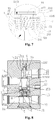
- Figure 8 shows another embodiment, a main difference between this embodiment and the above first embodiment lies in that: an upper end, opposite to the cavity, of the valve body is a closed structure, and a fourth cavity 157 is further provided above the cavity.
- a pressing block 10 is further provided at a portion where the first cavity is close to the fourth cavity
- the fourth cavity 157 is provided with a spring seat 9 and a third elastic element 33
- the third elastic element 33 has one end abutting against a bottom portion of the fourth cavity 157, and has another end abutting against a periphery of the spring seat 9, the third elastic element 33 and the spring seat 9 are confined in the fourth cavity via the pressing block 10 or a snap ring
- the third elastic element 33 here is in a compressed state. In this embodiment, leakage can be effectively prevented.
- Other structures and features in this embodiment may refer to the above embodiment.
- Figure 9 shows another embodiment, which differs from the above embodiments mainly in that: the second valve opening is not provided in the cavity, and the thermostatic actuating element 2 cannot close the first flow passage.
- the first flow passage always allows circulation of fluid during the moving process of the thermostatic actuating element 2, and in such a case, the thermostatic actuating element 2 may not be provided with the first sealing portion.
- Other structures and features in this embodiment may refer to the above embodiments.
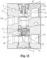
- Figure 11 shows another embodiment, which differs from the first embodiment mainly in the structure of the sealing cover 80, the structure of the valve body, a combining and fixing way of the sealing cover 80 and the valve body.
- An auxiliary cavity 158 is provided in the valve body 1 at an end opposite to the cap 5.
- the second port 12 is in communication with the auxiliary cavity 158, and a second valve opening 154 is provided between the auxiliary cavity 158 and the cavity 15.
- the piston 21 of the thermostatic actuating element or at least most part of the piston 21 is located in the auxiliary cavity 158.
- the sealing cover 80 is arranged in the valve body 1 by fitting a snap-fit component in a groove in an inner wall of the valve body, thus preventing the sealing cover 80 from escaping from the valve body 1, rather than being fixed by screw threads in the above embodiments.
- the inner wall portion of the valve body further has a step, to limit the movement of the sealing cover 80 inwards the auxiliary cavity of the valve body 1.
- the sealing over 80 is further provided at an end facing towards the second valve opening 154 with an accommodating cavity 801, and an end of the accommodating cavity 80 facing towards the second valve opening is open.
- the third elastic element 33 and the spring seat 9 are arranged in the accommodating cavity 801.
- the third elastic member 33 and the spring seat 9 are arranged in a concave portion of the accommodating cavity by a clamp spring to realize the position limiting.
- the top portion of the piston 21 of the thermostatic actuating element extends into a hole of the cap-shaped spring seat to abut against the third elastic element.
- the spring seat, the third elastic element may also be fixed in the accommodating cavity by other ways, for example, being tightly fitted in the accommodating cavity by a sealing cover to or being fixed to the accommodating cavity by welding.
- a cap 50 also includes a cap main body 506 configured to be fixed to the valve body.
- the cap main body 506 is provided with an external thread portion 501
- the valve body 1 is provided with an internal thread portion 101 in cooperation with the external thread portion 501 of the cap 50 at a portion, corresponding to the external thread portion 501, on an inner wall of the cavity, and the cap and the valve body are fixed to each other by a thread fit.
- the valve body 1 is provided with a position-limiting surface 102 configured to abut against the cap and limit a position of the cap, and the cap is also provided with a corresponding abutting surface 502.
- the abutting surface 502 abuts against the position-limiting surface 102 of the valve body to limit an axial position, thus ensuring a consistency of the product.
- the abutting surface of the cap, and the position-limiting surface of the valve body may also be provided at other positions such as in the cavity, as long as a corresponding stepped position-limiting surface is provided in the cavity, and the cap is also correspondingly provided with an abutting surface in cooperation with the stepped position-limiting surface of the cap. In this way, the cap 50 and the valve body 1 are connected and fixed by screw threads, and not be fixed by the snap ring.
- Other structures and implementation ways may refer to other embodiments introduced above.
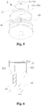
- the outer wall portion of the relief ring for discharging a high pressure is of a cylinder-type structure, moreover the outer wall portion may be of a structure in Figure 13 .
- a relief ring 70 has a bottom portion 77 and a side wall portion 76, and also has a communicating hole 71 in cooperation with the outer wall of the first valve seat 51, and a spring receiving portion 72.
- the bottom portion 77 includes a top portion 73 facing to the second cavity, and a bottom surface 74 configured to abut against the second elastic element 32.
- at least one annular recess 75 may be provided may be provided in an outer wall of the side wall portion 76 of the relief ring 70.
- the recess 75 between the relief ring 70 and an inner wall portion of the third cavity may be filled with fluid, and the fluid is used for lubrication, which allows the sliding between the relief ring and the inner wall of the third cavity to be reliable and stable.
- the assembling is relatively convenient.
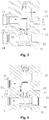
- the assembling is described taken the technical solution of the embodiment in Figure 14 as an example hereinafter, and Figure 14 is a schematic view showing the assembling process of the thermostatic valve in Figure 11 .
- the assembling process of the thermostatic valve includes the following steps.
- the components and parts include a valve body, a sealing cover, various elastic elements, a sealing ring, a snap ring, a thermostatic actuating element, a relief ring, and a cap.
- the components and parts according to this technical solution includes a valve body 1, a sealing cover 80, a third elastic member 33, a spring seat 9, a sealing ring, a snap ring 6, a snap ring 61, a snap ring 62, a thermostatic actuating element 2, a first elastic element 31, a second elastic element 32, a relief ring 7, and a cap 5.
- the assembling of the cap component includes assembling the sealing ring and the cap together;
- the assembling of the sealing cover component includes mounting the third elastic element 33 and the spring seat 9 into the cavity of the sealing cover 80, and using the snap ring 61to fix the third elastic element 33 and the spring seat, and sleeving and fixing the sealing ring on the sealing cover to form the sealing cover component.
- the above assembling step (30a) may also be as follows.
- the above assembling step (30a) may also be as follows.
- the thermostatic actuating element, the first elastic element 31 and the relief ring may also be assembled first, and after the components at the side of the cavity, such as the cap, are assembled, the sealing cover component is then assembled.
Landscapes
- Engineering & Computer Science (AREA)
- Physics & Mathematics (AREA)
- General Engineering & Computer Science (AREA)
- General Physics & Mathematics (AREA)
- Automation & Control Theory (AREA)
- Mechanical Engineering (AREA)
- Power Engineering (AREA)
- Fluid Mechanics (AREA)
- Temperature-Responsive Valves (AREA)
- Safety Valves (AREA)
- Ink Jet (AREA)
Claims (15)
- Soupape thermostatique comprenant un corps de soupape (1) avec une cavité (15) qui est prévue dans le corps de soupape (1), et un élément d'actionnement thermostatique et un premier élément élastique (31) monté dans la cavité (15), une extrémité de l'élément d'actionnement thermostatique étant supportée sur le premier élément élastique (31), le corps de soupape (1) comportant au moins trois orifices, et les trois orifices comprenant un premier orifice (11), un deuxième orifice (12) et un troisième orifice (14) ; dans laquelle :un premier siège de soupape (51) est en outre prévu dans la cavité (15), un diamètre externe du premier siège de soupape (51) est inférieur à un diamètre interne d'une partie correspondant au premier siège de soupape (51) de la cavité (15), il y a une distance entre un côté externe du premier siège de soupape (51) et un côté interne de la cavité (15) ;la soupape thermostatique étant caractérisée en ce que : elle comprend en outre une bague de décharge (7) et un deuxième élément élastique (32) dans la cavité (15), une extrémité du deuxième élément élastique (32) vient en butée contre la bague de décharge (7), au moins un premier passage est formé entre le premier siège de soupape (51) et la bague de décharge (7) ou entre le côté interne de la cavité (15) et la bague de décharge (7), dans la soupape thermostatique, le premier passage est débloqué ou bloqué par le mouvement de la bague de décharge (7) ; dans le cas où le premier passage est bloqué, la bague de décharge (7) est emmanchée sur le premier siège de soupape (51) ; et dans le cas où le premier passage est débloqué, la soupape thermostatique forme un troisième passage d'écoulement, et le troisième passage d'écoulement comprend un premier orifice (11), le premier passage et le troisième orifice (14) ; etla soupape thermostatique comprend en outre une première ouverture de soupape (511) au niveau du premier siège de soupape (51), dans la soupape thermostatique, la première ouverture de soupape (511) est ouverte ou fermée par le mouvement de l'élément d'actionnement thermostatique, dans le cas où l'élément d'actionnement thermostatique ouvre la première ouverture de soupape (511), le deuxième passage d'écoulement permet la circulation du fluide, et le deuxième passage d'écoulement comprend un premier orifice (11), la première ouverture de soupape (511) et le troisième orifice (14).
- Soupape thermostatique selon la revendication 1, dans laquelle la bague de décharge (7) comporte une partie de réception de ressort (72), la bague de décharge (7) a une partie inférieure (77) et une partie latérale (76), la partie inférieure (77) comprend une surface inférieure (74) et une partie supérieure (73) au niveau du côté arrière de la surface inférieure (74), une extrémité du deuxième élément élastique (32) vient en butée contre la surface inférieure (74) de la partie inférieure (77) de la bague de décharge (7), au moins une partie du côté interne de la cavité (15) est en coopération avec une course de la bague de décharge (7), et la bague de décharge (7) est en ajustement coulissant avec le côté interne de la cavité (15) au moins dans une partie partielle du côté interne de la cavité (15) ;
la partie supérieure (73) de la bague de décharge (7) est relativement plus proche du premier orifice (11) que la surface inférieure (74) de la bague de décharge (7), dans le cas où la première ouverture de soupape (511) est fermée, un espace au-dessus de la partie supérieure de la bague de décharge (7) de la cavité (15) est en communication avec le premier orifice (11), et un espace dans lequel le deuxième élément élastique (32) est positionné est en communication avec le troisième orifice (14) ; et
la soupape thermostatique comprend en outre un capuchon (5), le capuchon (5) est relativement fixe sur le corps de soupape (1), et au moins la moitié du capuchon (5) est positionnée dans la cavité (15), et une autre extrémité du premier élément élastique (31) et une autre extrémité du deuxième élément élastique (32) viennent respectivement en butée contre le capuchon (5). - Soupape thermostatique selon la revendication 2, dans laquelle la cavité (15) comprend une deuxième cavité (152) et une troisième cavité (153), un diamètre interne de la troisième cavité (153) est supérieur à un diamètre interne de la deuxième cavité (152), la deuxième cavité (152) est relativement plus proche du premier orifice (11) que la troisième cavité (153), le premier orifice (11) est en communication avec un espace où la deuxième cavité (152) est positionnée, et un espace où la troisième cavité (153) est positionnée est en communication avec le troisième orifice (14) ;
un gradin (1533) est formé entre la deuxième cavité (152) et la troisième cavité (153), la totalité ou au moins une partie de la bague de décharge (7), au moins une partie du premier siège de soupape (51) et au moins une partie du deuxième élément élastique (32) sont agencés dans la troisième cavité (153), dans le cas où la bague de décharge (7) vient en butée contre la gradin (1533), le premier passage est bloqué ; et
une partie latérale interne de la troisième cavité (153) ou une partie latérale externe de la bague de décharge (7) comporte au moins un évidement (1532) en communication avec le troisième orifice (14), dans le cas où la bague de décharge (7) ne vient pas en butée contre le gradin (1533) et il y a une distance entre la bague de décharge (7) et le gradin (1533), le premier passage est débloqué et le premier orifice (11) est en communication avec le troisième orifice (14) via l'évidement (1532). - Soupape thermostatique selon la revendication 2, dans laquelle la cavité (15) comprend une deuxième cavité (152) et une troisième cavité (153), un diamètre interne de la troisième cavité (153) est supérieur au diamètre interne de la deuxième cavité (152), la deuxième cavité (152) est plus proche du premier orifice (11) que la troisième cavité (153), le premier orifice (11) est en communication avec un espace où la deuxième cavité (152) est positionnée, et un espace où la troisième cavité (153) est positionnée est en communication avec le troisième orifice (14) ;
un gradin (1533) est formé entre la deuxième cavité (152) et la troisième cavité (153), la totalité ou au moins une partie de la bague de décharge (7), au moins une partie du premier siège de soupape (51) et au moins une partie du deuxième élément élastique (32) sont agencées dans la troisième cavité (153), dans le cas où la bague de décharge (7) vient en butée contre le gradin (1533), le premier passage est bloqué ;
la partie inférieure de la bague de décharge (7) comporte en outre un trou de communication (71), et le trou de communication (71) est en ajustement coulissant avec le premier siège de soupape (51), dans le cas où la bague de décharge (7) vient en butée contre le gradin (1533), la bague de décharge est emmanchée sur le premier siège de soupape (51), et une hauteur H1 du premier siège de soupape (51) en coopération avec la bague de décharge (7) est inférieure à une course coulissante H2 de la bague de décharge (7) le long d'une paroi interne de la troisième cavité (153) ; et
dans le cas où une pression différentielle entre la pression du côté supérieur et la pression du côté inférieur de la bague de décharge (7) amène une pression agissant sur la bague de décharge (7) à dépasser une force élastique du deuxième élément élastique (32), la bague de décharge (7) se déplace vers le troisième orifice (14), et permet à la partie inférieure de la bague de décharge (7) de sortir du premier siège de soupape (51), le premier passage est débloqué, et le premier orifice (11) est en communication avec le troisième orifice (14) via le premier passage et le premier trou de communication (71). - Soupape thermostatique selon la revendication 3 ou 4, dans laquelle la cavité (15) a une extrémité ouverte, et l'extrémité ouverte est plus proche du troisième orifice (14) que le premier orifice (11), l'extrémité ouverte de la cavité (15) est scellée par le capuchon (5) qui est monté de manière relativement fixe, ou l'extrémité ouverte de la cavité (15) est scellée par le capuchon (5) et une bague d'étanchéité qui sont montés de manière relativement fixe ;
le capuchon (5) comprend un premier siège de soupape (51), un siège de support (52) et un corps principal de capuchon (56), le siège de support (52) est positionné entre le premier siège de soupape (51) et le corps principal de capuchon (56), le corps principal de capuchon (56) est configuré pour coopérer avec l'extrémité ouverte du corps de soupape (1) pour l'étanchéité ; et
au moins une première partie de raccordement est en outre prévue entre le premier siège de soupape (51) et le siège de support (52), et au moins un passage configuré pour faire communiquer la troisième cavité (153) avec le troisième orifice (14), et une seconde partie de raccordement configurée pour raccorder le siège de support (52) et le corps principal de capuchon (56) sont en outre prévus entre le siège de support (52) et le corps principal de capuchon (56), et l'extrémité du premier élément élastique (31) et l'extrémité du deuxième élément élastique (52) viennent en butée contre le capuchon (5) en venant en butée contre le siège de support (52) du capuchon (5). - Soupape thermostatique selon la revendication 5, dans laquelle une surface d'extrémité supérieure orientée vers le premier siège de soupape (51) du siège de support (52) comprend une première surface de support (521) et une seconde surface de support (522), la seconde surface de support (522) est positionnée sur un côté externe de la surface d'extrémité supérieure, et la première surface de support (521) est positionnée au niveau d'un côté interne de la seconde surface de support (522), l'au moins une première partie de raccordement est positionnée entre la première surface de support (521) et la seconde surface de support (522), le premier élément élastique (31) vient en butée contre la première surface de support (521), le deuxième élément élastique (32) vient en butée contre la seconde surface de support (522), le siège de support (52) est en outre prévu avec un trou débouchant s'étendant à travers une surface d'extrémité supérieure du siège de support (52), un diamètre interne du trou débouchant est inférieur à un diamètre externe du premier élément élastique (31) et le diamètre externe du premier élément élastique (31) est inférieur à un diamètre interne de la première ouverture de soupape (511).
- Soupape thermostatique selon la revendication 6, la soupape thermostatique comportant en outre un troisième élément élastique (33) et deux extrémités de l'élément d'actionnement thermostatique viennent respectivement en butée contre le troisième élément élastique (33) et le premier élément élastique (31) ; et dans laquelle
l'élément d'actionnement thermostatique comprend un corps d'élément d'actionnement thermostatique et un piston (21), une extrémité de piston (21) vient directement ou indirectement en butée contre le troisième élément élastique (33), et le corps d'élément d'actionnement thermostatique vient directement ou indirectement en butée contre le premier élément élastique (31). - Soupape thermostatique selon la revendication 7, dans laquelle une cavité auxiliaire (155) est prévue dans le corps de soupape (1) au niveau d'un côté opposé à la cavité (15), le corps de soupape (1) comporte un trou (156) entre la cavité (15) et la cavité auxiliaire (155), et une partie supérieure du piston (21) s'étend à partir de la cavité (15) dans la cavité auxiliaire (155) via le trou (156) ; et
dans une direction allant d'une extrémité ouverte de la cavité auxiliaire (155) jusqu'à un intérieur, la soupape thermostatique est prévue dans la cavité auxiliaire (155) avec un couvercle d'étanchéité (8), le troisième élément élastique (33) et un siège de ressort (9) dans cet ordre, le siège de ressort (9) est une structure en forme de capuchon, et est emmanché sur une partie d'extrémité de la partie supérieure, s'étendant dans la cavité auxiliaire (155), du piston (21), et l'extrémité de la partie supérieure, s'étendant dans la cavité auxiliaire (155), du piston est positionnée dans une cavité interne du siège de ressort (9), le troisième élément élastique (33) a une extrémité venant en butée contre le couvercle d'étanchéité (8), et une autre extrémité venant en butée contre une périphérie du siège de ressort (9), et le troisième élément élastique (33) est dans un état comprimé. - Soupape thermostatique selon l'une quelconque des revendications 5 à 8, dans laquelle le corps de soupape (1) comprend en outre une première cavité (151), la deuxième cavité (152) est positionnée entre la première cavité (151) et la troisième cavité (153), le diamètre interne de la deuxième cavité (152) est supérieur à un diamètre interne de la première cavité (151), la première cavité (151) est en communication avec le deuxième orifice (12), une seconde ouverture de soupape (154) est prévue entre la première cavité (151) et la deuxième cavité (152) dans la soupape thermostatique, la seconde ouverture de soupape (154) est ouverte ou fermée par le mouvement de l'élément d'actionnement thermostatique, et dans le cas où l'élément d'actionnement thermostatique ouvre la seconde ouverture de soupape (154), le premier orifice (11) est en communication avec le deuxième orifice (12) via la seconde ouverture de soupape (154) pour former un premier passage d'écoulement.
- Soupape thermostatique selon l'une quelconque des revendications 3 à 9, dans laquelle le corps de soupape (1) comprend en outre une quatrième cavité (157), la première cavité (151) est positionnée entre la deuxième cavité (152) et la quatrième cavité (157), la troisième cavité (153), la deuxième cavité (152), la première cavité (151) et la quatrième cavité (157) sont agencées dans cet ordre à partir de l'extrémité ouverte de la cavité (15) jusqu'à un intérieur de la cavité (15) et les diamètres internes de la troisième cavité (153), de la deuxième cavité (152), de la première cavité (151) et de la quatrième cavité (157) sont réduits dans l'ordre, la quatrième cavité (157) comporte un siège de ressort (9) et un troisième élément élastique (33), et le siège de ressort (33) a une structure en forme de capuchon, le troisième élément élastique (33) a une première extrémité venant en butée contre une partie inférieure de la quatrième cavité (157), et une autre extrémité venant en butée contre une périphérie du siège de ressort (9), le troisième élément élastique (33) et le siège de ressort (9) sont fixés dans la quatrième cavité (157) via un bloc de pression (10) ou un anneau élastique, et le troisième élément élastique (33) est dans un état comprimé.
- Soupape thermostatique selon la revendication 10, dans laquelle l'élément d'actionnement thermostatique comprend en outre une première partie d'étanchéité (25) configurée pour ouvrir ou fermer la seconde ouverture de soupape (154), et une seconde partie d'étanchéité (23) configurée pour ouvrir ou fermer la première ouverture de soupape (511), un diamètre externe de la première partie d'étanchéité (25) est supérieur à un diamètre interne de la seconde ouverture de soupape (154), et un diamètre externe de la seconde partie d'étanchéité (23) est supérieur à un diamètre interne de la première ouverture de soupape (511), la première partie d'étanchéité (25) est plus à proximité du piston (21) que la seconde partie d'étanchéité (23) ; et
la première partie d'étanchéité (25) est montée, de manière fixe, sur une paroi externe du corps d'élément d'actionnement thermostatique ou est formée de manière solidaire avec la paroi externe du corps d'élément d'actionnement thermostatique ; et la seconde partie d'étanchéité (23) est montée, de manière fixe, sur la paroi externe du corps d'élément d'actionnement thermostatique ou est formée de manière solidaire avec la paroi externe du corps d'élément d'actionnement thermostatique. - Soupape thermostatique selon l'une quelconque des revendications 1 à 11, dans laquelle le long d'une direction axiale de l'élément d'actionnement thermique, une partie d'extrémité supérieure (512) orientée vers l'élément d'actionnement thermique, du premier siège de soupape (51) fait saillie au-dessus de la partie supérieure (73) de la partie inférieure, orientée vers l'élément d'actionnement thermique, de la bague de décharge (7).
- Soupape thermostatique selon l'une quelconque des revendications 1 à 7, dans laquelle le corps de soupape (1) comporte une cavité auxiliaire (158) au niveau d'un côté opposé à la cavité (15), et le corps de soupape (1) comporte un trou entre la cavité (15) et la cavité auxiliaire (158), l'élément d'actionnement thermique comprend un piston (21) et une partie supérieure du piston (21) s'étend à partir de la cavité (15) dans la cavité auxiliaire (158) via le trou ;
le corps de soupape (1) comporte une seconde ouverture de soupape (154) entre la cavité (15) et la cavité auxiliaire (158), l'élément d'actionnement thermique comporte une seconde partie d'étanchéité (23) en coopération avec la seconde ouverture de soupape (154), et le deuxième orifice (12) est en communication avec la cavité auxiliaire (158) ; et
la soupape thermostatique comprend en outre un couvercle d'étanchéité (80), un troisième élément élastique (33) et un siège de ressort (9), le couvercle d'étanchéité (80) comporte en outre, dans une direction vers la cavité (15), une partie de logement (801) qui est enfoncée vers l'intérieur, le troisième élément élastique (33) et le siège de ressort (9) sont positionnés dans la partie de logement (801), le siège de ressort (9) a une structure en forme de capuchon, une extrémité de la partie supérieure, s'étendant dans la cavité auxiliaire (158), du piston (21) s'étend dans la partie de logement (801), et le siège de ressort (9) est emmanché sur l'extrémité de la partie supérieure, s'étendant dans la cavité auxiliaire (158), du piston (21), le troisième élément élastique (33) a une extrémité venant en butée contre une partie inférieure de la partie de logement (801) du couvercle d'étanchéité (8), et une autre extrémité venant en butée contre une périphérie du siège de ressort (9), et le troisième élément élastique (33) est dans un état comprimé. - Soupape thermostatique selon l'une quelconque des revendications 1 à 13, dans laquelle la bague de décharge (7) a une partie inférieure (77) et une partie de paroi latérale (76), une extrémité du deuxième élément élastique (32) vient en butée contre la partie inférieure (77) de la bague de décharge (7), la partie de paroi latérale (76) de la bague de décharge (7) est en ajustement coulissant avec la paroi interne de la cavité (15), et un trou de communication (71) est prévu au niveau d'un centre de la partie inférieure (77) de la bague de décharge (7), le trou de communication (71) est légèrement supérieur à un diamètre externe d'une partie en coopération avec la bague de décharge (7) du premier siège de soupape (51) pour permettre à la bague de décharge (7) d'être en ajustement coulissant avec le premier siège de soupape (51), la bague de décharge (7) comporte en outre au moins un évidement annulaire (75) au niveau d'une paroi externe de la partie de paroi latérale (76), et il y a une distance entre l'évidement (75) de la bague de décharge (7), et une partie de paroi interne correspondant à l'évidement (75) de la cavité (15).
- Soupape thermostatique selon l'une quelconque des revendications 1 à 14, où la soupape thermostatique comprend en outre un capuchon (50), le capuchon (50) comprend un corps principal de capuchon (506) configuré pour être fixé au corps de soupape (1), le corps principal de capuchon (506) comporte une partie de filetage externe (501), le corps de soupape (1) comporte, au niveau de la paroi interne de la cavité (15), une partie de filetage interne (101) en coopération avec la partie de filetage externe (501) du capuchon (50), le capuchon (50) et le corps de soupape (1) sont fixés avec un ajustement par filetage, le corps de soupape (1) comporte une surface de limitation de position (102) configurée pour venir en butée contre le capuchon (50) et positionner ce dernier, le capuchon (50) comporte également une surface de butée (502) correspondante, la surface de butée (502) du capuchon (50) vient en butée contre la surface de limitation de position (102) du corps de soupape (1) ; et une autre extrémité du premier élément élastique (31) et une autre extrémité du deuxième élément élastique (32) viennent en butée contre le capuchon (50).
Priority Applications (1)
| Application Number | Priority Date | Filing Date | Title |
|---|---|---|---|
| PL16154111T PL3059405T3 (pl) | 2015-02-04 | 2016-02-03 | Zawór termostatyczny |
Applications Claiming Priority (2)
| Application Number | Priority Date | Filing Date | Title |
|---|---|---|---|
| CN201510058042 | 2015-02-04 | ||
| CN201610039674.1A CN105697748B (zh) | 2015-02-04 | 2016-01-20 | 调温器 |
Publications (2)
| Publication Number | Publication Date |
|---|---|
| EP3059405A1 EP3059405A1 (fr) | 2016-08-24 |
| EP3059405B1 true EP3059405B1 (fr) | 2019-05-29 |
Family
ID=56226672
Family Applications (1)
| Application Number | Title | Priority Date | Filing Date |
|---|---|---|---|
| EP16154111.5A Active EP3059405B1 (fr) | 2015-02-04 | 2016-02-03 | Soupape thermostatique |
Country Status (4)
| Country | Link |
|---|---|
| US (1) | US10241525B2 (fr) |
| EP (1) | EP3059405B1 (fr) |
| CN (1) | CN105697748B (fr) |
| PL (1) | PL3059405T3 (fr) |
Families Citing this family (15)
| Publication number | Priority date | Publication date | Assignee | Title |
|---|---|---|---|---|
| KR20180065028A (ko) * | 2015-10-27 | 2018-06-15 | 다나 캐나다 코포레이션 | 다단식 바이패스 밸브 |
| CN107314150B (zh) * | 2016-04-26 | 2019-09-17 | 浙江三花汽车零部件有限公司 | 调温阀 |
| US10690042B2 (en) * | 2016-09-27 | 2020-06-23 | Ford Global Technologies, Llc | Methods and systems for coolant system |
| DE102016221601A1 (de) * | 2016-11-03 | 2018-05-03 | Bayerische Motoren Werke Aktiengesellschaft | Thermostat für einen Getriebeölkreislauf und Getriebeölkreislauf |
| CN108068581B (zh) * | 2016-11-09 | 2022-12-20 | 杭州三花研究院有限公司 | 流体换热组件及车辆热管理系统 |
| CN108266566B (zh) * | 2017-01-03 | 2019-08-23 | 浙江三花汽车零部件有限公司 | 一种调温阀 |
| CN108266520B (zh) * | 2017-01-03 | 2021-02-09 | 浙江三花汽车零部件有限公司 | 一种调温阀 |
| CN108266568B (zh) * | 2017-01-03 | 2019-08-23 | 浙江三花汽车零部件有限公司 | 一种热管理组件 |
| US10948930B2 (en) | 2017-01-03 | 2021-03-16 | Zhejiang Sanhua Automotive Components Co., Ltd. | Thermostatic valve and thermal management assembly having same |
| DE102018004082B4 (de) * | 2017-05-24 | 2023-07-06 | Mann+Hummel Gmbh | Schaltventil zum Einstellen eines Fluidstroms |
| CN109555843A (zh) * | 2017-09-27 | 2019-04-02 | 浙江三花汽车零部件有限公司 | 阀组件、热交换装置和变速箱油温度调节系统 |
| CN112413169B (zh) * | 2019-08-23 | 2023-01-17 | 广汽埃安新能源汽车有限公司 | 温控阀及温控装置 |
| CN112747167B (zh) * | 2019-10-29 | 2023-01-24 | 浙江三花汽车零部件有限公司 | 一种调温阀 |
| CA3218945A1 (fr) * | 2021-05-14 | 2022-11-17 | Dean Mason | Soupape regulatrice de derivation thermique pour un bloc de conduites de refroidissement avec canaux decales pour une conduite de sortie |
| CN114264686B (zh) * | 2022-02-28 | 2022-05-31 | 深圳市汇恒自动化科技有限公司 | 保温密封排气结构及高低温湿热测试装置 |
Family Cites Families (9)
| Publication number | Priority date | Publication date | Assignee | Title |
|---|---|---|---|---|
| US7299994B2 (en) * | 2001-08-31 | 2007-11-27 | Huron, Inc. | Oil cooler bypass valve |
| US8141790B2 (en) * | 2008-11-21 | 2012-03-27 | Dana Canada Corporation | Thermal bypass valve with pressure relief capability |
| US8069661B2 (en) | 2009-02-24 | 2011-12-06 | GM Global Technology Operations LLC | Transmission hydraulic control system having an accumulator |
| CN102359577A (zh) * | 2011-09-08 | 2012-02-22 | 浙江三花汽车零部件股份有限公司 | 一种车用变速箱调温器 |
| CN103133740B (zh) * | 2011-12-04 | 2015-01-28 | 浙江三花汽车零部件有限公司 | 一种调温器及其阀体的制作方法 |
| CN103573993B (zh) * | 2012-08-07 | 2016-05-25 | 浙江三花汽车零部件有限公司 | 一种用于换热回路的调温器 |
| US10007281B2 (en) | 2012-08-07 | 2018-06-26 | Zhejiang Sanhua Automotive Components Co., Ltd. | Thermoregulator |
| CN103574265B (zh) * | 2012-08-07 | 2016-08-17 | 浙江三花汽车零部件有限公司 | 一种用于换热回路的调温器 |
| CN103851169A (zh) * | 2012-11-28 | 2014-06-11 | 浙江三花汽车零部件有限公司 | 一种调温器 |
-
2016
- 2016-01-20 CN CN201610039674.1A patent/CN105697748B/zh active Active
- 2016-02-03 PL PL16154111T patent/PL3059405T3/pl unknown
- 2016-02-03 EP EP16154111.5A patent/EP3059405B1/fr active Active
- 2016-02-04 US US15/015,450 patent/US10241525B2/en active Active
Non-Patent Citations (1)
| Title |
|---|
| None * |
Also Published As
| Publication number | Publication date |
|---|---|
| US10241525B2 (en) | 2019-03-26 |
| US20160224037A1 (en) | 2016-08-04 |
| CN105697748B (zh) | 2017-11-21 |
| CN105697748A (zh) | 2016-06-22 |
| PL3059405T3 (pl) | 2020-03-31 |
| EP3059405A1 (fr) | 2016-08-24 |
Similar Documents
| Publication | Publication Date | Title |
|---|---|---|
| EP3059405B1 (fr) | Soupape thermostatique | |
| US9541211B2 (en) | Thermoregulator and thermoregulator component | |
| EP3467352B1 (fr) | Soupape de régulation de température | |
| KR101682506B1 (ko) | 온도조절장치 | |
| KR102103337B1 (ko) | 서모스탯 및 온도 제어 시스템 | |
| KR102380176B1 (ko) | 밸브 조립체, 열교환 조립체, 및 기어박스용 오일온도조절 시스템 | |
| CN108087530B (zh) | 热交换组件 | |
| KR102288080B1 (ko) | 변속기 오일의 온도를 조정하기 위한 시스템, 열 교환 조립체 및 밸브 조립체 | |
| EP3567281B1 (fr) | Soupape de régulation de température et ensemble de gestion thermique doté de celle-ci | |
| CN107304834B (zh) | 一种温控系统 | |
| EP3812633B1 (fr) | Vanne de réglage de température | |
| CN108087532B (zh) | 热交换组件 | |
| CN108087531B (zh) | 热交换组件 | |
| EP3467364B1 (fr) | Vanne de régulation de température | |
| CN108930777B (zh) | 调温阀 | |
| CN110799776B (zh) | 调温阀 | |
| CN108087579B (zh) | 阀组件 | |
| KR102374605B1 (ko) | 열교환기 |
Legal Events
| Date | Code | Title | Description |
|---|---|---|---|
| PUAI | Public reference made under article 153(3) epc to a published international application that has entered the european phase |
Free format text: ORIGINAL CODE: 0009012 |
|
| AK | Designated contracting states |
Kind code of ref document: A1 Designated state(s): AL AT BE BG CH CY CZ DE DK EE ES FI FR GB GR HR HU IE IS IT LI LT LU LV MC MK MT NL NO PL PT RO RS SE SI SK SM TR |
|
| AX | Request for extension of the european patent |
Extension state: BA ME |
|
| RIN1 | Information on inventor provided before grant (corrected) |
Inventor name: YIN, BIN Inventor name: QIU, HAOMING Inventor name: QIAN, XIAOJUN |
|
| STAA | Information on the status of an ep patent application or granted ep patent |
Free format text: STATUS: REQUEST FOR EXAMINATION WAS MADE |
|
| 17P | Request for examination filed |
Effective date: 20170105 |
|
| RBV | Designated contracting states (corrected) |
Designated state(s): AL AT BE BG CH CY CZ DE DK EE ES FI FR GB GR HR HU IE IS IT LI LT LU LV MC MK MT NL NO PL PT RO RS SE SI SK SM TR |
|
| GRAP | Despatch of communication of intention to grant a patent |
Free format text: ORIGINAL CODE: EPIDOSNIGR1 |
|
| STAA | Information on the status of an ep patent application or granted ep patent |
Free format text: STATUS: GRANT OF PATENT IS INTENDED |
|
| RIC1 | Information provided on ipc code assigned before grant |
Ipc: F01P 7/16 20060101ALI20181113BHEP Ipc: F16H 57/04 20100101ALN20181113BHEP Ipc: G05D 16/10 20060101ALI20181113BHEP Ipc: G05D 23/185 20060101ALI20181113BHEP Ipc: F01M 5/00 20060101AFI20181113BHEP |
|
| INTG | Intention to grant announced |
Effective date: 20181214 |
|
| RIC1 | Information provided on ipc code assigned before grant |
Ipc: F01P 7/16 20060101ALI20181203BHEP Ipc: G05D 23/185 20060101ALI20181203BHEP Ipc: G05D 16/10 20060101ALI20181203BHEP Ipc: F01M 5/00 20060101AFI20181203BHEP Ipc: F16H 57/04 20100101ALN20181203BHEP |
|
| GRAS | Grant fee paid |
Free format text: ORIGINAL CODE: EPIDOSNIGR3 |
|
| GRAA | (expected) grant |
Free format text: ORIGINAL CODE: 0009210 |
|
| STAA | Information on the status of an ep patent application or granted ep patent |
Free format text: STATUS: THE PATENT HAS BEEN GRANTED |
|
| AK | Designated contracting states |
Kind code of ref document: B1 Designated state(s): AL AT BE BG CH CY CZ DE DK EE ES FI FR GB GR HR HU IE IS IT LI LT LU LV MC MK MT NL NO PL PT RO RS SE SI SK SM TR |
|
| REG | Reference to a national code |
Ref country code: GB Ref legal event code: FG4D |
|
| REG | Reference to a national code |
Ref country code: CH Ref legal event code: EP |
|
| REG | Reference to a national code |
Ref country code: AT Ref legal event code: REF Ref document number: 1138390 Country of ref document: AT Kind code of ref document: T Effective date: 20190615 |
|
| REG | Reference to a national code |
Ref country code: DE Ref legal event code: R096 Ref document number: 602016014491 Country of ref document: DE |
|
| REG | Reference to a national code |
Ref country code: IE Ref legal event code: FG4D |
|
| REG | Reference to a national code |
Ref country code: NL Ref legal event code: MP Effective date: 20190529 |
|
| REG | Reference to a national code |
Ref country code: LT Ref legal event code: MG4D |
|
| PG25 | Lapsed in a contracting state [announced via postgrant information from national office to epo] |
Ref country code: NO Free format text: LAPSE BECAUSE OF FAILURE TO SUBMIT A TRANSLATION OF THE DESCRIPTION OR TO PAY THE FEE WITHIN THE PRESCRIBED TIME-LIMIT Effective date: 20190829 Ref country code: FI Free format text: LAPSE BECAUSE OF FAILURE TO SUBMIT A TRANSLATION OF THE DESCRIPTION OR TO PAY THE FEE WITHIN THE PRESCRIBED TIME-LIMIT Effective date: 20190529 Ref country code: LT Free format text: LAPSE BECAUSE OF FAILURE TO SUBMIT A TRANSLATION OF THE DESCRIPTION OR TO PAY THE FEE WITHIN THE PRESCRIBED TIME-LIMIT Effective date: 20190529 Ref country code: AL Free format text: LAPSE BECAUSE OF FAILURE TO SUBMIT A TRANSLATION OF THE DESCRIPTION OR TO PAY THE FEE WITHIN THE PRESCRIBED TIME-LIMIT Effective date: 20190529 Ref country code: PT Free format text: LAPSE BECAUSE OF FAILURE TO SUBMIT A TRANSLATION OF THE DESCRIPTION OR TO PAY THE FEE WITHIN THE PRESCRIBED TIME-LIMIT Effective date: 20190930 Ref country code: ES Free format text: LAPSE BECAUSE OF FAILURE TO SUBMIT A TRANSLATION OF THE DESCRIPTION OR TO PAY THE FEE WITHIN THE PRESCRIBED TIME-LIMIT Effective date: 20190529 Ref country code: SE Free format text: LAPSE BECAUSE OF FAILURE TO SUBMIT A TRANSLATION OF THE DESCRIPTION OR TO PAY THE FEE WITHIN THE PRESCRIBED TIME-LIMIT Effective date: 20190529 Ref country code: HR Free format text: LAPSE BECAUSE OF FAILURE TO SUBMIT A TRANSLATION OF THE DESCRIPTION OR TO PAY THE FEE WITHIN THE PRESCRIBED TIME-LIMIT Effective date: 20190529 |
|
| PG25 | Lapsed in a contracting state [announced via postgrant information from national office to epo] |
Ref country code: LV Free format text: LAPSE BECAUSE OF FAILURE TO SUBMIT A TRANSLATION OF THE DESCRIPTION OR TO PAY THE FEE WITHIN THE PRESCRIBED TIME-LIMIT Effective date: 20190529 Ref country code: GR Free format text: LAPSE BECAUSE OF FAILURE TO SUBMIT A TRANSLATION OF THE DESCRIPTION OR TO PAY THE FEE WITHIN THE PRESCRIBED TIME-LIMIT Effective date: 20190830 Ref country code: BG Free format text: LAPSE BECAUSE OF FAILURE TO SUBMIT A TRANSLATION OF THE DESCRIPTION OR TO PAY THE FEE WITHIN THE PRESCRIBED TIME-LIMIT Effective date: 20190829 Ref country code: RS Free format text: LAPSE BECAUSE OF FAILURE TO SUBMIT A TRANSLATION OF THE DESCRIPTION OR TO PAY THE FEE WITHIN THE PRESCRIBED TIME-LIMIT Effective date: 20190529 |
|
| REG | Reference to a national code |
Ref country code: AT Ref legal event code: MK05 Ref document number: 1138390 Country of ref document: AT Kind code of ref document: T Effective date: 20190529 |
|
| PG25 | Lapsed in a contracting state [announced via postgrant information from national office to epo] |
Ref country code: SK Free format text: LAPSE BECAUSE OF FAILURE TO SUBMIT A TRANSLATION OF THE DESCRIPTION OR TO PAY THE FEE WITHIN THE PRESCRIBED TIME-LIMIT Effective date: 20190529 Ref country code: EE Free format text: LAPSE BECAUSE OF FAILURE TO SUBMIT A TRANSLATION OF THE DESCRIPTION OR TO PAY THE FEE WITHIN THE PRESCRIBED TIME-LIMIT Effective date: 20190529 Ref country code: RO Free format text: LAPSE BECAUSE OF FAILURE TO SUBMIT A TRANSLATION OF THE DESCRIPTION OR TO PAY THE FEE WITHIN THE PRESCRIBED TIME-LIMIT Effective date: 20190529 Ref country code: NL Free format text: LAPSE BECAUSE OF FAILURE TO SUBMIT A TRANSLATION OF THE DESCRIPTION OR TO PAY THE FEE WITHIN THE PRESCRIBED TIME-LIMIT Effective date: 20190529 Ref country code: CZ Free format text: LAPSE BECAUSE OF FAILURE TO SUBMIT A TRANSLATION OF THE DESCRIPTION OR TO PAY THE FEE WITHIN THE PRESCRIBED TIME-LIMIT Effective date: 20190529 Ref country code: AT Free format text: LAPSE BECAUSE OF FAILURE TO SUBMIT A TRANSLATION OF THE DESCRIPTION OR TO PAY THE FEE WITHIN THE PRESCRIBED TIME-LIMIT Effective date: 20190529 Ref country code: DK Free format text: LAPSE BECAUSE OF FAILURE TO SUBMIT A TRANSLATION OF THE DESCRIPTION OR TO PAY THE FEE WITHIN THE PRESCRIBED TIME-LIMIT Effective date: 20190529 |
|
| PG25 | Lapsed in a contracting state [announced via postgrant information from national office to epo] |
Ref country code: SM Free format text: LAPSE BECAUSE OF FAILURE TO SUBMIT A TRANSLATION OF THE DESCRIPTION OR TO PAY THE FEE WITHIN THE PRESCRIBED TIME-LIMIT Effective date: 20190529 |
|
| REG | Reference to a national code |
Ref country code: DE Ref legal event code: R097 Ref document number: 602016014491 Country of ref document: DE |
|
| PG25 | Lapsed in a contracting state [announced via postgrant information from national office to epo] |
Ref country code: TR Free format text: LAPSE BECAUSE OF FAILURE TO SUBMIT A TRANSLATION OF THE DESCRIPTION OR TO PAY THE FEE WITHIN THE PRESCRIBED TIME-LIMIT Effective date: 20190529 |
|
| PLBE | No opposition filed within time limit |
Free format text: ORIGINAL CODE: 0009261 |
|
| STAA | Information on the status of an ep patent application or granted ep patent |
Free format text: STATUS: NO OPPOSITION FILED WITHIN TIME LIMIT |
|
| 26N | No opposition filed |
Effective date: 20200303 |
|
| PG25 | Lapsed in a contracting state [announced via postgrant information from national office to epo] |
Ref country code: SI Free format text: LAPSE BECAUSE OF FAILURE TO SUBMIT A TRANSLATION OF THE DESCRIPTION OR TO PAY THE FEE WITHIN THE PRESCRIBED TIME-LIMIT Effective date: 20190529 |
|
| REG | Reference to a national code |
Ref country code: CH Ref legal event code: PL |
|
| REG | Reference to a national code |
Ref country code: BE Ref legal event code: MM Effective date: 20200229 |
|
| PG25 | Lapsed in a contracting state [announced via postgrant information from national office to epo] |
Ref country code: LU Free format text: LAPSE BECAUSE OF NON-PAYMENT OF DUE FEES Effective date: 20200203 Ref country code: MC Free format text: LAPSE BECAUSE OF FAILURE TO SUBMIT A TRANSLATION OF THE DESCRIPTION OR TO PAY THE FEE WITHIN THE PRESCRIBED TIME-LIMIT Effective date: 20190529 |
|
| PG25 | Lapsed in a contracting state [announced via postgrant information from national office to epo] |
Ref country code: CH Free format text: LAPSE BECAUSE OF NON-PAYMENT OF DUE FEES Effective date: 20200229 Ref country code: LI Free format text: LAPSE BECAUSE OF NON-PAYMENT OF DUE FEES Effective date: 20200229 |
|
| PG25 | Lapsed in a contracting state [announced via postgrant information from national office to epo] |
Ref country code: IE Free format text: LAPSE BECAUSE OF NON-PAYMENT OF DUE FEES Effective date: 20200203 |
|
| PG25 | Lapsed in a contracting state [announced via postgrant information from national office to epo] |
Ref country code: BE Free format text: LAPSE BECAUSE OF NON-PAYMENT OF DUE FEES Effective date: 20200229 |
|
| PG25 | Lapsed in a contracting state [announced via postgrant information from national office to epo] |
Ref country code: MT Free format text: LAPSE BECAUSE OF FAILURE TO SUBMIT A TRANSLATION OF THE DESCRIPTION OR TO PAY THE FEE WITHIN THE PRESCRIBED TIME-LIMIT Effective date: 20190529 Ref country code: CY Free format text: LAPSE BECAUSE OF FAILURE TO SUBMIT A TRANSLATION OF THE DESCRIPTION OR TO PAY THE FEE WITHIN THE PRESCRIBED TIME-LIMIT Effective date: 20190529 |
|
| PG25 | Lapsed in a contracting state [announced via postgrant information from national office to epo] |
Ref country code: MK Free format text: LAPSE BECAUSE OF FAILURE TO SUBMIT A TRANSLATION OF THE DESCRIPTION OR TO PAY THE FEE WITHIN THE PRESCRIBED TIME-LIMIT Effective date: 20190529 Ref country code: IS Free format text: LAPSE BECAUSE OF FAILURE TO SUBMIT A TRANSLATION OF THE DESCRIPTION OR TO PAY THE FEE WITHIN THE PRESCRIBED TIME-LIMIT Effective date: 20190929 |
|
| PGFP | Annual fee paid to national office [announced via postgrant information from national office to epo] |
Ref country code: FR Payment date: 20230227 Year of fee payment: 8 |
|
| PGFP | Annual fee paid to national office [announced via postgrant information from national office to epo] |
Ref country code: PL Payment date: 20230120 Year of fee payment: 8 Ref country code: IT Payment date: 20230209 Year of fee payment: 8 |
|
| P01 | Opt-out of the competence of the unified patent court (upc) registered |
Effective date: 20230526 |
|
| PGFP | Annual fee paid to national office [announced via postgrant information from national office to epo] |
Ref country code: DE Payment date: 20240213 Year of fee payment: 9 Ref country code: GB Payment date: 20240221 Year of fee payment: 9 |