EP3059137B1 - Dispositif d'absorption de choc pour un dispositif d'attelage de véhicule ferroviaire - Google Patents
Dispositif d'absorption de choc pour un dispositif d'attelage de véhicule ferroviaire Download PDFInfo
- Publication number
- EP3059137B1 EP3059137B1 EP16155295.5A EP16155295A EP3059137B1 EP 3059137 B1 EP3059137 B1 EP 3059137B1 EP 16155295 A EP16155295 A EP 16155295A EP 3059137 B1 EP3059137 B1 EP 3059137B1
- Authority
- EP
- European Patent Office
- Prior art keywords
- damping device
- longitudinal direction
- guide bar
- bearing plate
- fusible
- Prior art date
- Legal status (The legal status is an assumption and is not a legal conclusion. Google has not performed a legal analysis and makes no representation as to the accuracy of the status listed.)
- Active
Links
Images
Classifications
-
- B—PERFORMING OPERATIONS; TRANSPORTING
- B61—RAILWAYS
- B61G—COUPLINGS; DRAUGHT AND BUFFING APPLIANCES
- B61G11/00—Buffers
- B61G11/16—Buffers absorbing shocks by permanent deformation of buffer element
-
- B—PERFORMING OPERATIONS; TRANSPORTING
- B61—RAILWAYS
- B61D—BODY DETAILS OR KINDS OF RAILWAY VEHICLES
- B61D15/00—Other railway vehicles, e.g. scaffold cars; Adaptations of vehicles for use on railways
- B61D15/06—Buffer cars; Arrangements or construction of railway vehicles for protecting them in case of collisions
Definitions
- the present invention relates to an energy absorption device in the event of an impact for a rail vehicle coupling device.
- a coupling device ensures the connection between two cars of a railway vehicle, by transmitting a traction or pushing force from one car to another. However, in the event of an impact, the coupling must clear to allow the interlocking devices to be engaged and / or absorb all or part of the collision energy.
- the guide bar has a variable section, between a small section and a large section, and the support plate has a passage orifice of diameter corresponding to the small section of the bar.
- each bar performs both a function of guiding the support plate, and a function of absorbing the impact energy.
- a bar usually has a relatively high mass, since it must withstand the machining forces and provide guidance.
- the object of the invention is in particular to reduce the mass of a shock absorption device, without impairing its effectiveness.
- the subject of the invention is in particular a shock absorption device according to claim 1.
- each guide bar fulfills only one guiding function.
- this guide bar has a large mass, unlike a guide bar of the prior art.
- the mass of each guide bar can therefore be reduced, which therefore reduces the overall mass of the absorption device according to the invention.
- the invention also relates to a railway vehicle car comprising a coupling device extending in a longitudinal direction, characterized in that it comprises an absorption device as defined above, and a housing for the absorption device , said housing comprising a bottom structural wall arranged opposite the second support plate in the longitudinal direction.
- the coupling device sinks into said housing, absorbing the impact by deformation of the energy absorption means.
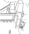
- the car 10 comprises a structural body 12 of the conventional type, shown cut along a longitudinal direction X.
- the structural box 12 is intended to carry a coupling device 14 (shown in the figure 2 ), as well as a shock absorption device 16 linked to this coupling device 14.
- the structural body 12 comprises a housing 18, for example formed in a central part of this structural body 12, intended to house the shock absorption device 16.
- the housing 18 extends in the longitudinal direction X between a mouth 20 and a bottom structural wall 22, and has side walls 24, extending between the mouth 20 and the bottom structural wall 22, laterally closing the housing 18.
- the structural box 12 also comprises buffers 26, 28 of conventional types, arranged on either side of the housing 18 in a transverse direction Y perpendicular to the longitudinal direction X.
- the coupling device 14 is of the conventional type, and will therefore not be described in detail. This coupling device 14 extends in the longitudinal direction X, in front of the structural box 12 when it is attached to this structural box 12.
- the shock absorption device 16 also extends in the longitudinal direction X, in the extension of the coupling device 14, when it is attached to the structural body 12.
- the shock absorption device 16 comprises a support member 30, intended to be fixed to a structural part of the car 10, and more particularly to the structural body 12, at the mouth 20 of the housing 18.
- This member support 30 is firmly fixed to this structural part, by conventional means (for example by screwing or welding), so that it remains fixed in the event of impact.
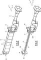
- the shock absorption device 16 also comprises at least one guide bar 32 (visible on the figure 3 ), extending in the longitudinal direction between a first end 32A fixed to the support member 30, and a second end 32B.
- the absorption device 16 comprises two guide bars 32 parallel to each other. These two guide bars 32 are spaced from each other by a transverse spacing greater than a transverse dimension of a part of the coupling device 14 capable of sinking into the housing 18 in the event of an impact. Thus, this part of the coupling device 14 can move between the guide bars 32, without being hindered by these guide bars 32.
- each guide bar 32 has a circular cross section, but it could alternatively have any other form of cross section, for example rectangular.
- the absorption device 16 also comprises a first support plate 34, intended to cooperate with the coupling device 14, movable along the guide bars 32.
- the first support plate 34 comprises, for each guide bar 32, a passage opening of this guide bar 32, capable of sliding along this guide bar 32.
- the dimensions and the shape of the passage opening are complementary to those of the guide bar. corresponding guide 32.
- the coupling device 14 usually comprises an end plate (not shown) for its attachment to the first support plate 34.
- the coupling device 14 moves with this first support plate 34.
- the first support plate 34 is driven along the guide bars 32 by the coupling device 14, when the latter transmits the energy of an impact.
- the end plate has a transverse dimension less than the transverse spacing between the guide bars 32, in order to be able to move between them.
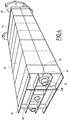
- the absorption device 16 comprises a second support plate 36, arranged at a distance from the first support plate 34 in the longitudinal direction X.
- the second end 32B of each guide bar 32 is fused with this second plate support 36, by fuse fixing means 38.
- fuse fixing means 38 are capable of breaking, thereby releasing the second end 32B of each guide bar 32, when they receive the energy of an impact. For example, these fuse fixing means 38 break when they undergo a longitudinal force of the order of 50 to 100 kN.
- the second support plate 36 is arranged opposite the bottom structural wall 22 when the absorption device 16 is housed in the housing 18. This bottom structural wall 22 is then spaced from the second support plate 36 with a longitudinal spacing of about fifteen millimeters due to the construction tolerances of the various sub-assemblies involved in this assembly. Thus, when the fuse fixing means 38 break, the second support plate 36 comes into contact with the bottom structural wall 22.
- the second support plate 36 advantageously comprises ribs 40 extending in the longitudinal direction X, therefore in the direction of the bottom structural wall 22, intended to come into contact with this bottom structural wall 22 when the fixing means fuses 38 break.
- the fuse fixing means 38 comprise a threaded part 42 formed at the second end 32B of each guide bar 32 and, for each guide bar 32, a fuse nut 44 screwed onto the threaded part 42 corresponding.
- the second support plate 36 then has, for each guide bar 32, a complementary passage opening, said threaded portion 42 extending beyond this passage opening, as shown in the figure 4 .
- Each fuse nut 44 has at least one part of less resistance, to ensure that it breaks in the event of an impact.
- each fusible nut 44 comprises at least two parts of least resistance, for example four. Thus, it is ensured that the fusible nut 44 breaks into several pieces, and that it therefore separates from the corresponding threaded part 42.
- each fusible nut 44 is made of plastic material in order to obtain a low breaking force, despite the large diameter of the nut, while ensuring the assembly of the rear part of the system under normal operating conditions.
- the absorption device 16 finally comprises means 46 for absorbing the energy of an impact by deformation, distinct from the guide bars 32, extending in the longitudinal direction X between the first support plate 34 and the second support plate 36.
- These absorption means 46 are on the one hand bearing against the first support plate 34, and on the other hand bearing against the second support plate 36, so that they deform, in particular by crushing, when the first support plate 34 moves, along the guide bars 32, towards the second support plate 36.
- the energy absorption means 46 are at least partially hollow, so that they comprise a passage for each guide bar 32, each guide bar 32 being housed in the respective passage.
- the energy absorption means 46 are therefore held transversely relative to the support member 30 by the guide bars 32. Because the guide bars 32 are arranged in the energy absorption means 46, these energy absorption means 46 are not shown on the figure 3 to allow these guide bars 32 to be viewed. They are, however, visible on the figure 2 and the figure 4 .
- the energy absorption means 46 comprise a plurality of honeycomb structures 47 stacked in the longitudinal direction X.
- they could comprise only a honeycomb structure, or any other type of conventional damping box.
- shock absorption device 16 The operation of the shock absorption device 16 will now be described.
- the shock absorption device 16 is housed in the housing 18, its support member 30 being fixed at the mouth 20, and its second support plate 36 being arranged opposite the structural wall background 22.
- the coupling device 14 applies a thrust force to the first support plate 34, which is carried over to the second support plate 36 by the absorption means 46.
- the second support plate 36 is retained by the guide bars 32, by the fuse fixing means 38.
- the resistance of the fuse fixing means 38 is low, and more particularly is significantly lower than the resistance to deformation of the absorption means 46.
- the fuse fixing means 38 break under the effect of this thrust force, releasing the fixing between the guide bars 32 and the second support plate 36.
- the second support plate 36 is then free to move in the longitudinal direction X under the effect of the thrust force, so that it moves until it comes into contact with the bottom structural surface 22.
- This second support plate 36 in contact with the bottom structural surface 22 is then firmly immobilized in the longitudinal direction X.
- the first support plate 34 As for the first support plate 34, it is still subjected to the pushing force of the coupling device 14, and therefore moves in the longitudinal direction X, guided by the guide bars 32.
- the first support plate 34 compresses the absorption means 46 against the second immobilized support plate 36, thus causing the deformation of these absorption means 46.
- the energy of the impact is then used to deform these absorption means 46.
- the coupling device 14 thus sinks into the housing 18, deforming the absorption means 46, until all of the impact energy is absorbed or, more frequently, until the pads 26, 28 come into contact with complementary pads carried by another car which is connected to it by the coupling device 14.
- each guide bar 32 may have a cross section of diameter less than 65 mm.
- the overall mass of the shock absorption device 16 is reduced. More particularly, this overall mass can reach approximately 200 kg for a shock absorption device 16 according to the invention, while that of an absorption device of the state of the art is generally approximately 280 kg.
Landscapes
- Engineering & Computer Science (AREA)
- Mechanical Engineering (AREA)
- Transportation (AREA)
- Vibration Dampers (AREA)
- Automotive Seat Belt Assembly (AREA)
Priority Applications (1)
| Application Number | Priority Date | Filing Date | Title |
|---|---|---|---|
| PL16155295T PL3059137T3 (pl) | 2015-02-17 | 2016-02-11 | Urządzenie pochłaniające wstrząsy dla urządzenia sprzęgającego pojazdu kolejowego |
Applications Claiming Priority (1)
| Application Number | Priority Date | Filing Date | Title |
|---|---|---|---|
| FR1551300A FR3032677B1 (fr) | 2015-02-17 | 2015-02-17 | Dispositif d'absorption de choc pour un dispositif d'attelage de vehicule ferroviaire |
Publications (2)
| Publication Number | Publication Date |
|---|---|
| EP3059137A1 EP3059137A1 (fr) | 2016-08-24 |
| EP3059137B1 true EP3059137B1 (fr) | 2020-01-01 |
Family
ID=53059264
Family Applications (1)
| Application Number | Title | Priority Date | Filing Date |
|---|---|---|---|
| EP16155295.5A Active EP3059137B1 (fr) | 2015-02-17 | 2016-02-11 | Dispositif d'absorption de choc pour un dispositif d'attelage de véhicule ferroviaire |
Country Status (4)
| Country | Link |
|---|---|
| EP (1) | EP3059137B1 (pl) |
| DK (1) | DK3059137T3 (pl) |
| FR (1) | FR3032677B1 (pl) |
| PL (1) | PL3059137T3 (pl) |
Cited By (1)
| Publication number | Priority date | Publication date | Assignee | Title |
|---|---|---|---|---|
| US12472998B2 (en) | 2020-09-30 | 2025-11-18 | Rxd—Research Exchange Development Ab | Energy dissipation device |
Families Citing this family (2)
| Publication number | Priority date | Publication date | Assignee | Title |
|---|---|---|---|---|
| CN115366940B (zh) * | 2022-08-29 | 2023-09-26 | 中南大学 | 一种具有自适应耐撞性保护装置的列车 |
| CN119329465A (zh) | 2023-07-20 | 2025-01-21 | 延锋汽车智能安全系统有限责任公司 | 活塞、安全带卷收器及预紧式安全带 |
Family Cites Families (4)
| Publication number | Priority date | Publication date | Assignee | Title |
|---|---|---|---|---|
| JP4966712B2 (ja) * | 2007-03-30 | 2012-07-04 | 株式会社日立製作所 | 輸送機 |
| WO2010029188A1 (de) * | 2008-09-15 | 2010-03-18 | Voith Patent Gmbh | Fahrzeugkopf zur befestigung an der stirnseite eines spurgebundenen fahrzeuges, insbesondere eines schienenfahrzeuges |
| DE102009034682A1 (de) * | 2009-07-24 | 2011-02-10 | Bombardier Transportation Gmbh | Schienenfahrzeug mit Crashabsorber-Anordnung, insbesondere Straßenbahn |
| PL217776B1 (pl) * | 2010-11-16 | 2014-08-29 | Axtone Spółka Z Ograniczoną Odpowiedzialnością | Zespół sprzęgowy do łączenia wagonów kolejowych |
-
2015
- 2015-02-17 FR FR1551300A patent/FR3032677B1/fr not_active Expired - Fee Related
-
2016
- 2016-02-11 PL PL16155295T patent/PL3059137T3/pl unknown
- 2016-02-11 DK DK16155295.5T patent/DK3059137T3/da active
- 2016-02-11 EP EP16155295.5A patent/EP3059137B1/fr active Active
Non-Patent Citations (1)
| Title |
|---|
| None * |
Cited By (1)
| Publication number | Priority date | Publication date | Assignee | Title |
|---|---|---|---|---|
| US12472998B2 (en) | 2020-09-30 | 2025-11-18 | Rxd—Research Exchange Development Ab | Energy dissipation device |
Also Published As
| Publication number | Publication date |
|---|---|
| DK3059137T3 (da) | 2020-03-30 |
| FR3032677B1 (fr) | 2017-03-31 |
| PL3059137T3 (pl) | 2020-06-29 |
| EP3059137A1 (fr) | 2016-08-24 |
| FR3032677A1 (fr) | 2016-08-19 |
Similar Documents
| Publication | Publication Date | Title |
|---|---|---|
| EP0802100B1 (fr) | Véhicule ferroviaire à cabinet de conduite comportant une structure absorbeuse d'énergie à déformation progressive | |
| EP1893469B1 (fr) | Voie basse guidee pour avant de vehicule automobile | |
| EP3059137B1 (fr) | Dispositif d'absorption de choc pour un dispositif d'attelage de véhicule ferroviaire | |
| EP1827943B1 (fr) | Dispositif absorbeur de chocs pour vehicule ferroviaire | |
| WO2023203288A1 (fr) | Véhicule automobile comprenant un longeron avec une pièce de renfort | |
| EP3083375B1 (fr) | Ensemble comportant une traverse de planche de bord pour véhicule automobile et deux supports latéraux permettant de fixer cette traverse à la caisse du véhicule | |
| EP1106467A1 (fr) | Dispositif de déformation contrôlée sous efforts ou d'absorption d'énergie par déformation, notamment déflecteur d'obstacles pour véhicule ferroviaire | |
| FR3123875A1 (fr) | Élément absorbeur de chocs pour véhicule automobile | |
| EP2881303B1 (fr) | Dispositif d'amortissement, notamment pour un dispositif d'attelage de véhicule ferroviaire | |
| EP1902907B1 (fr) | Dispositif d'absorption d'énergie pour poutre pare-chocs de véhicule automobile | |
| FR3009255A1 (fr) | Voie basse pour vehicule automobile | |
| EP3362334B1 (fr) | Composant de structure de véhicule automobile, et section de voie basse avant comprenant un tel composant | |
| FR3022603B1 (fr) | Dispositif absorbeur d'energie et vehicule correspondant | |
| FR2911824A1 (fr) | Ensemble d'absorption de chocs pour projecteur de vehicule automobile | |
| FR3081423A1 (fr) | Vehicule avec dispositif d’absorption a surface d’impact augmentant durant un choc. | |
| EP1930230A1 (fr) | Véhicule à cassette de refroidissement équipée d'au moins un élément d'absorption de choc frontal | |
| EP3172087B1 (fr) | Dispositif de voie basse pour véhicule automobile | |
| EP3172118B1 (fr) | Dispositif de voie basse pour véhicule automobile | |
| FR3071808B1 (fr) | Pied avant renforce de vehicule | |
| FR3012103A3 (fr) | Ensemble de voie avant de vehicule automobile | |
| EP2470399B1 (fr) | Support de pare-choc et pare-choc a deformations controlees | |
| WO2022243615A1 (fr) | Système de reprise d'effort sur une partie basse arrière d'un véhicule automobile | |
| FR3122377A1 (fr) | Traverse de pare-chocs | |
| EP3385150A1 (fr) | Renforcement de plancher de véhicule en cas de choc frontal à faible recouvrement | |
| FR2810602A1 (fr) | Poutre pare-chocs pour un vehicule automobile et face avant equipee de cette poutre pare-chocs |
Legal Events
| Date | Code | Title | Description |
|---|---|---|---|
| PUAI | Public reference made under article 153(3) epc to a published international application that has entered the european phase |
Free format text: ORIGINAL CODE: 0009012 |
|
| AK | Designated contracting states |
Kind code of ref document: A1 Designated state(s): AL AT BE BG CH CY CZ DE DK EE ES FI FR GB GR HR HU IE IS IT LI LT LU LV MC MK MT NL NO PL PT RO RS SE SI SK SM TR |
|
| AX | Request for extension of the european patent |
Extension state: BA ME |
|
| STAA | Information on the status of an ep patent application or granted ep patent |
Free format text: STATUS: REQUEST FOR EXAMINATION WAS MADE |
|
| 17P | Request for examination filed |
Effective date: 20170124 |
|
| RBV | Designated contracting states (corrected) |
Designated state(s): AL AT BE BG CH CY CZ DE DK EE ES FI FR GB GR HR HU IE IS IT LI LT LU LV MC MK MT NL NO PL PT RO RS SE SI SK SM TR |
|
| RIC1 | Information provided on ipc code assigned before grant |
Ipc: B61G 11/16 20060101AFI20190617BHEP |
|
| GRAP | Despatch of communication of intention to grant a patent |
Free format text: ORIGINAL CODE: EPIDOSNIGR1 |
|
| STAA | Information on the status of an ep patent application or granted ep patent |
Free format text: STATUS: GRANT OF PATENT IS INTENDED |
|
| INTG | Intention to grant announced |
Effective date: 20190726 |
|
| GRAS | Grant fee paid |
Free format text: ORIGINAL CODE: EPIDOSNIGR3 |
|
| GRAA | (expected) grant |
Free format text: ORIGINAL CODE: 0009210 |
|
| STAA | Information on the status of an ep patent application or granted ep patent |
Free format text: STATUS: THE PATENT HAS BEEN GRANTED |
|
| AK | Designated contracting states |
Kind code of ref document: B1 Designated state(s): AL AT BE BG CH CY CZ DE DK EE ES FI FR GB GR HR HU IE IS IT LI LT LU LV MC MK MT NL NO PL PT RO RS SE SI SK SM TR |
|
| REG | Reference to a national code |
Ref country code: GB Ref legal event code: FG4D Free format text: NOT ENGLISH |
|
| REG | Reference to a national code |
Ref country code: CH Ref legal event code: EP Ref country code: AT Ref legal event code: REF Ref document number: 1219442 Country of ref document: AT Kind code of ref document: T Effective date: 20200115 |
|
| REG | Reference to a national code |
Ref country code: DE Ref legal event code: R096 Ref document number: 602016027126 Country of ref document: DE |
|
| REG | Reference to a national code |
Ref country code: IE Ref legal event code: FG4D Free format text: LANGUAGE OF EP DOCUMENT: FRENCH |
|
| REG | Reference to a national code |
Ref country code: DK Ref legal event code: T3 Effective date: 20200324 |
|
| REG | Reference to a national code |
Ref country code: NL Ref legal event code: FP |
|
| REG | Reference to a national code |
Ref country code: LT Ref legal event code: MG4D |
|
| PG25 | Lapsed in a contracting state [announced via postgrant information from national office to epo] |
Ref country code: CZ Free format text: LAPSE BECAUSE OF FAILURE TO SUBMIT A TRANSLATION OF THE DESCRIPTION OR TO PAY THE FEE WITHIN THE PRESCRIBED TIME-LIMIT Effective date: 20200101 Ref country code: PT Free format text: LAPSE BECAUSE OF FAILURE TO SUBMIT A TRANSLATION OF THE DESCRIPTION OR TO PAY THE FEE WITHIN THE PRESCRIBED TIME-LIMIT Effective date: 20200527 Ref country code: LT Free format text: LAPSE BECAUSE OF FAILURE TO SUBMIT A TRANSLATION OF THE DESCRIPTION OR TO PAY THE FEE WITHIN THE PRESCRIBED TIME-LIMIT Effective date: 20200101 Ref country code: RS Free format text: LAPSE BECAUSE OF FAILURE TO SUBMIT A TRANSLATION OF THE DESCRIPTION OR TO PAY THE FEE WITHIN THE PRESCRIBED TIME-LIMIT Effective date: 20200101 Ref country code: NO Free format text: LAPSE BECAUSE OF FAILURE TO SUBMIT A TRANSLATION OF THE DESCRIPTION OR TO PAY THE FEE WITHIN THE PRESCRIBED TIME-LIMIT Effective date: 20200401 Ref country code: FI Free format text: LAPSE BECAUSE OF FAILURE TO SUBMIT A TRANSLATION OF THE DESCRIPTION OR TO PAY THE FEE WITHIN THE PRESCRIBED TIME-LIMIT Effective date: 20200101 |
|
| PG25 | Lapsed in a contracting state [announced via postgrant information from national office to epo] |
Ref country code: IS Free format text: LAPSE BECAUSE OF FAILURE TO SUBMIT A TRANSLATION OF THE DESCRIPTION OR TO PAY THE FEE WITHIN THE PRESCRIBED TIME-LIMIT Effective date: 20200501 Ref country code: GR Free format text: LAPSE BECAUSE OF FAILURE TO SUBMIT A TRANSLATION OF THE DESCRIPTION OR TO PAY THE FEE WITHIN THE PRESCRIBED TIME-LIMIT Effective date: 20200402 Ref country code: LV Free format text: LAPSE BECAUSE OF FAILURE TO SUBMIT A TRANSLATION OF THE DESCRIPTION OR TO PAY THE FEE WITHIN THE PRESCRIBED TIME-LIMIT Effective date: 20200101 Ref country code: HR Free format text: LAPSE BECAUSE OF FAILURE TO SUBMIT A TRANSLATION OF THE DESCRIPTION OR TO PAY THE FEE WITHIN THE PRESCRIBED TIME-LIMIT Effective date: 20200101 Ref country code: SE Free format text: LAPSE BECAUSE OF FAILURE TO SUBMIT A TRANSLATION OF THE DESCRIPTION OR TO PAY THE FEE WITHIN THE PRESCRIBED TIME-LIMIT Effective date: 20200101 Ref country code: BG Free format text: LAPSE BECAUSE OF FAILURE TO SUBMIT A TRANSLATION OF THE DESCRIPTION OR TO PAY THE FEE WITHIN THE PRESCRIBED TIME-LIMIT Effective date: 20200401 |
|
| REG | Reference to a national code |
Ref country code: CH Ref legal event code: PL |
|
| REG | Reference to a national code |
Ref country code: DE Ref legal event code: R097 Ref document number: 602016027126 Country of ref document: DE |
|
| PG25 | Lapsed in a contracting state [announced via postgrant information from national office to epo] |
Ref country code: EE Free format text: LAPSE BECAUSE OF FAILURE TO SUBMIT A TRANSLATION OF THE DESCRIPTION OR TO PAY THE FEE WITHIN THE PRESCRIBED TIME-LIMIT Effective date: 20200101 Ref country code: SM Free format text: LAPSE BECAUSE OF FAILURE TO SUBMIT A TRANSLATION OF THE DESCRIPTION OR TO PAY THE FEE WITHIN THE PRESCRIBED TIME-LIMIT Effective date: 20200101 Ref country code: ES Free format text: LAPSE BECAUSE OF FAILURE TO SUBMIT A TRANSLATION OF THE DESCRIPTION OR TO PAY THE FEE WITHIN THE PRESCRIBED TIME-LIMIT Effective date: 20200101 Ref country code: LU Free format text: LAPSE BECAUSE OF NON-PAYMENT OF DUE FEES Effective date: 20200211 Ref country code: RO Free format text: LAPSE BECAUSE OF FAILURE TO SUBMIT A TRANSLATION OF THE DESCRIPTION OR TO PAY THE FEE WITHIN THE PRESCRIBED TIME-LIMIT Effective date: 20200101 Ref country code: MC Free format text: LAPSE BECAUSE OF FAILURE TO SUBMIT A TRANSLATION OF THE DESCRIPTION OR TO PAY THE FEE WITHIN THE PRESCRIBED TIME-LIMIT Effective date: 20200101 Ref country code: SK Free format text: LAPSE BECAUSE OF FAILURE TO SUBMIT A TRANSLATION OF THE DESCRIPTION OR TO PAY THE FEE WITHIN THE PRESCRIBED TIME-LIMIT Effective date: 20200101 |
|
| PLBE | No opposition filed within time limit |
Free format text: ORIGINAL CODE: 0009261 |
|
| STAA | Information on the status of an ep patent application or granted ep patent |
Free format text: STATUS: NO OPPOSITION FILED WITHIN TIME LIMIT |
|
| PG25 | Lapsed in a contracting state [announced via postgrant information from national office to epo] |
Ref country code: CH Free format text: LAPSE BECAUSE OF NON-PAYMENT OF DUE FEES Effective date: 20200229 Ref country code: LI Free format text: LAPSE BECAUSE OF NON-PAYMENT OF DUE FEES Effective date: 20200229 |
|
| 26N | No opposition filed |
Effective date: 20201002 |
|
| PG25 | Lapsed in a contracting state [announced via postgrant information from national office to epo] |
Ref country code: IE Free format text: LAPSE BECAUSE OF NON-PAYMENT OF DUE FEES Effective date: 20200211 |
|
| PG25 | Lapsed in a contracting state [announced via postgrant information from national office to epo] |
Ref country code: SI Free format text: LAPSE BECAUSE OF FAILURE TO SUBMIT A TRANSLATION OF THE DESCRIPTION OR TO PAY THE FEE WITHIN THE PRESCRIBED TIME-LIMIT Effective date: 20200101 |
|
| GBPC | Gb: european patent ceased through non-payment of renewal fee |
Effective date: 20200401 |
|
| REG | Reference to a national code |
Ref country code: AT Ref legal event code: UEP Ref document number: 1219442 Country of ref document: AT Kind code of ref document: T Effective date: 20200101 |
|
| PG25 | Lapsed in a contracting state [announced via postgrant information from national office to epo] |
Ref country code: GB Free format text: LAPSE BECAUSE OF NON-PAYMENT OF DUE FEES Effective date: 20200401 |
|
| PG25 | Lapsed in a contracting state [announced via postgrant information from national office to epo] |
Ref country code: TR Free format text: LAPSE BECAUSE OF FAILURE TO SUBMIT A TRANSLATION OF THE DESCRIPTION OR TO PAY THE FEE WITHIN THE PRESCRIBED TIME-LIMIT Effective date: 20200101 Ref country code: MT Free format text: LAPSE BECAUSE OF FAILURE TO SUBMIT A TRANSLATION OF THE DESCRIPTION OR TO PAY THE FEE WITHIN THE PRESCRIBED TIME-LIMIT Effective date: 20200101 Ref country code: CY Free format text: LAPSE BECAUSE OF FAILURE TO SUBMIT A TRANSLATION OF THE DESCRIPTION OR TO PAY THE FEE WITHIN THE PRESCRIBED TIME-LIMIT Effective date: 20200101 |
|
| PG25 | Lapsed in a contracting state [announced via postgrant information from national office to epo] |
Ref country code: MK Free format text: LAPSE BECAUSE OF FAILURE TO SUBMIT A TRANSLATION OF THE DESCRIPTION OR TO PAY THE FEE WITHIN THE PRESCRIBED TIME-LIMIT Effective date: 20200101 Ref country code: AL Free format text: LAPSE BECAUSE OF FAILURE TO SUBMIT A TRANSLATION OF THE DESCRIPTION OR TO PAY THE FEE WITHIN THE PRESCRIBED TIME-LIMIT Effective date: 20200101 |
|
| P01 | Opt-out of the competence of the unified patent court (upc) registered |
Effective date: 20230823 |
|
| PGFP | Annual fee paid to national office [announced via postgrant information from national office to epo] |
Ref country code: PL Payment date: 20250131 Year of fee payment: 10 |
|
| REG | Reference to a national code |
Ref country code: BE Ref legal event code: PD Owner name: ALSTOM HOLDINGS; FR Free format text: DETAILS ASSIGNMENT: CHANGE OF OWNER(S), ASSIGNMENT; FORMER OWNER NAME: ALSTOM TRANSPORT TECHNOLOGIES Effective date: 20241025 |
|
| PGFP | Annual fee paid to national office [announced via postgrant information from national office to epo] |
Ref country code: NL Payment date: 20260218 Year of fee payment: 11 |
|
| PGFP | Annual fee paid to national office [announced via postgrant information from national office to epo] |
Ref country code: DK Payment date: 20260220 Year of fee payment: 11 Ref country code: DE Payment date: 20260218 Year of fee payment: 11 |
|
| PGFP | Annual fee paid to national office [announced via postgrant information from national office to epo] |
Ref country code: AT Payment date: 20260219 Year of fee payment: 11 |
|
| PGFP | Annual fee paid to national office [announced via postgrant information from national office to epo] |
Ref country code: BE Payment date: 20260218 Year of fee payment: 11 Ref country code: IT Payment date: 20260224 Year of fee payment: 11 |
|
| PGFP | Annual fee paid to national office [announced via postgrant information from national office to epo] |
Ref country code: FR Payment date: 20260218 Year of fee payment: 11 |