EP3058632B1 - Method and apparatus for producing a submarine cable, and submarine cable produced therewith - Google Patents
Method and apparatus for producing a submarine cable, and submarine cable produced therewith Download PDFInfo
- Publication number
- EP3058632B1 EP3058632B1 EP15704246.6A EP15704246A EP3058632B1 EP 3058632 B1 EP3058632 B1 EP 3058632B1 EP 15704246 A EP15704246 A EP 15704246A EP 3058632 B1 EP3058632 B1 EP 3058632B1
- Authority
- EP
- European Patent Office
- Prior art keywords
- cable protection
- protection tube
- cable
- conductors
- separation slot
- Prior art date
- Legal status (The legal status is an assumption and is not a legal conclusion. Google has not performed a legal analysis and makes no representation as to the accuracy of the status listed.)
- Active
Links
- 238000000034 method Methods 0.000 title claims description 18
- 239000004020 conductor Substances 0.000 claims description 66
- 238000000926 separation method Methods 0.000 claims description 30
- 238000009434 installation Methods 0.000 claims description 17
- 239000010410 layer Substances 0.000 claims description 17
- 238000007789 sealing Methods 0.000 claims description 17
- 229920003023 plastic Polymers 0.000 claims description 16
- 239000004033 plastic Substances 0.000 claims description 16
- 238000004519 manufacturing process Methods 0.000 claims description 12
- 239000000463 material Substances 0.000 claims description 10
- 150000001875 compounds Chemical class 0.000 claims description 9
- 238000005266 casting Methods 0.000 claims description 6
- 239000000126 substance Substances 0.000 claims description 5
- 239000012790 adhesive layer Substances 0.000 claims description 4
- 238000012432 intermediate storage Methods 0.000 claims description 3
- 230000014759 maintenance of location Effects 0.000 claims 3
- 230000002123 temporal effect Effects 0.000 claims 3
- 230000001681 protective effect Effects 0.000 description 30
- 238000003780 insertion Methods 0.000 description 10
- 230000037431 insertion Effects 0.000 description 10
- XLYOFNOQVPJJNP-UHFFFAOYSA-N water Substances O XLYOFNOQVPJJNP-UHFFFAOYSA-N 0.000 description 7
- 229920001903 high density polyethylene Polymers 0.000 description 6
- 239000004700 high-density polyethylene Substances 0.000 description 6
- 238000003466 welding Methods 0.000 description 6
- RYGMFSIKBFXOCR-UHFFFAOYSA-N Copper Chemical compound [Cu] RYGMFSIKBFXOCR-UHFFFAOYSA-N 0.000 description 5
- 239000010949 copper Substances 0.000 description 5
- 229910052802 copper Inorganic materials 0.000 description 5
- -1 Polyethylene Polymers 0.000 description 4
- 239000000853 adhesive Substances 0.000 description 4
- 238000004026 adhesive bonding Methods 0.000 description 4
- 230000001070 adhesive effect Effects 0.000 description 4
- 229910052782 aluminium Inorganic materials 0.000 description 4
- XAGFODPZIPBFFR-UHFFFAOYSA-N aluminium Chemical compound [Al] XAGFODPZIPBFFR-UHFFFAOYSA-N 0.000 description 4
- 230000005540 biological transmission Effects 0.000 description 4
- 238000005520 cutting process Methods 0.000 description 4
- 230000003287 optical effect Effects 0.000 description 4
- 238000004382 potting Methods 0.000 description 4
- 230000008569 process Effects 0.000 description 4
- 239000010426 asphalt Substances 0.000 description 3
- 238000005452 bending Methods 0.000 description 3
- 230000001419 dependent effect Effects 0.000 description 3
- 238000003860 storage Methods 0.000 description 3
- 239000004743 Polypropylene Substances 0.000 description 2
- 238000004891 communication Methods 0.000 description 2
- 238000011161 development Methods 0.000 description 2
- 230000018109 developmental process Effects 0.000 description 2
- 239000000835 fiber Substances 0.000 description 2
- 239000011521 glass Substances 0.000 description 2
- 239000003365 glass fiber Substances 0.000 description 2
- 229910052751 metal Inorganic materials 0.000 description 2
- 239000002184 metal Substances 0.000 description 2
- 238000003801 milling Methods 0.000 description 2
- 230000002787 reinforcement Effects 0.000 description 2
- 238000004804 winding Methods 0.000 description 2
- 229910000881 Cu alloy Inorganic materials 0.000 description 1
- 239000004698 Polyethylene Substances 0.000 description 1
- 241000283984 Rodentia Species 0.000 description 1
- 229910000831 Steel Inorganic materials 0.000 description 1
- 230000004888 barrier function Effects 0.000 description 1
- 238000001816 cooling Methods 0.000 description 1
- 238000013461 design Methods 0.000 description 1
- 238000009429 electrical wiring Methods 0.000 description 1
- 229920002457 flexible plastic Polymers 0.000 description 1
- 230000005484 gravity Effects 0.000 description 1
- 238000007654 immersion Methods 0.000 description 1
- 230000006698 induction Effects 0.000 description 1
- 238000009413 insulation Methods 0.000 description 1
- 239000007788 liquid Substances 0.000 description 1
- 239000002245 particle Substances 0.000 description 1
- 230000035515 penetration Effects 0.000 description 1
- 235000019271 petrolatum Nutrition 0.000 description 1
- 239000004417 polycarbonate Substances 0.000 description 1
- 229920000515 polycarbonate Polymers 0.000 description 1
- 229920006267 polyester film Polymers 0.000 description 1
- 229920000573 polyethylene Polymers 0.000 description 1
- 229920001155 polypropylene Polymers 0.000 description 1
- 229920001296 polysiloxane Polymers 0.000 description 1
- 238000002360 preparation method Methods 0.000 description 1
- 230000000750 progressive effect Effects 0.000 description 1
- 230000000284 resting effect Effects 0.000 description 1
- 238000012552 review Methods 0.000 description 1
- 239000004576 sand Substances 0.000 description 1
- 238000005488 sandblasting Methods 0.000 description 1
- 238000005476 soldering Methods 0.000 description 1
- 239000010959 steel Substances 0.000 description 1
- 230000008719 thickening Effects 0.000 description 1
- 230000007704 transition Effects 0.000 description 1
- 229940099259 vaseline Drugs 0.000 description 1
Images


Classifications
-
- H—ELECTRICITY
- H01—ELECTRIC ELEMENTS
- H01B—CABLES; CONDUCTORS; INSULATORS; SELECTION OF MATERIALS FOR THEIR CONDUCTIVE, INSULATING OR DIELECTRIC PROPERTIES
- H01B13/00—Apparatus or processes specially adapted for manufacturing conductors or cables
- H01B13/22—Sheathing; Armouring; Screening; Applying other protective layers
-
- H—ELECTRICITY
- H02—GENERATION; CONVERSION OR DISTRIBUTION OF ELECTRIC POWER
- H02G—INSTALLATION OF ELECTRIC CABLES OR LINES, OR OF COMBINED OPTICAL AND ELECTRIC CABLES OR LINES
- H02G1/00—Methods or apparatus specially adapted for installing, maintaining, repairing or dismantling electric cables or lines
- H02G1/06—Methods or apparatus specially adapted for installing, maintaining, repairing or dismantling electric cables or lines for laying cables, e.g. laying apparatus on vehicle
- H02G1/10—Methods or apparatus specially adapted for installing, maintaining, repairing or dismantling electric cables or lines for laying cables, e.g. laying apparatus on vehicle in or under water
-
- G—PHYSICS
- G02—OPTICS
- G02B—OPTICAL ELEMENTS, SYSTEMS OR APPARATUS
- G02B6/00—Light guides; Structural details of arrangements comprising light guides and other optical elements, e.g. couplings
- G02B6/44—Mechanical structures for providing tensile strength and external protection for fibres, e.g. optical transmission cables
- G02B6/4479—Manufacturing methods of optical cables
- G02B6/4486—Protective covering
-
- H—ELECTRICITY
- H01—ELECTRIC ELEMENTS
- H01B—CABLES; CONDUCTORS; INSULATORS; SELECTION OF MATERIALS FOR THEIR CONDUCTIVE, INSULATING OR DIELECTRIC PROPERTIES
- H01B13/00—Apparatus or processes specially adapted for manufacturing conductors or cables
- H01B13/22—Sheathing; Armouring; Screening; Applying other protective layers
- H01B13/26—Sheathing; Armouring; Screening; Applying other protective layers by winding, braiding or longitudinal lapping
-
- H—ELECTRICITY
- H01—ELECTRIC ELEMENTS
- H01B—CABLES; CONDUCTORS; INSULATORS; SELECTION OF MATERIALS FOR THEIR CONDUCTIVE, INSULATING OR DIELECTRIC PROPERTIES
- H01B13/00—Apparatus or processes specially adapted for manufacturing conductors or cables
- H01B13/32—Filling or coating with impervious material
-
- H—ELECTRICITY
- H01—ELECTRIC ELEMENTS
- H01B—CABLES; CONDUCTORS; INSULATORS; SELECTION OF MATERIALS FOR THEIR CONDUCTIVE, INSULATING OR DIELECTRIC PROPERTIES
- H01B7/00—Insulated conductors or cables characterised by their form
- H01B7/14—Submarine cables
-
- H—ELECTRICITY
- H02—GENERATION; CONVERSION OR DISTRIBUTION OF ELECTRIC POWER
- H02G—INSTALLATION OF ELECTRIC CABLES OR LINES, OR OF COMBINED OPTICAL AND ELECTRIC CABLES OR LINES
- H02G9/00—Installations of electric cables or lines in or on the ground or water
- H02G9/06—Installations of electric cables or lines in or on the ground or water in underground tubes or conduits; Tubes or conduits therefor
- H02G9/065—Longitudinally split tubes or conduits therefor
-
- G—PHYSICS
- G02—OPTICS
- G02B—OPTICAL ELEMENTS, SYSTEMS OR APPARATUS
- G02B6/00—Light guides; Structural details of arrangements comprising light guides and other optical elements, e.g. couplings
- G02B6/44—Mechanical structures for providing tensile strength and external protection for fibres, e.g. optical transmission cables
- G02B6/4401—Optical cables
- G02B6/4415—Cables for special applications
- G02B6/4427—Pressure resistant cables, e.g. undersea cables
Definitions
- the invention relates to a method and a device for producing a submarine cable (also called offshore cable) and a submarine cable produced therewith, in particular for energy and/or data transmission between a wind turbine of an offshore wind farm at sea and/or other wind turbines of the same offshore - Wind farms and/or other offshore wind farms at sea or onshore wind farms on the mainland, possibly via electrical substations.
- a submarine cable also called offshore cable
- a submarine cable produced therewith in particular for energy and/or data transmission between a wind turbine of an offshore wind farm at sea and/or other wind turbines of the same offshore - Wind farms and/or other offshore wind farms at sea or onshore wind farms on the mainland, possibly via electrical substations.
- submarine cables are laid on and/or in the seabed within offshore wind farms between individual wind turbines as infield submarine cables with a smaller diameter or from offshore wind farms to the mainland as export submarine cables with a larger diameter using so-called "cable laying ships”.
- such a submarine cable which has a cylindrical radial cross section, for three-phase current or high-voltage direct current (HVDC) transmission consists of a plurality of energy conductors, in particular made of copper, and/or a plurality of data conductors, in particular made of copper or glass or plastic fibers, which are connected within a tubular cable protective sleeve (sheathing) recorded in particular made of flexible plastic or metal and embedded there waterproof and protected from mechanical and chemical damage.
- HVDC high-voltage direct current
- the layers of the tubular cable protective sleeve can be designed as follows from radially outside to radially inside: Polyethylene pipe (PET), biaxially oriented polyester film (boPET), twisted steel cables as tubular reinforcement, Aluminum tube as a water barrier, polycarbonate tube, copper or aluminum tube, petroleum jelly.
- PET Polyethylene pipe
- BoPET biaxially oriented polyester film
- twisted steel cables as tubular reinforcement
- Aluminum tube as a water barrier
- polycarbonate tube copper or aluminum tube
- petroleum jelly petroleum jelly.
- An alternative structure of the layers of the tubular cable protection sheath can be designed as follows: polypropylene stranding (PP) bitumen layer, reinforcement, bitumen layer, embedding layer.
- PP polypropylene stranding
- the energy and data conductors of the submarine cable are embedded within the Vaseline layer or embedding layer, for example protected by a casting and/or immersion process.
- a protective hose for cables is described.
- the protective hose is slit open with the help of an auxiliary tool in order to lay hoses or cables in it.
- DE 24 56 676 A1 describes an electrical submarine cable in which the space between the cable core and the protective tube of the electrical submarine cable is filled with material whose specific gravity is less than "1".
- DE 199 27 958 describes a method of making a protective sheathing for electrical wiring.
- the casing is designed as a dimensionally stable corrugated tube with a slot-shaped opening running along a surface line.
- EP 1 049 109 A2 describes a cable jacket that is heat reduced in circumference to enclose a cable.
- U.S. 4,232,935 describes a communication cable with a protective metal sheath.
- the protective cover is closed using a welding process and then mechanically formed into a corrugated shape.
- U.S. 4,741,470 uses a communication cable with a copper alloy protective tube and an in Described longitudinally extending slot of the protective tube.
- the object of the present invention is therefore to further develop a method and a device for the production of a generic submarine cable in such a way that it is simpler and more cost-effective to produce and, if necessary, to lay in the sea.
- the stated object is achieved by the method for producing a submarine cable according to patent claim 1 and by the device for producing a submarine cable according to patent claim 4 and by the submarine cable according to patent claim 7 .
- a submarine cable of this type contains a number of, in particular, electrical and/or optical conductors, including energy conductors, in particular made of copper, and/or data conductors, in particular made of copper or glass or plastic fibers, which are accommodated within a protective cable tube made of plastic that is flexible at least in sections and embedded there in a sealed/watertight manner protected from mechanical, physical and chemical damage.
- the opened separating slit can also be closed in such a way that both longitudinal edges of the separating slit lie abutting and, if necessary, are aligned with one another and if necessary touch one another.
- the opened separating slit can also be closed in such a way that a flexible fastening strip is accommodated there between the two longitudinal edges of the separating slit, in particular in a clamped manner. Any combinations of the variants mentioned above are also possible sequentially one after the other.
- a sealing/waterproof embedding layer/casting compound is filled into the space between the cable protection tube and the conductors located therein.
- the device according to the invention for the production of a submarine cable contains corresponding devices for carrying out the aforementioned method steps.
- the submarine cable according to the invention according to patent claim 7 corresponds to a generic submarine cable and differs in that two jacket angle strips of the cable protective tube made of plastic, which preferably run in the longitudinal direction, overlap in an overlapping area or the two longitudinal edges of the separating slot abut, or the two longitudinal edges of the Separation slit between them record a fastener tape in particular clamping.
- the respective connection areas of the three variants described above are in particular sealed/watertightly protected from mechanical, physical and chemical damage and/or in particular are permanently connected to one another.
- the cable protection tube can therefore be closed with an H-shaped closure strip, for example, with the angle strips on the cable protection tube engaging in grooves in the H-shaped closure strip and closing the separating slot.
- the H-shaped fastener tape can consist of segments or be used as running goods and inserted continuously. The introduction of an adhesive, adhesive or other joining material such as silicone is also conceivable here.
- the conduit may be closed and sealed by a welding operation.
- the submarine cable of the present invention also includes a sealing/waterproof potting/potting compound in the space between the cable conduit and the conductors therein.
- the conductors of the submarine cable according to the invention are protected from water in particular by an aluminum sheathing between an outer rubber sheathing and the conductor. Furthermore, penetration of water into the cable protection tube allows for particularly good cooling of the conductor cable, which enables less resistance loss and more power on the conductor cable.
- This offshore cable according to the invention and its manufacturing method are advantageous because they are very inexpensive.
- Further advantages of the offshore cable according to the invention are that smaller cable-laying ships or even simple ships with sufficient space on the ship's deck can be used, so that the laying of the offshore cable becomes even more cost-effective.
- the optional separation of the cable protection tube is carried out by mechanical and/or physical and/or chemical separation.
- the separating takes place by non-cutting separating, in particular by means of a knife, blade, scissors, which can be electrically heated if necessary.
- the separation can take place by means of chip-removing separation, in particular by means of punches or milling cutters and/or by liquid or particle jets, in particular by means of a water jet or sand blast.
- the simplest and most cost-effective way is to cut using a knife or blade, which is fixed to a device and the cable protection tube moves relative to it in the conveying direction. the The conveying speed is matched to the material (e.g. HDPE plastic) of the cable protection tube.
- the separating slot is bent open by means of the force of at least one wedge, which can also ensure that the opened separating slot is kept open in step 1e), in addition or as an alternative to at least one guide roller.
- the wedges and guide rollers reach into the interior of the opened cable protection tube via the insertion opening and allow the edges of the opened casing of the opened cable protection tube to slide onto them while the cable protection tube is being conveyed.
- the insertion of all electrical and/or optical conductors into the protective cable tube in step 1e) is preferably carried out together, with all conductors and the protective cable tube having approximately the same conveying speed. This enables the conductors to be inserted very quickly into the cable protection tube.
- the conductors can also be inserted into the protective cable tube at different times if, for example, the insertion opening cannot be selected large enough, e.g. because the material of the protective cable tube is not sufficiently elastic.
- a flexible fastening tape with an I, L, Z, T or H cross section is inserted at least into the separating slot of the cable protection tube.
- the opening of the separating slot is initially closed by the inherent elasticity of the cable protection tube when the force exerted by the device to keep it open (wedge and/or inner guide rollers) is no longer available due to the progressive conveyance of the cable protection tube.
- this inherent elasticity of the cable protection tube does not usually cause a complete closure or only a butt-to-butt closure of the separating slot of the cable protection tube, possibly with something clamped in between elastic closure strap.
- the two longitudinal edges of the separating slot of the cable protection tube can preferably be actively folded over one another, in particular by means of laterally inclined guide rollers.
- Lateral guide rollers that are necessary in any case are replaced at this point by these lateral inclined guide rollers, so that the device becomes more cost-effective.
- This overlapping of the two longitudinal edges of the separating slot of the cable protection tube can also be achieved by other means, e.g. by the application of force from rams or eccentric cams on one or both sides of the cable protection tube, but counter bearings are then necessary, e.g. lateral guide rollers with a vertical axis of rotation .
- these lateral counter bearings for the plungers or eccentric cams can also be omitted if they act on the two longitudinal edges of the separating slot of the cable protection tube from above.
- a conventional sealing/waterproof embedding layer/potting compound in particular bitumen and/or plastic, is placed in the space between the cable protection pipe and filled the ladders inside.
- This sealing embedding layer/casting compound can also be filled in the overlapping area in the space between the two overlapping angle strips of the cable protection pipe, which are thus connected to one another in a sealing/watertight inseparable manner.
- the two casing angle strips can also be connected to one another in a sealing manner using other types of connection, such as by gluing, vulcanizing, thermally connecting, welding, soldering, etc.
- the two longitudinal edges of the separating slot of the cable protection tube are in a face-to-face relation to one another aligned, touching or non-contact, butt-to-butt position of the two adjacent longitudinal edges, connected to one another by welding and/or gluing, in particular in the longitudinal direction, and by this welding and/or gluing preferably also against water pressure at the laying depth of the lake sealed. It is therefore preferred that the cable protection tube is continuously bonded or welded in the longitudinal direction.
- the two longitudinal edges of the separating slot of the cable protection tube in a contact-free butt-to-butt position of the two adjacent longitudinal edges, which are aligned at the front side, are connected via a cross-section in particular I-, L-, Z-, T-, or H-shaped, in particular flexible, fastener tape connected to one another and preferably also sealed against water pressure at the laying depth of the sea by this fastener tape.
- the sealing tape introduced into the separating slot is preferably glued and/or welded to the cable protection tube. The gluing does not necessarily have to run over the entire cross section of the fastening tape, but can also only take place in sections.
- the sealing strip is continuously bonded or welded in the longitudinal direction of the sealing strip or the protective cable tube.
- the closure band is flexible and in particular made of a plastic material, preferably made of the same plastic as the cable protective tube, e.g. made of HDPE plastic.
- the device according to the invention preferably contains conventional winding reels or cable drums with a horizontal or vertical axis as the provision device for preparing the conductors and the protective cable tube.
- Very long submarine cables can also be manufactured easily and inexpensively by using the conductors and cable protection tubes are each wound on an associated take-up reel or cable drum and are transported to the cable laying ship, in order to then be unwound during the laying process, assembled and laid in the sea. It is thus possible for several shorter conductors to be laid in series in a common cable protection tube and connected to one another via electrically and/or optically conductive and possibly sealing conductor connections.
- the conductors are welded to aluminum, particularly at their end pieces, and thus form a continuous conductive connection. The welding points are sealed with plastic.
- the welded joints are offset in the longitudinal direction in order to avoid excessive thickening at one point.
- a conductor connection has, for example, twice the outer diameter of the conductor itself. It is therefore advantageous for the conductor connections of conductors laid parallel to each other to be offset in the longitudinal direction in the cable protection tube, as this makes the cable protection tube relatively small can be chosen in diameter, because the plurality of conductor connections of parallel conductors cannot impede each other in this way when the cable protection tube closes or is closed. As a result, many smaller lengths of conductors or cable protection tubes can be joined together to form a very long (hundreds or thousands of kilometers) submarine cable and laid in the sea.
- take-up reels or cable drums can also be made relatively small and instead a larger number can be selected in order to bridge the route to be laid with a submarine cable. This leads to lower transport costs, since conventional transport vehicles can be used and no special vehicles are required.
- a conveying and merging device for conveying and merging the conductors and the cable protection tube and the ready-made submarine cable, on a Ladder or chain-shaped base frame, actively drivable drives, in particular in the form of conveyor belts, and passively drivable/following lateral and upper guide rollers, in particular in the form of standing or lying cylinders.
- the stationary cylinders of the guide rollers can have concave recesses in their central shell area, in which the cable protection tube can then engage and thus be guided and/or driven laterally.
- the lateral guide rollers are mounted in pairs on the base frame, so that the cable protection tube can be guided evenly to the left and right of the conveying direction.
- the upper guide rollers have the actively drivable conveyor belts as a counter bearing.
- each of the lateral and/or upper guide rollers can also be actively driven.
- the actively drivable conveyor belts can also be omitted and lower guide rollers can be present instead, similar to the upper guide rollers, in which case the active drive would then be arranged, for example, outside the frame of the device.
- All passive, co-driven guide rollers can also be stationary and only have a low coefficient of friction, at least on the surface facing the cable protection pipe, so that the cable protection pipe can slide along these smooth surfaces of the guide rollers, which are fixed on the base frame, for example.
- the optional separating device for separating the jacket of the cable protection pipe includes a number of fixed knives, blades, or movable shears, punches, milling cutters, water jet or sand blasting devices, in particular on the base frame.
- fixed knives and blades are particularly well suited for cutting through a plastic cable protection tube and are also very inexpensive.
- the opening device for opening, in particular bending open, the separating slot contain at least one in particular Fixed wedge, which may carry the device for separating the jacket of the cable protection tube.
- a pin, a cam, or a stationary or passively rotating or actively rotating roller or roller can also be used, similar to the side or top guide rollers.
- the keeping-open device for keeping the opened separating slot open preferably contain a number of, in particular, fixed wedges and/or a number of, in particular, stationary, actively and/or passively drivable guide rollers, similar to the lateral or upper guide rollers.
- Guide rollers similar to the lateral or top guide rollers, can also be used instead of the wedges.
- the closing device for closing the opened separating slot can contain a number of, in particular, stationary, actively and/or passively drivable inclined guide rollers, which can also be replaced by pins or cams, etc.
- the submarine cable according to the invention is characterized in that either the two overlapping longitudinally extending casing angle strips of the cable protection pipe rest on one another and/or the radial gap between the two overlapping longitudinally extending casing angle strips of the cable protection pipe with the sealing / waterproof potting compound is filled.
- the submarine cable preferably has the following dimensions: after step 1f), the diameter of the cable protection pipe is between 50% and 99%, in particular between 60% and 90%, particularly between 70% and 80% of the original diameter of the cable protection pipe before/inside Step 1a).
- the overlapping jacket angle range of the cable protection tube is between 1° and 180°, in particular between 10° and 90°, particularly between 30° and 45°.
- the diameter of the cable protection tube after step 1f) is of course approximately 100% of the diameter of the cable protection tube before/in step 1a ), or something above or something below.
- the diameter of the cable protection pipe after step 1f) is of course more than 100% of the diameter of the cable protection pipe before/in step 1a) , eg between 101% and 110%, depending on the cross-section of the connecting strap.
- the cable protection tube is made of high-density polyethylene (HDPE), in particular with a density of greater than or equal to 0.94 g/cm 3 and less than or equal to 0.97 g/cm 3 , which is easy to process, stable, flexible and yet inexpensive.
- HDPE high-density polyethylene
- other plastic materials are also possible.
- the method according to the invention and/or the device according to the invention and/or the ready-made submarine cable are located on a cable-laying ship, so that, for example, the conductors and the cable protective tube can be kept available individually and the ready-made submarine cable without Intermediate storage, possibly under a strain relief reserve, on the cable-laying ship, can be laid in the sea or on or in the seabed.
- figure 1 shows the device 1 according to the invention for the production of the ready-made submarine cable 2 according to the invention, which is located, for example, on a cable-laying ship, not shown.
- the device 1 includes a ladder-shaped base frame 2 which defines a mounting area 18 .
- the cable protection tube 5 on the conveyor belts 3a, 3b, 3c, 3d which the actual transport of Cause cable protective tube 5 together with the conductors 4 located therein in the conveying direction 10.
- lateral guide rollers arranged in pairs on the left and right of the cable protection tube 5 on the base frame 2, as well as upper guide rollers 8 that press on the cable protection tube 5, if necessary spring-loaded, and which are used for the lateral guidance of the cable protection tube 5 or the frictional support of the cable protection tube 5 on the conveyor belts 3a, 3b, 3c, 3d in the assembly area 18.
- the axes of rotation of two inclined guide rollers 9, which are assigned to one another in pairs to the left and right of the cable protection pipe 5, are not vertical in this example, but are aligned at an angle of approx. 30°-45° to the vertical in the direction of the cable protection pipe 5 .
- These two lateral sloping guide rollers 9 are arranged in the closing area 18e in the conveying direction 10 downstream locally behind the insertion of the conductor 4 into the cable protection tube 5, so that the previously opened longitudinal edges 11 (see Fig figure 3 ) of the separating slot 12 (see figure 2 ) of the cable protection tube 5 can take place.
- the three pieces of electrical conductor 4 shown here and an optical conductor 4 (covered in this figure and therefore not visible) and the associated protective cable tube 5 are transported from stores (e.g. winding reel) of the device 1, not shown, into the merging area 18a in the conveying direction 10 by means of lower active drives 3 with front and rear conveyor belts 3a, 3b, 3c, 3d and passively revolving lateral, upper and laterally inclined guide rollers 7, 8, 9 conveyed into it, in which the conductors 4 are inserted into the open cable protection tube 5, in order to then to be conveyed out of the device 1 as a closed, ready-made submarine cable 6, 6' to a storage device (eg take-up reel), not shown, or to be laid directly on/in the seabed without an intermediate storage device.
- stores e.g. winding reel
- figure 1 is also the alternative, ready-made submarine cable 6 'according to the invention in a second embodiment figure 4 shown schematically. It can be seen that a closure band 23 drawn in with dashed lines at the beginning of the closing area 18e of the cable protection tube 5 in the separating slot 12 (see 2 ) between the two longitudinal edges 11 (see 2 ) of the cable protection tube 5 is introduced. Further details on this fastener tape 23 have already been mentioned in the general description and will become more detailed below Figures 4 and 5 described in more detail.
- figure 2 shows an enlarged detailed representation of the device 1 according to the invention in the opening area 18b and holding area 18c of the cable protection tube 5 of the submarine cable 6, 6' according to the invention.
- the conductors 4 are inserted in the conveying direction 13 from above into the insertion area 18d into the insertion opening 16 of the protective cable tube 5 .
- a knife 14 is arranged in the conveying direction 10 downstream of the conveyor belt 3b in the upper area of the jacket of the cable protection pipe 5, with the knife 14 cutting open the cable protection pipe 5 and thus the separating slot 12 with two opposite longitudinal edges 11 are formed on the cable protection tube 5.
- a wedge 15 is arranged downstream of the blade 14 in the conveying direction 10, the wedge 15 keeping the separating slot 12 open by resting against the opposite longitudinal edges 11 of the protective cable tube 5.
- the separating slot 12 is held open by the wedge 15 until the conductors 4 are completely inserted in the conveying direction 13 via the insertion opening 16 into the interior of the cable protection tube 5 in the.
- the four inner guide rollers 17 in the interior 16 of the cable protection tube 5 are used to hold down and, if necessary, keep the opened cable protection tube 5 open and, if necessary, to keep the conductor 4 at a distance from the bottom of the cable protection tube 5 in the area where the cable is opened and kept open - protective tube 5.
- FIG 3 now shows the ready-made submarine cable 6 according to the invention in a first embodiment with a slotted cable protection tube 5, in which the electrical and/or optical conductors 4 are accommodated within an optional embedding layer 19.
- the diameter of the cable protection tube 5 before cutting is therefore larger than the diameter of the cable protection tube 5 after closing.
- An overlapping space 22 is then formed between the two casing angle strips 21, in which the embedding layer or another connecting and sealing compound can then be introduced.
- the two casing angle strips 21 can also be welded to one another from the outside as an alternative or in addition.
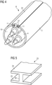
- figure 4 shows the ready-made submarine cable 6 'according to the invention in a second embodiment with a flexible H-shaped fastener tape 23, which in the separating slot 12 between the two longitudinal edges 11 of the cable protection tube 5 in particular over the entire length of the cable protection tube 5 is inserted in particular in a clamping manner and glued in there via an adhesive layer 27 .
- figure 5 shows the H-shaped fastener tape 23 after figure 4
- the dimensions of the two parallel legs 24, 25 and the intermediate web 26 depend on the diameter and the wall thickness of the cable protection tube 5, the thickness and Surface of the adhesive layer 27, ( 4 ) and the adhesive strength of the adhesive of the adhesive layer 27 ( 4 ) away.
- the fastening strip 23 is inserted into the separating slot 12 of the cable protection tube 5 in such a way that the two parallel legs 24 of the fastening strip 23 run in the circumferential direction of the cable protection tube 5 and are applied to the jacket of the cable protection tube 5 and that the intermediate web 26 of the closure band 23 runs in the radial direction of the cable protection tube 5 and is applied between the surfaces of the two longitudinal edges 11 of the cable protection tube 5, if necessary with a slight circumferential clamping force.
Description
Die Erfindung betrifft ein Verfahren und eine Vorrichtung zur Herstellung eines Seekabels (auch Offshore-Kabel genannt) sowie ein damit hergestelltes Seekabel, insbesondere zur Energie- und/oder Datenübertragung zwischen einer Windenergieanlage eines Offshore-Windparks auf See und/oder weiterer Windenergieanlagen des gleichen Offshore-Windparks und/oder anderer Offshore-Windparks auf See oder Onshore-Windparks auf dem Festland, ggfs. über elektrische Umspannwerke.The invention relates to a method and a device for producing a submarine cable (also called offshore cable) and a submarine cable produced therewith, in particular for energy and/or data transmission between a wind turbine of an offshore wind farm at sea and/or other wind turbines of the same offshore - Wind farms and/or other offshore wind farms at sea or onshore wind farms on the mainland, possibly via electrical substations.
Seekabel werden beim Stand der Technik innerhalb von Offshore-Windparks zwischen einzelnen Windenergieanlagen als Infield-Seekabel geringeren Durchmessers oder von Offshore-Windparks zum Festland als Export-Seekabel größeren Durchmessers mittels sogenannter "Kabelleger-Schiffe" auf und/oder im Meeresboden verlegt.In the prior art, submarine cables are laid on and/or in the seabed within offshore wind farms between individual wind turbines as infield submarine cables with a smaller diameter or from offshore wind farms to the mainland as export submarine cables with a larger diameter using so-called "cable laying ships".
Ein derartiges im radialen Querschnitt zylindrische Seekabel für Drehstrom oder Hochspannungs-Gleichstrom-Übertragung (HGÜ) besteht beim Stand der Technik aus einer Mehrzahl von Energieleitern insbesondere aus Kupfer und/oder einer Mehrzahl von Datenleitern insbesondere aus Kupfer oder Glas- oder Kunststofffasern, welche innerhalb einer rohrförmigen Kabel-Schutzhülle (Ummantelung) insbesondere aus flexiblem Kunststoff oder Metall aufgenommen und dort wasserdicht und vor mechanischer und chemischer Beschädigung geschützt eingebettet sind.In the prior art, such a submarine cable, which has a cylindrical radial cross section, for three-phase current or high-voltage direct current (HVDC) transmission consists of a plurality of energy conductors, in particular made of copper, and/or a plurality of data conductors, in particular made of copper or glass or plastic fibers, which are connected within a tubular cable protective sleeve (sheathing) recorded in particular made of flexible plastic or metal and embedded there waterproof and protected from mechanical and chemical damage.
Die Schichten der rohrförmigen Kabel-Schutzhülle können von radial außen nach radial innen wie folgt ausgebildet sein:
Polyethylen-Rohr (PET), biaxial-orientierte Polyesterfolie (boPET), verdrillte Stahlseile als rohrförmige Armierung, Aluminium-Rohr als Wasserbarriere, Polycarbonat-Rohr, Kupfer- oder Aluminium-Rohr, Vaseline.The layers of the tubular cable protective sleeve can be designed as follows from radially outside to radially inside:
Polyethylene pipe (PET), biaxially oriented polyester film (boPET), twisted steel cables as tubular reinforcement, Aluminum tube as a water barrier, polycarbonate tube, copper or aluminum tube, petroleum jelly.
Ein alternativer Aufbau der Schichten der rohrförmigen Kabel-Schutzhülle kann wie folgt ausgebildet sein: Polypropylen-Verseilung (PP) Bitumen-Schicht, Armierung, Bitumen-Schicht, Einbettschicht.An alternative structure of the layers of the tubular cable protection sheath can be designed as follows: polypropylene stranding (PP) bitumen layer, reinforcement, bitumen layer, embedding layer.
Weitere Aufbauten der Schichten der rohrförmigen Kabel-Schutzhülle können natürlich auch möglich sein, die allesamt von der vorliegenden Erfindung umfasst sein sollen.Other structures of the layers of the tubular cable protective sleeve can of course also be possible, all of which are intended to be encompassed by the present invention.
Die Energie- und Datenleiter des Seekabels liegen beispielsweise durch einen Eingieß- und/oder Eintauchvorgang geschützt eingebettet innerhalb der Vaseline-Schicht bzw. Einbettschicht.The energy and data conductors of the submarine cable are embedded within the Vaseline layer or embedding layer, for example protected by a casting and/or immersion process.
Nachteil ist, dass herkömmliche Offshore-Seekabel wegen ihrer im Vergleich zu Onshore-Kabeln sehr aufwändigen Armierung ein höheres Gewicht, größeren Außendurchmesser, größere Wandstärken und einen größeren min. Biegeradius aufweisen. Damit sind die Offshore-Seekabel kostenintensiver wegen der schwierigeren Handhabung, d.h. Herstellung, Lagerung, Transport und Verlegung auf/im Meeresboden.The disadvantage is that conventional offshore sea cables have a higher weight, larger outer diameter, greater wall thicknesses and a larger minimum bending radius due to their very complex armouring compared to onshore cables. This means that the offshore submarine cables are more expensive because of the more difficult handling, i.e. production, storage, transport and laying on/in the seabed.
Weiterer wesentlicher Nachteil ist, dass bei den Offshore-Kabeln im Vergleich zu Onshore-Kabeln lange Lieferfristen in Kauf genommen werden müssen, da es nur wenige (derzeit drei) hierauf spezialisierte Hersteller gibt.Another major disadvantage is that offshore cables have long delivery times compared to onshore cables, since there are only a few (currently three) manufacturers who specialize in this area.
Weitere Nachteile sind die relativ großen Übertragungsverluste auf Grund der Induktion zwischen den Energie- und Datenleitern und der Armierung, was wiederum eine größere Querschnittsfläche der Leiter erfordert, insbesondere bei Drehstromübertragung.Further disadvantages are the relatively large transmission losses due to induction between the power and data conductors and the armouring, which in turn requires a larger cross-sectional area of the conductors, particularly in the case of three-phase transmission.
Damit ist auch ein Anschließen der Offshore-Kabel innerhalb der Übergangsstücke zu anderen Offshore- oder Onshore-Kabeln oder Umspannwerken mit höheren Kosten verbunden.This also entails higher costs for connecting the offshore cables within the transition pieces to other offshore or onshore cables or substations.
In
In
In
In
In
In
In
In
In
Aufgabe der vorliegenden Erfindung ist es daher, ein Verfahren und eine Vorrichtung zur Herstellung eines gattungsgemäßen Seekabels derart weiter zu bilden, dass dieses einfacher und kostengünstiger in der Herstellung und ggfs. in der Verlegung in die See ist.The object of the present invention is therefore to further develop a method and a device for the production of a generic submarine cable in such a way that it is simpler and more cost-effective to produce and, if necessary, to lay in the sea.
Die gestellte Aufgabe wird durch das Verfahren zur Herstellung eines Seekabels gemäß des Patentanspruches 1, sowie durch die Vorrichtung zur Herstellung eines Seekabels gemäß des Patentanspruches 4, sowie durch das Seekabel gemäß des Patentanspruches 7 gelöst.The stated object is achieved by the method for producing a submarine cable according to patent claim 1 and by the device for producing a submarine cable according to
Ein gattungsgemäßes Seekabel beinhaltet eine Anzahl insbesondere elektrische und/oder optische Leiter, umfassend Energieleiter, insbesondere aus Kupfer, und/oder Datenleiter, insbesondere aus Kupfer oder Glas- oder Kunststofffasern, welche innerhalb eines insbesondere mindestens abschnittsweise flexiblen Kabel-Schutzrohres aus Kunststoff, aufgenommen und dort abgedichtet/wasserdicht vor mechanischer, physikalischer und chemischer Beschädigung geschützt eingebettet sind.A submarine cable of this type contains a number of, in particular, electrical and/or optical conductors, including energy conductors, in particular made of copper, and/or data conductors, in particular made of copper or glass or plastic fibers, which are accommodated within a protective cable tube made of plastic that is flexible at least in sections and embedded there in a sealed/watertight manner protected from mechanical, physical and chemical damage.
Das erfindungsgemäße Verfahren zur Herstellung eines derartigen Seekabels beinhaltet folgende Schritte:
- 1a) Bereitstellen der Leiter sowie des Kabel-Schutzrohrs und Fördern in einen gemeinsamen Montagebereich.
- 1b) Zusammenführen, bei insbesondere kontinuierlicher Förderung der Leiter und des Kabel-Schutzrohres in gleicher Förderrichtung, in einen gemeinsamen Zusammenführbereich.
Optionales insbesondere kontinuierliches Auftrennen des Mantels des Kabel-Schutzrohres in Längsrichtung in einem Öffnungsbereich, so dass sich ein Trennschlitz im Kabel-Schutzrohr bildet, der sich durch die gesamte Wandstärke des Mantels sowie über mindestens einen Teil der Länge des Kabel-Schutzrohres erstreckt. Alternativ kann ein in Längsrichtung verlaufender Trennschlitz im Mantel des Kabel-Schutzrohres bereits vorhanden sein, bevor das Kabel-Schutzrohr in den Montagebereich gefördert wird. Dabei kann dieser Trennschlitz vor dem Schritt 1a) außerhalb des Montagebereiches in den Mantel des Kabel-Schutzrohres durch den Hersteller des Kabel-Schutzrohres oder des fertig konfektionierten Seekabels eingebracht werden oder bereits bei der Herstellung integriert werden. - 1c) Öffnen, insbesondere Aufbiegen des in Längsrichtung des Kabel-Schutzrohres verlaufenden Trennschlitzes insbesondere radial, umfänglich, in Querschnittsrichtung, quer oder schräg im Winkel zur Längserstreckung des geöffneten Trennschlitzes im Öffnungsbereich, mindestens soweit, so dass sich eine Einführöffnung des geöffneten Trennschlitzes für die Leiter bildet.
- 1d) Offenhalten des geöffneten Trennschlitzes in einem Offenhaltebereich.
- 1e) Insbesondere kontinuierliches gemeinsames, teilweise gemeinsames oder zeitliches hintereinander Einführen der Leiter in das Kabel-Schutzrohr durch die Einführöffnung des geöffneten Trennschlitzes in einem Einführbereich.
- 1f) Lösen des Offenhaltens des geöffneten Trennschlitzes in einem Schließbereich, so dass sich stromabwärts zwei Längskanten des Trennschlitzes überlappen und so sich in einem Überlappungsbereich zwei überlappende streifenförmige Mantelwinkelbereiche bilden und dort mindestens die doppelte Mantelwandstärke des Kabel-Schutzrohres bilden.
- 1a) Providing the conductors and the cable protection tube and conveying them to a common assembly area.
- 1b) merging, in particular with continuous conveyance of the conductors and the cable protection tube in the same conveying direction, into a common merging area.
Optional, particularly continuous, slitting of the sheath of the cable protection tube in the longitudinal direction in an opening area, so that a separating slot is formed in the cable protection tube, which extends through the entire wall thickness of the sheath and over at least part of the length of the cable protection tube. Alternatively, a separating slot running in the longitudinal direction can already be present in the casing of the cable protection pipe before the cable protection pipe is conveyed into the assembly area. This separating slit can be made in the jacket of the cable protection tube outside the assembly area before step 1a) by the manufacturer of the cable protection tube or the ready-made submarine cable or it can already be integrated during production. - 1c) Opening, in particular bending open, the separating slot running in the longitudinal direction of the cable protection tube, in particular radially, circumferentially, in the cross-sectional direction, transversely or obliquely at an angle to the longitudinal extension of the opened separating slot in the opening area, at least to such an extent that an insertion opening of the opened separating slot for the conductors is located forms.
- 1d) keeping open the opened separating slot in a keeping-open area.
- 1e) In particular, the conductors are inserted continuously together, partially together or sequentially into the cable protection tube through the insertion opening of the opened separating slot in an insertion area.
- 1f) releasing the holding open of the opened separation slot in a closing area, so that downstream two longitudinal edges of the separating slit overlap and thus form two overlapping, strip-shaped casing angle areas in an overlapping area and there form at least twice the casing wall thickness of the cable protection pipe.
Schließen des geöffneten Trennschlitzes insbesondere durch Überlappen bzw. Übereinanderschlagen in einem Überlappungsbereich von Mantelwinkelstreifen des Kabel-Schutzrohres auf beiden Seiten des Trennschlitzes im Schließbereich, insbesondere mittels seitlicher schräger Führungsrollen. Alternativ kann auch ein Schließen des geöffneten Trennschlitzes derart erfolgen, dass beide Längskanten des Trennschlitzes Stoß-an-Stoß liegen und ggfs. miteinander fluchten und ggfs. sich berühren. Alternativ kann auch ein Schließen des geöffneten Trennschlitzes derart erfolgen, dass ein flexibles Verschlussband zwischen den zwei Längskanten des Trennschlitzes insbesondere klemmend dort aufgenommen wird. Auch beliebige Kombinationen der oben erwähnten Varianten sind sequenziell hintereinander möglich. Zeitlich vor oder während Schritt 1e oder zeitlich während oder nach Schritt 1f oder zeitlich zwischen Schritt 1e und Schritt 1f wird eine abdichtende/wasserdichte Einbettschicht/Vergussmasse in den Zwischenraum zwischen das Kabel-Schutzrohr und die darin befindlichen Leiter eingefüllt.Closing of the opened separating slot, in particular by overlapping or overlapping one another in an overlapping area of casing angle strips of the cable protection tube on both sides of the separating slot in the closing area, in particular by means of lateral, inclined guide rollers. Alternatively, the opened separating slit can also be closed in such a way that both longitudinal edges of the separating slit lie abutting and, if necessary, are aligned with one another and if necessary touch one another. Alternatively, the opened separating slit can also be closed in such a way that a flexible fastening strip is accommodated there between the two longitudinal edges of the separating slit, in particular in a clamped manner. Any combinations of the variants mentioned above are also possible sequentially one after the other. Before or during step 1e or during or after step 1f or between step 1e and step 1f, a sealing/waterproof embedding layer/casting compound is filled into the space between the cable protection tube and the conductors located therein.
Die erfindungsgemäße Vorrichtung zur Herstellung eines Seekabels beinhaltet gemäß Patentanspruch 4 entsprechende Einrichtungen zur Ausübung der zuvor genannten Verfahrenschritte. Das erfindungsgemäße Seekabel gemäß Patentanspruch 7 entspricht einem gattungsgemäßen Seekabel und unterscheidet sich dadurch, dass sich zwei in einem Überlappungsbereich befindliche bevorzugt in Längsrichtung verlaufende Mantelwinkelstreifen des Kabel-Schutzrohres aus Kunststoff überlappen oder die zwei Längskanten des Trennschlitzes aneinanderstoßen, oder die zwei Längskanten des Trennschlitzes zwischen sich ein Verschlussband insbesondere klemmend aufnehmen. Die jeweiligen Verbindungsbereiche der zuvor beschriebenen drei Varianten sind insbesondere abgedichtet/wasserdicht vor mechanischer, physikalischer und chemischer Beschädigung geschützt und/oder insbesondere unlösbar miteinander verbunden.According to
Alternativ kann daher das Kabel-Schutzrohr mit einem z.B. H-förmigen Verschlussband verschlossen werden, wobei Mantelwinkelstreifen des Kabel-Schutzrohrs in Nuten des H-förmigen Verschlussbandes eingreifen und den Trennschlitz verschließen. Das H-förmige Verschlussband kann hierbei aus Segmenten bestehen oder als Laufware genutzt und kontinuierlich eingefügt werden. Eine Einbringung von einem Klebstoff, Adhäsiv oder anderem Fügematerial wie beispielsweise Silikon ist hierbei auch denkbar. In einer weiteren alternativen Anordnung kann das Kabelschutzrohr durch einen Schweißvorgang geschlossen und versiegelt werden.Alternatively, the cable protection tube can therefore be closed with an H-shaped closure strip, for example, with the angle strips on the cable protection tube engaging in grooves in the H-shaped closure strip and closing the separating slot. The H-shaped fastener tape can consist of segments or be used as running goods and inserted continuously. The introduction of an adhesive, adhesive or other joining material such as silicone is also conceivable here. In a further alternative arrangement, the conduit may be closed and sealed by a welding operation.
Das erfindungsgemäße Seekabel umfasst auch eine abdichtende/wasserdichte Einbettschicht/Vergussmasse in dem Zwischenraum zwischen dem Kabel-Schutzrohr und den darin befindlichen Leitern.The submarine cable of the present invention also includes a sealing/waterproof potting/potting compound in the space between the cable conduit and the conductors therein.
Die Leiter des erfindungsgemäßen Seekabels sind insbesondere durch eine Aluminium-Ummantelung zwischen einer äußeren Gummiummantelung und dem Leiter vor Wasser geschützt. Ferner erlaubt ein Eindringen von Wasser in das Kabelschutzrohr eine besonders gute Kühlung der Leiterkabel, was weniger Widerstandsverlust, sowie mehr Leistung auf dem Leiterkabel ermöglicht.The conductors of the submarine cable according to the invention are protected from water in particular by an aluminum sheathing between an outer rubber sheathing and the conductor. Furthermore, penetration of water into the cable protection tube allows for particularly good cooling of the conductor cable, which enables less resistance loss and more power on the conductor cable.
Dieses erfindungsgemäße Offshore-Kabel und dessen Herstellverfahren sind deshalb vorteilhaft, da diese sehr kostengünstig sind. Damit können Standard-Komponenten direkt auf einem Installations-Schiff (Kabelleger-Schiff) zu dem erfindungsgemäßen Offshore-Kabel zusammengeführt werden, wohingegen der Stand der Technik eine mühsame Installation in einer Fabrik verlangt, mit Problemen bei Lagerung, Transport und Bereitstellung zum Verlegen auf dem Schiff. Weiterhin gibt es viele Hersteller der Standard-Komponenten der Erfindung, wohingegen es nur wenig Zulieferer von Offshore-Kabeln des Standes der Technik gibt, die zudem teuer sind. Weitere Vorteile der erfindungsgemäßen Offshore-Kabel sind, dass kleinere Kabelverleger-Schiffe oder gar einfache Schiffe mit genügend Raum auf dem Schiffsdeck eingesetzt werden können, so dass die Verlegung der Offshore-Kabel noch einmal kostengünstiger wird. Eine sofortige (just in time) Lieferung aller Kabel ist möglich, da die Einzelkabel und die Kabelschutzrohre (insbesondere aus HDPE-Kunststoff = High Density Polyethylen) Standard-Komponenten im Handel sind. Weitere, besonders vorteilhafte Ausgestaltungen und Weiterbildungen der Erfindung ergeben sich aus den abhängigen Ansprüchen sowie der nachfolgenden Beschreibung. Die abhängigen Ansprüche sowie die nachfolgende Beschreibung enthalten besonders vorteilhafte Weiterbildungen und Ausgestaltungen der Erfindung, wobei insbesondere auch die Ansprüche einer Kategorie analog zu den abhängigen Ansprüchen einer anderen Anspruchskategorie weitergebildet sein können. Ebenso können Merkmale verschiedener Ausführungsvarianten kombiniert werden.This offshore cable according to the invention and its manufacturing method are advantageous because they are very inexpensive. This means that standard components can be brought together directly on an installation ship (cable laying ship) to form the offshore cable according to the invention, whereas the prior art requires a tedious installation in of a factory, with problems in storage, transport and preparation for laying on the ship. Furthermore, there are many manufacturers of the standard components of the invention, while there are few suppliers of prior art offshore cables, which are also expensive. Further advantages of the offshore cable according to the invention are that smaller cable-laying ships or even simple ships with sufficient space on the ship's deck can be used, so that the laying of the offshore cable becomes even more cost-effective. Immediate (just-in-time) delivery of all cables is possible because the individual cables and the cable protection tubes (in particular made of HDPE plastic = high-density polyethylene) are standard components on the market. Further, particularly advantageous configurations and developments of the invention result from the dependent claims and the following description. The dependent claims and the following description contain particularly advantageous developments and refinements of the invention, in which case the claims in one category can also be developed analogously to the dependent claims in another claim category. Likewise, features of different design variants can be combined.
Das optionale Auftrennen des Kabel-Schutzrohres erfolgt durch mechanisches und/oder physikalisches und/oder chemisches Trennen. Insbesondere erfolgt das Auftrennen durch spanloses Trennen insbesondere mittels Messer, Klinge, Schere, die ggfs. elektrisch beheizbar sind. Alternativ kann das Auftrennen durch spanabtragendes Trennen insbesondere mittels Stanzen oder Fräser und/oder durch Flüssigkeits- oder Partikelstrahlen insbesondere mittels Wasserstrahl oder Sandstrahl erfolgen. Am einfachsten und kostengünstigen ist aber ein Auftrennen mittels Messer oder Klinge, welche auf einer Vorrichtung fest stehen und sich das Kabel-Schutzrohr relativ dazu in Förderrichtung bewegt. Die Fördergeschwindigkeit wird dabei auf das Material (z.B. HDPE-Kunststoff) des Kabel-Schutzrohrs abgestimmt.The optional separation of the cable protection tube is carried out by mechanical and/or physical and/or chemical separation. In particular, the separating takes place by non-cutting separating, in particular by means of a knife, blade, scissors, which can be electrically heated if necessary. Alternatively, the separation can take place by means of chip-removing separation, in particular by means of punches or milling cutters and/or by liquid or particle jets, in particular by means of a water jet or sand blast. However, the simplest and most cost-effective way is to cut using a knife or blade, which is fixed to a device and the cable protection tube moves relative to it in the conveying direction. the The conveying speed is matched to the material (e.g. HDPE plastic) of the cable protection tube.
Insbesondere erfolgt das Aufbiegen des Trennschlitzes mittels Kraftwirkung mindestens eines Keiles, der auch für das Offenhaltendes geöffneten Trennschlitzes in Schritt 1e) sorgen kann, zusätzlich oder alternativ zu mindestens einer Führungsrolle. Die Keile und Führungsrollen greifen dabei über die Einführöffnung in den Innenraum des geöffneten Kabel-Schutzrohrs ein und lassen die Kanten des geöffneten Mantels des geöffneten Kabel-Schutzrohrs während der Förderung des Kabel-Schutzrohrs auf sich aufgleiten.In particular, the separating slot is bent open by means of the force of at least one wedge, which can also ensure that the opened separating slot is kept open in step 1e), in addition or as an alternative to at least one guide roller. The wedges and guide rollers reach into the interior of the opened cable protection tube via the insertion opening and allow the edges of the opened casing of the opened cable protection tube to slide onto them while the cable protection tube is being conveyed.
Das Einführen aller elektrischer und/oder optischer Leiter in das Kabel-Schutzrohr in Schritt 1e) erfolgt bevorzugt gemeinsam, wobei alle Leiter sowie das Kabel-Schutzrohr etwa gleiche Fördergeschwindigkeit aufweisen. Damit ist eine sehr schnelle Einbringung der Leiter in das Kabel-Schutzrohr möglich. In einer anderen Ausführungsform können die Leiter aber auch zeitversetzt zueinander in das Kabel-Schutzrohr eingebracht werden, falls z.B. die Einführöffnung nicht groß genug gewählt werden kann, z.B. wegen einer zu geringen Elastizität des Materials des Kabel-Schutzrohrs. Optional wird nach dem Einbringen der Leiter in das Kabel-Schutzrohr, ein im Querschnitt I-, L-, Z-, T-, oder H-förmiges flexibles Verschlussband zumindest in den Trennschlitz des Kabel-Schutzrohrs eingeführt.The insertion of all electrical and/or optical conductors into the protective cable tube in step 1e) is preferably carried out together, with all conductors and the protective cable tube having approximately the same conveying speed. This enables the conductors to be inserted very quickly into the cable protection tube. In another embodiment, the conductors can also be inserted into the protective cable tube at different times if, for example, the insertion opening cannot be selected large enough, e.g. because the material of the protective cable tube is not sufficiently elastic. Optionally, after inserting the conductors into the cable protection tube, a flexible fastening tape with an I, L, Z, T or H cross section is inserted at least into the separating slot of the cable protection tube.
Das Schließen des geöffneten Trennschlitzes erfolgt zunächst durch die Eigenelastizität des Kabel-Schutzrohrs, wenn die Kraftwirkung der Einrichtung zum Offenhalten (Keil und/oder innere Führungsrollen) entfällt, auf Grund der fortschreitenden Förderung des Kabel-Schutzrohrs. Diese Eigenelastizität des Kabel-Schutzrohrs bewirkt jedoch in der Regel kein vollkommenes Schließen oder lediglich ein Stoß-an-Stoß-Schließen des Trennschlitzes des Kabel-Schutzrohrs, ggfs. mit dazwischen eingeklemmtem elastischem Verschlussband. Um einen noch weiter verbesserten Schutz der darin aufgenommenen Leiter zu erreichen, kann vorzugsweise ein aktives Übereinanderschlagen der beiden Längskanten des Trennschlitzes des Kabel-Schutzrohres übereinander erfolgen, insbesondere mittels seitlicher schräger Führungsrollen. Durch diese seitlichen schrägen Führungsrollen werden ohnehin notwendige seitliche Führungsrollen an dieser Stelle ersetzt, so dass die Vorrichtung kostengünstiger wird. Dieses Übereinanderschlagen der beiden Längskanten des Trennschlitzes des Kabel-Schutzrohres kann auch durch andere Einrichtungen erfolgen, so z.B. durch Krafteinwirkung von Stößeln oder Exzenternocken auf einer oder auf beiden Seiten des Kabel-Schutzrohres, wobei dann aber Gegenlager nötig sind, z.B. seitliche Führungsrollen mit vertikaler Drehachse. Diese seitlichen Gegenlager für die Stößel oder Exzenternocken können aber auch entfallen, falls diese von oben her auf die beiden Längskanten des Trennschlitzes des Kabel-Schutzrohres wirken.The opening of the separating slot is initially closed by the inherent elasticity of the cable protection tube when the force exerted by the device to keep it open (wedge and/or inner guide rollers) is no longer available due to the progressive conveyance of the cable protection tube. However, this inherent elasticity of the cable protection tube does not usually cause a complete closure or only a butt-to-butt closure of the separating slot of the cable protection tube, possibly with something clamped in between elastic closure strap. For an even better one In order to protect the conductors accommodated therein, the two longitudinal edges of the separating slot of the cable protection tube can preferably be actively folded over one another, in particular by means of laterally inclined guide rollers. Lateral guide rollers that are necessary in any case are replaced at this point by these lateral inclined guide rollers, so that the device becomes more cost-effective. This overlapping of the two longitudinal edges of the separating slot of the cable protection tube can also be achieved by other means, e.g. by the application of force from rams or eccentric cams on one or both sides of the cable protection tube, but counter bearings are then necessary, e.g. lateral guide rollers with a vertical axis of rotation . However, these lateral counter bearings for the plungers or eccentric cams can also be omitted if they act on the two longitudinal edges of the separating slot of the cable protection tube from above.
Zeitlich vor oder während Schritt 1e) oder zeitlich während oder nach Schritt 1f) oder zeitlich zwischen Schritt 1e) und Schritt 1f) wird eine herkömmliche abdichtende/wasserdichte Einbettschicht/Vergussmasse, insbesondere Bitumen und/oder Kunststoff, in den Zwischenraum zwischen das Kabel-Schutzrohr und die darin befindlichen Leitern eingefüllt.Before or during step 1e) or during or after step 1f) or between step 1e) and step 1f), a conventional sealing/waterproof embedding layer/potting compound, in particular bitumen and/or plastic, is placed in the space between the cable protection pipe and filled the ladders inside.
Diese abdichtende Einbettschicht/Vergussmasse kann auch im Überlappungsbereich in den Zwischenraum zwischen den beiden sich überlappenden Mantelwinkelstreifen des Kabel-Schutzrohres eingefüllt werden, welche somit abdichtend/wasserdicht unlösbar miteinander verbunden werden. Alternativ können die beiden Mantelwinkelstreifen auch mittels anderer Verbindungsarten miteinander abdichtend verbunden werden, wie z.B. durch Verkleben, Vulkanisieren, Thermisches Verbinden, Verschweißen, Verlöten etc..This sealing embedding layer/casting compound can also be filled in the overlapping area in the space between the two overlapping angle strips of the cable protection pipe, which are thus connected to one another in a sealing/watertight inseparable manner. Alternatively, the two casing angle strips can also be connected to one another in a sealing manner using other types of connection, such as by gluing, vulcanizing, thermally connecting, welding, soldering, etc.
In einer alternativen Ausführungsform der vorliegenden Erfindung sind die beiden Längskanten des Trennschlitzes des Kabel-Schutzrohres, in einer stirnseitig zueinander fluchtenden, sich berührenden oder berührungslosen, Stoß-an-Stoß-Lage der beiden einander benachbarten Längskanten, durch eine Verschweißung und/oder Verklebung, insbesondere in Längsrichtung, miteinander verbunden und durch diese Verschweißung und/oder Verklebung vorzugsweise auch gegen Wasserdruck in der Verlegetiefe der See abgedichtet. Bevorzugt wird daher, dass eine durchgehende Verklebung oder Verschweißung des Kabel-Schutzrohres in Längsrichtung erfolgt.In an alternative embodiment of the present invention, the two longitudinal edges of the separating slot of the cable protection tube are in a face-to-face relation to one another aligned, touching or non-contact, butt-to-butt position of the two adjacent longitudinal edges, connected to one another by welding and/or gluing, in particular in the longitudinal direction, and by this welding and/or gluing preferably also against water pressure at the laying depth of the lake sealed. It is therefore preferred that the cable protection tube is continuously bonded or welded in the longitudinal direction.
In einer alternativen Ausführungsform der vorliegenden Erfindung sind die beiden Längskanten des Trennschlitzes des Kabel-Schutzrohres, in einer stirnseitig zueinander fluchtenden berührungslosen Stoß-an-Stoß-Lage der beiden einander benachbarten Längskanten, über ein in den Trennschlitz eingeführtes, im Querschnitt insbesondere I-, L-, Z-, T-, oder H-förmiges, insbesondere flexibles, Verschlussband miteinander verbunden und durch dieses Verschlussband vorzugsweise auch gegen Wasserdruck in der Verlegetiefe der See abgedichtet. Hierzu wird das in den Trennschlitz eingeführte Verschlussband mit dem Kabel-Schutzrohr bevorzugt verklebt und/oder verschweißt. Das Verkleben muss nicht zwingend über den gesamten Querschnitt des Verschlussbandes verlaufen, sondern kann auch nur Abschnittsweise erfolgen. Bevorzugt wird aber, dass eine durchgehende Verklebung oder Verschweißung des Verschlussbandes in Längsrichtung des Verschlussbandes bzw. des Kabel-Schutzrohres erfolgt. Das Verschlussband ist hierbei flexibel ausgebildet und insbesondere aus einem Kunststoffmaterial, bevorzugt aus dem gleichen Kunststoff, wie das Kabel-Schutzrohr, z.B. aus HDPE-Kunststoff.In an alternative embodiment of the present invention, the two longitudinal edges of the separating slot of the cable protection tube, in a contact-free butt-to-butt position of the two adjacent longitudinal edges, which are aligned at the front side, are connected via a cross-section in particular I-, L-, Z-, T-, or H-shaped, in particular flexible, fastener tape connected to one another and preferably also sealed against water pressure at the laying depth of the sea by this fastener tape. For this purpose, the sealing tape introduced into the separating slot is preferably glued and/or welded to the cable protection tube. The gluing does not necessarily have to run over the entire cross section of the fastening tape, but can also only take place in sections. However, it is preferred that the sealing strip is continuously bonded or welded in the longitudinal direction of the sealing strip or the protective cable tube. In this case, the closure band is flexible and in particular made of a plastic material, preferably made of the same plastic as the cable protective tube, e.g. made of HDPE plastic.
Die erfindungsgemäße Vorrichtung beinhaltet als Bereitstelleinrichtung zum Bereitstellen der Leiter und des Kabel-Schutzrohres vorzugsweise herkömmliche Aufwickelhaspeln bzw. Kabeltrommeln mit liegender oder stehender Achse. Hierbei können auch sehr lange Seekabel einfach und kostengünstig hergestellt werden, indem die Leiter und KabelSchutzrohre jeweils auf einer zugeordneten Aufwickelhaspel bzw. Kabeltrommel aufgewickelt sind und auf das Kabellegerschiff transportiert werden, um dann während des Verlegevorganges abgewickelt, konfektioniert und in der See verlegt zu werden. Somit ist es möglich, dass seriell hintereinander folgend mehrere kürzere Leiter in ein gemeinsames Kabel-Schutzrohr verlegt und über elektrisch und/oder optisch leitende und ggfs. abdichtende Leiter-Verbindungen miteinander verbunden werden. Die Leiter sind hierbei insbesondere an ihren Endstücken mit Aluminium verschweißt und bilden somit eine durchgängige leitende Verbindung. Die Schweißpunkte sind mit Kunststoff versiegelt. Ferner sind die Schweißverbindungen in Längsrichtung versetzt angeordnet um eine zu große Verdickung an einer Stelle zu vermeiden. Eine Leiter-Verbindung hat dabei einen z.B. doppelt so großen Außendurchmesser als ein Leiter selbst. Deswegen ist es vorteilhaft, dass die Leiter-Verbindungen parallel verlegter Leiter zueinander in Längsrichtung versetzt im Kabel-Schutzrohr zu liegen kommen, da hiermit das Kabel-Schutzrohr relativ klein im Durchmesser gewählt werden kann, weil sich die Mehrzahl von Leiter-Verbindungen paralleler Leiter auf diese Art und Weise gegenseitig nicht behindern können, wenn das Kabel-Schutzrohr sich schließt bzw. geschlossen wird. Dadurch können viele kleinere Längen von Leitern bzw. von Kabel-Schutzrohren zu einem sehr langen (hunderte oder tausende von Kilometern) Seekabel zusammen gefügt und in die See verlegt werden. Damit können auch die Aufwickelhaspeln bzw. Kabeltrommeln relativ klein dimensioniert werden und stattdessen eine größere Anzahl gewählt werden, um die zu verlegende Strecke mit einem Seekabel zu überbrücken. Dies führt zu geringeren Transportkosten, da herkömmliche Transportfahrzeuge eingesetzt werden können und keine Spezialfahrzeuge nötig sind.The device according to the invention preferably contains conventional winding reels or cable drums with a horizontal or vertical axis as the provision device for preparing the conductors and the protective cable tube. Very long submarine cables can also be manufactured easily and inexpensively by using the conductors and cable protection tubes are each wound on an associated take-up reel or cable drum and are transported to the cable laying ship, in order to then be unwound during the laying process, assembled and laid in the sea. It is thus possible for several shorter conductors to be laid in series in a common cable protection tube and connected to one another via electrically and/or optically conductive and possibly sealing conductor connections. The conductors are welded to aluminum, particularly at their end pieces, and thus form a continuous conductive connection. The welding points are sealed with plastic. Furthermore, the welded joints are offset in the longitudinal direction in order to avoid excessive thickening at one point. A conductor connection has, for example, twice the outer diameter of the conductor itself. It is therefore advantageous for the conductor connections of conductors laid parallel to each other to be offset in the longitudinal direction in the cable protection tube, as this makes the cable protection tube relatively small can be chosen in diameter, because the plurality of conductor connections of parallel conductors cannot impede each other in this way when the cable protection tube closes or is closed. As a result, many smaller lengths of conductors or cable protection tubes can be joined together to form a very long (hundreds or thousands of kilometers) submarine cable and laid in the sea. This means that the take-up reels or cable drums can also be made relatively small and instead a larger number can be selected in order to bridge the route to be laid with a submarine cable. This leads to lower transport costs, since conventional transport vehicles can be used and no special vehicles are required.
Als Förder- und Zusammenführeinrichtung zum Fördern und Zusammenführen der Leiter und des Kabel-Schutzrohres sowie des fertig konfektionierten Seekabels, können auf einem leiter- oder kettenförmigen Grundrahmen aktiv antreibbare Antriebe insbesondere in Form von Förderbändern und passiv antreibbare/mitlaufende seitliche und obere Führungsrollen insbesondere in Form von stehenden oder liegenden Zylindern vorhanden sein. Die stehenden Zylinder der Führungsrollen können in ihrem mittleren Mantelbereich konkave Ausnehmungen, in welche dann das Kabel-Schutzrohr eingreifen und somit seitlich geführt und/oder angetrieben werden kann. Die seitlichen Führungsrollen sind hierbei insbesondere paarweise auf dem Grundrahmen angebracht, damit das Kabel-Schutzrohr links und rechts der Förderrichtung gleichmäßig geführt werden kann. Hingegen haben die oberen Führungsrollen als Gegenlager die aktiv antreibbaren Förderbänder.As a conveying and merging device for conveying and merging the conductors and the cable protection tube and the ready-made submarine cable, on a Ladder or chain-shaped base frame, actively drivable drives, in particular in the form of conveyor belts, and passively drivable/following lateral and upper guide rollers, in particular in the form of standing or lying cylinders. The stationary cylinders of the guide rollers can have concave recesses in their central shell area, in which the cable protection tube can then engage and thus be guided and/or driven laterally. The lateral guide rollers are mounted in pairs on the base frame, so that the cable protection tube can be guided evenly to the left and right of the conveying direction. On the other hand, the upper guide rollers have the actively drivable conveyor belts as a counter bearing.
Natürlich kann auch jede der seitlichen und/oder oberen Führungsrollen ebenfalls aktiv antreibar sein. Auch können die aktiv antreibbaren Förderbänder entfallen und stattdessen untere Führungsrollen vorhanden sein, ähnlich der oberen Führungsrollen, wobei der aktive Antrieb dann z.B. außerhalb des Rahmens der Vorrichtung angeordnet wäre. Auch können sämtliche passiven mitgetriebenen Führungsrollen auch ortsfest ausgeführt sein und lediglich einen geringen Reibkoeffizienten mindestens auf der dem Kabel-Schutzrohr zugewandten Oberfläche aufweisen, so dass das Kabel-Schutzrohr entlang diesen glatten Oberflächen der z.B. auf dem Grundrahmen feststehenden Führungsrollen geführt gleiten können.Of course, each of the lateral and/or upper guide rollers can also be actively driven. The actively drivable conveyor belts can also be omitted and lower guide rollers can be present instead, similar to the upper guide rollers, in which case the active drive would then be arranged, for example, outside the frame of the device. All passive, co-driven guide rollers can also be stationary and only have a low coefficient of friction, at least on the surface facing the cable protection pipe, so that the cable protection pipe can slide along these smooth surfaces of the guide rollers, which are fixed on the base frame, for example.
Die optionale Auftrenneinrichtung zum Auftrennen des Mantels des Kabel-Schutzrohres beinhalten eine Anzahl insbesondere am Grundrahmen fest stehender Messer, Klingen, oder beweglicher Scheren, Stanzen, Fräser, Wasserstrahl- oder Sandstrahleinrichtungen. Feststehende Messer und Klingen sind aber zum Auftrennen eines Kabel-Schutzrohres aus Kunststoff besonders gut geeignet und zudem sehr preisgünstig.The optional separating device for separating the jacket of the cable protection pipe includes a number of fixed knives, blades, or movable shears, punches, milling cutters, water jet or sand blasting devices, in particular on the base frame. However, fixed knives and blades are particularly well suited for cutting through a plastic cable protection tube and are also very inexpensive.
Die Öffnungseinrichtung zum Öffnen, insbesondere Aufbiegen, des Trennschlitzes beinhalten mindestens einen insbesondere fest stehenden Keil, der ggfs. die Einrichtung zum Auftrennen des Mantels des Kabel-Schutzrohres trägt. Alternativ zum Keil kann auch ein Stift, eine Nocke, oder eine feststehende oder passiv drehbare oder aktiv sich drehende Rolle oder Walze eingesetzt werden, ähnlich den seitlichen oder oberen Führungsrollen.The opening device for opening, in particular bending open, the separating slot contain at least one in particular Fixed wedge, which may carry the device for separating the jacket of the cable protection tube. As an alternative to the wedge, a pin, a cam, or a stationary or passively rotating or actively rotating roller or roller can also be used, similar to the side or top guide rollers.
Die Offenhalteeinrichtung zum Offenhalten des geöffneten Trennschlitzes beinhalten bevorzugt eine Anzahl insbesondere fest stehender Keile und/oder eine Anzahl insbesondere ortsfester aktiv und/oder passiv antreibbare Führungsrollen, ähnlich den seitlichen oder oberen Führungsrollen. Statt der Keile können auch Führungsrollen, ähnlich den seitlichen oder oberen Führungsrollen verwendet werden.The keeping-open device for keeping the opened separating slot open preferably contain a number of, in particular, fixed wedges and/or a number of, in particular, stationary, actively and/or passively drivable guide rollers, similar to the lateral or upper guide rollers. Guide rollers, similar to the lateral or top guide rollers, can also be used instead of the wedges.
Die Schließeinrichtung zum Schließen des geöffneten Trennschlitzes kann eine Anzahl insbesondere ortsfester aktiv und/oder passiv antreibbare schräge Führungsrollen beinhalten, die auch durch Stifte oder Nocken etc. ersetzt werden können.The closing device for closing the opened separating slot can contain a number of, in particular, stationary, actively and/or passively drivable inclined guide rollers, which can also be replaced by pins or cams, etc.
Das erfindungsgemäße Seekabel kennzeichnet sich in einer bevorzugten Variante dadurch aus, dass entweder die zwei sich überlappenden in Längsrichtung verlaufenden Mantelwinkelstreifen des Kabel-Schutzrohres aufeinander aufliegen und/oder der radiale Zwischenraum zwischen den zwei sich überlappenden in Längsrichtung verlaufenden Mantelwinkelstreifen des Kabel-Schutzrohres mit der abdichtenden/wasserdichten Vergussmasse gefüllt ist.In a preferred variant, the submarine cable according to the invention is characterized in that either the two overlapping longitudinally extending casing angle strips of the cable protection pipe rest on one another and/or the radial gap between the two overlapping longitudinally extending casing angle strips of the cable protection pipe with the sealing / waterproof potting compound is filled.
Bevorzugt hat das Seekabel folgende Maße: Der Durchmesser des Kabel-Schutzrohres beträgt nach dem Schritt 1f) zwischen 50% und 99% insbesondere zwischen 60% und 90% ganz besonders zwischen 70% und 80% des ursprünglichen Durchmessers des Kabel-Schutzrohres vor/im Schritt 1a). Gleichzeitig oder alternativ beträgt der überlappende Mantelwinkelbereich des Kabel-Schutzrohres zwischen 1° und 180° insbesondere zwischen 10° und 90° ganz besonders zwischen 30° und 45°.The submarine cable preferably has the following dimensions: after step 1f), the diameter of the cable protection pipe is between 50% and 99%, in particular between 60% and 90%, particularly between 70% and 80% of the original diameter of the cable protection pipe before/inside Step 1a). At the same time or alternatively, the overlapping jacket angle range of the cable protection tube is between 1° and 180°, in particular between 10° and 90°, particularly between 30° and 45°.
Für die weitere Ausführungsform, bei welcher der Trennschlitz des Kabel-Schutzrohrs Stoß-an-Stoß geschlossen wird, liegt der Durchmesser des Kabel-Schutzrohres nach dem Schritt 1f) natürlich bei ca. 100% des Durchmessers des Kabel-Schutzrohres vor/im Schritt 1a), oder etwas darüber oder etwas darunter.For the further embodiment, in which the separating slot of the cable protection tube is closed end-to-end, the diameter of the cable protection tube after step 1f) is of course approximately 100% of the diameter of the cable protection tube before/in step 1a ), or something above or something below.
Für die weitere Ausführungsform, bei welcher der Trennschlitz des Kabel-Schutzrohrs über ein dort eingefügtes Verbindungsband geschlossen wird, liegt der Durchmesser des Kabel-Schutzrohres nach dem Schritt 1f) natürlich bei über 100% des Durchmessers des Kabel-Schutzrohres vor/im Schritt 1a), z.B. zwischen 101% und 110%, je nach Querschnitt des Verbindungsbandes.For the further embodiment, in which the separating slot of the cable protection pipe is closed via a connecting strap inserted there, the diameter of the cable protection pipe after step 1f) is of course more than 100% of the diameter of the cable protection pipe before/in step 1a) , eg between 101% and 110%, depending on the cross-section of the connecting strap.
Insbesondere ist das Kabel-Schutzrohr aus hochdichtem Polyethylen (HDPE) insbesondere mit Dichte größer gleich 0,94 g/cm3 und kleiner gleich 0,97 g/cm3 gebildet, was gut verarbeitbar, stabil, flexibel und dennoch kostengünstig ist. Andere Kunststoffmaterialien sind aber ebenso möglich.In particular, the cable protection tube is made of high-density polyethylene (HDPE), in particular with a density of greater than or equal to 0.94 g/cm 3 and less than or equal to 0.97 g/cm 3 , which is easy to process, stable, flexible and yet inexpensive. However, other plastic materials are also possible.
Besonders vorteilhaft ist, wenn das erfindungsgemäße Verfahren und/oder die erfindungsgemäße Vorrichtung und/oder das fertig konfektionierte Seekabel sich auf einem Kabelverleger-Schiff befinden, so dass damit z.B. die Leiter und das Kabel-Schutzrohr einzeln vorgehalten werden können und das fertig konfektionierte Seekabel ohne Zwischenlagerung, ggfs. unter einer Zugentlastungsreserve, auf dem Kabelverleger-Schiff, in die See bzw. auf dem bzw. im Meeresboden verlegt werden kann.It is particularly advantageous if the method according to the invention and/or the device according to the invention and/or the ready-made submarine cable are located on a cable-laying ship, so that, for example, the conductors and the cable protective tube can be kept available individually and the ready-made submarine cable without Intermediate storage, possibly under a strain relief reserve, on the cable-laying ship, can be laid in the sea or on or in the seabed.
Die Erfindung wird im Folgenden unter Hinweis auf die beigefügten Figuren anhand von Ausführungsbeispielen noch einmal näher erläutert. Dabei sind in den verschiedenen Figuren gleiche Komponenten mit identischen Bezugsziffern versehen. Die Figuren sind in der Regel nicht maßstäblich.The invention is explained in more detail below with reference to the attached figures using exemplary embodiments. The same components are provided with identical reference numbers in the various figures. The figures are generally not to scale.
Es zeigen:
-
Figur 1 eine schematische perspektivische Gesamtdarstellung der erfindungsgemäßen Vorrichtung zur Herstellung des erfindungsgemäßen Seekabels; -
Figur 2 -
Figur 3 eine schematische perspektivische Teilansicht des fertig konfektionierten erfindungsgemäßen Seekabels in einer ersten Ausführungsform; -
Figur 4 -
Figur 5Figur 4
-
figure 1 a schematic perspective overall view of the device according to the invention for the production of the submarine cable according to the invention; -
figure 2 a schematic perspective enlarged detail view of the device according to the invention for the production of the submarine cable according to the invention, in the area of the opening and keeping open devices of the cable protection tube of the submarine cable according to the invention; -
figure 3 a schematic perspective partial view of the ready-made submarine cable according to the invention in a first embodiment; -
figure 4 a schematic perspective partial view of the ready-made submarine cable according to the invention in a second embodiment with an H-shaped fastener tape; -
figure 5 a schematic partial perspective view of an H-shaped fastener tape according to FIGfigure 4 .
Die erfindungsgemäße Vorrichtung 1 beinhaltet einen leiterförmigen Grundrahmen 2, welcher einen Montagebereich 18 definiert. Auf diesem Grundrahmen 2 befinden sich zwei endseitig angeordnete aktive Antriebe 3 in Form von je zwei Förderbändern 3a und 3b bzw. 3c und 3d, welche für die Förderung der in die Vorrichtung 1 eingehenden Leiter 4 und des Kabel-Schutzrohres 5 sowie das aus der Vorrichtung 1 ausgehende fertig konfektionierte Seekabel 6, 6' sorgen. Hierbei liegt das Kabel-Schutzrohr 5 auf den Förderbändern 3a, 3b, 3c, 3d auf, welche den eigentlichen Transport des Kabel-Schutzrohres 5 zusammen mit den darin befindlichen Leitern 4 in Förderrichtung 10 bewirken. Weiterhin sind auf dem Grundrahmen 2 paarweise links und rechts des Kabel-Schutzrohres 5 angeordnete seitliche 7 Führungsrollen vorhanden, sowie auf das Kabel-Schutzrohr 5 ggfs. federbelastet drückende obere Führungsrollen 8 vorhanden, welche für die seitliche Führung des Kabel-Schutzrohres 5 bzw. die reibschlüssige Auflage des Kabel-Schutzrohres 5 auf den Förderbändern 3a, 3b, 3c, 3d im Montagebereich 18 sorgen.The device 1 according to the invention includes a ladder-shaped
Schließlich sind die Drehachsen zweier schräger Führungsrollen 9, die paarweise links und rechts des Kabel-Schutzrohres 5 einander zugeordnet sind, hier im Beispiel nicht senkrecht, sondern schräg im Winkel von ca. 30°-45° zur Vertikalen in Richtung Kabel-Schutzrohr 5 ausgerichtet. Diese zwei seitlichen schrägen Führungsrollen 9 sind im Schließbereich 18e in Förderrichtung 10 stromabwärts örtlich hinter dem Einführen der Leiter 4 in das Kabel-Schutzrohr 5 angeordnet, so dass damit ein Zusammendrücken der zuvor geöffneten Längskanten 11 (siehe
Die hier drei Stück elektrische Leiter 4 und ein (in dieser Figur verdeckter und daher nicht sichtbarer) optischer Leiter 4 sowie das zugehörige Kabel-Schutzrohr 5 werden von nicht dargestellten Speichern (z.B. Aufwickelhaspel) der Vorrichtung 1 in den Zusammenführbereich 18a in Förderrichtung 10 mittels unterer aktiver Antriebe 3 mit vorderen und hinteren Förderbändern 3a, 3b, 3c, 3d und passiv mitlaufenden seitlichen, oberen und seitlich schrägen Führungsrollen 7, 8, 9 hinein gefördert, in welcher die Leiter 4 in das geöffnete Kabel-Schutzrohr 5 eingelegt werden, um anschließend als geschlossenes, fertig konfektioniertes Seekabel 6, 6' aus der Vorrichtung 1 heraus auf einen nicht dargestellten Speicher (z.B. Aufwickelhaspel) heraus gefördert zu werden oder aber direkt ohne Zwischenspeicher auf/in dem Meeresboden verlegt zu werden.The three pieces of
In
Zum Öffnen des Kabel-Schutzrohres 5 ist ein Messer 14 in Förderrichtung 10 stromabwärts des Förderbandes 3b im oberen Bereich des Mantels des Kabel-Schutzrohres 5 angeordnet, wobei das Messer 14 das Kabel-Schutzrohr 5 aufschneidet und damit der Trennschlitz 12 mit zwei sich gegenüberliegenden Längskanten 11 am Kabel-Schutzrohr 5 gebildet werden.To open the
Zum Offenhalten des Kabel-Schutzrohres 5 ist ein Keil 15 in Förderrichtung 10 stromabwärts des Messers 14 angeordnet, wobei der Keil 15 den Trennschlitz 12 durch Anlage an den sich gegenüberliegenden Längskanten 11 des Kabel-Schutzrohres 5 offen hält.To keep the
Der Trennschlitz 12 wird durch den Keil 15 solange offen gehalten, bis die Leiter 4 in Förderrichtung 13 über die Einführöffnung 16 in den Innenraum des Kabel-Schutzrohres 5 im vollständig eingeführt sind.The separating
Die vier inneren Führungsrollen 17 im Innenraum 16 des Kabel-Schutzrohres 5 dienen dem Niederhalten und ggfs. Offenhalten des geöffneten Kabel-Schutzrohres 5 sowie ggfs. der Abstandshaltung der Leiter 4 zum Boden des Kabel-Schutzrohres 5, im Bereich des Öffnen und Offenhalten des Kabel-Schutzrohres 5.The four
Es ist gut erkennbar, dass die beiden Längskanten 11 des Kabel-Schutzrohrs 5 in Umfangsrichtung übereinander geschoben sind und damit ein sich in Umfangsrichtung und Längsrichtung (entspricht der Förderrichtung 10 in
Der Durchmesser des Kabel-Schutzrohrs 5 vor dem Auftrennen ist daher größer als der Durchmesser des Kabel-Schutzrohrs 5 nach dem Schließen.The diameter of the
Zwischen den beiden Mantelwinkelstreifen 21 ist dann ein Überlappungsraum 22 gebildet, in welchem dann die Einbettschicht oder eine andere Verbindungs- und Abdichtmasse eingebracht werden kann. Natürlich können die beiden Mantelwinkelstreifen 21 alternativ oder zusätzlich auch von außen miteinander verschweißt werden.An overlapping
In
Es wird abschließend noch einmal darauf hingewiesen, dass es sich bei den vorhergehend detailliert beschriebenen Verfahren sowie bei der dargestellten Vorrichtung lediglich um Ausführungsbeispiele handelt, welche vom Fachmann in verschiedenster Weise modifiziert werden können, ohne den Bereich der Erfindung zu verlassen. Weiterhin schließt die Verwendung der unbestimmten Artikel "ein" bzw. "eine" nicht aus, dass die betreffenden Merkmale auch mehrfach vorhanden sein können. Ebenso schließen die Begriff "Einheit" und "Modul" nicht aus, dass die betreffenden Komponenten aus mehreren zusammenwirkenden Teil-Komponenten bestehen, die gegebenenfalls auch räumlich verteilt sein können.Finally, it is pointed out once again that the methods described in detail above and the device shown are merely exemplary embodiments which can be modified in a wide variety of ways by a person skilled in the art without departing from the scope of the invention. Furthermore, the use of the indefinite article "a" or "an" does not exclude the possibility that the characteristics in question can also be present more than once. Likewise, the terms "unit" and "module" do not rule out the relevant components consisting of a plurality of interacting sub-components, which may also be spatially distributed.
Claims (10)
- Method for manufacturing a submarine cable (6) containing a number of conductors (4) comprising power conductors (4) and/or data conductors (4) which are received within a cable protection tube (5) of plastics material, the following steps being carried out:a) providing the conductors (4) and the cable protection tube (5), and conveying into a common assembly region (18);b) gathering the conductors (4) and the cable protection tube (5) ;c) opening a separation slot (12) of the cable protection tube (5) such that an introduction opening (16) of the opened separation slot (12) is formed;d) retaining the opened separation slot (12);e) introducing the conductors (4) into the cable protection tube (5) through the introduction opening (16) of the opened separation slot (12);f) releasing the retention of the opened separation slot (12) ;- wherein closing of the opened separation slot (12) takes place during or after step 1f);- wherein closing of the opened separation slot (12) is performed by overlapping in an overlapping region (20) of angular jacket strips (21) of the cable protection tube (5) on both sides of the separation slot (12), or by abutting two longitudinal edges (11) of the separation slot (12), or by receiving in particular in a clamping manner a flexible closure tape (23) between two longitudinal edges (11) of the separation slot (12); and- wherein, in temporal terms before or during step 1e) or in temporal terms during or after step 1f) or in temporal terms between step 1e) and step 1f), a sealing watertight embedding layer or casting compound (19) is filled into the intermediate space between the cable protection tube (5) and the conductors (4) located therein.
- Method according to Claim 1, wherein slitting of the jacket of the cable protection tube (5) is performed between steps 1b) and 1c), such that a separation slot (12) in the longitudinal direction in the cable protection tube (5) is formed.
- Method according to Claim 2, wherein slitting of the jacket of the cable protection tube (5) is performed by mechanical and/or physical and/or chemical separation, in particular by non-subtractive separation by means of a knife or a blade (14), respectively.
- Apparatus for manufacturing a submarine cable according to the method according to one of Claims 1 to 3, wherein the apparatus contains the following:a) a provisioning installation and a conveying installation for providing a number of conductors (4) comprising power conductors (4) and/or data conductors (4), and a cable protection sheath (5) of plastics material, and conveying into a common assembly region (18);b) a gathering installation for gathering the conductors (4) and the cable protection tube (5);c) an opening installation for opening a longitudinally extending separation slot (12) of the jacket of the cable protection tube (5) at least up to the point at which an introduction opening (16) for at least one of the conductors (4) is formed;d) a retention installation for retaining the opened separation slot (12);e) an introduction installation for introducing the conductors (4) into the cable protection tube (5) through the introduction opening (16) of the opened separation slot (12), and optionally for subsequently introducing a flexible closure tape (23) at least into the separation slot (12), and for filling a sealing watertight embedding layer or casting compound (19) into the intermediate space between the cable protection tube (5) and the conductors (4) located therein;f) a releasing installation for releasing the retention of the opened separation slot (12); andg) a closing installation for closing the opened separation slot (12), said closing installation being effective with or after the releasing installation.
- Apparatus according to Claim 4, wherein the apparatus furthermore has a slitting installation for longitudinally slitting the jacket of the cable protection tube (5) for forming a separation slot (12), said slitting installation being effective after or with the gathering installation, and with or prior to the opening installation.
- Apparatus according to Claim 4 or 5, wherein the closing installation contains a number of in particular locationally fixed, actively or passively drivable, in particular oblique guide rollers (9).
- Submarine cable (6, 6') containing a number of conductors (4) comprising power conductors (4) or data conductors (4) which are received within a cable protection tube (5) of plastics material and are protectively embedded therein, wherein two angular jacket strips (21) of the cable protection tube (5) that are located in an overlapping region (20) and run in the longitudinal direction mutually overlap, or two longitudinal edges (11) of a separation slot (12) of the cable protection tube (5) mutually abut, or two longitudinal edges (11) of a separation slot (12) of the cable protection tube (5) therebetween receive in particular in a clamping manner an in particular flexible closure tape (23), wherein the two mutually overlapping angular jacket strips (21) of the cable protection tube (5) that run in the longitudinal direction bear on one another, or the mutually abutting longitudinal edges (11) of the separation slot (12) of the cable protection tube (5) are interconnected in a sealing watertight manner, or the longitudinal edges (11) of a separation slot (12) of the cable protection tube (5), having the closure tape (23) lying therebetween, are interconnected in a sealing watertight manner in particular by way of an adhesive layer (27) and a sealing watertight embedding layer or casting compound (19) in the intermediate space between the cable protection tube (5) and the conductors (4) located therein.
- Submarine cable according to Claim 7, wherein the diameter of the cable protection tube (5) is between 50% and 99%, in particular between 60% and 90%, most particularly between 70% and 80% of the original diameter of the cable protection tube (5), and/or the overlapping region (20), or the overlapping angular jacket strips (21), respectively, are/is between 1° and 180°, in particular between 10° and 90°, most particularly between 30° and 45°.
- Method according to one of Claims 1 to 3, used on a ship, in particular a cable-laying ship.
- Method according to Claim 9, wherein the completely made-up submarine cable (6, 6') after step 1f) without intermediate storage on the ship, in particular the cable-laying ship, optionally using a tension-relief reserve, is laid in the sea, or on or in the seabed, respectively.
Applications Claiming Priority (2)
| Application Number | Priority Date | Filing Date | Title |
|---|---|---|---|
| DE102014203223.7A DE102014203223A1 (en) | 2014-02-24 | 2014-02-24 | Method and device for producing a submarine cable and submarine cable made therewith |
| PCT/EP2015/052168 WO2015124418A1 (en) | 2014-02-24 | 2015-02-03 | Method and apparatus for producing a submarine cable, and submarine cable produced therewith |
Publications (2)
| Publication Number | Publication Date |
|---|---|
| EP3058632A1 EP3058632A1 (en) | 2016-08-24 |
| EP3058632B1 true EP3058632B1 (en) | 2022-03-02 |
Family
ID=52469814
Family Applications (1)
| Application Number | Title | Priority Date | Filing Date |
|---|---|---|---|
| EP15704246.6A Active EP3058632B1 (en) | 2014-02-24 | 2015-02-03 | Method and apparatus for producing a submarine cable, and submarine cable produced therewith |
Country Status (7)
| Country | Link |
|---|---|
| US (1) | US10269471B2 (en) |
| EP (1) | EP3058632B1 (en) |
| CN (1) | CN106030944B (en) |
| DE (1) | DE102014203223A1 (en) |
| DK (1) | DK3058632T3 (en) |
| PL (1) | PL3058632T3 (en) |
| WO (1) | WO2015124418A1 (en) |
Families Citing this family (9)
| Publication number | Priority date | Publication date | Assignee | Title |
|---|---|---|---|---|
| DE102014206000A1 (en) * | 2014-03-31 | 2015-10-01 | Siemens Aktiengesellschaft | cooler |
| US11853916B2 (en) * | 2018-05-30 | 2023-12-26 | City Universtiy Of Hong Kong | System and method for determining optimal path arrangements for an infrastructure link with two or more design levels |
| CN109300602A (en) * | 2018-11-16 | 2019-02-01 | 唐山华通特种线缆制造有限公司 | A kind of compound umbilical of pre-buried type and preparation method thereof |
| CN110481064A (en) * | 2019-09-27 | 2019-11-22 | 天津科铭科技有限公司 | Trailing edge glue equipment |
| US11740425B2 (en) | 2019-10-23 | 2023-08-29 | Corning Research & Development Corporation | Multifiber invisible optical drop cable and methods for routing optical fibers within a multi-dwelling unit |
| US20210159686A1 (en) * | 2019-11-22 | 2021-05-27 | II Elmer Kastelic | Open Heat Shrink Device |
| DE102020106275A1 (en) * | 2020-03-09 | 2021-09-09 | Rwe Renewables Gmbh | Submarine cables for laying on the bottom of the water |
| CN111725768B (en) * | 2020-07-07 | 2021-09-14 | 赣州奥鑫新型建材有限公司 | Composite material cable protection pipe and preparation method thereof |
| CN112310919B (en) * | 2020-11-25 | 2021-11-05 | 国网山东省电力公司广饶县供电公司 | Overhead cable protection device and construction method thereof |
Family Cites Families (29)
| Publication number | Priority date | Publication date | Assignee | Title |
|---|---|---|---|---|
| US1185014A (en) * | 1915-01-27 | 1916-05-30 | Charles T Hughes | Plate-joint, clamping-bar therefor, and process of making said joint. |
| US3040121A (en) * | 1959-08-26 | 1962-06-19 | George W Gillemot | Cable splice closure |
| DE2456676A1 (en) * | 1974-11-30 | 1976-08-12 | Kabel Metallwerke Ghh | Deep sea electric cable - has core with insulated wires for energy and signals transmission from floating body to equipment |
| CA1048118A (en) * | 1975-05-23 | 1979-02-06 | George W. Gillemot | Re-enterable split splice housing with flexible locking strip |
| DE2651725C2 (en) * | 1976-11-11 | 1978-12-14 | Aeg-Telefunken Kabelwerke Ag, Rheydt, 4050 Moenchengladbach | Method of manufacturing an optical cable |
| GB1599998A (en) * | 1977-01-24 | 1981-10-14 | Raychem Ltd | Dimensionally recoverable articles |
| IT1115656B (en) * | 1977-05-04 | 1986-02-03 | Pirelli | METHOD OF PRODUCTION OF COMPONENTS OF TELECOMMUNICATION CABLES AND SYSTEM FOR REALIZING IT |
| DE2743260C2 (en) * | 1977-09-26 | 1990-05-31 | kabelmetal electro GmbH, 3000 Hannover | Optical fiber communications cable and process for its manufacture |
| DE3009078C2 (en) * | 1980-03-10 | 1983-01-20 | Siemens AG, 1000 Berlin und 8000 München | Longitudinally split cable sleeve made of shrinkable material |
| US4413656A (en) * | 1980-09-13 | 1983-11-08 | Raychem Limited | Wrap-around device |
| US4437789A (en) | 1981-09-24 | 1984-03-20 | Gk Technologies, Incorporated | Method and means for protecting buried cable from rodent damage |
| US4741470A (en) * | 1983-05-24 | 1988-05-03 | Olin Corporation | Method for assembling an optical fiber communication cable |
| JPH0443674Y2 (en) * | 1987-02-09 | 1992-10-15 | ||
| US4777072A (en) * | 1987-02-24 | 1988-10-11 | Cason Jr Claude | Pliable sheet and coupling strip |
| US5054881A (en) * | 1988-12-20 | 1991-10-08 | Gte Northwest Incorporated | Submarine fiber optic cable assembly |
| FR2655765B1 (en) * | 1989-12-13 | 1994-07-22 | Lens Cableries | CABLE FOR AERIAL POWER LINE FOR TRANSPORTING ENERGY, AND METHODS AND DEVICES FOR MANUFACTURING SUCH A CABLE. |
| WO1997010461A1 (en) * | 1995-09-13 | 1997-03-20 | Regional Fabricators, Inc. | Ocean bottom cable handling system |
| CN1162823A (en) * | 1996-01-24 | 1997-10-22 | 西门子公司 | Method and apparatus for producing electric cables |
| US5647358A (en) * | 1996-03-20 | 1997-07-15 | Vilasi; Joseph | Expandable inter vivos tube |
| US6410848B1 (en) * | 1999-04-30 | 2002-06-25 | The Zippertubing Company | Heat shrinkable side entry cable jacket |
| DE19927958C2 (en) * | 1999-06-18 | 2002-01-31 | Schlemmer Gmbh | Method for producing a corrugated tube with a slit-shaped opening running along a surface line |
| WO2003014592A2 (en) * | 2001-08-09 | 2003-02-20 | Federal-Mogul Powertrain, Inc. | Damped flexible protective sleeving |
| DE102006062545B4 (en) * | 2006-12-29 | 2008-09-18 | Flexa Gmbh & Co. Produktion Und Vertrieb Kg | Auxiliary tool, set with an auxiliary tool, a protective tube and a closure element and arrangement with a supply of a protective tube and an auxiliary tool |
| GB2462264A (en) * | 2008-07-30 | 2010-02-03 | Tyco Electronics Ltd Uk | Cable assembly |
| US8026442B2 (en) * | 2009-06-15 | 2011-09-27 | Southwire Company | Flexible cable with structurally enhanced outer sheath |
| CN202627339U (en) * | 2012-04-24 | 2012-12-26 | 品诚塑胶科技(上海)有限公司 | H-shaped connection piece |
| EP2736306A1 (en) * | 2012-11-22 | 2014-05-28 | Siemens Aktiengesellschaft | Manufacturing apparatus and method for producing an induction device for the heating of a heavy oil reservoirs and induction device for the heating of a heavy oil reservoir |
| US9224519B2 (en) * | 2012-12-13 | 2015-12-29 | Tyco Electronics Corporation | Holdout devices and cover assemblies and methods incorporating the same |
| CN103021585B (en) * | 2012-12-31 | 2015-05-20 | 上海斯麟特种设备工程有限公司 | Interlocking armored cable manufacture equipment with rotating surface |
-
2014
- 2014-02-24 DE DE102014203223.7A patent/DE102014203223A1/en not_active Ceased
-
2015
- 2015-02-03 WO PCT/EP2015/052168 patent/WO2015124418A1/en active Application Filing
- 2015-02-03 US US15/108,698 patent/US10269471B2/en active Active
- 2015-02-03 CN CN201580010218.8A patent/CN106030944B/en active Active
- 2015-02-03 PL PL15704246.6T patent/PL3058632T3/en unknown
- 2015-02-03 DK DK15704246.6T patent/DK3058632T3/en active
- 2015-02-03 EP EP15704246.6A patent/EP3058632B1/en active Active
Also Published As
| Publication number | Publication date |
|---|---|
| US20160358697A1 (en) | 2016-12-08 |
| DE102014203223A1 (en) | 2015-08-27 |
| PL3058632T3 (en) | 2022-07-25 |
| WO2015124418A1 (en) | 2015-08-27 |
| DK3058632T3 (en) | 2022-04-19 |
| US10269471B2 (en) | 2019-04-23 |
| EP3058632A1 (en) | 2016-08-24 |
| CN106030944A (en) | 2016-10-12 |
| CN106030944B (en) | 2019-07-26 |
Similar Documents
| Publication | Publication Date | Title |
|---|---|---|
| EP3058632B1 (en) | Method and apparatus for producing a submarine cable, and submarine cable produced therewith | |
| DE2743260C2 (en) | Optical fiber communications cable and process for its manufacture | |
| DE69318291T3 (en) | METHOD AND DEVICE FOR PRODUCING A CONNECTING CABLE | |
| DE2449439C3 (en) | Communication cables with light guides or light guide bundles as transmission elements | |
| DE112015002173B4 (en) | Manufacturing method for an optical equipotential fiber unit for high-voltage photoelectric composite cables | |
| WO2015197266A1 (en) | Plastic corrugated tube for surrounding pipes and method for producing such a corrugated tube | |
| DE2903012C2 (en) | Fiber optic ribbon cable element | |
| EP3984106B1 (en) | Compact conduit for clean room applications, and production method and sleeve unit for same | |
| EP3312956B1 (en) | Method and device for insulating a cable with a multi-layer sheath | |
| DE2735476C2 (en) | Process and device for the production of cables and wires with SZ-stranded stranding elements | |
| EP0326928A1 (en) | Method and device for sectionally sheathing objects with plastic | |
| DE69738251T2 (en) | Optical cable with tubular metallic core | |
| DE102010017147A1 (en) | Method for manufacturing composite pipe from two plastic pipes e.g. empty pipe, for power line applications, involves welding sheet material on partial sections of periphery of outer surface of individual pipes in output configuration | |
| EP3007179A1 (en) | High rigidity cable and a method for producing the same | |
| EP0251252B1 (en) | Supplementary armour for cables | |
| EP0683032B1 (en) | Apparatus for manufacturing coaxial conduit | |
| DE3803777C2 (en) | Device for closing and sealing the free end of a cable duct | |
| DE102015106307B4 (en) | Device and method for assembling an energy supply chain | |
| EP0842716A2 (en) | Process and device for the manufacture of long lengths of metallic tubes | |
| EP2985133B1 (en) | Method for subsequently cladding a pipe part | |
| DE4440507A1 (en) | Electrical cable, useful esp. for high rate data transmission | |
| DE893526C (en) | Device for the production of spiral sleeves from thermoplastically deformable foil strips for electrical conductors | |
| DE2358752C2 (en) | Longitudinally sealed plastic-insulated telecommunication cable and process for its manufacture | |
| DE2434600C2 (en) | Cable sleeve for splice connections | |
| DE4228271A1 (en) | Externally reinforced optical cable mfr., avoids torsion problems caused by reinforcement stranding operation - comprises introducing optical fibres and filler into tube and stranding external reinforcement onto tube |
Legal Events
| Date | Code | Title | Description |
|---|---|---|---|
| PUAI | Public reference made under article 153(3) epc to a published international application that has entered the european phase |
Free format text: ORIGINAL CODE: 0009012 |
|
| 17P | Request for examination filed |
Effective date: 20160520 |
|
| AK | Designated contracting states |
Kind code of ref document: A1 Designated state(s): AL AT BE BG CH CY CZ DE DK EE ES FI FR GB GR HR HU IE IS IT LI LT LU LV MC MK MT NL NO PL PT RO RS SE SI SK SM TR |
|
| AX | Request for extension of the european patent |
Extension state: BA ME |
|
| STAA | Information on the status of an ep patent application or granted ep patent |
Free format text: STATUS: EXAMINATION IS IN PROGRESS |
|
| DAX | Request for extension of the european patent (deleted) | ||
| 17Q | First examination report despatched |
Effective date: 20170517 |
|
| RAP1 | Party data changed (applicant data changed or rights of an application transferred) |
Owner name: SIEMENS AKTIENGESELLSCHAFT |
|
| RAP1 | Party data changed (applicant data changed or rights of an application transferred) |
Owner name: SIEMENS GAMESA RENEWABLE ENERGY A/S |
|
| STAA | Information on the status of an ep patent application or granted ep patent |
Free format text: STATUS: EXAMINATION IS IN PROGRESS |
|
| REG | Reference to a national code |
Ref country code: DE Ref legal event code: R079 Ref document number: 502015015673 Country of ref document: DE Free format text: PREVIOUS MAIN CLASS: H02G0001100000 Ipc: G02B0006440000 |
|
| RIC1 | Information provided on ipc code assigned before grant |
Ipc: G02B 6/44 20060101AFI20210722BHEP Ipc: H01B 7/14 20060101ALI20210722BHEP Ipc: H01B 13/26 20060101ALI20210722BHEP Ipc: H02G 9/06 20060101ALI20210722BHEP Ipc: H02G 1/10 20060101ALI20210722BHEP |
|
| GRAP | Despatch of communication of intention to grant a patent |
Free format text: ORIGINAL CODE: EPIDOSNIGR1 |
|
| STAA | Information on the status of an ep patent application or granted ep patent |
Free format text: STATUS: GRANT OF PATENT IS INTENDED |
|
| INTG | Intention to grant announced |
Effective date: 20211015 |
|
| GRAS | Grant fee paid |
Free format text: ORIGINAL CODE: EPIDOSNIGR3 |
|
| GRAA | (expected) grant |
Free format text: ORIGINAL CODE: 0009210 |
|
| STAA | Information on the status of an ep patent application or granted ep patent |
Free format text: STATUS: THE PATENT HAS BEEN GRANTED |
|
| AK | Designated contracting states |
Kind code of ref document: B1 Designated state(s): AL AT BE BG CH CY CZ DE DK EE ES FI FR GB GR HR HU IE IS IT LI LT LU LV MC MK MT NL NO PL PT RO RS SE SI SK SM TR |
|
| REG | Reference to a national code |
Ref country code: GB Ref legal event code: FG4D Free format text: NOT ENGLISH |
|
| REG | Reference to a national code |
Ref country code: CH Ref legal event code: EP Ref country code: AT Ref legal event code: REF Ref document number: 1472729 Country of ref document: AT Kind code of ref document: T Effective date: 20220315 |
|
| REG | Reference to a national code |
Ref country code: DE Ref legal event code: R096 Ref document number: 502015015673 Country of ref document: DE |
|
| REG | Reference to a national code |
Ref country code: IE Ref legal event code: FG4D Free format text: LANGUAGE OF EP DOCUMENT: GERMAN |
|
| REG | Reference to a national code |
Ref country code: DK Ref legal event code: T3 Effective date: 20220411 |
|
| REG | Reference to a national code |
Ref country code: NL Ref legal event code: FP |
|
| REG | Reference to a national code |
Ref country code: LT Ref legal event code: MG9D |
|
| PG25 | Lapsed in a contracting state [announced via postgrant information from national office to epo] |
Ref country code: SE Free format text: LAPSE BECAUSE OF FAILURE TO SUBMIT A TRANSLATION OF THE DESCRIPTION OR TO PAY THE FEE WITHIN THE PRESCRIBED TIME-LIMIT Effective date: 20220302 Ref country code: RS Free format text: LAPSE BECAUSE OF FAILURE TO SUBMIT A TRANSLATION OF THE DESCRIPTION OR TO PAY THE FEE WITHIN THE PRESCRIBED TIME-LIMIT Effective date: 20220302 Ref country code: NO Free format text: LAPSE BECAUSE OF FAILURE TO SUBMIT A TRANSLATION OF THE DESCRIPTION OR TO PAY THE FEE WITHIN THE PRESCRIBED TIME-LIMIT Effective date: 20220602 Ref country code: LT Free format text: LAPSE BECAUSE OF FAILURE TO SUBMIT A TRANSLATION OF THE DESCRIPTION OR TO PAY THE FEE WITHIN THE PRESCRIBED TIME-LIMIT Effective date: 20220302 Ref country code: HR Free format text: LAPSE BECAUSE OF FAILURE TO SUBMIT A TRANSLATION OF THE DESCRIPTION OR TO PAY THE FEE WITHIN THE PRESCRIBED TIME-LIMIT Effective date: 20220302 Ref country code: ES Free format text: LAPSE BECAUSE OF FAILURE TO SUBMIT A TRANSLATION OF THE DESCRIPTION OR TO PAY THE FEE WITHIN THE PRESCRIBED TIME-LIMIT Effective date: 20220302 Ref country code: BG Free format text: LAPSE BECAUSE OF FAILURE TO SUBMIT A TRANSLATION OF THE DESCRIPTION OR TO PAY THE FEE WITHIN THE PRESCRIBED TIME-LIMIT Effective date: 20220602 |
|
| REG | Reference to a national code |
Ref country code: DE Ref legal event code: R082 Ref document number: 502015015673 Country of ref document: DE Representative=s name: SAUTHOFF, KARSTEN, DIPL.-ING. UNIV., DE |
|
| PG25 | Lapsed in a contracting state [announced via postgrant information from national office to epo] |
Ref country code: LV Free format text: LAPSE BECAUSE OF FAILURE TO SUBMIT A TRANSLATION OF THE DESCRIPTION OR TO PAY THE FEE WITHIN THE PRESCRIBED TIME-LIMIT Effective date: 20220302 Ref country code: GR Free format text: LAPSE BECAUSE OF FAILURE TO SUBMIT A TRANSLATION OF THE DESCRIPTION OR TO PAY THE FEE WITHIN THE PRESCRIBED TIME-LIMIT Effective date: 20220603 Ref country code: FI Free format text: LAPSE BECAUSE OF FAILURE TO SUBMIT A TRANSLATION OF THE DESCRIPTION OR TO PAY THE FEE WITHIN THE PRESCRIBED TIME-LIMIT Effective date: 20220302 |
|
| PG25 | Lapsed in a contracting state [announced via postgrant information from national office to epo] |
Ref country code: SM Free format text: LAPSE BECAUSE OF FAILURE TO SUBMIT A TRANSLATION OF THE DESCRIPTION OR TO PAY THE FEE WITHIN THE PRESCRIBED TIME-LIMIT Effective date: 20220302 Ref country code: SK Free format text: LAPSE BECAUSE OF FAILURE TO SUBMIT A TRANSLATION OF THE DESCRIPTION OR TO PAY THE FEE WITHIN THE PRESCRIBED TIME-LIMIT Effective date: 20220302 Ref country code: RO Free format text: LAPSE BECAUSE OF FAILURE TO SUBMIT A TRANSLATION OF THE DESCRIPTION OR TO PAY THE FEE WITHIN THE PRESCRIBED TIME-LIMIT Effective date: 20220302 Ref country code: PT Free format text: LAPSE BECAUSE OF FAILURE TO SUBMIT A TRANSLATION OF THE DESCRIPTION OR TO PAY THE FEE WITHIN THE PRESCRIBED TIME-LIMIT Effective date: 20220704 Ref country code: EE Free format text: LAPSE BECAUSE OF FAILURE TO SUBMIT A TRANSLATION OF THE DESCRIPTION OR TO PAY THE FEE WITHIN THE PRESCRIBED TIME-LIMIT Effective date: 20220302 Ref country code: CZ Free format text: LAPSE BECAUSE OF FAILURE TO SUBMIT A TRANSLATION OF THE DESCRIPTION OR TO PAY THE FEE WITHIN THE PRESCRIBED TIME-LIMIT Effective date: 20220302 |
|
| PG25 | Lapsed in a contracting state [announced via postgrant information from national office to epo] |
Ref country code: IS Free format text: LAPSE BECAUSE OF FAILURE TO SUBMIT A TRANSLATION OF THE DESCRIPTION OR TO PAY THE FEE WITHIN THE PRESCRIBED TIME-LIMIT Effective date: 20220702 Ref country code: AL Free format text: LAPSE BECAUSE OF FAILURE TO SUBMIT A TRANSLATION OF THE DESCRIPTION OR TO PAY THE FEE WITHIN THE PRESCRIBED TIME-LIMIT Effective date: 20220302 |
|
| REG | Reference to a national code |
Ref country code: DE Ref legal event code: R097 Ref document number: 502015015673 Country of ref document: DE |
|
| PLBE | No opposition filed within time limit |
Free format text: ORIGINAL CODE: 0009261 |
|
| STAA | Information on the status of an ep patent application or granted ep patent |
Free format text: STATUS: NO OPPOSITION FILED WITHIN TIME LIMIT |
|
| 26N | No opposition filed |
Effective date: 20221205 |
|
| PG25 | Lapsed in a contracting state [announced via postgrant information from national office to epo] |
Ref country code: SI Free format text: LAPSE BECAUSE OF FAILURE TO SUBMIT A TRANSLATION OF THE DESCRIPTION OR TO PAY THE FEE WITHIN THE PRESCRIBED TIME-LIMIT Effective date: 20220302 |
|
| PGFP | Annual fee paid to national office [announced via postgrant information from national office to epo] |
Ref country code: IE Payment date: 20230215 Year of fee payment: 9 Ref country code: FR Payment date: 20230220 Year of fee payment: 9 Ref country code: DK Payment date: 20230220 Year of fee payment: 9 |
|
| PGFP | Annual fee paid to national office [announced via postgrant information from national office to epo] |
Ref country code: PL Payment date: 20230124 Year of fee payment: 9 |
|
| PG25 | Lapsed in a contracting state [announced via postgrant information from national office to epo] |
Ref country code: IT Free format text: LAPSE BECAUSE OF FAILURE TO SUBMIT A TRANSLATION OF THE DESCRIPTION OR TO PAY THE FEE WITHIN THE PRESCRIBED TIME-LIMIT Effective date: 20220302 |
|
| PG25 | Lapsed in a contracting state [announced via postgrant information from national office to epo] |
Ref country code: MC Free format text: LAPSE BECAUSE OF FAILURE TO SUBMIT A TRANSLATION OF THE DESCRIPTION OR TO PAY THE FEE WITHIN THE PRESCRIBED TIME-LIMIT Effective date: 20220302 |
|
| REG | Reference to a national code |
Ref country code: CH Ref legal event code: PL |
|
| REG | Reference to a national code |
Ref country code: BE Ref legal event code: MM Effective date: 20230228 |
|
| PG25 | Lapsed in a contracting state [announced via postgrant information from national office to epo] |
Ref country code: LU Free format text: LAPSE BECAUSE OF NON-PAYMENT OF DUE FEES Effective date: 20230203 Ref country code: LI Free format text: LAPSE BECAUSE OF NON-PAYMENT OF DUE FEES Effective date: 20230228 Ref country code: CH Free format text: LAPSE BECAUSE OF NON-PAYMENT OF DUE FEES Effective date: 20230228 |
|
| PG25 | Lapsed in a contracting state [announced via postgrant information from national office to epo] |
Ref country code: BE Free format text: LAPSE BECAUSE OF NON-PAYMENT OF DUE FEES Effective date: 20230228 |
|
| REG | Reference to a national code |
Ref country code: AT Ref legal event code: MM01 Ref document number: 1472729 Country of ref document: AT Kind code of ref document: T Effective date: 20230203 |
|
| PGFP | Annual fee paid to national office [announced via postgrant information from national office to epo] |
Ref country code: IE Payment date: 20240216 Year of fee payment: 10 Ref country code: NL Payment date: 20240220 Year of fee payment: 10 |
|
| PG25 | Lapsed in a contracting state [announced via postgrant information from national office to epo] |
Ref country code: AT Free format text: LAPSE BECAUSE OF NON-PAYMENT OF DUE FEES Effective date: 20230203 |
|
| PG25 | Lapsed in a contracting state [announced via postgrant information from national office to epo] |
Ref country code: AT Free format text: LAPSE BECAUSE OF NON-PAYMENT OF DUE FEES Effective date: 20230203 |
|
| PGFP | Annual fee paid to national office [announced via postgrant information from national office to epo] |
Ref country code: DE Payment date: 20240216 Year of fee payment: 10 Ref country code: GB Payment date: 20240222 Year of fee payment: 10 |