EP3057461B1 - Display rack for shades of nail varnish - Google Patents
Display rack for shades of nail varnish Download PDFInfo
- Publication number
- EP3057461B1 EP3057461B1 EP14799512.0A EP14799512A EP3057461B1 EP 3057461 B1 EP3057461 B1 EP 3057461B1 EP 14799512 A EP14799512 A EP 14799512A EP 3057461 B1 EP3057461 B1 EP 3057461B1
- Authority
- EP
- European Patent Office
- Prior art keywords
- display rack
- tab
- support
- rack according
- tabs
- Prior art date
- Legal status (The legal status is an assumption and is not a legal conclusion. Google has not performed a legal analysis and makes no representation as to the accuracy of the status listed.)
- Not-in-force
Links
Images


Classifications
-
- A—HUMAN NECESSITIES
- A45—HAND OR TRAVELLING ARTICLES
- A45D—HAIRDRESSING OR SHAVING EQUIPMENT; EQUIPMENT FOR COSMETICS OR COSMETIC TREATMENTS, e.g. FOR MANICURING OR PEDICURING
- A45D29/00—Manicuring or pedicuring implements
- A45D29/18—Manicure or pedicure sets, e.g. combinations without case, etui, or the like
-
- A—HUMAN NECESSITIES
- A45—HAND OR TRAVELLING ARTICLES
- A45D—HAIRDRESSING OR SHAVING EQUIPMENT; EQUIPMENT FOR COSMETICS OR COSMETIC TREATMENTS, e.g. FOR MANICURING OR PEDICURING
- A45D44/00—Other cosmetic or toiletry articles, e.g. for hairdressers' rooms
- A45D44/005—Other cosmetic or toiletry articles, e.g. for hairdressers' rooms for selecting or displaying personal cosmetic colours or hairstyle
-
- A—HUMAN NECESSITIES
- A45—HAND OR TRAVELLING ARTICLES
- A45D—HAIRDRESSING OR SHAVING EQUIPMENT; EQUIPMENT FOR COSMETICS OR COSMETIC TREATMENTS, e.g. FOR MANICURING OR PEDICURING
- A45D29/00—Manicuring or pedicuring implements
-
- A—HUMAN NECESSITIES
- A45—HAND OR TRAVELLING ARTICLES
- A45D—HAIRDRESSING OR SHAVING EQUIPMENT; EQUIPMENT FOR COSMETICS OR COSMETIC TREATMENTS, e.g. FOR MANICURING OR PEDICURING
- A45D44/00—Other cosmetic or toiletry articles, e.g. for hairdressers' rooms
-
- G—PHYSICS
- G09—EDUCATION; CRYPTOGRAPHY; DISPLAY; ADVERTISING; SEALS
- G09F—DISPLAYING; ADVERTISING; SIGNS; LABELS OR NAME-PLATES; SEALS
- G09F5/00—Means for displaying samples
Definitions
- the present invention relates to display stands for nail polish tints.
- Such a display is sometimes called onglier. It is used in a place of sale and allows customers to choose colors of nail polish.
- Existing displays of this type have the general shape of a round or rectangular pallet with kinds of petals that are oriented outwards.
- the petals have the shape of a fingernail, and they are decorated.
- the user who wishes to choose a color or a decoration for his nails has the possibility of superimposing one of the petals of the palette on a fingernail of his hand.
- Such a display is for example known from the document US 2,417,677 A .
- the petals are mounted on the pallet with a system of resilient clip which allows to disassemble them if necessary to replace them with other petals.
- An object of the invention is to facilitate this choice.
- a display for colors of nail polish which comprises a support and tinted stems mounted movably on the support independently of one another.
- each tab is mounted freely rotatable on the support.
- each tab is movably mounted between a rest position and a test position in which the tinted portion extends at a greater distance from a bottom wall of the support than in the rest position.
- each tab is mounted removably on the support.
- the support has retaining housings of the tigels, the housing being profiled in a direction perpendicular to a main plane of the support.
- the tigels are received in the housing with a game proper to allow alone a rotation of the tigels relative to the support.
- the display comprises at least one shutter capable of closing an opening of the housings used to introduce the pins, masking the openings.
- the shutter thus ensures both the closure of the openings and their masking.
- the display comprises magnetic means for holding the shutter against the openings.
- the shutters are at least two in number and form the holding means in the closed position.
- each tigelle has a tinted portion in the mass with a different shade of the shade of at least one other tigella.
- each tab has a tinted portion of flared shape widening towards a free end of the tab.
- the shape of the tinted part is closer to the natural shape of a nail and thus allows to better appreciate the effect obtained with the hue.
- each tab comprises a body on which the tinted portion is attached.
- the tigels can have identical bodies and it simplifies the manufacture of the display.
- each tigelle comprises a body which has a thickness which decreases as one approaches a free end of the tigelle.
- each tab has a cavity in a lower face of the tab to the right of the tinted portion.
- This cavity allows to receive at least a portion of the user's nail when placing his finger under the tab, which allows to better appreciate the effect of the color at the end of the finger.
- the display comprises a bottom wall and a base arranged so that, in the rest position of each tab, the bottom wall is visible around it and the base supports the tab away from the bottom wall.
- the bottom wall which will preferably be of uniform color, allows a better comparison of the hues between them.
- the distance improves the visibility of the pins relative to the bottom wall and facilitates the introduction of a finger between the tab and this wall.
- the bottom wall at least has a black color.
- Also provided according to the invention is a method of selecting a nail polish color, in which a display as described above is provided, one of the tabs is moved relative to the support, independently of the other pins and so that it remains connected to the support, and a finger is placed under the shifted stalk.
- the display 2 here comprises two main walls or bottom walls 4, in this case of rectangular shape, identical to each other and connected to one another by an intermediate wall 6 in the manner of a book. These three walls are flat. Thus each of the two walls 4 is articulated to the intermediate wall and can come opposite the other main wall to form the closed position of the display shown in FIG. figure 1 or on the contrary extend in the plane of the other main wall to form its open position illustrated in the figure 2 .
- the two parts of the display associated with the respective main walls 4 are identical to each other (apart from the polarity of the magnets as we will see later) and symmetrical to each other as we see it at the figure 2 .
- the wall 4 carries a flat rectangular base 8 having a lower face applied against the upper face of the wall 4.
- the sides of the base extending along the height of the display coincide with those of the main wall 4. Its sides parallel to the direction longitudinal extending away from those of the wall 4 but parallel to them.
- the base 8 in turn bears a rectangular flat base 10 or gate holder having a lower face applied against the upper face of the base 8.
- This base has two longitudinal edges in which are formed housing 12 identical to each other.
- Each housing is profiled in a direction perpendicular to the plane of the wall 4.
- the profile has in this case a general shape in "T”.
- Each housing is open in this direction upwards and also towards the longitudinal edge of the base 8 nearest.
- the display 2 also includes tabs 14 intended to be received and retained in the respective dwellings and which will now be described with reference to the Figures 4 to 11 .
- the tigels and dwellings are in this case 40 in number, but this number is not limiting. For example, it can be from 5 to 100.
- Each tab 14 comprises a body 15 having a generally elongate flat shape delimited by two longitudinal edges rectilinear parallel to each other and intended to extend in the direction of the height of the display.
- the body has a fastening end 16 and a free end 18 opposite to each other in the longitudinal direction of the body.
- the fixing end 16 has in plan a form of "T" complementary to that of the housing 12. It is intended to be received in any of these in a male-female arrangement by introducing the tab from the upper opening of the housing.
- this end has two reliefs such as lugs 20 projecting from the longitudinal edges of the body, in opposite directions to one another.
- the housing 12 and the body 15 are arranged so that, in this position, the tab is freely rotatable relative to the base about an axis of rotation parallel to the longitudinal direction of the display.
- the retention of the tab in the housing is provided by the complementary form between the end 16 and the housing.
- a bevel 21 which forms the rear face of the fixing element 16.
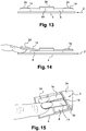
- this flat face 21 forming the end edge of the body is inclined slightly in the direction of the other end of the body to facilitate the angular movement of the tigelle illustrated in Figures 14 and 15 .
- the display rack is arranged to allow a maximum angular deflection of the tab up 17 ° upwards from the horizontal plane defined by the upper face of the pedestal 8.
- This angle value is given for information only, and it is not limiting. It is thus possible to move the distance between the tab and the wall 4 from 3 to 17 mm for example.
- the distance of 3 mm corresponds to the rest position of the tigels where the lower face of their body 15 rests against the base 8, that is to say that this distance is substantially equal to the thickness of the base.
- the starting distance is between 2 and 10 mm and the final distance between 12 and 30 mm.
- Each tab also includes a part 24 attached to the body 15, forming a nail model and tinted in the mass.
- the hue is chosen to be different from that of all other tigels. It corresponds to the hue of a nail polish intended to be sold elsewhere.
- the piece 24 thus has a generally flat shape intended to be fixed on the upper face of the body 15, at the free end 18 and so that at this end, the edges of the part coincide with those of the body.
- the piece 24 carries a relief 26 projecting from its lower face and intended to penetrate into an opening 28 of the body 15.
- This relief itself has an elongated shape rounded to only one of its two ends, just like the opening 28, to provide a keying for fixing the part on the body.
- only one of the end edges of the piece 24 can come into coincidence with the end of the body 15.
- the lower face of the piece 24 has a flat shape just like the area of the upper face of the body intended to to receive it.
- the upper face 30 of the piece 24 has a slightly convex general shape imitating that of a fingernail and thus has curvatures in planes not parallel to each other.
- the part 24 has in plan a generally flared shape having two main lateral edges 32 going away from one another as one approaches the free end 18 of the tigelle.
- the end of the piece 24 contiguous to the free end of the body is wider than the other end of this piece. This shape approaches that of a natural nail and allows a more realistic rendering when the piece 24 is above the finger of a user as will be seen later.
- the body 15 is given a thickness e which decreases when one moves along the tab from the retaining end 16 to the free end 18.
- the smaller thickness in the vicinity of this end allows to bring the tinted portion of the tigelle closer to the user's finger below.
- Each body 15 has a cavity 17 formed in its lower face to the right of the tinted portion.
- the orifice 28 extends into this cavity. It allows to receive part of the user's nail when placing his finger under the tigelle, which allows to better appreciate the effect of the color at the end of the finger.
- the free portion of this face may be coated with inscriptions and drawings.
- the display unit further comprises a shutter, or mask, elongate rectangular plate 34 adapted to cover the base 10 by closing all the housing 12 simultaneously and by masking them. Thus, the exit of the tigelles out of their houses is prohibited.
- the rigid attachment of the shutter 34 to the base 10 is provided in this case by magnetic means formed here by three magnets 36 of the base illustrated in FIG. figure 12 .
- the polarity of each magnet is oriented according to the thickness of the base and the magnets are following in its longitudinal direction. In this case, the north pole of the central magnet is oriented downwards while that of the magnets at the longitudinal ends of the base is oriented upwards.
- the magnetic means also comprise in the shutter three analogous magnets 38 arranged in the same way as those of the base with polarities complementary to those of the magnets of the base to ensure the magnetic attachment of the shutter at the base.
- fixing the shutter at the base is performed by identical means except that the polarity magnets is reversed. In this way, it ensures not only the rigid attachment of the corresponding shutter 34 to its own base 10, but in addition, it ensures the maintenance of the display in the closed position of the figure 1 in that the magnets of the two shutters 34 placed against each other in this position attract each other.
- the width of the intermediate wall 6 is chosen so that, in the closed position, the upper faces of the shutters 34 come into contact and bear against each other.
- the strength of the magnets is chosen to allow to separate the shutter from its base without difficulty when desired or to allow to open the display at will.
- the walls 4, the bases 8, the bases 10 and the shutters 34 thus form a support for the tigels.
- They can be made of plastic for example, just like the tigels.
- the body of the pins is for example a length of about 50 mm and a width of about 10 mm.
- all the walls as well as the shutters are black on all their visible faces. This choice highlights the different shades worn by the tigels. This black color, too, makes it easier to read the inscriptions worn by the tigelle, especially when these inscriptions are white. Of course, other color choices are possible for these walls.
- the body of the pins is here made of a transparent material, this is a preferred embodiment, but not limiting.
- the display is open, its main walls 4 being horizontal and in the extension of one another in the same plane.
- the tigels are retained in the corresponding housing 12.
- the body of each tab rests by gravity on the base 8. Thanks to this flat support of all the tigelles, the tabs extend globally in the same horizontal plane.
- the end of each tigel bearing the tinted piece extends to the right and away from the wall 4, beyond the base 8 according to the height, without the latter being interposed between them.
- the wall 4 is visible over a large part of the periphery of the tab and in particular around its end bearing the tinted portion.
- the support could comprise a single assembly formed by the main wall 4, the base 8, the base 10 and the shutter 34.
- the parts 24 are not necessarily tinted in the mass. They could receive on the surface a layer of varnish or any other decoration monochrome or polychrome.
- the tigels with their piece 24 could be built differently.
- the tab and the piece 24 could be one-piece, molded in one piece, the area corresponding to the part 24 initially having the appearance of the tab and then receiving a layer of varnish or other monochrome decoration or with patterns of different colours.
Description
L'invention concerne les présentoirs pour des teintes de vernis à ongles.The present invention relates to display stands for nail polish tints.
Un tel présentoir est parfois appelé onglier. Il est utilisé dans un lieu de vente et permet aux clients de choisir des teintes de vernis à ongles.Such a display is sometimes called onglier. It is used in a place of sale and allows customers to choose colors of nail polish.
Les présentoirs existants de ce type ont la forme générale d'une palette ronde ou rectangulaire avec des sortes de pétales qui sont orientés vers l'extérieur. Les pétales ont la forme de l'ongle d'un doigt, et ils sont décorés. L'utilisateur qui souhaite choisir une couleur ou une décoration pour ses ongles a la possibilité de superposer un des pétales de la palette sur un ongle de sa main.Existing displays of this type have the general shape of a round or rectangular pallet with kinds of petals that are oriented outwards. The petals have the shape of a fingernail, and they are decorated. The user who wishes to choose a color or a decoration for his nails has the possibility of superimposing one of the petals of the palette on a fingernail of his hand.
Un tel présentoir est par exemple connu du document
Pour certain ongliers, les pétales sont montés sur la palette avec un système de pince élastique qui permet de les démonter pour le cas échéant les remplacer par d'autres pétales.For some nail, the petals are mounted on the pallet with a system of resilient clip which allows to disassemble them if necessary to replace them with other petals.
Mais ces opérations sont relativement malaisées à effectuer et compliquent le choix des teintes. En particulier, il faut tenir en main toute la palette pour faire la superposition d'un pétale avec un ongle, et en opérant ainsi, aucune des mains ne repose sur un support ferme.But these operations are relatively difficult to perform and complicate the choice of colors. In particular, it is necessary to hold in hand the whole pallet to make the superposition of a petal with a fingernail, and in doing so, none of the hands rests on a firm support.
Un but de l'invention est de faciliter ce choix.An object of the invention is to facilitate this choice.
À cet effet, on prévoit selon l'invention un présentoir pour des teintes de vernis à ongles, qui comporte un support et des tigelles teintées montées mobiles sur le support indépendamment les unes des autres.For this purpose, there is provided according to the invention a display for colors of nail polish, which comprises a support and tinted stems mounted movably on the support independently of one another.
Ainsi, en déplaçant la tigelle par rapport aux autres sans lui faire quitter le support, il est possible de considérer sa teinte indépendamment de celle des autres. On s'épargne donc les opérations de montage et de remontage que l'on connaissait avec le présentoir de l'art antérieur présenté ci-dessus. On peut successivement placer son doigt sous différentes tigelles. Il est donc plus facile et rapide d'essayer différentes teintes à la suite.Thus, by moving the tigelle relative to others without leaving the support, it is possible to consider its hue independently of that of others. It avoids the assembly and reassembly operations that we knew with the display of the prior art presented above. You can successively place your finger under different tigels. It is therefore easier and faster to try different shades as a result.
De préférence, chaque tigelle est montée librement mobile à rotation sur le support.Preferably, each tab is mounted freely rotatable on the support.
Avantageusement, chaque tigelle est montée mobile entre une position de repos et une position d'essai dans laquelle la partie teintée s'étend à plus grande distance d'une paroi de fond du support que dans la position de repos.Advantageously, each tab is movably mounted between a rest position and a test position in which the tinted portion extends at a greater distance from a bottom wall of the support than in the rest position.
Par conséquent, pour essayer une teinte, l'utilisateur glisse son doigt entre la paroi de fond et la tigelle choisie.Therefore, to try a shade, the user slides his finger between the bottom wall and the chosen tab.
On peut prévoir également que chaque tigelle est montée de façon amovible sur le support.It can also be provided that each tab is mounted removably on the support.
Il est donc facile de remplacer certaines tigelles par d'autres pour mettre à jour les teintes par exemple.It is therefore easy to replace some tigels with others to update tints for example.
Selon l'invention, le support présente des logements de retenue des tigelles, les logements étant profilés suivant une direction perpendiculaire à un plan principal du support.According to the invention, the support has retaining housings of the tigels, the housing being profiled in a direction perpendicular to a main plane of the support.
Il s'agit d'un agencement commode pour le montage des tigelles dans le support.This is a convenient arrangement for mounting the pins in the holder.
Selon l'invention, les tigelles sont reçues dans les logements avec un jeu propre à permettre à lui seul une rotation des tigelles par rapport au support.According to the invention, the tigels are received in the housing with a game proper to allow alone a rotation of the tigels relative to the support.
Ainsi il n'est pas nécessaire de prévoir des moyens spécifiques pour le montage à rotation des tigelles sur le support.Thus it is not necessary to provide specific means for the rotational mounting of the rods on the support.
Avantageusement, le présentoir comporte au moins un obturateur apte à obturer une ouverture des logements servant à y introduire les tigelles, en masquant les ouvertures.Advantageously, the display comprises at least one shutter capable of closing an opening of the housings used to introduce the pins, masking the openings.
L'obturateur assure donc à la fois la fermeture des ouvertures et leur masquage.The shutter thus ensures both the closure of the openings and their masking.
De préférence, le présentoir comprend des moyens magnétiques de maintien de l'obturateur contre les ouvertures.Preferably, the display comprises magnetic means for holding the shutter against the openings.
Avantageusement, le présentoir comprend :
- au moins deux volets mobiles l'un par rapport à l'autre pour définir des positions respectivement ouverte et fermée du présentoir, et aptes à s'étendre en regard l'un de l'autre en position fermée du présentoir, et
- des moyens magnétiques de maintien du présentoir en position fermée.
- at least two flaps movable relative to each other to define respectively open and closed positions of the display, and able to extend facing each other in the closed position of the display, and
- magnetic means for holding the display in the closed position.
De préférence, les obturateurs sont au moins au nombre de deux et forment les moyens de maintien en position fermée.Preferably, the shutters are at least two in number and form the holding means in the closed position.
Ainsi ce sont les mêmes moyens magnétiques qui assurent l'immobilisation des obturateurs sur les ouvertures et celle du présentoir en position fermée.Thus it is the same magnetic means that ensure the immobilization of the shutters on the openings and that of the display in the closed position.
Avantageusement, chaque tigelle présente une partie teintée dans la masse avec une teinte différente de la teinte d'au moins une autre des tigelles.Advantageously, each tigelle has a tinted portion in the mass with a different shade of the shade of at least one other tigella.
La réalisation d'une teinte dans la masse permet de la rendre plus fidèle au vernis qu'elle représente et produit un meilleur rendu.The achievement of a hue in the mass makes it more faithful to the varnish it represents and produces a better result.
De préférence, chaque tigelle présente une partie teintée de forme évasée allant en s'élargissant en direction d'une extrémité libre de la tigelle.Preferably, each tab has a tinted portion of flared shape widening towards a free end of the tab.
De la sorte, la forme de la partie teintée se rapproche de la forme naturelle d'un ongle et permet donc de mieux apprécier l'effet obtenu avec la teinte.In this way, the shape of the tinted part is closer to the natural shape of a nail and thus allows to better appreciate the effect obtained with the hue.
Dans un mode de réalisation, chaque tigelle comprend un corps sur lequel est rapportée la partie teintée.In one embodiment, each tab comprises a body on which the tinted portion is attached.
Ainsi les tigelles peuvent avoir des corps identiques et on simplifie la fabrication du présentoir.Thus the tigels can have identical bodies and it simplifies the manufacture of the display.
Avantageusement, chaque tigelle comprend un corps qui présente une épaisseur qui diminue à mesure qu'on se rapproche d'une extrémité libre de la tigelle.Advantageously, each tigelle comprises a body which has a thickness which decreases as one approaches a free end of the tigelle.
De la sorte, on accroît la proximité de la partie teintée avec l'ongle du doigt de l'utilisateur durant l'essai.In this way, the proximity of the tinted part with the nail of the finger is increased. the user during the test.
De préférence, chaque tigelle présente une cavité ménagée dans une face inférieure de la tigelle au droit de la partie teintée.Preferably, each tab has a cavity in a lower face of the tab to the right of the tinted portion.
Cette cavité permet de recevoir au moins une partie de l'ongle de l'utilisateur lorsqu'il place son doigt sous la tigelle, ce qui permet de mieux apprécier l'effet de la teinte à l'extrémité du doigt.This cavity allows to receive at least a portion of the user's nail when placing his finger under the tab, which allows to better appreciate the effect of the color at the end of the finger.
Avantageusement, le présentoir comprend une paroi de fond et un socle agencés de sorte que, en position de repos de chaque tigelle, la paroi de fond est visible autour de celle-ci et le socle supporte la tigelle à distance de la paroi de fond.Advantageously, the display comprises a bottom wall and a base arranged so that, in the rest position of each tab, the bottom wall is visible around it and the base supports the tab away from the bottom wall.
La paroi de fond, qui sera de préférence de couleur uniforme, permet une meilleure comparaison des teintes entre elles. La distance améliore la visibilité des tigelles par rapport à la paroi de fond et facilite l'introduction d'un doigt entre la tigelle et cette paroi.The bottom wall, which will preferably be of uniform color, allows a better comparison of the hues between them. The distance improves the visibility of the pins relative to the bottom wall and facilitates the introduction of a finger between the tab and this wall.
De préférence, la paroi de fond au moins a une couleur noire.Preferably, the bottom wall at least has a black color.
Cette couleur neutre et sombre fait bien ressortir les parties teintées des tigelles.This neutral and dark color highlights the tinted parts of the tigels.
On prévoit également selon l'invention un procédé de sélection d'une teinte de vernis à ongles, dans lequel on fournit un présentoir tel que décrit ci-dessus, on déplace l'une des tigelles par rapport au support, indépendamment des autres tigelles et de sorte qu'elle demeure reliée au support, et on place un doigt sous la tigelle déplacée.Also provided according to the invention is a method of selecting a nail polish color, in which a display as described above is provided, one of the tabs is moved relative to the support, independently of the other pins and so that it remains connected to the support, and a finger is placed under the shifted stalk.
Nous allons maintenant présenter un mode de réalisation de l'invention en référence aux dessins annexés sur lesquels :
- les
figures 1 et 2 sont des vues respectivement en perspective et en élévation d'un présentoir selon un mode de réalisation de l'invention respectivement en position fermée et en position ouverte ; - la
figure 3 est une vue à plus grande échelle d'une partie du présentoir de lafigure 2 avec l'un des obturateurs ôté ; - les
figures 4 à 7 sont des vues en perspective, de dessus et de côté du corps d'une des tigelles du présentoir des figures précédentes ; - les
figures 8 à 11 sont des vues en perspective, en coupe longitudinale et en vue d'extrémité de la partie teintée de l'une des tigelles du présentoir desfigures 1 à 3 ; - la
figure 12 montre l'agencement des aimants dans le présentoir de ce mode de réalisation ; et - les
figures 13 à 15 sont des vues de côté et en perspective illustrant des étapes de l'utilisation du présentoir desfigures 1 à 3 .
- the
Figures 1 and 2 are views respectively in perspective and in elevation of a display according to an embodiment of the invention respectively in the closed position and in the open position; - the
figure 3 is a larger-scale view of a portion of the display stand of thefigure 2 with one of the shutters removed; - the
Figures 4 to 7 are views in perspective, from above and from the body of one of the tigels of the display of the preceding figures; - the
Figures 8 to 11 are perspective views, in longitudinal section and end view of the tinted portion of one of the tigels of the display ofFigures 1 to 3 ; - the
figure 12 shows the arrangement of the magnets in the display of this embodiment; and - the
Figures 13 to 15 are side and perspective views illustrating steps in the use of the display standFigures 1 to 3 .
Nous allons décrire un mode de réalisation du présentoir de l'invention en référence aux
Le présentoir 2 comprend ici deux parois principales ou parois de fond 4, en l'espèce de forme rectangulaire, identiques entre elles et reliées l'une à l'autre par une paroi intermédiaire 6 à la façon d'un livre. Ces trois parois sont plates. Ainsi chacune des deux parois 4 est articulée à la paroi intermédiaire et peut venir en regard de l'autre paroi principale pour former la position fermée du présentoir illustrée à la
En l'espèce, les deux parties du présentoir associées aux parois principales respectives 4 sont identiques l'une à l'autre (mis à part la polarité des aimants comme nous le verrons plus loin) et symétriques l'une de l'autre comme on le voit à la
Dans la suite, nous désignerons par « direction longitudinale » la direction allant de l'une à l'autre de ces deux parties et par « hauteur » la direction perpendiculaire à cette dernière et parallèle aux parois 4.In the following, we will designate by "longitudinal direction" the direction going from one to the other of these two parts and by "height" the direction perpendicular to the latter and parallel to the
La paroi 4 porte un socle plat rectangulaire 8 ayant une face inférieure appliquée contre la face supérieure de la paroi 4. Les côtés du socle s'étendant suivant la hauteur du présentoir coïncident avec ceux de la paroi principale 4. Ses côtés parallèles à la direction longitudinale s'étendent à distance de ceux de la paroi 4 mais parallèlement à ceux-ci.The
Le socle 8 porte à son tour une base plate rectangulaire 10 ou porte-tigelles ayant une face inférieure appliquée contre la face supérieure du socle 8. Cette base présente deux bords longitudinaux dans lesquels sont ménagés des logements 12 identiques entre eux. Chaque logement est profilé suivant une direction perpendiculaire au plan de la paroi 4. Le profil a en l'espèce une forme générale en « T ». Chaque logement est ouvert dans cette direction vers le haut et également en direction du bord longitudinal du socle 8 le plus proche.The
Le présentoir 2 comprend également des tigelles 14 destinées à être reçues et retenues dans les logements respectifs et que nous allons maintenant décrire en référence aux
Chaque tigelle 14 comprend un corps 15 présentant une forme générale plate allongée délimitée par deux bords longitudinaux rectilignes parallèles entre eux et destinés à s'étendre suivant la direction de la hauteur du présentoir. Le corps présente une extrémité de fixation 16 et une extrémité libre 18 opposées l'une à l'autre suivant la direction longitudinale du corps.Each
L'extrémité de fixation 16 présente en plan une forme de « T » complémentaire de celle des logements 12. Elle est destinée à être reçue dans l'un quelconque de ceux-ci suivant un agencement mâle-femelle en introduisant la tigelle à partir de l'ouverture supérieure du logement. En particulier, cette extrémité présente deux reliefs tels que des oreilles 20 s'étendant en saillie des bords longitudinaux du corps, en directions opposées l'une à l'autre.The fixing
Le logement 12 et le corps 15 sont agencés de sorte que, dans cette position, la tigelle est librement mobile à rotation par rapport à la base autour d'un axe de rotation parallèle à la direction longitudinale du présentoir. La retenue de la tigelle dans le logement est assurée par la complémentarité de forme entre l'extrémité 16 et le logement. Quant au mouvement de rotation, il est rendu possible par un biseau 21 qui forme la face arrière de l'élément de fixation 16. Ainsi, cette face plane 21 formant le bord d'extrémité du corps est inclinée légèrement en direction de l'autre extrémité du corps pour faciliter le débattement angulaire de la tigelle illustré aux
On prévoit par exemple que le présentoir est agencé pour autoriser un débattement angulaire maximal de la tigelle sur 17° vers le haut à partir du plan horizontal défini par la face supérieure du socle 8. Cette valeur d'angle est donnée à titre indicatif, et elle n'est pas limitative. On peut ainsi faire passer la distance entre la tigelle et la paroi 4 de 3 à 17 mm par exemple. La distance de 3 mm correspond à la position de repos des tigelles où la face inférieure de leur corps 15 repose contre le socle 8, c'est-à-dire que cette distance est sensiblement égale à l'épaisseur du socle. Plus généralement, on peut prévoir que la distance de départ est comprise entre 2 et 10 mm et la distance finale entre 12 et 30 mm.For example, it is provided that the display rack is arranged to allow a maximum angular deflection of the tab up 17 ° upwards from the horizontal plane defined by the upper face of the
Chaque tigelle comporte également une pièce 24 rapportée sur le corps 15, formant un modèle d'ongle et teintée dans la masse. La teinte est choisie pour être différente de celle de toutes les autres tigelles. Elle correspond à la teinte d'un vernis à ongles destiné à être vendu par ailleurs.Each tab also includes a
La pièce 24 présente ainsi une forme générale plate destinée à être fixée sur la face supérieure du corps 15, à l'extrémité libre 18 et de sorte que, à cette extrémité, les bords de la pièce viennent en coïncidence avec ceux du corps. En vue de la fixation, la pièce 24 porte un relief 26 s'étendant en saillie de sa face inférieure et destiné à pénétrer dans une ouverture 28 du corps 15. Ce relief a lui-même une forme allongée arrondie à une seule de ses deux extrémités, tout comme l'ouverture 28, afin de fournir un détrompage pour la fixation de la pièce sur le corps. Ainsi, seul l'un des bords d'extrémité de la pièce 24 peut venir en coïncidence avec l'extrémité du corps 15. La face inférieure de la pièce 24 a une forme plane tout comme la zone de la face supérieure du corps destinée à la recevoir. On peut par exemple fixer la pièce 24 au corps au moyen d'un soudage par ultrasons.The
La face supérieure 30 de la pièce 24 a une forme générale légèrement bombée imitant celle d'un ongle et présente ainsi des courbures dans des plans non parallèles entre eux.The
La pièce 24 a en plan une forme générale évasée présentant deux bord latéraux principaux 32 allant en s'éloignant l'un de l'autre à mesure qu'on s'approche de l'extrémité libre 18 de la tigelle. Ainsi, l'extrémité de la pièce 24 contiguë à l'extrémité libre du corps est plus large que l'autre extrémité de cette pièce. Cette forme approche celle d'un ongle naturel et permet un rendu plus réaliste lorsque la pièce 24 se trouve au-dessus du doigt d'un utilisateur comme on le verra plus loin.The
Comme illustré à la
Chaque corps 15 présente une cavité 17 ménagée dans sa face inférieure au droit de la partie teintée. L'orifice 28 s'étend dans cette cavité. Elle permet de recevoir une partie de l'ongle de l'utilisateur lorsqu'il place son doigt sous la tigelle, ce qui permet de mieux apprécier l'effet de la teinte à l'extrémité du doigt.Each
Sachant que la pièce 24 ne recouvre pas toute la face supérieure du corps 15, la partie libre de cette face peut être revêtue d'inscriptions et de dessins.Knowing that the
Le présentoir comprend en outre un obturateur, ou masque, plat rectangulaire allongé 34 apte à recouvrir la base 10 en obturant tous les logements 12 simultanément et en masquant ceux-ci. Ainsi, la sortie des tigelles hors de leurs logements est interdite.The display unit further comprises a shutter, or mask, elongate
La fixation rigide de l'obturateur 34 à la base 10 est assurée en l'espèce par des moyens magnétiques formés ici par trois aimants 36 de la base illustrés à la
Les moyens magnétiques comprennent également dans l'obturateur trois aimants analogues 38 agencés de la même façon que ceux de la base avec des polarités complémentaires de celles des aimants de la base pour assurer la fixation magnétique de l'obturateur à la base.The magnetic means also comprise in the shutter three
Dans l'autre partie du présentoir illustrée à gauche sur la
La force des aimants est choisie pour permettre de séparer l'obturateur de sa base sans difficulté lorsqu'on le souhaite ou encore pour permettre d'ouvrir le présentoir à volonté.The strength of the magnets is chosen to allow to separate the shutter from its base without difficulty when desired or to allow to open the display at will.
Les parois 4, les socles 8, les bases 10 et les obturateurs 34 forment ainsi un support pour les tigelles. Mis à part les aimants, ils peuvent être réalisés en matière plastique par exemple, tout comme les tigelles. Le corps des tigelles a par exemple une longueur d'environ 50 mm et une largeur d'environ 10 mm.The
Dans le présent exemple, toutes les parois ainsi que les obturateurs sont de couleur noire sur toutes leurs faces visibles. Ce choix met en valeur les différentes teintes portées par les tigelles. Cette couleur noire, également, facilite la lecture des inscriptions portées par la tigelle, en particulier lorsque ces inscriptions sont de couleur blanche. Naturellement, d'autres choix de couleurs sont possibles pour ces parois. Le corps des tigelles est ici réalisé dans un matériau transparent, ceci est un mode de réalisation préféré, mais non limitatif.In the present example, all the walls as well as the shutters are black on all their visible faces. This choice highlights the different shades worn by the tigels. This black color, too, makes it easier to read the inscriptions worn by the tigelle, especially when these inscriptions are white. Of course, other color choices are possible for these walls. The body of the pins is here made of a transparent material, this is a preferred embodiment, but not limiting.
Nous allons maintenant présenter l'utilisation du présentoir en référence aux
En référence à la
Lorsque l'utilisateur souhaite faire l'essai ou le test de l'une des teintes de vernis à ongles, comme illustré aux
Bien entendu, on pourra apporter à l'invention de nombreuses modifications sans sortir du cadre de celle-ci, tel que défini par les revendications annexées.Of course, many modifications can be made to the invention without departing from the scope thereof, as defined by the appended claims.
Le support pourrait comprendre un seul ensemble formé par la paroi principale 4, le socle 8, la base 10 et l'obturateur 34.The support could comprise a single assembly formed by the
On pourra se dispenser de prévoir les parois principales 4.We can dispense with providing the
Les pièces 24 ne sont pas nécessairement teintées dans la masse. Elles pourraient recevoir en surface une couche de vernis ou toute autre décoration monochrome ou polychrome.The
Les tigelles avec leur pièce 24 pourraient être construites de façon différente. Par exemple la tigelle et la pièce 24 pourraient être monobloc, moulées en une seule pièce, la zone correspondant à la pièce 24 ayant initialement l'aspect de la tigelle et recevant ensuite une couche de vernis ou une autre décoration monochrome ou avec des motifs de différentes couleurs.The tigels with their
On pourra modifier le nombre ou la disposition des aimants. On pourra assurer le maintien des obturateurs sur les bases ou le maintien du présentoir en position fermée par d'autres moyens que des moyens magnétiques.We can change the number or arrangement of magnets. It will be possible to maintain the shutters on the bases or the maintenance of the display in the closed position by means other than magnetic means.
Claims (15)
- Display rack (2) for shades of nail varnish, the display rack comprising:- a support (4, 8, 10, 34) and- coloured tabs (14) which are mounted on the support in a mobile manner, the support having housings (12) to hold the tabs, the housings being profiled in a direction perpendicular to a main plane of the support, the tabs being held in the housings (12), and the display rack being adapted to successively place a finger under each tab, such that the tabs (12) are held in the housings (12) with sufficient clearance to allow them to rotate relative to the support, the tabs (12) all being held separately on the support, all mounted in a mobile manner independently from each other and all removably mounted independently from each other.
- Display rack according to at least any one of the preceding claims wherein each tab is mounted movably between a rest position and a test position in which a coloured part of the tab extends farther from a bottom wall (4) of the support than in the rest position.
- Display rack according to at least any one of the preceding claims wherein the housings are profiled in a direction perpendicular to a main plane of the support.
- Display rack according to at least any one of the preceding claims which comprises at least one cover (34) able to close an opening of the housings used to insert the tabs, hiding the openings.
- Display rack according to the preceding claim which comprises magnetic means (36, 38) for holding the cover against the openings.
- Display rack according to at least any one of the preceding claims which comprises:- at least two flaps movable relative to each other to define respectively opened and closed positions of the display rack, and adapted to extend opposite one another when the display rack is in the closed position, and- magnetic means (38) for holding the display rack in the closed position.
- Display rack according to claims 5 and 6 wherein there are at least two covers (34) which form the means for holding in the closed position.
- Display rack according to at least any one of the preceding claims wherein each tab has a body-dyed part (24) with a shade different from that of at least another one of the tabs.
- Display rack according to at least any one of the preceding claims wherein each tab has a flared coloured part (24) that widens towards a free end of the tab.
- Display rack according to at least any one of claims 8 to 9 wherein each tab comprises a body (15) to which the coloured part is attached.
- Display rack according to at least any one of the preceding claims wherein each tab comprises a body (15) whose thickness decreases on approaching a free end of the tab.
- Display rack according to at least any one of the preceding claims wherein each tab has a coloured part and a cavity (17) formed in a lower side of the tab at the coloured part.
- Display rack according to at least any one of the preceding claims which comprises a bottom wall (4) and a stand (8) arranged so that, when each tab is in the rest position, the bottom wall is visible around it and the stand supports the tab at a distance from the bottom wall.
- Display rack according to the preceding claim wherein at least the bottom wall (4) is black.
- Method for selecting a shade of nail varnish, characterised in that a display rack (2) is supplied according to one of the preceding claims, one of the tabs is moved relative to the support, independently of the other tabs and so that it remains connected to the support, and a finger is placed under the tab which has been moved.
Applications Claiming Priority (2)
| Application Number | Priority Date | Filing Date | Title |
|---|---|---|---|
| FR1360032A FR3011722B1 (en) | 2013-10-15 | 2013-10-15 | DISPLAY FOR NAIL VARNISH SHADES |
| PCT/FR2014/052609 WO2015055940A1 (en) | 2013-10-15 | 2014-10-14 | Display rack for shades of nail varnish |
Publications (2)
| Publication Number | Publication Date |
|---|---|
| EP3057461A1 EP3057461A1 (en) | 2016-08-24 |
| EP3057461B1 true EP3057461B1 (en) | 2018-10-03 |
Family
ID=50023725
Family Applications (1)
| Application Number | Title | Priority Date | Filing Date |
|---|---|---|---|
| EP14799512.0A Not-in-force EP3057461B1 (en) | 2013-10-15 | 2014-10-14 | Display rack for shades of nail varnish |
Country Status (7)
| Country | Link |
|---|---|
| US (1) | US10327534B2 (en) |
| EP (1) | EP3057461B1 (en) |
| JP (1) | JP6509203B2 (en) |
| KR (1) | KR20160074549A (en) |
| CN (1) | CN105848516A (en) |
| FR (1) | FR3011722B1 (en) |
| WO (1) | WO2015055940A1 (en) |
Families Citing this family (1)
| Publication number | Priority date | Publication date | Assignee | Title |
|---|---|---|---|---|
| US20190191851A1 (en) * | 2017-12-22 | 2019-06-27 | Michael Esposito | Nail Polish Display |
Family Cites Families (32)
| Publication number | Priority date | Publication date | Assignee | Title |
|---|---|---|---|---|
| US383389A (en) * | 1888-05-22 | Educational device | ||
| US2020100A (en) * | 1933-11-16 | 1935-11-05 | Northam Warren Corp | Manicuring stand |
| US1990630A (en) * | 1934-01-04 | 1935-02-12 | Northam Warren Corp | Tester for finger nail color |
| GB421510A (en) * | 1934-04-04 | 1934-12-21 | Duryea Bensel | Improvements in color tester |
| US2195495A (en) * | 1937-07-06 | 1940-04-02 | Fort Orange Chemical Co Inc | Package |
| US2417677A (en) * | 1945-10-11 | 1947-03-18 | Albert M Cohan | Display card |
| US2840088A (en) * | 1955-12-27 | 1958-06-24 | Kushner Arnold | Fingernail mask |
| CH355912A (en) * | 1959-07-16 | 1961-07-31 | Mecanique & Plastique S A | Box |
| US2987827A (en) * | 1960-09-06 | 1961-06-13 | Sr Andrew Carnegie | Visual aid mathematics educational device |
| US3703040A (en) * | 1970-07-06 | 1972-11-21 | Raymond Roger Hill | Keyboard teaching aid |
| US4140139A (en) * | 1976-02-25 | 1979-02-20 | Aylott Eric V | Mounting and packaging of artificial fingernails |
| JPS5734520Y2 (en) * | 1979-01-25 | 1982-07-30 | ||
| JPS5939922Y2 (en) * | 1982-06-02 | 1984-11-10 | 株式会社資生堂 | Manicure color swatch display |
| USD299878S (en) * | 1986-05-12 | 1989-02-14 | Zotos International, Inc. | Combined artificial fingernail tip selector guide and support and display |
| US5154656A (en) * | 1991-05-09 | 1992-10-13 | Linda Milstein | Multi-connecting building blocks |
| USD345442S (en) * | 1992-04-29 | 1994-03-22 | Gillan Margaret A | Nail polish selector |
| FR2719557B1 (en) * | 1994-05-06 | 1996-07-26 | Ppi Sa | Display of removable objects and machine for making a part of this display. |
| US5570793A (en) * | 1995-02-24 | 1996-11-05 | Killough; Beverly A. | Fingernail color display |
| USD386823S (en) * | 1996-09-11 | 1997-11-25 | Carroll George H | Combination artificial fingernails and sizing ring |
| JP3393174B2 (en) * | 1997-04-22 | 2003-04-07 | カネボウ株式会社 | Manicure sample display |
| US5988178A (en) * | 1998-09-04 | 1999-11-23 | Bair; Christina S. | Nail tip sizing tool and method of manufacture thereof |
| US6598608B1 (en) * | 2000-07-12 | 2003-07-29 | Margarita Downey | Cosmetics sampling method and cosmetics sampler film |
| US6964110B2 (en) * | 2003-02-07 | 2005-11-15 | It's Academic Of Illinois, Inc. | Ruler |
| US6892736B2 (en) * | 2003-03-07 | 2005-05-17 | Kmc Exim Corp. | Artificial nail having application tab |
| US7354272B1 (en) * | 2004-09-27 | 2008-04-08 | Marc David Zev | Manipulative tile as learning tool |
| CA2683087A1 (en) * | 2007-04-12 | 2008-04-12 | The Procter & Gamble Company | Cosmetic color-selection tool |
| US8662305B2 (en) | 2010-06-09 | 2014-03-04 | Kiss Nail Products, Inc. | Artificial nail display package |
| US20120178055A1 (en) * | 2011-01-12 | 2012-07-12 | Michael Reyzis | Color spoon |
| US8616886B2 (en) * | 2011-06-27 | 2013-12-31 | Michael Clark | Display for viewing colorswatches |
| CN202853752U (en) * | 2012-09-29 | 2013-04-03 | 天津市华颖印刷有限公司 | Nail polish color plate |
| WO2015081265A1 (en) * | 2013-11-27 | 2015-06-04 | One Source Industries, Llc | Beauty product displays |
| USD752289S1 (en) * | 2014-06-16 | 2016-03-22 | Muriel Tegtmeyer | Color organizer |
-
2013
- 2013-10-15 FR FR1360032A patent/FR3011722B1/en not_active Expired - Fee Related
-
2014
- 2014-10-14 KR KR1020167012674A patent/KR20160074549A/en active Search and Examination
- 2014-10-14 EP EP14799512.0A patent/EP3057461B1/en not_active Not-in-force
- 2014-10-14 CN CN201480056208.3A patent/CN105848516A/en active Pending
- 2014-10-14 WO PCT/FR2014/052609 patent/WO2015055940A1/en active Application Filing
- 2014-10-14 JP JP2016521669A patent/JP6509203B2/en not_active Expired - Fee Related
- 2014-10-14 US US15/027,100 patent/US10327534B2/en not_active Expired - Fee Related
Non-Patent Citations (1)
| Title |
|---|
| None * |
Also Published As
| Publication number | Publication date |
|---|---|
| WO2015055940A1 (en) | 2015-04-23 |
| EP3057461A1 (en) | 2016-08-24 |
| US20160235185A1 (en) | 2016-08-18 |
| JP6509203B2 (en) | 2019-05-08 |
| FR3011722A1 (en) | 2015-04-17 |
| FR3011722B1 (en) | 2016-10-28 |
| US10327534B2 (en) | 2019-06-25 |
| KR20160074549A (en) | 2016-06-28 |
| JP2016536049A (en) | 2016-11-24 |
| CN105848516A (en) | 2016-08-10 |
Similar Documents
| Publication | Publication Date | Title |
|---|---|---|
| EP3225123B1 (en) | Device for dispensing artificial eyelashes | |
| FR2541882A1 (en) | CONDIMENT SECURING DEVICE | |
| CA2178850A1 (en) | Tridimensional article assembled from puzzle-like pieces | |
| EP3057461B1 (en) | Display rack for shades of nail varnish | |
| FR2930120A1 (en) | CASE DISTRIBUTOR OF COSMETIC PRODUCT. | |
| FR2610183A1 (en) | CONFERENCE BRIDGE | |
| WO2014029935A1 (en) | Device for applying additional eyelashes to the eyelashes of a person's eyelid | |
| EP3071067A1 (en) | Device for distributing artificial eyelashes | |
| EP2282821B1 (en) | Game including small magnetically juxtaposable and stackable cubes | |
| FR2854874A1 (en) | Modular box, e.g. for cosmetic products, has hinged sections with pivots formed by magnets with unlike poles facing one another | |
| FR2654858A1 (en) | Signalling module | |
| FR2936945A1 (en) | SUPPORT FOR HANGING AN OBJECT BY HIS HANDLE | |
| EP3801371B1 (en) | Device for storing orthodontic pliers | |
| FR2570263A1 (en) | Display device for spectacles | |
| EP0010806B1 (en) | Tamper-proof label holder | |
| EP0470908B1 (en) | Presentation device from units, having in the same plane modifiable relative positions | |
| FR2725702A1 (en) | Bin for selective collection of waste | |
| FR2625889A1 (en) | Frame for a flat object | |
| EP3991597A1 (en) | Support for cosmetic product, assembly of said support and said product and container provided with said assembly | |
| FR2639136A1 (en) | Games and/or teaching panel or the like including on its surface patterns which can be changed or completed as required | |
| FR2960397A3 (en) | Support for hooking object e.g. bag, to edge of board table, has case shaped backing plate comprising hook connected to pivot, and interdependent and removable pivots whose axes are aligned, where plate is supported on top of holder | |
| FR3046920A1 (en) | BOX FOR WRITING INSTRUMENTS | |
| CH280787A (en) | Glass support for at least one sheet bearing an image. | |
| FR2657185A1 (en) | Device for presenting information carried by a medium in the form of a sheet | |
| FR2907020A1 (en) | Maze type toy, has cylindrical peripheral cover provided with network of channels forming maze, and object e.g. ball, passing though network, where body is in shape of cylindrical drum or portion of drum in longitudinal axis |
Legal Events
| Date | Code | Title | Description |
|---|---|---|---|
| PUAI | Public reference made under article 153(3) epc to a published international application that has entered the european phase |
Free format text: ORIGINAL CODE: 0009012 |
|
| 17P | Request for examination filed |
Effective date: 20160419 |
|
| AK | Designated contracting states |
Kind code of ref document: A1 Designated state(s): AL AT BE BG CH CY CZ DE DK EE ES FI FR GB GR HR HU IE IS IT LI LT LU LV MC MK MT NL NO PL PT RO RS SE SI SK SM TR |
|
| AX | Request for extension of the european patent |
Extension state: BA ME |
|
| RIN1 | Information on inventor provided before grant (corrected) |
Inventor name: FIKRI, FATIMA Inventor name: PERRIN, OLIVIER Inventor name: LEGASTELOIS, SYLVIE |
|
| DAX | Request for extension of the european patent (deleted) | ||
| STAA | Information on the status of an ep patent application or granted ep patent |
Free format text: STATUS: EXAMINATION IS IN PROGRESS |
|
| 17Q | First examination report despatched |
Effective date: 20170718 |
|
| GRAP | Despatch of communication of intention to grant a patent |
Free format text: ORIGINAL CODE: EPIDOSNIGR1 |
|
| STAA | Information on the status of an ep patent application or granted ep patent |
Free format text: STATUS: GRANT OF PATENT IS INTENDED |
|
| INTG | Intention to grant announced |
Effective date: 20180424 |
|
| GRAS | Grant fee paid |
Free format text: ORIGINAL CODE: EPIDOSNIGR3 |
|
| GRAA | (expected) grant |
Free format text: ORIGINAL CODE: 0009210 |
|
| STAA | Information on the status of an ep patent application or granted ep patent |
Free format text: STATUS: THE PATENT HAS BEEN GRANTED |
|
| AK | Designated contracting states |
Kind code of ref document: B1 Designated state(s): AL AT BE BG CH CY CZ DE DK EE ES FI FR GB GR HR HU IE IS IT LI LT LU LV MC MK MT NL NO PL PT RO RS SE SI SK SM TR |
|
| REG | Reference to a national code |
Ref country code: GB Ref legal event code: FG4D Free format text: NOT ENGLISH |
|
| REG | Reference to a national code |
Ref country code: CH Ref legal event code: EP Ref country code: AT Ref legal event code: REF Ref document number: 1047685 Country of ref document: AT Kind code of ref document: T Effective date: 20181015 |
|
| REG | Reference to a national code |
Ref country code: IE Ref legal event code: FG4D Free format text: LANGUAGE OF EP DOCUMENT: FRENCH Ref country code: DE Ref legal event code: R096 Ref document number: 602014033453 Country of ref document: DE |
|
| REG | Reference to a national code |
Ref country code: NL Ref legal event code: MP Effective date: 20181003 |
|
| REG | Reference to a national code |
Ref country code: LT Ref legal event code: MG4D |
|
| REG | Reference to a national code |
Ref country code: AT Ref legal event code: MK05 Ref document number: 1047685 Country of ref document: AT Kind code of ref document: T Effective date: 20181003 |
|
| PG25 | Lapsed in a contracting state [announced via postgrant information from national office to epo] |
Ref country code: NL Free format text: LAPSE BECAUSE OF FAILURE TO SUBMIT A TRANSLATION OF THE DESCRIPTION OR TO PAY THE FEE WITHIN THE PRESCRIBED TIME-LIMIT Effective date: 20181003 |
|
| PG25 | Lapsed in a contracting state [announced via postgrant information from national office to epo] |
Ref country code: ES Free format text: LAPSE BECAUSE OF FAILURE TO SUBMIT A TRANSLATION OF THE DESCRIPTION OR TO PAY THE FEE WITHIN THE PRESCRIBED TIME-LIMIT Effective date: 20181003 Ref country code: AT Free format text: LAPSE BECAUSE OF FAILURE TO SUBMIT A TRANSLATION OF THE DESCRIPTION OR TO PAY THE FEE WITHIN THE PRESCRIBED TIME-LIMIT Effective date: 20181003 Ref country code: CZ Free format text: LAPSE BECAUSE OF FAILURE TO SUBMIT A TRANSLATION OF THE DESCRIPTION OR TO PAY THE FEE WITHIN THE PRESCRIBED TIME-LIMIT Effective date: 20181003 Ref country code: BG Free format text: LAPSE BECAUSE OF FAILURE TO SUBMIT A TRANSLATION OF THE DESCRIPTION OR TO PAY THE FEE WITHIN THE PRESCRIBED TIME-LIMIT Effective date: 20190103 Ref country code: NO Free format text: LAPSE BECAUSE OF FAILURE TO SUBMIT A TRANSLATION OF THE DESCRIPTION OR TO PAY THE FEE WITHIN THE PRESCRIBED TIME-LIMIT Effective date: 20190103 Ref country code: LT Free format text: LAPSE BECAUSE OF FAILURE TO SUBMIT A TRANSLATION OF THE DESCRIPTION OR TO PAY THE FEE WITHIN THE PRESCRIBED TIME-LIMIT Effective date: 20181003 Ref country code: IS Free format text: LAPSE BECAUSE OF FAILURE TO SUBMIT A TRANSLATION OF THE DESCRIPTION OR TO PAY THE FEE WITHIN THE PRESCRIBED TIME-LIMIT Effective date: 20190203 Ref country code: FI Free format text: LAPSE BECAUSE OF FAILURE TO SUBMIT A TRANSLATION OF THE DESCRIPTION OR TO PAY THE FEE WITHIN THE PRESCRIBED TIME-LIMIT Effective date: 20181003 Ref country code: LV Free format text: LAPSE BECAUSE OF FAILURE TO SUBMIT A TRANSLATION OF THE DESCRIPTION OR TO PAY THE FEE WITHIN THE PRESCRIBED TIME-LIMIT Effective date: 20181003 Ref country code: PL Free format text: LAPSE BECAUSE OF FAILURE TO SUBMIT A TRANSLATION OF THE DESCRIPTION OR TO PAY THE FEE WITHIN THE PRESCRIBED TIME-LIMIT Effective date: 20181003 Ref country code: HR Free format text: LAPSE BECAUSE OF FAILURE TO SUBMIT A TRANSLATION OF THE DESCRIPTION OR TO PAY THE FEE WITHIN THE PRESCRIBED TIME-LIMIT Effective date: 20181003 |
|
| PG25 | Lapsed in a contracting state [announced via postgrant information from national office to epo] |
Ref country code: SE Free format text: LAPSE BECAUSE OF FAILURE TO SUBMIT A TRANSLATION OF THE DESCRIPTION OR TO PAY THE FEE WITHIN THE PRESCRIBED TIME-LIMIT Effective date: 20181003 Ref country code: RS Free format text: LAPSE BECAUSE OF FAILURE TO SUBMIT A TRANSLATION OF THE DESCRIPTION OR TO PAY THE FEE WITHIN THE PRESCRIBED TIME-LIMIT Effective date: 20181003 Ref country code: AL Free format text: LAPSE BECAUSE OF FAILURE TO SUBMIT A TRANSLATION OF THE DESCRIPTION OR TO PAY THE FEE WITHIN THE PRESCRIBED TIME-LIMIT Effective date: 20181003 Ref country code: PT Free format text: LAPSE BECAUSE OF FAILURE TO SUBMIT A TRANSLATION OF THE DESCRIPTION OR TO PAY THE FEE WITHIN THE PRESCRIBED TIME-LIMIT Effective date: 20190203 Ref country code: GR Free format text: LAPSE BECAUSE OF FAILURE TO SUBMIT A TRANSLATION OF THE DESCRIPTION OR TO PAY THE FEE WITHIN THE PRESCRIBED TIME-LIMIT Effective date: 20190104 |
|
| REG | Reference to a national code |
Ref country code: CH Ref legal event code: PL |
|
| REG | Reference to a national code |
Ref country code: BE Ref legal event code: MM Effective date: 20181031 |
|
| PG25 | Lapsed in a contracting state [announced via postgrant information from national office to epo] |
Ref country code: LU Free format text: LAPSE BECAUSE OF NON-PAYMENT OF DUE FEES Effective date: 20181014 |
|
| REG | Reference to a national code |
Ref country code: DE Ref legal event code: R097 Ref document number: 602014033453 Country of ref document: DE |
|
| REG | Reference to a national code |
Ref country code: IE Ref legal event code: MM4A |
|
| PG25 | Lapsed in a contracting state [announced via postgrant information from national office to epo] |
Ref country code: DK Free format text: LAPSE BECAUSE OF FAILURE TO SUBMIT A TRANSLATION OF THE DESCRIPTION OR TO PAY THE FEE WITHIN THE PRESCRIBED TIME-LIMIT Effective date: 20181003 |
|
| PLBE | No opposition filed within time limit |
Free format text: ORIGINAL CODE: 0009261 |
|
| STAA | Information on the status of an ep patent application or granted ep patent |
Free format text: STATUS: NO OPPOSITION FILED WITHIN TIME LIMIT |
|
| PG25 | Lapsed in a contracting state [announced via postgrant information from national office to epo] |
Ref country code: SK Free format text: LAPSE BECAUSE OF FAILURE TO SUBMIT A TRANSLATION OF THE DESCRIPTION OR TO PAY THE FEE WITHIN THE PRESCRIBED TIME-LIMIT Effective date: 20181003 Ref country code: BE Free format text: LAPSE BECAUSE OF NON-PAYMENT OF DUE FEES Effective date: 20181031 Ref country code: RO Free format text: LAPSE BECAUSE OF FAILURE TO SUBMIT A TRANSLATION OF THE DESCRIPTION OR TO PAY THE FEE WITHIN THE PRESCRIBED TIME-LIMIT Effective date: 20181003 Ref country code: EE Free format text: LAPSE BECAUSE OF FAILURE TO SUBMIT A TRANSLATION OF THE DESCRIPTION OR TO PAY THE FEE WITHIN THE PRESCRIBED TIME-LIMIT Effective date: 20181003 Ref country code: SM Free format text: LAPSE BECAUSE OF FAILURE TO SUBMIT A TRANSLATION OF THE DESCRIPTION OR TO PAY THE FEE WITHIN THE PRESCRIBED TIME-LIMIT Effective date: 20181003 Ref country code: LI Free format text: LAPSE BECAUSE OF NON-PAYMENT OF DUE FEES Effective date: 20181031 Ref country code: CH Free format text: LAPSE BECAUSE OF NON-PAYMENT OF DUE FEES Effective date: 20181031 Ref country code: MC Free format text: LAPSE BECAUSE OF FAILURE TO SUBMIT A TRANSLATION OF THE DESCRIPTION OR TO PAY THE FEE WITHIN THE PRESCRIBED TIME-LIMIT Effective date: 20181003 |
|
| 26N | No opposition filed |
Effective date: 20190704 |
|
| PG25 | Lapsed in a contracting state [announced via postgrant information from national office to epo] |
Ref country code: IE Free format text: LAPSE BECAUSE OF NON-PAYMENT OF DUE FEES Effective date: 20181014 Ref country code: SI Free format text: LAPSE BECAUSE OF FAILURE TO SUBMIT A TRANSLATION OF THE DESCRIPTION OR TO PAY THE FEE WITHIN THE PRESCRIBED TIME-LIMIT Effective date: 20181003 |
|
| PG25 | Lapsed in a contracting state [announced via postgrant information from national office to epo] |
Ref country code: MT Free format text: LAPSE BECAUSE OF FAILURE TO SUBMIT A TRANSLATION OF THE DESCRIPTION OR TO PAY THE FEE WITHIN THE PRESCRIBED TIME-LIMIT Effective date: 20181003 |
|
| PGFP | Annual fee paid to national office [announced via postgrant information from national office to epo] |
Ref country code: DE Payment date: 20191021 Year of fee payment: 6 |
|
| PGFP | Annual fee paid to national office [announced via postgrant information from national office to epo] |
Ref country code: FR Payment date: 20191030 Year of fee payment: 6 Ref country code: IT Payment date: 20191028 Year of fee payment: 6 |
|
| PG25 | Lapsed in a contracting state [announced via postgrant information from national office to epo] |
Ref country code: TR Free format text: LAPSE BECAUSE OF FAILURE TO SUBMIT A TRANSLATION OF THE DESCRIPTION OR TO PAY THE FEE WITHIN THE PRESCRIBED TIME-LIMIT Effective date: 20181003 |
|
| PGFP | Annual fee paid to national office [announced via postgrant information from national office to epo] |
Ref country code: GB Payment date: 20191021 Year of fee payment: 6 |
|
| PG25 | Lapsed in a contracting state [announced via postgrant information from national office to epo] |
Ref country code: MK Free format text: LAPSE BECAUSE OF NON-PAYMENT OF DUE FEES Effective date: 20181003 Ref country code: HU Free format text: LAPSE BECAUSE OF FAILURE TO SUBMIT A TRANSLATION OF THE DESCRIPTION OR TO PAY THE FEE WITHIN THE PRESCRIBED TIME-LIMIT; INVALID AB INITIO Effective date: 20141014 Ref country code: CY Free format text: LAPSE BECAUSE OF FAILURE TO SUBMIT A TRANSLATION OF THE DESCRIPTION OR TO PAY THE FEE WITHIN THE PRESCRIBED TIME-LIMIT Effective date: 20181003 |
|
| REG | Reference to a national code |
Ref country code: DE Ref legal event code: R119 Ref document number: 602014033453 Country of ref document: DE |
|
| GBPC | Gb: european patent ceased through non-payment of renewal fee |
Effective date: 20201014 |
|
| PG25 | Lapsed in a contracting state [announced via postgrant information from national office to epo] |
Ref country code: DE Free format text: LAPSE BECAUSE OF NON-PAYMENT OF DUE FEES Effective date: 20210501 Ref country code: FR Free format text: LAPSE BECAUSE OF NON-PAYMENT OF DUE FEES Effective date: 20201031 |
|
| PG25 | Lapsed in a contracting state [announced via postgrant information from national office to epo] |
Ref country code: GB Free format text: LAPSE BECAUSE OF NON-PAYMENT OF DUE FEES Effective date: 20201014 |
|
| PG25 | Lapsed in a contracting state [announced via postgrant information from national office to epo] |
Ref country code: IT Free format text: LAPSE BECAUSE OF NON-PAYMENT OF DUE FEES Effective date: 20201014 |