EP3057153A1 - Flexible secondary battery - Google Patents
Flexible secondary battery Download PDFInfo
- Publication number
- EP3057153A1 EP3057153A1 EP16153353.4A EP16153353A EP3057153A1 EP 3057153 A1 EP3057153 A1 EP 3057153A1 EP 16153353 A EP16153353 A EP 16153353A EP 3057153 A1 EP3057153 A1 EP 3057153A1
- Authority
- EP
- European Patent Office
- Prior art keywords
- pouch
- secondary battery
- curved portion
- protrusions
- flexible secondary
- Prior art date
- Legal status (The legal status is an assumption and is not a legal conclusion. Google has not performed a legal analysis and makes no representation as to the accuracy of the status listed.)
- Granted
Links
Images



Classifications
-
- H—ELECTRICITY
- H01—ELECTRIC ELEMENTS
- H01M—PROCESSES OR MEANS, e.g. BATTERIES, FOR THE DIRECT CONVERSION OF CHEMICAL ENERGY INTO ELECTRICAL ENERGY
- H01M10/00—Secondary cells; Manufacture thereof
- H01M10/05—Accumulators with non-aqueous electrolyte
- H01M10/052—Li-accumulators
- H01M10/0525—Rocking-chair batteries, i.e. batteries with lithium insertion or intercalation in both electrodes; Lithium-ion batteries
-
- H—ELECTRICITY
- H01—ELECTRIC ELEMENTS
- H01M—PROCESSES OR MEANS, e.g. BATTERIES, FOR THE DIRECT CONVERSION OF CHEMICAL ENERGY INTO ELECTRICAL ENERGY
- H01M10/00—Secondary cells; Manufacture thereof
- H01M10/04—Construction or manufacture in general
- H01M10/0436—Small-sized flat cells or batteries for portable equipment
-
- H—ELECTRICITY
- H01—ELECTRIC ELEMENTS
- H01M—PROCESSES OR MEANS, e.g. BATTERIES, FOR THE DIRECT CONVERSION OF CHEMICAL ENERGY INTO ELECTRICAL ENERGY
- H01M50/00—Constructional details or processes of manufacture of the non-active parts of electrochemical cells other than fuel cells, e.g. hybrid cells
- H01M50/10—Primary casings; Jackets or wrappings
- H01M50/102—Primary casings; Jackets or wrappings characterised by their shape or physical structure
- H01M50/105—Pouches or flexible bags
-
- H—ELECTRICITY
- H01—ELECTRIC ELEMENTS
- H01M—PROCESSES OR MEANS, e.g. BATTERIES, FOR THE DIRECT CONVERSION OF CHEMICAL ENERGY INTO ELECTRICAL ENERGY
- H01M50/00—Constructional details or processes of manufacture of the non-active parts of electrochemical cells other than fuel cells, e.g. hybrid cells
- H01M50/10—Primary casings; Jackets or wrappings
- H01M50/116—Primary casings; Jackets or wrappings characterised by the material
- H01M50/124—Primary casings; Jackets or wrappings characterised by the material having a layered structure
-
- H—ELECTRICITY
- H01—ELECTRIC ELEMENTS
- H01M—PROCESSES OR MEANS, e.g. BATTERIES, FOR THE DIRECT CONVERSION OF CHEMICAL ENERGY INTO ELECTRICAL ENERGY
- H01M50/00—Constructional details or processes of manufacture of the non-active parts of electrochemical cells other than fuel cells, e.g. hybrid cells
- H01M50/10—Primary casings; Jackets or wrappings
- H01M50/116—Primary casings; Jackets or wrappings characterised by the material
- H01M50/124—Primary casings; Jackets or wrappings characterised by the material having a layered structure
- H01M50/126—Primary casings; Jackets or wrappings characterised by the material having a layered structure comprising three or more layers
-
- H—ELECTRICITY
- H01—ELECTRIC ELEMENTS
- H01M—PROCESSES OR MEANS, e.g. BATTERIES, FOR THE DIRECT CONVERSION OF CHEMICAL ENERGY INTO ELECTRICAL ENERGY
- H01M50/00—Constructional details or processes of manufacture of the non-active parts of electrochemical cells other than fuel cells, e.g. hybrid cells
- H01M50/10—Primary casings; Jackets or wrappings
- H01M50/131—Primary casings; Jackets or wrappings characterised by physical properties, e.g. gas permeability, size or heat resistance
- H01M50/133—Thickness
-
- H—ELECTRICITY
- H01—ELECTRIC ELEMENTS
- H01M—PROCESSES OR MEANS, e.g. BATTERIES, FOR THE DIRECT CONVERSION OF CHEMICAL ENERGY INTO ELECTRICAL ENERGY
- H01M50/00—Constructional details or processes of manufacture of the non-active parts of electrochemical cells other than fuel cells, e.g. hybrid cells
- H01M50/10—Primary casings; Jackets or wrappings
- H01M50/14—Primary casings; Jackets or wrappings for protecting against damage caused by external factors
-
- H—ELECTRICITY
- H01—ELECTRIC ELEMENTS
- H01M—PROCESSES OR MEANS, e.g. BATTERIES, FOR THE DIRECT CONVERSION OF CHEMICAL ENERGY INTO ELECTRICAL ENERGY
- H01M50/00—Constructional details or processes of manufacture of the non-active parts of electrochemical cells other than fuel cells, e.g. hybrid cells
- H01M50/10—Primary casings; Jackets or wrappings
- H01M50/172—Arrangements of electric connectors penetrating the casing
- H01M50/174—Arrangements of electric connectors penetrating the casing adapted for the shape of the cells
- H01M50/178—Arrangements of electric connectors penetrating the casing adapted for the shape of the cells for pouch or flexible bag cells
-
- H—ELECTRICITY
- H01—ELECTRIC ELEMENTS
- H01M—PROCESSES OR MEANS, e.g. BATTERIES, FOR THE DIRECT CONVERSION OF CHEMICAL ENERGY INTO ELECTRICAL ENERGY
- H01M50/00—Constructional details or processes of manufacture of the non-active parts of electrochemical cells other than fuel cells, e.g. hybrid cells
- H01M50/50—Current conducting connections for cells or batteries
- H01M50/531—Electrode connections inside a battery casing
- H01M50/538—Connection of several leads or tabs of wound or folded electrode stacks
-
- H—ELECTRICITY
- H01—ELECTRIC ELEMENTS
- H01M—PROCESSES OR MEANS, e.g. BATTERIES, FOR THE DIRECT CONVERSION OF CHEMICAL ENERGY INTO ELECTRICAL ENERGY
- H01M50/00—Constructional details or processes of manufacture of the non-active parts of electrochemical cells other than fuel cells, e.g. hybrid cells
- H01M50/50—Current conducting connections for cells or batteries
- H01M50/543—Terminals
- H01M50/547—Terminals characterised by the disposition of the terminals on the cells
- H01M50/55—Terminals characterised by the disposition of the terminals on the cells on the same side of the cell
-
- H—ELECTRICITY
- H01—ELECTRIC ELEMENTS
- H01M—PROCESSES OR MEANS, e.g. BATTERIES, FOR THE DIRECT CONVERSION OF CHEMICAL ENERGY INTO ELECTRICAL ENERGY
- H01M50/00—Constructional details or processes of manufacture of the non-active parts of electrochemical cells other than fuel cells, e.g. hybrid cells
- H01M50/50—Current conducting connections for cells or batteries
- H01M50/543—Terminals
- H01M50/552—Terminals characterised by their shape
- H01M50/553—Terminals adapted for prismatic, pouch or rectangular cells
- H01M50/557—Plate-shaped terminals
-
- H—ELECTRICITY
- H01—ELECTRIC ELEMENTS
- H01M—PROCESSES OR MEANS, e.g. BATTERIES, FOR THE DIRECT CONVERSION OF CHEMICAL ENERGY INTO ELECTRICAL ENERGY
- H01M10/00—Secondary cells; Manufacture thereof
- H01M10/04—Construction or manufacture in general
- H01M10/0431—Cells with wound or folded electrodes
-
- H—ELECTRICITY
- H01—ELECTRIC ELEMENTS
- H01M—PROCESSES OR MEANS, e.g. BATTERIES, FOR THE DIRECT CONVERSION OF CHEMICAL ENERGY INTO ELECTRICAL ENERGY
- H01M2220/00—Batteries for particular applications
- H01M2220/30—Batteries in portable systems, e.g. mobile phone, laptop
-
- H—ELECTRICITY
- H01—ELECTRIC ELEMENTS
- H01M—PROCESSES OR MEANS, e.g. BATTERIES, FOR THE DIRECT CONVERSION OF CHEMICAL ENERGY INTO ELECTRICAL ENERGY
- H01M50/00—Constructional details or processes of manufacture of the non-active parts of electrochemical cells other than fuel cells, e.g. hybrid cells
- H01M50/10—Primary casings; Jackets or wrappings
- H01M50/131—Primary casings; Jackets or wrappings characterised by physical properties, e.g. gas permeability, size or heat resistance
-
- Y—GENERAL TAGGING OF NEW TECHNOLOGICAL DEVELOPMENTS; GENERAL TAGGING OF CROSS-SECTIONAL TECHNOLOGIES SPANNING OVER SEVERAL SECTIONS OF THE IPC; TECHNICAL SUBJECTS COVERED BY FORMER USPC CROSS-REFERENCE ART COLLECTIONS [XRACs] AND DIGESTS
- Y02—TECHNOLOGIES OR APPLICATIONS FOR MITIGATION OR ADAPTATION AGAINST CLIMATE CHANGE
- Y02E—REDUCTION OF GREENHOUSE GAS [GHG] EMISSIONS, RELATED TO ENERGY GENERATION, TRANSMISSION OR DISTRIBUTION
- Y02E60/00—Enabling technologies; Technologies with a potential or indirect contribution to GHG emissions mitigation
- Y02E60/10—Energy storage using batteries
-
- Y—GENERAL TAGGING OF NEW TECHNOLOGICAL DEVELOPMENTS; GENERAL TAGGING OF CROSS-SECTIONAL TECHNOLOGIES SPANNING OVER SEVERAL SECTIONS OF THE IPC; TECHNICAL SUBJECTS COVERED BY FORMER USPC CROSS-REFERENCE ART COLLECTIONS [XRACs] AND DIGESTS
- Y02—TECHNOLOGIES OR APPLICATIONS FOR MITIGATION OR ADAPTATION AGAINST CLIMATE CHANGE
- Y02P—CLIMATE CHANGE MITIGATION TECHNOLOGIES IN THE PRODUCTION OR PROCESSING OF GOODS
- Y02P70/00—Climate change mitigation technologies in the production process for final industrial or consumer products
- Y02P70/50—Manufacturing or production processes characterised by the final manufactured product
Definitions
- the present invention relates to a flexible secondary battery.
- One or more exemplary embodiments include a flexible secondary battery which is stable even when repeatedly flexed or bent.
- a flexible secondary battery includes: an electrode assembly including a first electrode plate, a second electrode plate, and a separator between the first and second electrode plates; and a pouch including a plurality of outwardly extending protrusions and sealing the electrode assembly and an electrolyte therein, wherein a degree of strain of the electrode assembly resulting from bending of the pouch is lower than a degree of strain given to the pouch by formation of the protrusions.
- a flat base portion may be formed between the protrusions.
- Each of the protrusions may include: a first curved portion protruding outward; and a second curved portion formed along an edge of the first curved portion.
- the second curved portion may be separate from a center of the first curved portion by a constant distance and may completely surround the first curved portion.
- the first curved portion may be convex, and the second curved portion may be concave.
- the first curved portion may have a greater radius of curvature than a radius of curvature of the second curved portion.
- t thickness of the pouch
- x radius of curvature of the second curved portion
- y radius of curvature of the first curved portion
- b radius of each of the protrusions
- H height of each of the protrusions
- a y-H-t.
- the pouch may have a thickness of about 0.05 mm to about 0.1 mm.
- the radius of each of the protrusions may range from about 0.05 mm to about 1.8 mm.
- the height of each of the protrusions may range from about 0.05 mm to about 1.0 mm.
- a ratio of the vertical cross-sectional area to the surface area of each of the protrusions may be greater than about 1:1 but less than about 1:3.
- the number of protrusions per unit area (1 cm2) of the pouch may be about 5 to about 125.
- the flexible secondary battery may further include: a first electrode tab connected to the first electrode plate; and a second electrode tab connected to the second electrode plate.
- a flexible secondary battery includes: an electrode assembly including a first electrode plate, a second electrode plate, and a separator between the first and second electrode plates; and a pouch including an outwardly protruding pattern unit and sealing the electrode assembly and an electrolyte therein, wherein the pattern unit includes: a protrusion; a sub-protrusion disposed close to the protrusion; and a base portion disposed between the protrusion and the sub-protrusion.
- the protrusion may include: a first curved portion protruding outward; and a second curved portion formed outside the first curved portion and connected to the base portion.
- the second curved portion may be separate from a center of the first curved portion by a constant distance and may fully surround the first curved portion.
- the first curved portion may be convex, and the second curved portion may be concave.
- the first curved portion may have a greater radius of curvature than a radius of curvature of the second curved portion.
- the pattern unit may have a first direction, a second direction perpendicular to the first direction, and a third direction perpendicular to the first and second directions, and the protrusion may protrude in the third direction, wherein the pattern unit may have a cross-section perpendicular to the first direction and parallel to the second and third directions, wherein the cross-section may have a second-direction length that is longer than a second-direction unit length of the pattern unit.
- the second-direction length of the cross-section of the pattern unit may vary along the first direction.
- t thickness of the pouch
- x radius of curvature of the second curved portion
- y radius of curvature of the first curved portion
- b radius of the protrusion
- H height of the protrusion
- a y-H-t.
- the directions of a flexible secondary battery 100 are defined for clarity in illustration as follows: the length direction of the flexible secondary battery 100 is defined as an x-axis direction, the width direction of the flexible secondary battery 100 is defined as a y-axis direction, and the thickness direction of the flexible secondary battery 100 is defined as a z-axis direction.
- FIG. 1 is an exploded perspective view schematically illustrating the flexible secondary battery 100 according to an exemplary embodiment
- FIG. 2 is a plan view illustrating the flexible secondary battery 100 depicted in FIG. 1 .
- the flexible secondary battery 100 may include a pouch 110, an electrode assembly 130, and electrode tabs 150 such as first and second electrode tabs 151 and 152.
- the pouch 110 may accommodate the electrode assembly 130 together with an electrolyte and seal the electrode assembly 130 and the electrolyte.
- the pouch 110 may be flexible and prevent permeation of moisture or oxygen into the flexible secondary battery 100.
- the pouch 110 may include: a first sealing material 111 covering a surface of the electrode assembly 130; and a second sealing material 112 covering an opposite surface of the electrode assembly 130 and connected to the first sealing material 111.
- the pouch 110 may have a stacked structure formed by an insulation layer, a barrier layer, and an insulation layer.
- the pouch 110 may be formed by sequentially stacking insulation and barrier layers.
- the pouch 110 may include a plurality of barrier layers, and the barrier layers may have different thicknesses.
- a first barrier layer formed at a side of the pouch 110 may be thinner than a second barrier layer facing the first barrier layer.
- elongation of the pouch 110 increases in a direction away from the center of curvature of the curved shape.
- the first barrier layer of the pouch 110 relatively distant from the center of curvature of the curved shape, may be easily elongated, compared to the second barrier layer. Therefore, the breakage or deformation of the pouch 110 may be minimized, and the durability of the pouch 110 may be improved.
- the first barrier layer of the pouch 110 may be formed of a material having a relatively high degree of elongation
- the second barrier layer of the pouch 110 may be formed of a material having a relatively low degree of elongation compared to the first barrier layer.
- the first barrier layer of the pouch 110 when the pouch 110 is formed in a curve shape, the first barrier layer of the pouch 110, relatively distant from the center of curvature of the curved shape, may be easily elongated, compared to the second barrier layer. Therefore, the breakage or deformation of the pouch 110 may be minimized, and the durability of the pouch 110 may be improved.
- the barrier layers may be formed of a material such as aluminum, steel, stainless steel, or a polymer, and the insulation layers may be formed of a material such as chlorinated polypropylene (CPP), polyethylene terephthalate (PET), or nylon.
- CPP chlorinated polypropylene
- PET polyethylene terephthalate
- the barrier layers and the insulation layers are not limited thereto.
- the electrode assembly 130 may include a first electrode layer 131, a second electrode layer 132, and a separator 133 located between the first electrode layer 131 and the second electrode layer 132.
- the electrode assembly 130 may be formed by repeatedly stacking the first electrode layer 131, the separator 133, and the second electrode layer 132, or rolling the first electrode layer 131, the separator 133, and the second electrode layer 132 in the form of a jelly roll.
- the electrode assembly 130 has a stacked structure formed by the first electrode layer 131, the separator 133, and the second electrode layer 132 will be primarily described in detail.
- the first electrode layer 131 may be one of a positive electrode film and a negative electrode film. If the first electrode layer 131 is a positive electrode film, the second electrode layer 132 may be a negative electrode film. On the other hand, if the first electrode layer 131 is a negative electrode film, the second electrode layer 132 may be a positive electrode film.
- the first electrode layer 131 may include a first metal collector, a first active material-coated portion formed by coating the first metal collector with a first active material, and a first non-coated portion which is a portion of the first metal collector that is not coated with the first active material.
- the second electrode layer 132 may include a second metal collector, a second active material-coated portion 124 formed by coating the second metal collector with a second active material, and a second non-coated portion which is a portion of the second metal collector that is not coated with the second active material.
- the first metal collector may be a positive electrode collector, and the first active material-coated portion may be a positive electrode active material-coated portion.
- the second electrode layer 132 is a negative electrode film, the second metal collector may be a negative electrode collector, and the second active material-coated portion may be a negative electrode active material-coated portion.
- the positive electrode collector may be a metal collector formed of aluminum, stainless steel, titanium, copper, silver, or a combination thereof.
- the positive electrode active material-coated portion may include a positive electrode active material, a binder, and a conducting agent.
- the positive electrode active material may be a material capable of reversibly intercalating and deintercalating lithium ions.
- the positive electrode active material includes at least one material selected from the group consisting of lithium transition metal oxides such as lithium cobalt oxide, lithium nickel oxide, lithium nickel cobalt oxide, lithium nickel cobalt aluminum oxide, lithium nickel cobalt manganese oxide, lithium manganese oxide, and lithium iron phosphate; nickel sulfides; copper sulfides; sulfur; iron oxides; and vanadium oxides.
- the binder may include at least one material selected from the group consisting of polyvinylidene fluoride-containing binders such as polyvinylidene fluoride, vinylidene fluoride/hexafluoropropylene copolymer, and vinylidene fluoride/tetrafluroethylene copolymer; carboxymethyl cellulose-containing binders such as sodium-carboxymethyl cellulose and lithium-carboxymethyl cellulose; acrylate-containing binders such as polyacrylic acid, lithium-polyacrylic acid, acrylic, polyacrylonitrile, polymethyl methacrylate, and poly(butyl acrylate); polyamide-imides; polytetrafluoroethylene; polyethylene oxide; polypyrrole; lithium-Nafion; and styrene butadiene rubber-containing polymers.
- polyvinylidene fluoride-containing binders such as polyvinylidene fluoride, vinylidene fluoride/hexafluoro
- the conducting agent may include at least one material selected from the group consisting of carbon-containing conducting agents such as carbon black, carbon fiber, and graphite; conductive fiber such as metal fiber; metal powder such as carbon fluoride powder, aluminum powder, and nickel powder; conductive whisker such as zinc oxides and potassium titanate; conductive metal oxides such as titanium oxides; and conductive polymers such as polyphenylene derivatives.
- carbon-containing conducting agents such as carbon black, carbon fiber, and graphite
- conductive fiber such as metal fiber
- metal powder such as carbon fluoride powder, aluminum powder, and nickel powder
- conductive whisker such as zinc oxides and potassium titanate
- conductive metal oxides such as titanium oxides
- conductive polymers such as polyphenylene derivatives.
- the negative electrode collector may include at least one metal selected from the group consisting of copper, stainless steel, nickel, aluminum, and titanium.
- the negative electrode active material-coated portion may include a negative electrode active material, a binder, and a conducting agent.
- the negative electrode active material may be a material capable of forming an alloy together with lithium or capable of reversibly intercalating and deintercalating lithium.
- the negative electrode active material may be include at least one material selected from the group consisting of metals, carbon-containing materials, metal oxides, and lithium metal nitrides.
- the metals may include at least one selected from the group consisting of lithium, silicon, magnesium, calcium, aluminum, germanium, tin, lead, arsenic, antimony, bismuth, silver, gold, zinc, cadmium, mercury, copper, iron, nickel, cobalt, and indium.
- the carbon-containing materials may include at least one material selected from the group consisting of graphite, graphite carbon fiber, coke, mesocarbon microbeads (MCMBs), polyacene, pitch-derived carbon fiber, and hard carbon.
- the metal oxides may include at least one selected from the group consisting of lithium titanium oxides, titanium oxides, molybdenum oxides, niobium oxides, iron oxides, tungsten oxides, tin oxides, amorphous tin oxide composites, silicon monoxide, cobalt oxides, and nickel oxides.
- the binder and the conducting agent may be the same as the binder and the conducting agent included in the positive electrode active material.
- the positive electrode film and the negative electrode film may be formed by applying active materials to metal collectors by various methods. That is, methods of applying electrode active materials are not limited.
- the separator 133 may be a porous polymer film such as a polyethylene film or a polyprophylene film.
- the separator 133 may be woven fabric or non-woven fabric including polymer fabric.
- the separator 130 may include ceramic particles and may be formed of solid polymer electrolyte.
- the separator 133 may be an independent film or may be a porous layer formed on the first electrode layer 131 or the second electrode layer 132.
- the separator 133 electrically separates the first electrode layer 131 and the second electrode layer 132 from each other, and the separator 133 is not required to have the same shape as the shape of the first electrode layer 131 or the second electrode layer 132.
- the electrode tabs 150 may be connected to the electrode assembly 130 for electric connection with an external device.
- the first electrode layer 131 is electrically connected to the first electrode tab 151
- the second electrode layer 132 is electrically connected to the second electrode tab 152.
- the first electrode tab 151 may include a first insulator 153
- the second electrode tab 152 may include a second insulator 154, so as to prevent a short circuit between the first and second electrode layers 131 and 132.
- Materials that may be used to form the first insulator 153 and the second insulator 154 are not limited as long as the materials are insulative.
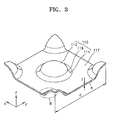
- FIG. 3 is a perspective view illustrating a portion of the pouch 110 depicted in FIG. 2
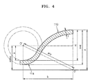
- FIG. 4 is a cross-sectional view illustrating a region B in FIG. 3 .
- the size and arrangement of protrusions 116 of the pouch 110 will now be described in detail with reference to FIGS. 3 and 4 .
- the pouch 110 may include: the first sealing material 111 covering a surface of the electrode assembly 130; and the second sealing material 112 covering an opposite surface of the electrode assembly 130 and connected to the first sealing material 111.
- the protrusions 116 may be formed on one or more of the first sealing material 111 and the second sealing material 112. One or more protrusions 116 may be formed.
- the following description is presented under the assumption that each of the first and second sealing materials 111 and 112 includes a plurality of protrusions 116.
- Each of the protrusions 116 may include a first curved portion 113 protruding outward from the pouch 110 and a second curved portion 114 formed along the edge of the first curved portion 113.
- a curvature change portion 115 may be formed between the first curved portion 113 and the second curved portion 114.
- the pouch 110 may include a base portion 117 among the protrusions 116.
- the pouch 110 may include pattern units U as shown in FIG. 2 .
- Each of the pattern units U may include a protrusion 116, sub-protrusions formed close to the protrusion 116, and the base portion 117 formed among the sub-protrusions.
- the sub-protrusions are portions of protrusions 116. In other words, in combinations of the pattern units U, sub-protrusions combining with other sub-protrusions may form protrusions 116.
- Each of the pattern units U may include four sub-protrusions located close to a central protrusion 116.
- the sub-protrusions are substantially equal to the quadrisections of one protrusion 116. Therefore, if four pattern units U are combined, a protrusion 116 may be formed by a combination of sub-protrusions. Thus, the following description will be primarily directed to the protrusions 116.
- the first curved portion 113 may have a convex shape
- the second curved portion 114 may have a concave shape.
- the second curved portion 114 may be separate from the center (O) of the first curved portion 113 by a constant distance and may fully surround the first curved portion 113.
- the radius of curvature (y) of the first curved portion 113 may be greater than the radius of curvature (x) of the second curved portion 114.
- Formula 1 for calculating the radius of curvature (y) of the first curved portion 113 and the radius of curvature (x) of the second curved portion 114 may be derived as follows.
- O denotes the center of curvature of the first curved portion 113
- O' denotes the center of curvature of the second curved portion 114
- t denotes the thickness of the pouch 110
- x denotes the radius of curvature of the second curved portion 114
- y denotes the radius of curvature of the first curved portion 113.
- b refers to the radius of the protrusion 116, which is a distance from the center of the first curved portion 113 to an edge of the second curved portion 114.
- the first equation of Formula 1 may be derived using the Pythagorean theorem.
- the second equation of Formula 1 may be derived from a length relationship
- the third equation of Formula 1 may be derived by combining the first and second equations.
- the thickness (t) of the pouch 110 may range from about 0.05 mm to about 0.1 mm. If the thickness (t) of the pouch 110 is less than about 0.05 mm, the pouch 110 may easily be deformed or broken, and the electrolyte contained inside the pouch 110 may leak. In contrast, if the thickness (t) of the pouch 110 is greater than about 0.1 mm, the flexibility of the pouch 110 may be low, and thus, it may be difficult to form the protrusions 116 on the pouch 110.
- the radius (b) of the protrusions 116 may range from about 0.05 mm to about 1.8 mm. If the radius (b) of the protrusions 116 is less than about 0.05 mm, the height (H) of the protrusions 116 is not sufficiently large, and thus the amount of deformation of the pouch 110, caused by the formation of the protrusions 116, may be insufficient. If the radius (b) of the protrusions 116 is greater than about 1.8 mm, the number of protrusions 116 per unit area is reduced, and thus the amount of deformation of the pouch 110, caused by the formation of the protrusions 116, may be insufficient.
- the height (H) of the protrusions 116 may range from about 0.05 mm to about 1.0 mm. If the height (H) of the protrusions 116 is less than about 0.05 mm, the amount of deformation of the pouch 110, caused by the formation of the protrusions 116, may be insufficient, and thus when the pouch 110 is bent, stress may not be effectively distributed (described later in more detail). If the height (H) of the protrusions 116 is greater than about 1.0 mm, the amount of deformation of the pouch 110, caused by the formation of the protrusions 116, may be excessive, and thus the strength of the pouch 110 may be decreased. In addition, since the volume of the pouch 110 increases in proportion to the height (H) of the protrusions 116, the pouch 110 may not be easily disposed in an electronic device, and the spatial efficiency of the pouch 110 may be lowered.
- the radius of curvature (y) of the first curved portion 113 of each protrusion 116 may be adjusted to be within the range of about 0.1 mm to about 24.05 mm according to the thickness (t) of the pouch 110 and the height (H) and radius (b) of the protrusions 116.
- the ratio of the vertical cross-sectional area to the surface area of the protrusions 116 may be greater than about 1:1 but less than about 1:3.
- the protrusions 116 are formed in accordance with the above-described ranges of the thickness (t) of the pouch 110, the height (H) and radius (b) of the protrusions 116, the number of the protrusions 116 per unit area (1 cm2) of the pouch 110 may be about 5 to about 125.
- first, second, and third directions are referred as first, second, and third directions, respectively.
- Each of the pattern units U has a cross-section (e) perpendicular to the first direction and parallel to the second and third directions.
- the length (second-direction length) of the cross-section (e) measured in the second direction may be longer than a unit length (d) of the pattern unit U.
- the second-direction length of the cross-section (e) may vary along the first direction.
- a pattern unit U was divided into ten parts in the first direction to calculate variations of the second-direction length of the cross-section (e) and resulting strain levels.
- the unit length (d) of the pattern unit U was 3.0 mm
- the thickness (t) of the pouch 110 was 0.07 mm
- the height (H) of the protrusions 116 was 0.3 mm.
- the second-direction length of the cross-section (e) is 3.0759 mm on average. In other words, the second-direction length of the cross-section (e) is greater than the unit length (d) by 2.53% on average.
- pattern units U were each divided into ten parts in the first direction to calculate variations of the second-direction length of the cross-section (e) according to variations of the height (H) of the protrusions 116.
- strain levels were calculated according to the variations of the second-distance length of the cross-section (e).
- the unit length (d) of the pattern units U was 3.0 mm
- the thickness (t) of the pouch 110 was 0.07 mm
- the height (H) of the protrusions 116 was varied to be 0.3 mm, 0.4 mm, and 0.5 mm.
- the strain of the pattern units U increases in proportion to the height (H) of the protrusions 116. If the height (H) of the protrusions 116 increases, the strain of the second-direction length of the cross-section (e) increases.
- a bending reliability test is performed. In the test, pouches of flexible secondary batteries were repeatedly subjected to a bending force to check whether the flexible secondary batteries were damaged or broken. In addition, when a force is applied to a flexible secondary battery to place the flexible secondary battery in an installation space by bending the flexible secondary battery, a pouch of the flexible secondary battery may be damaged or broken.
- FIG. 5 is a strain-curvature graph of flexible secondary batteries.
- Electrode assemblies each having a length of 110 mm were used in a test performed to plot the strain-curvature graph of FIG. 5 .
- the thicknesses of the electrode assemblies were 0.5 mm, 0.8 mm, 1.10 mm, and 1.35 mm, respectively, and the electrode assemblies were bent to radii of curvature of 25 mm, 40 mm, 100 mm, and 200 mm, respectively.
- strain levels of the electrode assemblies were calculated according to the radii of curvature. If an electrode assembly is bent to have a certain radius of curvature, a portion of the electrode assembly is stretched into a convex shape, and the other portion of the electrode assembly is compressed into a concave shape. Therefore, the strain of the electrode assembly indicates the degree of expansion or compression of the electrode assembly in the length direction thereof.
- S % t 2 R ⁇ 100
- S refers to the strain of an electrode assembly
- t refers to the thickness of the electrode assembly
- R refers to the radius of curvature of the electrode assembly.
- a portion of the electrode assembly When an electrode assembly having a length of 110 mm along a thickness centerline is bent, a portion of the electrode assembly may be stretched into a convex shape to have tensile strain, and the other portion of the electrode assembly may be compressed into a concave shape to have compressive strain.
- the pouch 110 of the flexible secondary battery 100 covers outer sides of the flexible secondary battery 100, if the electrode assembly 130 is bent to a radius of curvature as shown in FIG. 5 , the pouch 110 receives substantially the same bending force as that the electrode assembly 130 receives. If data shown in Tables 1 and 2 and FIG. 5 is compared and analyzed, the following conclusion may be obtained.
- the protrusions 116 are formed on the pouch 110, at least portions of the pouch 110 are deformed with a first strain. Then, if the electrode assembly 130 is bent, the electrode assembly 130 is stretched and compressed with a second strain.
- the pouch 110 may not be permanently deformed or broken even though an external force is applied to the flexible secondary battery 100. In other words, permanent deformation or breakage of the flexible secondary battery 100 caused by an external force applied thereto may be minimized, and thus the durability of the flexible secondary battery 100 may be improved.
- the secondary battery may be deformed with a strain of 2.2%. Thereafter, although the secondary battery is returned to an original shape thereof by resilience or elasticity, the rigidity of the secondary battery may be reduced, and the secondary battery may be cracked or torn.
- the pouch 110 has a thickness of 0.07 mm, and the protrusions 116 of the pouch 110 have a height (H) of 0.3 mm.
- the pouch 110 covers an electrode assembly 130 having a thickness (t) of 1.1 mm, although the electrode assembly 130 is bent to a radius of curvature of 25 mm or greater, the pouch 110 may not be permanently deformed.
- the pouch 110 has a thickness of 0.07 mm, and the protrusions 116 of the pouch 110 have a height (H) of 0.4 mm.
- the pouch 110 covers an electrode assembly 130 having a thickness (t) of 1.35 mm, although the electrode assembly 130 is bent to a radius of curvature of 25 mm or greater, the pouch 110 may not be permanently deformed.
- the deformation of the pouch 110 may be prevented within the certain degree of strain previously given to the pouch 110. That is, the degree of strain previously given to the pouch 110 by the formation of the protrusions 116 is adjusted to be greater than a degree of strain of the electrode assembly 130 when the flexible secondary battery 100 in which the electrode assembly 130 and the pouch 110 are coupled is deformed by a force applied thereto. Therefore, although an external force is applied to the flexible secondary battery 100, the pouch 110 may not be permanently deformed or damaged.
- the external force When an external force is applied to the flexible secondary battery 100, the external force may be distributed to the protrusions 116 of the pouch 110, and thus the durability of the pouch 110 may be improved.
- the pouch 110 When an external force is applied to the flexible secondary battery 100, the pouch 110 may be flexibly deformed while the protrusions 116 and the base portion 117 formed between the protrusions 116 are stretched or compressed. Therefore, although an external force is applied to the flexible secondary battery 100, the pouch 110 may not be permanently deformed or damaged.
- the pouch 110 used as a sealing material for the flexible secondary battery 100 includes the protrusions 116, stress caused by an external force may be distributed to the protrusions 116. Therefore, the durability of the flexible secondary battery 100 may be improved.
- the second curved portions 114 are formed in the protrusions 116 so that the protrusions 116 may have a gentle curvature, and thus the pouch 110 of the flexible secondary battery 100 may be less cracked or torn.
- the stability of the flexible secondary battery 100 may be maintained when the flexible secondary battery 100 is repeatedly flexed or bent.
Landscapes
- Chemical & Material Sciences (AREA)
- Chemical Kinetics & Catalysis (AREA)
- Electrochemistry (AREA)
- General Chemical & Material Sciences (AREA)
- Engineering & Computer Science (AREA)
- Manufacturing & Machinery (AREA)
- Materials Engineering (AREA)
- Sealing Battery Cases Or Jackets (AREA)
- Secondary Cells (AREA)
Abstract
Description
- The present invention relates to a flexible secondary battery.
- Along with the development of electronics, markets for cellular phones, portable multimedia players (PMPs), and mpeg audio layer-3 (MP3) players, as well as markets for other various portable electronic devices such as smartphones, smart pads, electronic book readers, flexible tablet computers, and portable medical devices attachable to the human body have grown markedly.
- The growth of markets for such portable electronic devices has increased the demand for batteries suitable for operating such portable electronic devices. In addition, such portable electronic devices are increasingly required to be flexible to endure transportation, storage, and impact, and thus the demand for flexible batteries has also increased.
- One or more exemplary embodiments include a flexible secondary battery which is stable even when repeatedly flexed or bent.
- Additional aspects will be set forth in part in the description which follows and, in part, will be apparent from the description, or may be learned by practice of the presented embodiments.
- According to one or more exemplary embodiments, a flexible secondary battery includes: an electrode assembly including a first electrode plate, a second electrode plate, and a separator between the first and second electrode plates; and a pouch including a plurality of outwardly extending protrusions and sealing the electrode assembly and an electrolyte therein, wherein a degree of strain of the electrode assembly resulting from bending of the pouch is lower than a degree of strain given to the pouch by formation of the protrusions.
- A flat base portion may be formed between the protrusions.
- Each of the protrusions may include: a first curved portion protruding outward; and a second curved portion formed along an edge of the first curved portion.
- The second curved portion may be separate from a center of the first curved portion by a constant distance and may completely surround the first curved portion.
- The first curved portion may be convex, and the second curved portion may be concave.
- The first curved portion may have a greater radius of curvature than a radius of curvature of the second curved portion.
- The first curved portion and the second curved portion may have radii of curvature satisfying the following formula:


- The pouch may have a thickness of about 0.05 mm to about 0.1 mm.
- The radius of each of the protrusions may range from about 0.05 mm to about 1.8 mm.
- The height of each of the protrusions may range from about 0.05 mm to about 1.0 mm.
- A ratio of the vertical cross-sectional area to the surface area of each of the protrusions may be greater than about 1:1 but less than about 1:3.
- The number of protrusions per unit area (1 cm2) of the pouch may be about 5 to about 125.
- The flexible secondary battery may further include: a first electrode tab connected to the first electrode plate; and a second electrode tab connected to the second electrode plate.
- According to one or more exemplary embodiments, a flexible secondary battery includes: an electrode assembly including a first electrode plate, a second electrode plate, and a separator between the first and second electrode plates; and a pouch including an outwardly protruding pattern unit and sealing the electrode assembly and an electrolyte therein, wherein the pattern unit includes: a protrusion; a sub-protrusion disposed close to the protrusion; and a base portion disposed between the protrusion and the sub-protrusion.
- The protrusion may include: a first curved portion protruding outward; and a second curved portion formed outside the first curved portion and connected to the base portion.
- The second curved portion may be separate from a center of the first curved portion by a constant distance and may fully surround the first curved portion.
- The first curved portion may be convex, and the second curved portion may be concave.
- The first curved portion may have a greater radius of curvature than a radius of curvature of the second curved portion.
- The pattern unit may have a first direction, a second direction perpendicular to the first direction, and a third direction perpendicular to the first and second directions, and the protrusion may protrude in the third direction, wherein the pattern unit may have a cross-section perpendicular to the first direction and parallel to the second and third directions, wherein the cross-section may have a second-direction length that is longer than a second-direction unit length of the pattern unit.
- The second-direction length of the cross-section of the pattern unit may vary along the first direction.
- The first curved portion and the second curved portion may have radii of curvature satisfying the following formula:


- These and/or other aspects will become apparent and more readily appreciated from the following description of the exemplary embodiments, taken in conjunction with the accompanying drawings in which:
-
FIG. 1 is an exploded perspective view schematically illustrating a flexible secondary battery according to an exemplary embodiment; -
Fig. 2 is a plan view illustrating the flexible secondary battery depicted inFig. 1 ; -
FIG. 3 is a perspective view illustrating a portion of a pouch depicted inFIG. 2 ; -
FIG. 4 is a cross-sectional view illustrating a region B inFIG. 3 ; and -
FIG. 5 is a strain-curvature graph of flexible secondary batteries. - In the following description of exemplary embodiments, the directions of a flexible
secondary battery 100 are defined for clarity in illustration as follows: the length direction of the flexiblesecondary battery 100 is defined as an x-axis direction, the width direction of the flexiblesecondary battery 100 is defined as a y-axis direction, and the thickness direction of the flexiblesecondary battery 100 is defined as a z-axis direction. -
FIG. 1 is an exploded perspective view schematically illustrating the flexiblesecondary battery 100 according to an exemplary embodiment, andFIG. 2 is a plan view illustrating the flexiblesecondary battery 100 depicted inFIG. 1 . - Referring to
FIGS. 1 and2 , the flexiblesecondary battery 100 may include apouch 110, anelectrode assembly 130, andelectrode tabs 150 such as first andsecond electrode tabs - The
pouch 110 may accommodate theelectrode assembly 130 together with an electrolyte and seal theelectrode assembly 130 and the electrolyte. Thepouch 110 may be flexible and prevent permeation of moisture or oxygen into the flexiblesecondary battery 100. Thepouch 110 may include: afirst sealing material 111 covering a surface of theelectrode assembly 130; and asecond sealing material 112 covering an opposite surface of theelectrode assembly 130 and connected to thefirst sealing material 111. - The
pouch 110 may have a stacked structure formed by an insulation layer, a barrier layer, and an insulation layer. For example, thepouch 110 may be formed by sequentially stacking insulation and barrier layers. Thepouch 110 may include a plurality of barrier layers, and the barrier layers may have different thicknesses. - For example, a first barrier layer formed at a side of the
pouch 110 may be thinner than a second barrier layer facing the first barrier layer. When thepouch 110 is formed in a curved shape, elongation of thepouch 110 increases in a direction away from the center of curvature of the curved shape. For example, the first barrier layer of thepouch 110, relatively distant from the center of curvature of the curved shape, may be easily elongated, compared to the second barrier layer. Therefore, the breakage or deformation of thepouch 110 may be minimized, and the durability of thepouch 110 may be improved. - In addition, the first barrier layer of the
pouch 110 may be formed of a material having a relatively high degree of elongation, and the second barrier layer of thepouch 110 may be formed of a material having a relatively low degree of elongation compared to the first barrier layer. In this case, when thepouch 110 is formed in a curve shape, the first barrier layer of thepouch 110, relatively distant from the center of curvature of the curved shape, may be easily elongated, compared to the second barrier layer. Therefore, the breakage or deformation of thepouch 110 may be minimized, and the durability of thepouch 110 may be improved. - The barrier layers may be formed of a material such as aluminum, steel, stainless steel, or a polymer, and the insulation layers may be formed of a material such as chlorinated polypropylene (CPP), polyethylene terephthalate (PET), or nylon. However, the barrier layers and the insulation layers are not limited thereto.
- The
electrode assembly 130 may include afirst electrode layer 131, asecond electrode layer 132, and aseparator 133 located between thefirst electrode layer 131 and thesecond electrode layer 132. Theelectrode assembly 130 may be formed by repeatedly stacking thefirst electrode layer 131, theseparator 133, and thesecond electrode layer 132, or rolling thefirst electrode layer 131, theseparator 133, and thesecond electrode layer 132 in the form of a jelly roll. For ease of description, the case in which theelectrode assembly 130 has a stacked structure formed by thefirst electrode layer 131, theseparator 133, and thesecond electrode layer 132 will be primarily described in detail. - The
first electrode layer 131 may be one of a positive electrode film and a negative electrode film. If thefirst electrode layer 131 is a positive electrode film, thesecond electrode layer 132 may be a negative electrode film. On the other hand, if thefirst electrode layer 131 is a negative electrode film, thesecond electrode layer 132 may be a positive electrode film. - The
first electrode layer 131 may include a first metal collector, a first active material-coated portion formed by coating the first metal collector with a first active material, and a first non-coated portion which is a portion of the first metal collector that is not coated with the first active material. Similarly, thesecond electrode layer 132 may include a second metal collector, a second active material-coated portion 124 formed by coating the second metal collector with a second active material, and a second non-coated portion which is a portion of the second metal collector that is not coated with the second active material. - If the
first electrode layer 131 is a positive electrode film, the first metal collector may be a positive electrode collector, and the first active material-coated portion may be a positive electrode active material-coated portion. If thesecond electrode layer 132 is a negative electrode film, the second metal collector may be a negative electrode collector, and the second active material-coated portion may be a negative electrode active material-coated portion. - The positive electrode collector may be a metal collector formed of aluminum, stainless steel, titanium, copper, silver, or a combination thereof. The positive electrode active material-coated portion may include a positive electrode active material, a binder, and a conducting agent.
- The positive electrode active material may be a material capable of reversibly intercalating and deintercalating lithium ions. For example, the positive electrode active material includes at least one material selected from the group consisting of lithium transition metal oxides such as lithium cobalt oxide, lithium nickel oxide, lithium nickel cobalt oxide, lithium nickel cobalt aluminum oxide, lithium nickel cobalt manganese oxide, lithium manganese oxide, and lithium iron phosphate; nickel sulfides; copper sulfides; sulfur; iron oxides; and vanadium oxides.
- The binder may include at least one material selected from the group consisting of polyvinylidene fluoride-containing binders such as polyvinylidene fluoride, vinylidene fluoride/hexafluoropropylene copolymer, and vinylidene fluoride/tetrafluroethylene copolymer; carboxymethyl cellulose-containing binders such as sodium-carboxymethyl cellulose and lithium-carboxymethyl cellulose; acrylate-containing binders such as polyacrylic acid, lithium-polyacrylic acid, acrylic, polyacrylonitrile, polymethyl methacrylate, and poly(butyl acrylate); polyamide-imides; polytetrafluoroethylene; polyethylene oxide; polypyrrole; lithium-Nafion; and styrene butadiene rubber-containing polymers.
- The conducting agent may include at least one material selected from the group consisting of carbon-containing conducting agents such as carbon black, carbon fiber, and graphite; conductive fiber such as metal fiber; metal powder such as carbon fluoride powder, aluminum powder, and nickel powder; conductive whisker such as zinc oxides and potassium titanate; conductive metal oxides such as titanium oxides; and conductive polymers such as polyphenylene derivatives.
- The negative electrode collector may include at least one metal selected from the group consisting of copper, stainless steel, nickel, aluminum, and titanium. The negative electrode active material-coated portion may include a negative electrode active material, a binder, and a conducting agent.
- The negative electrode active material may be a material capable of forming an alloy together with lithium or capable of reversibly intercalating and deintercalating lithium. For example, the negative electrode active material may be include at least one material selected from the group consisting of metals, carbon-containing materials, metal oxides, and lithium metal nitrides.
- The metals may include at least one selected from the group consisting of lithium, silicon, magnesium, calcium, aluminum, germanium, tin, lead, arsenic, antimony, bismuth, silver, gold, zinc, cadmium, mercury, copper, iron, nickel, cobalt, and indium.
- The carbon-containing materials may include at least one material selected from the group consisting of graphite, graphite carbon fiber, coke, mesocarbon microbeads (MCMBs), polyacene, pitch-derived carbon fiber, and hard carbon.
- The metal oxides may include at least one selected from the group consisting of lithium titanium oxides, titanium oxides, molybdenum oxides, niobium oxides, iron oxides, tungsten oxides, tin oxides, amorphous tin oxide composites, silicon monoxide, cobalt oxides, and nickel oxides.
- The binder and the conducting agent may be the same as the binder and the conducting agent included in the positive electrode active material.
- The positive electrode film and the negative electrode film may be formed by applying active materials to metal collectors by various methods. That is, methods of applying electrode active materials are not limited.
- The
separator 133 may be a porous polymer film such as a polyethylene film or a polyprophylene film. Theseparator 133 may be woven fabric or non-woven fabric including polymer fabric. Theseparator 130 may include ceramic particles and may be formed of solid polymer electrolyte. Theseparator 133 may be an independent film or may be a porous layer formed on thefirst electrode layer 131 or thesecond electrode layer 132. - The
separator 133 electrically separates thefirst electrode layer 131 and thesecond electrode layer 132 from each other, and theseparator 133 is not required to have the same shape as the shape of thefirst electrode layer 131 or thesecond electrode layer 132. - The
electrode tabs 150 may be connected to theelectrode assembly 130 for electric connection with an external device. Thefirst electrode layer 131 is electrically connected to thefirst electrode tab 151, and thesecond electrode layer 132 is electrically connected to thesecond electrode tab 152. Thefirst electrode tab 151 may include afirst insulator 153, and thesecond electrode tab 152 may include asecond insulator 154, so as to prevent a short circuit between the first and second electrode layers 131 and 132. Materials that may be used to form thefirst insulator 153 and thesecond insulator 154 are not limited as long as the materials are insulative. -
FIG. 3 is a perspective view illustrating a portion of thepouch 110 depicted inFIG. 2 , andFIG. 4 is a cross-sectional view illustrating a region B inFIG. 3 . The size and arrangement ofprotrusions 116 of thepouch 110 will now be described in detail with reference toFIGS. 3 and4 . - As described above, the
pouch 110 may include: thefirst sealing material 111 covering a surface of theelectrode assembly 130; and thesecond sealing material 112 covering an opposite surface of theelectrode assembly 130 and connected to thefirst sealing material 111. Theprotrusions 116 may be formed on one or more of thefirst sealing material 111 and thesecond sealing material 112. One ormore protrusions 116 may be formed. For ease of description, the following description is presented under the assumption that each of the first andsecond sealing materials protrusions 116. - Each of the
protrusions 116 may include a firstcurved portion 113 protruding outward from thepouch 110 and a secondcurved portion 114 formed along the edge of the firstcurved portion 113. Acurvature change portion 115 may be formed between the firstcurved portion 113 and the secondcurved portion 114. Thepouch 110 may include abase portion 117 among theprotrusions 116. - The
pouch 110 may include pattern units U as shown inFIG. 2 . Each of the pattern units U may include aprotrusion 116, sub-protrusions formed close to theprotrusion 116, and thebase portion 117 formed among the sub-protrusions. The sub-protrusions are portions ofprotrusions 116. In other words, in combinations of the pattern units U, sub-protrusions combining with other sub-protrusions may formprotrusions 116. - Each of the pattern units U may include four sub-protrusions located close to a
central protrusion 116. In one embodiment, the sub-protrusions are substantially equal to the quadrisections of oneprotrusion 116. Therefore, if four pattern units U are combined, aprotrusion 116 may be formed by a combination of sub-protrusions. Thus, the following description will be primarily directed to theprotrusions 116. - In each of the
protrusions 116, the firstcurved portion 113 may have a convex shape, and the secondcurved portion 114 may have a concave shape. The secondcurved portion 114 may be separate from the center (O) of the firstcurved portion 113 by a constant distance and may fully surround the firstcurved portion 113. The radius of curvature (y) of the firstcurved portion 113 may be greater than the radius of curvature (x) of the secondcurved portion 114. - Referring to
FIG. 4 , Formula 1 for calculating the radius of curvature (y) of the firstcurved portion 113 and the radius of curvature (x) of the secondcurved portion 114 may be derived as follows.
- In
FIG. 4 , O denotes the center of curvature of the firstcurved portion 113, O' denotes the center of curvature of the secondcurved portion 114, t denotes the thickness of thepouch 110, x denotes the radius of curvature of the secondcurved portion 114, and y denotes the radius of curvature of the firstcurved portion 113. Further, b refers to the radius of theprotrusion 116, which is a distance from the center of the firstcurved portion 113 to an edge of the secondcurved portion 114. H refers to the height of theprotrusion 116, which is a distance from a surface of thebase portion 117 to the apex of the firstcurved portion 113 while a refers to a value calculated by subtracting the height (H) of theprotrusion 116 and the thickness (t) of thepouch 110 from the radius of curvature (y) of the first curved portion 113 (a = y-H-t). - Referring to
FIG. 4 , the first equation of Formula 1 may be derived using the Pythagorean theorem. In addition, the second equation of Formula 1 may be derived from a length relationship, and the third equation of Formula 1 may be derived by combining the first and second equations. - The thickness (t) of the
pouch 110 may range from about 0.05 mm to about 0.1 mm. If the thickness (t) of thepouch 110 is less than about 0.05 mm, thepouch 110 may easily be deformed or broken, and the electrolyte contained inside thepouch 110 may leak. In contrast, if the thickness (t) of thepouch 110 is greater than about 0.1 mm, the flexibility of thepouch 110 may be low, and thus, it may be difficult to form theprotrusions 116 on thepouch 110. - The radius (b) of the
protrusions 116 may range from about 0.05 mm to about 1.8 mm. If the radius (b) of theprotrusions 116 is less than about 0.05 mm, the height (H) of theprotrusions 116 is not sufficiently large, and thus the amount of deformation of thepouch 110, caused by the formation of theprotrusions 116, may be insufficient. If the radius (b) of theprotrusions 116 is greater than about 1.8 mm, the number ofprotrusions 116 per unit area is reduced, and thus the amount of deformation of thepouch 110, caused by the formation of theprotrusions 116, may be insufficient. If the amount of deformation of thepouch 110, caused by the formation of theprotrusions 116, is insufficient, when thepouch 110 is bent, stress may not be effectively distributed in the pouch 110 (described later in more detail), and thus concentration of stress may not be effectively prevented. - The height (H) of the
protrusions 116 may range from about 0.05 mm to about 1.0 mm. If the height (H) of theprotrusions 116 is less than about 0.05 mm, the amount of deformation of thepouch 110, caused by the formation of theprotrusions 116, may be insufficient, and thus when thepouch 110 is bent, stress may not be effectively distributed (described later in more detail). If the height (H) of theprotrusions 116 is greater than about 1.0 mm, the amount of deformation of thepouch 110, caused by the formation of theprotrusions 116, may be excessive, and thus the strength of thepouch 110 may be decreased. In addition, since the volume of thepouch 110 increases in proportion to the height (H) of theprotrusions 116, thepouch 110 may not be easily disposed in an electronic device, and the spatial efficiency of thepouch 110 may be lowered. - The radius of curvature (y) of the first
curved portion 113 of eachprotrusion 116 may be adjusted to be within the range of about 0.1 mm to about 24.05 mm according to the thickness (t) of thepouch 110 and the height (H) and radius (b) of theprotrusions 116. In addition, the radius of curvature (x) of the secondcurved portion 114 of eachprotrusion 116 may range from about 0.0 mm to about 23.95 mm. If the secondcurved portion 114 is not formed (x=o), a time necessary to form thepouch 110 may be reduced owing to omission of the secondcurved portion 114. - If the
protrusions 116 are formed in accordance with the above-described ranges of the thickness (t) of thepouch 110, the height (H) and radius (b) of theprotrusions 116, the ratio of the vertical cross-sectional area to the surface area of theprotrusions 116 may be greater than about 1:1 but less than about 1:3. The vertical cross-sectional area of eachprotrusion 116 may be expressed as the product of the square of the radius (b) of theprotrusion 116 and π (i.e., vertical cross-sectional area = πb2), and the surface area of eachprotrusion 116 may be expressed as the sum of the surface area of the firstcurved portion 113 and the surface area of the secondcurved portion 114. - If the
protrusions 116 are formed in accordance with the above-described ranges of the thickness (t) of thepouch 110, the height (H) and radius (b) of theprotrusions 116, the number of theprotrusions 116 per unit area (1 cm2) of thepouch 110 may be about 5 to about 125. - The amount of deformation of the pattern units U will now be described according to the formation of the
protrusions 116 with reference toFIG. 3 . Portions of thepouch 110 are the same as the pattern units U. Hereinafter, the x-axis, y-axis, and z-axis directions will be referred as first, second, and third directions, respectively. - Each of the pattern units U has a cross-section (e) perpendicular to the first direction and parallel to the second and third directions. The length (second-direction length) of the cross-section (e) measured in the second direction may be longer than a unit length (d) of the pattern unit U. In addition, the second-direction length of the cross-section (e) may vary along the first direction.
- As shown in Table 1 below, a pattern unit U was divided into ten parts in the first direction to calculate variations of the second-direction length of the cross-section (e) and resulting strain levels. In the measurement, the unit length (d) of the pattern unit U was 3.0 mm, the thickness (t) of the
pouch 110 was 0.07 mm, and the height (H) of theprotrusions 116 was 0.3 mm.Table 1 Dividing positions (mm) Second-direction length (mm) Ratio (%) Strain (%) 0.0 3.1439 104.80 4.80 0.3 3.0965 103.22 3.22 0.6 3.0037 100.12 0.12 0.9 3.0050 100.17 0.17 1.2 3.0965 103.22 3.22 1.5 3.1439 104.80 4.80 1.8 3.0965 103.22 3.22 2.1 3.0050 100.17 0.17 2.4 3.0037 100.12 0.12 2.7 3.0965 103.22 3.22 3.0 3.1439 104.80 4.80 Average 3.0759 102.53 2.53 - Referring to Table 1, although the unit length (d) of the pattern unit U on which the
protrusions 116 are formed is 3.0 mm, the second-direction length of the cross-section (e) is 3.0759 mm on average. In other words, the second-direction length of the cross-section (e) is greater than the unit length (d) by 2.53% on average. - As shown in Table 2 below, pattern units U were each divided into ten parts in the first direction to calculate variations of the second-direction length of the cross-section (e) according to variations of the height (H) of the
protrusions 116. In addition, strain levels were calculated according to the variations of the second-distance length of the cross-section (e). When the strain levels of the second-direction length of the cross-section (e) were calculated, the unit length (d) of the pattern units U was 3.0 mm, the thickness (t) of thepouch 110 was 0.07 mm, and the height (H) of theprotrusions 116 was varied to be 0.3 mm, 0.4 mm, and 0.5 mm.Table 2 Dividing positions (mm) Strain (%) 0.3mm 0.4mm 0.5mm 0.0 4.7967 8.4867 12.9533 0.3 3.2167 6.4533 10.3000 0.6 0.1233 0.5367 0.8667 0.9 0.1667 0.5367 0.8700 1.2 3.2167 6.4533 10.3000 1.5 4.7967 8.4867 12.9533 1.8 3.2167 5.4533 10.3000 2.1 0.1667 0.5367 0.8700 2.4 0.1233 0.5367 0.8667 2.7 3.2167 6.4533 10.3000 3.0 4.7967 8.4867 12.9533 Average 2.53 4.77 7.59 - Referring to Table 2, the strain of the pattern units U increases in proportion to the height (H) of the
protrusions 116. If the height (H) of theprotrusions 116 increases, the strain of the second-direction length of the cross-section (e) increases. - With the advance of electronic technology, the electronic device market has increased, and thus demand for batteries for electronic devices has increased. Particularly, demand for flexible secondary batteries having a high degree of efficiency in utilization of space has increased in various application fields.
- When flexible secondary batteries are manufactured, a bending reliability test is performed. In the test, pouches of flexible secondary batteries were repeatedly subjected to a bending force to check whether the flexible secondary batteries were damaged or broken. In addition, when a force is applied to a flexible secondary battery to place the flexible secondary battery in an installation space by bending the flexible secondary battery, a pouch of the flexible secondary battery may be damaged or broken.
-
FIG. 5 is a strain-curvature graph of flexible secondary batteries. - Electrode assemblies each having a length of 110 mm were used in a test performed to plot the strain-curvature graph of
FIG. 5 . The thicknesses of the electrode assemblies were 0.5 mm, 0.8 mm, 1.10 mm, and 1.35 mm, respectively, and the electrode assemblies were bent to radii of curvature of 25 mm, 40 mm, 100 mm, and 200 mm, respectively. Then, strain levels of the electrode assemblies were calculated according to the radii of curvature. If an electrode assembly is bent to have a certain radius of curvature, a portion of the electrode assembly is stretched into a convex shape, and the other portion of the electrode assembly is compressed into a concave shape. Therefore, the strain of the electrode assembly indicates the degree of expansion or compression of the electrode assembly in the length direction thereof.
- In Formula 2, S refers to the strain of an electrode assembly, t refers to the thickness of the electrode assembly, and R refers to the radius of curvature of the electrode assembly.
- When an electrode assembly having a length of 110 mm along a thickness centerline is bent, a portion of the electrode assembly may be stretched into a convex shape to have tensile strain, and the other portion of the electrode assembly may be compressed into a concave shape to have compressive strain.
- Since the
pouch 110 of the flexiblesecondary battery 100 covers outer sides of the flexiblesecondary battery 100, if theelectrode assembly 130 is bent to a radius of curvature as shown inFIG. 5 , thepouch 110 receives substantially the same bending force as that theelectrode assembly 130 receives. If data shown in Tables 1 and 2 andFIG. 5 is compared and analyzed, the following conclusion may be obtained. When theprotrusions 116 are formed on thepouch 110, at least portions of thepouch 110 are deformed with a first strain. Then, if theelectrode assembly 130 is bent, theelectrode assembly 130 is stretched and compressed with a second strain. In this case, if theelectrode assembly 130 is bent within a range in which the second strain is less than the first strain, thepouch 110 may not be permanently deformed or broken even though an external force is applied to the flexiblesecondary battery 100. In other words, permanent deformation or breakage of the flexiblesecondary battery 100 caused by an external force applied thereto may be minimized, and thus the durability of the flexiblesecondary battery 100 may be improved. - For example, if a secondary battery having a thickness (t) of 1.1 mm and not including
protrusions 116 is bent to a radius of curvature of 25 mm, the secondary battery may be deformed with a strain of 2.2%. Thereafter, although the secondary battery is returned to an original shape thereof by resilience or elasticity, the rigidity of the secondary battery may be reduced, and the secondary battery may be cracked or torn. - In the case of Table 1, the
pouch 110 has a thickness of 0.07 mm, and theprotrusions 116 of thepouch 110 have a height (H) of 0.3 mm. In this case, if thepouch 110 covers anelectrode assembly 130 having a thickness (t) of 1.1 mm, although theelectrode assembly 130 is bent to a radius of curvature of 25 mm or greater, thepouch 110 may not be permanently deformed. - In the case of Table 2, the
pouch 110 has a thickness of 0.07 mm, and theprotrusions 116 of thepouch 110 have a height (H) of 0.4 mm. In this case, if thepouch 110 covers anelectrode assembly 130 having a thickness (t) of 1.35 mm, although theelectrode assembly 130 is bent to a radius of curvature of 25 mm or greater, thepouch 110 may not be permanently deformed. - In other words, since the
pouch 110 is previously deformed to have a certain degree of strain, the deformation of thepouch 110 may be prevented within the certain degree of strain previously given to thepouch 110. That is, the degree of strain previously given to thepouch 110 by the formation of theprotrusions 116 is adjusted to be greater than a degree of strain of theelectrode assembly 130 when the flexiblesecondary battery 100 in which theelectrode assembly 130 and thepouch 110 are coupled is deformed by a force applied thereto. Therefore, although an external force is applied to the flexiblesecondary battery 100, thepouch 110 may not be permanently deformed or damaged. - When an external force is applied to the flexible
secondary battery 100, the external force may be distributed to theprotrusions 116 of thepouch 110, and thus the durability of thepouch 110 may be improved. When an external force is applied to the flexiblesecondary battery 100, thepouch 110 may be flexibly deformed while theprotrusions 116 and thebase portion 117 formed between theprotrusions 116 are stretched or compressed. Therefore, although an external force is applied to the flexiblesecondary battery 100, thepouch 110 may not be permanently deformed or damaged. - Since the
pouch 110 used as a sealing material for the flexiblesecondary battery 100 includes theprotrusions 116, stress caused by an external force may be distributed to theprotrusions 116. Therefore, the durability of the flexiblesecondary battery 100 may be improved. - The second
curved portions 114 are formed in theprotrusions 116 so that theprotrusions 116 may have a gentle curvature, and thus thepouch 110 of the flexiblesecondary battery 100 may be less cracked or torn. - As described above, according to the one or more of the above exemplary embodiments, the stability of the flexible
secondary battery 100 may be maintained when the flexiblesecondary battery 100 is repeatedly flexed or bent. - Other effects of the exemplary embodiments may be understood from the above description with reference to the accompanying drawings.
- It should be understood that the exemplary embodiments described herein should be considered in a descriptive sense only and not for purposes of limitation. Descriptions of features or aspects within each exemplary embodiment should typically be considered as available for other similar features or aspects in other exemplary embodiments.
- While one or more exemplary embodiments have been described with reference to the figures, it will be understood by those of ordinary skill in the art that various changes in form and details may be made therein without departing from the scope of the invention as defined by the following claims.
Claims (15)
- A flexible secondary battery comprising:an electrode assembly comprising a first electrode plate, a second electrode plate, and a separator between the first and second electrode plates; anda pouch comprising a plurality of outwardly extending protrusions, the pouch sealing the electrode assembly and an electrolyte therein,wherein the pouch is configured such that the degree of strain of the electrode assembly resulting from predetermined bending of the pouch is lower than the degree of strain on the pouch resulting from formation of the protrusions.
- The flexible secondary battery of claim 1, wherein each of the protrusions comprises:a first curved portion protruding outward; anda second curved portion formed along an edge of the first curved portion.
- The flexible secondary battery of claim 2, wherein the second curved portion is spaced from a center of the first curved portion by a constant distance and entirely surrounds the first curved portion.
- The flexible secondary battery of claim 2 or 3, wherein the first curved portion is convex and the second curved portion is concave.
- The flexible secondary battery of claim 2, 3 or 4, wherein the first curved portion has a greater radius of curvature than the second curved portion.
- The flexible secondary battery of any one of claims 2 to 5, wherein the first curved portion and the second curved portion have radii of curvature satisfying the following formula:


- The flexible secondary battery of any one of the preceding claims, wherein the pouch has a thickness from about 0.05 mm to about 0.1 mm.
- The flexible secondary battery of any one of the preceding claims, wherein the radius of each of the protrusions ranges from about 0.05 mm to about 1.8 mm.
- The flexible secondary battery of any one of the preceding claims, wherein the height of each of the protrusions ranges from about 0.05 mm to about 1.0 mm.
- The flexible secondary battery of any one of the preceding claims, wherein a ratio of the vertical cross-sectional area to the surface area of each of the protrusions is greater than about 1:1 but less than about 1:3.
- The flexible secondary battery of any one of the preceding claims, wherein a number of protrusions per square centimeter of the pouch is about 5 to about 125.
- The flexible secondary battery of any one of the preceding claims further comprising:a first electrode tab connected to the first electrode plate; anda second electrode tab connected to the second electrode plate.
- The flexible secondary battery of any one of the preceding claims, wherein the pouch comprises a plurality of outwardly protruding pattern units, each of the pattern units comprising:a protrusion;a sub-protrusion close to the protrusion; anda base portion located between the protrusion and the sub-protrusion.
- The flexible secondary battery of claim 13, wherein the pattern unit extends in a first direction, in a second direction perpendicular to the first direction, and in a third direction perpendicular to the first and second directions, wherein the protrusion protrudes in the third direction,
wherein the pattern unit has a cross-section perpendicular to the first direction and parallel to the second and third directions, and
wherein the cross-section has a second-direction length that is longer than a second-direction unit length of the pattern unit. - The flexible secondary battery of claim 14, wherein the second-direction length of the cross-section of the pattern unit varies along the first direction.
Applications Claiming Priority (1)
| Application Number | Priority Date | Filing Date | Title |
|---|---|---|---|
| KR1020150022716A KR102381779B1 (en) | 2015-02-13 | 2015-02-13 | Flexible secondary battery |
Publications (2)
| Publication Number | Publication Date |
|---|---|
| EP3057153A1 true EP3057153A1 (en) | 2016-08-17 |
| EP3057153B1 EP3057153B1 (en) | 2020-01-01 |
Family
ID=55274988
Family Applications (1)
| Application Number | Title | Priority Date | Filing Date |
|---|---|---|---|
| EP16153353.4A Active EP3057153B1 (en) | 2015-02-13 | 2016-01-29 | Flexible secondary battery |
Country Status (5)
| Country | Link |
|---|---|
| US (1) | US10727452B2 (en) |
| EP (1) | EP3057153B1 (en) |
| JP (1) | JP6721229B2 (en) |
| KR (1) | KR102381779B1 (en) |
| CN (1) | CN105895832B (en) |
Cited By (3)
| Publication number | Priority date | Publication date | Assignee | Title |
|---|---|---|---|---|
| EP3309871A1 (en) * | 2016-10-14 | 2018-04-18 | Samsung Electronics Co., Ltd. | Electrode assembly, lithium ion battery and electronic device including the same |
| EP3629414A4 (en) * | 2017-06-17 | 2020-05-27 | Huawei Technologies Co. Ltd. | FLEXIBLE BATTERY AND MANUFACTURING METHOD THEREFOR |
| EP4601077A1 (en) * | 2024-02-07 | 2025-08-13 | SK On Co., Ltd. | Battery cell and battery device having the same |
Families Citing this family (7)
| Publication number | Priority date | Publication date | Assignee | Title |
|---|---|---|---|---|
| JP6484800B2 (en) * | 2015-02-24 | 2019-03-20 | パナソニックIpマネジメント株式会社 | Flexible battery |
| US10686167B2 (en) | 2015-07-31 | 2020-06-16 | Semiconductor Energy Laboratory Co., Ltd. | Power storage device, battery management unit, and electronic device |
| KR102349741B1 (en) * | 2017-05-30 | 2022-01-11 | 에스케이온 주식회사 | Lithium secondary battery |
| KR20200143952A (en) | 2019-06-17 | 2020-12-28 | 주식회사 리베스트 | Electrochemical cell and case provided therein |
| CN115066790B (en) * | 2020-02-20 | 2023-10-27 | 日本碍子株式会社 | Lithium ion secondary battery |
| JP7569496B2 (en) * | 2020-06-22 | 2024-10-18 | トヨタ自動車株式会社 | Sealed battery |
| CN120419021A (en) | 2022-12-22 | 2025-08-01 | 株式会社 Lg新能源 | Soft package type battery case and soft package type secondary battery |
Citations (3)
| Publication number | Priority date | Publication date | Assignee | Title |
|---|---|---|---|---|
| JP2000173559A (en) * | 1998-12-03 | 2000-06-23 | Tokai Rubber Ind Ltd | Thin battery bag |
| JP2009016275A (en) * | 2007-07-06 | 2009-01-22 | Nissan Motor Co Ltd | Secondary battery, assembled battery and vehicle |
| US20130101884A1 (en) * | 2011-04-11 | 2013-04-25 | Panasonic Corporation | Flexible battery and method for producing the same |
Family Cites Families (10)
| Publication number | Priority date | Publication date | Assignee | Title |
|---|---|---|---|---|
| JPS5147231B2 (en) * | 1971-08-25 | 1976-12-14 | ||
| AU1990301A (en) * | 1999-12-22 | 2001-07-03 | Shenzhen Lb Battery Co., Ltd | A thin battery |
| JP4921629B2 (en) * | 2000-03-31 | 2012-04-25 | パナソニック株式会社 | Fluid-cooled battery pack system |
| JP3730981B2 (en) | 2003-10-01 | 2006-01-05 | Necラミリオンエナジー株式会社 | Film outer battery and battery pack |
| JP4661124B2 (en) | 2004-08-04 | 2011-03-30 | トヨタ自動車株式会社 | Sheet material type battery, assembled battery combining sheet material type battery, and method of manufacturing sheet material type battery |
| JP4830289B2 (en) | 2004-11-26 | 2011-12-07 | トヨタ自動車株式会社 | Secondary battery |
| JP5481765B2 (en) | 2005-02-28 | 2014-04-23 | 大日本印刷株式会社 | Battery packaging material |
| CN201196962Y (en) | 2008-02-01 | 2009-02-18 | 吴国成 | Convexo-concave groove battery case |
| KR101261925B1 (en) | 2011-09-29 | 2013-05-08 | 현대자동차주식회사 | Battery package stuffing Phase Change Material in interior thereof and battery using the same |
| KR101307427B1 (en) | 2012-01-17 | 2013-09-11 | 도레이첨단소재 주식회사 | Separator for Lithium Secondary Battery with Micro Embossing and Lithium Secondary Battery Comprising the Same |
-
2015
- 2015-02-13 KR KR1020150022716A patent/KR102381779B1/en active Active
- 2015-08-13 US US14/826,177 patent/US10727452B2/en active Active
-
2016
- 2016-01-29 CN CN201610064251.5A patent/CN105895832B/en active Active
- 2016-01-29 EP EP16153353.4A patent/EP3057153B1/en active Active
- 2016-01-29 JP JP2016015022A patent/JP6721229B2/en active Active
Patent Citations (3)
| Publication number | Priority date | Publication date | Assignee | Title |
|---|---|---|---|---|
| JP2000173559A (en) * | 1998-12-03 | 2000-06-23 | Tokai Rubber Ind Ltd | Thin battery bag |
| JP2009016275A (en) * | 2007-07-06 | 2009-01-22 | Nissan Motor Co Ltd | Secondary battery, assembled battery and vehicle |
| US20130101884A1 (en) * | 2011-04-11 | 2013-04-25 | Panasonic Corporation | Flexible battery and method for producing the same |
Cited By (4)
| Publication number | Priority date | Publication date | Assignee | Title |
|---|---|---|---|---|
| EP3309871A1 (en) * | 2016-10-14 | 2018-04-18 | Samsung Electronics Co., Ltd. | Electrode assembly, lithium ion battery and electronic device including the same |
| EP3629414A4 (en) * | 2017-06-17 | 2020-05-27 | Huawei Technologies Co. Ltd. | FLEXIBLE BATTERY AND MANUFACTURING METHOD THEREFOR |
| US12166218B2 (en) | 2017-06-17 | 2024-12-10 | Huawei Technologies Co., Ltd. | Flexible battery and preparation method thereof |
| EP4601077A1 (en) * | 2024-02-07 | 2025-08-13 | SK On Co., Ltd. | Battery cell and battery device having the same |
Also Published As
| Publication number | Publication date |
|---|---|
| EP3057153B1 (en) | 2020-01-01 |
| CN105895832A (en) | 2016-08-24 |
| JP2016149349A (en) | 2016-08-18 |
| JP6721229B2 (en) | 2020-07-08 |
| US10727452B2 (en) | 2020-07-28 |
| KR20160100137A (en) | 2016-08-23 |
| US20160240824A1 (en) | 2016-08-18 |
| CN105895832B (en) | 2020-10-02 |
| KR102381779B1 (en) | 2022-04-01 |
Similar Documents
| Publication | Publication Date | Title |
|---|---|---|
| EP3057153B1 (en) | Flexible secondary battery | |
| EP2975667B1 (en) | Flexible secondary battery | |
| CN104681848B (en) | Flexible secondary battery | |
| US9748597B2 (en) | Flexible electrode assembly and electrochemical device including the electrode assembly | |
| EP2896086B1 (en) | Flexible secondary battery | |
| KR102153044B1 (en) | Flexible secondary battery | |
| EP3091596B1 (en) | Cell structure for secondary battery and secondary battery having the cell structure | |
| EP2975666B1 (en) | Flexible secondary battery | |
| KR20150084242A (en) | Flexible secondary battery, and method of manufacturing the flexible secondary battery | |
| US20150207168A1 (en) | Flexible secondary battery | |
| US9768421B2 (en) | Flexible electrode assembly and electrochemical device having the electrode assembly | |
| US20160013457A1 (en) | Flexible secondary battery | |
| US8785030B2 (en) | Flexible battery and method for producing the same | |
| EP3139424A1 (en) | Bendable electrochemical device for storing energy | |
| US20160181653A1 (en) | Flexible electrode assembly and electrochemical device including the same | |
| KR20160076899A (en) | Flexible electrode assembly and electrochemical device having the electrode assembly | |
| CN220543981U (en) | Sodium ion battery applied to bending state |
Legal Events
| Date | Code | Title | Description |
|---|---|---|---|
| PUAI | Public reference made under article 153(3) epc to a published international application that has entered the european phase |
Free format text: ORIGINAL CODE: 0009012 |
|
| AK | Designated contracting states |
Kind code of ref document: A1 Designated state(s): AL AT BE BG CH CY CZ DE DK EE ES FI FR GB GR HR HU IE IS IT LI LT LU LV MC MK MT NL NO PL PT RO RS SE SI SK SM TR |
|
| AX | Request for extension of the european patent |
Extension state: BA ME |
|
| STAA | Information on the status of an ep patent application or granted ep patent |
Free format text: STATUS: REQUEST FOR EXAMINATION WAS MADE |
|
| 17P | Request for examination filed |
Effective date: 20170106 |
|
| RBV | Designated contracting states (corrected) |
Designated state(s): AL AT BE BG CH CY CZ DE DK EE ES FI FR GB GR HR HU IE IS IT LI LT LU LV MC MK MT NL NO PL PT RO RS SE SI SK SM TR |
|
| STAA | Information on the status of an ep patent application or granted ep patent |
Free format text: STATUS: EXAMINATION IS IN PROGRESS |
|
| 17Q | First examination report despatched |
Effective date: 20180423 |
|
| GRAP | Despatch of communication of intention to grant a patent |
Free format text: ORIGINAL CODE: EPIDOSNIGR1 |
|
| STAA | Information on the status of an ep patent application or granted ep patent |
Free format text: STATUS: GRANT OF PATENT IS INTENDED |
|
| RIC1 | Information provided on ipc code assigned before grant |
Ipc: H01M 10/04 20060101ALN20190617BHEP Ipc: H01M 2/02 20060101AFI20190617BHEP |
|
| INTG | Intention to grant announced |
Effective date: 20190715 |
|
| GRAS | Grant fee paid |
Free format text: ORIGINAL CODE: EPIDOSNIGR3 |
|
| GRAA | (expected) grant |
Free format text: ORIGINAL CODE: 0009210 |
|
| STAA | Information on the status of an ep patent application or granted ep patent |
Free format text: STATUS: THE PATENT HAS BEEN GRANTED |
|
| AK | Designated contracting states |
Kind code of ref document: B1 Designated state(s): AL AT BE BG CH CY CZ DE DK EE ES FI FR GB GR HR HU IE IS IT LI LT LU LV MC MK MT NL NO PL PT RO RS SE SI SK SM TR |
|
| REG | Reference to a national code |
Ref country code: GB Ref legal event code: FG4D |
|
| REG | Reference to a national code |
Ref country code: CH Ref legal event code: EP Ref country code: AT Ref legal event code: REF Ref document number: 1220909 Country of ref document: AT Kind code of ref document: T Effective date: 20200115 |
|
| REG | Reference to a national code |
Ref country code: IE Ref legal event code: FG4D |
|
| REG | Reference to a national code |
Ref country code: DE Ref legal event code: R096 Ref document number: 602016027124 Country of ref document: DE |
|
| REG | Reference to a national code |
Ref country code: NL Ref legal event code: MP Effective date: 20200101 |
|
| REG | Reference to a national code |
Ref country code: LT Ref legal event code: MG4D |
|
| PG25 | Lapsed in a contracting state [announced via postgrant information from national office to epo] |
Ref country code: NL Free format text: LAPSE BECAUSE OF FAILURE TO SUBMIT A TRANSLATION OF THE DESCRIPTION OR TO PAY THE FEE WITHIN THE PRESCRIBED TIME-LIMIT Effective date: 20200101 Ref country code: LT Free format text: LAPSE BECAUSE OF FAILURE TO SUBMIT A TRANSLATION OF THE DESCRIPTION OR TO PAY THE FEE WITHIN THE PRESCRIBED TIME-LIMIT Effective date: 20200101 Ref country code: PT Free format text: LAPSE BECAUSE OF FAILURE TO SUBMIT A TRANSLATION OF THE DESCRIPTION OR TO PAY THE FEE WITHIN THE PRESCRIBED TIME-LIMIT Effective date: 20200527 Ref country code: CZ Free format text: LAPSE BECAUSE OF FAILURE TO SUBMIT A TRANSLATION OF THE DESCRIPTION OR TO PAY THE FEE WITHIN THE PRESCRIBED TIME-LIMIT Effective date: 20200101 Ref country code: NO Free format text: LAPSE BECAUSE OF FAILURE TO SUBMIT A TRANSLATION OF THE DESCRIPTION OR TO PAY THE FEE WITHIN THE PRESCRIBED TIME-LIMIT Effective date: 20200401 Ref country code: FI Free format text: LAPSE BECAUSE OF FAILURE TO SUBMIT A TRANSLATION OF THE DESCRIPTION OR TO PAY THE FEE WITHIN THE PRESCRIBED TIME-LIMIT Effective date: 20200101 Ref country code: RS Free format text: LAPSE BECAUSE OF FAILURE TO SUBMIT A TRANSLATION OF THE DESCRIPTION OR TO PAY THE FEE WITHIN THE PRESCRIBED TIME-LIMIT Effective date: 20200101 |
|
| PG25 | Lapsed in a contracting state [announced via postgrant information from national office to epo] |
Ref country code: SE Free format text: LAPSE BECAUSE OF FAILURE TO SUBMIT A TRANSLATION OF THE DESCRIPTION OR TO PAY THE FEE WITHIN THE PRESCRIBED TIME-LIMIT Effective date: 20200101 Ref country code: LV Free format text: LAPSE BECAUSE OF FAILURE TO SUBMIT A TRANSLATION OF THE DESCRIPTION OR TO PAY THE FEE WITHIN THE PRESCRIBED TIME-LIMIT Effective date: 20200101 Ref country code: HR Free format text: LAPSE BECAUSE OF FAILURE TO SUBMIT A TRANSLATION OF THE DESCRIPTION OR TO PAY THE FEE WITHIN THE PRESCRIBED TIME-LIMIT Effective date: 20200101 Ref country code: GR Free format text: LAPSE BECAUSE OF FAILURE TO SUBMIT A TRANSLATION OF THE DESCRIPTION OR TO PAY THE FEE WITHIN THE PRESCRIBED TIME-LIMIT Effective date: 20200402 Ref country code: IS Free format text: LAPSE BECAUSE OF FAILURE TO SUBMIT A TRANSLATION OF THE DESCRIPTION OR TO PAY THE FEE WITHIN THE PRESCRIBED TIME-LIMIT Effective date: 20200501 Ref country code: BG Free format text: LAPSE BECAUSE OF FAILURE TO SUBMIT A TRANSLATION OF THE DESCRIPTION OR TO PAY THE FEE WITHIN THE PRESCRIBED TIME-LIMIT Effective date: 20200401 |
|
| REG | Reference to a national code |
Ref country code: CH Ref legal event code: PL |
|
| REG | Reference to a national code |
Ref country code: DE Ref legal event code: R097 Ref document number: 602016027124 Country of ref document: DE |
|
| REG | Reference to a national code |
Ref country code: BE Ref legal event code: MM Effective date: 20200131 |
|
| PG25 | Lapsed in a contracting state [announced via postgrant information from national office to epo] |
Ref country code: SM Free format text: LAPSE BECAUSE OF FAILURE TO SUBMIT A TRANSLATION OF THE DESCRIPTION OR TO PAY THE FEE WITHIN THE PRESCRIBED TIME-LIMIT Effective date: 20200101 Ref country code: EE Free format text: LAPSE BECAUSE OF FAILURE TO SUBMIT A TRANSLATION OF THE DESCRIPTION OR TO PAY THE FEE WITHIN THE PRESCRIBED TIME-LIMIT Effective date: 20200101 Ref country code: RO Free format text: LAPSE BECAUSE OF FAILURE TO SUBMIT A TRANSLATION OF THE DESCRIPTION OR TO PAY THE FEE WITHIN THE PRESCRIBED TIME-LIMIT Effective date: 20200101 Ref country code: MC Free format text: LAPSE BECAUSE OF FAILURE TO SUBMIT A TRANSLATION OF THE DESCRIPTION OR TO PAY THE FEE WITHIN THE PRESCRIBED TIME-LIMIT Effective date: 20200101 Ref country code: ES Free format text: LAPSE BECAUSE OF FAILURE TO SUBMIT A TRANSLATION OF THE DESCRIPTION OR TO PAY THE FEE WITHIN THE PRESCRIBED TIME-LIMIT Effective date: 20200101 Ref country code: DK Free format text: LAPSE BECAUSE OF FAILURE TO SUBMIT A TRANSLATION OF THE DESCRIPTION OR TO PAY THE FEE WITHIN THE PRESCRIBED TIME-LIMIT Effective date: 20200101 Ref country code: LU Free format text: LAPSE BECAUSE OF NON-PAYMENT OF DUE FEES Effective date: 20200129 Ref country code: SK Free format text: LAPSE BECAUSE OF FAILURE TO SUBMIT A TRANSLATION OF THE DESCRIPTION OR TO PAY THE FEE WITHIN THE PRESCRIBED TIME-LIMIT Effective date: 20200101 |
|
| PLBE | No opposition filed within time limit |
Free format text: ORIGINAL CODE: 0009261 |
|
| STAA | Information on the status of an ep patent application or granted ep patent |
Free format text: STATUS: NO OPPOSITION FILED WITHIN TIME LIMIT |
|
| REG | Reference to a national code |
Ref country code: AT Ref legal event code: MK05 Ref document number: 1220909 Country of ref document: AT Kind code of ref document: T Effective date: 20200101 |
|
| REG | Reference to a national code |
Ref country code: DE Ref legal event code: R079 Ref document number: 602016027124 Country of ref document: DE Free format text: PREVIOUS MAIN CLASS: H01M0002020000 Ipc: H01M0050100000 |
|
| PG25 | Lapsed in a contracting state [announced via postgrant information from national office to epo] |
Ref country code: BE Free format text: LAPSE BECAUSE OF NON-PAYMENT OF DUE FEES Effective date: 20200131 Ref country code: CH Free format text: LAPSE BECAUSE OF NON-PAYMENT OF DUE FEES Effective date: 20200131 Ref country code: LI Free format text: LAPSE BECAUSE OF NON-PAYMENT OF DUE FEES Effective date: 20200131 |
|
| 26N | No opposition filed |
Effective date: 20201002 |
|
| PG25 | Lapsed in a contracting state [announced via postgrant information from national office to epo] |
Ref country code: AT Free format text: LAPSE BECAUSE OF FAILURE TO SUBMIT A TRANSLATION OF THE DESCRIPTION OR TO PAY THE FEE WITHIN THE PRESCRIBED TIME-LIMIT Effective date: 20200101 Ref country code: IE Free format text: LAPSE BECAUSE OF NON-PAYMENT OF DUE FEES Effective date: 20200129 Ref country code: IT Free format text: LAPSE BECAUSE OF FAILURE TO SUBMIT A TRANSLATION OF THE DESCRIPTION OR TO PAY THE FEE WITHIN THE PRESCRIBED TIME-LIMIT Effective date: 20200101 |
|
| PG25 | Lapsed in a contracting state [announced via postgrant information from national office to epo] |
Ref country code: PL Free format text: LAPSE BECAUSE OF FAILURE TO SUBMIT A TRANSLATION OF THE DESCRIPTION OR TO PAY THE FEE WITHIN THE PRESCRIBED TIME-LIMIT Effective date: 20200101 Ref country code: SI Free format text: LAPSE BECAUSE OF FAILURE TO SUBMIT A TRANSLATION OF THE DESCRIPTION OR TO PAY THE FEE WITHIN THE PRESCRIBED TIME-LIMIT Effective date: 20200101 |
|
| PG25 | Lapsed in a contracting state [announced via postgrant information from national office to epo] |
Ref country code: TR Free format text: LAPSE BECAUSE OF FAILURE TO SUBMIT A TRANSLATION OF THE DESCRIPTION OR TO PAY THE FEE WITHIN THE PRESCRIBED TIME-LIMIT Effective date: 20200101 Ref country code: MT Free format text: LAPSE BECAUSE OF FAILURE TO SUBMIT A TRANSLATION OF THE DESCRIPTION OR TO PAY THE FEE WITHIN THE PRESCRIBED TIME-LIMIT Effective date: 20200101 Ref country code: CY Free format text: LAPSE BECAUSE OF FAILURE TO SUBMIT A TRANSLATION OF THE DESCRIPTION OR TO PAY THE FEE WITHIN THE PRESCRIBED TIME-LIMIT Effective date: 20200101 |
|
| PG25 | Lapsed in a contracting state [announced via postgrant information from national office to epo] |
Ref country code: MK Free format text: LAPSE BECAUSE OF FAILURE TO SUBMIT A TRANSLATION OF THE DESCRIPTION OR TO PAY THE FEE WITHIN THE PRESCRIBED TIME-LIMIT Effective date: 20200101 Ref country code: AL Free format text: LAPSE BECAUSE OF FAILURE TO SUBMIT A TRANSLATION OF THE DESCRIPTION OR TO PAY THE FEE WITHIN THE PRESCRIBED TIME-LIMIT Effective date: 20200101 |
|
| P01 | Opt-out of the competence of the unified patent court (upc) registered |
Effective date: 20230528 |
|
| PGFP | Annual fee paid to national office [announced via postgrant information from national office to epo] |
Ref country code: FR Payment date: 20251231 Year of fee payment: 11 |
|
| PGFP | Annual fee paid to national office [announced via postgrant information from national office to epo] |
Ref country code: GB Payment date: 20260106 Year of fee payment: 11 |
|
| PGFP | Annual fee paid to national office [announced via postgrant information from national office to epo] |
Ref country code: DE Payment date: 20251230 Year of fee payment: 11 |