EP3056890A1 - Feces sampling container - Google Patents
Feces sampling container Download PDFInfo
- Publication number
- EP3056890A1 EP3056890A1 EP14853123.9A EP14853123A EP3056890A1 EP 3056890 A1 EP3056890 A1 EP 3056890A1 EP 14853123 A EP14853123 A EP 14853123A EP 3056890 A1 EP3056890 A1 EP 3056890A1
- Authority
- EP
- European Patent Office
- Prior art keywords
- cap
- feces sampling
- feces
- container body
- inside plug
- Prior art date
- Legal status (The legal status is an assumption and is not a legal conclusion. Google has not performed a legal analysis and makes no representation as to the accuracy of the status listed.)
- Granted
Links
Images





Classifications
-
- A—HUMAN NECESSITIES
- A61—MEDICAL OR VETERINARY SCIENCE; HYGIENE
- A61B—DIAGNOSIS; SURGERY; IDENTIFICATION
- A61B10/00—Instruments for taking body samples for diagnostic purposes; Other methods or instruments for diagnosis, e.g. for vaccination diagnosis, sex determination or ovulation-period determination; Throat striking implements
- A61B10/0038—Devices for taking faeces samples; Faecal examination devices
-
- B—PERFORMING OPERATIONS; TRANSPORTING
- B01—PHYSICAL OR CHEMICAL PROCESSES OR APPARATUS IN GENERAL
- B01L—CHEMICAL OR PHYSICAL LABORATORY APPARATUS FOR GENERAL USE
- B01L3/00—Containers or dishes for laboratory use, e.g. laboratory glassware; Droppers
- B01L3/50—Containers for the purpose of retaining a material to be analysed, e.g. test tubes
- B01L3/508—Rigid containers without fluid transport within
- B01L3/5082—Test tubes per se
- B01L3/50825—Closing or opening means, corks, bungs
-
- B—PERFORMING OPERATIONS; TRANSPORTING
- B65—CONVEYING; PACKING; STORING; HANDLING THIN OR FILAMENTARY MATERIAL
- B65D—CONTAINERS FOR STORAGE OR TRANSPORT OF ARTICLES OR MATERIALS, e.g. BAGS, BARRELS, BOTTLES, BOXES, CANS, CARTONS, CRATES, DRUMS, JARS, TANKS, HOPPERS, FORWARDING CONTAINERS; ACCESSORIES, CLOSURES, OR FITTINGS THEREFOR; PACKAGING ELEMENTS; PACKAGES
- B65D1/00—Rigid or semi-rigid containers having bodies formed in one piece, e.g. by casting metallic material, by moulding plastics, by blowing vitreous material, by throwing ceramic material, by moulding pulped fibrous material or by deep-drawing operations performed on sheet material
- B65D1/22—Boxes or like containers with side walls of substantial depth for enclosing contents
-
- B—PERFORMING OPERATIONS; TRANSPORTING
- B65—CONVEYING; PACKING; STORING; HANDLING THIN OR FILAMENTARY MATERIAL
- B65D—CONTAINERS FOR STORAGE OR TRANSPORT OF ARTICLES OR MATERIALS, e.g. BAGS, BARRELS, BOTTLES, BOXES, CANS, CARTONS, CRATES, DRUMS, JARS, TANKS, HOPPERS, FORWARDING CONTAINERS; ACCESSORIES, CLOSURES, OR FITTINGS THEREFOR; PACKAGING ELEMENTS; PACKAGES
- B65D47/00—Closures with filling and discharging, or with discharging, devices
- B65D47/04—Closures with discharging devices other than pumps
- B65D47/06—Closures with discharging devices other than pumps with pouring spouts or tubes; with discharge nozzles or passages
- B65D47/12—Closures with discharging devices other than pumps with pouring spouts or tubes; with discharge nozzles or passages having removable closures
- B65D47/122—Threaded caps
- B65D47/123—Threaded caps with internal parts
-
- B—PERFORMING OPERATIONS; TRANSPORTING
- B65—CONVEYING; PACKING; STORING; HANDLING THIN OR FILAMENTARY MATERIAL
- B65D—CONTAINERS FOR STORAGE OR TRANSPORT OF ARTICLES OR MATERIALS, e.g. BAGS, BARRELS, BOTTLES, BOXES, CANS, CARTONS, CRATES, DRUMS, JARS, TANKS, HOPPERS, FORWARDING CONTAINERS; ACCESSORIES, CLOSURES, OR FITTINGS THEREFOR; PACKAGING ELEMENTS; PACKAGES
- B65D51/00—Closures not otherwise provided for
- B65D51/18—Arrangements of closures with protective outer cap-like covers or of two or more co-operating closures
-
- B—PERFORMING OPERATIONS; TRANSPORTING
- B65—CONVEYING; PACKING; STORING; HANDLING THIN OR FILAMENTARY MATERIAL
- B65D—CONTAINERS FOR STORAGE OR TRANSPORT OF ARTICLES OR MATERIALS, e.g. BAGS, BARRELS, BOTTLES, BOXES, CANS, CARTONS, CRATES, DRUMS, JARS, TANKS, HOPPERS, FORWARDING CONTAINERS; ACCESSORIES, CLOSURES, OR FITTINGS THEREFOR; PACKAGING ELEMENTS; PACKAGES
- B65D51/00—Closures not otherwise provided for
- B65D51/24—Closures not otherwise provided for combined or co-operating with auxiliary devices for non-closing purposes
- B65D51/32—Closures not otherwise provided for combined or co-operating with auxiliary devices for non-closing purposes with brushes or rods for applying or stirring contents
-
- G—PHYSICS
- G01—MEASURING; TESTING
- G01N—INVESTIGATING OR ANALYSING MATERIALS BY DETERMINING THEIR CHEMICAL OR PHYSICAL PROPERTIES
- G01N1/00—Sampling; Preparing specimens for investigation
- G01N1/02—Devices for withdrawing samples
- G01N1/04—Devices for withdrawing samples in the solid state, e.g. by cutting
-
- B—PERFORMING OPERATIONS; TRANSPORTING
- B01—PHYSICAL OR CHEMICAL PROCESSES OR APPARATUS IN GENERAL
- B01L—CHEMICAL OR PHYSICAL LABORATORY APPARATUS FOR GENERAL USE
- B01L2300/00—Additional constructional details
- B01L2300/04—Closures and closing means
- B01L2300/041—Connecting closures to device or container
- B01L2300/042—Caps; Plugs
-
- B—PERFORMING OPERATIONS; TRANSPORTING
- B01—PHYSICAL OR CHEMICAL PROCESSES OR APPARATUS IN GENERAL
- B01L—CHEMICAL OR PHYSICAL LABORATORY APPARATUS FOR GENERAL USE
- B01L2300/00—Additional constructional details
- B01L2300/08—Geometry, shape and general structure
- B01L2300/0832—Geometry, shape and general structure cylindrical, tube shaped
-
- B—PERFORMING OPERATIONS; TRANSPORTING
- B01—PHYSICAL OR CHEMICAL PROCESSES OR APPARATUS IN GENERAL
- B01L—CHEMICAL OR PHYSICAL LABORATORY APPARATUS FOR GENERAL USE
- B01L2300/00—Additional constructional details
- B01L2300/08—Geometry, shape and general structure
- B01L2300/0848—Specific forms of parts of containers
-
- B—PERFORMING OPERATIONS; TRANSPORTING
- B01—PHYSICAL OR CHEMICAL PROCESSES OR APPARATUS IN GENERAL
- B01L—CHEMICAL OR PHYSICAL LABORATORY APPARATUS FOR GENERAL USE
- B01L2300/00—Additional constructional details
- B01L2300/08—Geometry, shape and general structure
- B01L2300/0848—Specific forms of parts of containers
- B01L2300/0858—Side walls
-
- B—PERFORMING OPERATIONS; TRANSPORTING
- B01—PHYSICAL OR CHEMICAL PROCESSES OR APPARATUS IN GENERAL
- B01L—CHEMICAL OR PHYSICAL LABORATORY APPARATUS FOR GENERAL USE
- B01L2300/00—Additional constructional details
- B01L2300/12—Specific details about materials
-
- B—PERFORMING OPERATIONS; TRANSPORTING
- B65—CONVEYING; PACKING; STORING; HANDLING THIN OR FILAMENTARY MATERIAL
- B65D—CONTAINERS FOR STORAGE OR TRANSPORT OF ARTICLES OR MATERIALS, e.g. BAGS, BARRELS, BOTTLES, BOXES, CANS, CARTONS, CRATES, DRUMS, JARS, TANKS, HOPPERS, FORWARDING CONTAINERS; ACCESSORIES, CLOSURES, OR FITTINGS THEREFOR; PACKAGING ELEMENTS; PACKAGES
- B65D2251/00—Details relating to container closures
- B65D2251/0003—Two or more closures
-
- B—PERFORMING OPERATIONS; TRANSPORTING
- B65—CONVEYING; PACKING; STORING; HANDLING THIN OR FILAMENTARY MATERIAL
- B65D—CONTAINERS FOR STORAGE OR TRANSPORT OF ARTICLES OR MATERIALS, e.g. BAGS, BARRELS, BOTTLES, BOXES, CANS, CARTONS, CRATES, DRUMS, JARS, TANKS, HOPPERS, FORWARDING CONTAINERS; ACCESSORIES, CLOSURES, OR FITTINGS THEREFOR; PACKAGING ELEMENTS; PACKAGES
- B65D2543/00—Lids or covers essentially for box-like containers
- B65D2543/00009—Details of lids or covers for rigid or semi-rigid containers
- B65D2543/00824—Means for facilitating removing of the closure
- B65D2543/00833—Integral tabs, tongues, handles or similar
- B65D2543/00842—Integral tabs, tongues, handles or similar outside of the lid
Definitions
- the invention relates to a feces sampling container that is used to sample feces that are subjected to fecal examination.
- feces sampling container for sampling feces for fecal examination (scatoscopy)
- various types of feces sampling container have been proposed. Many of these are provided with a lid provided with a feces sampling rod having a helical groove in its front end side and a container body holding a preservation solution (see Patent Document 1, for example).
- feces sampling container when sampling feces, the lid is removed, and by, for example, thrusting the feces sampling rod into the feces, the feces is scraped off in a helical groove provided in its front end side, and then the feces sampling rod is returned to the inside of the container, and the container is sealed by the lid.
- the sampled feces is suspended in a preservation solution held within the container body.
- the suspension containing the feces is filtered so as to examine the feces. In order to conduct accurate examination, it is required to allow an appropriate amount of feces to be suspended in a preservation solution, i.e. it is required not to allow the amount of feces suspended in a preservation solution to be too large or too small.
- the feces sampling rod when returning the feces sampling rod to which the feces adhere to the inside of the container, the feces sampling rod is inserted through a removal part formed by providing a partition wall in the inside of the container body or by other methods, thereby to remove excess feces. As a result, an appropriate amount of feces can be sampled.
- the feces sampling container disclosed in Patent Document 1 has a configuration in which a removal part that removes excess feces that adhere to the feces sampling rod is provided to an inside plug, and positioned inside the container body by inserting the inside plug into the container body.
- Patent Document 1 JP-A-H09-54082
- the above type of feces sampling container be designed so that it is possible to easily remove the lid having the feces sampling rod from the inside plug, and easily and reliably fit the lid to the inside plug while returning the feces sampling rod to the inside of the container after sampling the feces.
- the inventors of the invention conducted extensive studies, and found that a further improvement is required for the feces sampling container disclosed in Patent Literature 1 from the above point of view.
- An object of the invention is to provide a feces sampling container that includes a lid having a feces sampling rod, a container body, and an inside plug (to which the lid is removably fitted and which is provided with a removal part) that is fitted to the inside of the container body, and makes it possible to easily remove the lid having the feces sampling rod from the inside plug, and easily and reliably fit the lid to the inside plug after inserting the feces sampling rod into the inside plug.
- a feces sampling container includes:
- the invention thus provides a feces sampling container that includes a lid having a feces sampling rod, a container body, and an inside plug (to which the lid is removably fitted and which is provided with a removal part) that is fitted to the inside of the container body, and makes it possible to easily remove the lid having the feces sampling rod from the inside plug, and easily and reliably fit the lid to the inside plug after inserting the feces sampling rod into the inside plug.
- a feces sampling container 1 is used to sample feces that are subjected to fecal examination.
- the feces sampling container 1 includes a lid 2 that seals the inner space of the feces sampling container 1, a container body 3 that has a tubular shape and holds a preservation solution, an inside plug 4 that is fitted to the inside of the container body 3, and a dropping cap 5 that is screwed to the end of the container body 3.
- the lid 2 of the feces sampling container 1 includes a cap 2a that seals the inner space of the feces sampling container 1, and a feces sampling rod 2b for sampling feces.
- a helical groove 2c is helically formed on the end side of the feces sampling rod 2b.
- the helical groove 2c is formed on the front end side of the feces sampling rod 2b.
- the configuration is not limited thereto as long as the feces can be reliably sampled.
- a plurality of grooves that encircle the feces sampling rod 2b in the direction orthogonal to the longitudinal direction may be provided on the end side of the feces sampling rod 2b.
- one or more recesses or through-holes having an arbitrary shape may be provided.
- Various feces sampling tools have been developed for sampling various types of feces (e.g., solid feces, soft feces, and liquid feces).
- the feces sampling rod 2b be colored with a color having high brightness (e.g. white or pale color) in order to improve the visibility of the feces that adhere to the feces sampling rod 2b. It is more preferable that the feces sampling rod 2b be colored pale green that is close to the color that is complementary to the color (brown to yellowish brown) of feces.
- a color having high brightness e.g. white or pale color
- the lid 2 of the feces sampling container 1 is fitted through the engagement of a circular protrusion 4g that is formed on the outer circumferential surface of the inside plug 4 along the circumferential direction with a circular protrusion 2f that is formed on the inner circumferential surface of the cap 2a along the circumferential direction to seal the inner space of the feces sampling container 1.
- the lid 2 may be fitted using another means.
- the lid 2 may be screwed to the inside plug 4 through the engagement of a thread formed on the inner circumferential surface of the cap with a thread formed on the outer circumferential surface of the inside plug 4 (not illustrated in the drawings) as long as it is possible to seal the inner space of the feces sampling container 1.
- the feces sampling container 1 is configured so that the inner space of the feces sampling container 1 is sealed by causing the cap 2a to come in contact with the inner circumferential surface of the inside plug 4, while a gap is formed between the outer circumferential surface of the inside plug 4 and the cap 2a.
- the feces adhere to the edge of the inside plug 4 by mistake when returning the feces sampling rod 2b to the container after sampling the feces, the feces enter the gap formed between the outer circumferential surface of the inside plug 4 and the cap 2a (i.e., the feces do not flow out from the feces sampling container 1).
- the lid 2 it is preferable to produce the lid 2 by integrally forming the cap 2a and the feces sampling rod 2b by injection molding. Note that the cap 2a and the feces sampling rod 2b may be formed separately.
- a specific configuration of the lid 2 is not particularly limited as long as the lid 2 can seal the inner space of the feces sampling container 1 by the cap 2a, and the feces sampling rod 2b has a hardness sufficient to thrust it into the feces.
- the suspension in which the sampled feces are suspended in the preservation solution is discharged through an outlet 3a that is formed on the end of the container body 3 by squeezing the container body 3, and dropped from the dropping cap 5 that is fitted to the end of the container body 3.
- Each member of the feces sampling container 1 may be produced by injection molding or the like using a thermoplastic resin such as polypropylene or polyethylene.
- the container body 3 is produced using a polyolefin resin (e.g., linear low-density polyethylene, low-density polyethylene, or polypropylene) so that the container body 3 can be squeezed. It is preferable to use linear low-density polyethylene from the viewpoint of squeeze capability, water transmission resistance, and injection moldability.
- the container body 3 is preferably formed to have a cylindrical shape or a tubular shape having an elliptical or oval cross section, and a thin part 3t in which the inner circumferential surface of the side wall is depressed is formed in the vicinity of the end of the container body 3. This makes it possible to easily drop a predetermined amount of suspension by squeezing the container body 3 without impairing the squeeze capability, the strength, and the water transmission resistance of the container body 3.
- FIG. 4 is an enlarged view illustrating the part of the feces sampling container 1 illustrated in FIG. 2 that is enclosed by the dash-dotted line.
- An area of the container body 3 in which the thin part 3t is formed is selected so that the worker can easily squeeze the container body 3 with fingers, and the container body 3 that has been squeezed and deformed does not interfere with other constituent members. More specifically, it is preferable to form the thin part 3t within a range R from a position that corresponds to the end of the feces sampling rod 2b or the vicinity of the end of the feces sampling rod 2b to a position situated close to a step 3g of the container body 3 in a state in which the inner space of the feces sampling container 1 is sealed with the lid 2, and the dropping cap 5 is fitted to the container body 3.
- the position that corresponds to the end of the feces sampling rod 2b or the vicinity of the end of the feces sampling rod 2b refers to a position within a range r 1 of about ⁇ 10 mm with respect to the end of the feces sampling rod 2b along the longitudinal direction
- the position situated close to the step 3g of the container body 3 refers to a position situated at a distance r 2 of about 1 mm or more from the step 3g which formed on the end side of the container body 3 along the longitudinal direction, although the range r 1 and the distance r 2 may vary depending on the shape and the size of the feces sampling container 1.
- step 3g of the container body 3 is formed as a result of forming a fitting part to which the dropping cap 5 is fitted on the end side of the container body 3.
- the thin part 3t may be provided over the entire inner circumferential surface of the side wall of the container body 3.
- a plurality of groove-like thin parts 3t may be formed in the inner circumferential surface of the side wall of the container body 3 so as to extend in the longitudinal direction (see FIG. 6 ).
- the thin part 3t may be formed by depressing the inner circumferential surface of the side wall of the container body 3 so as to have an elliptical cross section (see FIG. 7 ).
- the ratio t/T of the thickness t of the thin part 3t to the thickness T of the side wall is preferably 0.2 to 0.95. If the ratio t/T exceeds 0.95, the difference in thickness between the thin part 3t and the remaining part is small, and it may be difficult to obtain the advantageous effects of the invention. If the ratio t/T is less than 0.2, the fluidity of a molten resin when producing the container body 3 by injection molding may be impaired, and the container body 1 may exhibit insufficient strength.
- the container body 3 includes a partition wall 3b which is situated on the end of the container body 3 and in which the outlet 3a is formed.
- the dropping cap 5 that is fitted to the end side of the container body 3 by screwing (screw tightening) includes a sealing body 5a that seals the outlet 3a.
- the feces sampling container 1 according to one embodiment of the invention is thus configured so that the outlet 3a is opened by loosening the dropping cap 5 (see FIG. 2 ), and re-sealed by re-tightening the dropping cap 5.
- FIG. 2 is a cross-sectional view taken along the line A-A illustrated in FIG. 1 in a state in which the dropping cap 5 has been loosened.
- a first circular protrusion 3d is formed on the outer circumferential surface of the end side of the container body 3 (to which the dropping cap 5 is fitted) at a predetermined position along the circumferential direction.
- a second circular protrusion 5b is formed on the inner circumferential surface of the dropping cap 5 at a predetermined position along the circumferential direction.
- the position at which the first circular protrusion 3d is formed on the outer circumferential surface of the end side of the container body 3, and the position at which the second circular protrusion 5b is formed on the inner circumferential surface of the dropping cap 5, are appropriately adjusted so that the first circular protrusion 3d and the second circular protrusion 5b come in contact with each other when the sealing body 5a has moved away from the outlet 3a and the outlet 3a has been opened as a result of loosening the dropping cap 5 (see FIG. 2 ).
- a body-side thread 3e is formed on the outer circumferential surface of the end side of the container body 3, and a cap-side thread 5c is formed on the inner circumferential surface of the dropping cap 5 so that the dropping cap 5 can be screwed to the container body 3.
- the body-side thread 3e of the container body 3 and the cap-side thread 5c of the dropping cap 5 it is preferable to form the body-side thread 3e of the container body 3 and the cap-side thread 5c of the dropping cap 5 so that either or both of the body-side thread 3e and the cap-side thread 5c are decreased in height or removed within a range in which the body-side thread 3e and the cap-side thread 5c engage with each other in a state in which the first circular protrusion 3d and the second circular protrusion 5b come in contact with each other, such that the body-side thread 3e and the cap-side thread 5c can climb over each other.
- FIG. 8 illustrates an example of a configuration in which the body-side thread 3e of the container body 3 and the cap-side thread 5c of the dropping cap 5 can climb over each other.
- FIG. 8(a) illustrates an example in which the cap-side thread 5c of the dropping cap 5 is decreased in height within a range from thread 5c 1 to 5c 2 situated on the side of the second circular protrusion 5b.
- FIG. 8(b) illustrates an example in which the body-side thread 3e of the container body 3 is removed within a range from thread 3e 1 to 3e 2 (indicated by the dot-dash lines) situated away from the first circular protrusion 3d.
- FIG. 8(b) illustrates an example in which the cap-side thread 5c of the dropping cap 5 is decreased in height within a range from thread 5c 1 to 5c 2 situated on the side of the second circular protrusion 5b.
- FIG. 8(b) illustrates an example in which the body-side thread 3e of the container body 3 is removed within a range from thread 3e 1 to 3e 2 (indicated by the dot-dash lines) situated away from the first circular protrusion 3d.
- FIG. 8(c) illustrates an example in which the body-side thread 3e of the container body 3 is removed within a range of thread 3e 1 (indicated by the dot-dash lines), and the cap-side thread 5c of the dropping cap 5 is decreased in height within a range from thread 5c 1 to 5c 2 .
- a tape-like member 7 in which a perforated line 7a is formed along the circumferential direction
- the perforated line 7a is situated at the boundary between the container body 3 and the dropping cap 5.
- the base end side of the container body 3 is open so that the inside plug 4 can be fitted to the inside of the container body 3.
- the inner circumferential surface of the container body 3 and the outer circumferential surface of the inside plug 4 liquid-tightly come in contact with each other when the inside plug 4 is fitted to the inside of the container body 3 so that leakage of the preservation solution held in the container body 3 does not occur.
- the end of the inside plug 4 that is fitted to the inside of the container body 3 has a bottom surface 4a that extends in the direction orthogonal to the longitudinal direction, and a removal part 4b into which the feces sampling rod 2 of the lid 2b can be inserted is formed at the center of the bottom surface 4a.
- the removal part 4b is designed to remove excess feces that adhere to the feces sampling rod 2b when the feces sampling rod 2b is returned to the container body 3 after the feces have been sampled.
- the removal part 4b is formed in the shape of a tube that opens at the center of the bottom surface 4a.
- the removal part 4b is formed so that excess feces are removed when the feces sampling rod 2b liquid-tightly comes in contact with the inner circumferential surface of the removal part 4b, and slides on the inner circumferential surface of the removal part 4b. This makes it possible to suspend a predetermined amount of feces with which the helical groove 2c is filled in the preservation solution held in the container body 3.
- the inside plug 4 constituting the removal part 4b may have a tapered outer shape in which the diameter of the inside plug 4 gradually decreases toward the removal part 4b from the middle of the inside plug 4 so that the feces sampling rod 2b can be reliably guided to the removal part 4b.
- a gap is formed between the side of the tapered part and the inner surface of the container body 3, whereby the volume of the preservation solution-holding part increases. If the volume of the preservation solution-holding part is too large, the end of the feces sampling rod 2b may be exposed to air when the feces sampling container 1 is stored horizontally (or stored in a state in which the dropping cap 5 is situated on the upper side) after the feces have been sampled, whereby the stability of the measurement target components included in the feces may be impaired. Therefore, it is preferable to form the inside plug 4 to have a shape that reduces the volume of the preservation solution-holding part as much as possible.
- the inside plug 4 it is preferable to form the inside plug 4 to have an approximately cylindrical outer shape, and form the bottom surface 4a to have a flat shape that is orthogonal to the longitudinal direction, or to have a shape that is depressed from the periphery toward the removal part 4b that is situated at the center.
- a feces sampling rod guide that includes a plurality of tilted ribs 4c that are provided radially is formed around the removal part 4b so that the feces sampling rod 2b can be easily inserted into the removal part 4b when the feces sampling rod 2b is returned to the inside of the container body 3 after the feces have been sampled.
- the tilted ribs 4c are formed so as to form a triangular shape that has a side that extends diagonally from the edge of the removal part 4b. Note that the shape of the tilted ribs 4c is not particularly limited as long as the feces sampling rod 2b can be guided to the removal part 4b.
- the feces sampling rod 2b can be guided to the removal part 4b by forming a cone-shaped part around the removal part 4b.
- the feces sampling rod guide can be formed by disposing a plurality of tilted ribs 4c radially and providing a space between adjacent the tilted ribs 4c, thereby such disadvantages can be effectively eliminated.
- the feces sampling container 1 is opened by loosening the dropping cap 5 after suspending the feces sampled using the feces sampling rod 2b in the preservation solution held in the container body 3.
- the suspension obtained by suspending the feces in the preservation solution is discharged through the outlet 3a provided on the end of the container body 3 by squeezing the container body 3, and filtered through a filter 6 that is provided to the dropping cap 5, and the filtrate is dropped and subjected to examination.
- a material for forming the filter 6 that is provided to the dropping cap 5 is not particularly limited as long as the filter 6 can remove a solid that hinders the examination from the suspension, and is inert to the examination target.
- the material for forming the filter 6 include a porous substance (e.g., Moltofilter, paper filter, and sintered resin filter), a fibrous substance (e.g., glass wool and absorbent cotton), and the like. It is preferable to use a Moltofilter or a sintered resin filter having a predetermined pore size.
- the filter 6 may include only one type of filter, or may be formed by stacking two or more types of filters.
- An arbitrary preservation solution that is suitable for fecal examination may be used as the preservation solution in which the sampled feces are suspended.
- An additive such as a buffer, a stabilizer, a preservative, a dye, or an odor absorber may optionally be added to the preservation solution.
- the amount of the preservation solution held in the container body is appropriately adjusted corresponding to the feces suspension concentration required for fecal examination. For example, when sampling 5 mg of feces, a dilution ratio of 400 is obtained by adjusting the amount of the preservation solution to 2 ml.
- a flange 3c is formed along the edge of the base end-side opening of the container body 3 (see FIG. 12 ).
- An overhang 4d is formed on the outer circumferential surface of the inside plug 4 (see FIG. 10 ) along the circumferential direction at a position at which the overhang 4d is situated on the flange 3c of the container body 3 when the inside plug 4 is fitted to the inside of the container body 3.
- the removal part 4b with which the feces sampling rod 2b liquid-tightly comes in contact and which removes excess feces is formed on the end of the inside plug 4, it is preferable to form the inside plug 4 using a hard material.
- the container body 3 may be formed using a soft material taking account of the squeeze capability.
- the container body 3 and the inside plug 4 are formed using different types of materials that are difficult to weld. Therefore, when securing the inside plug 4 that is fitted to the inside of the container body 3, it is desirable to prevent a situation in which the inside plug 4 rotates with respect to the container body 3, or the inside plug 4 rotates together with the lid 2 when fitting or removing the lid 2 to or from the inside plug 4.
- an engagement part that is formed by a notch 3f is provided to the flange 3c formed on the container body 3, and a locking part that is formed by a protrusion 4e that engages with the notch 3f is provided to the overhang 4d formed on the inside plug 4 (see the drawings) to prevent a situation in which the inside plug 4 rotates with respect to the container body 3, or the inside plug 4 rotates together with the lid 2 when fitting or removing the lid 2 (having the feces sampling rod 2b) to or from the inside plug 4.
- the engagement part that is provided to the flange 3c formed on the container body 3 may be formed by a groove, a through-hole, or the like instead of the notch 3f, and the shape of the locking part provided to the overhang 4d formed on the inside plug 4 may be appropriately selected corresponding to the shape of the engagement part.
- the engagement part may be provided to the overhang 4d formed on the inside plug 4, and the locking part may be provided to the flange 3c formed on the container body 3.
- the flange 3c that is formed on the container body 3 and the overhang 4d that is formed on the inside plug 4 prefferably has a diamond shape (see the drawings), an elliptical shape, a track shape, or the like (i.e., a shape that is longer in one of two orthogonal directions) in order to prevent the rolling of the feces sampling container 1 during examination.
- blades 2d that make a pair and make it possible to easily turn the lid 2 are symmetrically formed on the cap 2a of the lid 2, and the side of the lower end of the cap 2a of the lid 2 situated at the lower end side of each blade 2d is partially swelled (expanded) to form a hollow to symmetrically form sloping grooves 2e that make a pair and slope outward in the downward direction (on the upper end).
- sloping protrusions 4f that make a pair and slope outward in the downward direction (at least on the upper end side) are symmetrically formed on the major axis-side inner circumferential surface of the overhang 4d of the inside plug 4.
- the upper part of each side of the sloping groove 2e of the lid 2 and the upper part of each side of the sloping protrusion 4f of the inside plug 4 that form the removal mechanism have an identical shape (preferably a linear shape or a curved shape (concave shape)) so that the lid 2 can be turned smoothly in an arbitrary direction.
- the sloping grooves 2e that make a pair are symmetrically provided to the lid 2, and the sloping protrusions 4f that make a pair are symmetrically provided to the inside plug 4 has been described above, only one sloping groove 2e may be provided to the lid 2, or only one sloping protrusion 4f may be provided to the inside plug 4.
- the sloping groove 2e that is formed in the lid 2 may be provided to the side of the lower end of the cap 2a that is orthogonal to the blade 2d, and the sloping protrusion 4f that is formed on the inside plug 4 may be provided to the minor axis-side inner circumferential surface of the overhang 4d.
- the sloping groove 2e at the lower end side of the blade 2d of the cap 2a of the lid 2, and form the sloping protrusion 4f on the major axis-side inner circumferential surface of the overhang 4d of the inside plug 4 since it is easy to form the sloping groove 2e and the sloping protrusion 4f.
- elongated protrusions 2h that make a pair and extend along the axial direction are symmetrically formed over the circular protrusion 2f of the cap 2a of the lid 2.
- the guide cam 4h of the inside plug 4 and the elongated protrusion 2h of the lid 2 form a cam mechanism, and the elongated protrusion 2h of the lid 2 is guided by the guide cam 4h of the inside plug 4 when pushing the lid 2 having the feces sampling rod 2b into the inside plug 4 while turning the lid 2.
- the flange 3c that is formed on the container body 3 and the overhang 4d that is formed on the inside plug 4 have a shape that is longer in one of two orthogonal directions, and the blade 2d is formed on the cap 2a of the lid 2, it is preferable to form the guide cam 4h of the inside plug 4 that forms the cam mechanism on the minor axis side of the overhang 4d of the inside plug 4, and form the elongated protrusion 2h of the lid 2 at the same position as the blade 2d and the sloping groove 2e of the cap 2a.
- elongated protrusions 2h are symmetrically provided to the lid 2, and the guide cams 4h are symmetrically provided to the inside plug 4
- only one elongated protrusion 2h may be provided to the lid 2, or only one guide cam 4h may be provided to the inside plug 4.
- the guide cam 4h of the inside plug 4 may be formed on the major axis side of the overhang 4d, and the elongated protrusion 2h of the lid 2 may be formed to be orthogonal to the blade 2d and the sloping groove 2e.
- the inside plug 4 may be omitted, and the removal part 4b may be formed directly inside the container body 3.
- the invention can be applied to a feces sampling container that is used to sample feces that are subjected to fecal examination.
Landscapes
- Health & Medical Sciences (AREA)
- Engineering & Computer Science (AREA)
- Life Sciences & Earth Sciences (AREA)
- General Health & Medical Sciences (AREA)
- Mechanical Engineering (AREA)
- Pathology (AREA)
- Chemical & Material Sciences (AREA)
- Public Health (AREA)
- Molecular Biology (AREA)
- Surgery (AREA)
- Animal Behavior & Ethology (AREA)
- Medical Informatics (AREA)
- Heart & Thoracic Surgery (AREA)
- Veterinary Medicine (AREA)
- Biomedical Technology (AREA)
- Analytical Chemistry (AREA)
- Hematology (AREA)
- Clinical Laboratory Science (AREA)
- Chemical Kinetics & Catalysis (AREA)
- Ceramic Engineering (AREA)
- Physics & Mathematics (AREA)
- Biochemistry (AREA)
- General Physics & Mathematics (AREA)
- Immunology (AREA)
- Sampling And Sample Adjustment (AREA)
- Investigating Or Analysing Biological Materials (AREA)
- Closures For Containers (AREA)
Abstract
Description
- The invention relates to a feces sampling container that is used to sample feces that are subjected to fecal examination.
- Conventionally, as a feces sampling container for sampling feces for fecal examination (scatoscopy), various types of feces sampling container have been proposed. Many of these are provided with a lid provided with a feces sampling rod having a helical groove in its front end side and a container body holding a preservation solution (see
Patent Document 1, for example). - In such types of feces sampling container, when sampling feces, the lid is removed, and by, for example, thrusting the feces sampling rod into the feces, the feces is scraped off in a helical groove provided in its front end side, and then the feces sampling rod is returned to the inside of the container, and the container is sealed by the lid. As a result, the sampled feces is suspended in a preservation solution held within the container body. The suspension containing the feces is filtered so as to examine the feces. In order to conduct accurate examination, it is required to allow an appropriate amount of feces to be suspended in a preservation solution, i.e. it is required not to allow the amount of feces suspended in a preservation solution to be too large or too small.
- Therefore, in many feces sampling containers, when returning the feces sampling rod to which the feces adhere to the inside of the container, the feces sampling rod is inserted through a removal part formed by providing a partition wall in the inside of the container body or by other methods, thereby to remove excess feces. As a result, an appropriate amount of feces can be sampled.
- For example, the feces sampling container disclosed in
Patent Document 1 has a configuration in which a removal part that removes excess feces that adhere to the feces sampling rod is provided to an inside plug, and positioned inside the container body by inserting the inside plug into the container body. - Patent Document 1:
JP-A-H09-54082 - It is desirable that the above type of feces sampling container be designed so that it is possible to easily remove the lid having the feces sampling rod from the inside plug, and easily and reliably fit the lid to the inside plug while returning the feces sampling rod to the inside of the container after sampling the feces. The inventors of the invention conducted extensive studies, and found that a further improvement is required for the feces sampling container disclosed in
Patent Literature 1 from the above point of view. - The invention was conceived in view of the above situation. An object of the invention is to provide a feces sampling container that includes a lid having a feces sampling rod, a container body, and an inside plug (to which the lid is removably fitted and which is provided with a removal part) that is fitted to the inside of the container body, and makes it possible to easily remove the lid having the feces sampling rod from the inside plug, and easily and reliably fit the lid to the inside plug after inserting the feces sampling rod into the inside plug.
- According to the invention, a feces sampling container includes:
- a lid that includes a feces sampling rod and a cap, a circular protrusion being formed on an inner circumferential surface of the cap along a circumferential direction;
- a container body that has a tubular shape and opens on a base end; and an inside plug that includes a removal part and a circular protrusion, the circular protrusion being formed on an outer circumferential surface of the inside plug along a circumferential direction, the inside plug being fitted to the inside of the container body through the base end of the container body,
- a flange being formed along an edge of a base end-side opening of the container body,
- an overhang being formed on an outer circumferential surface of the inside plug at a predetermined position along a circumferential direction so that the overhang is situated on the flange,
- a removal mechanism being formed at a lower end of the cap and on an inner circumferential surface of the overhang of the inside plug, and
- a cam mechanism that positions the removal mechanism being formed over the circular protrusions formed on the inner circumferential surface of the cap and the circular protrusion formed on the outer circumferential surface of the inside plug.
- The invention thus provides a feces sampling container that includes a lid having a feces sampling rod, a container body, and an inside plug (to which the lid is removably fitted and which is provided with a removal part) that is fitted to the inside of the container body, and makes it possible to easily remove the lid having the feces sampling rod from the inside plug, and easily and reliably fit the lid to the inside plug after inserting the feces sampling rod into the inside plug.
-
-
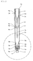
FIG. 1 is a view illustrating a feces sampling container according to one embodiment of the invention, wherein (a) is a plan view, (b) is a front view, and (c) is a bottom view. -
FIG. 2 is a cross-sectional view taken along the line A-A illustrated inFIG. 1 (see (b)). -
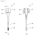
FIG. 3 is a view illustrating an example of a lid included in a feces sampling container according to one embodiment of the invention, wherein (a) is a plan view, and (b) is a cross-sectional view taken along the line B-B (see (a)). -
FIG. 4 is an enlarged view illustrating a part illustrated inFIG. 2 that is enclosed by a dash-dotted line. -
FIG. 5 is a cross-sectional view taken along the line D-D illustrated inFIG. 4 . -
FIG. 6 is a cross-sectional view (that corresponds toFIG. 5 ) illustrating a modification of a feces sampling container according to one embodiment of the invention. -
FIG. 7 is a cross-sectional view (that corresponds toFIG. 5 ) illustrating another modification of a feces sampling container according to one embodiment of the invention. -
FIG. 8 is a reference cross-sectional view illustrating an example of a screwed state of a dropping cap included in a feces sampling container according to one embodiment of the invention. -
FIG. 9 is a front view illustrating another example of a feces sampling container according to one embodiment of the invention. -
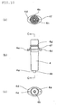
FIG. 10 is a view illustrating an example of an inside plug included in a feces sampling container according to one embodiment of the invention, wherein (a) is a plan view, (b) is a front view, and (c) is a bottom view. -
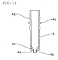
FIG. 11 is a cross-sectional view taken along the line C-C illustrated inFIG. 10 (see (b)). -
FIG. 12 is a view illustrating an example of a container body included in a feces sampling container according to one embodiment of the invention, wherein (a) is a plan view, (b) is a front view, and (c) is a bottom view. -
FIG. 13 is a view illustrating another example of an inside plug included in a feces sampling container according to one embodiment of the invention, wherein (a) is a side view, and (b) is a front view. -
FIG. 14 is a view illustrating a lid applied to another example of an inside plug included in a feces sampling container according to one embodiment of the invention, wherein (a) is a minor axis-side cross-sectional view illustrating the lid, and (b) is a major axis-side cross-sectional view illustrating the lid. - Preferred embodiments of the invention are described below with reference to the drawings.
- A
feces sampling container 1 according to one embodiment of the invention is used to sample feces that are subjected to fecal examination. As illustrated inFIGS. 1 and2 , thefeces sampling container 1 includes alid 2 that seals the inner space of thefeces sampling container 1, acontainer body 3 that has a tubular shape and holds a preservation solution, aninside plug 4 that is fitted to the inside of thecontainer body 3, and a droppingcap 5 that is screwed to the end of thecontainer body 3. - As illustrated in
FIG. 3 , thelid 2 of thefeces sampling container 1 includes acap 2a that seals the inner space of thefeces sampling container 1, and afeces sampling rod 2b for sampling feces. Ahelical groove 2c is helically formed on the end side of thefeces sampling rod 2b. When sampling the feces using thefeces sampling rod 2b, thelid 2 is removed from theinside plug 4 that is fitted to the inside of thecontainer body 3, and by, for example, thrusting thefeces sampling rod 2b into the feces, the feces is scraped off in thehelical groove 2c. After sampling the feces, thelid 2 is fitted to theinside plug 4 and thefeces sampling rod 2b is returned to the inside of thecontainer body 3 so that the sampled feces are suspended in the preservation solution held in thecontainer body 3. - In this embodiment, the
helical groove 2c is formed on the front end side of thefeces sampling rod 2b. The configuration is not limited thereto as long as the feces can be reliably sampled. For example, a plurality of grooves that encircle thefeces sampling rod 2b in the direction orthogonal to the longitudinal direction may be provided on the end side of thefeces sampling rod 2b. Alternatively, one or more recesses or through-holes having an arbitrary shape may be provided. Various feces sampling tools have been developed for sampling various types of feces (e.g., solid feces, soft feces, and liquid feces). - It is preferable that the
feces sampling rod 2b be colored with a color having high brightness (e.g. white or pale color) in order to improve the visibility of the feces that adhere to thefeces sampling rod 2b. It is more preferable that thefeces sampling rod 2b be colored pale green that is close to the color that is complementary to the color (brown to yellowish brown) of feces. - The
lid 2 of thefeces sampling container 1 is fitted through the engagement of acircular protrusion 4g that is formed on the outer circumferential surface of theinside plug 4 along the circumferential direction with acircular protrusion 2f that is formed on the inner circumferential surface of thecap 2a along the circumferential direction to seal the inner space of thefeces sampling container 1. Note that thelid 2 may be fitted using another means. For example, thelid 2 may be screwed to theinside plug 4 through the engagement of a thread formed on the inner circumferential surface of the cap with a thread formed on the outer circumferential surface of the inside plug 4 (not illustrated in the drawings) as long as it is possible to seal the inner space of thefeces sampling container 1. - It is also effective to form a circular protrusion that comes in contact with the edge of the
inside plug 4 on the inner surface of thecap 2a (not illustrated in the drawings) in order to improve the sealing capability when thelid 2 is fitted to the container. - The
feces sampling container 1 according to one embodiment of the invention is configured so that the inner space of thefeces sampling container 1 is sealed by causing thecap 2a to come in contact with the inner circumferential surface of theinside plug 4, while a gap is formed between the outer circumferential surface of theinside plug 4 and thecap 2a. For example, when the feces adhere to the edge of theinside plug 4 by mistake when returning thefeces sampling rod 2b to the container after sampling the feces, the feces enter the gap formed between the outer circumferential surface of theinside plug 4 and thecap 2a (i.e., the feces do not flow out from the feces sampling container 1). - It is preferable to produce the
lid 2 by integrally forming thecap 2a and thefeces sampling rod 2b by injection molding. Note that thecap 2a and thefeces sampling rod 2b may be formed separately. A specific configuration of thelid 2 is not particularly limited as long as thelid 2 can seal the inner space of thefeces sampling container 1 by thecap 2a, and thefeces sampling rod 2b has a hardness sufficient to thrust it into the feces. - The suspension in which the sampled feces are suspended in the preservation solution is discharged through an
outlet 3a that is formed on the end of thecontainer body 3 by squeezing thecontainer body 3, and dropped from the droppingcap 5 that is fitted to the end of thecontainer body 3. - Each member of the
feces sampling container 1 may be produced by injection molding or the like using a thermoplastic resin such as polypropylene or polyethylene. Thecontainer body 3 is produced using a polyolefin resin (e.g., linear low-density polyethylene, low-density polyethylene, or polypropylene) so that thecontainer body 3 can be squeezed. It is preferable to use linear low-density polyethylene from the viewpoint of squeeze capability, water transmission resistance, and injection moldability. - In one embodiment of the invention, the
container body 3 is preferably formed to have a cylindrical shape or a tubular shape having an elliptical or oval cross section, and athin part 3t in which the inner circumferential surface of the side wall is depressed is formed in the vicinity of the end of thecontainer body 3. This makes it possible to easily drop a predetermined amount of suspension by squeezing thecontainer body 3 without impairing the squeeze capability, the strength, and the water transmission resistance of thecontainer body 3. -
FIG. 4 is an enlarged view illustrating the part of thefeces sampling container 1 illustrated inFIG. 2 that is enclosed by the dash-dotted line. - An area of the
container body 3 in which thethin part 3t is formed is selected so that the worker can easily squeeze thecontainer body 3 with fingers, and thecontainer body 3 that has been squeezed and deformed does not interfere with other constituent members. More specifically, it is preferable to form thethin part 3t within a range R from a position that corresponds to the end of thefeces sampling rod 2b or the vicinity of the end of thefeces sampling rod 2b to a position situated close to astep 3g of thecontainer body 3 in a state in which the inner space of thefeces sampling container 1 is sealed with thelid 2, and the droppingcap 5 is fitted to thecontainer body 3. - Note that the position that corresponds to the end of the
feces sampling rod 2b or the vicinity of the end of thefeces sampling rod 2b refers to a position within a range r1 of about ±10 mm with respect to the end of thefeces sampling rod 2b along the longitudinal direction, and the position situated close to thestep 3g of thecontainer body 3 refers to a position situated at a distance r2 of about 1 mm or more from thestep 3g which formed on the end side of thecontainer body 3 along the longitudinal direction, although the range r1 and the distance r2 may vary depending on the shape and the size of thefeces sampling container 1. - Note that the
step 3g of thecontainer body 3 is formed as a result of forming a fitting part to which the droppingcap 5 is fitted on the end side of thecontainer body 3. - As illustrated in
FIG. 5 (that is a cross-sectional view taken along the line D-D illustrated inFIG. 4 ), thethin part 3t may be provided over the entire inner circumferential surface of the side wall of thecontainer body 3. Alternatively, a plurality of groove-likethin parts 3t may be formed in the inner circumferential surface of the side wall of thecontainer body 3 so as to extend in the longitudinal direction (seeFIG. 6 ). Alternatively, thethin part 3t may be formed by depressing the inner circumferential surface of the side wall of thecontainer body 3 so as to have an elliptical cross section (seeFIG. 7 ). - The ratio t/T of the thickness t of the
thin part 3t to the thickness T of the side wall is preferably 0.2 to 0.95. If the ratio t/T exceeds 0.95, the difference in thickness between thethin part 3t and the remaining part is small, and it may be difficult to obtain the advantageous effects of the invention. If the ratio t/T is less than 0.2, the fluidity of a molten resin when producing thecontainer body 3 by injection molding may be impaired, and thecontainer body 1 may exhibit insufficient strength. - In one embodiment of the invention, the
container body 3 includes apartition wall 3b which is situated on the end of thecontainer body 3 and in which theoutlet 3a is formed. The droppingcap 5 that is fitted to the end side of thecontainer body 3 by screwing (screw tightening) includes a sealingbody 5a that seals theoutlet 3a. Thefeces sampling container 1 according to one embodiment of the invention is thus configured so that theoutlet 3a is opened by loosening the dropping cap 5 (seeFIG. 2 ), and re-sealed by re-tightening the droppingcap 5. - Note that
FIG. 2 is a cross-sectional view taken along the line A-A illustrated inFIG. 1 in a state in which the droppingcap 5 has been loosened. - In one embodiment of the invention, a first
circular protrusion 3d is formed on the outer circumferential surface of the end side of the container body 3 (to which the droppingcap 5 is fitted) at a predetermined position along the circumferential direction. A secondcircular protrusion 5b is formed on the inner circumferential surface of the droppingcap 5 at a predetermined position along the circumferential direction. - The position at which the first
circular protrusion 3d is formed on the outer circumferential surface of the end side of thecontainer body 3, and the position at which the secondcircular protrusion 5b is formed on the inner circumferential surface of the droppingcap 5, are appropriately adjusted so that the firstcircular protrusion 3d and the secondcircular protrusion 5b come in contact with each other when the sealingbody 5a has moved away from theoutlet 3a and theoutlet 3a has been opened as a result of loosening the dropping cap 5 (seeFIG. 2 ). According to this configuration, it is possible to perceive that thefeces sampling container 1 has been opened by feeling that the firstcircular protrusion 3d and the secondcircular protrusion 5b have came in contact with each other, and prevent a situation in which the droppingcap 5 falls as a result of loosening the droppingcap 5 to a large extent. - In one embodiment of the invention, a body-
side thread 3e is formed on the outer circumferential surface of the end side of thecontainer body 3, and a cap-side thread 5c is formed on the inner circumferential surface of the droppingcap 5 so that the droppingcap 5 can be screwed to thecontainer body 3. It is preferable to form the body-side thread 3e of thecontainer body 3 and the cap-side thread 5c of the droppingcap 5 so that either or both of the body-side thread 3e and the cap-side thread 5c are decreased in height or removed within a range in which the body-side thread 3e and the cap-side thread 5c engage with each other in a state in which the firstcircular protrusion 3d and the secondcircular protrusion 5b come in contact with each other, such that the body-side thread 3e and the cap-side thread 5c can climb over each other. -
FIG. 8 illustrates an example of a configuration in which the body-side thread 3e of thecontainer body 3 and the cap-side thread 5c of the droppingcap 5 can climb over each other. -
FIG. 8(a) illustrates an example in which the cap-side thread 5c of the droppingcap 5 is decreased in height within a range fromthread 5c1 to 5c2 situated on the side of the secondcircular protrusion 5b.FIG. 8(b) illustrates an example in which the body-side thread 3e of thecontainer body 3 is removed within a range fromthread 3e1 to 3e2 (indicated by the dot-dash lines) situated away from the firstcircular protrusion 3d.FIG. 8(c) illustrates an example in which the body-side thread 3e of thecontainer body 3 is removed within a range ofthread 3e1 (indicated by the dot-dash lines), and the cap-side thread 5c of the droppingcap 5 is decreased in height within a range fromthread 5c1 to 5c2. - In such a case, when the
feces sampling container 1 has been opened, and the firstcircular protrusion 3d and the secondcircular protrusion 5b have come in contact with each other, the droppingcap 5 runs idle with respect to thecontainer body 3. Due to such idling of the droppingcap 5 with respect to thecontainer body 3, examination is performed without removing the droppingcap 5 from thecontainer body 3, and it is possible to prevent a situation in which the dropping cap required for re-sealing is lost. - In one embodiment of the invention, it is preferable to wind a tape-like member 7 (in which a
perforated line 7a is formed along the circumferential direction) (seeFIG. 9 ) around thefeces sampling container 1 so that theperforated line 7a is situated at the boundary between thecontainer body 3 and the droppingcap 5. This makes it possible to prevent a situation in which the droppingcap 5 loosens before thefeces sampling container 1 is opened (before examination), and easily determine whether or not thefeces sampling container 1 has been opened. - The base end side of the
container body 3 is open so that theinside plug 4 can be fitted to the inside of thecontainer body 3. The inner circumferential surface of thecontainer body 3 and the outer circumferential surface of theinside plug 4 liquid-tightly come in contact with each other when theinside plug 4 is fitted to the inside of thecontainer body 3 so that leakage of the preservation solution held in thecontainer body 3 does not occur. - As illustrated in
FIGS. 10 and11 , the end of theinside plug 4 that is fitted to the inside of thecontainer body 3 has abottom surface 4a that extends in the direction orthogonal to the longitudinal direction, and aremoval part 4b into which thefeces sampling rod 2 of thelid 2b can be inserted is formed at the center of thebottom surface 4a. Theremoval part 4b is designed to remove excess feces that adhere to thefeces sampling rod 2b when thefeces sampling rod 2b is returned to thecontainer body 3 after the feces have been sampled. In one embodiment of the invention, theremoval part 4b is formed in the shape of a tube that opens at the center of thebottom surface 4a. Theremoval part 4b is formed so that excess feces are removed when thefeces sampling rod 2b liquid-tightly comes in contact with the inner circumferential surface of theremoval part 4b, and slides on the inner circumferential surface of theremoval part 4b. This makes it possible to suspend a predetermined amount of feces with which thehelical groove 2c is filled in the preservation solution held in thecontainer body 3. - The
inside plug 4 constituting theremoval part 4b may have a tapered outer shape in which the diameter of theinside plug 4 gradually decreases toward theremoval part 4b from the middle of theinside plug 4 so that thefeces sampling rod 2b can be reliably guided to theremoval part 4b. - In this case, however, a gap is formed between the side of the tapered part and the inner surface of the
container body 3, whereby the volume of the preservation solution-holding part increases. If the volume of the preservation solution-holding part is too large, the end of thefeces sampling rod 2b may be exposed to air when thefeces sampling container 1 is stored horizontally (or stored in a state in which the droppingcap 5 is situated on the upper side) after the feces have been sampled, whereby the stability of the measurement target components included in the feces may be impaired. Therefore, it is preferable to form theinside plug 4 to have a shape that reduces the volume of the preservation solution-holding part as much as possible. - Accordingly, it is preferable to form the
inside plug 4 to have an approximately cylindrical outer shape, and form thebottom surface 4a to have a flat shape that is orthogonal to the longitudinal direction, or to have a shape that is depressed from the periphery toward theremoval part 4b that is situated at the center. - In one embodiment of the invention, a feces sampling rod guide that includes a plurality of tilted
ribs 4c that are provided radially is formed around theremoval part 4b so that thefeces sampling rod 2b can be easily inserted into theremoval part 4b when thefeces sampling rod 2b is returned to the inside of thecontainer body 3 after the feces have been sampled. - In one embodiment of the invention, the tilted
ribs 4c are formed so as to form a triangular shape that has a side that extends diagonally from the edge of theremoval part 4b. Note that the shape of the tiltedribs 4c is not particularly limited as long as thefeces sampling rod 2b can be guided to theremoval part 4b. - The
feces sampling rod 2b can be guided to theremoval part 4b by forming a cone-shaped part around theremoval part 4b. In this case, however, since the thickness of the side of thebottom surface 4a of the end of theinside plug 4 increases, the amount of resin required to form theinside plug 4 increases, and it takes time to cool the product (i.e., the production speed decreases). Moreover, the amount of shrinkage of the resin during cooling increases, and deterioration in dimensional stability occurs. The feces sampling rod guide can be formed by disposing a plurality of tiltedribs 4c radially and providing a space between adjacent the tiltedribs 4c, thereby such disadvantages can be effectively eliminated. - The
feces sampling container 1 according to one embodiment of the invention is opened by loosening the droppingcap 5 after suspending the feces sampled using thefeces sampling rod 2b in the preservation solution held in thecontainer body 3. The suspension obtained by suspending the feces in the preservation solution is discharged through theoutlet 3a provided on the end of thecontainer body 3 by squeezing thecontainer body 3, and filtered through afilter 6 that is provided to the droppingcap 5, and the filtrate is dropped and subjected to examination. - A material for forming the
filter 6 that is provided to the droppingcap 5 is not particularly limited as long as thefilter 6 can remove a solid that hinders the examination from the suspension, and is inert to the examination target. Examples of the material for forming thefilter 6 include a porous substance (e.g., Moltofilter, paper filter, and sintered resin filter), a fibrous substance (e.g., glass wool and absorbent cotton), and the like. It is preferable to use a Moltofilter or a sintered resin filter having a predetermined pore size. Thefilter 6 may include only one type of filter, or may be formed by stacking two or more types of filters. - An arbitrary preservation solution that is suitable for fecal examination may be used as the preservation solution in which the sampled feces are suspended. An additive such as a buffer, a stabilizer, a preservative, a dye, or an odor absorber may optionally be added to the preservation solution. The amount of the preservation solution held in the container body is appropriately adjusted corresponding to the feces suspension concentration required for fecal examination. For example, when sampling 5 mg of feces, a dilution ratio of 400 is obtained by adjusting the amount of the preservation solution to 2 ml.
- In one embodiment of the invention, a
flange 3c is formed along the edge of the base end-side opening of the container body 3 (seeFIG. 12 ). Anoverhang 4d is formed on the outer circumferential surface of the inside plug 4 (seeFIG. 10 ) along the circumferential direction at a position at which theoverhang 4d is situated on theflange 3c of thecontainer body 3 when theinside plug 4 is fitted to the inside of thecontainer body 3. - In one embodiment of the invention, since the
removal part 4b with which thefeces sampling rod 2b liquid-tightly comes in contact and which removes excess feces is formed on the end of theinside plug 4, it is preferable to form theinside plug 4 using a hard material. Thecontainer body 3 may be formed using a soft material taking account of the squeeze capability. In this case, thecontainer body 3 and theinside plug 4 are formed using different types of materials that are difficult to weld. Therefore, when securing theinside plug 4 that is fitted to the inside of thecontainer body 3, it is desirable to prevent a situation in which theinside plug 4 rotates with respect to thecontainer body 3, or theinside plug 4 rotates together with thelid 2 when fitting or removing thelid 2 to or from theinside plug 4. In one embodiment of the invention, an engagement part that is formed by anotch 3f is provided to theflange 3c formed on thecontainer body 3, and a locking part that is formed by aprotrusion 4e that engages with thenotch 3f is provided to theoverhang 4d formed on the inside plug 4 (see the drawings) to prevent a situation in which theinside plug 4 rotates with respect to thecontainer body 3, or theinside plug 4 rotates together with thelid 2 when fitting or removing the lid 2 (having thefeces sampling rod 2b) to or from theinside plug 4. - Note that the engagement part that is provided to the
flange 3c formed on thecontainer body 3 may be formed by a groove, a through-hole, or the like instead of thenotch 3f, and the shape of the locking part provided to theoverhang 4d formed on theinside plug 4 may be appropriately selected corresponding to the shape of the engagement part. The engagement part may be provided to theoverhang 4d formed on theinside plug 4, and the locking part may be provided to theflange 3c formed on thecontainer body 3. - It is preferable to form the
flange 3c that is formed on thecontainer body 3 and theoverhang 4d that is formed on theinside plug 4 to have a diamond shape (see the drawings), an elliptical shape, a track shape, or the like (i.e., a shape that is longer in one of two orthogonal directions) in order to prevent the rolling of thefeces sampling container 1 during examination. - As illustrated in
FIG. 3 ,blades 2d that make a pair and make it possible to easily turn thelid 2 are symmetrically formed on thecap 2a of thelid 2, and the side of the lower end of thecap 2a of thelid 2 situated at the lower end side of eachblade 2d is partially swelled (expanded) to form a hollow to symmetrically formsloping grooves 2e that make a pair and slope outward in the downward direction (on the upper end). As illustrated inFIG. 10 , slopingprotrusions 4f that make a pair and slope outward in the downward direction (at least on the upper end side) are symmetrically formed on the major axis-side inner circumferential surface of theoverhang 4d of theinside plug 4. According to this configuration, it is possible to turn thelid 2 while holding theblades 2d of thelid 2 with fingers to easily remove thelid 2 from theinside plug 4 by utilizing a removal mechanism that is formed by the slopinggroove 2e of thelid 2 and thesloping protrusion 4f of theinside plug 4. - Note that it is preferable that the upper part of each side of the
sloping groove 2e of thelid 2 and the upper part of each side of thesloping protrusion 4f of theinside plug 4 that form the removal mechanism have an identical shape (preferably a linear shape or a curved shape (concave shape)) so that thelid 2 can be turned smoothly in an arbitrary direction. - Although an example in which the
sloping grooves 2e that make a pair are symmetrically provided to thelid 2, and the slopingprotrusions 4f that make a pair are symmetrically provided to theinside plug 4 has been described above, only one slopinggroove 2e may be provided to thelid 2, or only one slopingprotrusion 4f may be provided to theinside plug 4. The slopinggroove 2e that is formed in thelid 2 may be provided to the side of the lower end of thecap 2a that is orthogonal to theblade 2d, and thesloping protrusion 4f that is formed on theinside plug 4 may be provided to the minor axis-side inner circumferential surface of theoverhang 4d. Note that it is preferable to form thesloping groove 2e at the lower end side of theblade 2d of thecap 2a of thelid 2, and form thesloping protrusion 4f on the major axis-side inner circumferential surface of theoverhang 4d of theinside plug 4 since it is easy to form thesloping groove 2e and thesloping protrusion 4f. - In this case, when fitting the
lid 2 to theinside plug 4, the slopinggroove 2e of thelid 2 and thesloping protrusion 4f of theinside plug 4 that form the removal mechanism are positioned, and thecircular protrusion 2f formed on the inner circumferential surface of thecap 2a of thelid 2 and thecircular protrusion 4g formed on the outer circumferential surface of theinside plug 4 engage with each other. As illustrated inFIG. 13 ,guide cams 4h that make a pair and slope downward with respect to the axial direction from the apex side to form an inverted V-like shape (so that the lower end preferably extends parallel to the axial direction) are symmetrically formed over thecircular protrusion 4g of theinside plug 4. As illustrated inFIG. 14 , elongatedprotrusions 2h that make a pair and extend along the axial direction are symmetrically formed over thecircular protrusion 2f of thecap 2a of thelid 2. Theguide cam 4h of theinside plug 4 and theelongated protrusion 2h of thelid 2 form a cam mechanism, and theelongated protrusion 2h of thelid 2 is guided by theguide cam 4h of theinside plug 4 when pushing thelid 2 having thefeces sampling rod 2b into theinside plug 4 while turning thelid 2. This makes it possible to easily and reliably fit thelid 2 to theinside plug 4 in a state in which thesloping groove 2e of thelid 2 and thesloping protrusion 4f of theinside plug 4 that form the removal mechanism engage with each other. - When the
flange 3c that is formed on thecontainer body 3 and theoverhang 4d that is formed on theinside plug 4 have a shape that is longer in one of two orthogonal directions, and theblade 2d is formed on thecap 2a of thelid 2, it is preferable to form theguide cam 4h of theinside plug 4 that forms the cam mechanism on the minor axis side of theoverhang 4d of theinside plug 4, and form theelongated protrusion 2h of thelid 2 at the same position as theblade 2d and thesloping groove 2e of thecap 2a. According to this configuration, it is possible to prevent a situation in which thecap 2a of thelid 2 sinks during molding, and ensure that theblade 2d formed on thecap 2a is positioned on the major axis side of theflange 3c formed on thecontainer body 3 and theoverhang 4d formed on theinside plug 4. - Although an example in which the elongated
protrusions 2h are symmetrically provided to thelid 2, and theguide cams 4h are symmetrically provided to theinside plug 4 has been described above, only oneelongated protrusion 2h may be provided to thelid 2, or only oneguide cam 4h may be provided to theinside plug 4. Note that it is preferable to symmetrically form a pair ofelongated protrusions 2h and a pair ofguide cams 4h from the viewpoint of the engagement of thelid 2 with theinside plug 4, and ease and stability of immobilization. Theguide cam 4h of theinside plug 4 may be formed on the major axis side of theoverhang 4d, and theelongated protrusion 2h of thelid 2 may be formed to be orthogonal to theblade 2d and thesloping groove 2e. - The preferred embodiments of the invention have been described above. Note that the invention is not limited to the above embodiments, and various modifications and variations may be made without departing from the scope of the invention.
- Although the above embodiments have been described taking an example in which the
removal part 4b is provided inside thecontainer body 3 by fitting theinside plug 4 provided with theremoval part 4b to the inside of thecontainer body 3, theinside plug 4 may be omitted, and theremoval part 4b may be formed directly inside thecontainer body 3. - As described above, the invention can be applied to a feces sampling container that is used to sample feces that are subjected to fecal examination.
-
- 1
- Feces sampling container
- 2
- Lid
- 2a
- Cap
- 2b
- Feces sampling rod
- 2d
- Blade
- 2e
- Sloping groove
- 2f
- Circular protrusion
- 2h
- Elongated protrusion
- 3
- Container body
- 3a
- Outlet
- 3c
- Flange
- 3d
- First circular protrusion
- 3e
- Body-side thread
- 3f
- Notch
- 3g
- Step
- 3t
- Thin part
- 4
- Inside plug
- 4a
- Bottom surface
- 4b
- Removal part
- 4c
- Tilted rib
- 4d
- Overhang
- 4e
- Protrusion
- 4f
- Sloping protrusion
- 4g
- Circular protrusion
- 4h
- Guide cam
- 5
- Dropping cap
- 5a
- Sealing body
- 5b
- Second circular protrusion
- 5c
- Cap-side thread
- 7
- Tape-like member
- 7a
- Perforated line
Claims (18)
- A feces sampling container comprising:a lid that comprises a feces sampling rod and a cap, a circular protrusion being formed on an inner circumferential surface of the cap along a circumferential direction;a container body that has a tubular shape and opens on a base end side; andan inside plug that comprises a removal part and a circular protrusion, the circular protrusion being formed on an outer circumferential surface of the inside plug along a circumferential direction, the inside plug being fitted to inside of the container body through the base end side of the container body,a flange being formed along an edge of a base end side opening of the container body,an overhang being formed on an outer circumferential surface of the inside plug at a given position along a circumferential direction so that the overhang is situated on the flange,a removal mechanism being formed at a lower end of the cap and on an inner circumferential surface of the overhang of the inside plug, anda cam mechanism that positions the removal mechanism being formed over the circular protrusions formed on the inner circumferential surface of the cap and the circular protrusion formed on the outer circumferential surface of the inside plug.
- The feces sampling container according to claim 1, wherein the flange and the overhang are formed to have a shape that is longer in one of two orthogonal directions.
- The feces sampling container according to claim 1 or 2, wherein blades that make a pair are symmetrically formed on the cap of the lid.
- The feces sampling container according to any one of claims 1 to 3, wherein the removal mechanism comprises a sloping groove that is formed by partially swelling a side of the lower end of the cap to form a hollow, and slopes outward in a downward direction on an upper end side, and a sloping protrusion that is formed on the inner circumferential surface of the overhang, and slopes outward in a downward direction at least on an upper end side.
- The feces sampling container according to claim 4, wherein the sloping groove is formed at a lower end side of the blade of the cap, and the sloping protrusion is formed on a major axis-side inner circumferential surface of the overhang of the inside plug.
- The feces sampling container according to any one of claims 1 to 5, wherein the cam mechanism comprises a guide cam that is formed over the circular protrusion formed on the outer circumferential surface of the inside plug, and slopes downward with respect to an axial direction from the apex side to form an inverted V-like shape, and an elongated protrusion that is formed over the circular protrusion formed on the inner circumferential surface of the cap of the lid, and extends along an axial direction.
- The feces sampling container according to claim 6, wherein the guide cam is formed on a minor axis side of the overhang of the inside plug, and the elongated protrusion is formed at the same position as the blade and the sloping groove of the cap.
- The feces sampling container according to any one of claims 1 to 7, wherein the removal mechanisms that make a pair and the cam mechanisms that make a pair are respectively formed symmetrically.
- The feces sampling container according to any one of claims 1 to 8, wherein an engagement part is provided to one of the flange and the overhang, and a locking part that is fitted to the engagement part is provided to the other of the flange and the overhang.
- The feces sampling container according to claim 9, wherein the engagement part is a notch, and the locking part is a protrusion.
- The feces sampling container according to any one of claims 1 to 10, wherein an end of the inside plug has a bottom surface that extends in a direction orthogonal to a longitudinal direction, a removal part is formed at a center of the bottom surface, and a feces sampling rod guide that comprises a plurality of tilted ribs that are provided radially is formed around the removal part.
- The feces sampling container according to any one of claims 1 to 11, wherein an outlet is formed on an end side of the container body, and a dropping cap that comprises a sealing body that seals the outlet is screwed to the container body.
- The feces sampling container according to claim 12, wherein a first circular protrusion is formed on an outer circumferential surface of an end side of the container body at a predetermined position along a circumferential direction, a second circular protrusion is formed on an inner circumferential surface of the dropping cap at a predetermined position along a circumferential direction, and the first circular protrusion and the second the circular protrusion come in contact with each other to prevent the dropping cap from falling when the dropping cap is loosened so that the sealing body moves away from the outlet and the outlet is opened.
- The feces sampling container according to claim 13, wherein a body-side thread is formed on the outer circumferential surface of the end side of the container body to which the dropping cap is screwed, and a cap-side thread is formed on the inner circumferential surface of the dropping cap so that either or both of the body-side thread and the cap-side thread are decreased in height or removed within a range in which the body-side thread and the cap-side thread engage with each other in a state in which the first circular protrusion and the second circular protrusion come in contact with each other, such that the body-side thread and the cap-side thread can climb get over each other.
- The feces sampling container according to any one of claims 12 to 14, wherein a tape-like member in which a perforated line is formed along a circumferential direction is wound around the feces sampling container so that the perforated line is situated at a boundary between the container body and the dropping cap.
- The feces sampling container according to any one of claims 1 to 15, wherein a thin part in which an inner circumferential surface of a side wall is depressed is formed in a vicinity of an end of the container body.
- The feces sampling container according to any one of claims 1 to 16, wherein the thin part is formed within a range from a position that corresponds to an end of the feces sampling rod or a vicinity of the end of the feces sampling rod to a position situated close to a step of the container body in a state in which an inner space of the feces sampling container is sealed with the lid, and the dropping cap is fitted to the container body.
- The feces sampling container according to claim 16 or 17, wherein the container body is formed using linear low-density polyethylene, low-density polyethylene, or polypropylene.
Applications Claiming Priority (3)
| Application Number | Priority Date | Filing Date | Title |
|---|---|---|---|
| JP2013212995A JP6216602B2 (en) | 2013-10-10 | 2013-10-10 | Stool collection container |
| JP2014000610U JP3190154U (en) | 2014-02-07 | 2014-02-07 | Stool collection container |
| PCT/JP2014/005035 WO2015052901A1 (en) | 2013-10-10 | 2014-10-02 | Feces sampling container |
Publications (3)
| Publication Number | Publication Date |
|---|---|
| EP3056890A1 true EP3056890A1 (en) | 2016-08-17 |
| EP3056890A4 EP3056890A4 (en) | 2017-05-24 |
| EP3056890B1 EP3056890B1 (en) | 2020-04-29 |
Family
ID=53502341
Family Applications (1)
| Application Number | Title | Priority Date | Filing Date |
|---|---|---|---|
| EP14853123.9A Active EP3056890B1 (en) | 2013-10-10 | 2014-10-02 | Feces sampling container |
Country Status (7)
| Country | Link |
|---|---|
| US (1) | US9867598B2 (en) |
| EP (1) | EP3056890B1 (en) |
| KR (1) | KR102289358B1 (en) |
| CN (1) | CN105518434B (en) |
| CA (1) | CA2924297C (en) |
| MX (1) | MX370208B (en) |
| WO (1) | WO2015052901A1 (en) |
Families Citing this family (10)
| Publication number | Priority date | Publication date | Assignee | Title |
|---|---|---|---|---|
| CN104849440B (en) | 2015-05-28 | 2017-07-11 | 万华普曼生物工程有限公司 | Acquisition testing integrated device with anti-error assembling structure |
| US10859583B2 (en) | 2015-12-16 | 2020-12-08 | Hitachi Chemical Diagnostics Systems Co., Ltd. | Feces sampling container, method for measuring components in feces sample, method for stabilizing components in feces sample, and method for storing feces sample |
| US11375986B1 (en) * | 2018-07-27 | 2022-07-05 | The University Of Chicago | Device and method for stool sample collection |
| CN108801672B (en) * | 2018-09-04 | 2024-06-28 | 深圳市鸿美诊断技术有限公司 | Quantitative fecal sampler |
| EP3880083A1 (en) * | 2018-11-13 | 2021-09-22 | ProciseDx Inc. | Fecal sampler |
| JP7151491B2 (en) * | 2019-01-08 | 2022-10-12 | Dicプラスチック株式会社 | test container |
| US11458476B2 (en) * | 2019-10-17 | 2022-10-04 | Marvin Liu | In-situ fecal specimen sampling device |
| CN113116398B (en) * | 2019-12-31 | 2025-08-15 | 苏州图灵微生物科技有限公司 | Sampling device |
| KR102623033B1 (en) * | 2021-08-02 | 2024-01-10 | 손동우 | Dispensor apparatus for sample collection and storage |
| CN117516994B (en) * | 2023-12-04 | 2024-04-26 | 河北省畜牧总站(河北省奶源工作总站) | Livestock and poultry manure sampling equipment and method |
Family Cites Families (33)
| Publication number | Priority date | Publication date | Assignee | Title |
|---|---|---|---|---|
| DE10205709A1 (en) * | 2002-02-12 | 2003-08-28 | Schebo Biotech Ag | Sample preparation device and test device set based thereon |
| JP2914761B2 (en) | 1990-12-07 | 1999-07-05 | ソーダニッカ株式会社 | Biological sampling container for testing |
| JPH0726701Y2 (en) | 1991-03-08 | 1995-06-14 | 東洋製罐株式会社 | Sample collection container |
| JPH06317583A (en) * | 1991-08-15 | 1994-11-15 | Nissho Corp | Stool sampling container |
| US5451525A (en) * | 1992-02-14 | 1995-09-19 | Coulter Corporation | Method and materials for determining particle count in a flow cytometer |
| JP3242498B2 (en) | 1992-09-16 | 2001-12-25 | 富士レビオ株式会社 | Feces collection tool |
| JP2665867B2 (en) | 1992-12-18 | 1997-10-22 | 栄研化学株式会社 | Transport collection container |
| JP2717621B2 (en) | 1993-08-30 | 1998-02-18 | 栄研化学株式会社 | Transport collection container |
| TW235237B (en) | 1992-12-18 | 1994-12-01 | Eiken Chemical | |
| JP2668815B2 (en) * | 1993-06-22 | 1997-10-27 | 東洋製罐株式会社 | Transport collection container |
| JPH08189928A (en) | 1995-01-10 | 1996-07-23 | Dainippon Printing Co Ltd | Fecal occult blood detector |
| US5882942A (en) | 1995-02-15 | 1999-03-16 | Wako Pure Chemical Industries, Ltd. | Method for sampling feces |
| JP3613876B2 (en) * | 1995-02-15 | 2005-01-26 | 和光純薬工業株式会社 | Fecal collection tool |
| JPH08292189A (en) * | 1995-04-21 | 1996-11-05 | Nissho Corp | Stool collection container |
| JP3424403B2 (en) | 1995-08-18 | 2003-07-07 | 東洋製罐株式会社 | Sample collection container |
| JPH10243940A (en) * | 1997-03-03 | 1998-09-14 | I R Medical:Kk | Blood collection tube |
| JP3790009B2 (en) | 1997-04-21 | 2006-06-28 | ディックプラスチック株式会社 | Stool collection container |
| JP3622827B2 (en) * | 1998-05-06 | 2005-02-23 | ニプロ株式会社 | Stool collection container |
| JP2002131195A (en) | 2000-10-20 | 2002-05-09 | Sekisui Chem Co Ltd | Mail transport container |
| JP3867077B2 (en) * | 2003-03-28 | 2007-01-10 | 三光純薬株式会社 | Stool collection container |
| JP4319590B2 (en) * | 2004-07-12 | 2009-08-26 | アルフレッサファーマ株式会社 | Stool collection container |
| JP4662891B2 (en) | 2005-06-27 | 2011-03-30 | わかもと製薬株式会社 | Stool collection container |
| JP4696772B2 (en) | 2005-08-10 | 2011-06-08 | ニプロ株式会社 | Stool collection container |
| EP1986006A4 (en) * | 2005-12-16 | 2009-11-18 | Nipro Corp | Feces collection container |
| JP2007170979A (en) | 2005-12-22 | 2007-07-05 | Dic Plastics Inc | Feces sampling container |
| JP5021323B2 (en) | 2007-01-25 | 2012-09-05 | 東洋製罐株式会社 | Inspection container |
| CN102015482B (en) | 2008-04-24 | 2013-07-17 | 东洋制罐株式会社 | Compound container and pouring-out method |
| TW200946072A (en) * | 2008-05-09 | 2009-11-16 | Dic Plastics Inc | Device for sampling feces |
| JP4215117B1 (en) * | 2008-05-09 | 2009-01-28 | Dicプラスチック株式会社 | Stool collection container |
| DE102008057866B4 (en) * | 2008-11-18 | 2012-06-28 | Gaudlitz Gmbh | Chair sampling device |
| CN102246019B (en) * | 2008-12-12 | 2014-12-31 | 协和梅迪克斯株式会社 | toilet |
| JP5379061B2 (en) | 2010-03-31 | 2013-12-25 | 富士フイルム株式会社 | Extraction method and extraction container and extraction kit used therefor |
| CA2845572C (en) * | 2011-08-16 | 2019-10-29 | Exact Sciences Corporation | Sample collection device |
-
2014
- 2014-10-02 EP EP14853123.9A patent/EP3056890B1/en active Active
- 2014-10-02 US US15/026,999 patent/US9867598B2/en active Active
- 2014-10-02 CA CA2924297A patent/CA2924297C/en not_active Expired - Fee Related
- 2014-10-02 MX MX2016004566A patent/MX370208B/en active IP Right Grant
- 2014-10-02 CN CN201480048223.3A patent/CN105518434B/en not_active Expired - Fee Related
- 2014-10-02 WO PCT/JP2014/005035 patent/WO2015052901A1/en not_active Ceased
- 2014-10-02 KR KR1020167004205A patent/KR102289358B1/en active Active
Also Published As
| Publication number | Publication date |
|---|---|
| KR102289358B1 (en) | 2021-08-11 |
| US20160256136A1 (en) | 2016-09-08 |
| MX2016004566A (en) | 2016-11-14 |
| WO2015052901A1 (en) | 2015-04-16 |
| US9867598B2 (en) | 2018-01-16 |
| MX370208B (en) | 2019-12-05 |
| CA2924297A1 (en) | 2015-04-16 |
| KR20160070054A (en) | 2016-06-17 |
| CN105518434B (en) | 2019-01-01 |
| CN105518434A (en) | 2016-04-20 |
| EP3056890B1 (en) | 2020-04-29 |
| CA2924297C (en) | 2021-10-26 |
| EP3056890A4 (en) | 2017-05-24 |
Similar Documents
| Publication | Publication Date | Title |
|---|---|---|
| EP3056890B1 (en) | Feces sampling container | |
| DE69413157T2 (en) | Collection tube | |
| JP6216602B2 (en) | Stool collection container | |
| EP3359460B1 (en) | Container for receiving an enteral nutrient solution | |
| US4057175A (en) | Serving container for liquids or pourable materials contained in cardboard packages | |
| EP3040703B1 (en) | Stool collection container | |
| JP6339788B2 (en) | Stool collection container | |
| JP3190154U (en) | Stool collection container | |
| JP6286175B2 (en) | Stool collection container | |
| JP2018076091A (en) | Sealing mouth plug | |
| JP2012012070A (en) | Spout cap for container | |
| CH711807A1 (en) | Container with a protruding into the container interior on the container recess for receiving a functional element. | |
| JP2007170979A (en) | Feces sampling container | |
| JP2009029478A (en) | Dispensing cap of container | |
| JP4840568B2 (en) | cap | |
| US20060016837A1 (en) | Twist-off container plug | |
| JP2009051553A (en) | Hinged cap | |
| JP2026064493A (en) | Sample collection container | |
| JP2009057098A (en) | Two-agent mixing vessel | |
| KR20110008833U (en) | Tube containers | |
| JP6249662B2 (en) | Hinge cap | |
| BE1014096A3 (en) | Test tube closure device with cap and stopper, has upper half of its exposed portion lying completely inside or outside stopper periphery | |
| JP2020033092A (en) | container | |
| JP2503455Y2 (en) | Container cap structure | |
| CA1206925A (en) | Container with reciprocable dispensing tube |
Legal Events
| Date | Code | Title | Description |
|---|---|---|---|
| PUAI | Public reference made under article 153(3) epc to a published international application that has entered the european phase |
Free format text: ORIGINAL CODE: 0009012 |
|
| 17P | Request for examination filed |
Effective date: 20160404 |
|
| AK | Designated contracting states |
Kind code of ref document: A1 Designated state(s): AL AT BE BG CH CY CZ DE DK EE ES FI FR GB GR HR HU IE IS IT LI LT LU LV MC MK MT NL NO PL PT RO RS SE SI SK SM TR |
|
| AX | Request for extension of the european patent |
Extension state: BA ME |
|
| RIN1 | Information on inventor provided before grant (corrected) |
Inventor name: SAITO, SHINGO Inventor name: HAYASHI, HIROAKI Inventor name: TOYAMA, KAZUHIRO Inventor name: ICHIKAWA, YOSHIHARU Inventor name: ISHIKAWA, MASASHI |
|
| RIN1 | Information on inventor provided before grant (corrected) |
Inventor name: ICHIKAWA, YOSHIHARU Inventor name: HAYASHI, HIROAKI Inventor name: TOYAMA, KAZUHIRO Inventor name: SAITO, SHINGO Inventor name: ISHIKAWA, MASASHI |
|
| DAX | Request for extension of the european patent (deleted) | ||
| A4 | Supplementary search report drawn up and despatched |
Effective date: 20170425 |
|
| RIC1 | Information provided on ipc code assigned before grant |
Ipc: B01L 3/00 20060101ALI20170418BHEP Ipc: G01N 33/48 20060101ALI20170418BHEP Ipc: G01N 1/04 20060101AFI20170418BHEP Ipc: A61B 10/00 20060101ALI20170418BHEP |
|
| STAA | Information on the status of an ep patent application or granted ep patent |
Free format text: STATUS: EXAMINATION IS IN PROGRESS |
|
| 17Q | First examination report despatched |
Effective date: 20180420 |
|
| GRAP | Despatch of communication of intention to grant a patent |
Free format text: ORIGINAL CODE: EPIDOSNIGR1 |
|
| STAA | Information on the status of an ep patent application or granted ep patent |
Free format text: STATUS: GRANT OF PATENT IS INTENDED |
|
| INTG | Intention to grant announced |
Effective date: 20191206 |
|
| GRAS | Grant fee paid |
Free format text: ORIGINAL CODE: EPIDOSNIGR3 |
|
| GRAA | (expected) grant |
Free format text: ORIGINAL CODE: 0009210 |
|
| STAA | Information on the status of an ep patent application or granted ep patent |
Free format text: STATUS: THE PATENT HAS BEEN GRANTED |
|
| AK | Designated contracting states |
Kind code of ref document: B1 Designated state(s): AL AT BE BG CH CY CZ DE DK EE ES FI FR GB GR HR HU IE IS IT LI LT LU LV MC MK MT NL NO PL PT RO RS SE SI SK SM TR |
|
| REG | Reference to a national code |
Ref country code: GB Ref legal event code: FG4D |
|
| REG | Reference to a national code |
Ref country code: CH Ref legal event code: EP |
|
| REG | Reference to a national code |
Ref country code: AT Ref legal event code: REF Ref document number: 1264051 Country of ref document: AT Kind code of ref document: T Effective date: 20200515 |
|
| REG | Reference to a national code |
Ref country code: DE Ref legal event code: R096 Ref document number: 602014064675 Country of ref document: DE |
|
| REG | Reference to a national code |
Ref country code: IE Ref legal event code: FG4D |
|
| REG | Reference to a national code |
Ref country code: NL Ref legal event code: MP Effective date: 20200429 |
|
| REG | Reference to a national code |
Ref country code: LT Ref legal event code: MG4D |
|
| PG25 | Lapsed in a contracting state [announced via postgrant information from national office to epo] |
Ref country code: IS Free format text: LAPSE BECAUSE OF FAILURE TO SUBMIT A TRANSLATION OF THE DESCRIPTION OR TO PAY THE FEE WITHIN THE PRESCRIBED TIME-LIMIT Effective date: 20200829 Ref country code: PT Free format text: LAPSE BECAUSE OF FAILURE TO SUBMIT A TRANSLATION OF THE DESCRIPTION OR TO PAY THE FEE WITHIN THE PRESCRIBED TIME-LIMIT Effective date: 20200831 Ref country code: NO Free format text: LAPSE BECAUSE OF FAILURE TO SUBMIT A TRANSLATION OF THE DESCRIPTION OR TO PAY THE FEE WITHIN THE PRESCRIBED TIME-LIMIT Effective date: 20200729 Ref country code: LT Free format text: LAPSE BECAUSE OF FAILURE TO SUBMIT A TRANSLATION OF THE DESCRIPTION OR TO PAY THE FEE WITHIN THE PRESCRIBED TIME-LIMIT Effective date: 20200429 Ref country code: SE Free format text: LAPSE BECAUSE OF FAILURE TO SUBMIT A TRANSLATION OF THE DESCRIPTION OR TO PAY THE FEE WITHIN THE PRESCRIBED TIME-LIMIT Effective date: 20200429 Ref country code: GR Free format text: LAPSE BECAUSE OF FAILURE TO SUBMIT A TRANSLATION OF THE DESCRIPTION OR TO PAY THE FEE WITHIN THE PRESCRIBED TIME-LIMIT Effective date: 20200730 Ref country code: FI Free format text: LAPSE BECAUSE OF FAILURE TO SUBMIT A TRANSLATION OF THE DESCRIPTION OR TO PAY THE FEE WITHIN THE PRESCRIBED TIME-LIMIT Effective date: 20200429 |
|
| REG | Reference to a national code |
Ref country code: AT Ref legal event code: MK05 Ref document number: 1264051 Country of ref document: AT Kind code of ref document: T Effective date: 20200429 |
|
| PG25 | Lapsed in a contracting state [announced via postgrant information from national office to epo] |
Ref country code: HR Free format text: LAPSE BECAUSE OF FAILURE TO SUBMIT A TRANSLATION OF THE DESCRIPTION OR TO PAY THE FEE WITHIN THE PRESCRIBED TIME-LIMIT Effective date: 20200429 Ref country code: LV Free format text: LAPSE BECAUSE OF FAILURE TO SUBMIT A TRANSLATION OF THE DESCRIPTION OR TO PAY THE FEE WITHIN THE PRESCRIBED TIME-LIMIT Effective date: 20200429 Ref country code: RS Free format text: LAPSE BECAUSE OF FAILURE TO SUBMIT A TRANSLATION OF THE DESCRIPTION OR TO PAY THE FEE WITHIN THE PRESCRIBED TIME-LIMIT Effective date: 20200429 Ref country code: BG Free format text: LAPSE BECAUSE OF FAILURE TO SUBMIT A TRANSLATION OF THE DESCRIPTION OR TO PAY THE FEE WITHIN THE PRESCRIBED TIME-LIMIT Effective date: 20200729 |
|
| PG25 | Lapsed in a contracting state [announced via postgrant information from national office to epo] |
Ref country code: AL Free format text: LAPSE BECAUSE OF FAILURE TO SUBMIT A TRANSLATION OF THE DESCRIPTION OR TO PAY THE FEE WITHIN THE PRESCRIBED TIME-LIMIT Effective date: 20200429 Ref country code: NL Free format text: LAPSE BECAUSE OF FAILURE TO SUBMIT A TRANSLATION OF THE DESCRIPTION OR TO PAY THE FEE WITHIN THE PRESCRIBED TIME-LIMIT Effective date: 20200429 |
|
| PG25 | Lapsed in a contracting state [announced via postgrant information from national office to epo] |
Ref country code: AT Free format text: LAPSE BECAUSE OF FAILURE TO SUBMIT A TRANSLATION OF THE DESCRIPTION OR TO PAY THE FEE WITHIN THE PRESCRIBED TIME-LIMIT Effective date: 20200429 Ref country code: ES Free format text: LAPSE BECAUSE OF FAILURE TO SUBMIT A TRANSLATION OF THE DESCRIPTION OR TO PAY THE FEE WITHIN THE PRESCRIBED TIME-LIMIT Effective date: 20200429 Ref country code: CZ Free format text: LAPSE BECAUSE OF FAILURE TO SUBMIT A TRANSLATION OF THE DESCRIPTION OR TO PAY THE FEE WITHIN THE PRESCRIBED TIME-LIMIT Effective date: 20200429 Ref country code: RO Free format text: LAPSE BECAUSE OF FAILURE TO SUBMIT A TRANSLATION OF THE DESCRIPTION OR TO PAY THE FEE WITHIN THE PRESCRIBED TIME-LIMIT Effective date: 20200429 Ref country code: SM Free format text: LAPSE BECAUSE OF FAILURE TO SUBMIT A TRANSLATION OF THE DESCRIPTION OR TO PAY THE FEE WITHIN THE PRESCRIBED TIME-LIMIT Effective date: 20200429 Ref country code: EE Free format text: LAPSE BECAUSE OF FAILURE TO SUBMIT A TRANSLATION OF THE DESCRIPTION OR TO PAY THE FEE WITHIN THE PRESCRIBED TIME-LIMIT Effective date: 20200429 Ref country code: DK Free format text: LAPSE BECAUSE OF FAILURE TO SUBMIT A TRANSLATION OF THE DESCRIPTION OR TO PAY THE FEE WITHIN THE PRESCRIBED TIME-LIMIT Effective date: 20200429 Ref country code: IT Free format text: LAPSE BECAUSE OF FAILURE TO SUBMIT A TRANSLATION OF THE DESCRIPTION OR TO PAY THE FEE WITHIN THE PRESCRIBED TIME-LIMIT Effective date: 20200429 |
|
| PGFP | Annual fee paid to national office [announced via postgrant information from national office to epo] |
Ref country code: DE Payment date: 20201022 Year of fee payment: 7 Ref country code: FR Payment date: 20201022 Year of fee payment: 7 Ref country code: GB Payment date: 20201022 Year of fee payment: 7 |
|
| REG | Reference to a national code |
Ref country code: DE Ref legal event code: R097 Ref document number: 602014064675 Country of ref document: DE |
|
| PG25 | Lapsed in a contracting state [announced via postgrant information from national office to epo] |
Ref country code: SK Free format text: LAPSE BECAUSE OF FAILURE TO SUBMIT A TRANSLATION OF THE DESCRIPTION OR TO PAY THE FEE WITHIN THE PRESCRIBED TIME-LIMIT Effective date: 20200429 Ref country code: PL Free format text: LAPSE BECAUSE OF FAILURE TO SUBMIT A TRANSLATION OF THE DESCRIPTION OR TO PAY THE FEE WITHIN THE PRESCRIBED TIME-LIMIT Effective date: 20200429 |
|
| PLBE | No opposition filed within time limit |
Free format text: ORIGINAL CODE: 0009261 |
|
| STAA | Information on the status of an ep patent application or granted ep patent |
Free format text: STATUS: NO OPPOSITION FILED WITHIN TIME LIMIT |
|
| 26N | No opposition filed |
Effective date: 20210201 |
|
| PG25 | Lapsed in a contracting state [announced via postgrant information from national office to epo] |
Ref country code: SI Free format text: LAPSE BECAUSE OF FAILURE TO SUBMIT A TRANSLATION OF THE DESCRIPTION OR TO PAY THE FEE WITHIN THE PRESCRIBED TIME-LIMIT Effective date: 20200429 |
|
| REG | Reference to a national code |
Ref country code: CH Ref legal event code: PL |
|
| PG25 | Lapsed in a contracting state [announced via postgrant information from national office to epo] |
Ref country code: MC Free format text: LAPSE BECAUSE OF FAILURE TO SUBMIT A TRANSLATION OF THE DESCRIPTION OR TO PAY THE FEE WITHIN THE PRESCRIBED TIME-LIMIT Effective date: 20200429 Ref country code: LU Free format text: LAPSE BECAUSE OF NON-PAYMENT OF DUE FEES Effective date: 20201002 |
|
| REG | Reference to a national code |
Ref country code: BE Ref legal event code: MM Effective date: 20201031 |
|
| PG25 | Lapsed in a contracting state [announced via postgrant information from national office to epo] |
Ref country code: CH Free format text: LAPSE BECAUSE OF NON-PAYMENT OF DUE FEES Effective date: 20201031 Ref country code: BE Free format text: LAPSE BECAUSE OF NON-PAYMENT OF DUE FEES Effective date: 20201031 Ref country code: LI Free format text: LAPSE BECAUSE OF NON-PAYMENT OF DUE FEES Effective date: 20201031 |
|
| PG25 | Lapsed in a contracting state [announced via postgrant information from national office to epo] |
Ref country code: IE Free format text: LAPSE BECAUSE OF NON-PAYMENT OF DUE FEES Effective date: 20201002 |
|
| REG | Reference to a national code |
Ref country code: DE Ref legal event code: R119 Ref document number: 602014064675 Country of ref document: DE |
|
| PG25 | Lapsed in a contracting state [announced via postgrant information from national office to epo] |
Ref country code: TR Free format text: LAPSE BECAUSE OF FAILURE TO SUBMIT A TRANSLATION OF THE DESCRIPTION OR TO PAY THE FEE WITHIN THE PRESCRIBED TIME-LIMIT Effective date: 20200429 Ref country code: MT Free format text: LAPSE BECAUSE OF FAILURE TO SUBMIT A TRANSLATION OF THE DESCRIPTION OR TO PAY THE FEE WITHIN THE PRESCRIBED TIME-LIMIT Effective date: 20200429 Ref country code: CY Free format text: LAPSE BECAUSE OF FAILURE TO SUBMIT A TRANSLATION OF THE DESCRIPTION OR TO PAY THE FEE WITHIN THE PRESCRIBED TIME-LIMIT Effective date: 20200429 |
|
| GBPC | Gb: european patent ceased through non-payment of renewal fee |
Effective date: 20211002 |
|
| PG25 | Lapsed in a contracting state [announced via postgrant information from national office to epo] |
Ref country code: MK Free format text: LAPSE BECAUSE OF FAILURE TO SUBMIT A TRANSLATION OF THE DESCRIPTION OR TO PAY THE FEE WITHIN THE PRESCRIBED TIME-LIMIT Effective date: 20200429 |
|
| PG25 | Lapsed in a contracting state [announced via postgrant information from national office to epo] |
Ref country code: GB Free format text: LAPSE BECAUSE OF NON-PAYMENT OF DUE FEES Effective date: 20211002 Ref country code: DE Free format text: LAPSE BECAUSE OF NON-PAYMENT OF DUE FEES Effective date: 20220503 |
|
| PG25 | Lapsed in a contracting state [announced via postgrant information from national office to epo] |
Ref country code: FR Free format text: LAPSE BECAUSE OF NON-PAYMENT OF DUE FEES Effective date: 20211031 |