EP3056411A1 - Cowl top cover - Google Patents
Cowl top cover Download PDFInfo
- Publication number
- EP3056411A1 EP3056411A1 EP14852714.6A EP14852714A EP3056411A1 EP 3056411 A1 EP3056411 A1 EP 3056411A1 EP 14852714 A EP14852714 A EP 14852714A EP 3056411 A1 EP3056411 A1 EP 3056411A1
- Authority
- EP
- European Patent Office
- Prior art keywords
- section
- cover
- vertical wall
- swelling
- cowl top
- Prior art date
- Legal status (The legal status is an assumption and is not a legal conclusion. Google has not performed a legal analysis and makes no representation as to the accuracy of the status listed.)
- Granted
Links
Images





Classifications
-
- B—PERFORMING OPERATIONS; TRANSPORTING
- B62—LAND VEHICLES FOR TRAVELLING OTHERWISE THAN ON RAILS
- B62D—MOTOR VEHICLES; TRAILERS
- B62D25/00—Superstructure or monocoque structure sub-units; Parts or details thereof not otherwise provided for
- B62D25/08—Front or rear portions
-
- B—PERFORMING OPERATIONS; TRANSPORTING
- B62—LAND VEHICLES FOR TRAVELLING OTHERWISE THAN ON RAILS
- B62D—MOTOR VEHICLES; TRAILERS
- B62D25/00—Superstructure or monocoque structure sub-units; Parts or details thereof not otherwise provided for
- B62D25/08—Front or rear portions
- B62D25/081—Cowls
-
- B—PERFORMING OPERATIONS; TRANSPORTING
- B60—VEHICLES IN GENERAL
- B60R—VEHICLES, VEHICLE FITTINGS, OR VEHICLE PARTS, NOT OTHERWISE PROVIDED FOR
- B60R13/00—Elements for body-finishing, identifying, or decorating; Arrangements or adaptations for advertising purposes
- B60R13/04—External Ornamental or guard strips; Ornamental inscriptive devices thereon
-
- B—PERFORMING OPERATIONS; TRANSPORTING
- B60—VEHICLES IN GENERAL
- B60R—VEHICLES, VEHICLE FITTINGS, OR VEHICLE PARTS, NOT OTHERWISE PROVIDED FOR
- B60R21/00—Arrangements or fittings on vehicles for protecting or preventing injuries to occupants or pedestrians in case of accidents or other traffic risks
- B60R21/34—Protecting non-occupants of a vehicle, e.g. pedestrians
-
- B—PERFORMING OPERATIONS; TRANSPORTING
- B62—LAND VEHICLES FOR TRAVELLING OTHERWISE THAN ON RAILS
- B62D—MOTOR VEHICLES; TRAILERS
- B62D25/00—Superstructure or monocoque structure sub-units; Parts or details thereof not otherwise provided for
- B62D25/08—Front or rear portions
- B62D25/10—Bonnets or lids, e.g. for trucks, tractors, busses, work vehicles
- B62D25/12—Parts or details thereof
-
- B—PERFORMING OPERATIONS; TRANSPORTING
- B60—VEHICLES IN GENERAL
- B60R—VEHICLES, VEHICLE FITTINGS, OR VEHICLE PARTS, NOT OTHERWISE PROVIDED FOR
- B60R21/00—Arrangements or fittings on vehicles for protecting or preventing injuries to occupants or pedestrians in case of accidents or other traffic risks
- B60R21/34—Protecting non-occupants of a vehicle, e.g. pedestrians
- B60R2021/343—Protecting non-occupants of a vehicle, e.g. pedestrians using deformable body panel, bodywork or components
Definitions
- the invention relates to a cowl top cover configured to cover a cowl section disposed between a windshield and a hood of a vehicle.
- Patent Document 1 in the structure where an opening is disposed in the vertical wall section of the cowl top cover, and a cover section for closing the opening is attached to the vertical wall section, the technique where a rib is disposed on the inner surface facing inside the cowl section of the cover section for closing the opening, and an inclined side is formed on the rib is disclosed.
- the cowl top cover structure of the Patent Document 1 when the vertical wall section of the cowl top cover is deformed in a manner so as to be crushed from the upper side, the upper side of the opening in the vertical wall section is made to slide with respect to the inclined side of the cover section, and the rotational moment of the cover section around the hook section of the vertical wall section disposed at the bottom of the cover section is acted.
- the cover section that has blocked the opening to support is removed from the vertical wall section, and the vertical wall section can be easily deformed, and therefore the impact absorption performance in the cowl top cover, for example, when an object collides with the hood and the like can be improved.
- Patent Document 1 JP 2011-5988 A
- the elevation surface of the cover section attached to the vertical wall section so as to block the opening coincides with the standing direction of the vertical wall section.
- an object collision object
- the upper side of the opening slides with respect to the inclined side of the rib disposed in the cover section, and the cover section is relatively pushed frontward, whereby the cover section is tilted toward the front of the vehicle to be removed from the vertical wall section.
- the support of the opening is released, and the vertical wall section can be easily deformed.
- the invention is made in view of the above conventional problem, and the specific object is to provide a cowl top cover preventing the cover section configured to block the opening of the vertical wall section from inhibiting the effect of the vertical wall section collapsing to reduce the height dimension, and capable of stably exhibiting the effect of absorbing the impact the object receives, even when the object collides with a wider range in the rear end section of the hood.
- the cowl top cover provided by the invention is most mainly characterized in that the cowl top cover includes a cover body section configured to cover a cowl section disposed between a windshield and a hood of a vehicle, and a vertical wall section suspended from one end section of the cover body section;
- the vertical wall section includes a vertical wall body, at least one opening formed in the vertical wall body, and a cover section configured to cover the opening, attachable to and detachable from the vertical wall body;
- the cover section includes a cover-sidebendingpromotion section disposed along a vehicle width direction, configured to prompt bending deformation on one side in a vehicle length direction.
- the cover-side bending promotion section preferably includes a swelling section configured to swell on one side in a vehicle length direction.
- the swelling section preferably swells in a V-shape.
- the swelling section preferably swells frontward in a vehicle length direction.
- the swelling section of the cover section is preferably disposed in a central region in a vehicle width direction in the cover section, and in a peripheral section of the swelling section, a flat cover section body is preferably disposed along the vertical wall body. Furthermore, a maximum dimension in a vehicle width direction of the swelling section is preferably set to 30% or more of a dimension in a vehicle width direction of the cover section.
- the swelling section preferably includes an upper inclined section and a lower inclined section inclined toward one side in a vehicle length direction from the cover section body, and a gradually decreasing section disposed on both left and right sides of the upper inclined section and the lower inclined section, the gradually decreasing section causing a swelling amount with respect to the cover section body to gradually decrease toward the left and right side edge sides of the cover section.
- a ridge section between the upper inclined section and the lower inclined section in the swelling section is preferably disposed lower than a height position of a center line in a vehicle height direction of the cover section along a vehicle width direction.
- a recessed groove section is preferably recessed on a surface facing the other side in a vehicle length direction in the cover section body and the swelling section, and the recessed groove section is preferably disposed corresponding to the height position where the ridge section between the upper inclined section and the lower inclined section in the swelling section is disposed.
- an upper side claw section and a lower side claw section engageable with and disengageable from the vertical wall body are respectively disposed in an upper end section and a lower end section of the cover section preferably, and the upper side claw section and the lower side claw section are preferably disposed in a position corresponding to a forming region of the swelling section in a vehicle width direction, and in a position corresponding to an end section of the swelling section.
- At least one reinforcement vertical rib is preferably disposed, and the reinforcement vertical rib preferably has a bent form so as to protrude in a direction where the cover-side bending promotion section prompts bending deformation.
- the cowl top cover includes a cover body section configured to cover the cowl section, and a vertical wall section suspended from one end of the cover body section; and the vertical wall section includes a vertical wall body, at least one opening formed in the vertical wall body, and a cover section configured to cover the opening, attachable to and detachable from the vertical wall body.
- the cover section of the vertical wall section includes a cover-side bending promotion section configured to promote the bending deformation along the vehicle width direction of the cover section on one direction side in the vehicle length direction (for example, frontward).
- the cowl top cover includes this cover section
- the vertical wall body of the vertical wall section deforms in a manner so as to be crushed by the impact force (impact load) regardless of the collision position and the collision direction of the object
- the cover-side bending promotion section promotes the bending deformation of the cover section effectively, and the entire cover section can be deformed in a manner so as to be crushed in the vehicle height direction while part of the cover section is displaced so as to protrude toward one of the vehicle length direction.
- the bending deformation of the cover section is guided in a predetermined direction to proceed by the cover-side bending promotion section, whereby the cover section can crush the cover section and the vertical wall body stably so that the height dimension is reduced without inhibiting the deformation of the vertical wall body, and furthermore the action of the cover section coming off the vertical wall body can be promoted.
- the reaction force acting on the object colliding with the cowl top cover and the hood is reduced, and the impact the object receives can be absorbed effectively to be relaxed, and therefore the sufficient impact absorption function can be stably obtained.
- the cover-side bending promotion section includes a swelling section swelling on one side of the vehicle length direction.
- the swelling section swells in a V-shape, whereby the bending deformation of the cover section can be promoted more effectively.
- the swelling section swells frontward in the vehicle length direction, whereby when the vertical wall body of the vertical wall section is deformed in a manner so as to be crushed, the cover section can be stably bent and deformed frontward in the vehicle length direction. Furthermore, when the cover section is removed from the vertical wall body, if the swelling section swells frontward in the vehicle length direction, the cover section can be easily removed to drop frontward in the vehicle length direction.
- the swelling direction of the swelling section for swelling in a V-shape is directed frontward in the vehicle length direction, whereby the cover section can be more effectively bent and deformed frontward in the vehicle length direction, and the cover section can be more easily removed to drop from the vertical wall body frontward in the vehicle length direction.
- the swelling section of the cover section is disposed in the central region in the vehicle width direction in the cover section, and the flat-plate-shaped cover section body is disposed along the vertical wall body on the periphery of the swelling section.
- the maximum dimension in the vehicle width direction of the swelling section is set to be 30% or more of the dimension in the vehicle width direction of the cover section, preferably 50% or more.
- the swelling section having a width dimension of this range is provided, whereby when the vertical wall body is deformed in a manner so as to be crushed in the vehicle height direction, the bending deformation of the cover section can be effectively promoted, and the cover section can be stably crushed.
- the swelling section includes an upper inclined section and a lower inclined section inclined toward one side in a vehicle length direction from the cover section body, and a gradually decreasing section disposed on both left and right sides of the upper inclined section and the lower inclined section, causing a swelling amount with respect to the cover section body to gradually decrease toward the left and right side edge sides of the cover section.
- the swelling section of the cover section is thus configured, whereby the swelling section can be efficiently provided in a central region in the vehicle width direction in the cover section, and the quality of appearance of the cover section (appearance) can be improved.
- a ridge section between the upper inclined section and the lower inclined section in the swelling section is disposed lower than a height position of a center line in a vehicle height direction of the cover section along a vehicle width direction.
- the recessed groove section is recessed on the surface facing the other side in the vehicle length direction in the cover section body and the swelling section, and the recessed groove section is disposed corresponding to the height position where the ridge section between the upper inclined section and the lower inclined section in the swelling section is disposed.
- the recessed groove section is thus provided, whereby the recessed groove section can also function as the bending promotion section of the cover section, and therefore the entire cover section can be more stably deformed in a manner so as to be crushed in the vehicle height direction.
- an upper side claw section and a lower side claw section engageable with and disengageable from the vertical wall body are respectively disposed, and the upper side claw section and the lower side claw section are disposed in a position in the vehicle width direction corresponding to a forming region in the vehicle width direction of the swelling section.
- the upper side claw section and the lower side claw section of the cover section are disposed in the position corresponding to the end section of the swelling section in the vehicle width direction, in other words, the swelling section is disposed between the sections where the left and right upper side claw sections and the lower side claw sections are locked to the vertical wall body in the vehicle width direction, whereby when the vertical wall body is deformed in a manner so as to be crushed, the cover section receiving the stress is also easily crushed so that the swelling section given a shape in advance is caused to protrude in the swelling direction, and the cover section is partially lifted from the opening of the vertical wall body to be easily removed.
- the impact of the cover section on the deformation of the vertical wall body can be extremely reduced, and the cowl top cover can be quickly and stably crushed, and therefore the impact absorption function can be effectively exhibited.
- At least one reinforcement vertical rib is disposed in the cover section of the cowl top cover of the invention, and the reinforcement vertical rib has a bent form so as to protrude in the direction where the cover-side bending promotion section prompts the bending deformation (for example, frontward).
- the reinforcement vertical rib has this form, whereby the cover section can be reinforced, and when the cover section is bent and deformed prompted by the cover-side bending promotion section, the reinforcement vertical rib also can be stably bent and deformed, and therefore the cover section can be stably crushed.
- the vertical wall section of the cowl top cover includes one opening, and one cover section configured to block the opening
- the vertical wall section of the cowl top cover may include a plurality of openings, and a plurality of cover sections configured to block the respective openings.
- Fig. 1 is a principal part enlarged perspective view showing an enlarged view of the front section of the vehicle body of a vehicle.
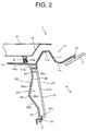
- Fig. 2 is a cross-sectional view showing a cross-section of the cowl top cover according to the present first embodiment.
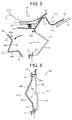
- Figs. 3 and 4 are perspective views of a cover section of the cowl top cover seen obliquely from the front and rear sides.
- the front and rear direction means a vehicle length direction, the direction in which the vehicle moves frontward is set as “frontward”, and the direction in which the vehicle moves backward is set as “rearward”.
- the left and right direction means a vehicle width direction, and the left-hand and right-hand directions when the driver faces frontward are respectively set as “leftward” and “rightward”.
- the vertical direction means a vehicle height direction, the direction on the ground side of the vehicle is set as “downward”, and the direction on the opposite side is set as "upward”.
- thewindshield3 is disposed in front of the cabin, and the hood 4 is openably and closably disposed so as to cover the upper side of the engine room in the front section of the vehicle body.
- the windshield 3 is disposed upward inclined from the front end toward the rear end.
- a pair of left and right windshield wipers 5 are disposed, and these windshield wipers 5 are rotatably attached onto the glass surface of the windshield 3 by a not-shown drive motor.
- a cowl section 6 opened upward is disposed between the hood 4 and the windshield 3, and an air intake section configured to introduce the outside air into the cabin of the air conditioner (not shown) is connected to the cowl section 6.
- an air intake section configured to introduce the outside air into the cabin of the air conditioner (not shown) is connected to the cowl section 6.
- the cowl top cover 10 of the present first embodiment is attached to the vehicle body so as to be along the vehicle width direction. It shouldbe noted that the mount ing structure of the cowl top cover 10 with respect to the vehicle body can employ a commonly known conventional mounting structure.
- the cowl top cover 10 of the present first embodiment is formed by injection molding a thermoplastic resin such as polypropylene, an acrylonitrile-butadiene-styrene copolymer, and a polyamide-based synthetic resin. It should be noted that in the invention, the material of the cowl top cover 10 is not particularly limited, and can be arbitrarily selected.
- the cowl top cover 10 includes, as shown in the Fig. 2 , a cover body section 11 configured to cover the cowl section 6, a cover rear end section 12 disposed on the rear end side of the cover body section 11 and secured to the windshield 3, a vertical wall section 13 suspended from the front end section of the cover body section 11 so as to partition the space between the engine room and the cowl section 6 , an upper extending section 14 extending frontward from the upper end section of the vertical wall section 13, and a panel fixing section 15 disposed in the lower end section of the vertical wall section 13 and fixed to the support section of the vehicle body panel 2.
- the cover body section 11 of the cowl top cover 10 is configured to include a first bent section 11a bent in a valley shape, and a second bent section 11b bent in a ridge shape in the region between the cover rear end section 12 and the front vertical wall section 13, and the first and second bent sections 11a and 11b are formed throughout in the vehicle width direction.
- a grid-like air intake port (inlet port) 11c for introducing outside air into the vehicle body is disposed in a predetermined region in the vehicle width direction of the cover body section 11.
- the upper extending section 14 of the cowl top cover 10 includes an extending body section 14a linearly extended frontward from the upper end section of the front vertical wall section 13, and a seal member fixing section 14b disposed on the top surface of the extending body section 14a.
- An elastically deformable seal member 8 is fixed to the seal member fixing section 14b of the upper extending section 14 by adhesion or the like.
- the seal member 8 is formed so as to have a hollow shape by using rubber or a thermoplastic elastomer, and the seal member 8 is disposed in a predetermined position, whereby when the hood 4 is closed, the seal member 8 is pressed against the reinforcement 4a disposed on the rear surface side of the hood 4, and can seal the space between the upper extending section 14 of the cowl top cover 10 and the hood 4. This prevents the hot air and odor from the engine room from leaking out on the upper surface side of the cover body section 11 through the space between the upper extending section 14 and the hood 4.
- the vertical wall section 13 of the cowl top cover 10 includes a vertical wall body 21 to be the vertical wall section body, an opening 22 formed in a central section in the vehicle width direction in the vertical wall body 21, and a cover section 3 0 having a shape and dimension to cover the opening 22 , attachable to and detachable from the vertical wall body 21.
- the vertical wall body 21 is formed in a flat plate shape in the present first embodiment. It should be noted that the vertical wall body 21 may be formed by part of the vertical wall body 21 being partially swelled frontward in association with the shape of the swelling section 32 described below of the cover section 30.
- the vertical wall body 21 includes a frame section 21a formed around the opening 22, a first engaging section (not shown in Fig. 2 ) disposed in the upper side section of the frame section 21a and to be engaged with the insertion claw section 33 described below of the cover section 30, and a second engaging section (not shown in Fig. 2 ) disposed in the lower side section of the frame section 21a and to be engaged with the hold claw section 34 described below of the cover section 30.
- the first engaging section includes a locking wall section suspended from the upper side section of the frame section 21a in the position corresponding to the insertion claw section 33 of the cover section 30.
- the second engaging section includes a base section extending from the lower side section of the frame section 21a in the position corresponding to the hold claw section 34 of the cover section 30, and a recessed notch section formed at the tip section of the base section, fitting the hold claw section 34.
- a recessed groove section 21b is recessed along the vehicle width direction.
- the recessed groove section 21b constitutes a vertical wall side deformation promotion section configured to prompt the vertical wall body 21 to bend and deform in the desired behavior, and the recessed groove section 21b is formed, whereby, as described below, when the cowl top cover 10 receives an impact, the vertical wall body 21 can be stably bent and deformed in the behavior such that the vertical wall body 21 is crushed in the vehicle height direction while the substantially central section in the vertical direction in the vertical wall body 21 is displaced rearward (see Fig. 5 ).
- the position of the recessed groove section 21b formed as a vertical wall side deformation promotion section in the vertical wall body 21 and the dimensions such as the groove width and the groove depth of the recessed groove section 21b are not particularly limited, and can be changed arbitrarily depending on the form of the cowl top cover 10 and the model and the like of the vehicle 1 where the cowl top cover 10 is used.
- the opening 22 formed in the vertical wall body 21 has a substantially rectangular shape in the front view, and through theopening22, it is possible, for example, to visually recognize the indication such as the chassis number engraved on the plate disposed in the rear of the vertical wall section 13 and to perform the maintenance on the electrical system components and the like disposed in the rear of or below the vertical wall section 13. It should be noted that in the invention, the shape and dimensions of the opening 22 can be arbitrarily changed.
- the cover section 30 configured to block the opening 22 includes as shown in Figs. 3 and 4 , a cover section body 31 substantially disposed in parallel to the vertical wall body 21 in the upper end section and the lower end section of the cover section 30, and a swelling section 32 configured to swell frontward in a V-shape with respect to the cover section body 31.
- These cover section body 31 and the swelling section 32 have plate thicknesses of a predetermined size such that the vertical wall section 13 can secure the desired strength when the cover section 30 is attached to the vertical wall body 21.
- the swelling section 32 is formed along the vehicle width direction, and includes an upper inclined section 32a inclined downward from the boundary section with the upper cover section body 31 toward the front, and a lower inclined section 32b inclined upward from the boundary section with the lower cover section body 31 toward the front, and in addition, the front end section (tip section) of the upper inclined section 32a and the front end section (tip section) of the lower inclined section 32b are connected to constitute a ridge section 32c.
- the ridge section 32c is disposed over the entire region in the vehicle width direction in the cover section 30.
- the ridge section 32c in the present first embodiment is disposed slightly lower than the height position of the center line in the vertical direction of the cover section 30. The ridge section 32c is thus disposed, whereby when the vertical wall section 13 receives a stress (load) in the direction of being crushed, the stress can be most effectively focused on the swelling section 32.
- the swelling section 32 constitutes a cover-side bending promotion section configured to prompt the cover section 30 to bend and deform in the desired behavior, and the cover section 30 includes the swelling section 32, whereby, as described below, when the cowl top cover 10 receives an impact, the entire cover section 30 can be bent and deformed in such behavior as to be crushed in the vehicle height direction while the swelling section 32 is displaced frontward.
- the recessed groove section 32d is recessed along the vehicle width direction as the cover-side bending promotion section.
- the recessed groove section (cover-side bending promotion section) 32d is disposed along the ridge section 32c, whereby when the cover section 30 bends and deforms by being prompted by the swelling section 32 being the cover-side bending promotion section, the swelling section 32 is more easily bent, and the bending deformation of the cover section 30 can be caused more effectively and stably.
- the formation of the recessed groove section 32d disposed along the ridge section 32c may be omitted, for example, when the strength of the cover section 30 is increased.
- each of the locking claws 33 protrude rearward to be disposed.
- a locking claw 33a caught to be engageable with the first engaging section disposed on the upper side section of the vertical wall body 21 with the elastic deformation is formed in a hook-shape.
- each of the locking claws 33a is formed in the shape and dimensions for releasing the engaging state with the first engaging section of the vertical wall body 21 and being disengageable from the first engaging section when the vertical wall body 21 and the cover section 30 receive the impact to be bent and deformed.
- two hold claw sections 34 protrude rearward in a substantially L-shape to be disposed, and hold the second engaging section disposed in the lower side section of the vertical wall body 21, whereby the two hold claw sections 34 can be engaged with the second engaging section.
- the left and right insertion claw sections 33 and the left and right hold claw sections 34 are disposed in the positional relation of being arranged vertically so that the relative positions in the vehicle width direction correspond to each other.
- the hold claw section 34 of the cover section 30 is hooked to be held in the second engaging section of the vertical wall body 21 while the cover section 30 is aligned with respect to the vertical wall body 21 and the opening 22. Then, the cover section 30 is rotated toward the vertical wall body 21 with the hold claw section 34 as an axis, and the insertion claw section 33 of the cover section 30 is inserted into the opening 22. At this time, while the locking claw 33a of the insertion claw section 33 is elastically deformed, the insertion claw section 33 is in sliding contact with the frame section 21a of the vertical wall body 21.
- the cover section 30 is pushed into the vertical wall body 21, whereby the locking claw 33a is elastically returned, and the insertion claw section 33 is engaged with the first engaging section of the vertical wall body 21.
- the cover section 30 is attached to the vertical wall body 21 in such a manner as to cover the opening 22.
- the swelling section 32 of the cover section 30 is, as described above, disposed throughout the entire region in the vehicle width direction in the cover section 30, and therefore in the cover section 30, the forming region in the vehicle width direction where the left and right insertion claw sections 33 and hold claw sections 34 are formed is included in the forming region in the vehicle width direction of the swelling section 32.
- the positional relation between the left and right insertion claw sections 33 and hold claw sections 34 and the swelling section 32 is thus set, whereby when the vertical wall body 21 receives an impact to receive a stress (load) in the direction of being crushed, the stress can be effectively caused to act on the swelling section 32 through the insertion claw section 33 and the hold claw section 34 of the cover section 30.
- a reinforcement lateral rib 35a disposed along the lateral direction so as to connect the two insertion claw sections 33, and three reinforcement vertical ribs 35b disposed along the vertical direction and connected to the reinforcement lateral rib 35a are disposed.
- the reinforcement lateral rib 35a in the present first embodiment is erected rearward from the rear surface on the upper end section side of the cover section body 31, and has a plurality of curved sections curved vertically with respect to the lateral direction, and is disposed so as to undulate slightly vertically.
- the reinforcement vertical rib 35b has its upper end connected to the reinforcement lateral rib 35a, and is disposed from the upper end section side of the cover section body 31 to the lower end section side of the cover section body 31 through the swelling section 32.
- This reinforcement vertical rib 35b is formed so as to follow the cross-sectional shape of the cross section perpendicular to the lateral direction in the cover section body 31 and the swelling section 32, and when each of the reinforcement vertical ribs 35b is viewed from the lateral side surface side, the central portion in the vertical direction in the reinforcement vertical rib 35b has a form bent in a V-shape so as to protrude frontward.
- Each of the reinforcement vertical ribs 35b has this form, whereby when the cover section 30 is prompted by the cover-side bending promotion section to bend and deform, the reinforcement vertical rib 35b can also be stably bent and deformed along with the swelling section 32.
- two handle sections 36 are disposed so as to protrude frontward.
- the operator pulls the handle sections 36 of the cover section 30 while pressing the handle sections 36 down by hand, whereby the engaging state between the insertion claw section 33 of the cover section 30 and the first engaging section of the vertical wall body 21 can be released, and furthermore, the cover section 30 can be rotated to the front side with the hold claw section 34 as an axis.
- the operator further pulls the cover section 3 0 by grasping the handle section 3 6, whereby the hold claw section 34 of the cover section 30 is detached from the second engaging section of the vertical wall body 21, and the cover section 30 can be removed from the vertical wall body 21.
- a cushioning material (not shown) with elasticity may also be fixed on the rear surface of the part overlapping with the vertical wall body 21 of the cover section 30 when the cover section 30 is attached to the vertical wall body 21.
- This cushioning material is attached, whereby the cover section 30 can be made difficult to scratch or damage due to the contact with the vertical wall body 21.
- the gap formed between the cover section 30 and the vertical wall body 21 in particular, the gap formed between the swelling section 32 of the cover section 30 and the frame section 21a of the vertical wall body 21
- the sealing performance between the cover section 30 and the vertical wall body 21 can be increased.
- the cowl top cover 10 in the present first embodiment having the configuration described above, in a state where the cover section 30 is attached to the vertical wall body 21 in such a manner as to cover the opening 22, for example, when the object 9 collides with the hood 4 (or the cowl top cover 10) from the upper surface side, as shown in Fig. 5 , the hood 4 receives an impact force (an impact load) N from above by the object 9.
- the hood 4 receiving the impact forceNde forms so as to narrow the space with the reinforcement 4a, and causes the seal member 8 to compress.
- the cowl top cover 10 also receives the impact force of the object 9 from the upper side through the hood 4 and the seal member 8, and causes the cover body section 11 and the upper extending section 14 to be displaced downward.
- the panel fixing section 15 disposed in the lower end section of the vertical wall section 13 is fixed by the support section of the vehicle body panel 2 to be supported, and therefore the vertical wall section 13 of the cowl top cover 10 is deformed in a manner so as to be crushed so as to reduce the height dimension in the vertical direction.
- the vertical wall body 21 of the vertical wall section 13 includes the recessed groove section 21b constituting the vertical wall side deformation promotion section in a substantially central section in the vertical direction, and therefore, is buckled in the central part where the recessed groove section 21b is formed when receiving a certain size or more of the impact force N, and can be stably bent and deformed in a manner so as to be crushed in the vertical direction while causing the central part to be displaced rearward.
- the cover section 30 engaged with the vertical wall body 21 receives the stress in the direction of reducing the height dimension in the vertical direction from the vertical wall body 21 through the left and right insertion claw sections 33 and hold claw sections 34.
- the swelling section 32 constituting the cover-side bending promotion section along the lateral direction swells frontward, and therefore the received stress acts on the swelling section 32, whereby the swelling section 32 is buckled, and can be stably bent and deformed in a manner so as to be crushed in the vertical direction while the ridge section 32c of the swelling section 32 is displaced frontward.
- the locking claw 33a of the insertion claw section 33 is, as described above, configured to be detached from the first engaging section of the vertical wall body 21 when the cover section 30 is bent and deformed, and the ridge section 32c of the swelling section 32 moves frontward by the frontward swelling of the swelling section 32 during the bending deformation of the cover section 30.
- the cover section 30 releases the engagement between the insertion claw section 33 and the hold claw section 34 and the first and second engaging sections of the vertical wall body 21, and can be easily removed from the vertical wall body 21 to be disengaged (drop) frontward.
- the reduction in the bending promotion due to the cover section 30 remaining while being engaged with the vertical wall body 21 can be prevented, and the deformation of the vertical wall section 13 can be stably promoted.
- the cowl top cover 10 of the present first embodiment when the impact force N from the upper side is received, irrespective of the collision position and the collision direction of the object 9, the vertical wall body 21 of the vertical wall section 13 and the cover section 30 are bent and deformed in the direction of being separated from each other, and furthermore the cover section 30 can be removed from the vertical wall body 21 to be separated. For this reason, when the vertical wall body 21 and the cover section 3 0 are crushed, the cover section 30 is prevented from interfering with the bending deformation of the vertical wall body 21, and the cover section 30 and the vertical wall body 21 can be stably and reliably crushed so that the height dimension is reduced, and therefore the hood 4 can be displaced further downward. Therefore, in the cowl top cover 10 of the present first embodiment, an excellent impact absorption function can be stably exhibited.
- the magnitude of the impact the object 9 receives by the collision with the hood 4 can be effectively absorbed to be relaxed by the deformation of the hood 4, seal member 8, and the cowl top cover 10, as described above, and therefore the damage the object 9 receives can be reduced as much as possible, and the object 9 can be protected.
- the vertical wall body 21 of the vertical wall section 13 is, as described above, linearly suspended from the cover body section 11 with a predetermined plate thickness, and the recessed groove section 21b is recessed in the substantially central section in the vertical direction of the vertical wall body 21.
- the configuration of the vertical wall body in the vertical wall section is not limited thereto, and if the predetermined strength of the vertical wall section can be secured, and the deformation of the vertical wall body can smoothly proceed without being inhibited by the cover section when the vertical wall body receives the stress to be deformed in a manner so as to be crushed, the vertical wall body may employ other configurations.
- the vertical wall body 41 includes an upper half section 41a extending linearly downward from the cover body section 11, a lower half section 41b disposed to be rearward shifted substantially in parallel with the upper half section 41a, and a connecting section 41c connecting between the lower end section of the upper half section 41a and the upper end section of the lower half section 41b in a crank shape in the cross-sectional view in Fig. 6 .
- the connecting section 41c is formed throughout in the vehicle width direction of the vertical wall section 13 , and is configured as the vertical wall side deformation promotion section (breaking section) configured to break and to prompt the deformation of the vertical wall body 41 when the vertical wall body 41 receives a certain magnitude or more of the impact load from the upper side.
- the vertical wall side deformation promotion section breaking section
- the connecting section 41c of the vertical wall body 41 breaks, and the upper half section 41a and the lower half section 41b of the vertical wall body 41 are separated, and furthermore, the divided upper half section 41a descends on the front side of the lower half section 41b, whereby the vertical wall body 41 can be deformed in a manner so as to be crushed in the vertical direction.
- the cover section 30 engaged with the vertical wall body 41 can be bent and deformed in a manner so as to be crushed in the vertical direction while displacing the ridge section 32c of the swelling section 32 frontward, and furthermore, removed from the vertical wall body 41 to be detached frontward.
- the cowl top cover 10a having a difference in the form of the vertical wall body 41 from the vertical wall body 21 in the above-described first embodiment can prevent the cover section 30 from interfering with the deformation of the vertical wall body 41, and can crush the cover section 30 and the vertical wall body 41 stably and reliably so that the height dimension is reduced, and therefore the excellent impact absorption function can be stably exhibited.
- the vertical wall body 42 shown in Fig. 7 includes an upper half section 42a extending linearly downward from the cover body section, a lower half section 42b disposed in parallel on the lower side of the upper half section 42a, and a connecting section 42c connecting the upper half section 42a and the lower half section 42b, and as described below, the connecting section 42c constitutes the vertical wall side deformation promotion section configured to break to prompt the deformation of the vertical wall body 42.
- the lower end surface of the upper half section 42a and the upper end surface of the lower half section 42b are formed on the inclined surfaces inclined downward and frontward, and the upper half section 42a and the lower half section 42b are connected vertically through the connecting section 42c in a state where each of the inclined surfaces is combined with each other.
- the connecting section 42c connecting the upper half section 42a and the lower half section 42b includes an elastically deformable tongue piece section 42d extended from the rear surface of the lower end section of the upper half section 42a, and a locking protrusion section 42e protruded on the rear side of the upper end section of the lower half section 42b, and a locking hole 42f for inserting the locking protrusion section 42e is bored in the tongue piece section 42d.
- the locking protrusion section 42e of the connecting section 42c includes an engaging head section 42g formed by the tip section of the locking protrusion section 42e being crushed while being heated toward the tongue piece section 42d side after the locking protrusion section 42e is inserted into the locking hole 42f of the tongue piece section 42d to be held in a state of the tongue piece section 42d being hooked, and the tongue piece section 42d is held so as not to be removed from the locking protrusion section 42e by the engaging head section 42g.
- the upper half section 42a and the lower half section 42b of the vertical wall body 42 are separated, and furthermore, the divided upper half section 42a descends while moving on the front side of the lower half section 42b, whereby the vertical wall body 42 can be easily deformed in a manner so as to be crushed in the vertical direction. Therefore, even in the cowl top cover including the vertical wall body 42 according to the modification, an excellent impact absorption function can be stably exhibited.
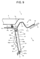
- Fig. 9 is a cross-sectional view showing a cross-section of the cowl top cover according to the second embodiment of the invention.
- Figs. 10 and 11 are perspective views of a cover section of the cowl top cover seen obliquely from the front and rear sides. It should be noted that in the present second embodiment and the third embodiment described below, although the form of the cover section of the cowl top cover is different, the configuration other than the cover section is substantially the same as those in the cowl top cover in the above-described first embodiment, and therefore the description will be made by focusing on the cover section, and the same member as in the first embodiment described above will be represented by using the same reference numerals, whereby the detailed description will be omitted.
- the vertical wall section 13 of the cowl top cover 10b in the present second embodiment includes a vertical wall body 21, an opening 22 formed in the vertical wall body 21, and a cover section 50 attachable to and detachable from the vertical wall body 21.
- the vertical wall body 21 includes a frame section 21a formed around the opening 22, a first engaging section 21c disposed in the upper side section of the frame section 21a and to be engaged with the insertion claw section 53 described below of the cover section 50, and a second engaging section 21d disposed in the lower side section of the frame section 21a and to be engaged with the hold claw section 54 described below of the cover section 50.
- the first engaging section 21c includes a locking wall section suspended from the upper side section of the frame section 21a in the position corresponding to the insertion claw section 53 of the cover section 50.
- the second engaging section 21d includes a base section extending from the lower side section of the frame section 21a in the position corresponding to the hold claw section 54 of the cover section 50, and a recessed notch section formed at the tip section of the base section, fitting the hold claw section 54.
- the recessed groove section 21b to be the vertical wall side deformation promotion section is recessed along the vehicle width direction.
- the cover section 50 in the present second embodiment includes a cover section body 51, and a swelling section 52 configured to swell in a V-shape on the front side with respect to the cover section body 51 when the cross section perpendicular to the vehicle width direction is viewed.
- the swelling section 52 in the present second embodiment is disposed in a partial region on the central side in the vehicle width direction of the cover section 50, and the swelling section 52 is not disposed on the left and right side edge section side of the cover section 50, and the flat cover section body 51 is disposed.
- the swelling section 52 constitutes a cover-side bending promotion section configured to prompt the cover section 50 to bend and deform in the desired behavior, and the cover section 50 includes the swelling section 52, whereby, as with the cover section 30 in the above first embodiment, when the cowl top cover 10b receives an impact, the entire cover section 50 can be bent and deformed in such behavior as to be crushed in the vehicle height direction while the ridge section 52d of the swelling section 52 is displaced frontward.
- the swelling section 52 is disposed so that the maximum dimension in the vehicle width direction of the swelling section 52 has the magnitude of 30% ormore, inparticular 50% or more, of the dimension in the vehicle width direction of the entire cover section 50.
- the swelling section 52 is provided in this range, whereby when the vertical wall body 21 is deformed inamanner so as to be crushed, the bending deformation of the cover section 50 can be effectively promoted, and the cover section 50 can be stably crushed.
- the swelling section 52 includes an upper inclined section 52a inclined downward and frontward from the boundary section with the cover section body 51 on the upper side, a lower inclined section 52b inclined upward and frontward from the boundary section with the cover section body 51 on the lower side, and a gradually decreasing section 52c disposed on both left and right sides of the upper and lower inclined sections 52a and 52b, causing the frontward swelling amount with respect to the cover section body 51 to gradually decrease toward the left and right side edge sides of the cover section 50, and the entire swelling section 52 is formed so as to protrude in a tent shape with respect to cover section body 51.
- a ridge section 52d is formed between the upper and lower inclined sections 52a and 52b in the swelling section 52, and the ridge section 52d is disposed slightly lower than the height position of the center line in the vertical direction of the cover section 50.
- the recessed groove section 52e is recessed along the vehicle width direction at the same height as the ridge section 52d as the cover-side bending promotion section, and constitutes the cover section 50 (in particular, the swelling section 52 and the cover section body 51) easier to bend, along with the swelling section 52 to be the cover-side bending promotion section.
- the cover section 50 in the present second embodiment includes, as with the cover section 30 in the above first embodiment, two insertion claw sections 53 protruding rearward from the rear surface of the upper end section of the cover section 50, two hold claw sections 54 protruding substantially in an L-shape rearward from the rear surface of the lower end section of the cover section 50, a reinforcement lateral rib 55a and a reinforcement vertical rib 55b erected on the rear surface of the cover section 50, and two handle sections 56 disposed on the front surface of the upper end section of the cover section 50.
- the left and right insertion claw sections 53 and hold claw sections 54 are disposed so that the forming region in the vehicle width direction is included within the forming region in the vehicle width direction of the swelling section 52 formed in a tent shape.
- the left and right insertion claw sections 53 and hold claw sections 54 are disposed so as to correspond to the positions of the left and right ends of the swelling section 52 in the vehicle width direction.
- the cowl top cover 10b including the cover section 50 in the present second embodiment when receiving the impact force from the upper side, can bend and deform the vertical wall body 21 of the vertical wall section 13 and the cover section 50 in the direction of separating them from each other, and furthermore, can remove the cover section 50 from the vertical wall body 21 to separate.
- the cover section 50 canbeprevented from interfering with the bending deformation of the vertical wall body 21, and the cover section 50 and the vertical wall body 21 can be stably and reliably crushed so that the height dimension is reduced. Therefore, even in the cowl top cover 10b according to the present second embodiment, an excellent impact absorption function can be stably exhibited.
- the swelling section 52 is disposed in a partial region on the central side in the vehicle width direction of the cover section 50 , and the flat cover sectionbody 51 is disposed on the left and right side edge sections of the cover section 50.
- the cover section 50 when the cover section 50 is engaged with the vertical wall body 21 in such a manner as to block the opening 22 of the cowl top cover 10b, it can be an easily continuous surface with the flat formed vertical wall section 13, and therefore the appearance can be improved.
- the sealing performance of the vertical wall body 21 can be easily increased, and therefore the hot air and odors from the engine room can be effectively prevented from entering the cowl section through the opening 22.
- Fig. 12 is a perspective view of a cover section of the cowl top cover seen obliquely from the front side according to the present third embodiment.
- the cover section 60 in the present third embodiment includes a cover section body 61, and two swelling sections 62 configured to swell in a V-shape on the front side with respect to the cover section body 61 when the cross section perpendicular to the vehicle width direction is viewed.
- the two swelling sections 62 in the present third embodiment are bilaterally symmetrically formed with respect to the center line in the vehicle width direction of the cover section 60, and a flat cover section body 61 is disposed in the region on the left and right side edge sides of the cover section 60 and in the region between the two swelling sections 62.
- the left and right two swelling sections 62 are disposed so that the sum of the maximum dimension in the vehicle width direction of each of the swelling sections 62 has the magnitude of 30% or more, in particular 50% or more, of the dimension in the vehicle width direction of the entire cover section 60.
- each of the left and right swelling sections 62 includes an upper inclined section 62a inclined downward and frontward from the boundary section with the cover section body 61 on the upper side, a lower inclined section 62b inclined upward and frontward from the boundary section with the cover section body 61 on the lower side, and a gradually decreasing section 62c disposed on both left and right sides of the upper and lower inclined sections 62a and 62b, and each of the swelling sections 62 is formed so as to protrude in a tent shape with respect to the cover section body 61.
- a ridge section 62d is formed in the substantially central section in the vertical direction of each of the swelling sections 62, and the ridge section 62d is disposed slightly lower than the height position of the center line in the vertical direction of the cover section 60.
- Each of the left and right swelling sections 62 constitutes a cover-side bending promotion section configured to prompt the cover section 60 to bend and deform in the desired behavior, and the cover section 60 includes the two swelling sections 62, whereby when the cowl top cover receives an impact, the entire cover section 60 can be bent and deformed in such behavior as to be crushed in the vehicle height direction while the ridge section 62d of the swelling section 62 is displaced frontward.
- the recessed groove section 62e is recessed along the vehicle width direction at the same height as the ridge section 62d as the cover-side bending promotion section, and constitutes the cover section 60 (in particular, the swelling section 62 and the cover section body 61) easier to bend, along with the swelling section 62 to be the cover-side bending promotion section.
- the cover section 60 in the present third embodiment includes, as with the cover sections 30 and 50 in the above first and second embodiments, left and right insertion claw sections and hold claw sections (not shown), and a reinforcement lateral rib and a reinforcement vertical rib on the rear surface side of the cover section 60, and two handle sections 66 disposed on the front side of the cover section 60.
- the left and right insertion claw sections and hold claw sections are disposed so that the forming region in the vehicle width direction is included within the forming region in the vehicle width direction of the left and right swelling sections 62 formed in a tent shape.
- the cowl top cover including the cover section 60 in the present third embodiment when receiving the impact force from the upper side, can bend and deform the vertical wall body 21 of the vertical wall section 13 and the cover section 60 in the direction of separating them from each other, and furthermore, can remove the cover section 60 from the vertical wall body 21 to separate.
- the cover section 60 can be prevented from interfering with the bending deformation of the vertical wall body 21, and the cover section 60 and the vertical wall body 21 can be stably and reliably crushed so that the height dimension is reduced. Therefore, even in the cowl top cover according to the present third embodiment, an excellent impact absorption function can be stably exhibited.
- the cover section 60 in the present third embodiment can improve the appearance of the vertical wall section 13.
- the sealing performance of the vertical wall body 21 can be increased, and therefore the hot air and odors from the engine room can be effectively prevented from entering the cowl section through the opening 22.
Landscapes
- Engineering & Computer Science (AREA)
- Mechanical Engineering (AREA)
- Chemical & Material Sciences (AREA)
- Combustion & Propulsion (AREA)
- Transportation (AREA)
- Body Structure For Vehicles (AREA)
- Vehicle Interior And Exterior Ornaments, Soundproofing, And Insulation (AREA)
- Superstructure Of Vehicle (AREA)
Abstract
Description
- The invention relates to a cowl top cover configured to cover a cowl section disposed between a windshield and a hood of a vehicle.
- For example, in
JP 2011-5988 A - According to the cowl top cover structure of the
Patent Document 1, when the vertical wall section of the cowl top cover is deformed in a manner so as to be crushed from the upper side, the upper side of the opening in the vertical wall section is made to slide with respect to the inclined side of the cover section, and the rotational moment of the cover section around the hook section of the vertical wall section disposed at the bottom of the cover section is acted. As a result, the cover section that has blocked the opening to support is removed from the vertical wall section, and the vertical wall section can be easily deformed, and therefore the impact absorption performance in the cowl top cover, for example, when an object collides with the hood and the like can be improved. - Patent Document 1:
JP 2011-5988 A - In the cowl top cover structure described in
Patent Document 1, the elevation surface of the cover section attached to the vertical wall section so as to block the opening coincides with the standing direction of the vertical wall section. In this case, when, for example, an object (collision object) collides with the position as shown inFig. 4 inPatent Document 1, the upper side of the opening slides with respect to the inclined side of the rib disposed in the cover section, and the cover section is relatively pushed frontward, whereby the cover section is tilted toward the front of the vehicle to be removed from the vertical wall section. Thus, the support of the opening is released, and the vertical wall section can be easily deformed. - However, when an object collides, for example, from a direction along the position of the elevation surface of the cover section, the effect of sliding the upper side of the opening with respect to the inclined side of the cover section is weakened, and the direction of the elevation surface of the cover section matches the downward direction of the collision object, and therefore there is a concern that the cover section supports the vertical wall section.
- In addition, when an inclined side is tried to be configured such that, for example, the cover section is removed more easily so as to reduce the above concern, it is necessary to take measures to adjust the angle of the inclined side in accordance with the shape of the vehicle, and to optimize the shape of the rib where the inclined side is disposed. Therefore, the production cost is increased, and the design limitations such as the rib and the like being made relatively larger, the cover section being made relatively smaller, or the opening being arranged in the lower part of the vertical wall section occur, and therefore there is a problem that it is difficult to configure the cover section and the opening so that the usability is improved.
- The invention is made in view of the above conventional problem, and the specific object is to provide a cowl top cover preventing the cover section configured to block the opening of the vertical wall section from inhibiting the effect of the vertical wall section collapsing to reduce the height dimension, and capable of stably exhibiting the effect of absorbing the impact the object receives, even when the object collides with a wider range in the rear end section of the hood.
- To achieve the above object, the cowl top cover provided by the invention is most mainly characterized in that the cowl top cover includes a cover body section configured to cover a cowl section disposed between a windshield and a hood of a vehicle, and a vertical wall section suspended from one end section of the cover body section; the vertical wall section includes a vertical wall body, at least one opening formed in the vertical wall body, and a cover section configured to cover the opening, attachable to and detachable from the vertical wall body; and the cover section includes a cover-sidebendingpromotion section disposed along a vehicle width direction, configured to prompt bending deformation on one side in a vehicle length direction.
- In the cowl top cover according to the invention, the cover-side bending promotion section preferably includes a swelling section configured to swell on one side in a vehicle length direction.
- In this case, the swelling section preferably swells in a V-shape. In addition, the swelling section preferably swells frontward in a vehicle length direction.
- In addition, in the cowl top cover according to the invention, the swelling section of the cover section is preferably disposed in a central region in a vehicle width direction in the cover section, and in a peripheral section of the swelling section, a flat cover section body is preferably disposed along the vertical wall body. Furthermore, a maximum dimension in a vehicle width direction of the swelling section is preferably set to 30% or more of a dimension in a vehicle width direction of the cover section.
- Furthermore, in the cowl top cover according to the invention, the swelling section preferably includes an upper inclined section and a lower inclined section inclined toward one side in a vehicle length direction from the cover section body, and a gradually decreasing section disposed on both left and right sides of the upper inclined section and the lower inclined section, the gradually decreasing section causing a swelling amount with respect to the cover section body to gradually decrease toward the left and right side edge sides of the cover section.
- In this case, a ridge section between the upper inclined section and the lower inclined section in the swelling section is preferably disposed lower than a height position of a center line in a vehicle height direction of the cover section along a vehicle width direction.
- In addition, a recessed groove section is preferably recessed on a surface facing the other side in a vehicle length direction in the cover section body and the swelling section, and the recessed groove section is preferably disposed corresponding to the height position where the ridge section between the upper inclined section and the lower inclined section in the swelling section is disposed.
- Furthermore, in the cowl top cover according to the invention, an upper side claw section and a lower side claw section engageable with and disengageable from the vertical wall body are respectively disposed in an upper end section and a lower end section of the cover section preferably, and the upper side claw section and the lower side claw section are preferably disposed in a position corresponding to a forming region of the swelling section in a vehicle width direction, and in a position corresponding to an end section of the swelling section.
- Furthermore, in the cover section of the cowl top cover according to the invention, at least one reinforcement vertical rib is preferably disposed, and the reinforcement vertical rib preferably has a bent form so as to protrude in a direction where the cover-side bending promotion section prompts bending deformation.
- The cowl top cover according to the invention includes a cover body section configured to cover the cowl section, and a vertical wall section suspended from one end of the cover body section; and the vertical wall section includes a vertical wall body, at least one opening formed in the vertical wall body, and a cover section configured to cover the opening, attachable to and detachable from the vertical wall body. In addition, the cover section of the vertical wall section includes a cover-side bending promotion section configured to promote the bending deformation along the vehicle width direction of the cover section on one direction side in the vehicle length direction (for example, frontward).
- If the cowl top cover includes this cover section, when the cowl top cover receives an impact by an object colliding from above with, for example, the cowl top cover and a wide range of the hood, the vertical wall body of the vertical wall section deforms in a manner so as to be crushed by the impact force (impact load) regardless of the collision position and the collision direction of the object, and the cover-side bending promotion section promotes the bending deformation of the cover section effectively, and the entire cover section can be deformed in a manner so as to be crushed in the vehicle height direction while part of the cover section is displaced so as to protrude toward one of the vehicle length direction.
- Thus, the bending deformation of the cover section is guided in a predetermined direction to proceed by the cover-side bending promotion section, whereby the cover section can crush the cover section and the vertical wall body stably so that the height dimension is reduced without inhibiting the deformation of the vertical wall body, and furthermore the action of the cover section coming off the vertical wall body can be promoted. Thus, the reaction force acting on the object colliding with the cowl top cover and the hood is reduced, and the impact the object receives can be absorbed effectively to be relaxed, and therefore the sufficient impact absorption function can be stably obtained.
- In the cowl top cover of the invention, the cover-side bending promotion section includes a swelling section swelling on one side of the vehicle length direction. As a result, when the vertical wall body of the vertical wall section is deformed in a manner so as to be crushed, the bending deformation of the cover section is effectively promoted by the swelling section, and the cover section can be stably crushed.
- In this case, the swelling section swells in a V-shape, whereby the bending deformation of the cover section can be promoted more effectively.
- In addition, the swelling section swells frontward in the vehicle length direction, whereby when the vertical wall body of the vertical wall section is deformed in a manner so as to be crushed, the cover section can be stably bent and deformed frontward in the vehicle length direction. Furthermore, when the cover section is removed from the vertical wall body, if the swelling section swells frontward in the vehicle length direction, the cover section can be easily removed to drop frontward in the vehicle length direction.
- Thereby, it can be prevented that the cover section remaining while engaged with the vertical wall body cannot promote the deformation of the vertical wall body. In particular, the swelling direction of the swelling section for swelling in a V-shape is directed frontward in the vehicle length direction, whereby the cover section can be more effectively bent and deformed frontward in the vehicle length direction, and the cover section can be more easily removed to drop from the vertical wall body frontward in the vehicle length direction.
- In addition, in the cowl top cover of the invention, the swelling section of the cover section is disposed in the central region in the vehicle width direction in the cover section, and the flat-plate-shaped cover section body is disposed along the vertical wall body on the periphery of the swelling section. As a result, when the cover section is engaged with the vertical wall body, the sealing performance between the cover section and the vertical wall body can be enhanced, and the cover section body of the cover section and the vertical wall body are disposed substantially in parallel, and can be made to appear like a continuous surface, and therefore the quality of appearance (appearance) of the vertical wall section can be improved.
- Furthermore, the maximum dimension in the vehicle width direction of the swelling section is set to be 30% or more of the dimension in the vehicle width direction of the cover section, preferably 50% or more. The swelling section having a width dimension of this range is provided, whereby when the vertical wall body is deformed in a manner so as to be crushed in the vehicle height direction, the bending deformation of the cover section can be effectively promoted, and the cover section can be stably crushed.
- Furthermore, the swelling section includes an upper inclined section and a lower inclined section inclined toward one side in a vehicle length direction from the cover section body, and a gradually decreasing section disposed on both left and right sides of the upper inclined section and the lower inclined section, causing a swelling amount with respect to the cover section body to gradually decrease toward the left and right side edge sides of the cover section. The swelling section of the cover section is thus configured, whereby the swelling section can be efficiently provided in a central region in the vehicle width direction in the cover section, and the quality of appearance of the cover section (appearance) can be improved.
- In this case, a ridge section between the upper inclined section and the lower inclined section in the swelling section is disposed lower than a height position of a center line in a vehicle height direction of the cover section along a vehicle width direction. As a result, when the vertical wall section receives the stress (load) in the direction of being crushed, the stress can be effectively focused on the swelling section of the cover section, and the bending deformation of the cover section can be stably promoted.
- In addition, the recessed groove section is recessed on the surface facing the other side in the vehicle length direction in the cover section body and the swelling section, and the recessed groove section is disposed corresponding to the height position where the ridge section between the upper inclined section and the lower inclined section in the swelling section is disposed. The recessed groove section is thus provided, whereby the recessed groove section can also function as the bending promotion section of the cover section, and therefore the entire cover section can be more stably deformed in a manner so as to be crushed in the vehicle height direction.
- Furthermore, in an upper end section and a lower end section of the cover section, an upper side claw section and a lower side claw section engageable with and disengageable from the vertical wall body are respectively disposed, and the upper side claw section and the lower side claw section are disposed in a position in the vehicle width direction corresponding to a forming region in the vehicle width direction of the swelling section. As a result, the stress (impact force) the cowl top cover receives can be caused to efficiently act on the cover-side bending promotion section of the cover section, and therefore the cover section can be quickly and reliably bent and deformed on one direction side by the cover-side bending promotion section.
- Moreover, the upper side claw section and the lower side claw section of the cover section are disposed in the position corresponding to the end section of the swelling section in the vehicle width direction, in other words, the swelling section is disposed between the sections where the left and right upper side claw sections and the lower side claw sections are locked to the vertical wall body in the vehicle width direction, whereby when the vertical wall body is deformed in a manner so as to be crushed, the cover section receiving the stress is also easily crushed so that the swelling section given a shape in advance is caused to protrude in the swelling direction, and the cover section is partially lifted from the opening of the vertical wall body to be easily removed. Thereby, the impact of the cover section on the deformation of the vertical wall body can be extremely reduced, and the cowl top cover can be quickly and stably crushed, and therefore the impact absorption function can be effectively exhibited.
- Furthermore, at least one reinforcement vertical rib is disposed in the cover section of the cowl top cover of the invention, and the reinforcement vertical rib has a bent form so as to protrude in the direction where the cover-side bending promotion section prompts the bending deformation (for example, frontward). The reinforcement vertical rib has this form, whereby the cover section can be reinforced, and when the cover section is bent and deformed prompted by the cover-side bending promotion section, the reinforcement vertical rib also can be stably bent and deformed, and therefore the cover section can be stably crushed.
-
-
Fig. 1 is a principal part enlarged perspective view showing an enlarged view of the front section of the vehicle body of a vehicle. -
Fig. 2 is a cross-sectional view showing a cross-section of the cowl top cover according to a first embodiment of the invention. -
Fig. 3 is a perspective view of a cover section of the cowl top cover seen obliquely from the front side. -
Fig. 4 is a perspective view of the cover section seen obliquely from the rear side. -
Fig. 5 is a cross-sectional illustrative diagram illustrating the state where the cowl top cover receives an impact. -
Fig. 6 is a cross-sectional view showing a modification of the front wall body of the cowl top cover. -
FIG. 7 is a principal part enlarged cross-sectional view showing another modification of the front wall body of the cowl top cover. -
Fig. 8 is a cross-sectional illustrative diagram illustrating the state where part of the front wall body is broken. -
Fig. 9 is a cross-sectional view showing a cross-section of the cowl top cover according to a second embodiment of the invention. -
Fig. 10 is a perspective view of a cover section of the cowl top cover seen obliquely from the front side. -
Fig. 11 is a perspective view of the cover section seen obliquely from the rear side. -
Fig. 12 is a perspective view of a cover section of the cowl top cover seen obliquely from the front side according to a third embodiment of the invention. - In the following, the preferred embodiments of the invention will be described in detail by using embodiments with reference to the drawings. It should be noted that the invention is not in any way limited to the embodiments described below, and various changes are possible as long as they have substantially the same configurations and the same effect as in the invention.
- For example, although in the cowl top cover described in each embodiment below, the vertical wall section of the cowl top cover includes one opening, and one cover section configured to block the opening, in the invention, the vertical wall section of the cowl top cover may include a plurality of openings, and a plurality of cover sections configured to block the respective openings.
-
Fig. 1 is a principal part enlarged perspective view showing an enlarged view of the front section of the vehicle body of a vehicle.Fig. 2 is a cross-sectional view showing a cross-section of the cowl top cover according to the present first embodiment.Figs. 3 and 4 are perspective views of a cover section of the cowl top cover seen obliquely from the front and rear sides. - It should be noted that, in the description below, the front and rear direction means a vehicle length direction, the direction in which the vehicle moves frontward is set as "frontward", and the direction in which the vehicle moves backward is set as "rearward". The left and right direction means a vehicle width direction, and the left-hand and right-hand directions when the driver faces frontward are respectively set as "leftward" and "rightward". The vertical direction means a vehicle height direction, the direction on the ground side of the vehicle is set as "downward", and the direction on the opposite side is set as "upward".
- In the
vehicle 1 shown inFig. 1 , thewindshield3 is disposed in front of the cabin, and thehood 4 is openably and closably disposed so as to cover the upper side of the engine room in the front section of the vehicle body. Thewindshield 3 is disposed upward inclined from the front end toward the rear end. In front of thewindshield 3, a pair of left andright windshield wipers 5 are disposed, and thesewindshield wipers 5 are rotatably attached onto the glass surface of thewindshield 3 by a not-shown drive motor. - A
cowl section 6 opened upward is disposed between thehood 4 and thewindshield 3, and an air intake section configured to introduce the outside air into the cabin of the air conditioner (not shown) is connected to thecowl section 6. To cover thecowl section 6, the cowl top cover 10 of the present first embodiment is attached to the vehicle body so as to be along the vehicle width direction. It shouldbe noted that the mount ing structure of the cowl top cover 10 with respect to the vehicle body can employ a commonly known conventional mounting structure. - The cowl top cover 10 of the present first embodiment is formed by injection molding a thermoplastic resin such as polypropylene, an acrylonitrile-butadiene-styrene copolymer, and a polyamide-based synthetic resin. It should be noted that in the invention, the material of the
cowl top cover 10 is not particularly limited, and can be arbitrarily selected. - The
cowl top cover 10 includes, as shown in theFig. 2 , acover body section 11 configured to cover thecowl section 6, a coverrear end section 12 disposed on the rear end side of thecover body section 11 and secured to thewindshield 3, avertical wall section 13 suspended from the front end section of thecover body section 11 so as to partition the space between the engine room and thecowl section 6 , an upper extendingsection 14 extending frontward from the upper end section of thevertical wall section 13, and apanel fixing section 15 disposed in the lower end section of thevertical wall section 13 and fixed to the support section of thevehicle body panel 2. - When the cross-section perpendicular to the vehicle width direction as shown in
FIG. 2 is viewed, thecover body section 11 of thecowl top cover 10 is configured to include a firstbent section 11a bent in a valley shape, and a secondbent section 11b bent in a ridge shape in the region between the coverrear end section 12 and the frontvertical wall section 13, and the first and secondbent sections Fig. 1 , a grid-like air intake port (inlet port) 11c for introducing outside air into the vehicle body is disposed in a predetermined region in the vehicle width direction of thecover body section 11. - The upper extending
section 14 of thecowl top cover 10 includes an extendingbody section 14a linearly extended frontward from the upper end section of the frontvertical wall section 13, and a sealmember fixing section 14b disposed on the top surface of the extendingbody section 14a. An elasticallydeformable seal member 8 is fixed to the sealmember fixing section 14b of the upper extendingsection 14 by adhesion or the like. - Here, the
seal member 8 is formed so as to have a hollow shape by using rubber or a thermoplastic elastomer, and theseal member 8 is disposed in a predetermined position, whereby when thehood 4 is closed, theseal member 8 is pressed against thereinforcement 4a disposed on the rear surface side of thehood 4, and can seal the space between the upper extendingsection 14 of thecowl top cover 10 and thehood 4. This prevents the hot air and odor from the engine room from leaking out on the upper surface side of thecover body section 11 through the space between the upper extendingsection 14 and thehood 4. - The
vertical wall section 13 of thecowl top cover 10 includes avertical wall body 21 to be the vertical wall section body, anopening 22 formed in a central section in the vehicle width direction in thevertical wall body 21, and acover section 3 0 having a shape and dimension to cover theopening 22 , attachable to and detachable from thevertical wall body 21. - The
vertical wall body 21 is formed in a flat plate shape in the present first embodiment. It should be noted that thevertical wall body 21 may be formed by part of thevertical wall body 21 being partially swelled frontward in association with the shape of the swellingsection 32 described below of thecover section 30. In addition, thevertical wall body 21 includes aframe section 21a formed around theopening 22, a first engaging section (not shown inFig. 2 ) disposed in the upper side section of theframe section 21a and to be engaged with theinsertion claw section 33 described below of thecover section 30, and a second engaging section (not shown inFig. 2 ) disposed in the lower side section of theframe section 21a and to be engaged with thehold claw section 34 described below of thecover section 30. - In this case, the first engaging section includes a locking wall section suspended from the upper side section of the
frame section 21a in the position corresponding to theinsertion claw section 33 of thecover section 30. In addition, the second engaging section includes a base section extending from the lower side section of theframe section 21a in the position corresponding to thehold claw section 34 of thecover section 30, and a recessed notch section formed at the tip section of the base section, fitting thehold claw section 34. - Furthermore, in the substantially central section in the vertical direction of the
vertical wall body 21, a recessedgroove section 21b is recessed along the vehicle width direction. The recessedgroove section 21b constitutes a vertical wall side deformation promotion section configured to prompt thevertical wall body 21 to bend and deform in the desired behavior, and the recessedgroove section 21b is formed, whereby, as described below, when thecowl top cover 10 receives an impact, thevertical wall body 21 can be stably bent and deformed in the behavior such that thevertical wall body 21 is crushed in the vehicle height direction while the substantially central section in the vertical direction in thevertical wall body 21 is displaced rearward (seeFig. 5 ). - It should be noted that in the invention, the position of the recessed
groove section 21b formed as a vertical wall side deformation promotion section in thevertical wall body 21 and the dimensions such as the groove width and the groove depth of the recessedgroove section 21b are not particularly limited, and can be changed arbitrarily depending on the form of thecowl top cover 10 and the model and the like of thevehicle 1 where thecowl top cover 10 is used. - The
opening 22 formed in thevertical wall body 21 has a substantially rectangular shape in the front view, and through theopening22, it is possible, for example, to visually recognize the indication such as the chassis number engraved on the plate disposed in the rear of thevertical wall section 13 and to perform the maintenance on the electrical system components and the like disposed in the rear of or below thevertical wall section 13. It should be noted that in the invention, the shape and dimensions of theopening 22 can be arbitrarily changed. - The
cover section 30 configured to block theopening 22 includes as shown inFigs. 3 and 4 , acover section body 31 substantially disposed in parallel to thevertical wall body 21 in the upper end section and the lower end section of thecover section 30, and a swellingsection 32 configured to swell frontward in a V-shape with respect to thecover section body 31. Thesecover section body 31 and the swellingsection 32 have plate thicknesses of a predetermined size such that thevertical wall section 13 can secure the desired strength when thecover section 30 is attached to thevertical wall body 21. - In this case, the swelling
section 32 is formed along the vehicle width direction, and includes an upperinclined section 32a inclined downward from the boundary section with the uppercover section body 31 toward the front, and a lowerinclined section 32b inclined upward from the boundary section with the lowercover section body 31 toward the front, and in addition, the front end section (tip section) of the upperinclined section 32a and the front end section (tip section) of the lowerinclined section 32b are connected to constitute aridge section 32c. - The
ridge section 32c is disposed over the entire region in the vehicle width direction in thecover section 30. In addition, theridge section 32c in the present first embodiment is disposed slightly lower than the height position of the center line in the vertical direction of thecover section 30. Theridge section 32c is thus disposed, whereby when thevertical wall section 13 receives a stress (load) in the direction of being crushed, the stress can be most effectively focused on the swellingsection 32. - The swelling
section 32 constitutes a cover-side bending promotion section configured to prompt thecover section 30 to bend and deform in the desired behavior, and thecover section 30 includes the swellingsection 32, whereby, as described below, when thecowl top cover 10 receives an impact, theentire cover section 30 can be bent and deformed in such behavior as to be crushed in the vehicle height direction while the swellingsection 32 is displaced frontward. - In addition, on the inner wall surface side of the
ridge section 32c in the swellingsection 32, the recessedgroove section 32d is recessed along the vehicle width direction as the cover-side bending promotion section. The recessed groove section (cover-side bending promotion section) 32d is disposed along theridge section 32c, whereby when thecover section 30 bends and deforms by being prompted by the swellingsection 32 being the cover-side bending promotion section, the swellingsection 32 is more easily bent, and the bending deformation of thecover section 30 can be caused more effectively and stably. It should be noted that the formation of the recessedgroove section 32d disposed along theridge section 32c may be omitted, for example, when the strength of thecover section 30 is increased. - In addition, on the rear surface of the upper end section of the
cover section 30, twoinsertion claw sections 33 protrude rearward to be disposed. On the upper surface side of each of theinsertion claw sections 33, a lockingclaw 33a caught to be engageable with the first engaging section disposed on the upper side section of thevertical wall body 21 with the elastic deformation is formed in a hook-shape. In addition, each of the lockingclaws 33a is formed in the shape and dimensions for releasing the engaging state with the first engaging section of thevertical wall body 21 and being disengageable from the first engaging section when thevertical wall body 21 and thecover section 30 receive the impact to be bent and deformed. - On the rear surface of the lower end section of the
cover section 30, twohold claw sections 34 protrude rearward in a substantially L-shape to be disposed, and hold the second engaging section disposed in the lower side section of thevertical wall body 21, whereby the twohold claw sections 34 can be engaged with the second engaging section. In this case, the left and rightinsertion claw sections 33 and the left and righthold claw sections 34 are disposed in the positional relation of being arranged vertically so that the relative positions in the vehicle width direction correspond to each other. - When the
cover section 30 including theinsertion claw section 33 and thehold claw section 34 in the present first embodiment is mounted on thevertical wall body 21, first, thehold claw section 34 of thecover section 30 is hooked to be held in the second engaging section of thevertical wall body 21 while thecover section 30 is aligned with respect to thevertical wall body 21 and theopening 22. Then, thecover section 30 is rotated toward thevertical wall body 21 with thehold claw section 34 as an axis, and theinsertion claw section 33 of thecover section 30 is inserted into theopening 22. At this time, while the lockingclaw 33a of theinsertion claw section 33 is elastically deformed, theinsertion claw section 33 is in sliding contact with theframe section 21a of thevertical wall body 21. Furthermore, thecover section 30 is pushed into thevertical wall body 21, whereby the lockingclaw 33a is elastically returned, and theinsertion claw section 33 is engaged with the first engaging section of thevertical wall body 21. As a result, thecover section 30 is attached to thevertical wall body 21 in such a manner as to cover theopening 22. - In addition, in the case of the present first embodiment, the swelling
section 32 of thecover section 30 is, as described above, disposed throughout the entire region in the vehicle width direction in thecover section 30, and therefore in thecover section 30, the forming region in the vehicle width direction where the left and rightinsertion claw sections 33 and holdclaw sections 34 are formed is included in the forming region in the vehicle width direction of the swellingsection 32. The positional relation between the left and rightinsertion claw sections 33 and holdclaw sections 34 and the swellingsection 32 is thus set, whereby when thevertical wall body 21 receives an impact to receive a stress (load) in the direction of being crushed, the stress can be effectively caused to act on the swellingsection 32 through theinsertion claw section 33 and thehold claw section 34 of thecover section 30. - Furthermore, on the rear surface of the
cover section 30, a reinforcementlateral rib 35a disposed along the lateral direction so as to connect the twoinsertion claw sections 33, and three reinforcementvertical ribs 35b disposed along the vertical direction and connected to thereinforcement lateral rib 35a are disposed. - The
reinforcement lateral rib 35a in the present first embodiment is erected rearward from the rear surface on the upper end section side of thecover section body 31, and has a plurality of curved sections curved vertically with respect to the lateral direction, and is disposed so as to undulate slightly vertically. - The reinforcement
vertical rib 35b has its upper end connected to thereinforcement lateral rib 35a, and is disposed from the upper end section side of thecover section body 31 to the lower end section side of thecover section body 31 through the swellingsection 32. This reinforcementvertical rib 35b is formed so as to follow the cross-sectional shape of the cross section perpendicular to the lateral direction in thecover section body 31 and the swellingsection 32, and when each of the reinforcementvertical ribs 35b is viewed from the lateral side surface side, the central portion in the vertical direction in the reinforcementvertical rib 35b has a form bent in a V-shape so as to protrude frontward. Each of the reinforcementvertical ribs 35b has this form, whereby when thecover section 30 is prompted by the cover-side bending promotion section to bend and deform, the reinforcementvertical rib 35b can also be stably bent and deformed along with the swellingsection 32. - On the front surface of the upper end section of the
cover section 30, two handlesections 36 are disposed so as to protrude frontward. For example, when thecover section 30 blocks theopening 22 by being engaged with thevertical wall body 21, the operator pulls thehandle sections 36 of thecover section 30 while pressing thehandle sections 36 down by hand, whereby the engaging state between theinsertion claw section 33 of thecover section 30 and the first engaging section of thevertical wall body 21 can be released, and furthermore, thecover section 30 can be rotated to the front side with thehold claw section 34 as an axis. Then, the operator further pulls thecover section 3 0 by grasping thehandle section 3 6, whereby thehold claw section 34 of thecover section 30 is detached from the second engaging section of thevertical wall body 21, and thecover section 30 can be removed from thevertical wall body 21. - In addition, in the present first embodiment, a cushioning material (not shown) with elasticity may also be fixed on the rear surface of the part overlapping with the
vertical wall body 21 of thecover section 30 when thecover section 30 is attached to thevertical wall body 21. This cushioning material is attached, whereby thecover section 30 can be made difficult to scratch or damage due to the contact with thevertical wall body 21. In addition, by the cushioning material, the gap formed between thecover section 30 and the vertical wall body 21 (in particular, the gap formed between the swellingsection 32 of thecover section 30 and theframe section 21a of the vertical wall body 21) can be filled, and the sealing performance between thecover section 30 and thevertical wall body 21 can be increased. - In the cowl top cover 10 in the present first embodiment having the configuration described above, in a state where the
cover section 30 is attached to thevertical wall body 21 in such a manner as to cover theopening 22, for example, when theobject 9 collides with the hood 4 (or the cowl top cover 10) from the upper surface side, as shown inFig. 5 , thehood 4 receives an impact force (an impact load) N from above by theobject 9. - In this case, the
hood 4 receiving the impact forceNdeforms so as to narrow the space with thereinforcement 4a, and causes theseal member 8 to compress. In addition, thecowl top cover 10 also receives the impact force of theobject 9 from the upper side through thehood 4 and theseal member 8, and causes thecover body section 11 and the upper extendingsection 14 to be displaced downward. On the other hand, thepanel fixing section 15 disposed in the lower end section of thevertical wall section 13 is fixed by the support section of thevehicle body panel 2 to be supported, and therefore thevertical wall section 13 of thecowl top cover 10 is deformed in a manner so as to be crushed so as to reduce the height dimension in the vertical direction. - In this case, even if formed with a predetermined plate thickness so that the desired strength can be obtained, the
vertical wall body 21 of thevertical wall section 13 includes the recessedgroove section 21b constituting the vertical wall side deformation promotion section in a substantially central section in the vertical direction, and therefore, is buckled in the central part where the recessedgroove section 21b is formed when receiving a certain size or more of the impact force N, and can be stably bent and deformed in a manner so as to be crushed in the vertical direction while causing the central part to be displaced rearward. - In addition, the
cover section 30 engaged with thevertical wall body 21 receives the stress in the direction of reducing the height dimension in the vertical direction from thevertical wall body 21 through the left and rightinsertion claw sections 33 and holdclaw sections 34. In this case, even when thecover section 30 has a predetermined plate thickness, the swellingsection 32 constituting the cover-side bending promotion section along the lateral direction swells frontward, and therefore the received stress acts on the swellingsection 32, whereby the swellingsection 32 is buckled, and can be stably bent and deformed in a manner so as to be crushed in the vertical direction while theridge section 32c of the swellingsection 32 is displaced frontward. - Furthermore, in the
cover section 30, the lockingclaw 33a of theinsertion claw section 33 is, as described above, configured to be detached from the first engaging section of thevertical wall body 21 when thecover section 30 is bent and deformed, and theridge section 32c of the swellingsection 32 moves frontward by the frontward swelling of the swellingsection 32 during the bending deformation of thecover section 30. For thisreason, as shown inFig. 5 , while being crushed in the vertical direction by the buckling of the swellingsection 32, thecover section 30 releases the engagement between theinsertion claw section 33 and thehold claw section 34 and the first and second engaging sections of thevertical wall body 21, and can be easily removed from thevertical wall body 21 to be disengaged (drop) frontward. Thereby, the reduction in the bending promotion due to thecover section 30 remaining while being engaged with thevertical wall body 21 can be prevented, and the deformation of thevertical wall section 13 can be stably promoted. - Thus, in the cowl top cover 10 of the present first embodiment, when the impact force N from the upper side is received, irrespective of the collision position and the collision direction of the
object 9, thevertical wall body 21 of thevertical wall section 13 and thecover section 30 are bent and deformed in the direction of being separated from each other, and furthermore thecover section 30 can be removed from thevertical wall body 21 to be separated. For this reason, when thevertical wall body 21 and thecover section 3 0 are crushed, thecover section 30 is prevented from interfering with the bending deformation of thevertical wall body 21, and thecover section 30 and thevertical wall body 21 can be stably and reliably crushed so that the height dimension is reduced, and therefore thehood 4 can be displaced further downward. Therefore, in the cowl top cover 10 of the present first embodiment, an excellent impact absorption function can be stably exhibited. - As a result, the magnitude of the impact the
object 9 receives by the collision with thehood 4 can be effectively absorbed to be relaxed by the deformation of thehood 4,seal member 8, and thecowl top cover 10, as described above, and therefore the damage theobject 9 receives can be reduced as much as possible, and theobject 9 can be protected. - It should be noted that in the cowl top cover 10 according to the first embodiment, the
vertical wall body 21 of thevertical wall section 13 is, as described above, linearly suspended from thecover body section 11 with a predetermined plate thickness, and the recessedgroove section 21b is recessed in the substantially central section in the vertical direction of thevertical wall body 21. However, in the invention, the configuration of the vertical wall body in the vertical wall section is not limited thereto, and if the predetermined strength of the vertical wall section can be secured, and the deformation of the vertical wall body can smoothly proceed without being inhibited by the cover section when the vertical wall body receives the stress to be deformed in a manner so as to be crushed, the vertical wall body may employ other configurations. - For example, as shown in the modification in
Fig. 6 , thevertical wall body 41 according to the modification includes anupper half section 41a extending linearly downward from thecover body section 11, alower half section 41b disposed to be rearward shifted substantially in parallel with theupper half section 41a, and a connectingsection 41c connecting between the lower end section of theupper half section 41a and the upper end section of thelower half section 41b in a crank shape in the cross-sectional view inFig. 6 . In this case, the connectingsection 41c is formed throughout in the vehicle width direction of thevertical wall section 13 , and is configured as the vertical wall side deformation promotion section (breaking section) configured to break and to prompt the deformation of thevertical wall body 41 when thevertical wall body 41 receives a certain magnitude or more of the impact load from the upper side. - When the cowl
top cover 10a including thevertical wall body 41 receives the impact force N from the upper side as with the case in the above-described first embodiment, the connectingsection 41c of thevertical wall body 41 breaks, and theupper half section 41a and thelower half section 41b of thevertical wall body 41 are separated, and furthermore, the dividedupper half section 41a descends on the front side of thelower half section 41b, whereby thevertical wall body 41 can be deformed in a manner so as to be crushed in the vertical direction. - On the other hand, as described above, the
cover section 30 engaged with thevertical wall body 41 can be bent and deformed in a manner so as to be crushed in the vertical direction while displacing theridge section 32c of the swellingsection 32 frontward, and furthermore, removed from thevertical wall body 41 to be detached frontward. - Thus, when the
vertical wall body 41 and thecover section 30 are crushed, even the cowltop cover 10a having a difference in the form of thevertical wall body 41 from thevertical wall body 21 in the above-described first embodiment can prevent thecover section 30 from interfering with the deformation of thevertical wall body 41, and can crush thecover section 30 and thevertical wall body 41 stably and reliably so that the height dimension is reduced, and therefore the excellent impact absorption function can be stably exhibited. - On the other hand, even the cowl top cover including the
vertical wall body 42 according to another modification shown inFig. 7 can obtain the same effects as thecowl top cover 10a shown inFig. 6 . Thevertical wall body 42 shown inFig. 7 includes anupper half section 42a extending linearly downward from the cover body section, alower half section 42b disposed in parallel on the lower side of theupper half section 42a, and a connectingsection 42c connecting theupper half section 42a and thelower half section 42b, and as described below, the connectingsection 42c constitutes the vertical wall side deformation promotion section configured to break to prompt the deformation of thevertical wall body 42. - The lower end surface of the
upper half section 42a and the upper end surface of thelower half section 42b are formed on the inclined surfaces inclined downward and frontward, and theupper half section 42a and thelower half section 42b are connected vertically through the connectingsection 42c in a state where each of the inclined surfaces is combined with each other. - In this case, the connecting
section 42c connecting theupper half section 42a and thelower half section 42b includes an elastically deformabletongue piece section 42d extended from the rear surface of the lower end section of theupper half section 42a, and a lockingprotrusion section 42e protruded on the rear side of the upper end section of thelower half section 42b, and alocking hole 42f for inserting the lockingprotrusion section 42e is bored in thetongue piece section 42d. The lockingprotrusion section 42e of the connectingsection 42c includes an engaginghead section 42g formed by the tip section of the lockingprotrusion section 42e being crushed while being heated toward thetongue piece section 42d side after the lockingprotrusion section 42e is inserted into thelocking hole 42f of thetongue piece section 42d to be held in a state of thetongue piece section 42d being hooked, and thetongue piece section 42d is held so as not to be removed from the lockingprotrusion section 42e by the engaginghead section 42g. - When the cowl top cover including this
vertical wall body 42 receives the impact force N from the upper side, as shown inFig. 8 , the boundary section between the lockingprotrusion section 42e and the engaginghead section 42g in the connectingsection 42c to be the vertical wall side deformation promotion section is broken, and the engaginghead section 42g is decoupled from the lockingprotrusion section 42e, whereby thetongue piece section 42d is removed from the lockingprotrusion section 42e, and the engagement state is released. - As a result, the
upper half section 42a and thelower half section 42b of thevertical wall body 42 are separated, and furthermore, the dividedupper half section 42a descends while moving on the front side of thelower half section 42b, whereby thevertical wall body 42 can be easily deformed in a manner so as to be crushed in the vertical direction. Therefore, even in the cowl top cover including thevertical wall body 42 according to the modification, an excellent impact absorption function can be stably exhibited. -
Fig. 9 is a cross-sectional view showing a cross-section of the cowl top cover according to the second embodiment of the invention.Figs. 10 and 11 are perspective views of a cover section of the cowl top cover seen obliquely from the front and rear sides. It should be noted that in the present second embodiment and the third embodiment described below, although the form of the cover section of the cowl top cover is different, the configuration other than the cover section is substantially the same as those in the cowl top cover in the above-described first embodiment, and therefore the description will be made by focusing on the cover section, and the same member as in the first embodiment described above will be represented by using the same reference numerals, whereby the detailed description will be omitted. - The
vertical wall section 13 of the cowltop cover 10b in the present second embodiment includes avertical wall body 21, anopening 22 formed in thevertical wall body 21, and acover section 50 attachable to and detachable from thevertical wall body 21. In addition, thevertical wall body 21 includes aframe section 21a formed around theopening 22, a first engagingsection 21c disposed in the upper side section of theframe section 21a and to be engaged with theinsertion claw section 53 described below of thecover section 50, and a secondengaging section 21d disposed in the lower side section of theframe section 21a and to be engaged with thehold claw section 54 described below of thecover section 50. - In this case, as shown in
Fig. 9 , the first engagingsection 21c includes a locking wall section suspended from the upper side section of theframe section 21a in the position corresponding to theinsertion claw section 53 of thecover section 50. In addition, the second engagingsection 21d includes a base section extending from the lower side section of theframe section 21a in the position corresponding to thehold claw section 54 of thecover section 50, and a recessed notch section formed at the tip section of the base section, fitting thehold claw section 54. Furthermore, in the substantially central section in the vertical direction of thevertical wall body 21, the recessedgroove section 21b to be the vertical wall side deformation promotion section is recessed along the vehicle width direction. - The
cover section 50 in the present second embodiment includes acover section body 51, and a swellingsection 52 configured to swell in a V-shape on the front side with respect to thecover section body 51 when the cross section perpendicular to the vehicle width direction is viewed. In particular, the swellingsection 52 in the present second embodiment is disposed in a partial region on the central side in the vehicle width direction of thecover section 50, and the swellingsection 52 is not disposed on the left and right side edge section side of thecover section 50, and the flatcover section body 51 is disposed. - The swelling
section 52 constitutes a cover-side bending promotion section configured to prompt thecover section 50 to bend and deform in the desired behavior, and thecover section 50 includes the swellingsection 52, whereby, as with thecover section 30 in the above first embodiment, when the cowltop cover 10b receives an impact, theentire cover section 50 can be bent and deformed in such behavior as to be crushed in the vehicle height direction while theridge section 52d of the swellingsection 52 is displaced frontward. - In this case, the swelling
section 52 is disposed so that the maximum dimension in the vehicle width direction of the swellingsection 52 has the magnitude of 30% ormore, inparticular 50% or more, of the dimension in the vehicle width direction of theentire cover section 50. The swellingsection 52 is provided in this range, whereby when thevertical wall body 21 is deformed inamanner so as to be crushed, the bending deformation of thecover section 50 can be effectively promoted, and thecover section 50 can be stably crushed. - In addition, the swelling
section 52 includes an upperinclined section 52a inclined downward and frontward from the boundary section with thecover section body 51 on the upper side, a lowerinclined section 52b inclined upward and frontward from the boundary section with thecover section body 51 on the lower side, and a gradually decreasingsection 52c disposed on both left and right sides of the upper and lowerinclined sections cover section body 51 to gradually decrease toward the left and right side edge sides of thecover section 50, and theentire swelling section 52 is formed so as to protrude in a tent shape with respect to coversection body 51. Furthermore, aridge section 52d is formed between the upper and lowerinclined sections section 52, and theridge section 52d is disposed slightly lower than the height position of the center line in the vertical direction of thecover section 50. - Furthermore, on the rear surface (inner wall surface) side of the swelling
section 52 and thecover section body 51, the recessedgroove section 52e is recessed along the vehicle width direction at the same height as theridge section 52d as the cover-side bending promotion section, and constitutes the cover section 50 (in particular, the swellingsection 52 and the cover section body 51) easier to bend, along with the swellingsection 52 to be the cover-side bending promotion section. - In addition, the
cover section 50 in the present second embodiment includes, as with thecover section 30 in the above first embodiment, twoinsertion claw sections 53 protruding rearward from the rear surface of the upper end section of thecover section 50, twohold claw sections 54 protruding substantially in an L-shape rearward from the rear surface of the lower end section of thecover section 50, a reinforcementlateral rib 55a and a reinforcementvertical rib 55b erected on the rear surface of thecover section 50, and two handlesections 56 disposed on the front surface of the upper end section of thecover section 50. - In this case, the left and right
insertion claw sections 53 and holdclaw sections 54 are disposed so that the forming region in the vehicle width direction is included within the forming region in the vehicle width direction of the swellingsection 52 formed in a tent shape. In particular, in the present second embodiment, the left and rightinsertion claw sections 53 and holdclaw sections 54 are disposed so as to correspond to the positions of the left and right ends of the swellingsection 52 in the vehicle width direction. - As with the cowl top cover 10 according to the above-described first embodiment, when receiving the impact force from the upper side, the
cowl top cover 10b including thecover section 50 in the present second embodiment can bend and deform thevertical wall body 21 of thevertical wall section 13 and thecover section 50 in the direction of separating them from each other, and furthermore, can remove thecover section 50 from thevertical wall body 21 to separate. - For this reason, when the
vertical wall body 21 and thecover section 50 are crushed, thecover section 50 canbeprevented from interfering with the bending deformation of thevertical wall body 21, and thecover section 50 and thevertical wall body 21 can be stably and reliably crushed so that the height dimension is reduced. Therefore, even in thecowl top cover 10b according to the present second embodiment, an excellent impact absorption function can be stably exhibited. - Furthermore, in the
cover section 50 in the present second embodiment, the swellingsection 52 is disposed in a partial region on the central side in the vehicle width direction of thecover section 50 , and theflat cover sectionbody 51 is disposed on the left and right side edge sections of thecover section 50. For this reason, when thecover section 50 is engaged with thevertical wall body 21 in such a manner as to block theopening 22 of the cowltop cover 10b, it can be an easily continuous surface with the flat formedvertical wall section 13, and therefore the appearance can be improved. In addition, in the upper and lower end sections and the left and right side edge sections of thecover section 50, the sealing performance of thevertical wall body 21 can be easily increased, and therefore the hot air and odors from the engine room can be effectively prevented from entering the cowl section through theopening 22. -
Fig. 12 is a perspective view of a cover section of the cowl top cover seen obliquely from the front side according to the present third embodiment. - The
cover section 60 in the present third embodiment includes acover section body 61, and two swellingsections 62 configured to swell in a V-shape on the front side with respect to thecover section body 61 when the cross section perpendicular to the vehicle width direction is viewed. In particular, the two swellingsections 62 in the present third embodiment are bilaterally symmetrically formed with respect to the center line in the vehicle width direction of thecover section 60, and a flatcover section body 61 is disposed in the region on the left and right side edge sides of thecover section 60 and in the region between the two swellingsections 62. - In this case, the left and right two swelling
sections 62 are disposed so that the sum of the maximum dimension in the vehicle width direction of each of the swellingsections 62 has the magnitude of 30% or more, in particular 50% or more, of the dimension in the vehicle width direction of theentire cover section 60. - In addition, each of the left and
right swelling sections 62 includes an upperinclined section 62a inclined downward and frontward from the boundary section with thecover section body 61 on the upper side, a lowerinclined section 62b inclined upward and frontward from the boundary section with thecover section body 61 on the lower side, and a gradually decreasingsection 62c disposed on both left and right sides of the upper and lowerinclined sections sections 62 is formed so as to protrude in a tent shape with respect to thecover section body 61. Furthermore, aridge section 62d is formed in the substantially central section in the vertical direction of each of the swellingsections 62, and theridge section 62d is disposed slightly lower than the height position of the center line in the vertical direction of thecover section 60. - Each of the left and
right swelling sections 62 constitutes a cover-side bending promotion section configured to prompt thecover section 60 to bend and deform in the desired behavior, and thecover section 60 includes the two swellingsections 62, whereby when the cowl top cover receives an impact, theentire cover section 60 can be bent and deformed in such behavior as to be crushed in the vehicle height direction while theridge section 62d of the swellingsection 62 is displaced frontward. - Furthermore, on the rear surface (inner wall surface) side of the swelling
section 62 and thecover section body 61, the recessedgroove section 62e is recessed along the vehicle width direction at the same height as theridge section 62d as the cover-side bending promotion section, and constitutes the cover section 60 (in particular, the swellingsection 62 and the cover section body 61) easier to bend, along with the swellingsection 62 to be the cover-side bending promotion section. - In addition, the
cover section 60 in the present third embodiment includes, as with thecover sections cover section 60, and two handlesections 66 disposed on the front side of thecover section 60. In this case, the left and right insertion claw sections and hold claw sections are disposed so that the forming region in the vehicle width direction is included within the forming region in the vehicle width direction of the left andright swelling sections 62 formed in a tent shape. - As with the cowl top covers 10 and 10b according to the above-described first and second embodiments, when receiving the impact force from the upper side, the cowl top cover including the
cover section 60 in the present third embodiment can bend and deform thevertical wall body 21 of thevertical wall section 13 and thecover section 60 in the direction of separating them from each other, and furthermore, can remove thecover section 60 from thevertical wall body 21 to separate. - For this reason, when the
vertical wall body 21 and thecover section 60 are crushed, thecover section 60 can be prevented from interfering with the bending deformation of thevertical wall body 21, and thecover section 60 and thevertical wall body 21 can be stably and reliably crushed so that the height dimension is reduced. Therefore, even in the cowl top cover according to the present third embodiment, an excellent impact absorption function can be stably exhibited. - Furthermore, as with the
cover section 50 in the above second embodiment, when engaged with thevertical wall body 21 in such a manner as to block theopening 22 of the cowl top cover, thecover section 60 in the present third embodiment can improve the appearance of thevertical wall section 13. In addition, in the upper and lower end sections and the left and right side edge sections of thecover section 60, the sealing performance of thevertical wall body 21 can be increased, and therefore the hot air and odors from the engine room can be effectively prevented from entering the cowl section through theopening 22. -
- 1
- vehicle
- 2
- vehicle body panel
- 3
- windshield
- 4
- hood
- 4a
- reinforcement
- 5
- windshield wiper
- 6
- cowl section
- 8
- seal member
- 9
- object
- 10
- cowl top cover
- 10a and 10b
- cowl top cover
- 11
- cover body section
- 11a
- first bent section
- 11b
- second bent section
- 11c
- air intake port (inlet port)
- 12
- cover rear end section
- 13
- vertical wall section
- 14
- upper extending section
- 14a
- extending body section
- 14b
- seal member fixing section
- 15
- panel fixing section
- 21
- vertical wall body
- 21a
- frame section
- 21b
- recessed groove section
- 21c
- first engaging section
- 21d
- second engaging section
- 22
- opening
- 30
- cover section
- 31
- cover section body
- 32
- swelling section
- 32a
- upper inclined section
- 32b
- lower inclined section
- 32c
- ridge section
- 32d
- recessed groove section
- 33
- insertion claw section
- 33a
- locking claw
- 34
- hold claw section
- 35a
- reinforcement lateral rib
- 35b
- reinforcement vertical rib
- 36
- handle section
- 41
- vertical wall body
- 41a
- upper half section
- 41b
- lower half section
- 41c
- connecting section
- 42
- vertical wall body
- 42a
- upper half section
- 42b
- lower half section
- 42c
- connecting section
- 42d
- tongue piece section
- 42e
- locking protrusion section
- 42f
- locking hole
- 42g
- engaging head section
- 50
- cover section
- 51
- cover section body
- 52
- swelling section
- 52a
- upper inclined section
- 52b
- lower inclined section
- 52c
- gradually decreasing section
- 52d
- ridge section
- 52e
- recessed groove section
- 53
- insertion claw section
- 54
- hold claw section
- 55a
- reinforcement lateral rib
- 55b
- reinforcement vertical rib
- 56
- handle section
- 60
- cover section
- 61
- cover section body
- 62
- swelling section
- 62a
- upper inclined section
- 62b
- lower inclined section
- 62c
- gradually decreasing section
- 62d
- ridge section
- 62e
- recessed groove section
- 66
- handle section
- N
- impact force (impact load)
Claims (11)
- A cowl top cover including:a cover body section configured to cover a cowl section disposed between a windshield and a hood of a vehicle; anda vertical wall section suspended from one end section of the cover body section,characterized in that the vertical wall section includesa vertical wall body,at least one opening formed in the vertical wall body, anda cover section configured to cover the opening, the cover section attachable to and detachable from the vertical wall body, andthe cover section includes a cover-side bending promotion section disposed along a vehicle width direction, the cover-side bending promotion section configured to prompt bending deformation on one side in a vehicle length direction.
- The cowl top cover according to claim 1, characterized in that the cover-side bending promotion section includes a swelling section configured to swell on one side in a vehicle length direction.
- The cowl top cover according to claim 2, characterized in that the swelling section swells in a V-shape.
- The cowl top cover according to claim 2 or 3 , characterized in that the swelling section swells frontward in a vehicle length direction.
- The cowl top cover according to any one of claims 2 to 4,
characterized in that the swelling section of the cover section is disposed in a central region in a vehicle width direction in the cover section, and
in a peripheral section of the swelling section, a flat cover section body is disposed along the vertical wall body. - The cowl top cover according to any one of claims 2 to 5, characterized in that a maximum dimension in a vehicle width direction of the swelling section is set to 30% or more of a dimension in a vehicle width direction of the cover section.
- The cowl top cover according to claim 5 or 6, characterized in that the swelling section includes
an upper inclined section and a lower inclined section inclined toward one side in a vehicle length direction from the cover section body, and
a gradually decreasing section disposed on both left and right sides of the upper inclined section and the lower inclined section, the gradually decreasing section causing a swelling amount with respect to the cover section body to gradually decrease toward the left and right side edge sides of the cover section. - The cowl top cover according to claim 7, characterized in that a ridge section between the upper inclined section and the lower inclined section in the swelling section is disposed lower than a height position of a center line in a vehicle height direction of the cover section along a vehicle width direction.
- The cowl top cover according to claim 7 or 8,
characterized in that a recessed groove section is recessed on a surface facing the other side in a vehicle length direction in the cover section body and the swelling section, and
the recessed groove section is disposed corresponding to a height posit ion where a ridge section between the upper inclined section and the lower inclined section in the swelling section is disposed. - The cowl top cover according to any one of claims 2 to 9,
characterized in that in an upper end section and a lower end section of the cover section, an upper side claw section and a lower side claw section engageable with and disengageable from the vertical wall body are respectively disposed, and
the upper side claw section and the lower side claw section are disposed in a position corresponding to a forming region of the swelling section in a vehicle width direction, and in a position corresponding to an end section of the swelling section. - The cowl top cover according to any one of claims 1 to 10,
characterized in that in the cover section, at least one reinforcement vertical rib is disposed, and
the reinforcement vertical rib has a bent form so as to protrude in a direction where the cover-side bending promotion section prompts bending deformation.
Applications Claiming Priority (2)
| Application Number | Priority Date | Filing Date | Title |
|---|---|---|---|
| JP2013213083 | 2013-10-10 | ||
| PCT/JP2014/075582 WO2015053093A1 (en) | 2013-10-10 | 2014-09-26 | Cowl top cover |
Publications (3)
| Publication Number | Publication Date |
|---|---|
| EP3056411A1 true EP3056411A1 (en) | 2016-08-17 |
| EP3056411A4 EP3056411A4 (en) | 2017-05-31 |
| EP3056411B1 EP3056411B1 (en) | 2019-11-06 |
Family
ID=52812912
Family Applications (1)
| Application Number | Title | Priority Date | Filing Date |
|---|---|---|---|
| EP14852714.6A Active EP3056411B1 (en) | 2013-10-10 | 2014-09-26 | Cowl top cover |
Country Status (9)
| Country | Link |
|---|---|
| US (1) | US9849917B2 (en) |
| EP (1) | EP3056411B1 (en) |
| JP (1) | JP6370798B2 (en) |
| CN (1) | CN105612099B (en) |
| BR (1) | BR112016007466B1 (en) |
| MX (1) | MX367819B (en) |
| MY (1) | MY178114A (en) |
| RU (1) | RU2625476C1 (en) |
| WO (1) | WO2015053093A1 (en) |
Families Citing this family (15)
| Publication number | Priority date | Publication date | Assignee | Title |
|---|---|---|---|---|
| DE102014213460B4 (en) * | 2014-07-10 | 2022-10-20 | Bayerische Motoren Werke Aktiengesellschaft | Flap assembly for a motor vehicle |
| JP6312249B2 (en) * | 2014-09-29 | 2018-04-18 | 日本プラスト株式会社 | Cowl cover device |
| JP6432088B2 (en) * | 2015-03-06 | 2018-12-05 | 本田技研工業株式会社 | Windshield drainage structure |
| JP2016222081A (en) * | 2015-05-29 | 2016-12-28 | 日本プラスト株式会社 | Cowl top cover |
| JP2017217991A (en) * | 2016-06-07 | 2017-12-14 | マツダ株式会社 | Front body structure |
| JP6319365B2 (en) | 2016-06-07 | 2018-05-09 | マツダ株式会社 | Front body structure |
| JP6794276B2 (en) * | 2017-01-18 | 2020-12-02 | 日本プラスト株式会社 | Locking device |
| JP6867881B2 (en) * | 2017-05-31 | 2021-05-12 | 日本プラスト株式会社 | Cowl cover |
| JP6575575B2 (en) * | 2017-10-11 | 2019-09-18 | マツダ株式会社 | Car cowl grill structure |
| JP7070365B2 (en) * | 2018-11-21 | 2022-05-18 | トヨタ自動車株式会社 | Vehicle front structure |
| CN112455699B (en) * | 2020-11-13 | 2024-01-02 | 中国航空工业集团公司沈阳飞机设计研究所 | High-fusion aircraft rear body |
| JP7668436B2 (en) * | 2021-03-22 | 2025-04-25 | トヨタ車体株式会社 | Parts cover structure |
| JP2022157115A (en) * | 2021-03-31 | 2022-10-14 | 日本プラスト株式会社 | cowl cover |
| JP2023156631A (en) * | 2022-04-13 | 2023-10-25 | トヨタ自動車株式会社 | Vehicle front structure |
| US12522145B2 (en) * | 2023-03-13 | 2026-01-13 | Toyota Motor Engineering & Manufacturing North America, Inc. | Vehicles including frangible storage compartment sealing devices |
Family Cites Families (26)
| Publication number | Priority date | Publication date | Assignee | Title |
|---|---|---|---|---|
| DE3820644A1 (en) * | 1988-06-18 | 1989-12-28 | Audi Ag | STEM FOR MOTOR VEHICLES |
| JPH02130884U (en) * | 1989-04-07 | 1990-10-30 | ||
| JP2917585B2 (en) * | 1991-07-03 | 1999-07-12 | 日産自動車株式会社 | Car cowl box |
| RU2126756C1 (en) * | 1997-11-20 | 1999-02-27 | Акционерное общество "АвтоВАЗ" | Front part of vehicle body |
| JP4354344B2 (en) * | 2004-06-23 | 2009-10-28 | 株式会社豊田自動織機 | Vehicle cowl structure |
| FR2874577B1 (en) * | 2004-09-02 | 2006-11-24 | Renault Sas | TRAVELSE SUB-BAY FOR A MOTOR VEHICLE |
| JP2007326385A (en) * | 2006-06-06 | 2007-12-20 | Mazda Motor Corp | Automotive front structure |
| CN100560419C (en) * | 2006-07-18 | 2009-11-18 | 日产自动车株式会社 | Vehicle Front Structure |
| DE102006046268B4 (en) * | 2006-09-28 | 2013-01-10 | Audi Ag | Sealing on a front hood |
| EP1946994B1 (en) * | 2007-01-22 | 2011-08-31 | Nissan Motor Co., Ltd. | Cowl structure of motor vehicle |
| US8696049B2 (en) * | 2007-04-05 | 2014-04-15 | Nissan Motor Co., Ltd. | Vehicle body structure |
| JP5001771B2 (en) * | 2007-09-28 | 2012-08-15 | 日本プラスト株式会社 | Body front structure and cover |
| JP4613985B2 (en) * | 2008-07-15 | 2011-01-19 | 三菱自動車工業株式会社 | Vehicle cowl top structure |
| DE102008049763A1 (en) * | 2008-09-30 | 2010-04-01 | GM Global Technology Operations, Inc., Detroit | Body for a motor vehicle |
| JP5466438B2 (en) * | 2009-06-26 | 2014-04-09 | 日本プラスト株式会社 | Cowl top cover structure |
| GB2486844B (en) * | 2009-09-01 | 2012-10-10 | Nihon Plast Co Ltd | A cowl-top cover |
| JP5463163B2 (en) * | 2010-02-25 | 2014-04-09 | 日本プラスト株式会社 | Automotive cowl top cover |
| JP5520081B2 (en) * | 2010-03-01 | 2014-06-11 | ダイハツ工業株式会社 | Car cowl structure |
| JP2012101697A (en) * | 2010-11-11 | 2012-05-31 | Nippon Plast Co Ltd | Cowl top cover |
| JP5711942B2 (en) * | 2010-11-19 | 2015-05-07 | 日本プラスト株式会社 | Cowl top cover |
| JP5472226B2 (en) * | 2011-07-26 | 2014-04-16 | マツダ株式会社 | Car cowl grill structure |
| JP5758233B2 (en) * | 2011-08-31 | 2015-08-05 | マツダ株式会社 | Automotive front structure |
| JP2013091423A (en) * | 2011-10-26 | 2013-05-16 | Nippon Plast Co Ltd | Cowl structure for automobile |
| US8870271B2 (en) * | 2013-03-12 | 2014-10-28 | Honda Motor Co., Ltd. | Vehicle cowl |
| JP6275508B2 (en) * | 2013-07-30 | 2018-02-07 | 日本プラスト株式会社 | Split cowl top cover |
| JP6514658B2 (en) * | 2016-03-31 | 2019-05-15 | 森六テクノロジー株式会社 | Cowl top garnish |
-
2014
- 2014-09-26 BR BR112016007466-1A patent/BR112016007466B1/en active IP Right Grant
- 2014-09-26 EP EP14852714.6A patent/EP3056411B1/en active Active
- 2014-09-26 JP JP2015541516A patent/JP6370798B2/en active Active
- 2014-09-26 WO PCT/JP2014/075582 patent/WO2015053093A1/en not_active Ceased
- 2014-09-26 US US15/026,274 patent/US9849917B2/en active Active
- 2014-09-26 RU RU2016117394A patent/RU2625476C1/en active
- 2014-09-26 MY MYPI2016701284A patent/MY178114A/en unknown
- 2014-09-26 MX MX2016004521A patent/MX367819B/en active IP Right Grant
- 2014-09-26 CN CN201480055551.6A patent/CN105612099B/en active Active
Also Published As
| Publication number | Publication date |
|---|---|
| MY178114A (en) | 2020-10-05 |
| MX2016004521A (en) | 2016-07-05 |
| US20160229459A1 (en) | 2016-08-11 |
| EP3056411A4 (en) | 2017-05-31 |
| CN105612099A (en) | 2016-05-25 |
| BR112016007466B1 (en) | 2022-10-11 |
| JP6370798B2 (en) | 2018-08-08 |
| EP3056411B1 (en) | 2019-11-06 |
| BR112016007466A2 (en) | 2018-02-14 |
| RU2625476C1 (en) | 2017-07-14 |
| US9849917B2 (en) | 2017-12-26 |
| WO2015053093A1 (en) | 2015-04-16 |
| MX367819B (en) | 2019-09-09 |
| CN105612099B (en) | 2017-10-24 |
| JPWO2015053093A1 (en) | 2017-03-09 |
Similar Documents
| Publication | Publication Date | Title |
|---|---|---|
| EP3056411B1 (en) | Cowl top cover | |
| JP4415692B2 (en) | Vehicle cowl structure | |
| CN102548835B (en) | Vehicle body structure | |
| EP1849643B1 (en) | Fuel flap for automobiles | |
| US7316448B2 (en) | Cowl top cover | |
| JP5403787B2 (en) | Automotive interior parts | |
| JP2013133087A (en) | Door frame for vehicle | |
| JP3956846B2 (en) | Automotive front structure | |
| JP5466438B2 (en) | Cowl top cover structure | |
| US9376087B2 (en) | Front module of a motor vehicle | |
| JP5601018B2 (en) | Vehicle cowl structure | |
| JP5309606B2 (en) | Automotive hood stopper structure | |
| CN110406599B (en) | Side cover top cover | |
| US7857365B2 (en) | Vehicle bumper assembly | |
| JP6185775B2 (en) | Cowl top cover | |
| JP6120442B2 (en) | Cowl top cover | |
| CN108163056B (en) | Vehicle body front structure | |
| JP2009286322A (en) | Cowl louver | |
| JP2010126051A (en) | Automobile interior component | |
| CN114906225B (en) | Front shroud device | |
| JP5064148B2 (en) | Car cowl structure | |
| CN110958970A (en) | Front structure of vehicle | |
| JP2019107985A (en) | Cowl top garnish | |
| CN113226856A (en) | Attachment of an interior trim panel to a gasket of a pillar of a motor vehicle | |
| JP4238771B2 (en) | Glove box for vehicle |
Legal Events
| Date | Code | Title | Description |
|---|---|---|---|
| PUAI | Public reference made under article 153(3) epc to a published international application that has entered the european phase |
Free format text: ORIGINAL CODE: 0009012 |
|
| 17P | Request for examination filed |
Effective date: 20160414 |
|
| AK | Designated contracting states |
Kind code of ref document: A1 Designated state(s): AL AT BE BG CH CY CZ DE DK EE ES FI FR GB GR HR HU IE IS IT LI LT LU LV MC MK MT NL NO PL PT RO RS SE SI SK SM TR |
|
| AX | Request for extension of the european patent |
Extension state: BA ME |
|
| DAX | Request for extension of the european patent (deleted) | ||
| A4 | Supplementary search report drawn up and despatched |
Effective date: 20170428 |
|
| RIC1 | Information provided on ipc code assigned before grant |
Ipc: B60R 13/04 20060101ALI20170421BHEP Ipc: B62D 25/08 20060101AFI20170421BHEP Ipc: B60R 21/34 20110101ALI20170421BHEP |
|
| STAA | Information on the status of an ep patent application or granted ep patent |
Free format text: STATUS: EXAMINATION IS IN PROGRESS |
|
| 17Q | First examination report despatched |
Effective date: 20171122 |
|
| GRAP | Despatch of communication of intention to grant a patent |
Free format text: ORIGINAL CODE: EPIDOSNIGR1 |
|
| STAA | Information on the status of an ep patent application or granted ep patent |
Free format text: STATUS: GRANT OF PATENT IS INTENDED |
|
| INTG | Intention to grant announced |
Effective date: 20190510 |
|
| GRAS | Grant fee paid |
Free format text: ORIGINAL CODE: EPIDOSNIGR3 |
|
| GRAA | (expected) grant |
Free format text: ORIGINAL CODE: 0009210 |
|
| STAA | Information on the status of an ep patent application or granted ep patent |
Free format text: STATUS: THE PATENT HAS BEEN GRANTED |
|
| AK | Designated contracting states |
Kind code of ref document: B1 Designated state(s): AL AT BE BG CH CY CZ DE DK EE ES FI FR GB GR HR HU IE IS IT LI LT LU LV MC MK MT NL NO PL PT RO RS SE SI SK SM TR |
|
| REG | Reference to a national code |
Ref country code: GB Ref legal event code: FG4D |
|
| REG | Reference to a national code |
Ref country code: CH Ref legal event code: EP Ref country code: AT Ref legal event code: REF Ref document number: 1198376 Country of ref document: AT Kind code of ref document: T Effective date: 20191115 |
|
| REG | Reference to a national code |
Ref country code: IE Ref legal event code: FG4D |
|
| REG | Reference to a national code |
Ref country code: DE Ref legal event code: R096 Ref document number: 602014056527 Country of ref document: DE |
|
| REG | Reference to a national code |
Ref country code: NL Ref legal event code: MP Effective date: 20191106 |
|
| REG | Reference to a national code |
Ref country code: LT Ref legal event code: MG4D |
|
| PG25 | Lapsed in a contracting state [announced via postgrant information from national office to epo] |
Ref country code: FI Free format text: LAPSE BECAUSE OF FAILURE TO SUBMIT A TRANSLATION OF THE DESCRIPTION OR TO PAY THE FEE WITHIN THE PRESCRIBED TIME-LIMIT Effective date: 20191106 Ref country code: BG Free format text: LAPSE BECAUSE OF FAILURE TO SUBMIT A TRANSLATION OF THE DESCRIPTION OR TO PAY THE FEE WITHIN THE PRESCRIBED TIME-LIMIT Effective date: 20200206 Ref country code: GR Free format text: LAPSE BECAUSE OF FAILURE TO SUBMIT A TRANSLATION OF THE DESCRIPTION OR TO PAY THE FEE WITHIN THE PRESCRIBED TIME-LIMIT Effective date: 20200207 Ref country code: NO Free format text: LAPSE BECAUSE OF FAILURE TO SUBMIT A TRANSLATION OF THE DESCRIPTION OR TO PAY THE FEE WITHIN THE PRESCRIBED TIME-LIMIT Effective date: 20200206 Ref country code: PL Free format text: LAPSE BECAUSE OF FAILURE TO SUBMIT A TRANSLATION OF THE DESCRIPTION OR TO PAY THE FEE WITHIN THE PRESCRIBED TIME-LIMIT Effective date: 20191106 Ref country code: LT Free format text: LAPSE BECAUSE OF FAILURE TO SUBMIT A TRANSLATION OF THE DESCRIPTION OR TO PAY THE FEE WITHIN THE PRESCRIBED TIME-LIMIT Effective date: 20191106 Ref country code: NL Free format text: LAPSE BECAUSE OF FAILURE TO SUBMIT A TRANSLATION OF THE DESCRIPTION OR TO PAY THE FEE WITHIN THE PRESCRIBED TIME-LIMIT Effective date: 20191106 Ref country code: PT Free format text: LAPSE BECAUSE OF FAILURE TO SUBMIT A TRANSLATION OF THE DESCRIPTION OR TO PAY THE FEE WITHIN THE PRESCRIBED TIME-LIMIT Effective date: 20200306 Ref country code: SE Free format text: LAPSE BECAUSE OF FAILURE TO SUBMIT A TRANSLATION OF THE DESCRIPTION OR TO PAY THE FEE WITHIN THE PRESCRIBED TIME-LIMIT Effective date: 20191106 Ref country code: LV Free format text: LAPSE BECAUSE OF FAILURE TO SUBMIT A TRANSLATION OF THE DESCRIPTION OR TO PAY THE FEE WITHIN THE PRESCRIBED TIME-LIMIT Effective date: 20191106 |
|
| PG25 | Lapsed in a contracting state [announced via postgrant information from national office to epo] |
Ref country code: IS Free format text: LAPSE BECAUSE OF FAILURE TO SUBMIT A TRANSLATION OF THE DESCRIPTION OR TO PAY THE FEE WITHIN THE PRESCRIBED TIME-LIMIT Effective date: 20200306 Ref country code: RS Free format text: LAPSE BECAUSE OF FAILURE TO SUBMIT A TRANSLATION OF THE DESCRIPTION OR TO PAY THE FEE WITHIN THE PRESCRIBED TIME-LIMIT Effective date: 20191106 Ref country code: HR Free format text: LAPSE BECAUSE OF FAILURE TO SUBMIT A TRANSLATION OF THE DESCRIPTION OR TO PAY THE FEE WITHIN THE PRESCRIBED TIME-LIMIT Effective date: 20191106 |
|
| PG25 | Lapsed in a contracting state [announced via postgrant information from national office to epo] |
Ref country code: AL Free format text: LAPSE BECAUSE OF FAILURE TO SUBMIT A TRANSLATION OF THE DESCRIPTION OR TO PAY THE FEE WITHIN THE PRESCRIBED TIME-LIMIT Effective date: 20191106 |
|
| PG25 | Lapsed in a contracting state [announced via postgrant information from national office to epo] |
Ref country code: DK Free format text: LAPSE BECAUSE OF FAILURE TO SUBMIT A TRANSLATION OF THE DESCRIPTION OR TO PAY THE FEE WITHIN THE PRESCRIBED TIME-LIMIT Effective date: 20191106 Ref country code: ES Free format text: LAPSE BECAUSE OF FAILURE TO SUBMIT A TRANSLATION OF THE DESCRIPTION OR TO PAY THE FEE WITHIN THE PRESCRIBED TIME-LIMIT Effective date: 20191106 Ref country code: RO Free format text: LAPSE BECAUSE OF FAILURE TO SUBMIT A TRANSLATION OF THE DESCRIPTION OR TO PAY THE FEE WITHIN THE PRESCRIBED TIME-LIMIT Effective date: 20191106 Ref country code: CZ Free format text: LAPSE BECAUSE OF FAILURE TO SUBMIT A TRANSLATION OF THE DESCRIPTION OR TO PAY THE FEE WITHIN THE PRESCRIBED TIME-LIMIT Effective date: 20191106 Ref country code: EE Free format text: LAPSE BECAUSE OF FAILURE TO SUBMIT A TRANSLATION OF THE DESCRIPTION OR TO PAY THE FEE WITHIN THE PRESCRIBED TIME-LIMIT Effective date: 20191106 |
|
| REG | Reference to a national code |
Ref country code: DE Ref legal event code: R097 Ref document number: 602014056527 Country of ref document: DE |
|
| REG | Reference to a national code |
Ref country code: AT Ref legal event code: MK05 Ref document number: 1198376 Country of ref document: AT Kind code of ref document: T Effective date: 20191106 |
|
| PG25 | Lapsed in a contracting state [announced via postgrant information from national office to epo] |
Ref country code: SK Free format text: LAPSE BECAUSE OF FAILURE TO SUBMIT A TRANSLATION OF THE DESCRIPTION OR TO PAY THE FEE WITHIN THE PRESCRIBED TIME-LIMIT Effective date: 20191106 Ref country code: SM Free format text: LAPSE BECAUSE OF FAILURE TO SUBMIT A TRANSLATION OF THE DESCRIPTION OR TO PAY THE FEE WITHIN THE PRESCRIBED TIME-LIMIT Effective date: 20191106 |
|
| PLBE | No opposition filed within time limit |
Free format text: ORIGINAL CODE: 0009261 |
|
| STAA | Information on the status of an ep patent application or granted ep patent |
Free format text: STATUS: NO OPPOSITION FILED WITHIN TIME LIMIT |
|
| 26N | No opposition filed |
Effective date: 20200807 |
|
| PG25 | Lapsed in a contracting state [announced via postgrant information from national office to epo] |
Ref country code: SI Free format text: LAPSE BECAUSE OF FAILURE TO SUBMIT A TRANSLATION OF THE DESCRIPTION OR TO PAY THE FEE WITHIN THE PRESCRIBED TIME-LIMIT Effective date: 20191106 Ref country code: AT Free format text: LAPSE BECAUSE OF FAILURE TO SUBMIT A TRANSLATION OF THE DESCRIPTION OR TO PAY THE FEE WITHIN THE PRESCRIBED TIME-LIMIT Effective date: 20191106 |
|
| PG25 | Lapsed in a contracting state [announced via postgrant information from national office to epo] |
Ref country code: IT Free format text: LAPSE BECAUSE OF FAILURE TO SUBMIT A TRANSLATION OF THE DESCRIPTION OR TO PAY THE FEE WITHIN THE PRESCRIBED TIME-LIMIT Effective date: 20191106 |
|
| PG25 | Lapsed in a contracting state [announced via postgrant information from national office to epo] |
Ref country code: MC Free format text: LAPSE BECAUSE OF FAILURE TO SUBMIT A TRANSLATION OF THE DESCRIPTION OR TO PAY THE FEE WITHIN THE PRESCRIBED TIME-LIMIT Effective date: 20191106 |
|
| REG | Reference to a national code |
Ref country code: CH Ref legal event code: PL |
|
| REG | Reference to a national code |
Ref country code: BE Ref legal event code: MM Effective date: 20200930 |
|
| PG25 | Lapsed in a contracting state [announced via postgrant information from national office to epo] |
Ref country code: LU Free format text: LAPSE BECAUSE OF NON-PAYMENT OF DUE FEES Effective date: 20200926 |
|
| PG25 | Lapsed in a contracting state [announced via postgrant information from national office to epo] |
Ref country code: LI Free format text: LAPSE BECAUSE OF NON-PAYMENT OF DUE FEES Effective date: 20200930 Ref country code: IE Free format text: LAPSE BECAUSE OF NON-PAYMENT OF DUE FEES Effective date: 20200926 Ref country code: CH Free format text: LAPSE BECAUSE OF NON-PAYMENT OF DUE FEES Effective date: 20200930 Ref country code: BE Free format text: LAPSE BECAUSE OF NON-PAYMENT OF DUE FEES Effective date: 20200930 |
|
| PG25 | Lapsed in a contracting state [announced via postgrant information from national office to epo] |
Ref country code: TR Free format text: LAPSE BECAUSE OF FAILURE TO SUBMIT A TRANSLATION OF THE DESCRIPTION OR TO PAY THE FEE WITHIN THE PRESCRIBED TIME-LIMIT Effective date: 20191106 Ref country code: MT Free format text: LAPSE BECAUSE OF FAILURE TO SUBMIT A TRANSLATION OF THE DESCRIPTION OR TO PAY THE FEE WITHIN THE PRESCRIBED TIME-LIMIT Effective date: 20191106 Ref country code: CY Free format text: LAPSE BECAUSE OF FAILURE TO SUBMIT A TRANSLATION OF THE DESCRIPTION OR TO PAY THE FEE WITHIN THE PRESCRIBED TIME-LIMIT Effective date: 20191106 |
|
| PG25 | Lapsed in a contracting state [announced via postgrant information from national office to epo] |
Ref country code: MK Free format text: LAPSE BECAUSE OF FAILURE TO SUBMIT A TRANSLATION OF THE DESCRIPTION OR TO PAY THE FEE WITHIN THE PRESCRIBED TIME-LIMIT Effective date: 20191106 |
|
| PGFP | Annual fee paid to national office [announced via postgrant information from national office to epo] |
Ref country code: DE Payment date: 20250730 Year of fee payment: 12 |
|
| PGFP | Annual fee paid to national office [announced via postgrant information from national office to epo] |
Ref country code: GB Payment date: 20250807 Year of fee payment: 12 |
|
| PGFP | Annual fee paid to national office [announced via postgrant information from national office to epo] |
Ref country code: FR Payment date: 20250808 Year of fee payment: 12 |