EP3056292B1 - Dual walled titanium tubing and methods of manufacturing the tubing - Google Patents
Dual walled titanium tubing and methods of manufacturing the tubing Download PDFInfo
- Publication number
- EP3056292B1 EP3056292B1 EP16153777.4A EP16153777A EP3056292B1 EP 3056292 B1 EP3056292 B1 EP 3056292B1 EP 16153777 A EP16153777 A EP 16153777A EP 3056292 B1 EP3056292 B1 EP 3056292B1
- Authority
- EP
- European Patent Office
- Prior art keywords
- wall
- tubing
- stitch
- double
- tubings
- Prior art date
- Legal status (The legal status is an assumption and is not a legal conclusion. Google has not performed a legal analysis and makes no representation as to the accuracy of the status listed.)
- Active
Links
- 238000000034 method Methods 0.000 title claims description 60
- RTAQQCXQSZGOHL-UHFFFAOYSA-N Titanium Chemical compound [Ti] RTAQQCXQSZGOHL-UHFFFAOYSA-N 0.000 title claims description 32
- 239000010936 titanium Substances 0.000 title claims description 32
- 229910052719 titanium Inorganic materials 0.000 title claims description 31
- 238000004519 manufacturing process Methods 0.000 title claims description 16
- 230000009977 dual effect Effects 0.000 title description 3
- 238000009792 diffusion process Methods 0.000 claims description 49
- 238000003466 welding Methods 0.000 claims description 31
- 230000008569 process Effects 0.000 claims description 25
- 239000003351 stiffener Substances 0.000 claims description 20
- 210000004027 cell Anatomy 0.000 description 17
- 229910052751 metal Inorganic materials 0.000 description 16
- 239000002184 metal Substances 0.000 description 16
- 230000015572 biosynthetic process Effects 0.000 description 12
- 239000000463 material Substances 0.000 description 12
- 238000005304 joining Methods 0.000 description 7
- 229910001069 Ti alloy Inorganic materials 0.000 description 6
- 229910045601 alloy Inorganic materials 0.000 description 5
- 239000000956 alloy Substances 0.000 description 5
- 150000002739 metals Chemical class 0.000 description 4
- 230000008901 benefit Effects 0.000 description 3
- 238000001816 cooling Methods 0.000 description 3
- 230000007797 corrosion Effects 0.000 description 3
- 238000005260 corrosion Methods 0.000 description 3
- 239000007789 gas Substances 0.000 description 3
- 239000010953 base metal Substances 0.000 description 2
- 239000003795 chemical substances by application Substances 0.000 description 2
- 238000004140 cleaning Methods 0.000 description 2
- 238000004581 coalescence Methods 0.000 description 2
- 239000012530 fluid Substances 0.000 description 2
- 238000010438 heat treatment Methods 0.000 description 2
- 238000002844 melting Methods 0.000 description 2
- 230000008018 melting Effects 0.000 description 2
- 238000012986 modification Methods 0.000 description 2
- 230000004048 modification Effects 0.000 description 2
- 230000003647 oxidation Effects 0.000 description 2
- 238000007254 oxidation reaction Methods 0.000 description 2
- 238000003756 stirring Methods 0.000 description 2
- 210000003850 cellular structure Anatomy 0.000 description 1
- 239000011248 coating agent Substances 0.000 description 1
- 238000000576 coating method Methods 0.000 description 1
- 239000000356 contaminant Substances 0.000 description 1
- 238000005520 cutting process Methods 0.000 description 1
- 230000007613 environmental effect Effects 0.000 description 1
- 230000004927 fusion Effects 0.000 description 1
- 239000011261 inert gas Substances 0.000 description 1
- 239000007769 metal material Substances 0.000 description 1
- 238000005121 nitriding Methods 0.000 description 1
- 238000005192 partition Methods 0.000 description 1
- 230000037361 pathway Effects 0.000 description 1
- 230000003014 reinforcing effect Effects 0.000 description 1
- 238000005728 strengthening Methods 0.000 description 1
- 239000011800 void material Substances 0.000 description 1
Images


Classifications
-
- B—PERFORMING OPERATIONS; TRANSPORTING
- B21—MECHANICAL METAL-WORKING WITHOUT ESSENTIALLY REMOVING MATERIAL; PUNCHING METAL
- B21C—MANUFACTURE OF METAL SHEETS, WIRE, RODS, TUBES OR PROFILES, OTHERWISE THAN BY ROLLING; AUXILIARY OPERATIONS USED IN CONNECTION WITH METAL-WORKING WITHOUT ESSENTIALLY REMOVING MATERIAL
- B21C37/00—Manufacture of metal sheets, bars, wire, tubes or like semi-manufactured products, not otherwise provided for; Manufacture of tubes of special shape
- B21C37/06—Manufacture of metal sheets, bars, wire, tubes or like semi-manufactured products, not otherwise provided for; Manufacture of tubes of special shape of tubes or metal hoses; Combined procedures for making tubes, e.g. for making multi-wall tubes
- B21C37/08—Making tubes with welded or soldered seams
- B21C37/09—Making tubes with welded or soldered seams of coated strip material ; Making multi-wall tubes
-
- B—PERFORMING OPERATIONS; TRANSPORTING
- B21—MECHANICAL METAL-WORKING WITHOUT ESSENTIALLY REMOVING MATERIAL; PUNCHING METAL
- B21D—WORKING OR PROCESSING OF SHEET METAL OR METAL TUBES, RODS OR PROFILES WITHOUT ESSENTIALLY REMOVING MATERIAL; PUNCHING METAL
- B21D26/00—Shaping without cutting otherwise than using rigid devices or tools or yieldable or resilient pads, i.e. applying fluid pressure or magnetic forces
- B21D26/02—Shaping without cutting otherwise than using rigid devices or tools or yieldable or resilient pads, i.e. applying fluid pressure or magnetic forces by applying fluid pressure
- B21D26/033—Deforming tubular bodies
- B21D26/051—Deforming double-walled bodies
-
- B—PERFORMING OPERATIONS; TRANSPORTING
- B21—MECHANICAL METAL-WORKING WITHOUT ESSENTIALLY REMOVING MATERIAL; PUNCHING METAL
- B21D—WORKING OR PROCESSING OF SHEET METAL OR METAL TUBES, RODS OR PROFILES WITHOUT ESSENTIALLY REMOVING MATERIAL; PUNCHING METAL
- B21D26/00—Shaping without cutting otherwise than using rigid devices or tools or yieldable or resilient pads, i.e. applying fluid pressure or magnetic forces
- B21D26/02—Shaping without cutting otherwise than using rigid devices or tools or yieldable or resilient pads, i.e. applying fluid pressure or magnetic forces by applying fluid pressure
- B21D26/053—Shaping without cutting otherwise than using rigid devices or tools or yieldable or resilient pads, i.e. applying fluid pressure or magnetic forces by applying fluid pressure characterised by the material of the blanks
- B21D26/055—Blanks having super-plastic properties
-
- B—PERFORMING OPERATIONS; TRANSPORTING
- B23—MACHINE TOOLS; METAL-WORKING NOT OTHERWISE PROVIDED FOR
- B23K—SOLDERING OR UNSOLDERING; WELDING; CLADDING OR PLATING BY SOLDERING OR WELDING; CUTTING BY APPLYING HEAT LOCALLY, e.g. FLAME CUTTING; WORKING BY LASER BEAM
- B23K11/00—Resistance welding; Severing by resistance heating
-
- B—PERFORMING OPERATIONS; TRANSPORTING
- B23—MACHINE TOOLS; METAL-WORKING NOT OTHERWISE PROVIDED FOR
- B23K—SOLDERING OR UNSOLDERING; WELDING; CLADDING OR PLATING BY SOLDERING OR WELDING; CUTTING BY APPLYING HEAT LOCALLY, e.g. FLAME CUTTING; WORKING BY LASER BEAM
- B23K20/00—Non-electric welding by applying impact or other pressure, with or without the application of heat, e.g. cladding or plating
- B23K20/02—Non-electric welding by applying impact or other pressure, with or without the application of heat, e.g. cladding or plating by means of a press ; Diffusion bonding
-
- B—PERFORMING OPERATIONS; TRANSPORTING
- B23—MACHINE TOOLS; METAL-WORKING NOT OTHERWISE PROVIDED FOR
- B23K—SOLDERING OR UNSOLDERING; WELDING; CLADDING OR PLATING BY SOLDERING OR WELDING; CUTTING BY APPLYING HEAT LOCALLY, e.g. FLAME CUTTING; WORKING BY LASER BEAM
- B23K26/00—Working by laser beam, e.g. welding, cutting or boring
- B23K26/20—Bonding
- B23K26/21—Bonding by welding
- B23K26/24—Seam welding
- B23K26/28—Seam welding of curved planar seams
- B23K26/282—Seam welding of curved planar seams of tube sections
-
- B—PERFORMING OPERATIONS; TRANSPORTING
- B23—MACHINE TOOLS; METAL-WORKING NOT OTHERWISE PROVIDED FOR
- B23K—SOLDERING OR UNSOLDERING; WELDING; CLADDING OR PLATING BY SOLDERING OR WELDING; CUTTING BY APPLYING HEAT LOCALLY, e.g. FLAME CUTTING; WORKING BY LASER BEAM
- B23K31/00—Processes relevant to this subclass, specially adapted for particular articles or purposes, but not covered by only one of the preceding main groups
- B23K31/02—Processes relevant to this subclass, specially adapted for particular articles or purposes, but not covered by only one of the preceding main groups relating to soldering or welding
- B23K31/027—Making tubes with soldering or welding
-
- F—MECHANICAL ENGINEERING; LIGHTING; HEATING; WEAPONS; BLASTING
- F16—ENGINEERING ELEMENTS AND UNITS; GENERAL MEASURES FOR PRODUCING AND MAINTAINING EFFECTIVE FUNCTIONING OF MACHINES OR INSTALLATIONS; THERMAL INSULATION IN GENERAL
- F16L—PIPES; JOINTS OR FITTINGS FOR PIPES; SUPPORTS FOR PIPES, CABLES OR PROTECTIVE TUBING; MEANS FOR THERMAL INSULATION IN GENERAL
- F16L9/00—Rigid pipes
- F16L9/02—Rigid pipes of metal
- F16L9/04—Reinforced pipes
-
- F—MECHANICAL ENGINEERING; LIGHTING; HEATING; WEAPONS; BLASTING
- F16—ENGINEERING ELEMENTS AND UNITS; GENERAL MEASURES FOR PRODUCING AND MAINTAINING EFFECTIVE FUNCTIONING OF MACHINES OR INSTALLATIONS; THERMAL INSULATION IN GENERAL
- F16L—PIPES; JOINTS OR FITTINGS FOR PIPES; SUPPORTS FOR PIPES, CABLES OR PROTECTIVE TUBING; MEANS FOR THERMAL INSULATION IN GENERAL
- F16L9/00—Rigid pipes
- F16L9/18—Double-walled pipes; Multi-channel pipes or pipe assemblies
-
- B—PERFORMING OPERATIONS; TRANSPORTING
- B23—MACHINE TOOLS; METAL-WORKING NOT OTHERWISE PROVIDED FOR
- B23K—SOLDERING OR UNSOLDERING; WELDING; CLADDING OR PLATING BY SOLDERING OR WELDING; CUTTING BY APPLYING HEAT LOCALLY, e.g. FLAME CUTTING; WORKING BY LASER BEAM
- B23K2101/00—Articles made by soldering, welding or cutting
- B23K2101/04—Tubular or hollow articles
- B23K2101/06—Tubes
-
- B—PERFORMING OPERATIONS; TRANSPORTING
- B23—MACHINE TOOLS; METAL-WORKING NOT OTHERWISE PROVIDED FOR
- B23K—SOLDERING OR UNSOLDERING; WELDING; CLADDING OR PLATING BY SOLDERING OR WELDING; CUTTING BY APPLYING HEAT LOCALLY, e.g. FLAME CUTTING; WORKING BY LASER BEAM
- B23K2103/00—Materials to be soldered, welded or cut
- B23K2103/08—Non-ferrous metals or alloys
- B23K2103/14—Titanium or alloys thereof
Definitions
- the present disclosure relates generally to super plastically forming and diffusion bonding a titanium dual walled tubing, and more specifically to a double walled titanium tube that has an inner wall and an outer wall with at least one stiffener extending from the inner wall to the outer wall.
- Tubing and duct systems for conveying fluids are in widespread use in many industries.
- welded ducts are used in environmental control systems and in wing de-icing systems for conveying heated air from the engine to leading edges and nacelle inlet nose to prevent ice from forming on those surfaces in icing conditions in flight.
- Tubing may be utilized in many other industries as well including the oil industry or other industries in which transport elements are required for use in extreme environments at times.
- Tubing materials may be manufactured using superplastic forming (SPF) and diffusion bonding (DB) techniques.
- SPF superplastic forming
- DB diffusion bonding
- certain metals such as titanium and many of its alloys
- superplasticity is the capability of a material to develop unusually high tensile elongations with reduced tendency toward necking. This capability is exhibited by a few metals and alloys and within a limited temperature and strain rate range. Titanium and titanium alloys have been observed to exhibit superplastic characteristics equal to or greater than those of any other metals. With suitable titanium alloys, overall increase in surface areas up to 300% are possible, for example.
- Advantages of superplastic forming are numerous including abilities to create complex shapes and deep drawn parts, and low deformation stresses are required to form the metal at the superplastic temperature range thereby permitting forming of parts under low pressures that minimize tool deformation and wear.
- Diffusion bonding refers to metallurgical joining of surfaces of similar or dissimilar metals by applying heat and pressure for a time duration so as to cause co-mingling of atoms at the joint interface. Diffusion bonding can be accomplished entirely in the solid-state at or above one-half the base metal melting point (absolute). Actual times, temperatures, and pressures will vary from metal to metal. The joining surfaces are brought within atomic distances by application of pressure. Adequate pressure is provided to cause some plastic flow to fill normal void areas. If pressures are too low, small voids may remain at the joint interface and the joint strength will be less than the maximum obtainable. The application of pressure also breaks up the surface oxides and surface asperities so as to present clean surfaces for bonding.
- Elevated temperatures used for diffusion bonding serve the functions of accelerating diffusion of atoms at the joint interfaces and providing a metal softening which aids in surface deformation so as to allow more intimate contact for atom bonding and movement across the joint interface. Elevated temperature and application of pressure also results in diffusion of the surface contaminants into the base metal during bonding which allows metal atom-to-atom bonding and thereby strengthens the bond. Sufficient time is allowed to ensure the strengthening of the bond by diffusion of atoms across the joint interface.
- tubing sheets are manufactured in a flat form, in which one or more superplastically formable metal sheets are placed in a die cavity defined between cooperable dies, the sheets are heated to an elevated temperature at which the sheets exhibit superplasticity, and then a gas is used to apply differential pressures to the opposite sides of the sheets in order to form the sheets.
- the pressure is selected to strain the material at a strain rate that is within its superplasticity range at the elevated temperature, stretch the sheets, and cause the sheet to assume the shape of the die surface. In this way, the sheets can be formed to a complex shape defined by the dies.
- SPF and DB can be performed in a combined forming/bonding operation.
- three metal sheets are stacked in a flat form to form a pack.
- a stop-off material is selectively provided between the sheets to prevent portions of the adjacent surfaces of the sheets from being bonded.
- the pack is heated and compressed in a die cavity with sufficient gas pressure so that the adjacent portions of the sheets that are not treated with the stop-off material are joined by diffusion bonding. Thereafter, a pressurized gas is injected between the sheets to inflate the pack, and thereby superplastically form the pack to a configuration defined by the surface of the die cavity.
- Such a combined SPF/DB process can be used, e.g., to produce complex honeycomb sandwich structures that are formed and diffusion bonded to define hollow internal cells.
- the simplicity of the superplastic forming and/or diffusion bonding processes can result in lighter and less expensive structures with fewer fasteners and higher potential geometric complexity.
- a titanium (or other alloy) double-walled tube can be manufactured using SPF and DB that is corrosion resistant, heat resistant, and structurally reinforced with increased cross section for greater strength than seen in flat sheets to provide a fail safety for a titanium tube.
- JP 2004 245115 in accordance with its abstract states a manufacturing method of a nozzle capable of sufficiently performing diffusion and joining between surfaces of an outer cylinder and an inner cylinder and easily securing a place for mounting a structure. Diffusion and joining is performed by super-plastically deforming the outer cylinder and the inner cylinder between an outer face cylinder and am inner face cylinder to form a cooling passage, oxidation/nitriding by furnace atmosphere is suppressed, the diffusion and joining between the surfaces of the outer cylinder and the inner cylinder is sufficiently performed, and the place for mounting the structure is easily secured by putting the surface into a flat state.
- ES 2 181 512 in accordance with its abstract states a procedure for the manufacturing of three-dimensional elements in metal material made from the cutting of the checks through which are implemented cone trunks, cylinders or similar elements that are inter-joined to form multi-layered bodies equipped with diffusion bonding according to schemes in which the multi-layer bodies are heated in an appropriate oven and introduced in tools that limit, externally and internally, the multi-layer bodies, to which a specific flow of an inert gas is provided, at the appropriate pressure, through the plug that communicates the inside of the internal volume of the multi-layer bodies with the outside.
- WO 2012/081927 in accordance with its abstract states a method for manufacturing an integrated cylinder using welding or diffusion welding. It further recites a method for manufacturing an integrated cylinder, in which four annular metal disks each having a diameter that enables the four annular metal disks to contact and be overlapped with each other, are partially welded or diffusion welded, placed within a tool, and blow-formed at a vacuum state, with the result that the two metal disks located in the middle are formed into a reinforcing portion and the outermost and innermost metal disks are formed into an inner surface and an outer surface of the cylinder.
- CN 103 008 997 in accordance with its abstract states a sheet-metal forming technology, and relates to a superplastic forming (SPF)/diffusion bonding (DB) forming method of a titanium alloy cylindrical three-layer structure.
- SPF superplastic forming
- DB diffusion bonding
- a novel blank structural form and a blank production method are adopted, the requirements on coating welding stopping agent and positioning a cylinder on a three-layer structure can be met, and a hot isostatic pressure DB and cylinder SPF step-by-step formation method is adopted for the cylinder blank, so that the technical difficulty and complexity can be reduced, and the structural flexibility can be improved.
- a partition ring is creatively additionally arranged among the cylinders, the dropping of the welding stopping agent, caused by the collision of the cylinders, can be avoided, an air inlet passage and an exhaust passage are directly machined and formed on the blank, no air passage needs to be machined on a mold, and the structural complexity of a tool can be reduced.
- the SPF/DB formation of the titanium alloy cylindrical three-layer structure can be stably and reliably realized, and the formation quality and the technological stability can be improved.
- the SPF/DB technological method is enlarged from the formation of a flat sandwich structure to the formation of the cylindrical rotation sandwich structure, so that the application field of the process can be enlarged, and good economic and technical benefit can be realized.
- a first aspect of the present disclosure relates to a method of manufacturing a double-walled titanium conduit according to claim 1.
- a method of manufacturing a double-walled tube comprising super plastically forming inner structures of the double-walled tube, and diffusion bonding an outer wall, an inner wall and the inner structures of the double-walled tube.
- the super plastically forming and diffusion bonding comprises arranging substantially intimately concentric seamless tubings, stitch welding the seamless tubings with a rolled tubing seam welder to create a pack which later forms the inner-to-outer wall stiffeners including a stitch pattern, circumferentially seam welding concentric outer sheets of the outer wall to the inner wall and the stitched pack to create a welded tube assembly.
- the forming process also includes inserting a cylinder die into the welded tube assembly, placing the welded tube assembly into a heated die, bringing the welded tube assembly up to temperature, pressurizing the welded tube assembly to form the inner structures according to the stitch pattern, holding pressure for a diffusion bond process between the outer wall and the inner wall, and removing a resulting tube part from the heated die and cooling the resulting tube part.
- a second aspect of the disclosure relates to a double-walled titanium tube structure according to claim 3.
- SPF generally refers to a process in which a material is superplastically deformed beyond its normal limits of plastic deformation.
- Superplastic forming can be performed with certain materials that exhibit superplastic properties within limited ranges of temperature and strain rate.
- workpieces formed of titanium alloys can be superplastically formed in a temperature range between about 788°C (1450° F) and about 1010°C (1850° F) at a strain rate up to about 3 ⁇ 10 -4 per second.
- Diffusion bonding (DB) generally refers to a process of joining members using heat and pressure to form a solid-state coalescence between the materials of the joined members. Joining by diffusion bonding can occur at a temperature below a melting point of the materials that are being joined, and the coalescence therebetween may be produced with loads below those that would cause macroscopic deformation of the article.
- super plastically forming and diffusion bonding a titanium dual walled tubing can be achieved by manufacturing a double walled titanium tube that has an inner wall and an outer wall with at least one stiffener extending from the inner wall to the outer wall.
- the tubing may include a plurality of stiffeners aligned axially, and in other examples, the tubing may include a plurality of stiffeners aligned both axially and radially.
- An example method of super plastically forming and diffusion bonding the double walled titanium tube includes arranging substantially intimately concentric seamless tubings, cleaning the seamless tubings, and stitch welding the seamless tubings with a rolled tubing seam welder. Following, the method includes circumferentially seam welding outer tubing to inner tubing, including a stitch welded pack, fusion welding pressure lines, and inserting a cylinder die into the tube assembly.
- the tube assembly can be placed into a heated die and brought up to temperature and pressure that is held for a diffusion bond process to occur over a period of time. A resulting part can be removed from the die and cooled for use or further processing.
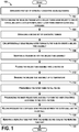
- Figure 1 is a flowchart that describes an example method 100 of manufacturing a double-walled tube by super plastically forming and diffusion bonding an outer wall, an inner wall and inner structures of the double-walled tube.
- the outer wall and the inner wall of the tube refer to interior and exterior layers of the tube, which comprises sheets concentrically wound together.
- the method 100 of super plastically forming and diffusion bonding may include one or more operations, functions, or actions as illustrated by one or more of blocks 102-118. Although the blocks are illustrated in a sequential order, these blocks may in some instances be performed in parallel, and/or in a different order than those described herein. Also, the various blocks may be combined into fewer blocks, divided into additional blocks, and/or removed based upon the desired implementation.
- the method 100 includes arranging a first set of intimately concentric seamless tubings.
- the concentric seamless tubings have approximately matching diameters to enable contact during a stitch welding process.
- the tubings can be sandwiched together in a circular manner by using a seamless tubing or rolled tubing.
- flat sheets of titanium may be arranged together and wound up to form the concentric titanium seamless tubes.
- the method 100 optionally includes cleaning the seamless tubings to remove oxidation.
- the method 100 includes stitch welding the seamless tubings with a rolled tubing seam welder to create a pack, including a stitch pattern, which later forms inner-to-outer wall stiffeners. Stitch welding the seamless tubings may create the stitch pattern along a length of the seamless tubings.
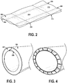
- Figure 2 illustrates a portion of seamless tubings with an example stitch pattern welded thereon.
- the portion includes tubings 202 and 204 arranging intimately together, and stitch welding has been performed.
- the stitch pattern in Figure 2 includes a number of parallel lines 206 and 208 run along a length of the tubings 202 and 204, and other parallel lines 210 and 212 run along a width of the tubings 202 and 204.
- the lines 206 and 208 are perpendicular to the lines 210 and 212.
- lines 206, 208, 210, and 212 are shown and described as running along a length and width of the tubings 202 and 204, stitch welding may be performed in other manners so as to weld stitches, or areas along the tubings 202 and 204 with spaces between the stitches, for example.
- the stitch pattern creates individual cells, such as cells 214 and 216 for example, that run a length of the material.
- a seam welder may be used to provide a weld pattern along a length of the tubing such as to provide the weld lines 206, 208, 210, and 212, and a different roll seam welder may be used to go around a diameter of the tubing for weld points to generate a desired cellular structure layout.
- the method 100 includes arranging a second set of concentric tubings, and at block 108, the method 100 includes circumferentially seam welding outer tubings to the pack to create a welded tube assembly. In one example, this includes placing the pack between a first outer tubing and a second outer tubing, and then circumferentially welding a perimeter of ends of the first outer tubing, the second outer tubing, and the pack (i.e., the stitch welded tubings). In one example, the pack may include the welded structure shown in Figure 2 , and two layers of material may be provided around the pack for welding.
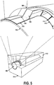
- Figure 3 illustrates a portion of an example welded tube assembly.
- a seam welder has been used to provide a perimeter weld 302 enclosing the inner two sheets that are stitch welded and shown in Figure 2 between two outer sheets 304 and 306.
- the perimeter weld may be a circumferential weld on the outer sheets at an end of the sheets.
- the portion of the welded tube assembly is tubular or a cylindrical shape.
- Figure 4 illustrates a portion of another example welded tube assembly.
- the welded tube assembly is shown to be more elliptical in shape.
- the tube assembly may be configured to have a cross-sectional shape of other circular or ellipsoid shapes are as well.
- the method 100 includes inserting a cylinder die into the welded tube assembly, and at block 112, the method 100 includes placing the welded tube assembly into a heated die.
- An example die is a three piece die to hold a shape on an inside of the tubing (e.g., cylinder die form) and two outer die halves.
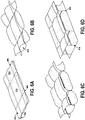
- Figure 5 illustrates an example tubing and an example die form.
- a cylinder die 502 is inserted into the tubing, which includes layers 504 and 506 of the tubing (in which layer 504 is an inner wall of the tubing), and a stitch welded pack 508 stitch welded together.
- the welded tube assembly is then inserted into a lower die 510 and an upper die 512.
- the three piece die including cylinder die 502, the lower die 510, and the upper die 512 is used to hold the shape of the tubing during a bonding process.
- Figure 5 shows a substantially linear length of tubing with substantially constant cross section, it will be readily understood that the curvature and cross section of the tubing may be non-linear and curved, or any other configuration.
- the method 100 includes bringing the welded tube assembly up to temperature.
- the welded tube assembly within the die is heated to a temperature in a range of about 788°C (1450° F) to about 1010°C (1850° F), or in a range of about 815°C (1500° F) to about 927°C (1700° F) degrees depending on an alloy of the materials.
- the method 100 includes pressurizing the outer tubes to fill the die, and at block 118, the method 100 includes pressurizing the inner welded tube assembly to form the inner structures according to the stitch pattern.
- a pressure may be applied at a pressure of about 2 MPa (300 psi), or other pressures to enable a diffusion bond process to occur.
- diffusion bonds may be created within the pack 508, such as diffusion bond 514. Diffusion bonds may also occur between the layers 504 and 506 and the pack 508, such as diffusion bond 516, 518, and 520.
- the pressurizing causes the layers 504 and 506 of the tubing to fill contours of the heated lower die 510 and upper die 512. Pressurizing also causes the pack 508 to form cells within the inner wall based on the stitch pattern. For example, the stitch pattern provides boundaries to enable the cells to expand. Heating and pressurizing allows the sheets to be bonded together.
- Figures 6A-6D illustrate examples of formation of cells within a stitch welded pack based on the stitch pattern.
- Figure 6A illustrates two sheets 602 and 604 stitch welded with stitches 606 and 608 to forms cells, such as cells 610 and 612.
- cells such as cells 610 and 612.
- Figure 6B shows an initial stage of bubbles forming, such as bubble 614.
- Figure 6C shows a subsequent stage with the bubbles more fully formed and expanding.
- Figure 6D shows an example final formation of the cells, which may be rectangles, squares, or any other shapes, and diffusion bonds have formed between the sheets, such as diffusion bonds 616 and 618.
- the method 100 includes holding pressure for a diffusion bond process between the outer wall and the inner wall.
- the pressure is held to enable the inner wall to diffusion bond to the outer wall.
- the pressure can be held for a time period, such as about three hours, to enable the outer wall and the inner wall to go through the diffusion bond process such that the outer wall and the inner wall become an integral piece.
- the pressure also enables full forming of the cells, or inner structures of the tubing, to form.
- the method 100 includes removing a resulting tube part from the heated die and cooling the resulting tube part.
- FIGs 7A-7F illustrate another view of examples of formation of cells within a tubular structure based on a stitch pattern.
- a welded pack assembly is shown including an inner wall 702, an outer wall 704, and a pack including stitch welded sheets with stitch welds, such as stitch welds 706.
- the inner wall and the outer wall are bonded to the stitch pack forming a weld 708 at the stitchings.
- FIG 7C further bonding takes place within the pack assembly and some cell formation occurs.
- additional bonding takes place within the pack assembly, and stitch welds continue to form cells.
- the stitch welds become stiffeners, and cell formation is complete.
- diffusion bonding occurs by holding at pressure resulting in diffusion bonds (e.g., bond 710).
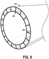
- Figure 8 illustrates an example resulting tube part.
- the tube may be a double-walled titanium tube structure that includes an inner wall 802 and an outer wall 804 with a plurality of stiffeners, such as stiffener 806, extending between the inner wall 802 to the outer wall 804.
- the plurality of stiffeners are aligned both axially and radially, and the plurality of stiffeners are diffusion bonded to the inner wall 802 and the outer wall 804.
- the double-walled titanium tube structure shown in Figure 8 may be a unitary tube with no fasteners resulting from multiple concentric tubes of titanium resistance welded prior to die forming at temperature and pressure.
- the plurality of stiffeners provide a continuous internal load path for the tube for greater strength.
- the annulus of the tube can be used for insulative purposes for corrosion resistant or heat resistant applications.
- the annulus with a specific stitch pattern can also accommodate a parallel or counter flow in any configuration of air or fluids.
- the method 100 shown in Figure 1 may be performed to manufacture a number or variety of types of double-walled conduits or tube structures.
- One example includes a seamless, open annulus, heated press process, as shown and described.
- Another example includes a seamless, closed annulus, heated press process following stitch welding, spot or circumferential welding can be performed for radial spacing.
- Yet another example includes a rolled tube, open annulus, heated press process, in which the sheets are rolled into tubing, and friction stir welded to ensure SPF properties.
- Still another example includes a rolled tube, closed annulus, heated press process in which both spot or circumferential welding and friction stir welding are performed.
- Figure 9 is a flowchart that describes another example method 900 of manufacturing a double-walled titanium conduit.
- the method 900 may include one or more operations, functions, or actions as illustrated by one or more of blocks 902-910. Although the blocks are illustrated in a sequential order, these blocks may in some instances be performed in parallel, and/or in a different order than those described herein. Also, the various blocks may be combined into fewer blocks, divided into additional blocks, and/or removed based upon the desired implementation.
- the method 900 includes stitch welding multiple concentric sheets to form a stitch layer.
- stitch welding creates a pattern on the multiple concentric sheets that form a size and shape of the inner structures.
- the inner structures can include at least one stiffener extending between outer sheets of an outer wall of the conduit.
- the method 900 includes providing the stitch layer between an inner wall and an outer wall of the double-walled titanium conduit.
- a specific stitch welding pattern may be chosen based on an application of the conduit for creation of a pathway or creation of cells between the inner wall and the outer wall.
- the method 900 includes circumferentially seam welding the inner wall and the outer wall to the stitch layer to create a welded assembly.
- the welded assembly is now in a tubular shape and configuration.
- the method 900 includes die forming the welded assembly at temperature and pressure to form inner structures between the multiple concentric sheets according to stitch welding lines and to enable a diffusion bond process among the inner wall, the stitch layer, and the outer wall.
- a shape and configuration of dies can be chosen based on an application of the conduit. Pressure and temperature are applied for the diffusion bonding process to occur such as at 300 psi and 1450° F for about 3 hours.
- the method 900 includes removing the double-walled titanium conduit from the die.
- the double-walled titanium conduit is a tubular structure.
- the double-walled titanium conduit is an ellipsoid structure.
- a titanium (or other alloy) double-walled tube can be manufactured that is corrosion resistant, heat resistant, and structurally reinforced with increased cross section for greater strength to provide a fail safety for a titanium tube.
- Example uses include tubing for transport elements or structural applications in extreme environments, such as oil industry or aerospace, for example.
Description
- The present disclosure relates generally to super plastically forming and diffusion bonding a titanium dual walled tubing, and more specifically to a double walled titanium tube that has an inner wall and an outer wall with at least one stiffener extending from the inner wall to the outer wall.
- Tubing and duct systems for conveying fluids are in widespread use in many industries. In the aerospace industry, for example, welded ducts are used in environmental control systems and in wing de-icing systems for conveying heated air from the engine to leading edges and nacelle inlet nose to prevent ice from forming on those surfaces in icing conditions in flight. Tubing, of course, may be utilized in many other industries as well including the oil industry or other industries in which transport elements are required for use in extreme environments at times.
- Tubing materials may be manufactured using superplastic forming (SPF) and diffusion bonding (DB) techniques. For many years it has been known that certain metals, such as titanium and many of its alloys, exhibit superplasticity. Superplasticity is the capability of a material to develop unusually high tensile elongations with reduced tendency toward necking. This capability is exhibited by a few metals and alloys and within a limited temperature and strain rate range. Titanium and titanium alloys have been observed to exhibit superplastic characteristics equal to or greater than those of any other metals. With suitable titanium alloys, overall increase in surface areas up to 300% are possible, for example. Advantages of superplastic forming are numerous including abilities to create complex shapes and deep drawn parts, and low deformation stresses are required to form the metal at the superplastic temperature range thereby permitting forming of parts under low pressures that minimize tool deformation and wear.
- Diffusion bonding (DB) refers to metallurgical joining of surfaces of similar or dissimilar metals by applying heat and pressure for a time duration so as to cause co-mingling of atoms at the joint interface. Diffusion bonding can be accomplished entirely in the solid-state at or above one-half the base metal melting point (absolute). Actual times, temperatures, and pressures will vary from metal to metal. The joining surfaces are brought within atomic distances by application of pressure. Adequate pressure is provided to cause some plastic flow to fill normal void areas. If pressures are too low, small voids may remain at the joint interface and the joint strength will be less than the maximum obtainable. The application of pressure also breaks up the surface oxides and surface asperities so as to present clean surfaces for bonding. Elevated temperatures used for diffusion bonding serve the functions of accelerating diffusion of atoms at the joint interfaces and providing a metal softening which aids in surface deformation so as to allow more intimate contact for atom bonding and movement across the joint interface. Elevated temperature and application of pressure also results in diffusion of the surface contaminants into the base metal during bonding which allows metal atom-to-atom bonding and thereby strengthens the bond. Sufficient time is allowed to ensure the strengthening of the bond by diffusion of atoms across the joint interface.
- According to existing processes, tubing sheets are manufactured in a flat form, in which one or more superplastically formable metal sheets are placed in a die cavity defined between cooperable dies, the sheets are heated to an elevated temperature at which the sheets exhibit superplasticity, and then a gas is used to apply differential pressures to the opposite sides of the sheets in order to form the sheets. The pressure is selected to strain the material at a strain rate that is within its superplasticity range at the elevated temperature, stretch the sheets, and cause the sheet to assume the shape of the die surface. In this way, the sheets can be formed to a complex shape defined by the dies.
- In other existing processes, SPF and DB can be performed in a combined forming/bonding operation. For instance, in one example combined SPF/DB process, three metal sheets are stacked in a flat form to form a pack. A stop-off material is selectively provided between the sheets to prevent portions of the adjacent surfaces of the sheets from being bonded. The pack is heated and compressed in a die cavity with sufficient gas pressure so that the adjacent portions of the sheets that are not treated with the stop-off material are joined by diffusion bonding. Thereafter, a pressurized gas is injected between the sheets to inflate the pack, and thereby superplastically form the pack to a configuration defined by the surface of the die cavity. Such a combined SPF/DB process can be used, e.g., to produce complex honeycomb sandwich structures that are formed and diffusion bonded to define hollow internal cells. Generally, the simplicity of the superplastic forming and/or diffusion bonding processes can result in lighter and less expensive structures with fewer fasteners and higher potential geometric complexity.
- However, using existing superplastic forming and diffusion bonding processes results in flat sheets that still require further manufacturing processes to form the sheets into a tubing system, which may alter the bonds created. Using examples described herein, a titanium (or other alloy) double-walled tube can be manufactured using SPF and DB that is corrosion resistant, heat resistant, and structurally reinforced with increased cross section for greater strength than seen in flat sheets to provide a fail safety for a titanium tube.
-
JP 2004 245115 -
ES 2 181 512 -
WO 2012/081927 in accordance with its abstract states a method for manufacturing an integrated cylinder using welding or diffusion welding. It further recites a method for manufacturing an integrated cylinder, in which four annular metal disks each having a diameter that enables the four annular metal disks to contact and be overlapped with each other, are partially welded or diffusion welded, placed within a tool, and blow-formed at a vacuum state, with the result that the two metal disks located in the middle are formed into a reinforcing portion and the outermost and innermost metal disks are formed into an inner surface and an outer surface of the cylinder. -
CN 103 008 997 in accordance with its abstract states a sheet-metal forming technology, and relates to a superplastic forming (SPF)/diffusion bonding (DB) forming method of a titanium alloy cylindrical three-layer structure. A novel blank structural form and a blank production method are adopted, the requirements on coating welding stopping agent and positioning a cylinder on a three-layer structure can be met, and a hot isostatic pressure DB and cylinder SPF step-by-step formation method is adopted for the cylinder blank, so that the technical difficulty and complexity can be reduced, and the structural flexibility can be improved. A partition ring is creatively additionally arranged among the cylinders, the dropping of the welding stopping agent, caused by the collision of the cylinders, can be avoided, an air inlet passage and an exhaust passage are directly machined and formed on the blank, no air passage needs to be machined on a mold, and the structural complexity of a tool can be reduced. The SPF/DB formation of the titanium alloy cylindrical three-layer structure can be stably and reliably realized, and the formation quality and the technological stability can be improved. The SPF/DB technological method is enlarged from the formation of a flat sandwich structure to the formation of the cylindrical rotation sandwich structure, so that the application field of the process can be enlarged, and good economic and technical benefit can be realized. - A first aspect of the present disclosure relates to a method of manufacturing a double-walled titanium conduit according to
claim 1. - In another example useful for understanding the present disclosure, another method of manufacturing a double-walled tube is described comprising super plastically forming inner structures of the double-walled tube, and diffusion bonding an outer wall, an inner wall and the inner structures of the double-walled tube. The super plastically forming and diffusion bonding comprises arranging substantially intimately concentric seamless tubings, stitch welding the seamless tubings with a rolled tubing seam welder to create a pack which later forms the inner-to-outer wall stiffeners including a stitch pattern, circumferentially seam welding concentric outer sheets of the outer wall to the inner wall and the stitched pack to create a welded tube assembly. The forming process also includes inserting a cylinder die into the welded tube assembly, placing the welded tube assembly into a heated die, bringing the welded tube assembly up to temperature, pressurizing the welded tube assembly to form the inner structures according to the stitch pattern, holding pressure for a diffusion bond process between the outer wall and the inner wall, and removing a resulting tube part from the heated die and cooling the resulting tube part.
- A second aspect of the disclosure relates to a double-walled titanium tube structure according to
claim 3. - Further details can be seen with reference to the following description and drawings.
- The novel features believed characteristic of the illustrative embodiments are set forth in the appended claims. The illustrative embodiments, however, as well as a preferred mode of use, further objectives and descriptions thereof, will best be understood by reference to the following detailed description of an illustrative embodiment of the present disclosure when read in conjunction with the accompanying drawings, wherein:
-
Figure 1 is a flowchart that describes an example method of manufacturing a double-walled tube by super plastically forming the diffusion bonding an outer wall, an inner wall and inner structures of the double-walled tube. -
Figure 2 illustrates a portion of seamless tubings with an example stitch pattern welded thereon. -
Figure 3 illustrates a portion of an example welded tube assembly. -
Figure 4 illustrates a portion of another example welded tube assembly.Figure 5 illustrates an example tubing and an example die form. -
Figures 6A-6D illustrate examples of formation of cells within the inner walls based on the stitch pattern. -
Figures 7A-7F illustrate another view of examples of formation of cells within a tubular structure based on a stitch pattern. -
Figure 8 illustrates an example resulting tube part. -
Figure 9 is a flowchart that describes another example method of manufacturing a double-walled titanium conduit. - Disclosed embodiments will now be described more fully hereinafter with reference to the accompanying drawings, in which some, but not all of the disclosed embodiments are shown. Indeed, several different embodiments may be described and should not be construed as limited to the embodiments set forth herein. Rather, these embodiments are described so that this disclosure will be thorough and complete and will fully convey the scope of the disclosure to those skilled in the art.
- Within examples, methods and systems for superplastic forming (SPF) and diffusion bonding a double-walled conduit are described. SPF generally refers to a process in which a material is superplastically deformed beyond its normal limits of plastic deformation. Superplastic forming can be performed with certain materials that exhibit superplastic properties within limited ranges of temperature and strain rate. For example, workpieces formed of titanium alloys can be superplastically formed in a temperature range between about 788°C (1450° F) and about 1010°C (1850° F) at a strain rate up to about 3×10⁻⁴ per second. Diffusion bonding (DB) generally refers to a process of joining members using heat and pressure to form a solid-state coalescence between the materials of the joined members. Joining by diffusion bonding can occur at a temperature below a melting point of the materials that are being joined, and the coalescence therebetween may be produced with loads below those that would cause macroscopic deformation of the article.
- In example, super plastically forming and diffusion bonding a titanium dual walled tubing can be achieved by manufacturing a double walled titanium tube that has an inner wall and an outer wall with at least one stiffener extending from the inner wall to the outer wall. The tubing may include a plurality of stiffeners aligned axially, and in other examples, the tubing may include a plurality of stiffeners aligned both axially and radially.
- An example method of super plastically forming and diffusion bonding the double walled titanium tube includes arranging substantially intimately concentric seamless tubings, cleaning the seamless tubings, and stitch welding the seamless tubings with a rolled tubing seam welder. Following, the method includes circumferentially seam welding outer tubing to inner tubing, including a stitch welded pack, fusion welding pressure lines, and inserting a cylinder die into the tube assembly. The tube assembly can be placed into a heated die and brought up to temperature and pressure that is held for a diffusion bond process to occur over a period of time. A resulting part can be removed from the die and cooled for use or further processing.
- Referring now to the figures,
Figure 1 is a flowchart that describes anexample method 100 of manufacturing a double-walled tube by super plastically forming and diffusion bonding an outer wall, an inner wall and inner structures of the double-walled tube. The outer wall and the inner wall of the tube refer to interior and exterior layers of the tube, which comprises sheets concentrically wound together. Themethod 100 of super plastically forming and diffusion bonding may include one or more operations, functions, or actions as illustrated by one or more of blocks 102-118. Although the blocks are illustrated in a sequential order, these blocks may in some instances be performed in parallel, and/or in a different order than those described herein. Also, the various blocks may be combined into fewer blocks, divided into additional blocks, and/or removed based upon the desired implementation. - At
block 102, themethod 100 includes arranging a first set of intimately concentric seamless tubings. In some examples, the concentric seamless tubings have approximately matching diameters to enable contact during a stitch welding process. The tubings can be sandwiched together in a circular manner by using a seamless tubing or rolled tubing. In one example, flat sheets of titanium may be arranged together and wound up to form the concentric titanium seamless tubes. - In some examples, the
method 100 optionally includes cleaning the seamless tubings to remove oxidation. - At
block 104, themethod 100 includes stitch welding the seamless tubings with a rolled tubing seam welder to create a pack, including a stitch pattern, which later forms inner-to-outer wall stiffeners. Stitch welding the seamless tubings may create the stitch pattern along a length of the seamless tubings. -
Figure 2 illustrates a portion of seamless tubings with an example stitch pattern welded thereon. InFigure 2 , the portion includestubings Figure 2 includes a number ofparallel lines tubings parallel lines tubings lines lines lines tubings tubings - The stitch pattern creates individual cells, such as
cells - Referring back to
Figure 1 , atblock 106, themethod 100 includes arranging a second set of concentric tubings, and atblock 108, themethod 100 includes circumferentially seam welding outer tubings to the pack to create a welded tube assembly. In one example, this includes placing the pack between a first outer tubing and a second outer tubing, and then circumferentially welding a perimeter of ends of the first outer tubing, the second outer tubing, and the pack (i.e., the stitch welded tubings). In one example, the pack may include the welded structure shown inFigure 2 , and two layers of material may be provided around the pack for welding. -
Figure 3 illustrates a portion of an example welded tube assembly. InFigure 3 , a seam welder has been used to provide aperimeter weld 302 enclosing the inner two sheets that are stitch welded and shown inFigure 2 between twoouter sheets Figure 3 , the portion of the welded tube assembly is tubular or a cylindrical shape. -
Figure 4 illustrates a portion of another example welded tube assembly. InFigure 4 , the welded tube assembly is shown to be more elliptical in shape. The tube assembly may be configured to have a cross-sectional shape of other circular or ellipsoid shapes are as well. - Referring back to
Figure 1 , atblock 110, themethod 100 includes inserting a cylinder die into the welded tube assembly, and atblock 112, themethod 100 includes placing the welded tube assembly into a heated die. An example die is a three piece die to hold a shape on an inside of the tubing (e.g., cylinder die form) and two outer die halves. -
Figure 5 illustrates an example tubing and an example die form. InFigure 5 , acylinder die 502 is inserted into the tubing, which includeslayers layer 504 is an inner wall of the tubing), and a stitch weldedpack 508 stitch welded together. The welded tube assembly is then inserted into alower die 510 and anupper die 512. The three piece die including cylinder die 502, thelower die 510, and theupper die 512 is used to hold the shape of the tubing during a bonding process. WhileFigure 5 shows a substantially linear length of tubing with substantially constant cross section, it will be readily understood that the curvature and cross section of the tubing may be non-linear and curved, or any other configuration. - Referring back to
Figure 1 , atblock 114, themethod 100 includes bringing the welded tube assembly up to temperature. As one example, the welded tube assembly within the die is heated to a temperature in a range of about 788°C (1450° F) to about 1010°C (1850° F), or in a range of about 815°C (1500° F) to about 927°C (1700° F) degrees depending on an alloy of the materials. - At
block 116, themethod 100 includes pressurizing the outer tubes to fill the die, and atblock 118, themethod 100 includes pressurizing the inner welded tube assembly to form the inner structures according to the stitch pattern. A pressure may be applied at a pressure of about 2 MPa (300 psi), or other pressures to enable a diffusion bond process to occur. As an example, as shown inFigure 5 , diffusion bonds may be created within thepack 508, such asdiffusion bond 514. Diffusion bonds may also occur between thelayers pack 508, such asdiffusion bond - The pressurizing causes the
layers upper die 512. Pressurizing also causes thepack 508 to form cells within the inner wall based on the stitch pattern. For example, the stitch pattern provides boundaries to enable the cells to expand. Heating and pressurizing allows the sheets to be bonded together. -
Figures 6A-6D illustrate examples of formation of cells within a stitch welded pack based on the stitch pattern.Figure 6A illustrates twosheets stitches cells sheets Figure 6B shows an initial stage of bubbles forming, such asbubble 614.Figure 6C shows a subsequent stage with the bubbles more fully formed and expanding.Figure 6D shows an example final formation of the cells, which may be rectangles, squares, or any other shapes, and diffusion bonds have formed between the sheets, such asdiffusion bonds - Referring back to
Figure 1 , atblock 120, themethod 100 includes holding pressure for a diffusion bond process between the outer wall and the inner wall. The pressure is held to enable the inner wall to diffusion bond to the outer wall. The pressure can be held for a time period, such as about three hours, to enable the outer wall and the inner wall to go through the diffusion bond process such that the outer wall and the inner wall become an integral piece. The pressure also enables full forming of the cells, or inner structures of the tubing, to form. - At
block 122, themethod 100 includes removing a resulting tube part from the heated die and cooling the resulting tube part. -
Figures 7A-7F illustrate another view of examples of formation of cells within a tubular structure based on a stitch pattern. InFigure 7A , a welded pack assembly is shown including aninner wall 702, anouter wall 704, and a pack including stitch welded sheets with stitch welds, such as stitch welds 706. InFigure 7B , the inner wall and the outer wall are bonded to the stitch pack forming aweld 708 at the stitchings. InFigure 7C , further bonding takes place within the pack assembly and some cell formation occurs. InFigure 7D , again, additional bonding takes place within the pack assembly, and stitch welds continue to form cells. InFigure 7E , the stitch welds become stiffeners, and cell formation is complete. InFigure 7F , diffusion bonding occurs by holding at pressure resulting in diffusion bonds (e.g., bond 710). -
Figure 8 illustrates an example resulting tube part. As shown, the tube may be a double-walled titanium tube structure that includes aninner wall 802 and anouter wall 804 with a plurality of stiffeners, such asstiffener 806, extending between theinner wall 802 to theouter wall 804. The plurality of stiffeners are aligned both axially and radially, and the plurality of stiffeners are diffusion bonded to theinner wall 802 and theouter wall 804. - The double-walled titanium tube structure shown in
Figure 8 may be a unitary tube with no fasteners resulting from multiple concentric tubes of titanium resistance welded prior to die forming at temperature and pressure. The plurality of stiffeners provide a continuous internal load path for the tube for greater strength. The annulus of the tube can be used for insulative purposes for corrosion resistant or heat resistant applications. The annulus with a specific stitch pattern can also accommodate a parallel or counter flow in any configuration of air or fluids. - The
method 100 shown inFigure 1 may be performed to manufacture a number or variety of types of double-walled conduits or tube structures. One example includes a seamless, open annulus, heated press process, as shown and described. Another example includes a seamless, closed annulus, heated press process following stitch welding, spot or circumferential welding can be performed for radial spacing. Yet another example includes a rolled tube, open annulus, heated press process, in which the sheets are rolled into tubing, and friction stir welded to ensure SPF properties. Still another example includes a rolled tube, closed annulus, heated press process in which both spot or circumferential welding and friction stir welding are performed. -
Figure 9 is a flowchart that describes anotherexample method 900 of manufacturing a double-walled titanium conduit. Themethod 900 may include one or more operations, functions, or actions as illustrated by one or more of blocks 902-910. Although the blocks are illustrated in a sequential order, these blocks may in some instances be performed in parallel, and/or in a different order than those described herein. Also, the various blocks may be combined into fewer blocks, divided into additional blocks, and/or removed based upon the desired implementation. - At
block 902, themethod 900 includes stitch welding multiple concentric sheets to form a stitch layer. In some examples, stitch welding creates a pattern on the multiple concentric sheets that form a size and shape of the inner structures. The inner structures can include at least one stiffener extending between outer sheets of an outer wall of the conduit. - At
block 904, themethod 900 includes providing the stitch layer between an inner wall and an outer wall of the double-walled titanium conduit. A specific stitch welding pattern may be chosen based on an application of the conduit for creation of a pathway or creation of cells between the inner wall and the outer wall. - At
block 906, themethod 900 includes circumferentially seam welding the inner wall and the outer wall to the stitch layer to create a welded assembly. The welded assembly is now in a tubular shape and configuration. - At
block 908, themethod 900 includes die forming the welded assembly at temperature and pressure to form inner structures between the multiple concentric sheets according to stitch welding lines and to enable a diffusion bond process among the inner wall, the stitch layer, and the outer wall. A shape and configuration of dies can be chosen based on an application of the conduit. Pressure and temperature are applied for the diffusion bonding process to occur such as at 300 psi and 1450° F for about 3 hours. - At
block 910, themethod 900 includes removing the double-walled titanium conduit from the die. Within examples, the double-walled titanium conduit is a tubular structure. In other examples, the double-walled titanium conduit is an ellipsoid structure. - Using examples described herein, a titanium (or other alloy) double-walled tube can be manufactured that is corrosion resistant, heat resistant, and structurally reinforced with increased cross section for greater strength to provide a fail safety for a titanium tube. Example uses include tubing for transport elements or structural applications in extreme environments, such as oil industry or aerospace, for example.
- The description of the different advantageous arrangements has been presented for purposes of illustration and description, and is not intended to be exhaustive or limited to the embodiments in the form disclosed. Many modifications and variations will be apparent to those of ordinary skill in the art. Further, different advantageous embodiments may describe different advantages as compared to other advantageous embodiments. The embodiment or embodiments selected are chosen and described in order to best explain the principles of the embodiments, the practical application, and to enable others of ordinary skill in the art to understand the disclosure for various embodiments with various modifications as are suited to the particular use contemplated.
Claims (6)
- A method of manufacturing a double-walled titanium conduit, comprising:stitch welding a set of intimately concentric seamless tubings to form a stitch layer (902), the stitch welding forming a pattern including a number of first lines (206, 208) which run parallel along a length of the tubings and a number of second lines (210, 212) which run perpendicular to the first lines along a width of the tubings;providing the stitch layer (902) between an inner wall tubing (702, 802) and an outer wall tubing (704, 804) of the double-walled titanium conduit (904) such that the tubings are arranged concentrically;seam welding respective ends of the inner wall tubing (702, 802) and the outer wall tubing (704, 804) to the stitch layer (902) around the respective circumferences of the tubings to create a welded assembly (906);die forming the welded assembly at temperature and pressure to form inner structures (610, 612) between the inner wall tubing and the outer wall tubing according to the stitch welding lines and to enable a diffusion bond process among the inner wall tubing (702, 802), the stitch layer (902), and the outer wall tubing (704, 804) (908); and removing the double-walled titanium conduit from the die (910).
- The method of claim 1, wherein stitch welding is applied to create a pattern on the intimately concentric seamless tubings (602, 604) that form a size and shape of the inner structures (610, 612).
- A double-walled titanium tube structure manufactured according to the method of one of the claims 1 or 2, comprising:an inner wall (702, 802) and an outer wall (704, 804) with a first plurality of stiffeners (806) extending between the inner wall (702, 802) to the outer wall (704, 804) and a second plurality of stiffeners extending between the inner wall (702, 802) to the outer wall (704, 804); andwherein the first plurality of stiffeners (806) are aligned both axially and radially, and the second plurality of stiffeners are aligned both perpendicular to the first plurality of stiffeners and radially, and the first and second plurality of stiffeners (806) are diffusion bonded to the inner wall (702, 802) and the outer wall (704, 804).
- The double-walled titanium tube structure of claim 3, wherein the inner wall (702, 802) and the outer wall (704, 804) comprise a unitary tube with no fasteners.
- The double-walled titanium tube structure of claims 3 or 4, wherein the plurality of stiffeners (806) provide a continuous internal load path.
- The double-walled titanium tube structure of claims 3, 4 or 5, wherein the inner wall (702, 802) and the outer wall (802, 804) are diffusion bonded.
Priority Applications (1)
| Application Number | Priority Date | Filing Date | Title |
|---|---|---|---|
| EP20160569.8A EP3680038A1 (en) | 2015-02-11 | 2016-02-02 | Dual walled titanium tubing and method of manufacturing the tubing |
Applications Claiming Priority (1)
| Application Number | Priority Date | Filing Date | Title |
|---|---|---|---|
| US14/619,449 US9446483B2 (en) | 2015-02-11 | 2015-02-11 | Dual walled titanium tubing and methods of manufacturing the tubing |
Related Child Applications (2)
| Application Number | Title | Priority Date | Filing Date |
|---|---|---|---|
| EP20160569.8A Division EP3680038A1 (en) | 2015-02-11 | 2016-02-02 | Dual walled titanium tubing and method of manufacturing the tubing |
| EP20160569.8A Division-Into EP3680038A1 (en) | 2015-02-11 | 2016-02-02 | Dual walled titanium tubing and method of manufacturing the tubing |
Publications (2)
| Publication Number | Publication Date |
|---|---|
| EP3056292A1 EP3056292A1 (en) | 2016-08-17 |
| EP3056292B1 true EP3056292B1 (en) | 2021-11-17 |
Family
ID=55275029
Family Applications (2)
| Application Number | Title | Priority Date | Filing Date |
|---|---|---|---|
| EP16153777.4A Active EP3056292B1 (en) | 2015-02-11 | 2016-02-02 | Dual walled titanium tubing and methods of manufacturing the tubing |
| EP20160569.8A Pending EP3680038A1 (en) | 2015-02-11 | 2016-02-02 | Dual walled titanium tubing and method of manufacturing the tubing |
Family Applications After (1)
| Application Number | Title | Priority Date | Filing Date |
|---|---|---|---|
| EP20160569.8A Pending EP3680038A1 (en) | 2015-02-11 | 2016-02-02 | Dual walled titanium tubing and method of manufacturing the tubing |
Country Status (7)
| Country | Link |
|---|---|
| US (2) | US9446483B2 (en) |
| EP (2) | EP3056292B1 (en) |
| JP (2) | JP6868336B2 (en) |
| CN (1) | CN105855318B (en) |
| BR (2) | BR102016000227B1 (en) |
| CA (3) | CA2920623C (en) |
| ES (1) | ES2905434T3 (en) |
Families Citing this family (6)
| Publication number | Priority date | Publication date | Assignee | Title |
|---|---|---|---|---|
| US9446483B2 (en) * | 2015-02-11 | 2016-09-20 | The Boeing Company | Dual walled titanium tubing and methods of manufacturing the tubing |
| US11260952B2 (en) | 2019-09-26 | 2022-03-01 | The Boeing Company | Reinforced superplastic formed and diffusion bonded structures |
| CN111604645A (en) * | 2020-05-23 | 2020-09-01 | 北京普惠三航科技有限公司 | Forming method of air inlet pipe of aircraft engine |
| US20220388090A1 (en) * | 2021-06-04 | 2022-12-08 | The Boeing Company | Fabrication of thick stock via diffusion bonding of titanium alloys |
| DE102021116727A1 (en) * | 2021-06-29 | 2022-12-29 | Linde + Wiemann SE & Co. KG | Process for the production of a profile component from a tubular metallic semi-finished product |
| CN116944681B (en) * | 2023-09-19 | 2023-11-21 | 迪森(常州)能源装备有限公司 | Automatic pressure-resistant welding device and method for circumferential seams of pressure containers |
Citations (1)
| Publication number | Priority date | Publication date | Assignee | Title |
|---|---|---|---|---|
| CN103008997A (en) * | 2012-12-14 | 2013-04-03 | 中国航空工业集团公司北京航空制造工程研究所 | Superplastic forming (SPF)/diffusion bonding (DB) forming method of titanium alloy cylindrical four-layer structure |
Family Cites Families (38)
| Publication number | Priority date | Publication date | Assignee | Title |
|---|---|---|---|---|
| US4043498A (en) * | 1974-02-11 | 1977-08-23 | Tre Corporation | Method of plastic flow diffusion bonding |
| US3927817A (en) | 1974-10-03 | 1975-12-23 | Rockwell International Corp | Method for making metallic sandwich structures |
| US4217397A (en) * | 1978-04-18 | 1980-08-12 | Mcdonnell Douglas Corporation | Metallic sandwich structure and method of fabrication |
| US4304821A (en) * | 1978-04-18 | 1981-12-08 | Mcdonnell Douglas Corporation | Method of fabricating metallic sandwich structure |
| GB2030480B (en) * | 1978-09-29 | 1982-08-04 | British Aerospace | Method of making a stiffened panel |
| IT1150849B (en) * | 1982-04-20 | 1986-12-17 | Snam Progetti | THERMALLY INSULATED PIPING FOR THE CONSTRUCTION OF UNDERWATER PIPES |
| US4833768A (en) * | 1988-04-28 | 1989-05-30 | Mcdonnell Douglas Corporation | Curved SPF/DB sandwich fabrication |
| GB8821222D0 (en) * | 1988-09-09 | 1988-12-14 | British Aerospace | Double curvature structures by superplastic forming & diffusion bonding |
| US5410132A (en) | 1991-10-15 | 1995-04-25 | The Boeing Company | Superplastic forming using induction heating |
| US5645744A (en) | 1991-04-05 | 1997-07-08 | The Boeing Company | Retort for achieving thermal uniformity in induction processing of organic matrix composites or metals |
| US5641422A (en) | 1991-04-05 | 1997-06-24 | The Boeing Company | Thermoplastic welding of organic resin composites using a fixed coil induction heater |
| US5728309A (en) | 1991-04-05 | 1998-03-17 | The Boeing Company | Method for achieving thermal uniformity in induction processing of organic matrix composites or metals |
| US5683608A (en) | 1991-04-05 | 1997-11-04 | The Boeing Company | Ceramic die for induction heating work cells |
| US5420400A (en) | 1991-10-15 | 1995-05-30 | The Boeing Company | Combined inductive heating cycle for sequential forming the brazing |
| US5229562A (en) | 1991-04-05 | 1993-07-20 | The Boeing Company | Process for consolidation of composite materials |
| US5599472A (en) | 1991-04-05 | 1997-02-04 | The Boeing Company | Resealable retort for induction processing of organic matrix composites or metals |
| US5141146A (en) * | 1991-06-06 | 1992-08-25 | Mcdonnell Douglas Corporation | Fabrication of superplastically formed trusscore structure |
| US5330092A (en) * | 1991-12-17 | 1994-07-19 | The Boeing Company | Multiple density sandwich structures and method of fabrication |
| US5214948A (en) | 1991-12-18 | 1993-06-01 | The Boeing Company | Forming metal parts using superplastic metal alloys and axial compression |
| US5687900A (en) * | 1995-03-28 | 1997-11-18 | Mcdonnell Douglas Corporation | Structural panel having a predetermined shape and an associated method for superplastically forming and diffusion bonding the structural panel |
| DE69636148T2 (en) * | 1996-01-12 | 2007-03-01 | The Boeing Co., Chicago | Sandwich structures with several sheets and an integrated hardpoint |
| US6430812B1 (en) | 1997-08-28 | 2002-08-13 | The Boeing Company | Superplastic forming of tubing pull-outs |
| US6138898A (en) * | 1998-12-22 | 2000-10-31 | The Boeing Company | Corner gap weld pattern for SPF core packs |
| ES2181512B1 (en) | 1999-06-15 | 2004-05-16 | Mecanizaciones Aeronauticas, S.A. | MANUFACTURING PROCEDURE FOR THREE-DIMENSIONAL ELEMENTS IN METAL MATERIALS. |
| US6855917B2 (en) | 2001-12-06 | 2005-02-15 | The Boeing Company | Induction processable ceramic die with durable die liner |
| US6528771B1 (en) | 2002-03-08 | 2003-03-04 | The Boeing Company | System and method for controlling an induction heating process |
| US6566635B1 (en) | 2002-03-08 | 2003-05-20 | The Boeing Company | Smart susceptor having a geometrically complex molding surface |
| JP2004245115A (en) | 2003-02-13 | 2004-09-02 | Mitsubishi Heavy Ind Ltd | Manufacturing method of cooling passage structure, manufacturing method of nozzle having cooling passage, and nozzle having cooling passage |
| US6914225B2 (en) | 2003-06-18 | 2005-07-05 | The Boeing Company | Apparatus and methods for single sheet forming using induction heating |
| US7533794B2 (en) | 2004-03-31 | 2009-05-19 | The Boring Company | Superplastic forming and diffusion bonding of fine grain titanium |
| US6897419B1 (en) | 2004-04-02 | 2005-05-24 | The Boeing Company | Susceptor connection system and associated apparatus and method |
| FR2879715B1 (en) * | 2004-12-17 | 2007-04-06 | Saipem S A Sa | SUB-MARINE COAXIAL CONDUIT ELEMENT ALLEGE AND REINFORCED |
| US8884201B2 (en) | 2008-09-15 | 2014-11-11 | The Boeing Company | Systems and methods for fabrication of thermoplastic components |
| KR20120068369A (en) | 2010-12-17 | 2012-06-27 | 한국항공우주연구원 | Manufacturing method of an integrated cylinder |
| US9820339B2 (en) | 2011-09-29 | 2017-11-14 | The Boeing Company | Induction heating using induction coils in series-parallel circuits |
| US8963058B2 (en) | 2011-11-28 | 2015-02-24 | The Boeing Company | System and method of adjusting the equilibrium temperature of an inductively-heated susceptor |
| CN103008998B (en) | 2012-12-14 | 2015-05-27 | 中国航空工业集团公司北京航空制造工程研究所 | Superplastic forming (SPF)/diffusion bonding (DB) forming method of titanium alloy cylindrical three-layer structure |
| US9446483B2 (en) | 2015-02-11 | 2016-09-20 | The Boeing Company | Dual walled titanium tubing and methods of manufacturing the tubing |
-
2015
- 2015-02-11 US US14/619,449 patent/US9446483B2/en active Active
-
2016
- 2016-01-04 CN CN201610001314.2A patent/CN105855318B/en active Active
- 2016-01-06 BR BR102016000227-3A patent/BR102016000227B1/en active IP Right Grant
- 2016-01-06 BR BR122021021125A patent/BR122021021125B8/en active IP Right Grant
- 2016-02-02 EP EP16153777.4A patent/EP3056292B1/en active Active
- 2016-02-02 EP EP20160569.8A patent/EP3680038A1/en active Pending
- 2016-02-02 ES ES16153777T patent/ES2905434T3/en active Active
- 2016-02-10 CA CA2920623A patent/CA2920623C/en active Active
- 2016-02-10 CA CA3107784A patent/CA3107784C/en active Active
- 2016-02-10 CA CA3189459A patent/CA3189459A1/en active Pending
- 2016-02-10 JP JP2016023358A patent/JP6868336B2/en active Active
- 2016-07-21 US US15/215,916 patent/US9810348B2/en active Active
-
2021
- 2021-01-29 JP JP2021012708A patent/JP7134271B2/en active Active
Patent Citations (1)
| Publication number | Priority date | Publication date | Assignee | Title |
|---|---|---|---|---|
| CN103008997A (en) * | 2012-12-14 | 2013-04-03 | 中国航空工业集团公司北京航空制造工程研究所 | Superplastic forming (SPF)/diffusion bonding (DB) forming method of titanium alloy cylindrical four-layer structure |
Also Published As
| Publication number | Publication date |
|---|---|
| EP3056292A1 (en) | 2016-08-17 |
| CA2920623A1 (en) | 2016-08-11 |
| US20160327188A1 (en) | 2016-11-10 |
| BR122021021125B8 (en) | 2024-02-27 |
| US20160228997A1 (en) | 2016-08-11 |
| JP6868336B2 (en) | 2021-05-12 |
| CN105855318B (en) | 2020-08-28 |
| CA3107784C (en) | 2023-04-04 |
| CA2920623C (en) | 2021-03-23 |
| BR102016000227A2 (en) | 2016-10-18 |
| CA3189459A1 (en) | 2016-08-11 |
| US9446483B2 (en) | 2016-09-20 |
| EP3680038A1 (en) | 2020-07-15 |
| BR122021021125B1 (en) | 2023-06-27 |
| US9810348B2 (en) | 2017-11-07 |
| JP2021098229A (en) | 2021-07-01 |
| ES2905434T3 (en) | 2022-04-08 |
| JP7134271B2 (en) | 2022-09-09 |
| CN105855318A (en) | 2016-08-17 |
| CA3107784A1 (en) | 2016-08-11 |
| JP2016185566A (en) | 2016-10-27 |
| BR102016000227B1 (en) | 2022-07-05 |
Similar Documents
| Publication | Publication Date | Title |
|---|---|---|
| EP3056292B1 (en) | Dual walled titanium tubing and methods of manufacturing the tubing | |
| US9527571B2 (en) | Superplastically formed ultrasonically welded metallic structure | |
| CN100364685C (en) | Production of clad pipes | |
| Kleiner et al. | Metal forming techniques for lightweight construction | |
| US7048175B2 (en) | Friction welded structural assembly and preform and method for same | |
| JP5235672B2 (en) | Titanium assembly superplastic forming method and structure of aircraft manufactured thereby | |
| US5687900A (en) | Structural panel having a predetermined shape and an associated method for superplastically forming and diffusion bonding the structural panel | |
| US7416105B2 (en) | Superplastically forming of friction welded structural assemblies | |
| JPH038523A (en) | Making of cellular structure and cellular structure | |
| US6571450B2 (en) | Process for the monolithic molding of superplastic material | |
| JPH03505304A (en) | Superplastic forming/diffusion bonded sandwich curved structure | |
| EP1034063B1 (en) | A method for producing rotational-symmetrical articles of sheet metal with double curved surface and varying thickness of material | |
| US11052445B2 (en) | Hydroforming of porthole extrusion with non-equiangular seams | |
| JPH11169977A (en) | Integral formation of superplastic metals | |
| US6338189B1 (en) | Method and apparatus for expansion forming a workpiece using an external deformable supporting fixture | |
| US10118259B1 (en) | Corrosion resistant bimetallic tube manufactured by a two-step process | |
| JPS6061167A (en) | Production of metallic bellows | |
| RU2268102C1 (en) | Laminate structure manufacturing method |
Legal Events
| Date | Code | Title | Description |
|---|---|---|---|
| PUAI | Public reference made under article 153(3) epc to a published international application that has entered the european phase |
Free format text: ORIGINAL CODE: 0009012 |
|
| AK | Designated contracting states |
Kind code of ref document: A1 Designated state(s): AL AT BE BG CH CY CZ DE DK EE ES FI FR GB GR HR HU IE IS IT LI LT LU LV MC MK MT NL NO PL PT RO RS SE SI SK SM TR |
|
| AX | Request for extension of the european patent |
Extension state: BA ME |
|
| STAA | Information on the status of an ep patent application or granted ep patent |
Free format text: STATUS: REQUEST FOR EXAMINATION WAS MADE |
|
| 17P | Request for examination filed |
Effective date: 20170208 |
|
| RBV | Designated contracting states (corrected) |
Designated state(s): AL AT BE BG CH CY CZ DE DK EE ES FI FR GB GR HR HU IE IS IT LI LT LU LV MC MK MT NL NO PL PT RO RS SE SI SK SM TR |
|
| STAA | Information on the status of an ep patent application or granted ep patent |
Free format text: STATUS: EXAMINATION IS IN PROGRESS |
|
| 17Q | First examination report despatched |
Effective date: 20181023 |
|
| GRAP | Despatch of communication of intention to grant a patent |
Free format text: ORIGINAL CODE: EPIDOSNIGR1 |
|
| STAA | Information on the status of an ep patent application or granted ep patent |
Free format text: STATUS: GRANT OF PATENT IS INTENDED |
|
| INTG | Intention to grant announced |
Effective date: 20191022 |
|
| GRAJ | Information related to disapproval of communication of intention to grant by the applicant or resumption of examination proceedings by the epo deleted |
Free format text: ORIGINAL CODE: EPIDOSDIGR1 |
|
| STAA | Information on the status of an ep patent application or granted ep patent |
Free format text: STATUS: EXAMINATION IS IN PROGRESS |
|
| INTC | Intention to grant announced (deleted) | ||
| STAA | Information on the status of an ep patent application or granted ep patent |
Free format text: STATUS: EXAMINATION IS IN PROGRESS |
|
| GRAP | Despatch of communication of intention to grant a patent |
Free format text: ORIGINAL CODE: EPIDOSNIGR1 |
|
| STAA | Information on the status of an ep patent application or granted ep patent |
Free format text: STATUS: GRANT OF PATENT IS INTENDED |
|
| INTG | Intention to grant announced |
Effective date: 20210416 |
|
| GRAJ | Information related to disapproval of communication of intention to grant by the applicant or resumption of examination proceedings by the epo deleted |
Free format text: ORIGINAL CODE: EPIDOSDIGR1 |
|
| STAA | Information on the status of an ep patent application or granted ep patent |
Free format text: STATUS: EXAMINATION IS IN PROGRESS |
|
| GRAP | Despatch of communication of intention to grant a patent |
Free format text: ORIGINAL CODE: EPIDOSNIGR1 |
|
| STAA | Information on the status of an ep patent application or granted ep patent |
Free format text: STATUS: GRANT OF PATENT IS INTENDED |
|
| INTC | Intention to grant announced (deleted) | ||
| INTG | Intention to grant announced |
Effective date: 20210618 |
|
| GRAS | Grant fee paid |
Free format text: ORIGINAL CODE: EPIDOSNIGR3 |
|
| GRAA | (expected) grant |
Free format text: ORIGINAL CODE: 0009210 |
|
| STAA | Information on the status of an ep patent application or granted ep patent |
Free format text: STATUS: THE PATENT HAS BEEN GRANTED |
|
| AK | Designated contracting states |
Kind code of ref document: B1 Designated state(s): AL AT BE BG CH CY CZ DE DK EE ES FI FR GB GR HR HU IE IS IT LI LT LU LV MC MK MT NL NO PL PT RO RS SE SI SK SM TR |
|
| REG | Reference to a national code |
Ref country code: GB Ref legal event code: FG4D |
|
| REG | Reference to a national code |
Ref country code: DE Ref legal event code: R096 Ref document number: 602016066229 Country of ref document: DE |
|
| REG | Reference to a national code |
Ref country code: IE Ref legal event code: FG4D |
|
| REG | Reference to a national code |
Ref country code: AT Ref legal event code: REF Ref document number: 1447632 Country of ref document: AT Kind code of ref document: T Effective date: 20211215 |
|
| REG | Reference to a national code |
Ref country code: LT Ref legal event code: MG9D |
|
| REG | Reference to a national code |
Ref country code: NL Ref legal event code: MP Effective date: 20211117 |
|
| REG | Reference to a national code |
Ref country code: ES Ref legal event code: FG2A Ref document number: 2905434 Country of ref document: ES Kind code of ref document: T3 Effective date: 20220408 |
|
| REG | Reference to a national code |
Ref country code: AT Ref legal event code: MK05 Ref document number: 1447632 Country of ref document: AT Kind code of ref document: T Effective date: 20211117 |
|
| PG25 | Lapsed in a contracting state [announced via postgrant information from national office to epo] |
Ref country code: RS Free format text: LAPSE BECAUSE OF FAILURE TO SUBMIT A TRANSLATION OF THE DESCRIPTION OR TO PAY THE FEE WITHIN THE PRESCRIBED TIME-LIMIT Effective date: 20211117 Ref country code: LT Free format text: LAPSE BECAUSE OF FAILURE TO SUBMIT A TRANSLATION OF THE DESCRIPTION OR TO PAY THE FEE WITHIN THE PRESCRIBED TIME-LIMIT Effective date: 20211117 Ref country code: FI Free format text: LAPSE BECAUSE OF FAILURE TO SUBMIT A TRANSLATION OF THE DESCRIPTION OR TO PAY THE FEE WITHIN THE PRESCRIBED TIME-LIMIT Effective date: 20211117 Ref country code: BG Free format text: LAPSE BECAUSE OF FAILURE TO SUBMIT A TRANSLATION OF THE DESCRIPTION OR TO PAY THE FEE WITHIN THE PRESCRIBED TIME-LIMIT Effective date: 20220217 Ref country code: AT Free format text: LAPSE BECAUSE OF FAILURE TO SUBMIT A TRANSLATION OF THE DESCRIPTION OR TO PAY THE FEE WITHIN THE PRESCRIBED TIME-LIMIT Effective date: 20211117 |
|
| PG25 | Lapsed in a contracting state [announced via postgrant information from national office to epo] |
Ref country code: IS Free format text: LAPSE BECAUSE OF FAILURE TO SUBMIT A TRANSLATION OF THE DESCRIPTION OR TO PAY THE FEE WITHIN THE PRESCRIBED TIME-LIMIT Effective date: 20220317 Ref country code: SE Free format text: LAPSE BECAUSE OF FAILURE TO SUBMIT A TRANSLATION OF THE DESCRIPTION OR TO PAY THE FEE WITHIN THE PRESCRIBED TIME-LIMIT Effective date: 20211117 Ref country code: PT Free format text: LAPSE BECAUSE OF FAILURE TO SUBMIT A TRANSLATION OF THE DESCRIPTION OR TO PAY THE FEE WITHIN THE PRESCRIBED TIME-LIMIT Effective date: 20220317 Ref country code: PL Free format text: LAPSE BECAUSE OF FAILURE TO SUBMIT A TRANSLATION OF THE DESCRIPTION OR TO PAY THE FEE WITHIN THE PRESCRIBED TIME-LIMIT Effective date: 20211117 Ref country code: NO Free format text: LAPSE BECAUSE OF FAILURE TO SUBMIT A TRANSLATION OF THE DESCRIPTION OR TO PAY THE FEE WITHIN THE PRESCRIBED TIME-LIMIT Effective date: 20220217 Ref country code: NL Free format text: LAPSE BECAUSE OF FAILURE TO SUBMIT A TRANSLATION OF THE DESCRIPTION OR TO PAY THE FEE WITHIN THE PRESCRIBED TIME-LIMIT Effective date: 20211117 Ref country code: LV Free format text: LAPSE BECAUSE OF FAILURE TO SUBMIT A TRANSLATION OF THE DESCRIPTION OR TO PAY THE FEE WITHIN THE PRESCRIBED TIME-LIMIT Effective date: 20211117 Ref country code: HR Free format text: LAPSE BECAUSE OF FAILURE TO SUBMIT A TRANSLATION OF THE DESCRIPTION OR TO PAY THE FEE WITHIN THE PRESCRIBED TIME-LIMIT Effective date: 20211117 Ref country code: GR Free format text: LAPSE BECAUSE OF FAILURE TO SUBMIT A TRANSLATION OF THE DESCRIPTION OR TO PAY THE FEE WITHIN THE PRESCRIBED TIME-LIMIT Effective date: 20220218 |
|
| PG25 | Lapsed in a contracting state [announced via postgrant information from national office to epo] |
Ref country code: SM Free format text: LAPSE BECAUSE OF FAILURE TO SUBMIT A TRANSLATION OF THE DESCRIPTION OR TO PAY THE FEE WITHIN THE PRESCRIBED TIME-LIMIT Effective date: 20211117 Ref country code: SK Free format text: LAPSE BECAUSE OF FAILURE TO SUBMIT A TRANSLATION OF THE DESCRIPTION OR TO PAY THE FEE WITHIN THE PRESCRIBED TIME-LIMIT Effective date: 20211117 Ref country code: RO Free format text: LAPSE BECAUSE OF FAILURE TO SUBMIT A TRANSLATION OF THE DESCRIPTION OR TO PAY THE FEE WITHIN THE PRESCRIBED TIME-LIMIT Effective date: 20211117 Ref country code: EE Free format text: LAPSE BECAUSE OF FAILURE TO SUBMIT A TRANSLATION OF THE DESCRIPTION OR TO PAY THE FEE WITHIN THE PRESCRIBED TIME-LIMIT Effective date: 20211117 Ref country code: DK Free format text: LAPSE BECAUSE OF FAILURE TO SUBMIT A TRANSLATION OF THE DESCRIPTION OR TO PAY THE FEE WITHIN THE PRESCRIBED TIME-LIMIT Effective date: 20211117 Ref country code: CZ Free format text: LAPSE BECAUSE OF FAILURE TO SUBMIT A TRANSLATION OF THE DESCRIPTION OR TO PAY THE FEE WITHIN THE PRESCRIBED TIME-LIMIT Effective date: 20211117 |
|
| REG | Reference to a national code |
Ref country code: DE Ref legal event code: R097 Ref document number: 602016066229 Country of ref document: DE |
|
| PLBE | No opposition filed within time limit |
Free format text: ORIGINAL CODE: 0009261 |
|
| STAA | Information on the status of an ep patent application or granted ep patent |
Free format text: STATUS: NO OPPOSITION FILED WITHIN TIME LIMIT |
|
| PG25 | Lapsed in a contracting state [announced via postgrant information from national office to epo] |
Ref country code: MC Free format text: LAPSE BECAUSE OF FAILURE TO SUBMIT A TRANSLATION OF THE DESCRIPTION OR TO PAY THE FEE WITHIN THE PRESCRIBED TIME-LIMIT Effective date: 20211117 |
|
| REG | Reference to a national code |
Ref country code: CH Ref legal event code: PL |
|
| REG | Reference to a national code |
Ref country code: BE Ref legal event code: MM Effective date: 20220228 |
|
| 26N | No opposition filed |
Effective date: 20220818 |
|
| PG25 | Lapsed in a contracting state [announced via postgrant information from national office to epo] |
Ref country code: AL Free format text: LAPSE BECAUSE OF FAILURE TO SUBMIT A TRANSLATION OF THE DESCRIPTION OR TO PAY THE FEE WITHIN THE PRESCRIBED TIME-LIMIT Effective date: 20211117 Ref country code: LU Free format text: LAPSE BECAUSE OF NON-PAYMENT OF DUE FEES Effective date: 20220202 |
|
| PG25 | Lapsed in a contracting state [announced via postgrant information from national office to epo] |
Ref country code: SI Free format text: LAPSE BECAUSE OF FAILURE TO SUBMIT A TRANSLATION OF THE DESCRIPTION OR TO PAY THE FEE WITHIN THE PRESCRIBED TIME-LIMIT Effective date: 20211117 |
|
| PG25 | Lapsed in a contracting state [announced via postgrant information from national office to epo] |
Ref country code: LI Free format text: LAPSE BECAUSE OF NON-PAYMENT OF DUE FEES Effective date: 20220228 Ref country code: IE Free format text: LAPSE BECAUSE OF NON-PAYMENT OF DUE FEES Effective date: 20220202 Ref country code: CH Free format text: LAPSE BECAUSE OF NON-PAYMENT OF DUE FEES Effective date: 20220228 |
|
| REG | Reference to a national code |
Ref country code: FR Ref legal event code: PLFP Year of fee payment: 8 |
|
| PG25 | Lapsed in a contracting state [announced via postgrant information from national office to epo] |
Ref country code: BE Free format text: LAPSE BECAUSE OF NON-PAYMENT OF DUE FEES Effective date: 20220228 |
|
| PGFP | Annual fee paid to national office [announced via postgrant information from national office to epo] |
Ref country code: FR Payment date: 20230223 Year of fee payment: 8 Ref country code: ES Payment date: 20230301 Year of fee payment: 8 |
|
| PGFP | Annual fee paid to national office [announced via postgrant information from national office to epo] |
Ref country code: IT Payment date: 20230221 Year of fee payment: 8 Ref country code: GB Payment date: 20230227 Year of fee payment: 8 Ref country code: DE Payment date: 20230223 Year of fee payment: 8 |
|
| P01 | Opt-out of the competence of the unified patent court (upc) registered |
Effective date: 20230516 |
|
| PG25 | Lapsed in a contracting state [announced via postgrant information from national office to epo] |
Ref country code: HU Free format text: LAPSE BECAUSE OF FAILURE TO SUBMIT A TRANSLATION OF THE DESCRIPTION OR TO PAY THE FEE WITHIN THE PRESCRIBED TIME-LIMIT; INVALID AB INITIO Effective date: 20160202 |