EP3056104A1 - Shoe sole - Google Patents
Shoe sole Download PDFInfo
- Publication number
- EP3056104A1 EP3056104A1 EP13895346.8A EP13895346A EP3056104A1 EP 3056104 A1 EP3056104 A1 EP 3056104A1 EP 13895346 A EP13895346 A EP 13895346A EP 3056104 A1 EP3056104 A1 EP 3056104A1
- Authority
- EP
- European Patent Office
- Prior art keywords
- cleats
- outsole
- shoe sole
- base
- midsole
- Prior art date
- Legal status (The legal status is an assumption and is not a legal conclusion. Google has not performed a legal analysis and makes no representation as to the accuracy of the status listed.)
- Granted
Links
Images


Classifications
-
- A—HUMAN NECESSITIES
- A43—FOOTWEAR
- A43B—CHARACTERISTIC FEATURES OF FOOTWEAR; PARTS OF FOOTWEAR
- A43B13/00—Soles; Sole-and-heel integral units
- A43B13/14—Soles; Sole-and-heel integral units characterised by the constructive form
- A43B13/22—Soles made slip-preventing or wear-resisting, e.g. by impregnation or spreading a wear-resisting layer
- A43B13/223—Profiled soles
-
- A—HUMAN NECESSITIES
- A43—FOOTWEAR
- A43B—CHARACTERISTIC FEATURES OF FOOTWEAR; PARTS OF FOOTWEAR
- A43B13/00—Soles; Sole-and-heel integral units
- A43B13/02—Soles; Sole-and-heel integral units characterised by the material
- A43B13/04—Plastics, rubber or vulcanised fibre
-
- A—HUMAN NECESSITIES
- A43—FOOTWEAR
- A43B—CHARACTERISTIC FEATURES OF FOOTWEAR; PARTS OF FOOTWEAR
- A43B13/00—Soles; Sole-and-heel integral units
- A43B13/02—Soles; Sole-and-heel integral units characterised by the material
- A43B13/12—Soles with several layers of different materials
-
- A—HUMAN NECESSITIES
- A43—FOOTWEAR
- A43B—CHARACTERISTIC FEATURES OF FOOTWEAR; PARTS OF FOOTWEAR
- A43B13/00—Soles; Sole-and-heel integral units
- A43B13/02—Soles; Sole-and-heel integral units characterised by the material
- A43B13/12—Soles with several layers of different materials
- A43B13/125—Soles with several layers of different materials characterised by the midsole or middle layer
-
- A—HUMAN NECESSITIES
- A43—FOOTWEAR
- A43B—CHARACTERISTIC FEATURES OF FOOTWEAR; PARTS OF FOOTWEAR
- A43B13/00—Soles; Sole-and-heel integral units
- A43B13/14—Soles; Sole-and-heel integral units characterised by the constructive form
- A43B13/141—Soles; Sole-and-heel integral units characterised by the constructive form with a part of the sole being flexible, e.g. permitting articulation or torsion
-
- A—HUMAN NECESSITIES
- A43—FOOTWEAR
- A43B—CHARACTERISTIC FEATURES OF FOOTWEAR; PARTS OF FOOTWEAR
- A43B13/00—Soles; Sole-and-heel integral units
- A43B13/14—Soles; Sole-and-heel integral units characterised by the constructive form
- A43B13/18—Resilient soles
- A43B13/181—Resiliency achieved by the structure of the sole
-
- A—HUMAN NECESSITIES
- A43—FOOTWEAR
- A43B—CHARACTERISTIC FEATURES OF FOOTWEAR; PARTS OF FOOTWEAR
- A43B13/00—Soles; Sole-and-heel integral units
- A43B13/14—Soles; Sole-and-heel integral units characterised by the constructive form
- A43B13/18—Resilient soles
- A43B13/187—Resiliency achieved by the features of the material, e.g. foam, non liquid materials
-
- A—HUMAN NECESSITIES
- A43—FOOTWEAR
- A43B—CHARACTERISTIC FEATURES OF FOOTWEAR; PARTS OF FOOTWEAR
- A43B13/00—Soles; Sole-and-heel integral units
- A43B13/14—Soles; Sole-and-heel integral units characterised by the constructive form
- A43B13/22—Soles made slip-preventing or wear-resisting, e.g. by impregnation or spreading a wear-resisting layer
- A43B13/24—Soles made slip-preventing or wear-resisting, e.g. by impregnation or spreading a wear-resisting layer by use of insertions
- A43B13/26—Soles made slip-preventing or wear-resisting, e.g. by impregnation or spreading a wear-resisting layer by use of insertions projecting beyond the sole surface
-
- A—HUMAN NECESSITIES
- A43—FOOTWEAR
- A43B—CHARACTERISTIC FEATURES OF FOOTWEAR; PARTS OF FOOTWEAR
- A43B5/00—Footwear for sporting purposes
- A43B5/02—Football boots or shoes, i.e. for soccer, football or rugby
-
- A—HUMAN NECESSITIES
- A43—FOOTWEAR
- A43B—CHARACTERISTIC FEATURES OF FOOTWEAR; PARTS OF FOOTWEAR
- A43B5/00—Footwear for sporting purposes
- A43B5/06—Running shoes; Track shoes
-
- A—HUMAN NECESSITIES
- A43—FOOTWEAR
- A43C—FASTENINGS OR ATTACHMENTS OF FOOTWEAR; LACES IN GENERAL
- A43C15/00—Non-skid devices or attachments
- A43C15/16—Studs or cleats for football or like boots
-
- A—HUMAN NECESSITIES
- A43—FOOTWEAR
- A43C—FASTENINGS OR ATTACHMENTS OF FOOTWEAR; LACES IN GENERAL
- A43C15/00—Non-skid devices or attachments
- A43C15/16—Studs or cleats for football or like boots
- A43C15/168—Studs or cleats for football or like boots with resilient means, e.g. shock absorbing means
Definitions
- the present invention relates to an improvement to the layered structure of a midsole and an outsole.
- a shoe sole is generally required to be light-weight, durable, gripping, shock-absorbing, bendable, etc., and each of these properties needs to be on a certain level or better while some of them are in a tradeoff relationship.
- one solution to increasing the gripping force of cleats is to increase the height of the cleats of the outsole.
- increasing the height of the cleats directly leads to an increase in the thickness of the cleats, which increases the weight.
- upthrust is likely to be felt from cleat areas.
- JP07-265103A discloses a shoe sole in which the interface between the midsole and the outsole is in a wave-like configuration as seen in a lateral cross section.
- a rubber-made outsole is formed with a uniform thickness. Therefore, there will likely be durability problems due to the outsole wearing out.
- JP05-65201Y discloses an injection-molded boot having cleats of a synthetic resin, which forms the body of the boot, protruding from the bottom surface of the shoe sole. Such a structure may not be suitable for a shoe sole including a midsole of a foam body and an outsole of a rubber.
- JP04-38701Y discloses a multilayer shoe sole in which a long groove extending in the width direction is formed in the forefoot portion of the lower shoe sole. With this shoe sole, it will be possible to realize a good bendability in the forefoot portion.
- JP2005-185303A discloses a stud that is thick in the bottom portion and thin in the upper portion.
- the stud of this prior art is not a rubber but is a resin spike material and has a lower hardness (D hardness) than that of the base. Therefore, the thick setting will not improve, but will rather lower, the grip of the stud.
- the high-hardness base shown in FIG.6 of the prior art is thin in its lower portion and thick in its upper portion. Therefore, the flexibility and the grip will be higher when the stud is solid (intact).
- An object of the present invention is to provide a shoe sole that can be expected to suppress the durability lowering and to be light-weight, gripping and shock-absorbing, as well as being adequately bendable. Moreover, one can also expect that it accommodates a greater design variety while taking environmental considerations.
- a shoe sole of the present invention includes:
- the concave surface 1F is formed on the upper surface 11 of the first cleats 1C of the outsole 1, thereby reducing the weight of the outsole 1, of which the specific gravity is much larger than that of the midsole 2.
- the concave surface 1F is formed on the upper surface of the first cleats 1C, with the convex portion 2P of the flexible midsole 2 fitted in the concave surface 1F. Therefore, the first cleats 1C will easily deform as compared with a case where the first cleats 1C are solid (intact). Thus, one can expect an improvement to the gripping property and the shock-absorbing property of the first cleats 1C.
- the distance 1D from the tread surface 10 of the first cleats 1C to the convex surface 2F of the midsole 2, i.e., the thickness of the tread (grounding) portion of the first cleats 1C, is generally greater than the thickness of the base 1B. Therefore, the durability of the sole will unlikely deteriorate due to the first cleats 1C wearing out.
- the outsole 1 made of a rubber is formed by a foamed rubber material (a rubber foam) having a relatively small expansion ratio or a non-foamed rubber material (a non-foam body of rubber), and the outsole 1 has a greater specific gravity than the midsole 2 but is superior in wear resistance.
- a foamed rubber material a rubber foam
- a non-foamed rubber material a non-foam body of rubber
- the foam body of the midsole 2 includes a thermoplastic resin component and any other suitable component.
- the thermoplastic resin component may include a thermoplastic elastomer and a thermoplastic resin.
- thermoplastic elastomer may include a styrene-based elastomer such as styrene-ethylene-butylene-styrene block copolymer (SEBS), and an ethylene-vinyl acetate copolymer (-based) elastomer.
- SEBS styrene-ethylene-butylene-styrene block copolymer
- -based ethylene-vinyl acetate copolymer
- thermoplastic resin may include a vinyl acetate-based resin such as ethylene-vinyl acetate copolymer (EVA), polystyrene, and a styrene-butadiene resin.
- EVA ethylene-vinyl acetate copolymer
- polystyrene polystyrene
- styrene-butadiene resin a vinyl acetate-based resin such as ethylene-vinyl acetate copolymer (EVA), polystyrene, and a styrene-butadiene resin.
- EVA ethylene-vinyl acetate copolymer
- polystyrene polystyrene
- styrene-butadiene resin styrene-butadiene resin
- a main (primary) component being a foam body means that a half or more of the upper surface 21 or the lower surface 20 of the midsole 2, or a half or more of the volume of the midsole 2, is formed by a foam body and that the midsole 2 may partially include gel, pod-like members (pods), or the like.
- the thickness of a member should be measured in the direction normal to the surface of the member.
- the Japanese word “top” means “top” in English, and it means the lower end of the convex surface 2F.
- the distance 1D from the tread surface 10 to the top 2T being greater than the thickness of the base 1B means that a cleat 1C may include a portion where the thickness is smaller than the thickness of the base 1B, and it is deemed (interpreted) that the relationship: distance 1D > base 1B is satisfied if at least any one or more of the requirements (1) to (8) below is satisfied or if any two or more of them are satisfied.
- tread surface 10 refers to the surface to be in contact with the ground when the sole is placed on a flat ground surface. Therefore, if a cleat includes a depressed (concave) portion at the center thereof, such a depressed portion does not form the tread surface 10.
- the mid sole 2 across the convex surface 2F is thicker than the base 2B around the convex portion 2P.
- the flexible midsole 2 is partially inside the first cleats 1C. Therefore, an upthrust is unlikely to be felt from the cleats 1C.
- the plurality of first cleats 1C each have a peripheral (outer circumferential) surface 1R extending between the tread surface 10 and the base 1B ; and a thickness of the outsole 1 along the peripheral surface 1R decreases as the outsole extends in an upward direction, and increases as the outsole extends in the downward direction.
- the upper portion of a first cleat 1C is thinner than the lower portion of the first cleat 1C.
- the first cleat 1C will likely undergo a shear deformation, which is approximate to a flexural deformation, about the upper end thereof joined with the midsole 2. Then, the largest moment occurs on the thin upper portion, and one can therefore expect that this will increase the deformation of the first cleat 1C.
- the lower portion of the first cleats 1C is more likely to come into contact with a hard object or the ground surface, than is the upper portion thereof.
- the lower portion of the first cleat 1C which is relatively thicker than the upper portion thereof, can suppress the deterioration of the durability of the first cleats 1C due to such contact.
- the first cleats 1C each have an upper edge portion 1E diagonally extending from the base 1B toward the tread surface 10 and being joined with a peripheral edge of the convex surface 2F ; and a thickness of the upper edge portion 1E is less than a thickness of the base 1B.
- the aforementioned deformation will occur about the upper edge portion 1E , which is thinner than the thickness of the base 1B. Therefore, the largest moment occurs on the thin upper edge portion 1E , and one can expect that this will further increase the deformation of the first cleat 1C.
- the first cleats 1C are arranged on (along) a medial edge 1M and/or a lateral edge 1L of the shoe sole, with a side surface of the convex portion 2P being exposed on the medial edge 1M and/or the lateral edge 1L.
- the convex portion 2P of the midsole 2 is exposed on the medial edge 1M and/or the lateral edge 1L, and the medial edge 1M and/or the lateral edge 1L, where the convex portion 2P of the midsole 2 is exposed, will more easily undergo (show) such a deformation as described above, as compared with a shoe sole with no such exposure.
- a plurality of the first cleats 1C are arranged intermittently along a medial edge 1M or a lateral edge 1L of the shoe sole, with a side surface of the convex portion 2P being exposed on the medial edge 1M or the lateral edge 1L ; and an interface between the upper surface 11 of the outsole 1 and the lower surface 20 of the midsole 2 appears (is displayed) as a wave-shaped (waveform) curve along the medial edge 1M or the lateral edge 1L.
- the first cleats 1C which are arranged intermittently, can easily undergo such a deformation as described above, and one can easily expect the advantageous effect from the deformation.
- a plurality of the first cleats 1C are arranged intermittently along a medial edge 1M of the shoe sole, with a side surface of the convex portion 2P being exposed on the medial edge 1M ; an interface between the upper surface 11 of the outsole 1 and the lower surface 20 of the midsole 2 appears (is displayed) as a wave-shaped (waveform) curve along the medial edge 1M ; a plurality of the first cleats 1C are arranged intermittently along a lateral edge 1L of the shoe sole, with a side surface of the convex portion 2P being exposed on the lateral edge 1L ; an interface between the upper surface 11 of the outsole 1 and the lower surface 20 of the midsole 2 appears as a wave-shaped (waveform) curve along the lateral edge 1L ; the plurality of first cleats 1C each have a peripheral (outer circumferential) surface 1R extending between the tread surface 10 and the base 1B ; and a thickness of the outsole 1 along
- the first cleats 1C which easily deform, are arranged intermittently both on the medial edge 1M and on the lateral edge 1L, and one can better expect the advantageous effect from the aforementioned deformation.
- the upper surface 21 of the midsole sinks in the downward direction generally along the longitudinal axis of the foot, thereby producing a guidance line while running, and one can expect an improvement to the stability while running.
- US-2011-0185590-A1 , WO101038266A1 e.g., US-2011-0185590-A1 , WO101038266A1
- a plurality of cleats 1C are arranged intermittently both on the medial edge 1M and on the lateral edge 1L. Therefore, the medial edge 1M and the lateral edge 1L will deform (shift, or be displaced) above other positions along the longitudinal axis of the foot while running, and the upper surface 21 of the midsole 2 will sink along the longitudinal axis of the foot. This may improve the stability of running.
- the outsole 1 includes three or more of the first cleats 1C or a plurality of second cleats other than (separate from) the first cleats 1C, with a first through hole H1 being defined in an area surrounded by three or more of the first and/or second cleats; and the mid sole 2 includes a further (another) first cleat 2C made of the foam body protruding (projecting out) in the downward direction Z through the first through hole H1.
- a runner runs on a hard ground surface covered with many pebbles or on a slope.
- the cleats may not easily bite into the hard ground surface, and the many pebbles may not easily bite into between the cleats.
- the first cleats 2C which are made of the foam body (foamed material) of the midsole 2, are much softer than the first cleats 1C of the outsole 1, and pebbles may easily bite into the midsole 2 on the hard ground surface.
- the first through holes H1 formed in the outsole 1 are helpful in reducing the weight of the outsole 1.
- the midsole 2 and the outsole 1 are joined (integrated) together, by being bonded or welded together, thereby increasing the thickness, thus significantly increasing the rigidity against flexure, i.e., the flexural rigidity EIz.
- the flexural rigidity EIz is in proportion to the Young's modulus of the material. Therefore, the first cleats 2C of the midsole 2 and the first through holes H1 formed in the outsole 1 contribute to the lowering of the flexural rigidity EIz, which will improve the bendability of the shoe sole.
- the first through holes H1 are provided in the outsole 1, of which the specific gravity is much larger than that of the midsole 2, it is possible to reduce the weight and it is also more desirable for the environment.
- the surface of the midsole 2 typically has a different color from the outsole 1 and/or a beautiful texture (appearance), and the cleats 2C of the midsole 2 and the outsole 1 forming a contrast in color therebetween will be helpful in increasing the design variety of the shoe sole.
- the base 1B of the outsole 1 has a plurality of through holes H2 defined in a central area 5A of a rear foot portion 5R; and the mid sole 2 includes a plurality of further (other) second cleats 20C made of the foam body and protruding (projecting out) in the downward direction Z through the second through holes H2.
- the second through holes H2 and the cleats 20C will realize similar effects to the first through hole H1 and the cleats 10C.
- a plurality of second through holes H2 and cleats 20C are provided in the central area 5A of the rear foot portion 5R, which will give the rear foot portion 5R a gripping property, and give the heel of the rear foot portion 5R an adequate cushioning property.
- the outsole 1 includes three or more of the first cleats 1C or a plurality of second cleats other than (separate from) the first cleats 1C, with a first through hole H1 being defined in an area surrounded by three or more of the first and/or second cleats;
- the midsole 2 includes a plurality of further (other) first cleats 2C made of the foam body and protruding (projecting out) in the downward direction Z through the first through hole H1;
- the base 1B of the outsole 1 has a plurality of second through holes H2 defined in a central area 5A of a rear foot portion 5R;
- the midsole 2 includes a plurality of further (other) second cleats 20C made of the foam body and protruding (projecting out) in the downward direction Z through the second through holes H2; and a total number of first and second cleats 2C and 20C of the midsole 2 is set to be 6 to 40.
- the 6 to 40 first and second cleats 2C and 20C of the midsole 2 will provide novel designs of a shoe sole.
- the number of first and second cleats 2C and 20C of the midsole 2 is preferably 8 to 35, and most preferably about 10 to 30.
- a Young's modulus of the outsole 1 is greater than a Young's modulus of the midsole 2.
- the hardness of a foamed resin material (foam body of resin) or that of a rubber has a strong correlation with the Young's modulus.
- the midsole 2 is typically more flexible than the outsole 1, and the hardness thereof is much smaller than that of the outsole 1. However, because their hardnesses are measured by using different methods, the concept of Young's modulus is employed instead of their hardness relationship.
- the hardness of the midsole 2 is set to about 40° to 75° in terms of the asker C hardness.
- the hardness of the outsole 1 is set to about 55° to 70° in terms of the JIS-A hardness. Note that 70° in the JIS-A hardness corresponds to about 86° in the asker C hardness.
- the present embodiment is a shoe sole of a shoe for trail running, for example.
- the shoe sole includes one outsole 1 made of a rubber, and one midsole 2 made of a resin. Note that an upper (not shown) wrapping around the instep is provided on the shoe sole.
- a primary component of the midsole 2 is a foam body of EVA, for example, and the midsole 2 may include a reinforcement unit 29.
- the midsole 2 may be provided with a low-resilience material, a high-resilience material, a groove, etc.
- the outsole 1 is a tread bottom having a greater wear resistance than the foam body of the midsole 2, and typically has a greater hardness and a greater Young's modulus than those of the foam body of the midsole 2.
- "made of a rubber” herein means that it contains a component of a natural rubber or a synthetic rubber, and may contain any other suitable component.
- the outsole 1 includes the tread surface 10 and the upper surface 11.
- the midsole 2 includes the upper surface 21 and the lower surface 20, and the lower surface 20 is attached to the upper surface 11 of the outsole 1.
- the midsole 2 of FIG. 1 generally covers the entire surface of the foot sole.
- the outsole 1 of FIG. 2 includes a base portion 1B, and many first cleats 1C and many first and second through holes H1 and H2 formed on the base portion 1B.
- the lower surface 20 of the midsole 2 protrudes through some of the through holes H1 and H2, thereby forming many first and second cleats 2C and 20C.
- first and second cleats 2C and 20C of the midsole 2 are shaded with dots in FIG. 1 to FIG. 3 .
- the outsole 1 of FIG. 2 includes a plate-like base 1B and many first cleats 1C.
- the plurality of first cleats 1C protrude downward in the downward direction Z from the base 1B to form the tread surface 10, wherein the plurality of first cleats 1C are arranged in the longitudinal direction and in the transverse direction.
- the upper surface 11 of each of the first cleats 1C includes the concave surface 1F recessed in the downward direction Z.
- the lower surface 20 of the midsole 2 of FIG. 1 includes the convex surface 2F formed by the surface of the convex portion 2P protruding in the downward direction Z from the base 2B of the midsole 2.
- the concave surface 1F and the convex surface 2F are in contact with each other and are attached (joined by being bonded or welded) together.
- the distance 1D from the tread surface 10 to the top 2T of the convex surface 2F in each of the first cleats 1C is greater than the thickness Tb of the base 1B. For example, the distance 1D shown in FIG.
- the first cleats 1C and the base 1B of the present embodiment satisfy one or more of the requirements (1) to (8) defined above.
- the midsole 2 at the convex surface 2F is thicker than the base 2B around the convex portion 2P.
- the lower surface 20 of the generally flat base 2B of the midsole 2 is joined, by being bonded or welded, with the upper surface 11 of the generally flat base 1B of the outsole 1.
- line L1 in FIG. 3 and FIG. 5A to FIG. 5E denotes a reference line.
- the plurality of first cleats 1C of FIG. 5B each have the peripheral surface 1R extending between the tread surface 10 and the base 1B.
- the thickness of the outsole 1 along the peripheral surface 1R decreases in the upward direction and increases in the downward direction.
- the peripheral surface 1R has the upper edge portion 1E diagonally extending downward from the base 1B toward the tread surface 10 and being joined with a peripheral edge of the convex surface 2F, and the thickness Tr of the upper edge portion 1E is slightly smaller than the thickness Tb of the base 1B.
- many (not all) of the first cleats 1C are arranged intermittently along the medial edge 1M and the lateral edge 1L of the shoe sole, with the side surface of the convex portion 2P being exposed on the medial edge 1M and the lateral edge 1L. Note that in FIG. 4A and FIG. 4B , the side surface of the midsole 2 is shaded with dots.
- the medial and lateral edges 1M and 1L are flexible, and is easily bendable as indicated by an arrow in FIG. 5D so that the central portion on the medial side and on the lateral side of the midsole 2 can easily sink in the downward direction.
- the plurality of first cleats 1C along the side edges 1M and 1L each have the peripheral surface 1R extending between the tread surface 10 and the base 1B, and the thickness of the outsole 1 along the peripheral surface 1R decreases in the upward direction and increases in the downward direction as shown in FIG. 5B, FIG. 5C and FIG. 5E .
- each first through hole H1 is formed in a portion of the base portion 1B surrounded by three or four of the first cleats 1C of the outsole 1.
- Each first cleat 2C of the midsole 2 protrudes in the downward direction Z through the first through hole H1.
- the outsole 1 may include normal, second cleats, different from the cleats 1C, e.g., cleats with no concave surface 1F, and the first through holes H1 and the first cleats 2C of the midsole 2 may be provided each in an area of the base 1B surrounded by three or four of the second cleats or the first cleats 1C.
- the base 1B of the outsole 1 is formed in a lattice pattern with a few (three) or more through holes H2 formed therein. These second through holes H2 are provided adjacent to each other in the central area 5A of the rear foot portion 5R of the base 1B of the outsole 1.
- Each second cleat 20C of the midsole 2 protrudes in the downward direction Z through a corresponding one of the second through holes H2.
- the hard first cleats 1C of the outsole 1 are arranged around (i.e., on the front side, the rear side, the medial side M and the lateral side of) the group of second cleats 20C. These first cleats 1C are useful in protecting the group of second cleats 20C.
- the central area 5A of the rear foot portion 5R means an area of the rear foot portion 5R excluding the front and rear ends and the medial and lateral edges 1M and 1L of the rear foot portion 5R.
- the total number of first and second cleats 2C and 20C of the midsole 2 is set to be 10 to 20, for example.
- the top 2T of the first and second cleats 2C and 20C made of the foam body shown in FIG. 1 and FIG. 5D is spaced further away from the ground surface than the tread surface 10 of the first cleats 1C of the outsole 1. Therefore, it will unlikely come into contact with the ground on a flat ground surface, while it will likely come into contact with the ground on a hard ground surface with many pebbles thereon.
- a small through hole may be provided running through a cleat 1C with the convex surface 2F of the midsole 2 being exposed through the through hole.
- the cleats 2C and the cleats 20C may not be protruding through the first through holes H1 and the second through holes H2 of the midsole 2 of FIG. 2 , and the flat lower surface 20 of the base 2B of the midsole 2 may instead be exposed through the first through holes H1, etc.
- the reinforcement unit 29 may be absent (not be provided). Grooves may be provided around cleats of the outsole.
- the midsole and/or the outsole may each be formed by a plurality of layers of member.
- the present invention is applicable to the shoe sole of walking shoes, rain shoes and shoes of daily use, as well as to the shoe sole of athletic shoes, such as trail running shoes, mountain climbing shoes and cross country shoes.
Landscapes
- Chemical & Material Sciences (AREA)
- Engineering & Computer Science (AREA)
- Materials Engineering (AREA)
- Health & Medical Sciences (AREA)
- General Health & Medical Sciences (AREA)
- Physical Education & Sports Medicine (AREA)
- Footwear And Its Accessory, Manufacturing Method And Apparatuses (AREA)
Abstract
Description
- The present invention relates to an improvement to the layered structure of a midsole and an outsole.
- A shoe sole is generally required to be light-weight, durable, gripping, shock-absorbing, bendable, etc., and each of these properties needs to be on a certain level or better while some of them are in a tradeoff relationship. In recent years, there has been a demand for better designing the tread surface of a shoe sole and for taking environmental considerations with a shoe sole.
- For example, with a trail running shoe, or the like, one solution to increasing the gripping force of cleats is to increase the height of the cleats of the outsole. However, increasing the height of the cleats directly leads to an increase in the thickness of the cleats, which increases the weight. Moreover, with high cleats, upthrust is likely to be felt from cleat areas.
-
- First Patent Document:
JP07-265103A - Second Patent Document:
JP05-65201Y - Third Patent Document:
JP04-38701Y - Fourth Patent Document:
JP2005-185303A -
JP07-265103A -
JP05-65201Y -
JP04-38701Y -
JP2005-185303A - That is, the high-hardness base shown in FIG.6 of the prior art is thin in its lower portion and thick in its upper portion. Therefore, the flexibility and the grip will be higher when the stud is solid (intact).
- An object of the present invention is to provide a shoe sole that can be expected to suppress the durability lowering and to be light-weight, gripping and shock-absorbing, as well as being adequately bendable. Moreover, one can also expect that it accommodates a greater design variety while taking environmental considerations.
- A shoe sole of the present invention includes:
- an
outsole 1 made of a rubber having atread surface 10 and anupper surface 11; and - a
mid sole 2 having anupper surface 21 and alower surface 20, wherein thelower surface 20 is attached to theupper surface 11 of theoutsole 1, and a main (primary) component of themid sole 2 is a foam body (foamed material) having a thermoplastic resin component, wherein:- the
outsole 1 includes:- a
base 1B; - a plurality of
first cleats 1C protruding in a downward direction Z from thebase 1B to form thetread surface 10, wherein the plurality offirst cleats 1C are arranged not only in a longitudinal direction, but also in a transverse direction; and - a concave (depressed)
surface 1F recessed (concaved) in the downward direction Z on theupper surface 11 of each of thefirst cleats 1C; - the
lower surface 20 of themid sole 2 includes a convex (protruding)surface 2F formed by a surface of a convex (protruding)portion 2P protruding (projecting out) in the downward direction Z from abase 2B of themid sole 2; - the
concave surface 1F and theconvex surface 2F are in contact with, and attached to, each other; and - a
distance 1D from thetread surface 10 to a top 2T of theconvex surface 2F in each of thefirst cleats 1C is greater than a thickness of thebase 1B.
- a
- the
- According to the present invention, the
concave surface 1F is formed on theupper surface 11 of thefirst cleats 1C of theoutsole 1, thereby reducing the weight of theoutsole 1, of which the specific gravity is much larger than that of themidsole 2. - The
concave surface 1F is formed on the upper surface of thefirst cleats 1C, with theconvex portion 2P of theflexible midsole 2 fitted in theconcave surface 1F. Therefore, thefirst cleats 1C will easily deform as compared with a case where thefirst cleats 1C are solid (intact). Thus, one can expect an improvement to the gripping property and the shock-absorbing property of thefirst cleats 1C. - On the other hand, since the
distance 1D from thetread surface 10 of thefirst cleats 1C to theconvex surface 2F of themidsole 2, i.e., the thickness of the tread (grounding) portion of thefirst cleats 1C, is generally greater than the thickness of thebase 1B. Therefore, the durability of the sole will unlikely deteriorate due to thefirst cleats 1C wearing out. - Herein, the
outsole 1 made of a rubber is formed by a foamed rubber material (a rubber foam) having a relatively small expansion ratio or a non-foamed rubber material (a non-foam body of rubber), and theoutsole 1 has a greater specific gravity than themidsole 2 but is superior in wear resistance. - The foam body of the
midsole 2 includes a thermoplastic resin component and any other suitable component. Examples of the thermoplastic resin component may include a thermoplastic elastomer and a thermoplastic resin. - Example types of the thermoplastic elastomer may include a styrene-based elastomer such as styrene-ethylene-butylene-styrene block copolymer (SEBS), and an ethylene-vinyl acetate copolymer (-based) elastomer.
- Example types of the thermoplastic resin may include a vinyl acetate-based resin such as ethylene-vinyl acetate copolymer (EVA), polystyrene, and a styrene-butadiene resin. The resin components listed above may be used alone or in combination of two or more.
- As used in the present invention, "a main (primary) component being a foam body" means that a half or more of the
upper surface 21 or thelower surface 20 of themidsole 2, or a half or more of the volume of themidsole 2, is formed by a foam body and that themidsole 2 may partially include gel, pod-like members (pods), or the like. - Note that the thickness of a member should be measured in the direction normal to the surface of the member.
- As used in the present invention, the Japanese word "top" means "top" in English, and it means the lower end of the
convex surface 2F. - Moreover, "the
distance 1D from thetread surface 10 to the top 2T being greater than the thickness of thebase 1B" means that acleat 1C may include a portion where the thickness is smaller than the thickness of thebase 1B, and it is deemed (interpreted) that the relationship:distance 1D >base 1B is satisfied if at least any one or more of the requirements (1) to (8) below is satisfied or if any two or more of them are satisfied. - (1) For the relationship between each
base 1B around eachfirst cleat 1C and thefirst cleat 1C, thedistance 1D is greater than the thickness of thebase 1B. - (2) For the relationship between each
base 1B around eachfirst cleat 1C and thefirst cleat 1C, thedistance 1D is greater than the average value of the thickness of thebase 1B. - (3) For the relationship between each
base 1B around eachfirst cleat 1C and thefirst cleat 1C, where a recess such as a groove is formed in thebase 1B around thecleat 1C, thedistance 1D is greater than the maximum value of the thickness of thebase 1B. - (4) For the relationship between each
base 1B around eachfirst cleat 1C and thefirst cleat 1C, thedistance 1D is greater than the minimum value of the thickness of thebase 1B. - (5) For the relationship between the plate-like (plate-shaped) or flat-plate-like (flat-plate-shaped)
base 1B between adjacentfirst cleats 1C and the adjacentfirst cleats 1C, eachdistance 1D is greater than the thickness of the plate-like base 1B. - (6) For the relationship between the plate-like or flat-plate-
like base 1B between adjacentfirst cleats 1C and the adjacentfirst cleats 1C, the average value of thedistances 1D is greater than the average value of the thickness of thebase 1B. - (7) For the relationship between the plate-like or flat-plate-like the
base 1B between adjacentfirst cleats 1C and the adjacentfirst cleats 1C, where a recess such as a groove is formed in thebase 1B around thecleat 1C, the minimum value of thedistance 1D is greater than the maximum value of the thickness of thebase 1B. - (8) For the relationship between the
base 1B, which has a convex portion between adjacentfirst cleats 1C and the adjacentfirst cleats 1C, any one or more of the maximum value, the minimum value and the average value of thedistance 1D is greater than the maximum value or the average value of the thickness of thebase 1B. - Note that "plate-like (plate-shaped)" or "flat-plate-like (flat-plate-shaped)" means that the
base 1B has no cleats protruding therefrom. Moreover, "tread surface 10" refers to the surface to be in contact with the ground when the sole is placed on a flat ground surface. Therefore, if a cleat includes a depressed (concave) portion at the center thereof, such a depressed portion does not form thetread surface 10. -
-
FIG. 1 is a perspective view showing a midsole according to one embodiment of the present invention. -
FIG. 2 is a perspective view showing the shoe sole. -
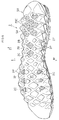
FIG. 3 is a bottom view showing the shoe sole. -
FIG. 4A is a medial side view showing the shoe sole, andFIG. 4B is a lateral side view showing the shoe sole. -
FIG. 5A, FIG. 5B, FIG. 5C, FIG. 5D and FIG. 5E are each a lateral cross-sectional view of the shoe sole. - Preferably, the mid sole 2 across the
convex surface 2F is thicker than thebase 2B around theconvex portion 2P. - In such a case, the
flexible midsole 2 is partially inside thefirst cleats 1C. Therefore, an upthrust is unlikely to be felt from thecleats 1C. - Preferably, the plurality of
first cleats 1C each have a peripheral (outer circumferential)surface 1R extending between thetread surface 10 and thebase 1B; and
a thickness of theoutsole 1 along theperipheral surface 1R decreases as the outsole extends in an upward direction, and increases as the outsole extends in the downward direction. - In such a case, the upper portion of a
first cleat 1C is thinner than the lower portion of thefirst cleat 1C. Now, if an external force in the front-rear direction or in the medial-lateral direction is applied to thefirst cleat 1C, thefirst cleat 1C will likely undergo a shear deformation, which is approximate to a flexural deformation, about the upper end thereof joined with themidsole 2. Then, the largest moment occurs on the thin upper portion, and one can therefore expect that this will increase the deformation of thefirst cleat 1C. - On the other hand, the lower portion of the
first cleats 1C is more likely to come into contact with a hard object or the ground surface, than is the upper portion thereof. However, the lower portion of thefirst cleat 1C, which is relatively thicker than the upper portion thereof, can suppress the deterioration of the durability of thefirst cleats 1C due to such contact. - Preferably, the
first cleats 1C each have anupper edge portion 1E diagonally extending from thebase 1B toward thetread surface 10 and being joined with a peripheral edge of theconvex surface 2F; and
a thickness of theupper edge portion 1E is less than a thickness of thebase 1B. - In such a case, the aforementioned deformation will occur about the
upper edge portion 1E, which is thinner than the thickness of thebase 1B. Therefore, the largest moment occurs on the thinupper edge portion 1E, and one can expect that this will further increase the deformation of thefirst cleat 1C. - Note that the aforementioned thickness relationship may be reversed for some of the many
first cleats 1C provided on theoutsole 1. - Preferably, the
first cleats 1C are arranged on (along) amedial edge 1M and/or alateral edge 1L of the shoe sole, with a side surface of theconvex portion 2P being exposed on themedial edge 1M and/or thelateral edge 1L. - In such a case, the
convex portion 2P of themidsole 2 is exposed on themedial edge 1M and/or thelateral edge 1L, and themedial edge 1M and/or thelateral edge 1L, where theconvex portion 2P of themidsole 2 is exposed, will more easily undergo (show) such a deformation as described above, as compared with a shoe sole with no such exposure. - More preferably, a plurality of the
first cleats 1C are arranged intermittently along amedial edge 1M or alateral edge 1L of the shoe sole, with a side surface of theconvex portion 2P being exposed on themedial edge 1M or thelateral edge 1L; and
an interface between theupper surface 11 of theoutsole 1 and thelower surface 20 of themidsole 2 appears (is displayed) as a wave-shaped (waveform) curve along themedial edge 1M or thelateral edge 1L. - In such a case, the
first cleats 1C, which are arranged intermittently, can easily undergo such a deformation as described above, and one can easily expect the advantageous effect from the deformation. - Even more preferably, a plurality of the
first cleats 1C are arranged intermittently along amedial edge 1M of the shoe sole, with a side surface of theconvex portion 2P being exposed on themedial edge 1M;
an interface between theupper surface 11 of theoutsole 1 and thelower surface 20 of themidsole 2 appears (is displayed) as a wave-shaped (waveform) curve along themedial edge 1M;
a plurality of thefirst cleats 1C are arranged intermittently along alateral edge 1L of the shoe sole, with a side surface of theconvex portion 2P being exposed on thelateral edge 1L;
an interface between theupper surface 11 of theoutsole 1 and thelower surface 20 of themidsole 2 appears as a wave-shaped (waveform) curve along thelateral edge 1L;
the plurality offirst cleats 1C each have a peripheral (outer circumferential)surface 1R extending between thetread surface 10 and thebase 1B; and
a thickness of theoutsole 1 along theperipheral surface 1R decreases as the outsole extends in an upward direction, and increases as the outsole extends in the downward direction. - In such a case, the
first cleats 1C, which easily deform, are arranged intermittently both on themedial edge 1M and on thelateral edge 1L, and one can better expect the advantageous effect from the aforementioned deformation. - Now, in running and trail running, the
upper surface 21 of the midsole sinks in the downward direction generally along the longitudinal axis of the foot, thereby producing a guidance line while running, and one can expect an improvement to the stability while running. (e.g.,US-2011-0185590-A1 ,WO101038266A1 - In the present embodiment, a plurality of
cleats 1C are arranged intermittently both on themedial edge 1M and on thelateral edge 1L. Therefore, themedial edge 1M and thelateral edge 1L will deform (shift, or be displaced) above other positions along the longitudinal axis of the foot while running, and theupper surface 21 of themidsole 2 will sink along the longitudinal axis of the foot. This may improve the stability of running. - Preferably, the
outsole 1 includes three or more of thefirst cleats 1C or a plurality of second cleats other than (separate from) thefirst cleats 1C, with a first through hole H1 being defined in an area surrounded by three or more of the first and/or second cleats; and
the mid sole 2 includes a further (another)first cleat 2C made of the foam body protruding (projecting out) in the downward direction Z through the first through hole H1. - For example, in trail running, a runner runs on a hard ground surface covered with many pebbles or on a slope. When running on the hard ground surface, if all the cleats are hard, the cleats may not easily bite into the hard ground surface, and the many pebbles may not easily bite into between the cleats.
- In a case of this example, the
first cleats 2C, which are made of the foam body (foamed material) of themidsole 2, are much softer than thefirst cleats 1C of theoutsole 1, and pebbles may easily bite into themidsole 2 on the hard ground surface. - On the other hand, the first through holes H1 formed in the
outsole 1 are helpful in reducing the weight of theoutsole 1. - Now, the
midsole 2 and theoutsole 1 are joined (integrated) together, by being bonded or welded together, thereby increasing the thickness, thus significantly increasing the rigidity against flexure, i.e., the flexural rigidity EIz. The flexural rigidity EIz is in proportion to the Young's modulus of the material. Therefore, thefirst cleats 2C of themidsole 2 and the first through holes H1 formed in theoutsole 1 contribute to the lowering of the flexural rigidity EIz, which will improve the bendability of the shoe sole. - Moreover, since the first through holes H1 are provided in the
outsole 1, of which the specific gravity is much larger than that of themidsole 2, it is possible to reduce the weight and it is also more desirable for the environment. - The surface of the
midsole 2 typically has a different color from theoutsole 1 and/or a beautiful texture (appearance), and thecleats 2C of themidsole 2 and theoutsole 1 forming a contrast in color therebetween will be helpful in increasing the design variety of the shoe sole. - Preferably, the
base 1B of theoutsole 1 has a plurality of through holes H2 defined in acentral area 5A of arear foot portion 5R; and
the mid sole 2 includes a plurality of further (other)second cleats 20C made of the foam body and protruding (projecting out) in the downward direction Z through the second through holes H2. - In this case, the second through holes H2 and the
cleats 20C will realize similar effects to the first through hole H1 and the cleats 10C. - Particularly, a plurality of second through holes H2 and
cleats 20C are provided in thecentral area 5A of therear foot portion 5R, which will give therear foot portion 5R a gripping property, and give the heel of therear foot portion 5R an adequate cushioning property. - Preferably, the
outsole 1 includes three or more of thefirst cleats 1C or a plurality of second cleats other than (separate from) thefirst cleats 1C, with a first through hole H1 being defined in an area surrounded by three or more of the first and/or second cleats;
themidsole 2 includes a plurality of further (other)first cleats 2C made of the foam body and protruding (projecting out) in the downward direction Z through the first through hole H1;
thebase 1B of theoutsole 1 has a plurality of second through holes H2 defined in acentral area 5A of arear foot portion 5R;
themidsole 2 includes a plurality of further (other)second cleats 20C made of the foam body and protruding (projecting out) in the downward direction Z through the second through holes H2; and
a total number of first andsecond cleats midsole 2 is set to be 6 to 40. - In such a case, the advantage from the aforementioned deformation will further improve, and the advantageous effect from the cushioning will also be realized.
- The 6 to 40 first and
second cleats midsole 2 will provide novel designs of a shoe sole. - In order to realize the designability and to prevent slippage in trail running, the number of first and
second cleats midsole 2 is preferably 8 to 35, and most preferably about 10 to 30. - Preferably, a Young's modulus of the
outsole 1 is greater than a Young's modulus of themidsole 2. - The hardness of a foamed resin material (foam body of resin) or that of a rubber has a strong correlation with the Young's modulus.
- The
midsole 2 is typically more flexible than theoutsole 1, and the hardness thereof is much smaller than that of theoutsole 1. However, because their hardnesses are measured by using different methods, the concept of Young's modulus is employed instead of their hardness relationship. - Typically, the hardness of the
midsole 2 is set to about 40° to 75° in terms of the asker C hardness. On the other hand, the hardness of theoutsole 1 is set to about 55° to 70° in terms of the JIS-A hardness. Note that 70° in the JIS-A hardness corresponds to about 86° in the asker C hardness. - The present invention will be understood more clearly from the following description of preferred embodiments taken in conjunction with the accompanying drawings. Note however that the embodiments and the drawings are merely illustrative and should not be taken to define the scope of the present invention. The scope of the present invention shall be defined only by the appended claims. In the accompanying drawings, like reference numerals denote like components throughout the plurality of figures.
- An embodiment of the present invention will now be described with reference to the drawings.
- The present embodiment is a shoe sole of a shoe for trail running, for example.
- As shown in
FIG. 2 , the shoe sole includes oneoutsole 1 made of a rubber, and onemidsole 2 made of a resin. Note that an upper (not shown) wrapping around the instep is provided on the shoe sole. - A primary component of the
midsole 2 is a foam body of EVA, for example, and themidsole 2 may include areinforcement unit 29. Themidsole 2 may be provided with a low-resilience material, a high-resilience material, a groove, etc. - The
outsole 1 is a tread bottom having a greater wear resistance than the foam body of themidsole 2, and typically has a greater hardness and a greater Young's modulus than those of the foam body of themidsole 2. Note that "made of a rubber" herein means that it contains a component of a natural rubber or a synthetic rubber, and may contain any other suitable component. - As shown in
FIG. 5A , theoutsole 1 includes thetread surface 10 and theupper surface 11. Themidsole 2 includes theupper surface 21 and thelower surface 20, and thelower surface 20 is attached to theupper surface 11 of theoutsole 1. - The
midsole 2 ofFIG. 1 generally covers the entire surface of the foot sole. On the other hand, theoutsole 1 ofFIG. 2 includes abase portion 1B, and manyfirst cleats 1C and many first and second through holes H1 and H2 formed on thebase portion 1B. Thelower surface 20 of themidsole 2 protrudes through some of the through holes H1 and H2, thereby forming many first andsecond cleats - Note that the first and
second cleats midsole 2 are shaded with dots inFIG. 1 to FIG. 3 . - The
outsole 1 ofFIG. 2 includes a plate-like base 1B and manyfirst cleats 1C. The plurality offirst cleats 1C protrude downward in the downward direction Z from thebase 1B to form thetread surface 10, wherein the plurality offirst cleats 1C are arranged in the longitudinal direction and in the transverse direction. As shown inFIG. 5A , theupper surface 11 of each of thefirst cleats 1C (most of the cleats) includes theconcave surface 1F recessed in the downward direction Z. - The
lower surface 20 of themidsole 2 ofFIG. 1 includes theconvex surface 2F formed by the surface of theconvex portion 2P protruding in the downward direction Z from thebase 2B of themidsole 2. As shown inFIGS. 5A to 5E , theconcave surface 1F and theconvex surface 2F are in contact with each other and are attached (joined by being bonded or welded) together. As clearly shown inFIG. 5A and FIG. 5E , thedistance 1D from thetread surface 10 to the top 2T of theconvex surface 2F in each of thefirst cleats 1C is greater than the thickness Tb of thebase 1B. For example, thedistance 1D shown inFIG. 5A is greater than the average value and the maximum value of the thickness Tb of thebase 1B therearound. As clearly shown inFIG. 5A to FIG. 5E , thefirst cleats 1C and thebase 1B of the present embodiment satisfy one or more of the requirements (1) to (8) defined above. - As clearly shown in
FIG. 5A , themidsole 2 at theconvex surface 2F is thicker than thebase 2B around theconvex portion 2P. Thelower surface 20 of the generallyflat base 2B of themidsole 2 is joined, by being bonded or welded, with theupper surface 11 of the generallyflat base 1B of theoutsole 1. - Note that the line L1 in
FIG. 3 andFIG. 5A to FIG. 5E denotes a reference line. - The plurality of
first cleats 1C ofFIG. 5B each have theperipheral surface 1R extending between thetread surface 10 and thebase 1B. For thefirst cleat 1C on the medial side M inFIG. 5B and FIG. 5E and the centralfirst cleat 1C inFIG. 5E , the thickness of theoutsole 1 along theperipheral surface 1R decreases in the upward direction and increases in the downward direction. - For some of the
first cleats 1C, e.g., thefirst cleat 1C ofFIG. 5A , theperipheral surface 1R has theupper edge portion 1E diagonally extending downward from thebase 1B toward thetread surface 10 and being joined with a peripheral edge of theconvex surface 2F, and the thickness Tr of theupper edge portion 1E is slightly smaller than the thickness Tb of thebase 1B. - As shown in
FIG. 4A and FIG. 4B , many (not all) of thefirst cleats 1C are arranged intermittently along themedial edge 1M and thelateral edge 1L of the shoe sole, with the side surface of theconvex portion 2P being exposed on themedial edge 1M and thelateral edge 1L. Note that inFIG. 4A and FIG. 4B , the side surface of themidsole 2 is shaded with dots. - In
FIG. 4A , many of thefirst cleats 1C are arranged intermittently along themedial edge 1M of the shoe sole, with the side surface of theconvex portion 2P being exposed on themedial edge 1M. Therefore, the interface between theupper surface 11 of theoutsole 1 and thelower surface 20 of themidsole 2 appears, along most (more than half) of the length of themedial edge 1M, as a wave-like continuous curve on themedial edge 1M with theconvex surface 2F being partially exposed. - In
FIG. 4B , many other ones of thefirst cleats 1C are arranged intermittently along thelateral edge 1L of the shoe sole, with the side surface of theconvex portion 2P being exposed on thelateral edge 1L. Therefore, the interface between theupper surface 11 of theoutsole 1 and thelower surface 20 of themidsole 2 appears, along most (more than half) of the length of thelateral edge 1L, as a wave-like continuous curve on thelateral edge 1L with theconvex surface 2F being partially exposed. - By being formed in a wave-like configuration, as described above, the medial and
lateral edges FIG. 5D so that the central portion on the medial side and on the lateral side of themidsole 2 can easily sink in the downward direction. - As shown in
FIG. 1 , the plurality offirst cleats 1C along the side edges 1M and 1L each have theperipheral surface 1R extending between thetread surface 10 and thebase 1B, and the thickness of theoutsole 1 along theperipheral surface 1R decreases in the upward direction and increases in the downward direction as shown inFIG. 5B, FIG. 5C and FIG. 5E . - In
FIG. 2 , each first through hole H1 is formed in a portion of thebase portion 1B surrounded by three or four of thefirst cleats 1C of theoutsole 1. Eachfirst cleat 2C of themidsole 2 protrudes in the downward direction Z through the first through hole H1. - Note that the
outsole 1 may include normal, second cleats, different from thecleats 1C, e.g., cleats with noconcave surface 1F, and the first through holes H1 and thefirst cleats 2C of themidsole 2 may be provided each in an area of thebase 1B surrounded by three or four of the second cleats or thefirst cleats 1C. - As shown in
FIG. 5D andFIG. 2 , in thecentral area 5A of therear foot portion 5R, thebase 1B of theoutsole 1 is formed in a lattice pattern with a few (three) or more through holes H2 formed therein. These second through holes H2 are provided adjacent to each other in thecentral area 5A of therear foot portion 5R of thebase 1B of theoutsole 1. Eachsecond cleat 20C of themidsole 2 protrudes in the downward direction Z through a corresponding one of the second through holes H2. The hardfirst cleats 1C of theoutsole 1 are arranged around (i.e., on the front side, the rear side, the medial side M and the lateral side of) the group ofsecond cleats 20C. Thesefirst cleats 1C are useful in protecting the group ofsecond cleats 20C. - Note that the
central area 5A of therear foot portion 5R means an area of therear foot portion 5R excluding the front and rear ends and the medial andlateral edges rear foot portion 5R. - The total number of first and
second cleats midsole 2 is set to be 10 to 20, for example. - Where the shoe sole of
FIG. 4A and FIG. 4B is under no load, the top 2T of the first andsecond cleats FIG. 1 andFIG. 5D is spaced further away from the ground surface than thetread surface 10 of thefirst cleats 1C of theoutsole 1. Therefore, it will unlikely come into contact with the ground on a flat ground surface, while it will likely come into contact with the ground on a hard ground surface with many pebbles thereon. - As cleats different from the
cleats 1C of theoutsole 1, for example, a small through hole may be provided running through acleat 1C with theconvex surface 2F of themidsole 2 being exposed through the through hole. - Alternatively, the
cleats 2C and thecleats 20C may not be protruding through the first through holes H1 and the second through holes H2 of themidsole 2 ofFIG. 2 , and the flatlower surface 20 of thebase 2B of themidsole 2 may instead be exposed through the first through holes H1, etc. - While preferred embodiments have been described above with reference to the drawings, various obvious changes and modifications will readily occur to those skilled in the art upon reading the present specification.
- For example, the
reinforcement unit 29 may be absent (not be provided). Grooves may be provided around cleats of the outsole. The midsole and/or the outsole may each be formed by a plurality of layers of member. - Thus, such changes and modifications are deemed to fall within the scope of the present invention, which is defined by the appended claims.
- The present invention is applicable to the shoe sole of walking shoes, rain shoes and shoes of daily use, as well as to the shoe sole of athletic shoes, such as trail running shoes, mountain climbing shoes and cross country shoes.
-
- 1: Outsole, 1B: Base, 1C: First cleat, 1D: Distance, 1E: Upper edge portion, 1F: Concave surface, 1M: Medial edge, 1L: Lateral edge, 1R: Peripheral surface, 10: Tread surface, 11: Upper surface
- 2: Midsole, 2B: Base, 2C: First cleat, 20C: Second cleat, 2F: Convex surface, 2P: Convex portion, 2T: Top, 20: Lower surface, 21: Upper surface, 29: Reinforcement unit
- 5R: Rear foot portion, 5A: Central area
- H1: First through hole, H2: Second through hole
- L: Lateral side, L1: Reference line, M: Medial side
- Z: Downward direction
Claims (12)
- A shoe sole comprising:an outsole 1 made of a rubber having a tread surface 10 and an upper surface 11; anda mid sole 2 having an upper surface 21 and a lower surface 20, wherein the lower surface 20 is attached to the upper surface 11 of the outsole 1, and a main component of the mid sole 2 is a foam body having a thermoplastic resin component, wherein:the outsole 1 includes:a base 1B;a plurality of first cleats 1C protruding in a downward direction Z from the base 1B to form the tread surface 10, wherein the plurality of first cleats 1C are arranged in a longitudinal direction and in a transverse direction; anda concave surface 1F recessed in the downward direction Z on the upper surface 11 of each of the first cleats 1C;the lower surface 20 of the mid sole 2 includes a convex surface 2F formed by a surface of a convex portion 2P protruding in the downward direction Z from a base 2B of the mid sole 2;the concave surface 1F and the convex surface 2F are in contact with, and attached to, each other; anda distance 1D from the tread surface 10 to a top 2T of the convex surface 2F in each of the first cleats 1C is greater than a thickness of the base 1B.
- The shoe sole according to claim 1, wherein:the mid sole 2 across the convex surface 2F is thicker than the base 2B around the convex portion 2P.
- The shoe sole according to claim 1 or 2, wherein:the plurality of first cleats 1C each have a peripheral surface 1R extending between the tread surface 10 and the base 1B; anda thickness of the outsole 1 along the peripheral surface 1R decreases in an upward direction and increases in the downward direction.
- The shoe sole according to claim 1, 2 or 3, wherein:the first cleats 1C each have an upper edge portion 1E diagonally extending from the base 1B toward the tread surface 10 and being joined with a peripheral edge of the convex surface 2F; anda thickness of the upper edge portion 1E is less than a thickness of the base 1B.
- The shoe sole according to any one of claims 1 to 4, wherein:the first cleats 1C are arranged on a medial edge 1M and/or a lateral edge 1L of the shoe sole, with a side surface of the convex portion 2P being exposed on the medial edge 1M and/or the lateral edge 1L.
- The shoe sole according to any one of claims 1 to 4, wherein:a plurality of the first cleats 1C are arranged intermittently along a medial edge 1M or a lateral edge 1L of the shoe sole, with a side surface of the convex portion 2P being exposed on the medial edge 1M or the lateral edge 1L; andan interface between the upper surface 11 of the outsole 1 and the lower surface 20 of the midsole 2 appears as a wave-shaped curve along the medial edge 1M or the lateral edge 1L.
- The shoe sole according to any one of claims 1 to 4, wherein:a plurality of the first cleats 1C are arranged intermittently along a medial edge 1M of the shoe sole, with a side surface of the convex portion 2P being exposed on the medial edge 1M;an interface between the upper surface 11 of the outsole 1 and the lower surface 20 of the midsole 2 appears as a wave-shaped curve along the medial edge 1M;a plurality of the first cleats 1C are arranged intermittently along a lateral edge 1L of the shoe sole, with a side surface of the convex portion 2P being exposed on the lateral edge 1L;the interface between the upper surface 11 of the outsole 1 and the lower surface 20 of the midsole 2 appears as a wave-shaped curve along the lateral edge 1L;the plurality of first cleats 1C each have a peripheral surface 1R extending between the tread surface 10 and the base 1B; anda thickness of the outsole 1 along the peripheral surface 1R decreases in an upward direction and increases in the downward direction.
- The shoe sole according to any one of claims 1 to 7, wherein:the outsole 1 includes three or more of the first cleats 1C or a plurality of second cleats other than the first cleats 1C, with a first through hole H1 being defined in an area surrounded by three or more of the first and/or second cleats; andthe mid sole 2 includes a further first cleat 2C made of the foam body protruding in the downward direction Z through the first through hole H1.
- The shoe sole according to any one of claims 1 to 8, wherein:the base 1B of the outsole 1 defines a plurality of through holes H2 in a central area 5A of a rear foot portion 5R; andthe mid sole 2 includes a plurality of further second cleats 20C made of the foam body and protruding in the downward direction Z through the second through holes H2.
- The shoe sole according to any one of claims 1 to 7, wherein:the outsole 1 includes three or more of the first cleats 1C or a plurality of second cleats other than the first cleats 1C, with a first through hole H1 being defined in an area surrounded by three or more of the first and/or second cleats;the midsole 2 includes a plurality of further first cleats 2C made of the foam body and protruding in the downward direction Z through the first through hole H1;the base 1B of the outsole 1 defines a plurality of second through holes H2 in a central area 5A of a rear foot portion 5R;the midsole 2 includes a plurality of further second cleats 20C made of the foam body and protruding in the downward direction Z through the second through holes H2; anda total number of first and second cleats 2C and 20C of the midsole 2 is set to be 6 to 40.
- The shoe sole according to claim 8 or 9, wherein:where the shoe sole is under no load,tops 2T of the first and second cleats 2C and 20C made of the foam body are spaced further away from the ground surface than the tread surface 10 of the first and second cleats 1C and 10C of the outsole 1.
- The shoe sole according to any one of claims 1 to 11, wherein:a Young's modulus of the outsole 1 is greater than a Young's modulus of the midsole 2.
Applications Claiming Priority (1)
| Application Number | Priority Date | Filing Date | Title |
|---|---|---|---|
| PCT/JP2013/077631 WO2015052814A1 (en) | 2013-10-10 | 2013-10-10 | Shoe sole |
Publications (3)
| Publication Number | Publication Date |
|---|---|
| EP3056104A1 true EP3056104A1 (en) | 2016-08-17 |
| EP3056104A4 EP3056104A4 (en) | 2017-06-28 |
| EP3056104B1 EP3056104B1 (en) | 2020-04-15 |
Family
ID=52812661
Family Applications (1)
| Application Number | Title | Priority Date | Filing Date |
|---|---|---|---|
| EP13895346.8A Active EP3056104B1 (en) | 2013-10-10 | 2013-10-10 | Shoe sole |
Country Status (4)
| Country | Link |
|---|---|
| US (1) | US9867427B2 (en) |
| EP (1) | EP3056104B1 (en) |
| JP (1) | JP6055554B2 (en) |
| WO (1) | WO2015052814A1 (en) |
Families Citing this family (71)
| Publication number | Priority date | Publication date | Assignee | Title |
|---|---|---|---|---|
| JP5756893B2 (en) | 2013-05-01 | 2015-07-29 | 株式会社アシックス | Sole material |
| US10159306B2 (en) * | 2013-10-10 | 2018-12-25 | Asics Corporation | Shoe sole |
| USD749310S1 (en) | 2013-12-13 | 2016-02-16 | Reebok International Limited | Shoe |
| USD744212S1 (en) | 2013-12-13 | 2015-12-01 | Reebok International Limited | Shoe |
| US9687044B2 (en) | 2014-07-24 | 2017-06-27 | Nike, Inc. | Footwear with sole structure incorporating lobed fluid-filled chamber with protruding end wall portions |
| DE102015208763A1 (en) * | 2015-05-12 | 2016-11-17 | Adidas Ag | Adjustable shoe upper and customizable sole |
| WO2017087772A1 (en) | 2015-11-20 | 2017-05-26 | Nike Innovate C.V. | Ground-engaging structures for articles of footwear |
| USD779174S1 (en) * | 2015-12-22 | 2017-02-21 | Nike, Inc. | Shoe midsole |
| US20170224053A1 (en) * | 2016-02-05 | 2017-08-10 | Ecco Sko A/S | Outer sole for spikeless footwear |
| USD814156S1 (en) * | 2016-03-09 | 2018-04-03 | Under Armour, Inc. | Shoe sole |
| USD804157S1 (en) * | 2016-05-15 | 2017-12-05 | Nike, Inc. | Shoe midsole |
| USD824147S1 (en) * | 2016-05-16 | 2018-07-31 | Nike, Inc. | Shoe |
| USD794299S1 (en) * | 2016-06-30 | 2017-08-15 | Nike, Inc. | Shoe outsole |
| USD862051S1 (en) | 2016-07-18 | 2019-10-08 | Adidas Ag | Sole |
| USD814758S1 (en) * | 2016-08-15 | 2018-04-10 | Ecco Sko A/S | Sole |
| USD808625S1 (en) * | 2016-08-15 | 2018-01-30 | Nike, Inc. | Shoe outsole |
| USD862052S1 (en) * | 2016-09-08 | 2019-10-08 | Decathlon | Footwear with surface pattern |
| USD821717S1 (en) * | 2016-09-12 | 2018-07-03 | Under Armour, Inc. | Sole structure |
| USD811063S1 (en) * | 2016-11-12 | 2018-02-27 | Nike, Inc. | Shoe outsole |
| USD808140S1 (en) * | 2016-11-14 | 2018-01-23 | Nike, Inc. | Shoe outsole |
| US11019884B2 (en) * | 2016-11-23 | 2021-06-01 | Nike, Inc. | Sole structure having a midsole component with movable traction members |
| USD801014S1 (en) * | 2016-12-05 | 2017-10-31 | Converse Inc. | Shoe midsole |
| IT201600130908A1 (en) * | 2016-12-23 | 2018-06-23 | Alberto Del Biondi S P A | Footwear with midsole |
| US11752413B2 (en) * | 2016-12-31 | 2023-09-12 | Under Armour, Inc. | Article of footwear with multiple durometer outsole and directional cleat pattern |
| USD848131S1 (en) * | 2017-02-01 | 2019-05-14 | Fuerst Group, Inc. | Outsole for a footwear article |
| USD821719S1 (en) * | 2017-02-13 | 2018-07-03 | Nike, Inc. | Shoe outsole |
| USD829424S1 (en) * | 2017-03-06 | 2018-10-02 | Nike, Inc. | Shoe outsole |
| USD831318S1 (en) * | 2017-03-31 | 2018-10-23 | Christian Louboutin | Shoe sole |
| USD826527S1 (en) * | 2017-04-05 | 2018-08-28 | Nike, Inc. | Shoe outsole |
| USD832563S1 (en) * | 2017-04-14 | 2018-11-06 | Nike, Inc. | Shoe outsole |
| USD824152S1 (en) * | 2017-04-14 | 2018-07-31 | Nike, Inc. | Shoe outsole |
| USD823584S1 (en) * | 2017-04-14 | 2018-07-24 | Nike, Inc. | Shoe outsole |
| USD852483S1 (en) * | 2017-04-28 | 2019-07-02 | Vans, Inc. | Shoe outsole |
| US10952496B2 (en) | 2017-05-09 | 2021-03-23 | Under Armour, Inc. | Article of footwear with interlocking midsole member |
| USD836312S1 (en) * | 2017-05-15 | 2018-12-25 | Under Armour, Inc. | Article of footwear |
| USD826528S1 (en) * | 2017-05-15 | 2018-08-28 | Nike, Inc. | Shoe outsole |
| USD816965S1 (en) * | 2017-10-11 | 2018-05-08 | Skechers U.S.A., Inc. Ii | Shoe outsole bottom |
| USD818254S1 (en) * | 2017-10-12 | 2018-05-22 | Skechers U.S.A., Inc. Ii | Shoe outsole bottom |
| CN210581223U (en) * | 2017-10-13 | 2020-05-22 | 株式会社爱世克私 | Soles and Shoes |
| USD841964S1 (en) * | 2017-11-10 | 2019-03-05 | Reebok International Limited | Sole |
| USD822351S1 (en) * | 2017-12-19 | 2018-07-10 | Nike, Inc. | Shoe |
| USD863743S1 (en) | 2018-01-09 | 2019-10-22 | Adidas Ag | Shoe |
| USD889788S1 (en) * | 2018-02-23 | 2020-07-14 | Sumitomo Rubber Industries, Ltd. | Shoe midsole |
| USD901154S1 (en) * | 2018-05-04 | 2020-11-10 | J & B Yang Corporation | Slip resistant outsole |
| USD872983S1 (en) | 2018-06-20 | 2020-01-21 | Christian Louboutin | Sole for footwear |
| USD879438S1 (en) | 2018-08-09 | 2020-03-31 | Reebok International Limited | Shoe |
| USD879437S1 (en) | 2018-08-09 | 2020-03-31 | Reebok International Limited | Shoe |
| USD879427S1 (en) * | 2018-11-09 | 2020-03-31 | J. Choo Limited | Sole for footwear |
| USD889099S1 (en) * | 2018-11-09 | 2020-07-07 | J. Choo Limited | Sole for footwear |
| US12171300B2 (en) * | 2019-03-28 | 2024-12-24 | Nike, Inc. | Sole structure of an article of footwear |
| CN210611192U (en) * | 2019-04-03 | 2020-05-26 | 霍尼韦尔国际公司 | Footwear outsole with resistance elements |
| USD929722S1 (en) * | 2019-05-15 | 2021-09-07 | Fly Kytin Corp. | Sole for footwear |
| USD900443S1 (en) * | 2019-05-17 | 2020-11-03 | Nike, Inc. | Shoe |
| USD912376S1 (en) * | 2019-07-18 | 2021-03-09 | You Rao | Footwear sole |
| USD917138S1 (en) * | 2019-08-27 | 2021-04-27 | Deckers Outdoor Corporation | Footwear midsole |
| USD934536S1 (en) * | 2020-03-10 | 2021-11-02 | Paloise Sas | Footwear |
| EP4178393A1 (en) * | 2020-07-13 | 2023-05-17 | NIKE Innovate C.V. | Sole structure with midsole protrusions and arced profile for forward momentum |
| USD950217S1 (en) * | 2020-12-08 | 2022-05-03 | J. Choo Limited | Sole for footwear |
| USD977797S1 (en) * | 2020-12-09 | 2023-02-14 | Converse Inc. | Shoe |
| USD978509S1 (en) * | 2020-12-09 | 2023-02-21 | Converse Inc. | Shoe |
| USD950912S1 (en) * | 2020-12-29 | 2022-05-10 | J. Choo Limited | Sole for footwear |
| WO2022224348A1 (en) * | 2021-04-20 | 2022-10-27 | 株式会社アシックス | Shoe sole and shoe |
| USD1103598S1 (en) * | 2021-05-25 | 2025-12-02 | Jiawei Lin | Running shoe |
| USD996002S1 (en) * | 2021-07-22 | 2023-08-22 | Valentino S.P.A. | Shoe |
| JP1754171S (en) | 2021-08-05 | 2023-09-29 | shoes | |
| USD1010996S1 (en) * | 2021-08-19 | 2024-01-16 | Converse Inc. | Shoe |
| USD980601S1 (en) * | 2021-11-05 | 2023-03-14 | Chenliang Zhong | Shoe sole |
| USD981096S1 (en) * | 2021-11-22 | 2023-03-21 | Guohai Wang | Sole |
| USD1116391S1 (en) * | 2022-01-20 | 2026-03-10 | Zackary Zenon Contreras | Snakeskin patterned sole for sandals and other shoes |
| USD994290S1 (en) * | 2022-08-03 | 2023-08-08 | Hui Jiang | Outsole |
| USD1111374S1 (en) * | 2023-05-23 | 2026-02-10 | Louis Vuitton Malletier | Sole for footwear |
Family Cites Families (78)
| Publication number | Priority date | Publication date | Assignee | Title |
|---|---|---|---|---|
| FR2374863A1 (en) * | 1976-07-29 | 1978-07-21 | Adidas Chaussures | SOLE FOR SPORTS AND LEISURE SHOES |
| JPS5690105A (en) | 1979-12-24 | 1981-07-22 | Kayaba Ind Co Ltd | Controlling valve for farm working machinery of agricultural tractor |
| US4481727A (en) * | 1980-05-06 | 1984-11-13 | Pensa, Inc. | Shoe sole construction |
| JPS5745851Y2 (en) * | 1980-11-27 | 1982-10-08 | ||
| FR2632497A1 (en) * | 1988-03-22 | 1989-12-15 | Beneteau Charles Marie | SOLE OF SHOES FOR THE PRACTICE OF SPORTS AND SIMILAR ACTIVITIES |
| JPH0438701A (en) | 1990-06-01 | 1992-02-07 | Toshiba Corp | Magnetic reacording/reproducing device |
| JPH0438701U (en) | 1990-07-30 | 1992-04-02 | ||
| US5155927A (en) | 1991-02-20 | 1992-10-20 | Asics Corporation | Shoe comprising liquid cushioning element |
| JP3350863B2 (en) | 1991-04-26 | 2002-11-25 | ダウ・ケミカル日本株式会社 | Granule composition for paddy field weeding |
| JPH0565201U (en) | 1992-02-17 | 1993-08-31 | 月星化成株式会社 | Injection molded boots |
| US5367791A (en) * | 1993-02-04 | 1994-11-29 | Asahi, Inc. | Shoe sole |
| JPH07265103A (en) | 1993-12-28 | 1995-10-17 | Midori Anzen Co Ltd | Shoe sole and manufacturing method thereof |
| US5718063A (en) | 1995-07-17 | 1998-02-17 | Asics Corporation | Midsole cushioning system |
| JPH11137305A (en) * | 1997-11-11 | 1999-05-25 | Bridgestone Sports Co Ltd | Sports shoes |
| JP3258628B2 (en) | 1998-09-08 | 2002-02-18 | 株式会社アシックス | Athletic shoes |
| JP3238132B2 (en) * | 1998-10-02 | 2001-12-10 | 美津濃株式会社 | Midsole structure for sports shoes |
| JP3396637B2 (en) | 1998-11-05 | 2003-04-14 | 株式会社アシックス | Support structure for shank on sole |
| US6438870B2 (en) | 1998-11-05 | 2002-08-27 | Asics Corporation | Shoe sole with shock absorber structure |
| US6467197B1 (en) | 1999-05-31 | 2002-10-22 | Asics Corp. | Shoe with arch reinforcement |
| JP2001046113A (en) * | 1999-08-11 | 2001-02-20 | Descente Ltd | Spike shoes sole |
| JP4076704B2 (en) | 2000-05-09 | 2008-04-16 | 美津濃株式会社 | Sole structure of sports shoes |
| JP3979765B2 (en) | 2000-05-15 | 2007-09-19 | 株式会社アシックス | Shoe sole shock absorber |
| JP3921453B2 (en) | 2003-04-04 | 2007-05-30 | 株式会社アシックス | Foot inclination measuring method, shoe or insole selection method, shoe or insole manufacturing method, and foot inclination measuring device |
| USD522229S1 (en) | 2003-07-18 | 2006-06-06 | Asics Corp. | Pair of shoe midsoles |
| USD496148S1 (en) | 2003-07-18 | 2004-09-21 | Asics Corporation | Pair of shoe outsoles |
| USD501713S1 (en) | 2003-07-18 | 2005-02-15 | As/Cs Corporation | Shoe midsole |
| USD495860S1 (en) | 2003-07-18 | 2004-09-14 | Asics Corp | Shoe outsole |
| USD501987S1 (en) | 2003-08-20 | 2005-02-22 | Asics Corporation | Shoe midsole |
| USD495859S1 (en) | 2003-08-20 | 2004-09-14 | Asics Corporation | Pair of shoe outsoles |
| AU2004281112C1 (en) | 2003-10-17 | 2009-01-08 | Asics Corporation | Sole with reinforcement structure |
| US7322131B2 (en) | 2003-11-27 | 2008-01-29 | Asics Corp. | Shoe with slip preventive member |
| JP3929439B2 (en) | 2003-12-24 | 2007-06-13 | 株式会社アシックス | Spike shoes sole |
| USD520732S1 (en) | 2004-05-27 | 2006-05-16 | Asics Corporation | Pair of shoe midsoles |
| USD512819S1 (en) | 2004-05-27 | 2005-12-20 | Asics Corporation | Pair of shoe outsoles |
| USD512827S1 (en) | 2004-05-27 | 2005-12-20 | Asics Corporation | Pair of shoe midsoles |
| USD512828S1 (en) | 2004-05-27 | 2005-12-20 | Asics Corporation | Pair of shoe midsoles |
| USD512818S1 (en) | 2004-05-27 | 2005-12-20 | Asics Corp. | Pair of shoe outsoles |
| USD512208S1 (en) | 2004-05-27 | 2005-12-06 | Asics Corporation | Pair of shoe outsoles |
| US7877899B2 (en) | 2004-09-30 | 2011-02-01 | Asics Corporation | Shock absorbing device for shoe sole in rear foot part |
| US7779558B2 (en) | 2004-09-30 | 2010-08-24 | Asics Corporation | Shock absorbing device for shoe sole |
| USD514286S1 (en) | 2004-11-15 | 2006-02-07 | Asics Corporation | Pair of shoe outsoles |
| USD513115S1 (en) | 2004-11-15 | 2005-12-27 | Asics Corporation | Pair of shoe midsoles |
| USD509351S1 (en) | 2004-11-15 | 2005-09-13 | Asics Corporation | Shoe midsole |
| USD575946S1 (en) | 2005-03-29 | 2008-09-02 | Asics Corporation | Pair of heels for shoe outsoles |
| USD553846S1 (en) | 2005-04-26 | 2007-10-30 | Asics Corporation | Shoe outsole and midsole |
| US8008363B2 (en) | 2005-05-10 | 2011-08-30 | Asics Corporation | Shoe sole component |
| JP4704429B2 (en) | 2005-05-13 | 2011-06-15 | 株式会社アシックス | Shoe sole shock absorber |
| KR100683242B1 (en) * | 2005-06-03 | 2007-02-15 | 주식회사 트렉스타 | Shoe soles |
| USD542522S1 (en) | 2005-10-11 | 2007-05-15 | Asics Corporation | Shoe midsole |
| WO2007046277A1 (en) | 2005-10-20 | 2007-04-26 | Asics Corporation | Sole with reinforcement structure |
| JP3120866U (en) * | 2006-02-06 | 2006-04-20 | 株式会社シモン | Shoe outsole structure with excellent slip and aging resistance |
| JP4886774B2 (en) | 2006-04-21 | 2012-02-29 | 株式会社アシックス | Sole with reinforced structure and sole with shock absorbing structure |
| USD552833S1 (en) | 2006-05-05 | 2007-10-16 | Asics Corp. | Shoe |
| JP5001579B2 (en) * | 2006-05-23 | 2012-08-15 | 株式会社アシックス | Stud and spike shoes |
| USD561434S1 (en) | 2006-08-01 | 2008-02-12 | Asics Corp. | Pair of shoe outsoles |
| USD561442S1 (en) | 2006-08-01 | 2008-02-12 | Asics Corp. | Pair of shoe outsoles |
| US9089185B2 (en) | 2006-10-20 | 2015-07-28 | Asics Corporation | Structure of front foot portion of shoe sole |
| USD582658S1 (en) | 2007-04-06 | 2008-12-16 | Asics Corporation | Shoe |
| USD575486S1 (en) | 2007-05-11 | 2008-08-26 | Asics Corporation | Pair of shoe outsoles |
| US7941941B2 (en) * | 2007-07-13 | 2011-05-17 | Nike, Inc. | Article of footwear incorporating foam-filled elements and methods for manufacturing the foam-filled elements |
| USD571090S1 (en) | 2007-07-17 | 2008-06-17 | Asics Corporation | Pair of shoe outsoles |
| WO2010038266A1 (en) | 2008-09-30 | 2010-04-08 | 株式会社アシックス | Sole of sports shoes exhibiting good running efficiency |
| US8220185B2 (en) * | 2009-01-29 | 2012-07-17 | Nike, Inc. | Article of footwear with suspended stud assembly |
| US8171655B2 (en) * | 2009-03-18 | 2012-05-08 | Wolverine World Wide, Inc. | Sole construction and related method of manufacture |
| USD650566S1 (en) | 2010-05-07 | 2011-12-20 | Asics Corporation | Shoe |
| US9210967B2 (en) * | 2010-08-13 | 2015-12-15 | Nike, Inc. | Sole structure with traction elements |
| EP2687116A4 (en) | 2011-03-18 | 2015-05-06 | Asics Corp | Reinforcing fiber-reinforced spike sole |
| US8931187B2 (en) * | 2011-08-25 | 2015-01-13 | Tbl Licensing Llc | Wave technology |
| JP5749358B2 (en) | 2012-01-18 | 2015-07-15 | 株式会社アシックス | Foam sole and shoes |
| EP2815668B1 (en) | 2012-02-17 | 2019-02-06 | ASICS Corporation | Shoe and manufacturing method therefor |
| US20150135558A1 (en) | 2012-05-10 | 2015-05-21 | Asics Corporation | Shoe Sole Having Diagonal Groove |
| US9775402B2 (en) | 2012-05-10 | 2017-10-03 | Asics Corporation | Shoe sole having outsole and midsole |
| WO2013179455A1 (en) | 2012-05-31 | 2013-12-05 | 株式会社アシックス | Molded foam article, foam sole, and shoes |
| US20150250260A1 (en) | 2012-10-29 | 2015-09-10 | Asics Corporation | Shoe Sole Focusing on Windlass Mechanism |
| JP5442170B1 (en) | 2013-01-24 | 2014-03-12 | 株式会社アシックス | Shoes and manufacturing method thereof |
| WO2014141467A1 (en) | 2013-03-15 | 2014-09-18 | 株式会社アシックス | Midsole having a laminated structure |
| USD734928S1 (en) | 2013-03-28 | 2015-07-28 | Asics Corporation | Footwear sole |
| USD734927S1 (en) | 2013-03-28 | 2015-07-28 | Asics Corporation | Footwear sole |
-
2013
- 2013-10-10 US US15/027,679 patent/US9867427B2/en active Active
- 2013-10-10 EP EP13895346.8A patent/EP3056104B1/en active Active
- 2013-10-10 JP JP2015541383A patent/JP6055554B2/en not_active Expired - Fee Related
- 2013-10-10 WO PCT/JP2013/077631 patent/WO2015052814A1/en not_active Ceased
Also Published As
| Publication number | Publication date |
|---|---|
| US9867427B2 (en) | 2018-01-16 |
| JPWO2015052814A1 (en) | 2017-03-09 |
| JP6055554B2 (en) | 2016-12-27 |
| EP3056104A4 (en) | 2017-06-28 |
| US20160255911A1 (en) | 2016-09-08 |
| WO2015052814A1 (en) | 2015-04-16 |
| EP3056104B1 (en) | 2020-04-15 |
Similar Documents
| Publication | Publication Date | Title |
|---|---|---|
| EP3056104B1 (en) | Shoe sole | |
| EP3056103B1 (en) | Shoe sole | |
| US11058174B2 (en) | Footwear sole structure | |
| US7647709B2 (en) | Footwear with a shank system | |
| JP6310427B2 (en) | Sole structure of shoes | |
| EP3777593B1 (en) | Shoe sole including laminate-structured midsole | |
| US8621767B2 (en) | Article of footwear having a support structure | |
| US9526298B2 (en) | Footwear with improved sole assembly | |
| EP1765104B1 (en) | Article of footwear with sole plate | |
| JP5355409B2 (en) | Sole structure for energy storage and recovery | |
| AU2008362408B2 (en) | Shoe sole of athletic shoe with high running efficiency | |
| CN101828793A (en) | Shoe with improved bottom assembly | |
| WO2008039601A1 (en) | Article of footwear for long jumping | |
| US20070130801A1 (en) | Combination outsole and friction sheet | |
| WO2017163741A1 (en) | Shoe sole structure and shoe using same | |
| JP2004242692A (en) | Sports shoe sole assembly | |
| JP2013135702A (en) | Sole structure | |
| JP5687451B2 (en) | shoes | |
| CN201948105U (en) | Anti-slip and wear-resistant sole | |
| US20250302149A1 (en) | Sole structure and shoe including the sole structure | |
| CN207477045U (en) | A kind of stable beach shoes of walking | |
| JP3112367U (en) | Festival Tabi and Insole | |
| JP2005270270A (en) | insole |
Legal Events
| Date | Code | Title | Description |
|---|---|---|---|
| PUAI | Public reference made under article 153(3) epc to a published international application that has entered the european phase |
Free format text: ORIGINAL CODE: 0009012 |
|
| 17P | Request for examination filed |
Effective date: 20160331 |
|
| AK | Designated contracting states |
Kind code of ref document: A1 Designated state(s): AL AT BE BG CH CY CZ DE DK EE ES FI FR GB GR HR HU IE IS IT LI LT LU LV MC MK MT NL NO PL PT RO RS SE SI SK SM TR |
|
| AX | Request for extension of the european patent |
Extension state: BA ME |
|
| DAX | Request for extension of the european patent (deleted) | ||
| A4 | Supplementary search report drawn up and despatched |
Effective date: 20170526 |
|
| RIC1 | Information provided on ipc code assigned before grant |
Ipc: A43B 13/18 20060101ALI20170519BHEP Ipc: A43B 13/26 20060101ALI20170519BHEP Ipc: A43C 15/02 20060101ALI20170519BHEP Ipc: A43B 5/06 20060101ALI20170519BHEP Ipc: A43B 13/14 20060101ALI20170519BHEP Ipc: A43B 13/04 20060101ALI20170519BHEP Ipc: A43B 13/12 20060101ALI20170519BHEP Ipc: A43C 15/16 20060101ALI20170519BHEP Ipc: A43B 13/22 20060101AFI20170519BHEP Ipc: A43C 13/04 20060101ALI20170519BHEP |
|
| RIN1 | Information on inventor provided before grant (corrected) |
Inventor name: FUJITA, YOSHINORI Inventor name: HAYASHI, SEIYA Inventor name: TAKEMURA, SYUHEI |
|
| STAA | Information on the status of an ep patent application or granted ep patent |
Free format text: STATUS: EXAMINATION IS IN PROGRESS |
|
| 17Q | First examination report despatched |
Effective date: 20190808 |
|
| GRAP | Despatch of communication of intention to grant a patent |
Free format text: ORIGINAL CODE: EPIDOSNIGR1 |
|
| STAA | Information on the status of an ep patent application or granted ep patent |
Free format text: STATUS: GRANT OF PATENT IS INTENDED |
|
| INTG | Intention to grant announced |
Effective date: 20191211 |
|
| GRAS | Grant fee paid |
Free format text: ORIGINAL CODE: EPIDOSNIGR3 |
|
| GRAA | (expected) grant |
Free format text: ORIGINAL CODE: 0009210 |
|
| STAA | Information on the status of an ep patent application or granted ep patent |
Free format text: STATUS: THE PATENT HAS BEEN GRANTED |
|
| AK | Designated contracting states |
Kind code of ref document: B1 Designated state(s): AL AT BE BG CH CY CZ DE DK EE ES FI FR GB GR HR HU IE IS IT LI LT LU LV MC MK MT NL NO PL PT RO RS SE SI SK SM TR |
|
| REG | Reference to a national code |
Ref country code: CH Ref legal event code: EP |
|
| REG | Reference to a national code |
Ref country code: DE Ref legal event code: R096 Ref document number: 602013068062 Country of ref document: DE |
|
| REG | Reference to a national code |
Ref country code: IE Ref legal event code: FG4D |
|
| REG | Reference to a national code |
Ref country code: AT Ref legal event code: REF Ref document number: 1256272 Country of ref document: AT Kind code of ref document: T Effective date: 20200515 |
|
| REG | Reference to a national code |
Ref country code: NL Ref legal event code: MP Effective date: 20200415 |
|
| REG | Reference to a national code |
Ref country code: LT Ref legal event code: MG4D |
|
| PG25 | Lapsed in a contracting state [announced via postgrant information from national office to epo] |
Ref country code: GR Free format text: LAPSE BECAUSE OF FAILURE TO SUBMIT A TRANSLATION OF THE DESCRIPTION OR TO PAY THE FEE WITHIN THE PRESCRIBED TIME-LIMIT Effective date: 20200716 Ref country code: FI Free format text: LAPSE BECAUSE OF FAILURE TO SUBMIT A TRANSLATION OF THE DESCRIPTION OR TO PAY THE FEE WITHIN THE PRESCRIBED TIME-LIMIT Effective date: 20200415 Ref country code: SE Free format text: LAPSE BECAUSE OF FAILURE TO SUBMIT A TRANSLATION OF THE DESCRIPTION OR TO PAY THE FEE WITHIN THE PRESCRIBED TIME-LIMIT Effective date: 20200415 Ref country code: NO Free format text: LAPSE BECAUSE OF FAILURE TO SUBMIT A TRANSLATION OF THE DESCRIPTION OR TO PAY THE FEE WITHIN THE PRESCRIBED TIME-LIMIT Effective date: 20200715 Ref country code: IS Free format text: LAPSE BECAUSE OF FAILURE TO SUBMIT A TRANSLATION OF THE DESCRIPTION OR TO PAY THE FEE WITHIN THE PRESCRIBED TIME-LIMIT Effective date: 20200815 Ref country code: LT Free format text: LAPSE BECAUSE OF FAILURE TO SUBMIT A TRANSLATION OF THE DESCRIPTION OR TO PAY THE FEE WITHIN THE PRESCRIBED TIME-LIMIT Effective date: 20200415 Ref country code: NL Free format text: LAPSE BECAUSE OF FAILURE TO SUBMIT A TRANSLATION OF THE DESCRIPTION OR TO PAY THE FEE WITHIN THE PRESCRIBED TIME-LIMIT Effective date: 20200415 Ref country code: PT Free format text: LAPSE BECAUSE OF FAILURE TO SUBMIT A TRANSLATION OF THE DESCRIPTION OR TO PAY THE FEE WITHIN THE PRESCRIBED TIME-LIMIT Effective date: 20200817 |
|
| REG | Reference to a national code |
Ref country code: AT Ref legal event code: MK05 Ref document number: 1256272 Country of ref document: AT Kind code of ref document: T Effective date: 20200415 |
|
| PG25 | Lapsed in a contracting state [announced via postgrant information from national office to epo] |
Ref country code: HR Free format text: LAPSE BECAUSE OF FAILURE TO SUBMIT A TRANSLATION OF THE DESCRIPTION OR TO PAY THE FEE WITHIN THE PRESCRIBED TIME-LIMIT Effective date: 20200415 Ref country code: BG Free format text: LAPSE BECAUSE OF FAILURE TO SUBMIT A TRANSLATION OF THE DESCRIPTION OR TO PAY THE FEE WITHIN THE PRESCRIBED TIME-LIMIT Effective date: 20200715 Ref country code: RS Free format text: LAPSE BECAUSE OF FAILURE TO SUBMIT A TRANSLATION OF THE DESCRIPTION OR TO PAY THE FEE WITHIN THE PRESCRIBED TIME-LIMIT Effective date: 20200415 Ref country code: LV Free format text: LAPSE BECAUSE OF FAILURE TO SUBMIT A TRANSLATION OF THE DESCRIPTION OR TO PAY THE FEE WITHIN THE PRESCRIBED TIME-LIMIT Effective date: 20200415 |
|
| PG25 | Lapsed in a contracting state [announced via postgrant information from national office to epo] |
Ref country code: AL Free format text: LAPSE BECAUSE OF FAILURE TO SUBMIT A TRANSLATION OF THE DESCRIPTION OR TO PAY THE FEE WITHIN THE PRESCRIBED TIME-LIMIT Effective date: 20200415 |
|
| REG | Reference to a national code |
Ref country code: DE Ref legal event code: R097 Ref document number: 602013068062 Country of ref document: DE |
|
| PG25 | Lapsed in a contracting state [announced via postgrant information from national office to epo] |
Ref country code: ES Free format text: LAPSE BECAUSE OF FAILURE TO SUBMIT A TRANSLATION OF THE DESCRIPTION OR TO PAY THE FEE WITHIN THE PRESCRIBED TIME-LIMIT Effective date: 20200415 Ref country code: AT Free format text: LAPSE BECAUSE OF FAILURE TO SUBMIT A TRANSLATION OF THE DESCRIPTION OR TO PAY THE FEE WITHIN THE PRESCRIBED TIME-LIMIT Effective date: 20200415 Ref country code: DK Free format text: LAPSE BECAUSE OF FAILURE TO SUBMIT A TRANSLATION OF THE DESCRIPTION OR TO PAY THE FEE WITHIN THE PRESCRIBED TIME-LIMIT Effective date: 20200415 Ref country code: IT Free format text: LAPSE BECAUSE OF FAILURE TO SUBMIT A TRANSLATION OF THE DESCRIPTION OR TO PAY THE FEE WITHIN THE PRESCRIBED TIME-LIMIT Effective date: 20200415 Ref country code: EE Free format text: LAPSE BECAUSE OF FAILURE TO SUBMIT A TRANSLATION OF THE DESCRIPTION OR TO PAY THE FEE WITHIN THE PRESCRIBED TIME-LIMIT Effective date: 20200415 Ref country code: SM Free format text: LAPSE BECAUSE OF FAILURE TO SUBMIT A TRANSLATION OF THE DESCRIPTION OR TO PAY THE FEE WITHIN THE PRESCRIBED TIME-LIMIT Effective date: 20200415 Ref country code: RO Free format text: LAPSE BECAUSE OF FAILURE TO SUBMIT A TRANSLATION OF THE DESCRIPTION OR TO PAY THE FEE WITHIN THE PRESCRIBED TIME-LIMIT Effective date: 20200415 Ref country code: CZ Free format text: LAPSE BECAUSE OF FAILURE TO SUBMIT A TRANSLATION OF THE DESCRIPTION OR TO PAY THE FEE WITHIN THE PRESCRIBED TIME-LIMIT Effective date: 20200415 |
|
| PLBE | No opposition filed within time limit |
Free format text: ORIGINAL CODE: 0009261 |
|
| STAA | Information on the status of an ep patent application or granted ep patent |
Free format text: STATUS: NO OPPOSITION FILED WITHIN TIME LIMIT |
|
| PG25 | Lapsed in a contracting state [announced via postgrant information from national office to epo] |
Ref country code: PL Free format text: LAPSE BECAUSE OF FAILURE TO SUBMIT A TRANSLATION OF THE DESCRIPTION OR TO PAY THE FEE WITHIN THE PRESCRIBED TIME-LIMIT Effective date: 20200415 Ref country code: SK Free format text: LAPSE BECAUSE OF FAILURE TO SUBMIT A TRANSLATION OF THE DESCRIPTION OR TO PAY THE FEE WITHIN THE PRESCRIBED TIME-LIMIT Effective date: 20200415 |
|
| 26N | No opposition filed |
Effective date: 20210118 |
|
| PG25 | Lapsed in a contracting state [announced via postgrant information from national office to epo] |
Ref country code: SI Free format text: LAPSE BECAUSE OF FAILURE TO SUBMIT A TRANSLATION OF THE DESCRIPTION OR TO PAY THE FEE WITHIN THE PRESCRIBED TIME-LIMIT Effective date: 20200415 |
|
| REG | Reference to a national code |
Ref country code: CH Ref legal event code: PL |
|
| PG25 | Lapsed in a contracting state [announced via postgrant information from national office to epo] |
Ref country code: MC Free format text: LAPSE BECAUSE OF FAILURE TO SUBMIT A TRANSLATION OF THE DESCRIPTION OR TO PAY THE FEE WITHIN THE PRESCRIBED TIME-LIMIT Effective date: 20200415 Ref country code: LU Free format text: LAPSE BECAUSE OF NON-PAYMENT OF DUE FEES Effective date: 20201010 |
|
| REG | Reference to a national code |
Ref country code: BE Ref legal event code: MM Effective date: 20201031 |
|
| PG25 | Lapsed in a contracting state [announced via postgrant information from national office to epo] |
Ref country code: LI Free format text: LAPSE BECAUSE OF NON-PAYMENT OF DUE FEES Effective date: 20201031 Ref country code: BE Free format text: LAPSE BECAUSE OF NON-PAYMENT OF DUE FEES Effective date: 20201031 Ref country code: CH Free format text: LAPSE BECAUSE OF NON-PAYMENT OF DUE FEES Effective date: 20201031 |
|
| PG25 | Lapsed in a contracting state [announced via postgrant information from national office to epo] |
Ref country code: IE Free format text: LAPSE BECAUSE OF NON-PAYMENT OF DUE FEES Effective date: 20201010 |
|
| PG25 | Lapsed in a contracting state [announced via postgrant information from national office to epo] |
Ref country code: TR Free format text: LAPSE BECAUSE OF FAILURE TO SUBMIT A TRANSLATION OF THE DESCRIPTION OR TO PAY THE FEE WITHIN THE PRESCRIBED TIME-LIMIT Effective date: 20200415 Ref country code: MT Free format text: LAPSE BECAUSE OF FAILURE TO SUBMIT A TRANSLATION OF THE DESCRIPTION OR TO PAY THE FEE WITHIN THE PRESCRIBED TIME-LIMIT Effective date: 20200415 Ref country code: CY Free format text: LAPSE BECAUSE OF FAILURE TO SUBMIT A TRANSLATION OF THE DESCRIPTION OR TO PAY THE FEE WITHIN THE PRESCRIBED TIME-LIMIT Effective date: 20200415 |
|
| PG25 | Lapsed in a contracting state [announced via postgrant information from national office to epo] |
Ref country code: MK Free format text: LAPSE BECAUSE OF FAILURE TO SUBMIT A TRANSLATION OF THE DESCRIPTION OR TO PAY THE FEE WITHIN THE PRESCRIBED TIME-LIMIT Effective date: 20200415 |
|
| PGFP | Annual fee paid to national office [announced via postgrant information from national office to epo] |
Ref country code: GB Payment date: 20230831 Year of fee payment: 11 |
|
| PGFP | Annual fee paid to national office [announced via postgrant information from national office to epo] |
Ref country code: FR Payment date: 20230911 Year of fee payment: 11 |
|
| PGFP | Annual fee paid to national office [announced via postgrant information from national office to epo] |
Ref country code: DE Payment date: 20230830 Year of fee payment: 11 |
|
| REG | Reference to a national code |
Ref country code: DE Ref legal event code: R119 Ref document number: 602013068062 Country of ref document: DE |
|
| GBPC | Gb: european patent ceased through non-payment of renewal fee |
Effective date: 20241010 |
|
| PG25 | Lapsed in a contracting state [announced via postgrant information from national office to epo] |
Ref country code: DE Free format text: LAPSE BECAUSE OF NON-PAYMENT OF DUE FEES Effective date: 20250501 |
|
| PG25 | Lapsed in a contracting state [announced via postgrant information from national office to epo] |
Ref country code: GB Free format text: LAPSE BECAUSE OF NON-PAYMENT OF DUE FEES Effective date: 20241010 |
|
| PG25 | Lapsed in a contracting state [announced via postgrant information from national office to epo] |
Ref country code: FR Free format text: LAPSE BECAUSE OF NON-PAYMENT OF DUE FEES Effective date: 20241031 |